US6665495B1 - Non-blocking, scalable optical router architecture and method for routing optical traffic - Google Patents
Non-blocking, scalable optical router architecture and method for routing optical trafficDownload PDFInfo
- Publication number
- US6665495B1 US6665495B1US09/698,666US69866600AUS6665495B1US 6665495 B1US6665495 B1US 6665495B1US 69866600 AUS69866600 AUS 69866600AUS 6665495 B1US6665495 B1US 6665495B1
- Authority
- US
- United States
- Prior art keywords
- packet
- super
- egress
- data
- ingress
- Prior art date
- Legal status (The legal status is an assumption and is not a legal conclusion. Google has not performed a legal analysis and makes no representation as to the accuracy of the status listed.)
- Expired - Lifetime, expires
Links
Images


Classifications
- H—ELECTRICITY
- H04—ELECTRIC COMMUNICATION TECHNIQUE
- H04L—TRANSMISSION OF DIGITAL INFORMATION, e.g. TELEGRAPHIC COMMUNICATION
- H04L45/00—Routing or path finding of packets in data switching networks
- H—ELECTRICITY
- H04—ELECTRIC COMMUNICATION TECHNIQUE
- H04L—TRANSMISSION OF DIGITAL INFORMATION, e.g. TELEGRAPHIC COMMUNICATION
- H04L45/00—Routing or path finding of packets in data switching networks
- H04L45/302—Route determination based on requested QoS
- H—ELECTRICITY
- H04—ELECTRIC COMMUNICATION TECHNIQUE
- H04L—TRANSMISSION OF DIGITAL INFORMATION, e.g. TELEGRAPHIC COMMUNICATION
- H04L45/00—Routing or path finding of packets in data switching networks
- H04L45/62—Wavelength based
- H—ELECTRICITY
- H04—ELECTRIC COMMUNICATION TECHNIQUE
- H04L—TRANSMISSION OF DIGITAL INFORMATION, e.g. TELEGRAPHIC COMMUNICATION
- H04L47/00—Traffic control in data switching networks
- H04L47/10—Flow control; Congestion control
- H04L47/24—Traffic characterised by specific attributes, e.g. priority or QoS
- H04L47/2425—Traffic characterised by specific attributes, e.g. priority or QoS for supporting services specification, e.g. SLA
- H04L47/2433—Allocation of priorities to traffic types
- H—ELECTRICITY
- H04—ELECTRIC COMMUNICATION TECHNIQUE
- H04L—TRANSMISSION OF DIGITAL INFORMATION, e.g. TELEGRAPHIC COMMUNICATION
- H04L47/00—Traffic control in data switching networks
- H04L47/10—Flow control; Congestion control
- H04L47/24—Traffic characterised by specific attributes, e.g. priority or QoS
- H04L47/2441—Traffic characterised by specific attributes, e.g. priority or QoS relying on flow classification, e.g. using integrated services [IntServ]
- H—ELECTRICITY
- H04—ELECTRIC COMMUNICATION TECHNIQUE
- H04L—TRANSMISSION OF DIGITAL INFORMATION, e.g. TELEGRAPHIC COMMUNICATION
- H04L47/00—Traffic control in data switching networks
- H04L47/10—Flow control; Congestion control
- H04L47/33—Flow control; Congestion control using forward notification
- H—ELECTRICITY
- H04—ELECTRIC COMMUNICATION TECHNIQUE
- H04L—TRANSMISSION OF DIGITAL INFORMATION, e.g. TELEGRAPHIC COMMUNICATION
- H04L49/00—Packet switching elements
- H04L49/30—Peripheral units, e.g. input or output ports
- H04L49/3081—ATM peripheral units, e.g. policing, insertion or extraction
- H—ELECTRICITY
- H04—ELECTRIC COMMUNICATION TECHNIQUE
- H04Q—SELECTING
- H04Q11/00—Selecting arrangements for multiplex systems
- H04Q11/0001—Selecting arrangements for multiplex systems using optical switching
- H04Q11/0005—Switch and router aspects
- H—ELECTRICITY
- H04—ELECTRIC COMMUNICATION TECHNIQUE
- H04Q—SELECTING
- H04Q11/00—Selecting arrangements for multiplex systems
- H04Q11/0001—Selecting arrangements for multiplex systems using optical switching
- H04Q11/0062—Network aspects
- H—ELECTRICITY
- H04—ELECTRIC COMMUNICATION TECHNIQUE
- H04L—TRANSMISSION OF DIGITAL INFORMATION, e.g. TELEGRAPHIC COMMUNICATION
- H04L12/00—Data switching networks
- H04L12/54—Store-and-forward switching systems
- H04L12/56—Packet switching systems
- H04L12/5601—Transfer mode dependent, e.g. ATM
- H04L2012/5638—Services, e.g. multimedia, GOS, QOS
- H04L2012/5646—Cell characteristics, e.g. loss, delay, jitter, sequence integrity
- H04L2012/5652—Cell construction, e.g. including header, packetisation, depacketisation, assembly, reassembly
- H04L2012/566—Cell construction, e.g. including header, packetisation, depacketisation, assembly, reassembly using the ATM layer
- H04L2012/5662—Macrocells or frames
- H—ELECTRICITY
- H04—ELECTRIC COMMUNICATION TECHNIQUE
- H04L—TRANSMISSION OF DIGITAL INFORMATION, e.g. TELEGRAPHIC COMMUNICATION
- H04L49/00—Packet switching elements
- H04L49/10—Packet switching elements characterised by the switching fabric construction
- H04L49/101—Packet switching elements characterised by the switching fabric construction using crossbar or matrix
- H—ELECTRICITY
- H04—ELECTRIC COMMUNICATION TECHNIQUE
- H04L—TRANSMISSION OF DIGITAL INFORMATION, e.g. TELEGRAPHIC COMMUNICATION
- H04L49/00—Packet switching elements
- H04L49/15—Interconnection of switching modules
- H04L49/1515—Non-blocking multistage, e.g. Clos
- H04L49/1523—Parallel switch fabric planes
- H—ELECTRICITY
- H04—ELECTRIC COMMUNICATION TECHNIQUE
- H04L—TRANSMISSION OF DIGITAL INFORMATION, e.g. TELEGRAPHIC COMMUNICATION
- H04L49/00—Packet switching elements
- H04L49/20—Support for services
- H04L49/205—Quality of Service based
- H—ELECTRICITY
- H04—ELECTRIC COMMUNICATION TECHNIQUE
- H04L—TRANSMISSION OF DIGITAL INFORMATION, e.g. TELEGRAPHIC COMMUNICATION
- H04L49/00—Packet switching elements
- H04L49/25—Routing or path finding in a switch fabric
- H04L49/253—Routing or path finding in a switch fabric using establishment or release of connections between ports
- H04L49/254—Centralised controller, i.e. arbitration or scheduling
- H—ELECTRICITY
- H04—ELECTRIC COMMUNICATION TECHNIQUE
- H04L—TRANSMISSION OF DIGITAL INFORMATION, e.g. TELEGRAPHIC COMMUNICATION
- H04L49/00—Packet switching elements
- H04L49/30—Peripheral units, e.g. input or output ports
- H04L49/3009—Header conversion, routing tables or routing tags
- H—ELECTRICITY
- H04—ELECTRIC COMMUNICATION TECHNIQUE
- H04L—TRANSMISSION OF DIGITAL INFORMATION, e.g. TELEGRAPHIC COMMUNICATION
- H04L49/00—Packet switching elements
- H04L49/35—Switches specially adapted for specific applications
- H04L49/356—Switches specially adapted for specific applications for storage area networks
- H04L49/357—Fibre channel switches
- H—ELECTRICITY
- H04—ELECTRIC COMMUNICATION TECHNIQUE
- H04L—TRANSMISSION OF DIGITAL INFORMATION, e.g. TELEGRAPHIC COMMUNICATION
- H04L49/00—Packet switching elements
- H04L49/50—Overload detection or protection within a single switching element
- H04L49/501—Overload detection
- H04L49/503—Policing
- H—ELECTRICITY
- H04—ELECTRIC COMMUNICATION TECHNIQUE
- H04Q—SELECTING
- H04Q11/00—Selecting arrangements for multiplex systems
- H04Q11/0001—Selecting arrangements for multiplex systems using optical switching
- H04Q11/0062—Network aspects
- H04Q11/0066—Provisions for optical burst or packet networks
- H—ELECTRICITY
- H04—ELECTRIC COMMUNICATION TECHNIQUE
- H04Q—SELECTING
- H04Q11/00—Selecting arrangements for multiplex systems
- H04Q11/0001—Selecting arrangements for multiplex systems using optical switching
- H04Q11/0062—Network aspects
- H04Q11/0071—Provisions for the electrical-optical layer interface
- H—ELECTRICITY
- H04—ELECTRIC COMMUNICATION TECHNIQUE
- H04Q—SELECTING
- H04Q11/00—Selecting arrangements for multiplex systems
- H04Q11/0001—Selecting arrangements for multiplex systems using optical switching
- H04Q11/0005—Switch and router aspects
- H04Q2011/0007—Construction
- H04Q2011/0024—Construction using space switching
- H—ELECTRICITY
- H04—ELECTRIC COMMUNICATION TECHNIQUE
- H04Q—SELECTING
- H04Q11/00—Selecting arrangements for multiplex systems
- H04Q11/0001—Selecting arrangements for multiplex systems using optical switching
- H04Q11/0005—Switch and router aspects
- H04Q2011/0007—Construction
- H04Q2011/0033—Construction using time division switching
- H—ELECTRICITY
- H04—ELECTRIC COMMUNICATION TECHNIQUE
- H04Q—SELECTING
- H04Q11/00—Selecting arrangements for multiplex systems
- H04Q11/0001—Selecting arrangements for multiplex systems using optical switching
- H04Q11/0005—Switch and router aspects
- H04Q2011/0037—Operation
- H04Q2011/0039—Electrical control
- H—ELECTRICITY
- H04—ELECTRIC COMMUNICATION TECHNIQUE
- H04Q—SELECTING
- H04Q11/00—Selecting arrangements for multiplex systems
- H04Q11/0001—Selecting arrangements for multiplex systems using optical switching
- H04Q11/0005—Switch and router aspects
- H04Q2011/0037—Operation
- H04Q2011/005—Arbitration and scheduling
- H—ELECTRICITY
- H04—ELECTRIC COMMUNICATION TECHNIQUE
- H04Q—SELECTING
- H04Q11/00—Selecting arrangements for multiplex systems
- H04Q11/0001—Selecting arrangements for multiplex systems using optical switching
- H04Q11/0062—Network aspects
- H04Q2011/0073—Provisions for forwarding or routing, e.g. lookup tables
- H—ELECTRICITY
- H04—ELECTRIC COMMUNICATION TECHNIQUE
- H04Q—SELECTING
- H04Q11/00—Selecting arrangements for multiplex systems
- H04Q11/0001—Selecting arrangements for multiplex systems using optical switching
- H04Q11/0062—Network aspects
- H04Q2011/0079—Operation or maintenance aspects
- H—ELECTRICITY
- H04—ELECTRIC COMMUNICATION TECHNIQUE
- H04Q—SELECTING
- H04Q11/00—Selecting arrangements for multiplex systems
- H04Q11/0001—Selecting arrangements for multiplex systems using optical switching
- H04Q11/0062—Network aspects
- H04Q2011/0084—Quality of service aspects
Definitions
- the present inventionrelates generally to telecommunications systems and methods, and more particularly, a non-blocking, scalable optical router having an architecture that optimizes bandwidth management to allow for non-blocking switching and routing of optical data packets.
- FIGS. 1 and 2will illustrate the limitations of these prior art systems.
- FIG. 1shows a typical prior art local network cluster 10 that uses an interconnect structure with multiple routers and switches to provide the local geographic area with a bandwidth capability greater than that possible with any one switch in the router 10 .
- Network 10includes four routers 12 , which will be assumed to be 300 Gigabit per second routers, each of which serves a separate area of 150 Gbps of local traffic. Thus, the 300 Gigabit capacity is divided by assigning 150 Gigabits per second (Gbps) to the incoming traffic on local traffic links 16 and assigning 50 Gbps to each of three links 14 .
- GbpsGigabits per second
- each link 14connects the router 12 to every other router in the network 10 , thereby consuming the other 150 gigabit capacity of the router 12 .
- This interconnectivityis in the form of a “mesh” that allows each router 12 to communicate directly with every other router 12 in the network 10 .
- This configurationhas a number of limitations. While the four local geographic area produce a total of 600 Gbps of capacity, the network 10 requires four routers 12 of 300 Gbps each, or 1200 Gbps of total router capacity, to provide the interconnectivity required to allow direct communication between all routers 12 . Additionally, even though fully connected, each router 12 does not have access to all of the capacity from any other router 12 . Thus, only one third of the local traffic (i.e., only 50 Gbps of the total potential 150 Gbps) can be switched directly from any one router 12 to another router 12 , and the total potential traffic demand is 600 Gigabits per second.
- each router 12In order to carry more traffic over a link 14 , a larger capacity would be required at each router 12 (for example, to carry all 150 Gbps over a link 14 between routers, each link 14 would need to be a 150 Gbps link and each router 12 would have to have an additional 300 Gbps capacity).
- a non-blocking cluster network 10 having a mesh configurationwould require routers with 600 Gbps capacity each which equates to 2400 Gbps total router capacity (or four times the combined traffic capacity of the local geographic areas).
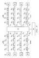
- FIG. 2shows another prior art cluster router network 18 that aggregates sixteen data lines 20 that each can carry up to one hundred sixty gigabit per second of data that appears to have the potential capacity of 2.5 Terabits (16 lines carrying 160 Gbps each).
- Each of the data lines 20is routed through an edge router 22 to an interconnected edge network 24 (e.g., a ring, mesh, ADM backbone or, other known interconnection method) via carrying lines 26 .
- edge network 24e.g., a ring, mesh, ADM backbone or, other known interconnection method
- the edge routersare each 320 Gbps routers
- 160 Gbpsis used to take incoming data from incoming data line 20 and only 160 Gbps of access remains to send data to each of the other fifteen routers 22 in the cluster 18 (i.e., approximately 10 Gbps can be allotted to each of the other fifteen routers, resulting in greater than 90% blockage of data between routers).
- the capacity of the routersis already underutilized as the overall router capacity of the network cluster 18 is 5 terabits per second (Tbps), while the data capacity actually being serviced is 2.5 Tbps. Even with the router capacity underutilized, the network 18 has over 90% blockage between interconnected routers through the edge network 24 . To increase the capacity between routers in a non-blocking manner, the individual routers would need to be increased in capacity tremendously, which increases cost and further exacerbates the underutilization problems already existing in the network.
- the present inventionprovides a non-blocking optical routing system and method that substantially eliminates or reduces disadvantages and problems associated with previously developed optical-routing systems and methods.
- the present inventionprovides a system and method for providing non-blocking routing of optical data through a telecommunications network that allows full utilization of available capacity.
- the networkincludes a number of data links that carry optical data packets to and from an optical router.
- the optical routerincludes a number of ingress edge units coupled to an optical switch core coupled further to a number of egress edge units.
- the ingress edge unitsreceive the optical data packets from the data links and aggregate the optical data packets into “super packets” where each super packet is to be routed to a particular destination egress edge unit or port.
- the super packetsare sent from the ingress edge units to an optical switch fabric within the optical switch core that routes each super packet through the optical switch fabric to the super packet's particular destination egress edge unit in a non-blocking manner (i.e., without contention or data loss through the optical switch fabric).
- This routingis managed by a core controller that monitors the flow of incoming optical data packets into each ingress edge unit, controls the generation of super packets from the incoming optical data packets and transmission of super packets to the optical switch fabric, and schedules each super packet to exit the optical switch fabric so as to avoid contention among the plurality of super packets in the transmission between the optical switch fabric and the egress edge units.
- the core controllermonitors traffic characteristics such as incoming traffic demand at each ingress edge unit, traffic routing demand to each egress edge unit, quality of service requirements, and other data to compute a scheduling pattern for sending super packets to the optical switch fabric.
- the core controllerthen schedules super packets based on the scheduling pattern (which is updated as the data traffic characteristics change).
- the egress edge unitsreceive the super packets, de-aggregate (i.e., disassemble) the super packets into the optical data packets, and transmit the optical data packets to the data lines.
- de-aggregated optical data packetscontain the same payload as the original incoming data packets, but can potentially have different overhead data due to routing through the router.
- the present inventionalso provides the capability of transporting super packets from the ingress edge to the optical switch core and from the optical switch core to the egress edge of the router on multiple wavelengths with each wavelength carrying a fraction of the super packet simultaneously.
- the present inventionprovides an important technical advantage with respect to previous optical routing systems and methods by optimizing bandwidth management to provide maximum data throughput with no (or greatly reduced) data loss due to congestion or contention within or collisions between optical data packets in an optical switching core of the optical routing system.
- the present inventionprovides another important technical advantage by providing non-blocking data processing (switching and routing) without increasing the individual router/switch capacity beyond the capacity being serviced.
- the present inventionprovides a technical advantage by establishing a switching pattern to route data packets based on traffic requirements at any single point in the network to avoid congestion or blocking of data packets while maximizing utilization.
- the present inventionprovides yet another technical advantage by providing an optical crossbar switch fabric that includes a unique switch path from each ingress (input) port to each egress (output) port to ensure that no blocking or congestion will occur in the switch fabric itself.
- the present inventionprovides yet another technical advantage by aggregating the received incoming optical data packets into super packets for transport through the optical switch/router in order to optimize throughput through the switch/router.
- the aggregationcan be an aggregation of data packets (based, for example, on destination and quality of service requirements) into all optical super packets, into all electrical super packets or perhaps even a combination of both.
- the present inventionis an optical telecommunications network that includes all of the technical advantages inherent in optical systems (e.g., increased speed, the ability to send multiple packets simultaneously over a single fiber, etc.).
- the present inventionprovides another technical advantage by performing packet classification one time at the ingress edge and carrying that classification information in a classification index to the egress edge of the router.
- This packet classificationenhances performance of a router by (i) reducing packet processing complexity at the egress edge and (ii) eliminating the classification computational requirements at the egress edge.
- the present inventionprovides yet another technical advantage by transporting super packets between ingress and egress edge units on multiple wavelengths so that each wavelength carries a fraction of the super packet simultaneously. This advantage enhances throughput and reduces the complexity of the switch fabric of the present invention.
- FIG. 1shows a prior art telecommunications router network
- FIG. 2shows another prior art telecommunications router configuration
- FIG. 3is a diagram representing one embodiment of an optical telecommunications network according to the present invention.
- FIG. 4shows one embodiment of the optical router of the present invention
- FIG. 5is a more detailed view of an optical switch fabric and an optical core controller for the optical router of FIG. 4;
- FIG. 6shows an optical cross-bar switch embodiment of the optical switch fabric of FIG. 5;
- FIG. 7shows a diagram representing one embodiment of optical packet aggregation according to the present invention.
- FIG. 8shows an example of optical switching and patterning according to the present invention for an even data distribution that results in non-blocking, full utilization packet processing
- FIG. 9shows an example of optical switching and patterning according to the present invention for an uneven data distribution that results in non-blocking, full utilization packet processing
- FIGS. 10 and 11are diagrams illustrating a scheduling algorithm for a four edge unit system over a time interval that allows the building of ten super packets that produces scheduling patterns that provide non-blocking, full utilization packet switching;
- FIG. 12 ais an embodiment of an ingress edge unit according to the present invention.
- FIG. 12 bis an embodiment of an egress edge unit according to the present invention.
- FIG. 13shows one embodiment of an ingress super packet processor of an ingress edge unit according to the present invention
- FIG. 14shows one embodiment of an ingress super packet factory of an ingress edge unit according to the present invention
- FIG. 15shows one embodiment of an egress super packet factory of an egress edge unit according to the present invention
- FIG. 16shows one embodiment of an egress super packet processor of an egress edge unit according to the present invention
- FIG. 17shows an embodiment of the data path interconnect architecture of an optical router according to the present invention.
- FIG. 18shows an embodiment of the control path interconnect architecture of an optical router according to the present invention.
- FIG. 19shows one embodiment of a petabit version of the optical router of the present invention.
- FIG. 20shows an embodiment of an edge unit can be used in conjunction with the petabit optical router of FIG. 19;
- FIG. 21shows an embodiment of an optical switch fabric that can be used in conjunction with the petabit optical router of FIG. 19;
- FIG. 22shows a router that performs packet classification at the ingress edge unit and transports the packet classification data to the destination egress edge unit;
- FIG. 23shows an embodiment of a packet classification module of the router of FIG. 22
- FIG. 24shows an edge processor that re-performs packet classification at an egress edge unit
- FIG. 25shows an embodiment a classification index processing module of the router of FIG. 22
- FIG. 26shows an embodiment of a classification index according to the present invention
- FIG. 27shows an embodiment of the present invention the incorporates deflection routing
- FIGS. 28 a - 28 dshow examples of scheduling patterns that can be used in conjunction with deflection routing according to the present invention.
- FIGUREsPreferred embodiments of the present invention are illustrated in the FIGUREs, like numerals being used to refer to like and corresponding parts of the various drawings.
- the present inventionprovides an optical network and switch architecture that provides full, non-blocking interconnectivity without increasing the router/switch capacity beyond that required to service the data capacity coming into the router/switch from the communities being serviced.
- the present inventionprovides routing for fixed and variable length optical data packets of varying types (including Internet Protocol (IP), data, voice, TDM, ATM, voice over data, etc.) at speeds from sub-Terabit per second (Tbps) to significantly in excess of Petabit per second (Pbps).
- IPInternet Protocol
- TDMsub-Terabit per second
- PbpsPetabit per second
- the present inventionutilizes unique, non-blocking optical switching and, routing techniques and an optical architecture to obtain these benefits in speed and interconnected capacity in the network.
- FIG. 3shows an optical network 100 of the present invention including a number of data links 20 (or “data lines 20 ”) carrying optical data directly to a central optical router 50 .
- the data links 20can be optical links comprising fiber optic cable operable to carry optical data packets.
- the network 100 embodiment shown in FIG. 3includes sixteen data links 20 where each data link has a data capacity of 160 Gigabits per second (Gbps). Therefore, the network 100 of FIG. 3 has the same potential data capacity of the network of FIG. 2 (approximately 2.5 Tbps). However, unlike FIG. 2, the optical network 100 of FIG. 3 has replaced the sixteen individual routers 12 and the interconnected edge network 24 with a single optical router 50 according to the present invention.
- Each of the data links 20transmits optical data packets directly to optical router 50 for further processing.
- the optical router 50can route any amount of data received from any single data line 20 to any other data line 20 in a non-blocking manner, thus providing full interconnectivity between data lines 20 in the network 100 , thereby providing the potential for full capacity utilization.
- the optical router 50optimizes bandwidth management to maximize throughput from ingress ports to egress ports in the router 50 with little or no data loss due to data packet congestion or conflict.
- the present inventionhas eliminated the intermediate routers (and their associated underutilized capacity) and the interconnected edge network with a single optical router 50 .
- the present inventionis fully scalable to comprise different numbers of links, different link I/O formats, different data capacities per links, different sized optical routers and other different formats/capacities.
- the present inventionis fully; applicable to networks with total data transport capacities much less than 1 Tbps and significantly in excess of 1 Pbps and the general architectures described are not in any way limited to this specific 2.5 Tbps embodiment which is provided by way of example only.
- the “optical router 50 ” of the present inventionincludes the functions of switching and routing and is not limited to traditional “routing” functions, but includes the ability to do both switching and,routing.
- the optical router 50can replace constant bandwidth switches that are used in public switched transport network that exists today that carries constant bandwidth voice or video data (e.g., TDM data).
- the optical router 50 of the present inventioncan be deployed in both a single system (non-distributed) and in a distributed version of the system. While the FIGUREs generally illustrate a single, co-located system architecture, the present invention is equally applicable to a distributed network that uses an optical router of the present invention to replace traditional routers such as those described in FIGS. 1 and 2.
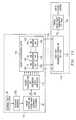
- FIG. 4shows an embodiment of the optical core node or optical router 50 of the present invention (specifically, the 2.5 Tbps embodiment of FIG. 3 ).
- the optical router 50includes an optical switch core 30 , that comprises an optical switch fabric 70 and a core controller 40 that manages the routing through the optical switch fabric 70 , a plurality of ingress edge units 60 linked to the optical switch fabric 70 via a plurality of ingress super packet links 32 and linked to the core controller 40 via a plurality of ingress control packet links 34 , and a plurality of egress edge units 160 linked to the optical switch fabric 70 via a plurality of egress super packet links 33 and linked to the core controller 40 via a plurality of egress control packet links 35 .
- the super packet links 32 and the control packet linkscan both comprise WDM fibers or ribbon. It should be further understood that the control packet links and super packet links can either comprise separate physical fibers/links or can combine a single physical fiber/link for both the control and data paths.
- the optical switch core 30is interconnected to a plurality of edge units 60 and 160 that interface between the data links 20 and the optical switch core 30 .
- Combined edge unitscan be built as a single. physical edge unit that includes both an ingress unit 60 and an egress unit 160 and that can perform both ingress (input) and egress (output) functions.
- Each ingress edge unit 60 and each egress edge unit 160can contain many ingress and egress ports (of different types), respectively, that can connect to a range of other optical network elements, such as smaller switches, routers, cross-connects, and/or transmission equipment that may require consolidation of large amounts of optical data.
- switch core 30can comprise a single switch core, or alternatively, can comprise a stack of switch cores or a multiple plane switch core.
- the ingress edge unit 60will receive the optical data packets and will convert the optical data packets to electrical data packets.
- Each ingress edge unit 60aggregates data packets (in electrical form) into egress addressable super packets for transmission over the ingress super packet links 32 , through the optical switch core 30 , and over egress super packet links 33 to an egress edge unit 160 .
- ingress edge units 60receive data from data links 20 , aggregates the data into super packets where each super packet contains data intended for the same egress edge unit 160 (as will be described more fully below), forwards the data in super packet form over ingress super packet links 32 to the optical switch fabric 70 in optical switch core 30 .
- a “super packet” as used hereinis an aggregated optical data packet that includes the data from converted data packets arriving at ingress edge units 60 that are intended for the same egress destination.
- Each ingress edge unit 60also connects to the core controller 40 via ingress control packet links 34 that carry control data packets to and from the core controller 40 to provide control data from each of the ingress edge units 60 that is used by the core controller 40 to perform the switch and routing management functions of the optical router 50 .
- Each ingress edge unit 60is shown in FIG. 4 receiving data from input/output lines 28 that interface between the ingress edge unit 60 and the data links 20 (through any number of smaller switches, routers, cross connects and/or transmission equipment).
- the input/output lines 28can be, for example, standard network interface port cards (e.g., OC-48 packet-over-Sonet port cards, OC-192 packet-over-Sonet port cards, Gigabit Ethernet port cards, etc.), DWDM interface port cards for aggregating multiple signals or other equally functional input/output units.
- the portitself could process multiple signal types aggregated into one or more input lines.
- the input/output lines 28need simply have the capacity to receive and send the amount of data provided over data links 20 .
- FIG. 4shows a specific embodiment of the present invention, however, it should be understood that the numerical values, ratios, etc. are exemplary only and that the present invention can be utilized with any number of ingress edge units and egress edge units and any capacity of super packet links, as long as the number of wavelengths times the capacity matches or exceeds the incoming capacity.
- there are sixteen ingress edge units 60(labeled I 1 , I 2 , I 3 , . . . I 16 ) and sixteen corresponding egress edge units 160 (labeled E 1 , E 2 , E 3 . . . E 16 ), that each has the capacity to send and receive 160 Gbps of optical data.
- I 1 , I 2 , I 3 , . . . I 16sixteen ingress edge units 60
- sixteen corresponding egress edge units 160(labeled E 1 , E 2 , E 3 . . . E 16 ), that each has the capacity to send and receive 160 Gbps of optical data.
- each ingress edge unit 60 and each egress edge unit 160has sixteen input/output lines (items 28 and 128 , respectively) where each of the sixteen input/output line group connects to one of the sixteen data links 20 and must be able to send/receive 160 Gbps of data from and to the data links 20 .
- Each ingress edge unit 60is connected to the optical switch core 30 through the single optical fiber ingress super packet link 32 that carries sixteen wavelengths ( ⁇ ) where each wavelength carries 10 Gbps each (to give a total carrying capacity across super packet link 26 of 160 Gbps).
- the total of sixteen 160 Gbps ingress super packet links 32(and the corresponding sixteen 160 Gbps egress super packet links 33 ) provide the 2.5 Tbps capacity of the optical router 50 .
- the optical router 50 of FIG. 4will allow all of the data, or any fraction thereof, to be transferred from the ingress to egress edges in a non-blocking manner (e.g., all of the data from ingress edge unit I 1 can go to egress edge unit E 16 , while at the same time all of the data from ingress I 2 goes to egress E 2 ).
- every data packet arriving at an ingress edge unit 60will be routed to an egress edge unit 160 without contention with any other data packet so long as the capacity of each of the individual ingress super packet links 32 and egress super packet links 33 are not exceeded.
- the egress super packet link 33 capacity to the egress edge unit 160cannot be exceeded (e.g., in this embodiment 160 Gbps).
- the core controller 40manages this control feature to ensure that this egress super packet link 33 capacity is not exceeded. In this manner, any portion of the input data at any ingress unit 60 can be routed simultaneous to any egress edge unit 160 , as long as the above control feature is followed.
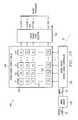
- FIG. 5shows a non-blocking embodiment of the optical switch core 30 of FIG. 4 in further detail.
- the optical switch core 30includes optical switch fabric 70 connected to edge units 60 via super packet links, and core controller 40 connected to edge units via control packet links.
- core controller 40can comprise a super packet scheduler 42 (which is the portion of the core controller 40 that communicates with the ingress edge units 60 through the ingress control packet links 34 and with the egress edge units 160 through the egress control packet links 35 ), and a switch controller 38 that is in communication between the packet scheduler 42 and the optical switch fabric 70 to coordinate the actual switching within the optical switch fabric 70 based on the information processed from the ingress edge units 60 .
- the super packet scheduler 42can be a single unit that performs the super packet scheduling and control, or can comprise multiple modules. In an alternative embodiment, the super packet scheduler can further comprise separate modules including a control packet processor module 44 , a congestion management module 46 and a scheduler module 48 . In the context of the present invention, the congestion management performed by the congestion management module 46 can include monitoring, reserving and allocating a path through the router 50 to avoid congestion.
- the switch controller 38may be an electrical control device. The switch controller 38 communicates with the optical switch fabric 70 through one or more switch links 36 through which the core controller 40 applies the pattern (i.e., schedule) to the optical switch fabric 70 .
- the optical router 50allows the non-blocking feature of the present invention by utilization of the optical switch fabric 70 non-blocking paths from each ingress edge unit 60 to each egress edge unit 160 to allow the flow of super packets without contention within the optical switch fabric 70 .
- the switch core controller 40communicates with each ingress edge unit 60 over ingress control packet links 34 in order to determine the incoming data destination requirements and schedule transmission of the aggregated super packets between ingress and egress edge interface functions to avoid collision or congestion.
- the core controller 40can perform at least three distinct control functions within the optical router 50 : (i) overall synchronization of data flow in the optical router 50 for both ingress edge units 60 and egress edge units 160 ; (ii) establishing patterns for delivery of super packets from the ingress edge units 60 to the optical switch fabric 70 and (iii) examination of the super packet data arriving at the egress edge units 160 to determine that the super packet data arrives at each of the egress edge units 160 at the scheduled time.
- the core controller 40monitors both the ingress edge units 60 via ingress control packet links 34 and the egress edge units 160 via egress control packet links 35 to monitor and control the overall router 50 synchronization.
- the core controller 40monitors ingress edge units 60 via ingress control packet links 34 to obtain management information (potentially including bandwidth, delay and quality of service information) to schedule the transmission of super packets from the ingress edge units 60 .
- the core controller 40monitors the egress edge units 160 via egress control packet links 35 to ensure the proper super packets arrive at each egress edge unit 160 at the proper time.
- the packet scheduler 42receives and processes control packet data from the ingress edge units 60 over the ingress control packet links 34 (e.g., using control packet processor 44 ). This information can be used by the congestion management module 46 to manage congestion along both the ingress super packet links 32 and along the egress super packet links 33 . Based on the congestion management, the super packet scheduler 42 (e.g., using scheduler module 48 ) will schedule the super packets to be switched through the optical switch fabric 70 to be sent out of the optical switch fabric 70 onto the appropriate egress super packet link 33 destined for a particular egress edge unit 160 .
- the super packet scheduler 42will develop a “pattern” that is delivered to the switch controller 38 for use by the switch controller 38 to open and close paths through the optical switch 70 .
- the patternis established so as to avoid congestion and/or overload of the egress super packet links 33 between the optical switch 70 and the egress edge units 160 .
- the patterncan be established using any number of data characteristic, including delay and other types of quality of service requirements, type of data and other data characteristics.
- the core controller 42can transmit and receive a variety of control data information from the egress edge units 160 .
- the core controller 40can monitor the egress edge units 160 to determine the amount of data arriving at each of the egress edge units 160 . In this manner, the core controller 40 can establish or modify the super packet transmission pattern so that no egress edge unit 160 receives an amount of data that will exceed the buffering capacity of the egress edge unit 160 .
- the present inventionhas primarily been described as a data transport product in which data packets are carried in various forms, the present invention can support circuit switched (TDM) data (as well as other forms of data), and could be used to replace large SONET based transmission or switching equipment.
- TDMcircuit switched
- rigid timing requirementscan be imposed on the router of the present invention.
- the patterned super packet transmission and switching scheme in the core optical fabricfacilitates these rigid timing requirements, while simplifying the multitude of real-time hardware tasks that must be scheduled at wire speed throughout the router.
- the routercan include redundant central control units (not shown) that can distributed the system time base to the ingress and egress edge units by way of the redundant control packet (fiber) links 34 connecting the switch core to each of these edge units (e.g., to each DWDM multiplexer and demultiplexer element).
- the router time-basecan be derived from a variety of redundant, external sources.
- the time-base or basic clock signalis 51.84 Mhz, the fundamental frequency of SONET transmission. At this frequency, SONET signals and tributaries can be recovered, as well as ordinary 64 Kbps DSO voice transmission that is based on 8 Khz.
- the optical switch corecan utilize the system time-base (51.84 Mhz) for all super packet and control packet transmissions to each edge unit. All of the super packet data between edge units and the optical switch core can be self-clocking and self-synchronizing.
- the edge unitwill recover data, clock, and synchronization from the super packet data within the DWDM subsystems and together with the control packet link from the optical switch core generates a local master clock (51.84 Mhz) for all edge unit operations, including transmission of super packet data to the optical switch core.
- the optical switch corefurther utilizes the control packet links for communication with each edge unit for JIT scheduling and verification of synchronization.
- the return path of this link from the edge unit back to the optical switch coreis also based on the system time-base as recovered by the edge unit. It is from this path back to the optical switch core that the router extracts the edge unit time-base and determines that all the edge units are remaining in synchronization with the system time-base.
- These control packet linksare duplicated between the optical switch core and all edge units, and therefore no single point of failure can cause a system time-base failure that would interrupt proper transmission and switching of super packet data throughout the system.
- FIG. 6shows an embodiment of the optical switch fabric 70 that includes an optical cross-bar switch 72 , one or more optional optical receivers 74 at the input of the switch 70 and one or more optional optical transmitters 76 at the output of the switch 70 .
- the switch controller 38is an integral part of the optical switch fabric 70 (rather than a part of the core controller 40 ). Again, switch links 36 connect from the switch controller 38 to the optical cross-bar switch 72 .
- optical receiver(s) 74 and optical transmitter(s) 76are optional, these devices can be used to filter and/or amplify the signals in the optical super packets upon receipt at the optical switch fabric 70 (i.e., at the optical receiver(s) 74 ) and just prior to exiting the optical switch fabric 70 (i.e., at the optical transmitter(s) 76 ) as necessary depending on the noise in the signals and the distance the signals must travel.
- Optical cross-bar switch 72includes an N ⁇ M switching matrix, where “N” can be the number of input data links and “M” can be the number of output data links serviced by the optical router 50 .
- the embodiment of FIG. 6shows a 16 ⁇ 16 matrix of switching elements 78 in the optical cross-bar switch 72 for the sixteen data link 20 , 2.5 Tbps optical router 50 configuration. While the switching elements 78 can be semiconductor (silicon) optical amplifiers (SOAs), it should be understood that other switching elements that are capable of transporting the data through the optical switch fabric 70 can be used. In the FIG. 6 embodiment, the switching elements 78 are shown as sixteen input, one output SOAs (16 ⁇ 1 SOAs) that are capable of routing any of sixteen inputs to its single output.
- the optical cross-bar switch 72comprises a set of sixteen switching elements 78 or SOAs 78 , each of which is connected to sixteen switch input lines 52 (labeled 52 - 1 , 52 - 2 . . . 52 - 16 ) and a single switch output line 54 (labeled 54 - 1 , 54 - 2 . . . 54 - 16 ).
- Each of the sixteen SOAs 78comprises sixteen path switches 56 where one path switch 56 is located at each intersection of an input line 52 and an output line 54 within each SOA 78 .
- Closing an individual path switch 56will allow super packets to flow through that path switch 56 (i.e., in from the input line 52 and out the output line 54 at that path switch 56 intersection), while opening a particular path switch 56 will prevent super packets from traveling down the output line 54 intersecting that particular path switch 56 .
- This “cross-bar” configuration of the optical switch 70allows for any a super packet to travel from any input 52 to any output 54 of the optical switch 70 along a unique path.
- sixteen 16 to 1 switching elements 78there are two hundred fifty six unique paths.
- the architecture of the optical switch core 30incorporating an optical cross-bar switch 72 , will process this increases number of wavelengths equally efficiently without changing the optical switch core base architecture.
- the embodiment of the optical switch fabric 70 shown in FIG. 6 comprising an optical cross-bar switch 72is only one example of a switch fabric 70 that can be used in conjunction with the present invention.
- Other non-blocking (and even blocking) switch architecturescan be used to accomplish the increased switching capabilities of the present invention (e.g., multi-stage switches, switches with optical buffering, etc.).
- the embodiment of the optical cross-bar switch 72 of FIG. 6 incorporating sixteen 16 ⁇ 1 SOAsis merely exemplary as other switching element configurations that can pass any input to any output of the optical switch 70 , in preferably a non-blocking manner, are equally applicable to the present invention.
- the optical switch 70could comprise two hundred fifty six individual switching elements (or SOAs) to form a similar cross-connected optical switch 70 with paths from any input pin to any output pin.
- the optical cross-bar switch 72provides a configuration that facilitates broadcasting and multicasting of data packets. Due to the cross-bar nature of the switch 70 , any data packet input to the optical cross-bar switch 72 at a particular input 52 can be sent out any single output 54 , all outputs 54 simultaneously, or to some selection of the total number of outputs 54 (e.g., a data packet arriving at from switch input line 52 - 1 can be replicated sixteen times and sent through each of switch output lines 54 - 1 through 54 - 16 simultaneously for a broadcast message).
- the optical cross-bar switch 72 provided in FIG. 6provides the additional advantage of being single-stage switch that is non-blocking without using buffering in the optical switch.
- the optical super packetsare received at the optical receiver(s) 74 on the ingress side, amplified and/or filtered as necessary, and transmitted through the optical cross-bar switch 72 to the optical transmitter(s) 76 on the egress side of the optical switch 70 .
- switch controller 38communicates with the optical cross-bar switch 72 through one of sixteen switch links 36 as shown.
- Each of the sixteen switch links 36connects to one of the SOAs 78 to open or close, as appropriate, the sixteen path switches 56 within the SOA 78 .
- switch controller 38would close path switch 56 at the intersection of 52 - 1 and 54 - 1 which would send the super packet from the optical receiver 74 to the optical cross-bar switch 72 along input line 52 - 1 to output line 54 - 1 and to optical transmitter 76 out of optical cross-bar switch 72 .
- switch controller 38would close path switch 56 at the intersection of 52 - 1 and 54 - 1 which would send the super packet from the optical receiver 74 to the optical cross-bar switch 72 along input line 52 - 1 to output line 54 - 1 and to optical transmitter 76 out of optical cross-bar switch 72 .
- N ⁇ 1 SOA 78only one switch 56 will be closed at any one time, and subsequently only one path is available through any one SOA 78 at any given time.
- the super packetsWhen the super packets are received from the ingress edge units 60 , these super packets can be routed through the optical switch fabric 70 in a manner that avoids contention.
- the FIG. 6 embodiment of the optical switch fabric 70accomplishes this contention-free routing using the optical cross-bar switch 72 .
- the optical cross-bar switch 72provides a unique path through the optical switch fabric 70 between every ingress edge unit 60 and each egress interface edge unit 160 .
- the flow path for a super packetruns from one ingress edge,unit 60 through the ingress super packet link 32 associated with that ingress edge unit 60 to the optical cross-bar switch 72 , through the unique path within the optical cross-bar switch 70 to one egress edge unit 160 over its associated egress super packet link 33 .
- data packets from ingress edge unit I 1 that are intended for egress edge unit E 2travel a distinct route through the optical cross-bar switch 72 (versus, for example, data packets from ingress I 16 that are also intended for egress E 2 ), so that contention physically cannot occur in the optical cross bar switch 72 between different ingress edge units 60 sending data to the same egress edge unit 160 .
- the switch controller 38can operate on two different time scales: one for the data path control and one for the control path control.
- the switch controller 38will apply a dynamic set of commands to the optical cross-bar switch 72 to operate the switching elements 78 within the optical switch 70 at wire speeds (i.e., switching the incoming super packets from input 52 to output 54 at the rate at which the super packets are arriving at the optical cross-bar switch 72 ) in order to open and close the unique paths that need to be traveled the super packets to get the super packets from an ingress edge unit 60 to an egress edge unit 160 .
- the switch controller 38will apply a continually changing “pattern” to the optical cross-bar switch 72 to schedule the super packets transmission from the ingress edge units 60 over the ingress super packet links 32 through the optical switch fabric 70 and over the egress super packet links 33 to the egress edge units 160 in a manner that avoids contention.
- These scheduling patternsare determined by the super packet scheduler 42 over time and provided to the switch controller 38 .
- the pattern applied by the switch controller 38 to the optical cross-bar switch 72can change over time as determined by the super packet scheduler 42 in response to control data received from the ingress edge units 60 .
- the super packetsmay be one microsecond in duration (including a guard band gap between each super packet) so that the optical switch fabric 70 must be able to switch every input 52 to every output 54 in the optical cross-bar switch 72 between the one microsecond boundaries. During the guard band gap, the optical switch fabric 70 must switch all of the switching elements 78 to change the entire optical switch fabric 70 configuration.
- the super packet scheduler 42may be determining and applying updated super packet scheduling patterns (based on different data flow detected at the ingress edge units) for time periods on the order of, for example, 1-10 milliseconds.
- the super packet scheduler 42may be providing to the ingress edge units 60 a new “pattern” every 1-10 milliseconds, while providing the switch controller 38 a switching signal based on the active patter that causes the switch controller 38 to update the optical cross-bar 72 configuration every 1 microsecond.
- FIG. 7shows an illustration of an optical burst packet aggregation scheme 80 that can be used in accordance with the present invention to aggregate optical data intended for the same egress edge unit destination into an aggregated “super packet.”
- the optical burst packet aggregation scheme 80 shown in FIG. 7is shown for four edge unit embodiment of the optical router 50 for ease of illustration, and it should be understood that the optical burst packet aggregation scheme 80 shown is equally applicable to optical routers 50 having any number of edge units.
- FIG. 7shows schematically a set of optical bursts 82 from each of the four ingress edge units 60 (repeating over time) contained on a single ingress super packet link 32 that will be sent to one of the switch input lines 52 at the optical switch fabric 70 .
- FIG. 7shows schematically a set of optical bursts 82 from each of the four ingress edge units 60 (repeating over time) contained on a single ingress super packet link 32 that will be sent to one of the switch input lines 52 at the optical switch fabric 70
- FIG. 7shows the ingress super packet link 32 transporting data over sixteen lambdas (i.e., individual wavelengths or different colors of light upon which optical data can travel) at a point where the optical burst 82 are leaving an ingress edge unit 60 destined for the optical switch core 30 .
- FIG. 7shows a single ingress edge unit 60 placing four equally sized data packets on the ingress super packet link 32 , where each data packet is intended for one of the four egress edge units 160 in successive time intervals in a repeating pattern. As shown in FIG.
- the first ingress edge unit 60places data packet 82 1 on the ingress super packet link 32 , then places data packet 82 2 on the ingress super packet link 32 , then places data packet 82 3 on the ingress super packet link 32 , and finally places data packet 82 4 on the ingress super packet link 32 (and then the cycle repeats).
- the notation 82 1 for a data packetsimply indicates that the packet 82 came from ingress edge unit number 1 (and not that each 82 1 have identical data, which they do not).
- FIG. 7shows the optical burst aggregation 80 for the case where there is an equally distributed amount of data going from a single ingress edge unit 60 is sent to each of the four egress edge units 160 (i.e., a static flow of data).
- the datais time multiplexed so that every fourth burst goes to a particular egress edge unit. It should be understood that in operation the data flow will change over time and that FIG. 7 is only one illustration of the potential data flows.
- FIG. 7also shows an enlarged view of the individual data packet 82 1 that is intended for the first egress edge unit 160 .
- Data packet 82 1can be one microsecond in duration and can comprise sixteen lambdas, wherein within each lambda contains a number of variable length packets 83 , or fractions thereof. The number of lambdas can be increased to any number so long as the individual packets are not lost due to interference or noise between the lambdas while traversing from ingress edge unit 60 to egress edge unit 160 .
- the variable length packets 83 shown in FIG. 7are illustrated as six variable length packets contained in each lambda, though the packets can wrap around to overlap more than one lambda. Thus, as shown in FIG. 7, the data packet.
- 82 1is a super packet containing 96 individual variable length packets 83 , all destined for the same egress edge unit 160 (i.e., the “first” egress edge unit). It should be understood that the super packet could comprise a single data packet or any other number of data packets that filled up all or a portion of the space available in the sixteen lamdbas (i.e., there are no limitations on the number of individual packets contained within a super packet).
- FIG. 7illustrates that the present invention can aggregate data at each ingress edge unit 60 into super packets prior to forwarding the data to the egress edge unit 160 for which the data is intended.
- the core controller 40will uniquely close one path in the switch to the first egress edge unit 160 (at a time that will prevent blocking or congestion with other packets intended for the first edge unit 160 coming from any of the other three ingress edge units 60 ) to allow the super packet 82 1 to be transmitted to the first egress edge unit 160 .
- FIGS. 8-11illustrate several examples of “slot routing” of super packets according to the present invention.
- FIGS. 8-9show super packet aggregation and switching for the four ingress/four egress edge unit configuration of FIG. 7 with equal egress distribution (i.e., one fourth of the received optical data at each ingress edge unit 60 is intended for each of the four egress edge units 160 ).
- FIG. 8specifically illustrates the situation where the initial bandwidth allocation is an even distribution (i.e., the super packets arriving on each ingress super packet link 32 from each ingress edge unit 60 arrive in an evenly distributed pattern).
- the super packets 82 to the left of the optical switch fabric 70illustrate a snapshot of time that shows sixteen super packets having been placed on the ingress super packet links 32 at four different times (t 0 , t 1 , t 2 and t 3 ).
- the super packets 82 to the right of the optical switch fabric 70illustrate the same sixteen super packets a time period “x” later after the sixteen super packets routed through the optical switch fabric and have been placed on the egress super packet links 33 .
- the first ingress edge unit 60places super packet 82 1 on ingress super packet link 32 1 at time t 0 , then places super packet 82 2 on ingress super packet link 32 1 at time t 1 , then places super packet 82 3 on ingress super packet link 32 1 at time t 2 , and finally places super packet 82 4 on ingress super packet link 32 1 at time t 3 .
- the second ingress edge unit 160places the four super packets on ingress super packet link 32 2 in the same order, but with each super packet delayed by one time unit (e.g., the second ingress edge unit 60 places super packet 82 4 on ingress super packet link 32 2 at time t 0 , then places super packet 82 1 on ingress super packet link 32 2 at time t 1 , then places super packet 82 2 on ingress super packet link 32 2 at time t 2 , and finally places super packet 82 3 on ingress super packet link 32 2 at time t 3 .).
- the third and fourth ingress edge unitsplace the super packets on ingress super packet links 32 3 and 32 4 in a similar pattern (each one more time unit delayed).
- the optical switch 70is always receiving four super packets, where each super packet is intended for a different egress edge unit 160 .
- super packet 82 1arrives on ingress super packet link 32 1
- super packet 82 4arrives on ingress super packet link 32 2
- super packet 82 3arrives on ingress super packet link 32 3
- super packet 82 4arrives on ingress super packet link 32 4 .
- the optical switch fabric 70in concert with optical core controller 40 , closes the switch connecting ingress super packet link 32 1 to egress super packet link 33 1 to place super packet 82 1 onto egress super packet link 33 1 destined for the first egress edge unit 160 .
- the optical switch fabric 70switches super packet 82 4 to egress super packet link 33 2 destined for the second egress edge unit 160 , super packet 82 3 to egress super packet link 33 3 destined for the third egress edge unit 160 and super packet 82 4 to egress super packet link 33 4 destined for the fourth egress edge unit 160 .
- the switching within optical switch fabric 70can occur as described earlier.
- the switching in the optical switch fabric 70can occur without induced delay and without contention.
- the numerals shown in each of the super packets 82indicate the egress edge units 160 to which the super packet is destined (e.g., the subscript numeral “1” in super packet 82 1 on egress super packet link 33 1 at time to+x indicates that the super packet is destined for the first egress edge unit 160 ).
- each of the super packets 82is processed similarly so that at a time “x” later, each super packet 82 has been routed to the appropriate egress super packet link 33 connected to the egress edge unit 160 for which the super packet is destined. Thus, each of the super packets 82 1 gets routed to the first egress edge unit 160 via egress super packet link 33 1 .
- FIG. 8illustrates a switching and routing system and method where there is no loss of super packet link capacity or loss of data, even under a one hundred percent utilization scenario.
- a one hundred percent utilization scenariois one in which there are no “gaps” in data out of the optical switch fabric 70 to the egress edge units 160 , other than the switching time gap 58 which is necessary under current switching technology (e.g., SOA technology and/or other switching/control technology) to prevent distortion of the super packets 82 during switching.
- current switching technologye.g., SOA technology and/or other switching/control technology
- the switching gap requiredcan be on the order of approximately 5-10 nanoseconds.
- the architecture of the present inventioncan use and take advantage of faster switching technologies that provide smaller switching gaps 58 .
- the optical switch fabric 70is closing four switch paths simultaneously (to place each of the incoming super packets on a different egress super packet link 33 ) without congestion because of the non-blocking nature of the optical switch fabric 70 .
- FIG. 9shows the system of FIG. 8 operating under an uneven distribution data scenario while still obtaining one hundred percent utilization, provided that at each time interval each super packet that arrives at the optical switch 70 is destined for a different egress edge unit 160 .
- the uneven distribution of FIG. 9results in no super packet 82 2 destined for the second egress edge unit over time periods t 0 , t 1 , t 2 and t 3 originating from the first ingress edge unit 60 (shown on super packet link 32 1 ).
- each super packet arriving at the optical switch fabric 70is intended for a different egress destination.
- the switching within the optical switch fabric 70can occur as described in FIG. 8 to allow simultaneous switching of each of the arriving super packets onto a different egress super packet link 33 .
- the present inventionachieves one hundred percent utilization with no loss of data or contention between data packets.
- the one hundred percent utilizationis accomplished by aggregating super packets at the ingress edge units 60 and sending them to the optical switch fabric 70 so that, at any time interval, one and only one super packet arrives for each of the egress edge units 160 .
- Thisis accomplished by analyzing the incoming data arriving at each of the ingress edge units and developing patterns of super packet delivery (based on destination egress edge unit) from each ingress edge unit 60 to the optical switch fabric 70 .
- This process of analysis and pattern developmentis accomplished by the core controller 40 based on input from all of the ingress edge units 60 .
- the core controller 40instructs each ingress edge unit 60 how to arrange the incoming data into super packets, and at what order to send the super packets to the optical switch fabric 70 based on the egress destination for each super packet.
- This “pattern” of sending super packets intended for particular destinations at particular time intervals from each ingress edge unit 60will result in all the super packets arriving at the optical switch fabric 70 at a particular time being intended for different egress edge units 160 .
- Thisallows the non-blocking switch fabric 70 to switch each of the arriving super packets to the appropriate output egress edge unit 160 at approximately the same time and provides full utilization of the data transport capacity. Delivery of super packets to the optical switch fabric 70 according to this “pattern” prevents collisions by ensuring that two super packets intended for the same egress edge unit 160 do not arrive at the optical switch fabric 70 at the same time. Further, as shown in FIG.
- the core controller 40can impose a pattern that fully utilizes capacity (i.e., no gaps between super packets on the egress super packet links 33 ).
- the present inventioncan avoid collisions and loss of data, while maximizing utilization through pattern development using the core controller 40 in conjunction with a non-blocking optical switch fabric 70 and a super packet building capacity at the ingress edge units 60 .
- Thisprovides an advantage over previously developed optical switching and routing systems which simply minimize the number of collisions of data.
- the present inventioncan avoid collisions altogether based on scheduling incoming data through a non-blocking optical switch 70 based on the data destinations (not just limiting collisions to statistical occurrences).
- the pattern developed by the core controller 40is dependent upon the destination of incoming packets at the ingress edge units 60 (and can be dependent on many other packet flow characteristics such as quality of service requirements and other characteristics).
- the pattern developedmust avoid the arrival of two super packets intended for the same egress edge unit 160 at the same time. Any pattern that avoids this issue is acceptable for processing super packets from ingress to egress edge units.
- the patterncan be further optimized by examining other packet flow characteristics.
- the patterncan be updated in a regular time interval or any other metric (e.g., under-utilization of an egress super packet link 33 of a particular magnitude, etc . . . ).
- the period of time a pattern can remain in placecan depend upon the rate of change in incoming data destination distribution across each of the ingress edge units 60 (i.e., the more consistent the data destination at each ingress edge unit 60 , the longer a particular pattern can remain in effect). Furthermore, the building of super packets at the ingress edge units 60 based on destination provides the ability to maximize utilization of the data processing capacity, even when the destination distribution of incoming data at each ingress edge unit 60 is uneven. In other words, the switch core controller 40 monitors all the ingress edge units 60 to allow the data from any ingress unit 60 to be switched to any egress edge unit 160 without contention in the optical switch core fabric 70 using a “just in time” scheduling algorithm practiced by the core controller 40 .
- FIGS. 10 and 11shows graphically a more complex incoming data distribution at each of four ingress edge unit 60 and a scheduling algorithm that will result in no contention and one hundred percent utilization.
- Each ingress edge unit 60receives enough incoming data to create and/or fill ten super packets, with an uneven distribution across the destinations of the super packets.
- the data distribution diagram 62 for ingress edge unit # 1shows that the incoming data at ingress edge unit # 1 will create per time unit (t) one super packet 82 1 intended for egress edge unit number 1 , four super packets 82 2 intended for egress edge unit number 2 , three super packets 82 3 intended for egress edge unit number 3 , and two super packets 82 4 intended for egress edge unit number 4 .
- the data distribution diagram 64shows that the data distribution for ingress edge unit # 2 is two super packets 82 1 intended for egress edge unit number 1 , one super packet 82 2 intended for egress edge unit number 2 , three super packets 82 3 intended for egress edge unit number 3 , and four super packets 82 4 intended for egress edge unit number 4 .
- Data distribution diagram 66 for ingress edge unit # 3shows three super packets 82 1 intended for egress edge unit number 1 , two super packets 82 2 intended for egress edge unit number 2 , two super packets 82 3 intended for egress edge unit number 3 , and three super packets 82 4 intended for egress edge unit number 4 .
- data distribution diagram 68 for ingress edge unit # 4shows four super packets 82 1 intended for egress edge unit number. 1 , three super packets 82 2 intended for egress edge unit number 2 , two super packets 82 3 intended for egress edge unit number 3 , and one super packet 82 4 intended for egress edge unit number 4 .
- Each ingress edge unit 60can be built to have an identical amount of bandwidth per unit of time used to transport data to the optical switch core 30 . In such a case, each ingress edge unit 60 can only produce a fixed number of super packets per unit of time because of the fixed available bandwidth. In the case of FIG. 10, each ingress edge unit 60 produces ten super packets for the defined time interval. It should be understood that while each edge unit could not produce a greater number of super packets than the allocated bandwidth, each could produce fewer than the maximum number (though this would not represent a fully congested situation) and each could produce an unequal number of super packets.
- FIG. 11shows data scheduling patterns for each of the four ingress edge units 60 based on the uneven distribution described in FIG. 10 that result from a scheduling algorithm that allows for non-blocking scheduling with full utilization in a fully congested data flow scenario.
- the resulting scheduling patterns 84 , 86 , 88 and 90will provide super packet data to the optical switch fabric 70 so that no two super packets intended for the same egress edge unit 160 arrive at the same time and there are no data gaps (i.e., full capacity utilization) between super packets from the optical switch 70 to the egress edge units 160 .
- the scheduling patterns of FIG. 11can be repeated to allow non-blocking, fully utilized super packet data switching and delivery.
- the scheduling pattern 84 for ingress edge unit # 1shows the outputting of super packets from ingress edge unit # 1 onto ingress super packet link 32 1 in the following order: one super packet 82 1 , one super packet 82 2 , one super packet 82 3 , two super packets 82 4 , one super packet 82 2 , one super packet 82 3 , one super packet 82 2 , one super packet 82 3 and finally one super packet 82 2 (where the subscript indicates the destination edge unit).
- the scheduling pattern 86 for ingress edge unit # 2is as follows: one super packet 82 4 , one super packet 82 1 , one super packet 82 2 , one super packets 82 3 , one super packet 82 1 , two super packets 82 4 , one super packet 82 3 , one super packet 82 4 and finally one super packet 82 3 .
- the scheduling pattern 88 for ingress edge unit # 3 and the scheduling pattern 90 for ingress edge unit # 4are as indicated in FIG. 11 . It can easily be seen that for any selected time, these four scheduling pattern result in four super packets that are destined for a different egress edge unit 160 .
- FIG. 11illustrates another technical advantage of the present invention in that the present invention can run in a congested mode (i.e., full utilization) at all times with no packet collision or loss of data. This full utilization maximizes the throughput of data over the available capacity.
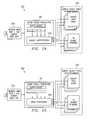
- FIG. 12 ashows in more detail a block diagram of one embodiment of an ingress edge unit 60 of the present invention. While the specific embodiment of the ingress edge unit 60 of FIG. 12 a is a 160 Gigabit ingress edge unit 60 , it should be understood that the ingress edge unit 60 is scalable to accommodate any data rate.
- the input to the ingress edge unit 60comes from a series of ingress network ports 28 , where each ingress network port 28 connects to one of multiple ingress edge interface port cards 92 , each ingress port card 92 connects to one of multiple ingress super packet processors 110 , and each ingress super packet processor 110 connects to a single ingress super packet factory 120 .
- the ingress network ports 28comprise sixteen 10 Gbps ports, where each ingress network port 28 connects to one of sixteen ingress edge interface port cards 92 .
- the classified data from each of the ingress port cards 92is sent to the associated ingress super packet processors 110 for queuing based on the data type contained in the incoming data packets (to create “partial” super packets that contain data that is destined for a particular egress edge unit 160 .), and from the super packet processors 110 is then sent to the ingress super packet factory 120 where the super packets are queued and constructed, based on the destination port of the incoming data, for delivery to the appropriate egress edge unit 160 .
- the packet classification, partial super packet construction and super packet aggregation functionscan be performed by different physical units (e.g., the packet classification can be accomplished on the port card 92 ).
- the super packetsare delivered from the ingress super packet factory 120 over an edge unit DWDM optical fiber 94 across multiple lambda (e.g., sixteen lambda).
- lambdae.g. sixteen lambda
- the overall capacity of the ingress edge unit 60can be increased proportionally (e.g., if the number of wavelengths that can be accommodated over the DWDM optical fiber increases from sixteen to thirty-two, the overall capacity of the edge unit can be increased to 320 Gbps by increasing the number of ingress port cards 92 and ingress super packet processors 110 to thirty-two each (and receiving incoming data from thirty-two network ports 28 at 10 Gbps each).
- FIG. 12 bshows in more detail a block diagram of one embodiment of an egress edge unit 160 of the present invention. While the specific embodiment of the egress edge unit 160 of FIG. 12 b is a 160 Gigabit egress edge unit 160 , it should be understood that the egress edge unit 160 is scalable to accommodate any data rate.
- the input to the egress edge unit 160is a super packet link 33 from the optical switch 70 that delivers super packets destined for that particular egress edge unit 160 to the egress super packet factory 140 .
- the super packetsare de-aggregated (i.e., de-constructed or disassembled) into egress partial super packets (i.e., containing data intended for a particular egress destination port 128 ) and delivered from the egress super packet factory 140 to the egress super packet processor 150 .
- the egress super packet processor 150processes the partial super packets to an egress edge unit 166 , further to egress network ports 128 .
- FIG. 13shows one embodiment of an ingress super packet processor 110 that is receiving data from the network port 28 , processing the data, and forwarding the incoming data to an ingress super packet factory 120 .
- Incoming datais received through ingress network port 28 to an ingress interface port 92 that provides an interface to allow incoming data to be processed through the ingress super packet processor 110 .
- the datacould represent OC192 packet-over-sonet data that is converted from an optical signal an electrical signal in order to allow for timing recovery at the ingress port interface 92 (or other data packet format, such as OC48, packet-over-wavelength, IP, etc . . . ).
- the datais then forwarded to a packet detector 96 to determine the beginning and ending of the incoming packets.
- the packet detector 96can also phase align the incoming data and converts the incoming data from a serial format to a parallel format (e.g., 64 bit parallel).
- the packet classification processis used to classify the data contained in the optical (or converted to electrical) data packets. Based on the packet classification, the packet classification controller 112 can route the incoming packets into appropriate destination queues within the packet classification queue 114 that comprises a variety of queues.
- the packet classification queue 114is a memory device containing individual queues (or buffers) for storing various portions of the incoming data packets.
- packet classificationis performed by the packet classification controller 112 which can examine the header information for each incoming data packet to determine (i) to which egress edge unit 160 each incoming data packet is destined (ii) to which egress port 128 at the destination egress edge unit it is destined and (iii) other data routing characteristics (e.g., quality of service requirements and whether the incoming data packet contains TDM data (i.e., any non-packet data such as voice data, video data or other constant bandwidth data)-or packet data).
- TDM datai.e., any non-packet data such as voice data, video data or other constant bandwidth data
- the packet classification controller 112will route the TDM data to TDM queues 104 while routing packet data to PKT queues 106 within the packet classification queue 114 .
- the ingress port 92will perform the packet classification as is more fully described at FIGS. 22-26.
- TDM queues 104there is one set of TDM queues 104 (sixteen in the specific example) and one set of PKT queues 106 (again, sixteen for the FIG. 13 example). It should be understood that there can be additional sets of PKT queues 106 (for example, a different set of PKT queues for each different quality of service requirement for the packet data) and TDM queues 104 . The example of one set of each type of queue is for illustration purposes only. The number of TDM queues 104 and PKT queues 106 within each set of TDM and PKT queues is determined by the number of egress edge interface destinations available. In the example of FIG. 13, there are sixteen potential egress edge units 160 that are potential destination points for any incoming data packet.
- each TDM queue 104 and each PKT queue 106is assigned to one of the sixteen egress edge units 160 .
- the TDM queue 104 assigned to the first egress edge unit 16 . 0collects the TDM data from incoming packets intended for the first egress edge unit 160
- the PKT queue 106 assigned to the first egress edge unit 160collects the PKT data from incoming packets intended for the first egress edge unit.
- the remaining TDM queues 104 and PKT queues 106collect their respective data type from incoming data that is intended for the egress edge unit to which that particular queue is assigned.
- all of the TDM data intended for any particular egress edge unit 160gets collected in one particular TDM queue 104 and all of the packet data intended for any particular egress edge unit 160 gets collected in a single PKT queue 106 (and no packet data intended for any other egress edge unit 160 gets collected in that particular PKT queue 106 ).
- each packet classification queue 114begins the process of building super packets by building a “partial” super packet containing all of the data arriving at one specific network port 28 that is destined for a particular egress edge unit 160 . Furthermore, each packet classification queue can hold partial super packets addressed to each egress edge unit 160 in the optical router 50 . The partial super packets will remain in the packet classification queue 114 for an appropriate amount of time based on management of the packet classification queue 114 and the super packet ingress queue 124 . This queue management is a function of the incoming data bandwidth requirements and the depth and occupancy of the packet classification and super packet ingress queues.
- the partial super packetswill be extracted from the packet classification queue 114 in a manner that best avoids overflow of the packet classification queue 114 and the super packet ingress queue 124 .
- the partial super packetscan be output from the packet classification queue 114 when the partial super packets reach a predetermined size (or alternatively at predetermined time interval or some other metric), and the precise delay needed to control of delivery can be accomplished at the super packet ingress queue 124 .
- the patterncan be updated and applied to allocate that particular queue more bandwidth over the router 50 .
- Partial super packetsare forwarded to the ingress super packet factory 120 .
- each of the sixteen partial super packetscan be sent out on a different output line 192 to an edge unit destination controller 116 , then to a partial super packet transmitter 118 , and finally to ingress super packet factory 120 .
- the edge unit destination controller 116controls when and how much data gets removed from the packet classification queue 114 based on the current pattern.
- the edge unit destination controller 116provides control information (in the form of bandwidth management data) to the partial super packet ingress controller 122 and the ingress super packet transmit controller 126 .
- the super packet transmit controller 126receives this data and uses the data to create request bandwidth from the core controller 40 (which, in turn, uses this information from each ingress edge unit 60 to create the pattern).
- FIG. 14shows an embodiment of an ingress super packet factory 120 that receives the multiplexed partial super packets from each of the ingress super packet processors 110 for that particular ingress edge unit 60 .
- each of sixteen ingress super packet processors 110sends its multiplexed partial super packets to the ingress super packet processor 120 through one of the sixteen ports 108 into a partial super packet ingress queue controller 122 .
- the partial super packet ingress queue controller 122receives the partial super packets and places each partial super packet in a destination/lambda queue 130 within the super packet ingress queue 124 based on (i) the destination egress edge unit 160 for that partial super packet and (ii) the lambda upon which the partial super packet will appear.
- partial super packetsare destined for one of sixteen egress edge units 160 (illustrated by the sixteen rows of identical destination partial super packets, where each row is labeled E 1 , E 2 , . . . E 16 ) and are to be placed upon one of sixteen lambdas (illustrated by the sixteen columns of different destination partial super packets, where each column is labeled L 1 , L 2 , . . . L 16 ).
- Each destination/lambda queue 130can contain partial super packets from any or all of the ingress super packet processors 110 within that particular ingress edge unit 60 .
- the ingress super packet factory 120builds the super packets for any particular egress edge unit 160 by combining all of the partial super packets in any row of destination/lambda queues 132 within the super packet ingress queue 124 .
- a super packet destined for egress edge unit # 1should be forwarded to the optical switch core 130 from this particular ingress edge unit 60 (according to the pattern determined by the core controller 40 based on input received from the super packet transmit controller 126 relating to both the ingress super packet factory 120 bandwidth management data (looking at the super packet ingress queue 124 bandwidth) and the ingress super packet processor 110 bandwidth management data (looking at the packet classification queue 114 bandwidth management data.
- the super packet transmit controller 126will collect all of the E 1 partial super packet data in row number one (shown collectively as item 132 ) into a single super packet that can contain data intended for egress edge unit # 1 over any of the sixteen lambdas.
- the super packet transmit controller 126serializes the data contained in the first row 132 and sends serialized data out over sixteen lambdas to the DWDM generator 128 , which sends all sixteen lambdas to the optical switch core 130 over a single ingress super packet link 32 as a single super packet.
- the super packet transmit controller 126collects all of the data contained in the destination/lambda queues 130 in row two (collectively, shown as item 134 ), builds the super packet destined for egress edge unit number two and forwards the super packet to the optical switch core 130 .
- Super packets for each egress edge unit 160are built similarly in each ingress edge unit super packet factory 120 . It should be noted that super packets can contain both TDM and PKT data within a single super packet.
- TDM datawill receive priority over PKT data when building super packets, however, it should be understood that any prioritization mechanism can be employed when building super packets.
- the core controller 40can “reserve” a portion of the available bandwidth for a particular type(s) of data (e.g., TDM data) such that the reserved portion is not subject to change as the data flow changes. The remaining portion of the bandwidth that is not reserved can then be patterned in a variable manner based on the incoming data flow.
- the ingress super packet factory 120allocates a number of independent super packet buffers (queues 130 ) based on the number of egress destinations.
- the ingress super packet factory 120collects partial super packets from each of the appropriate ingress super packet factory buffers 130 in order to construct a complete super packet for each egress edge unit 160 .
- each of the queues 130has subdivided the super packet into as many channels as there are wavelengths (lambdas) being utilized in the particular DWDM scheme of the optical router 50 for transmission to the optical switch core 130 .
- the ingress super packet factory 120monitors the short-term average data flow to each of its rows of queues (each in essence a “sub-factory”) from the ingress super packet processors 110 and maintains a collection of information regarding the incoming data packets for each ingress edge unit 60 within the edge unit destination controller 116 .
- This collection of datacan include bandwidth demand, latency, and queuing depth among others for collecting the data routing information used to classify the incoming data packets.
- the optical core controller 30collects this data from each ingress super packet factory 120 (and therefore for each ingress edge unit 60 ) and creates the just in time (JIT) scheduling pattern that is provided back to each ingress super packet factory 120 .
- each super packetis built and sent from each sub-factory of the ingress super packet factory 120 according to the JIT scheduling pattern to maintain a proper bandwidth allocation of super packets on a per edge unit basis.
- This schedulingoptimizes transmit bandwidth with a set amount of delay from each of the ingress super packet factory 120 destination/lambda queues 130 to eliminate congestion in the optical switch fabric 70 and minimize buffer overflow (packet loss) in both the ingress super packet processors 110 and ingress the super packet factories 120 .
- FIGS. 15 and 16discuss the egress data flow through the egress edge units 160 and for the most part reverses the operations described in FIGS. 13 and 14.
- FIG. 15shows an embodiment of an egress super packet factory 140 that receives the super packets the optical switch core 130 , de-constructs the super packets into partial super packets based on output destination and places them in queues and forwards partial super packets from these queues to the appropriate egress super packet processor 150 .
- Super packets(with data potentially spanning all of the wavelengths available on the DWDM fibers) are received at the DWDM demultiplexer 136 on a single, multi-wavelength egress super packet link 33 from the optical switch fabric 70 .
- the demultiplexer 136demultiplexes the super packets and generates a optical stream for each wavelength in the DWDM lambda count (in our example, sixteen optical streams).
- the optical streamsare then forwarded to the super packet egress queue controller 138 that places each wavelength in a port/lambda queue 102 (within super packet egress queue 146 ) based on the port to which the data is destined and the wavelength upon which the data had traveled (arrived).
- the super packet port selector 142forwards the data collected in each port/lambda buffer 102 to the appropriate port destination and egress QoS queue (e.g., all of the data in the first row of port/lambda buffers 102 that is intended for port number 1 is sent via line 144 to the egress super packet processor 150 associated with port number 1 ).
- FIG. 16shows one embodiment of an egress super packet processor 150 that is receiving data from an egress super packet factory 140 , processes the super packet data and forwards the processed data to an output network port 128 .
- An egress super packet processor 150is associated with each output port 128 associated with each egress edge unit 160 .
- the egress super packet processor 150is one of sixteen egress super packet processors 150 that process data to each of the sixteen output ports 128 connected to that particular egress edge unit 160 .
- the egress super packet processor 150receives the data intended for its associated egress network port 128 at the super packet port receiver 148 and forwards the data to the packet declassification queue controller 152 .
- the packet declassification queue controller 152receives the data intended for the particular port, de-classifies the data into its TDM and packet components, and forwards the TDM data to TDM queues 154 and forwards the packet data to PKT queues 156 within packet declassification queue 158 .
- the TDM datacan be transmitted from the TDM queues 154 on an expedited schedule for insertion into the output data stream for the network port 28 .
- the packet declassification queue 158is used in the egress super packet processor 150 in order to avoid overflow (and therefore loss of data) at the output network port 128 .
- the schedulingis far less complex at the egress super packet processor 150 (as compared to the scheduling at the ingress super packet processor 110 ) because the potential conflict is only between those data packets leaving that particular egress super packet processor 150 .
- the packet selector 162selects TDM and packet data from the packet declassification queue 158 according to priority of the data based on the type of data is present and when data can be accepted at the output network port 128 .
- the packet selector 162will forward the data to the packet transmitter 164 for transmission to an interface module 166 to be converted into the proper format (TDM, packet or both) for transmission over the network through the network port 128 .
- the egress super packet processor 150is synchronizing with the timing and format requirements of the output network port 128 .
- FIGS. 17 and 18illustrate the path used to route the actual data through the optical network system 100 and the path used to route the control data for the optical network system 100 .
- FIG. 17shows an embodiment of the intra-system data path fiber interconnect 170 for a 2.5 terabit optical router 50 including OC192 packet-over-sonet interfaces to legacy networks.
- FIG. 17is essentially a combination of FIG. 4 and FIG. 12 for this particular architecture (other architectures of the present invention have similar data paths).
- Datais received at the optical router 50 from any number of OC192 ports 28 connected to a plurality of ingress edge units 60 (shown in FIG. 17 as sixteen OC192 ports for each of sixteen ingress edge units 60 ).
- the dataflows into each ingress edge unit 60 through to an ingress super packet processor 110 associated with the OC192 port 28 .
- All of the ingress super packet processors 110 for each ingress edge unit 60deliver data to an ingress super packet factory 120 for that edge unit 60 .
- the super packet data from the ingress super packet factory 120flows along sixteen lines to a multiplexer 128 and out the ingress super packet link 32 to the optical switch core 30 (comprising a core controller 40 and an optical switch fabric 70 ).
- the super packet dataflows out of the optical switch core 30 along egress super packet links 33 to egress edge units 160 .
- each egress edge unit 160the super packet data flows through a demultiplexer 136 and into an egress super packet factory 140 that de-constructs the super packets. From there the data flows through a plurality of egress super packet processors 150 and out of the optical router through network ports 128 .
- FIG. 18shows the control path 180 used in the optical network 100 to control the flow of data through the data path 170 of FIG. 17 and to control the synchronization of the router 50 .
- the control path 180features two levels of hierarchy where the top level is used for centralized, system wide control functions and the lower level is used for distributed, localized control functions.
- the control path architecture 180 top-level control functionsare located in a central control unit 176 and in the edge units.
- the central control unitcomprises optical switch core 30 , an Ethernet switch 182 (e.g., in the gigabit range), and an IP control cluster 186 , while the edge units can each contain a unit controller 184 .
- Each unit controller 184can also act as a bridge to the lower level for any distributed functions within each edge unit.
- Each unit controller 184can be connected to a multiplexer 191 or a demultiplexer 193 , for an ingress edge unit 60 or an egress edge unit 160 respectively, for multiplexing/demultiplexing the control and/or synchronization signals.
- the IP control cluster 186can contain all of the optical router 50 system applications, their management functionality and the microprocessors to implement the applications and functionality.
- Each microprocessor 188 in the IP control cluster 186 , each unit controller 184 in the edge units and the core controller 40all connect to the Ethernet switch 182 via data control links. This facilitates high bandwidth, high availability message exchanges between these elements to manage initialization, configuration, operation, fault management, and system upgrades and expansions.
- the unit controllers 184 within each edge unitmanage the local subsystems for both ingress and egress functions.
- the unit controller 184manages the lower level of the control hierarchy, which is facilitated by an integral 100BaseT Ethernet switch for direct, point-to-point message exchange between all of these subordinate elements (e.g., the network interfaces 92 , the super packet processors 110 , the super packet factory 120 , and the DWDM multiplexer for each ingress edge unit 60 ).
- the unit controller 184can also be responsible for management of all edge unit 60 equipment issues related to, for example, initialization, configuration, operation, fault tolerance (e.g., detection, isolation, and recovery), and local feature enhancements (ICOFE) at the subsystem or unit level.
- Each of the local edge unit elementscan contain a processor that manages these same internal ICOFE functions, strictly within that element.
- the control hierarchy 180 for the present inventioncan be partitioned into two levels that are self managed and maintained and can be represented by: 1) the lowest level replaceable elements at each edge, including the edge units themselves, and 2) the overall system 100 consisting of the edge units and the central control unit 176 .
- the central control unit 176(by way of the IP control cluster 186 ) has ultimate authority over the system control from a feature and network capability point-of-view.
- This control hierarchy 180can be used to support continual, subsystem product improvement without resulting in a detrimental ripple effect into other areas of the system that are not directly effected.
- FIG. 19illustrates the scalability of the present invention by showing an embodiment of a petabit optical routing system 200 in which the optical switch core 230 can be isolated from the edge units by distances along the order of thousands of miles.
- a petabit optical routing system 200requires sixteen terabit capacity edge packet processors to process a terabit of data, thus FIG. 19 shows sixty-four 16 terabit ingress edge units 210 a and sixty-four 16 terabit egress edge units 212 connected via a multiplexed optical fiber 232 to the optical switch core 230 .
- the petabit optical switch core 230comprises an optical core controller 240 and an optical switch fabric 270 that work in concert to provide the non-blocking switching described in the present invention.
- the petabit optical switch core 230can comprise a single machine, distributed architecture, or the optical switch core 230 could be co-located with any number of the edge units. In fact, it should be understood that any of the embodiments of the present invention described herein can comprise either a distributed or co-located architecture.
- the distributed architecture of the router of the present inventionhas the same functionality as the co-located case with a different physical implementation.
- the super packet links 32 (data paths) and the control packet links 34 (synchronization and control paths)must accommodate much greater distance between the central control unit and the edge units 60 , 160 .
- the top level communications links between the gigabit ethernet switch 182 and the edge unit core controllers 40can be embedded into the control packet links 34 .
- an OC192 functioncan be incorporated within the DWDM multiplexers (ingress edge units 60 ) and DWDM demultiplexers (egress edge units 160 ) in order to provide this control capability. In this manner, the control and synchronization can be accomplished similarly to the co-located embodiment.
- These larger (e.g., petabit) ingress and egress unitscan utilize multiple fiber optic cables to provide the necessary bandwidth, as shown in FIG. 20 .
- multiple super packetscan be transmitted simultaneously (addressing the same egress edge unit) while adhering to the same pattern or just-in-time schedule as if there were only one fiber cable (i.e., the individual super packet factory and DWDM functions are synchronized across multiple fibers to follow the pattern for that ingress edge unit).
- the super packet scheduleris ingress edge unit specific, not super packet factory or DWDM fiber specific.
- FIG. 20shows in greater detail one embodiment of the ingress edge unit 210 and the multiplexed ingress optical fiber 232 .
- the edge unit 210can connect to legacy network interfaces 214 to bring data into the petabit optical routing system 200 for processing at the ingress edge unit 210 (as previously described).
- the ingress edge unit 210will aggregate incoming data into super packets and forward the data over four DWDM fibers 234 to be bundled onto the single ingress optical cable 232 (comprising the fibers 234 ) leading to the petabit switch core 230 .
- Each of the DWDM fibers 234can comprises any number of lambdas, though the specific DWDM fibers 234 of FIG. 20 are shown having 100 lambdas with each lambda carrying 40 Gbps to provide a capacity of four terabits per DWDM fiber 234 .
- FIG. 21shows an embodiment of the petabit optical switch fabric 270 of FIG. 20 comprising an optical cross bar switch utilizing 2048 DWDM SOA switching elements 278 .
- the petabit optical switch fabric 270can comprise eight groups 280 (or rows 280 ) of selectors 278 , where each row can accept 32 input lines and 256 columns of selectors 278 .
- the selectors 78are shown as 32 to 1 selectors operable to receive 32 data inputs and switch them to one of 256 data outputs (to be sent forward to one of the sixteen egress edge packet processors 212 for further processing).
- each group (or row) of selectors 278receives data from eight of the sixty-four ingress edge packet processors 210 .
- the general operation and architecture of the petabit routing system 200is as described earlier, it is simply scaled to a petabit capacity. Other architectures, both larger and smaller, can be accomplished using the general architecture and operation described herein.
- FIG. 22shows a router 50 that performs packet classification at the ingress edge unit 60 and transports the packet classification data to the destination egress edge unit 160 so that packet classification need not be repeated at the egress edge unit 160 .
- the network 300includes a set of ingress legacy ports 28 coupled to the router 50 that routes data from the ingress legacy ports 28 , through ingress edge unit 60 , out an ingress edge unit core output port 252 to the switch core 30 , into an egress edge unit core input port 254 , through the egress edge unit 160 to the egress legacy ports 128 .
- the ingress edge unit core output port 252is an output DWDM port 252 and the egress edge unit core input port 254 is an input DWDM port 254 .
- Each ingress edge unit 60can include a packet classification module 250 and an ingress super packet factory 120 and each egress edge unit 160 can include a classification index processing module 260 and an egress super packet factory 140 .
- the packet classification module 250is contained within the port card 92 and the packet classification index processing module 260 is contained within the egress super packet factory 140 .
- the packet classification module 250 functionality and the packet classification index processing module 260 functionalitycan be contained in any number of other units (e.g., super packet processors).
- the ingress edge unit 60can also include an egress port scheduler 270 (shown in FIG. 23 ).
- the functions at the ingress edgeinclude packet classification and packet index building (performed in the FIG.
- the functions at the egress edgeinclude super packet disassembly (performed by the egress super packet factory 140 ) and classification index review for packet routing (performed by the classification index processing module 260 ).
- the ingress legacy ports 28can carry any kind of telecommunications data, including packet over SONET or 10 Gigabit Ethernet data to ingress edge unit 60 .
- the packet classification module 250can first make a determination of whether or not the packet qualifies for wire speed classification.
- the wire speed classificationis go/no-go determination of whether the data packet can be sent at a particular speed and, if not, the data packet is dropped to a slow path.
- a number of parameters about the data packetcan be determined, including for example the packet destination, quality of service (QoS) parameters, data type and super packet queue.
- QoSquality of service
- packet classificationrequires determining the destination egress edge unit for the incoming packet.
- the packet classificationwill include determination of three items: (1) destination egress edge unit; (2) destination port at the destination egress edge unit and (3) QoS parameters. It should be understood that any number of other parameters defining and/or relating to data packet routing for incoming data packets could be included in the packet classification.
- the packet classification module 250will determine for each data packet both a destination egress edge unit (out of many egress edge units) and a destination port within the destination egress edge unit (out of many potential ports in the destination egress edge unit). Furthermore, the packet classification module 250 can determine QoS parameters for each data packet, including (i) type of service bits, (ii) source IP address, (iii) Layer 4 & 5 classification, (iv) service level agreements, (v) operator configuration and (vi) the QoS software in use. It should be understood that these quality of service parameters are exemplary only and any quality of service parameters could be part of the data packet classification (e.g., TDM traffic, etc.). This policy-based routing of data packets allows enforcement of service levels through software programming.
- the packet classification module 250can create a QoS parameter vector which is a compression of the QoS parameters into code points that require less space so that the transported data from the ingress edge unit 60 to the destination egress edge unit 160 includes only the address information and the QoS parameters vector in order to save bandwidth.
- a QoS parameter vectorwhich is a compression of the QoS parameters into code points that require less space so that the transported data from the ingress edge unit 60 to the destination egress edge unit 160 includes only the address information and the QoS parameters vector in order to save bandwidth.
- an incoming data packetarrives at the packet classification module 250 within port card 92 at one of the ingress edge units 60 from one of the ingress legacy ports 28 .
- Each data packetwill be destined for one of the egress legacy ports 128 .
- the packet classification module 250reads the header information of the incoming data packet to examine the destination IP address and other forwarding information (e.g., quality of service information). This IP address and forwarding information will be used to determine the destination egress edge unit 160 , the destination output port 128 on that destination egress edge unit 160 and the QoS queue within that destination output port 128 .
- the packet classification module 250can access a destination look-up table, contained on a database accessible by the packet classification module 250 , to correlate the data packet destination IP address to a destination egress edge interface unit 160 and a destination port 128 at that destination egress edge interface unit.
- the packet classification module 250can also examine the QoS parameters of the data packet and will prepare a QoS parameter vector corresponding to the data packet's QoS parameters.
- the packet classification module 250then creates a classification information packet containing the following information for the data packet: (i) the destination egress edge unit, (ii) the destination port within its destination egress edge unit and (iii) the QoS parameters vector.
- the packet classification module 250can forward the data packet (e.g., to ingress super packet factory 120 ) to be aggregated into a super packet.
- the packet classification modulecan also forward the classification information to a QoS controller 116 (shown in FIG. 23) to be aggregated into a classification index 290 .
- the classification index 290 for each super packetcan be contained in the overhead of the super packet and includes the classification information for each data packet aggregated into the super packet.
- the QoS controller module 116can build a classification index 290 for each super packet that includes the classification information for each data packet within the super packet in such a manner that the classification information for each data packet can be extracted from the classification index.
- the classification indexcan be built so that each data packet has a classification entry in the classification index.
- the classification indexcan be placed in the overhead of each super packet.
- the super packets, each with a classification index 290can then be sent to an optical switch core 30 (not shown) to be routed to the appropriate destination egress edge unit 160 .
- both the egress destination port processing and packet classification processingcan occur at the packet classification module 250 , and can be performed simultaneously. This essentially pushes the destination port determination function upstream from the egress edge to the ingress edge.
- each ingress super packet factory 120can comprise a number of sub-factories (e.g., one sub-factory for each egress edge unit 160 ), where each sub-factory builds super packets destined for one of M destination egress edge units 160 (which can be individually designated E 1 , E 2 . . . EM ⁇ 1).
- Each egress edge unit 160also has L destination output ports 128 (which can be individually designated P 1 , P 2 . . . PL ⁇ 1).
- each egress edge unit 160has a different number of QoS parameters with a QoS parameter queue 124 for each QoS parameter.
- ingress super packet factory 120has different sub-factories 141 , 142 and 143 , where sub-factory 141 correlates to egress edge unit number 1 (E 1 ) and has J number of QoS parameters and J QoS parameter queues, while sub-factory 142 corresponds to egress edge unit E 2 and has K QoS parameters and sub-factory 143 corresponds to egress edge unit EM ⁇ 1 and has L QoS parameters.
- Ingress super packet factory 120uses QoS controller 116 to build super packets for each of the M ⁇ 1 egress edge units 160 by collecting all of the various data (having different QoS parameters) intended for the same destination egress edge unit 160 .
- the QoS controller 116builds the super packets from each of the various QoS parameter queues 124 in a particular sub-factory.
- the egress port scheduler 270can forward the super packets from each of the ingress super packet factories 120 , segment the super packets to place the data from the super packets onto all of the wavelengths over which it will be transported (e.g., in an ordered array) and transport the super packet across the multiple lambdas to an optical switch core (not shown).
- FIG. 24shows a data packet processing method at a destination egress edge unit 160 that requires re-performing packet classification to determine the appropriate destination port for each data packet.
- FIG. 25shows an embodiment of the packet processing according to the present invention.
- the super packetsarrive at the input DWDM port 254 of a destination egress edge unit 160 (where all of the data packets within the super packet are intended for this particular destination egress edge unit 160 ) and are forwarded to the a classification processing module of some sort.
- FIG. 24presumes that a classification index with classification information has not been included with the super packet (or at least that the processing module of FIG. 24 has no capability to read and/or use such a classification index if it does exist).
- FIG. 24presumes that a classification index with classification information has not been included with the super packet (or at least that the processing module of FIG. 24 has no capability to read and/or use such a classification index if it does exist).
- each data packetis subjected to a classification process at the classification module 250 (essentially repeating the classification process at the ingress edge) to determine the appropriate destination egress port 128 within the destination egress edge for each individual data packet.
- a classification processat the classification module 250 (essentially repeating the classification process at the ingress edge) to determine the appropriate destination egress port 128 within the destination egress edge for each individual data packet. This can be accomplished by accessing the header information for each data packet, examining the destination IP address and forwarding information database and correlating this information to a destination port. Furthermore, the QoS parameters must be examined from the header information to determine the remaining routing principles for each data packet. Once this classification of a data packet is accomplished the classification module 250 can forward the data packet to the appropriate destination port 128 according to the appropriate QoS guidelines.
- the packet processing of FIG. 25does not require packet classification at the egress edge unit 160 .
- the super packetarrives at the input DWDM port 254 and is forwarded to the classification index processing module 260 to perform classification index processing (rather than any packet classification processing as was done in FIG. 24 ).
- the packet classification indexcontains a classification entry for every data packet contained within the super packet to enhance egress edge processing.
- the classification indexlays out the classification information already calculated in the ingress edge processing (e.g., destination egress edge unit, destination port, QoS parameters, flow information used by RTP, MPLS, etc . . . ) in a manner so as to facilitate extracting this classification information for each data packet at the destination egress edge unit 160 .
- the classification index processing module 260examines the classification index for each super packet to determine the classification information (e.g., the egress port 128 and QoS parameter vector) for each data packet. From this information, each data packet is forwarded to the appropriate destination egress port 128 according to the appropriate classification information, as shown in FIG. 25 .
- the present inventionallows for data packet processing at the egress edge unit 160 without repeating the packet classification step that was performed at the ingress edge.
- FIG. 26shows an embodiment of a classification index (or “table of contents”) that can be used in accordance with the present invention.
- FIG. 26shows a QoS vector classification index 290 that includes a heading with the classification index type (i.e., QoS vector classification index type), version and number of packets in the classification index 290 .
- the classification index 290also includes the following information for each data packet contained within the super packet: (i) the length of the packet, (ii) the destination port 128 to which the data packet is addressed, (iii) the queue address within which the data packet is queued, and (iv) the QoS parameter vector that is a code point representing the actual QoS parameters for the data packet.
- the classification index 290 of FIG. 26uses implicit addressing to determine the beginning of each packet contained within the classification index 290 (i.e., the classification information for each data packet belongs sequentially to each data packet in the sequence the data packet was aggregated into the super packet).
- slot routing of super packetsis accomplished by initializing an optical core scheduling pattern and applying the pattern to the incoming optical data.
- This initial schedulecan either be based on expected traffic to the router 50 or can be set according to a predetermined method (such as round robin which places each incoming super packet into the next slot in time).
- the router 50then monitors the incoming data at each of the ingress edge units 69 (as described earlier) and periodically modifies the scheduling pattern based on the incoming data to allocate more capacity to incoming links having more traffic.
- FIG. 27shows an embodiment of the router 50 that utilizes slot routing.
- FIG. 27shows multiple edge units 360 connected to one another through the optical switch core 30 .
- Edge units 360comprise both an ingress edge unit 60 and an egress edge unit 160 so that the functionality of the ingress edge unit 60 and egress edge unit 160 are combined within edge unit 360 .
- Each edge unit 360has a bi-directional path (input and output) through optical core 30 .
- the output path from the ingress function within the edge unit 360is an ingress super packet link 32 , while the input to the egress function within the edge unit 360 is via an egress super packet link 33 .
- Each edge unit 360also has connectivity between the ingress edge unit 60 and the ingress edge unit 160 within edge unit 360 to allow for exchanging a super packet from an egress edge unit 160 to an egress edge unit 60 for re-transmission to another edge unit 360 .
- a super packet from edge unit number 4 that is intended for edge unit number 2would be routed from edge unit number 4 via ingress super packet link 32 to optical switch core 30 .
- the super packetwould be switched onto the egress super packet link 33 connected to edge unit number 2 and forwarded to edge unit number 2 for further processing.
- deflection slot routinginvolves routing a super packet that is intended for a destination edge unit 360 from the source edge unit 360 through another intermediate edge unit 360 , and from the intermediate edge unit 360 to the destination edge unit 360 .
- slot routingmay not always be the most efficient method.
- the routermay not be load balanced if a particular super packet link needs to transport an amount of data in excess of the super packet link's capacity.
- a particular linkmay not be carrying data or may be required to carry some nominal amount of data according to a particular scheduling pattern (the link is “underutilized”).
- a particular linkmay simply fail so that no traffic may be carried over that link.
- deflection routingWith deflection routing, if a link between two edge units 360 fails, a super packet to be sent between the edge units can be sent through a different edge unit 40 .
- edge unit No. 4With reference to FIG. 27 for the previous example, presume that for some reason, the most efficient manner to get the super packet from edge unit No. 4 to edge unit No. 2 is to first route (i.e., deflect) the super packet to edge unit No. 0 and then from edge unit No. 0 to edge unit No. 2 .
- the edge unit No 4would process the super packet from its ingress edge unit 60 (e.g., from its ingress super packet factory 120 ) over ingress super packet link 32 to the optical switch core 30 just as in the ordinary slot routing.
- the optical switch core 30will now route the super packet to edge unit No.
- edge unit No. 0over egress super packet link 33 to egress edge unit 160 (e.g., to super packet factory 140 ) at edge unit No. 0 .
- the edge unit No. 0will then route the super packet internally from its egress edge unit 160 to its ingress edge unit 60 (e.g., from its egress super packet factory 140 to its ingress super packet factory 120 ) over a connectivity link 121 .
- Thisallows the super packet to be transmitted from an input or receiving module in the edge unit 360 to an output capable or sending module in the edge unit 360 .
- Egress edge unit 160 (e.g., at ingress super packet factory 120 ) of edge unit No. 0can now route the super packet to edge unit No. 2 in the ordinary manner described previously. It should be understood that while a particular embodiment of deflection routing has been described, that other mechanisms of routing to an intermediate edge unit 360 can easily be incorporated to accomplish this deflection routing.
- slot routing of super packetsis accomplished by initializing an optical core scheduling pattern and applying the pattern to the incoming optical data.
- This initial schedulecan either be based on expected traffic to the router 50 or can be set according to a predetermined method (such as round robin which places each incoming super packet into the next slot in time).
- the router 50then monitors the incoming data at each of the ingress edge units 60 (as described earlier) and periodically modifies the scheduling pattern based on the incoming data to allocate more capacity to incoming links having more traffic.
- FIGS. 28 a - 28 dshow an example of a single scheduling pattern cycle for a five edge unit 360 embodiment of the present invention.
- the scheduling patternutilizes a schedule algorithm that is simple round robin and each edge unit 360 exchanges data with every other edge unit in the system.
- each edge unit 360sends data to the edge unit immediately clockwise during slot 0 .
- each edge unit 360sends data to the edge unit 360 that is two edge units 360 away in the clockwise direction.
- FIG. 28 cuses the same pattern of FIG. 28 b in the opposite direction.
- FIG. 28 duses the pattern of FIG. 28 a in the opposite direction.
- Super packet fill ratiois an important parameter relating to efficiency of bandwidth use for the present invention. Since super packets are of fixed length, and one super packet is transferred from an ingress edge unit 60 to an egress edge unit 160 , traffic that does not arrive at the aggregate rate of “one super packet per slot” utilizes bandwidth inefficiently. Allocating the minimum number of slots to a virtual link between two edge units increases the super packet fill ratio and the efficiency with which bandwidth is utilized.
- a simple form of slot routing for a five edge unit embodimentinvolves each edge unit 360 having data for each of the other edge units 360 and expects data from each of the other edge units 360 .
- One simple round robin scheduleis shown in Table 1, where the left column identifies each source edge unit 360 (labeled “node”) and the remaining columns indicate which edge unit 360 will receive a super packet from the source node during each slot time.
- edge unit number 0sends a super packet to edge unit number 1
- edge unit number 2sends a super packet to edge unit number 2
- the resultis a virtual, fully connected mesh between all five edge units 360 (numbered 0 - 4 ).
- each link in the virtual full mesh, using the round robin schedule in Table 1is allocated one quarter of the maximum possible switch capacity, as shown in Table 2.
- the simple round robin schedulecan optimize bandwidth utilization.
- evenly balanced trafficis rare.
- adjustments to the scheduling patterncan be altered to provide additional bandwidth to the more heavily utilized virtual links.
- Table 3An example of a more complex scheduling pattern for a five edge unit 360 configuration is shown in Table 3, where a weighted round robin schedule is illustrated.
- the scheduling patternis six slots long, rather than four as in Table 1, and all of the edge units 360 are allocated at least one slot to send super packets to each of the other four edge units 360 .
- edge unit number 0is allocated extra slots to edge unit number 2 and edge unit number 3
- edge unit number 1is allocated two extra slots to edge unit number 4 .
- the other edge units 360have no need for additional bandwidth, but since the router 50 must connect each edge unit 360 somewhere during each slot, unused capacity exists in several of the virtual links (see the shaded entries in Table 3).
- the weighted round robin scheduleresults in a virtual, fully connected mesh between all edge units 360 .
- Each link in the virtual full meshgets allocated a variable portion of the maximum possible switch capacity, as shown in Table 4.
- Table 4shows four shaded entries that comprise bandwidth in excess of requirements for the virtual link.
- Table 4shows that the minimum unit of core bandwidth that can be allocated to a virtual link is reduced to 0.167 from 0.25 (as compared to Table 2) to manage super packet fill ratio.
- slot deflection routingFor slot deflection routing, consider again the five edge unit 360 embodiment, with an active weighted round robin schedule as in Table 3 and provides the bandwidth allocation of Table 4. Slot deflection routing provides a means for responding to changes in traffic without computing a new scheduling pattern to provide rapid response to transient traffic demands. For example, suppose that the initial traffic distribution includes the following demand for data from edge unit number 2 to edge unit number 0 , edge unit number 2 to edge unit number 3 , and edge unit number 0 to edge unit number 3 :
- edge unit number 2the virtual link from edge unit number 2 to edge unit number 3 has only 0.167 capacity, for the pure slot routing case there would be no option except to drop packets until a new scheduling pattern could be computed by the core.
- slot deflection routingthe new traffic can be handled without dropping packets and without requiring a new scheduling pattern to be calculated.
- Table 4shows that the virtual link from edge unit number 2 to edge unit number 0 has a capacity of 0.500, but only half of the capacity is being utilized.
- the link from edge unit number 0 to edge unit number 3is also underutilized.
- the virtual link from edge unit number 2 to edge unit number 0has a capacity of 0.500, but only half of the capacity is being utilized.
- the link from edge unit number 0 to edge unit number 3is also underutilized.
Landscapes
- Engineering & Computer Science (AREA)
- Computer Networks & Wireless Communication (AREA)
- Signal Processing (AREA)
- Data Exchanges In Wide-Area Networks (AREA)
- Optical Communication System (AREA)
Abstract
Description
| TABLE 1 |
| Slot routing example 1; round robin |
| Node | Slot |
| 0 | ||||
| 0 | 1 | 2 | 3 | 4 |
| 1 | 2 | 3 | 4 | 0 |
| 2 | 3 | 4 | 0 | 1 |
| 3 | 4 | 0 | 1 | 2 |
| 4 | 0 | 1 | 2 | 3 |
| TABLE 2 |
| Distribution of link capacity for round |
| Node |
| 0 | 1 | 2 | 3 | 4 | ||
| 0 | — | 0.250 | 0.250 | 0.250 | 0.250 | |
| 1 | 0.250 | — | 0.250 | 0.250 | 0.250 | |
| 2 | 0.250 | 0.250 | — | 0.250 | 0.250 | |
| 3 | 0.250 | 0.250 | 0.250 | — | 0.250 | |
| 4 | 0.250 | 0.250 | 0.250 | 0.250 | — | |
| TABLE 3 |
| Slot routing example 2; weighted round robin |
| Node | Slot |
| 0 | ||||||
| 0 | 1 | 2 | 3 | 4 | 2 | 3 |
| 1 | 2 | 3 | 4 | 0 | 4 | 4 |
| 2 | 3 | 4 | 0 | 1 | 0 | 0 |
| 3 | 4 | 0 | 1 | 2 | 1 | 1 |
| 4 | 0 | 1 | 2 | 3 | 3 | 2 |
| TABLE 4 |
| Distribution of link capacity for |
| example weighted round |
| Node |
| 0 | 1 | 2 | 3 | 4 | ||
| 0 | — | 0.167 | 0.333 | 0.333 | 0.167 | |
| 1 | 0.167 | — | 0.167 | 0.167 | 0.500 | |
| 2 | 0.500 | 0.167 | — | 0.167 | 0.167 | |
| 3 | 0.167 | 0.500 | 0.167 | — | 0.167 | |
| 4 | 0.167 | 0.167 | 0.333 | 0.333 | — | |
| 2 → 0: | 0.167 | (fill ratio 0.333) | ||
| 2 → 3: | 0.167 | (fill ratio 1.000) | ||
| 0 → 3: | 0.167 | (fill ratio 0.500) | ||
| −2 → 0: | 0.333 | (fill ratio 0.666) | ||
| −2 → 3: | 0.167 | (fill ratio 1.000) | ||
| −0 → 3: | 0.333 | (fill ratio 1.000) | ||
| 2 → 0: | 0.167 | (fill ratio 0.333) | ||
| 2 → 3: | 0.167 | (fill ratio 1.000) | ||
| 0 → 3: | 0.167 | (fill ratio 0.500) | ||
| 2 → 0: | 0.500 | (fill ratio 0.666) | ||
| 2 → 3: | 0.000 | (fill ratio 0.000) | ||
| 0 → 3: | 0.500 | (fill ratio 1.000) | ||
Claims (73)
Priority Applications (8)
| Application Number | Priority Date | Filing Date | Title |
|---|---|---|---|
| US09/698,666US6665495B1 (en) | 2000-10-27 | 2000-10-27 | Non-blocking, scalable optical router architecture and method for routing optical traffic |
| AU2002239772AAU2002239772A1 (en) | 2000-10-27 | 2001-10-29 | Non-blocking, scalable optical router architecture and method |
| PCT/US2001/051237WO2002041663A2 (en) | 2000-10-27 | 2001-10-29 | Non-blocking, scalable optical router architecture and method |
| US10/114,564US7145867B2 (en) | 2000-10-27 | 2002-04-02 | System and method for slot deflection routing |
| US10/138,760US7184444B2 (en) | 2000-10-27 | 2002-05-03 | System and method for packet classification |
| US10/659,485US7526203B2 (en) | 2000-10-27 | 2003-09-10 | Apparatus and method for optical switching at an optical switch fabric |
| US11/368,867US7443790B2 (en) | 2000-10-27 | 2006-03-06 | System and method for slot deflection routing at optical router/switch |
| US11/471,149US8116315B2 (en) | 2000-10-27 | 2006-06-20 | System and method for packet classification |
Applications Claiming Priority (1)
| Application Number | Priority Date | Filing Date | Title |
|---|---|---|---|
| US09/698,666US6665495B1 (en) | 2000-10-27 | 2000-10-27 | Non-blocking, scalable optical router architecture and method for routing optical traffic |
Related Child Applications (3)
| Application Number | Title | Priority Date | Filing Date |
|---|---|---|---|
| US10/114,564Continuation-In-PartUS7145867B2 (en) | 2000-10-27 | 2002-04-02 | System and method for slot deflection routing |
| US10/138,760Continuation-In-PartUS7184444B2 (en) | 2000-10-27 | 2002-05-03 | System and method for packet classification |
| US10/659,485Continuation-In-PartUS7526203B2 (en) | 2000-10-27 | 2003-09-10 | Apparatus and method for optical switching at an optical switch fabric |
Publications (1)
| Publication Number | Publication Date |
|---|---|
| US6665495B1true US6665495B1 (en) | 2003-12-16 |
Family
ID=24806192
Family Applications (6)
| Application Number | Title | Priority Date | Filing Date |
|---|---|---|---|
| US09/698,666Expired - LifetimeUS6665495B1 (en) | 2000-10-27 | 2000-10-27 | Non-blocking, scalable optical router architecture and method for routing optical traffic |
| US10/114,564Expired - LifetimeUS7145867B2 (en) | 2000-10-27 | 2002-04-02 | System and method for slot deflection routing |
| US10/138,760Expired - LifetimeUS7184444B2 (en) | 2000-10-27 | 2002-05-03 | System and method for packet classification |
| US10/659,485Expired - LifetimeUS7526203B2 (en) | 2000-10-27 | 2003-09-10 | Apparatus and method for optical switching at an optical switch fabric |
| US11/368,867Expired - Fee RelatedUS7443790B2 (en) | 2000-10-27 | 2006-03-06 | System and method for slot deflection routing at optical router/switch |
| US11/471,149Expired - Fee RelatedUS8116315B2 (en) | 2000-10-27 | 2006-06-20 | System and method for packet classification |
Family Applications After (5)
| Application Number | Title | Priority Date | Filing Date |
|---|---|---|---|
| US10/114,564Expired - LifetimeUS7145867B2 (en) | 2000-10-27 | 2002-04-02 | System and method for slot deflection routing |
| US10/138,760Expired - LifetimeUS7184444B2 (en) | 2000-10-27 | 2002-05-03 | System and method for packet classification |
| US10/659,485Expired - LifetimeUS7526203B2 (en) | 2000-10-27 | 2003-09-10 | Apparatus and method for optical switching at an optical switch fabric |
| US11/368,867Expired - Fee RelatedUS7443790B2 (en) | 2000-10-27 | 2006-03-06 | System and method for slot deflection routing at optical router/switch |
| US11/471,149Expired - Fee RelatedUS8116315B2 (en) | 2000-10-27 | 2006-06-20 | System and method for packet classification |
Country Status (3)
| Country | Link |
|---|---|
| US (6) | US6665495B1 (en) |
| AU (1) | AU2002239772A1 (en) |
| WO (1) | WO2002041663A2 (en) |
Cited By (139)
| Publication number | Priority date | Publication date | Assignee | Title |
|---|---|---|---|---|
| US20010033572A1 (en)* | 2000-02-25 | 2001-10-25 | Caldara Stephen A. | Switching system and method having low, deterministic latency |
| US20020039360A1 (en)* | 2000-09-29 | 2002-04-04 | Anthony Mazzurco | Cross-connect matrix task prioritizer |
| US20020075540A1 (en)* | 2000-12-19 | 2002-06-20 | Munter Ernst A. | Modular high capacity network |
| US20020122428A1 (en)* | 2001-01-03 | 2002-09-05 | Nec Usa, Inc. | Pipeline scheduler with fairness and minimum bandwidth guarantee |
| US20020141397A1 (en)* | 2001-02-03 | 2002-10-03 | Piekarski Marek Stephen | Data switch and a method for controlling the data switch |
| US20020176450A1 (en)* | 2001-01-31 | 2002-11-28 | Sycamore Networks, Inc. | System and methods for selectively transmitting ethernet traffic over SONET/SDH optical network |
| US20020181452A1 (en)* | 2001-06-01 | 2002-12-05 | Norman Richard S. | Cell-based switch fabric architecture implemented on a single chip |
| US20020181455A1 (en)* | 2001-06-01 | 2002-12-05 | Norman Richard S. | Cell-based switch fabric with inter-cell control for regulating packet flow |
| US20020196787A1 (en)* | 2001-06-15 | 2002-12-26 | Rajan Govinda Nallappa | Technique for selecting the number of packets to be concatenated |
| US20030007484A1 (en)* | 2001-07-06 | 2003-01-09 | Nortel Networks Limited | Switched channel-band network |
| US20030031174A1 (en)* | 2001-08-09 | 2003-02-13 | Herzel Laor | Methods and systems for intact datagram routing |
| US20030043810A1 (en)* | 2001-08-30 | 2003-03-06 | Boduch Mark E. | System and method for communicating data using a common switch fabric |
| US20030128981A1 (en)* | 2001-11-02 | 2003-07-10 | Nippon Telegraph And Telephone Corporation | Optical dynamic burst switch |
| US20030135667A1 (en)* | 2002-01-15 | 2003-07-17 | Mann Eric K. | Ingress processing optimization via traffic classification and grouping |
| US20030147356A1 (en)* | 2002-02-07 | 2003-08-07 | Jan Vandenhoudt | High speed healing ring for optical transport networks |
| US20030147387A1 (en)* | 2002-02-01 | 2003-08-07 | Fujitsu Network Communications, Inc. | Forwarding packets to aggregated links using distributed ingress card processing |
| US20030156536A1 (en)* | 2002-02-21 | 2003-08-21 | Eiji Oki | Node, an optical/electrical path integrated network using the node, and a program which controls the node |
| US20030179705A1 (en)* | 2002-03-22 | 2003-09-25 | Nec Corporation | Communications network traffic monitor system |
| US20030217141A1 (en)* | 2002-05-14 | 2003-11-20 | Shiro Suzuki | Loop compensation for a network topology |
| US20040008707A1 (en)* | 2002-07-11 | 2004-01-15 | Koji Nakamichi | Wide area load sharing control system |
| US20040022240A1 (en)* | 2002-07-31 | 2004-02-05 | Alcatel | Minimum deflection routing in bufferless networks |
| US20040037559A1 (en)* | 2001-01-15 | 2004-02-26 | Paul Gunning | Optical switch |
| US20040105364A1 (en)* | 2001-04-05 | 2004-06-03 | Alan Y. Chow | Wavelength associative addressing system for WDM type light packet steering |
| US20040105675A1 (en)* | 2002-11-29 | 2004-06-03 | Beacken Marc J. | Optical packet tray router |
| US20040131087A1 (en)* | 2001-03-20 | 2004-07-08 | Stevens Roderick Leonard Wallace | Communication systems |
| US20040158623A1 (en)* | 2001-05-17 | 2004-08-12 | Dan Avida | Stream-oriented interconnect for networked computer storage |
| US20040172444A1 (en)* | 2003-02-28 | 2004-09-02 | Hajime Nakamura | Wavelength path switching node apparatus and wavelength path allocation method |
| US20040170431A1 (en)* | 2003-02-28 | 2004-09-02 | Christian Maciocco | Architecture, method and system of WDM-based photonic burst switched networks |
| US20040202148A1 (en)* | 2001-01-31 | 2004-10-14 | Thomas Kuehnel | System and method of data stream transmission over MPLS |
| US20040213568A1 (en)* | 2001-11-02 | 2004-10-28 | Nippon Telegraph And Telephone Corporation | Optical dynamic burst switch |
| US20040258407A1 (en)* | 2003-06-18 | 2004-12-23 | Christian Maciocco | Adaptive framework for closed-loop protocols over photonic burst switched networks |
| US20050002424A1 (en)* | 2003-07-01 | 2005-01-06 | Lucent Technologies Inc. | High power multi-frequency laser |
| US20050105905A1 (en)* | 2003-11-13 | 2005-05-19 | Shlomo Ovadia | Dynamic route discovery for optical switched networks using peer routing |
| US20050117576A1 (en)* | 2000-11-28 | 2005-06-02 | Mci, Inc. | Network access system including a programmable access device having distributed service control |
| US20050135356A1 (en)* | 2003-12-22 | 2005-06-23 | Raman Muthukrishnan | Switching device utilizing requests indicating cumulative amount of data |
| US20050135350A1 (en)* | 2003-12-23 | 2005-06-23 | Alcatel | Packet switching system for a communication network node |
| US20050135398A1 (en)* | 2003-12-22 | 2005-06-23 | Raman Muthukrishnan | Scheduling system utilizing pointer perturbation mechanism to improve efficiency |
| US20050180431A1 (en)* | 2002-10-02 | 2005-08-18 | Hiroshi Kinoshita | Transfer system |
| US20050196168A1 (en)* | 2004-03-03 | 2005-09-08 | Fujitsu Limited | Optical connection switching apparatus and management control unit thereof |
| US20050207436A1 (en)* | 2004-03-18 | 2005-09-22 | Anujan Varma | Switching device based on aggregation of packets |
| US20050226235A1 (en)* | 2004-04-08 | 2005-10-13 | Alok Kumar | Apparatus and method for two-stage packet classification using most specific filter matching and transport level sharing |
| US20050259574A1 (en)* | 2004-05-24 | 2005-11-24 | Nortel Networks Limited | Method and apparatus for implementing scheduling algorithms in a network element |
| US20060002393A1 (en)* | 2004-06-30 | 2006-01-05 | Nokia Inc. | Primary control marker data structure |
| US20060008273A1 (en)* | 2003-01-13 | 2006-01-12 | Fei Xue | Edge router for optical label switched network |
| US20060013242A1 (en)* | 2004-06-30 | 2006-01-19 | Nokia Inc. | Cluster control marker data structure |
| US20060083460A1 (en)* | 2000-10-27 | 2006-04-20 | Tamil Lakshman S | Apparatus and method for optical switching at an optical switch fabric |
| US20060092937A1 (en)* | 2001-07-20 | 2006-05-04 | Best Robert E | Non-blocking all-optical switching network dynamic data scheduling system and implementation method |
| US20060104281A1 (en)* | 2002-07-04 | 2006-05-18 | Scarr Robert W A | Packet routing |
| US20060165098A1 (en)* | 2005-01-27 | 2006-07-27 | Anujan Varma | Multi-stage packet switching system |
| US20060165070A1 (en)* | 2002-04-17 | 2006-07-27 | Hall Trevor J | Packet switching |
| US20060165111A1 (en)* | 2005-01-27 | 2006-07-27 | Anujan Varma | Replication of multicast data packets in a multi-stage switching system |
| US20060165112A1 (en)* | 2005-01-27 | 2006-07-27 | Anujan Varma | Multi-stage packet switching system with alternate traffic routing |
| US7106697B1 (en) | 2001-07-20 | 2006-09-12 | Lighthouse Capital Partners, Iv, Lp | Method for dynamically computing a switching schedule |
| US7110394B1 (en)* | 2001-06-25 | 2006-09-19 | Sanera Systems, Inc. | Packet switching apparatus including cascade ports and method for switching packets |
| US7110671B1 (en)* | 2001-12-03 | 2006-09-19 | Cheetah Omni, Llc | Method and apparatus for scheduling communication using a star switching fabric |
| US20060228115A1 (en)* | 2005-04-08 | 2006-10-12 | Cisco Technology, Inc. | Add/drop multiplexer for OTN/DWDM rings utilizing a pair of muxponders |
| US20060262766A1 (en)* | 2005-05-20 | 2006-11-23 | Go Networks Inc. | Method and corresponding device for improved bandwidth utilization |
| US7149432B1 (en)* | 2000-11-28 | 2006-12-12 | Nortel Networks Limited | Method and apparatus for equalization across plural data channels |
| US20060293942A1 (en)* | 2002-04-06 | 2006-12-28 | Corio, Inc. | Method and apparatus for technology resource management |
| US20070058620A1 (en)* | 2005-08-31 | 2007-03-15 | Mcdata Corporation | Management of a switch fabric through functionality conservation |
| US20070064688A1 (en)* | 2003-06-26 | 2007-03-22 | Stefano Prettegiani | Switching network |
| US7218637B1 (en) | 2001-07-20 | 2007-05-15 | Yotta Networks, Llc | System for switching data using dynamic scheduling |
| US20070124443A1 (en)* | 2005-10-17 | 2007-05-31 | Qualcomm, Incorporated | Method and apparatus for managing data flow through a mesh network |
| US7266296B2 (en) | 2003-06-11 | 2007-09-04 | Intel Corporation | Architecture and method for framing control and data bursts over 10 Gbit Ethernet with and without WAN interface sublayer support |
| US20070223681A1 (en)* | 2006-03-22 | 2007-09-27 | Walden James M | Protocols for connecting intelligent service modules in a storage area network |
| US20070242684A1 (en)* | 2004-10-29 | 2007-10-18 | Nippon Telegraph And Teplephone Corp. | Packet Communication Network and Packet Communication Method |
| US20070258443A1 (en)* | 2006-05-02 | 2007-11-08 | Mcdata Corporation | Switch hardware and architecture for a computer network |
| US7298973B2 (en) | 2003-04-16 | 2007-11-20 | Intel Corporation | Architecture, method and system of multiple high-speed servers to network in WDM based photonic burst-switched networks |
| US7315693B2 (en) | 2003-10-22 | 2008-01-01 | Intel Corporation | Dynamic route discovery for optical switched networks |
| US20080137678A1 (en)* | 2005-01-05 | 2008-06-12 | Nec Corporation | Communication Device, Routing Method, and Program |
| US20080159145A1 (en)* | 2006-12-29 | 2008-07-03 | Raman Muthukrishnan | Weighted bandwidth switching device |
| US7426210B1 (en)* | 2001-04-03 | 2008-09-16 | Yt Networks Capital, Llc | Port-to-port, non-blocking, scalable optical router architecture and method for routing optical traffic |
| US20080225743A1 (en)* | 2007-03-17 | 2008-09-18 | Qualcomm Incorporated | Reverse-link quality-of-service information in data packet header |
| US7519055B1 (en)* | 2001-12-21 | 2009-04-14 | Alcatel Lucent | Optical edge router |
| US7522836B2 (en) | 2001-02-02 | 2009-04-21 | Cheetah Omni, Llc | Optical logic gate based optical router |
| US7526202B2 (en) | 2003-05-19 | 2009-04-28 | Intel Corporation | Architecture and method for framing optical control and data bursts within optical transport unit structures in photonic burst-switched networks |
| US7613183B1 (en)* | 2000-10-31 | 2009-11-03 | Foundry Networks, Inc. | System and method for router data aggregation and delivery |
| US20090287822A1 (en)* | 2008-05-16 | 2009-11-19 | Microsoft Corporation | Group based allocation of network bandwidth |
| US20100008240A1 (en)* | 2008-07-10 | 2010-01-14 | Cheng Tien Ee | Methods and apparatus to monitor network layer functionalities |
| US20100020819A1 (en)* | 2004-11-16 | 2010-01-28 | Srihari Makineni | Packet coalescing |
| US7657628B1 (en)* | 2000-11-28 | 2010-02-02 | Verizon Business Global Llc | External processor for a distributed network access system |
| US20100035207A1 (en)* | 2007-02-01 | 2010-02-11 | Lieh-Tang Chen | Artificial teethridge and fang |
| US20100061394A1 (en)* | 2008-09-11 | 2010-03-11 | Pradeep Sindhu | Methods and apparatus related to any-to-any connectivity within a data center |
| US20100061389A1 (en)* | 2008-09-11 | 2010-03-11 | Pradeep Sindhu | Methods and apparatus related to virtualization of data center resources |
| US20100061367A1 (en)* | 2008-09-11 | 2010-03-11 | Pradeep Sindhu | Methods and apparatus related to lossless operation within a data center |
| US20100128735A1 (en)* | 2006-01-30 | 2010-05-27 | Juniper Networks, Inc. | Processing of partial frames and partial superframes |
| US7734176B2 (en) | 2003-12-22 | 2010-06-08 | Intel Corporation | Hybrid optical burst switching with fixed time slot architecture |
| US20100266277A1 (en)* | 2009-04-20 | 2010-10-21 | Sun Microsystems, Inc. | Data transmission using direct and indirect optical paths |
| US7848649B2 (en) | 2003-02-28 | 2010-12-07 | Intel Corporation | Method and system to frame and format optical control and data bursts in WDM-based photonic burst switched networks |
| US20100329674A1 (en)* | 2007-05-10 | 2010-12-30 | Telefonaktiebolaget Lm Ericsson (Publ) | Optical node |
| US20110103397A1 (en)* | 2009-10-30 | 2011-05-05 | Sun Microsystems, Inc. | Two-phase arbitration mechanism for a shared optical links |
| US20110158174A1 (en)* | 2000-10-09 | 2011-06-30 | Tuija Hurtta | Method and System For Establishing A Connection Between Network Elements |
| US20110179208A1 (en)* | 2010-01-15 | 2011-07-21 | Sun Microsystems, Inc. | Time division multiplexing based arbitration for shared optical links |
| US20110200335A1 (en)* | 2010-02-17 | 2011-08-18 | Oracle International Corporation | Data channel organization for a switched arbitrated on-chip optical network |
| US20110200332A1 (en)* | 2010-02-17 | 2011-08-18 | Oracle International Corporation | Shared-source-row optical data channel organization for a switched arbitrated on-chip optical network |
| US20110286342A1 (en)* | 2010-05-24 | 2011-11-24 | Cheng Tien Ee | Methods and apparatus to route packets in a network |
| US8180870B1 (en) | 2000-11-28 | 2012-05-15 | Verizon Business Global Llc | Programmable access device for a distributed network access system |
| US8185615B1 (en) | 2000-11-28 | 2012-05-22 | Verizon Business Global Llc | Message, control and reporting interface for a distributed network access system |
| US20120170585A1 (en)* | 2010-12-29 | 2012-07-05 | Juniper Networks, Inc. | Methods and apparatus for standard protocol validation mechanisms deployed over a switch fabric system |
| US20120201537A1 (en)* | 2011-02-08 | 2012-08-09 | Kimio Uekama | Optical packet switching system, optical packet switching device, and optical packet transmitter device |
| US20120201538A1 (en)* | 2011-02-09 | 2012-08-09 | Kimio Uekama | Optical packet switching system and optical packet transmitter device |
| US8265071B2 (en) | 2008-09-11 | 2012-09-11 | Juniper Networks, Inc. | Methods and apparatus related to a flexible data center security architecture |
| US20120257636A1 (en)* | 2009-08-27 | 2012-10-11 | Beshai Maged E | Single-Rotator Latent Space Switch with an Embedded Controller |
| US8335213B2 (en) | 2008-09-11 | 2012-12-18 | Juniper Networks, Inc. | Methods and apparatus related to low latency within a data center |
| US8340088B2 (en) | 2008-09-11 | 2012-12-25 | Juniper Networks, Inc. | Methods and apparatus related to a low cost data center architecture |
| US20130121692A1 (en)* | 2011-09-09 | 2013-05-16 | Rakesh Patel | Signal router |
| WO2013142742A1 (en)* | 2012-03-21 | 2013-09-26 | Lightfleet Corporation | A packet-flow interconnect fabric |
| US8565608B2 (en) | 2011-07-11 | 2013-10-22 | Oracle International Corporation | Optical network with switchable drop filters |
| US8606113B2 (en) | 2011-07-11 | 2013-12-10 | Oracle International Corporation | Optical network with tunable optical light sources |
| US8634431B1 (en)* | 2006-11-10 | 2014-01-21 | Marvell International Ltd. | Quality of service and flow control architecture for a passive optical network |
| US8655120B2 (en) | 2011-07-11 | 2014-02-18 | Oracle International Corporation | Arbitrated optical network using tunable drop filters |
| US8660427B2 (en) | 2002-09-13 | 2014-02-25 | Intel Corporation | Method and apparatus of the architecture and operation of control processing unit in wavelenght-division-multiplexed photonic burst-switched networks |
| US20140075085A1 (en)* | 2012-09-10 | 2014-03-13 | Marvell World Trade Ltd. | Method and apparatus for transferring packets between interface control modules of line cards |
| US8755396B2 (en)* | 2008-09-11 | 2014-06-17 | Juniper Networks, Inc. | Methods and apparatus related to flow control within a data center switch fabric |
| US8780896B2 (en) | 2010-12-29 | 2014-07-15 | Juniper Networks, Inc. | Methods and apparatus for validation of equal cost multi path (ECMP) paths in a switch fabric system |
| US8909047B2 (en) | 2012-02-03 | 2014-12-09 | Lightfleet Corporation | Scalable optical broadcast interconnect |
| US8934347B1 (en)* | 2009-09-21 | 2015-01-13 | Tilera Corporation | Low latency dynamic route selection |
| US20150076923A1 (en)* | 2013-09-16 | 2015-03-19 | Ciena Corporation | Systems and methods for mems-based cross-point electrical switching |
| US9036629B2 (en) | 2012-04-27 | 2015-05-19 | Hewlett-Packard Development Company, L.P. | Switch module |
| US9047417B2 (en) | 2012-10-29 | 2015-06-02 | Intel Corporation | NUMA aware network interface |
| US9143841B2 (en) | 2005-09-29 | 2015-09-22 | Brocade Communications Systems, Inc. | Federated management of intelligent service modules |
| US20150312659A1 (en)* | 2014-04-25 | 2015-10-29 | Futurewei Technologies, Inc. | System and Method for Photonic Switching |
| US9178713B1 (en) | 2006-11-28 | 2015-11-03 | Marvell International Ltd. | Optical line termination in a passive optical network |
| US9225656B2 (en) | 2011-02-07 | 2015-12-29 | Brocade Communications Systems, Inc. | Quality of service in a heterogeneous network |
| US20160007102A1 (en)* | 2014-07-03 | 2016-01-07 | Fiber Mountain, Inc. | Data center path switch with improved path interconnection architecture |
| US9240923B2 (en) | 2010-03-23 | 2016-01-19 | Juniper Networks, Inc. | Methods and apparatus for automatically provisioning resources within a distributed control plane of a switch |
| US20160028586A1 (en)* | 2011-07-07 | 2016-01-28 | Ciena Corporation | Data connectivity systems and methods through packet-optical switches |
| US20160047991A1 (en)* | 2014-08-14 | 2016-02-18 | Huawei Technologies Co., Ltd. | Optical Switch Architecture |
| US9274826B2 (en) | 2012-12-28 | 2016-03-01 | Futurewei Technologies, Inc. | Methods for task scheduling through locking and unlocking an ingress queue and a task queue |
| US9282060B2 (en) | 2010-12-15 | 2016-03-08 | Juniper Networks, Inc. | Methods and apparatus for dynamic resource management within a distributed control plane of a switch |
| US9491085B2 (en) | 2010-05-24 | 2016-11-08 | At&T Intellectual Property I, L.P. | Methods and apparatus to route control packets based on address partitioning |
| US9602432B2 (en) | 2015-03-20 | 2017-03-21 | International Business Machines Corporation | Switch and select topology for photonic switch fabrics and a method and system for forming same |
| US9813252B2 (en) | 2010-03-23 | 2017-11-07 | Juniper Networks, Inc. | Multicasting within a distributed control plane of a switch |
| US10149025B2 (en)* | 2014-06-03 | 2018-12-04 | Huawei Technologies Co., Ltd. | Optical packet sending method and device, optical packet processing method, and optical switching device |
| US10230476B1 (en)* | 2016-02-22 | 2019-03-12 | Integrated Device Technology, Inc. | Method and apparatus for flexible coherent and scale-out computing architecture |
| US10684973B2 (en) | 2013-08-30 | 2020-06-16 | Intel Corporation | NUMA node peripheral switch |
| WO2020189267A1 (en)* | 2019-03-20 | 2020-09-24 | ソニー株式会社 | Information processing device, information processing method, and communication system |
| US11271871B2 (en)* | 2008-09-11 | 2022-03-08 | Juniper Networks, Inc. | Methods and apparatus related to a flexible data center security architecture |
| US11588302B2 (en)* | 2019-06-21 | 2023-02-21 | Seagate Technology Llc | Optical switches |
Families Citing this family (133)
| Publication number | Priority date | Publication date | Assignee | Title |
|---|---|---|---|---|
| US8250357B2 (en) | 2000-09-13 | 2012-08-21 | Fortinet, Inc. | Tunnel interface for securing traffic over a network |
| US7353289B2 (en)* | 2000-11-06 | 2008-04-01 | Telecommunication Systems, Inc. | System for an open architecture development platform with centralized synchronization |
| US7000026B2 (en)* | 2000-12-22 | 2006-02-14 | Nortel Networks Limited | Multi-channel sharing in a high-capacity network |
| US7181547B1 (en) | 2001-06-28 | 2007-02-20 | Fortinet, Inc. | Identifying nodes in a ring network |
| US20030084219A1 (en)* | 2001-10-26 | 2003-05-01 | Maxxan Systems, Inc. | System, apparatus and method for address forwarding for a computer network |
| US7039011B1 (en)* | 2001-10-31 | 2006-05-02 | Alcatel | Method and apparatus for flow control in a packet switch |
| US7085846B2 (en)* | 2001-12-31 | 2006-08-01 | Maxxan Systems, Incorporated | Buffer to buffer credit flow control for computer network |
| US7145914B2 (en) | 2001-12-31 | 2006-12-05 | Maxxan Systems, Incorporated | System and method for controlling data paths of a network processor subsystem |
| US6772534B2 (en) | 2002-03-15 | 2004-08-10 | Bel-Art Products, Inc. | Apparatus and method for moisture control |
| US7307995B1 (en) | 2002-04-05 | 2007-12-11 | Ciphermax, Inc. | System and method for linking a plurality of network switches |
| US7295561B1 (en) | 2002-04-05 | 2007-11-13 | Ciphermax, Inc. | Fibre channel implementation using network processors |
| US7406038B1 (en) | 2002-04-05 | 2008-07-29 | Ciphermax, Incorporated | System and method for expansion of computer network switching system without disruption thereof |
| US7379970B1 (en) | 2002-04-05 | 2008-05-27 | Ciphermax, Inc. | Method and system for reduced distributed event handling in a network environment |
| US20030195956A1 (en)* | 2002-04-15 | 2003-10-16 | Maxxan Systems, Inc. | System and method for allocating unique zone membership |
| US20030200330A1 (en)* | 2002-04-22 | 2003-10-23 | Maxxan Systems, Inc. | System and method for load-sharing computer network switch |
| US20030202510A1 (en)* | 2002-04-26 | 2003-10-30 | Maxxan Systems, Inc. | System and method for scalable switch fabric for computer network |
| US7320037B1 (en) | 2002-05-10 | 2008-01-15 | Altera Corporation | Method and apparatus for packet segmentation, enqueuing and queue servicing for multiple network processor architecture |
| US7339943B1 (en) | 2002-05-10 | 2008-03-04 | Altera Corporation | Apparatus and method for queuing flow management between input, intermediate and output queues |
| US7606248B1 (en) | 2002-05-10 | 2009-10-20 | Altera Corporation | Method and apparatus for using multiple network processors to achieve higher performance networking applications |
| US7336669B1 (en) | 2002-05-20 | 2008-02-26 | Altera Corporation | Mechanism for distributing statistics across multiple elements |
| US7277437B1 (en)* | 2002-05-20 | 2007-10-02 | Altera Corporation | Packet classification method |
| US7593334B1 (en) | 2002-05-20 | 2009-09-22 | Altera Corporation | Method of policing network traffic |
| US7376125B1 (en) | 2002-06-04 | 2008-05-20 | Fortinet, Inc. | Service processing switch |
| US7263100B2 (en)* | 2002-06-10 | 2007-08-28 | Lucent Technologies Inc. | Capacity allocation for fast path restoration |
| US20040030766A1 (en)* | 2002-08-12 | 2004-02-12 | Michael Witkowski | Method and apparatus for switch fabric configuration |
| KR100474694B1 (en)* | 2002-10-12 | 2005-03-10 | 삼성전자주식회사 | Optical ring network for burst data communication |
| US7266120B2 (en) | 2002-11-18 | 2007-09-04 | Fortinet, Inc. | System and method for hardware accelerated packet multicast in a virtual routing system |
| US7397827B2 (en)* | 2002-12-11 | 2008-07-08 | Tellabs Operations, Inc. | Systems and methods for switching multi-rate communications |
| US7266295B2 (en) | 2003-04-17 | 2007-09-04 | Intel Corporation | Modular reconfigurable multi-server system and method for high-speed networking within photonic burst-switched network |
| US7349340B2 (en)* | 2003-06-18 | 2008-03-25 | Hewlett-Packard Development Company, L.P. | System and method of monitoring e-service Quality of Service at a transaction level |
| US7272310B2 (en) | 2003-06-24 | 2007-09-18 | Intel Corporation | Generic multi-protocol label switching (GMPLS)-based label space architecture for optical switched networks |
| US7720095B2 (en) | 2003-08-27 | 2010-05-18 | Fortinet, Inc. | Heterogeneous media packet bridging |
| US7975035B2 (en)* | 2003-12-01 | 2011-07-05 | International Business Machines Corporation | Method and apparatus to support application and network awareness of collaborative applications using multi-attribute clustering |
| US8213323B1 (en)* | 2003-12-18 | 2012-07-03 | Sprint Communications Company L.P. | System and method for network performance monitoring |
| JP3836110B2 (en)* | 2004-02-19 | 2006-10-18 | 松下電器産業株式会社 | Wireless communication system and packet routing method |
| WO2005105025A1 (en)* | 2004-04-14 | 2005-11-10 | Boston University | Methods and compositions for preventing or treating periodontal diseases |
| GB2418565B (en)* | 2004-08-18 | 2006-09-20 | Wecomm Ltd | Transmitting data over a network |
| US7957275B2 (en)* | 2004-09-09 | 2011-06-07 | Jinsalas Solutions, Llc | Queuing system |
| US7499419B2 (en) | 2004-09-24 | 2009-03-03 | Fortinet, Inc. | Scalable IP-services enabled multicast forwarding with efficient resource utilization |
| US8660112B2 (en)* | 2004-12-27 | 2014-02-25 | Telefonaktiebolaget L M Ericsson (Publ) | Adaptive router architecture using logical internal addressing |
| KR100636280B1 (en)* | 2005-03-22 | 2006-10-19 | 삼성전자주식회사 | IP packet processing apparatus and method using a network processor |
| US7809024B2 (en)* | 2005-05-26 | 2010-10-05 | St-Ericsson Sa | Electronic device and method of communication resource allocation |
| DE102005046702B4 (en)* | 2005-09-29 | 2009-09-03 | Infineon Technologies Ag | Method and processor for classifying data packet units |
| US20070116008A1 (en)* | 2005-11-22 | 2007-05-24 | Sbc Knowledge Ventures, L.P. | Second-order hubbing-and-grooming constrained by demand categories |
| JP4704214B2 (en)* | 2006-01-11 | 2011-06-15 | 富士通株式会社 | Optical transmission system |
| WO2007131347A1 (en)* | 2006-05-11 | 2007-11-22 | Nortel Networks Limited | Media access control protocol for multi-hop network systems and method therefore |
| TWI313119B (en)* | 2006-07-18 | 2009-08-01 | Method and apparatus of fully distributed packet scheduling for a wireless network | |
| US7672238B2 (en)* | 2006-08-08 | 2010-03-02 | Opnet Technologies, Inc. | Mapping off-network traffic to an administered network |
| US7848770B2 (en)* | 2006-08-29 | 2010-12-07 | Lgc Wireless, Inc. | Distributed antenna communications system and methods of implementing thereof |
| CN101512987A (en)* | 2006-09-06 | 2009-08-19 | Nxp股份有限公司 | Cluster couplers in time-triggered networks |
| WO2008029320A2 (en) | 2006-09-06 | 2008-03-13 | Nxp B.V. | Intelligent star coupler for time triggered communication protocol and method for communicating between nodes within a network using a time trigger protocol |
| CN101512985A (en)* | 2006-09-06 | 2009-08-19 | Nxp股份有限公司 | Cluster coupler in a time triggered network |
| US7688776B2 (en)* | 2006-11-01 | 2010-03-30 | Texas Instruments Incorporated | Time-division multiplex arbitration with fractional allocation |
| KR20080079027A (en)* | 2007-02-26 | 2008-08-29 | 삼성전자주식회사 | Network processor packet processing apparatus and method |
| US8155520B1 (en)* | 2008-04-16 | 2012-04-10 | Cyan, Inc. | Multi-fabric shelf for a transport network |
| US8824897B2 (en)* | 2008-06-04 | 2014-09-02 | Accipiter Systems, Inc. | Optical network systems and methods for operating same |
| US8218442B2 (en) | 2008-09-11 | 2012-07-10 | Juniper Networks, Inc. | Methods and apparatus for flow-controllable multi-staged queues |
| US8213308B2 (en) | 2008-09-11 | 2012-07-03 | Juniper Networks, Inc. | Methods and apparatus for defining a flow control signal related to a transmit queue |
| US8325749B2 (en)* | 2008-12-24 | 2012-12-04 | Juniper Networks, Inc. | Methods and apparatus for transmission of groups of cells via a switch fabric |
| US9049141B2 (en)* | 2008-12-22 | 2015-06-02 | At&T Intellectual Property I, L.P. | User-controlled network video management |
| US8254255B2 (en) | 2008-12-29 | 2012-08-28 | Juniper Networks, Inc. | Flow-control in a switch fabric |
| US8547971B1 (en) | 2009-01-07 | 2013-10-01 | Marvell Israel (M.I.S.L) Ltd. | Multi-stage switching system |
| JP5104773B2 (en)* | 2009-02-13 | 2012-12-19 | 富士通株式会社 | Data transfer system, data transfer device, and data transfer method |
| US8503878B2 (en)* | 2009-03-10 | 2013-08-06 | Nec Laboratories America, Inc. | Flow-subcarrier mapping in optical orthogonal frequency division multiplexing |
| US9106539B2 (en)* | 2009-03-26 | 2015-08-11 | At&T Intellectual Property I, L.P. | User-controlled network configuration for handling multiple classes of service |
| EP2433426A4 (en)* | 2009-05-19 | 2013-08-28 | Beaumaris Networks Inc | METHODS, DEVICE AND COMPUTER-READABLE MEDIUM FOR ADAPTIVE BIT RATE FOR MANAGING BANDWIDTH RECOVERY |
| US8358651B1 (en) | 2009-09-21 | 2013-01-22 | Marvell International Ltd. | Switch device having a plurality of processing cores |
| US9264321B2 (en) | 2009-12-23 | 2016-02-16 | Juniper Networks, Inc. | Methods and apparatus for tracking data flow based on flow state values |
| US9020344B2 (en)* | 2010-03-24 | 2015-04-28 | Zephyr Photonics | Unified switching fabric architecture |
| US9065773B2 (en) | 2010-06-22 | 2015-06-23 | Juniper Networks, Inc. | Methods and apparatus for virtual channel flow control associated with a switch fabric |
| US8725873B1 (en)* | 2010-08-10 | 2014-05-13 | Marvell Israel (M.I.S.L) Ltd. | Multi-server round robin arbiter |
| US8909007B2 (en)* | 2010-10-29 | 2014-12-09 | Hewlett-Packard Development Company, L.P. | Circuit switchable optical device |
| US9660940B2 (en) | 2010-12-01 | 2017-05-23 | Juniper Networks, Inc. | Methods and apparatus for flow control associated with a switch fabric |
| JP5545752B2 (en)* | 2010-12-20 | 2014-07-09 | 富士通テレコムネットワークス株式会社 | Optical packet switching system |
| GB201101709D0 (en)* | 2011-02-01 | 2011-03-16 | Transpacket As | A method and a node arrangement for optimizing traffic processing in integrated hybrid networks |
| US9032089B2 (en) | 2011-03-09 | 2015-05-12 | Juniper Networks, Inc. | Methods and apparatus for path selection within a network based on flow duration |
| US9001828B2 (en)* | 2011-03-21 | 2015-04-07 | Marvell World Trade Ltd. | Method and apparatus for pre-classifying packets |
| US9172659B1 (en) | 2011-07-12 | 2015-10-27 | Marvell Israel (M.I.S.L.) Ltd. | Network traffic routing in a modular switching device |
| US8811183B1 (en) | 2011-10-04 | 2014-08-19 | Juniper Networks, Inc. | Methods and apparatus for multi-path flow control within a multi-stage switch fabric |
| US9054828B2 (en)* | 2011-10-14 | 2015-06-09 | Glimmerglass Networks, Inc. | Method and system for managing optical distribution network |
| US20130101287A1 (en)* | 2011-10-19 | 2013-04-25 | Accipiter Systems, Inc. | Optical Interface Device for Wavelength Division Multiplexing Networks |
| US20130266315A1 (en)* | 2012-04-04 | 2013-10-10 | Accipiter Systems, Inc. | Systems and methods for implementing optical media access control |
| US9426067B2 (en) | 2012-06-12 | 2016-08-23 | International Business Machines Corporation | Integrated switch for dynamic orchestration of traffic |
| US8902488B2 (en) | 2012-06-28 | 2014-12-02 | Accipiter Systems, Inc. | System architecture for an optical switch using wavelength, fiber and polarizaton addressing |
| US9250954B2 (en)* | 2013-01-17 | 2016-02-02 | Xockets, Inc. | Offload processor modules for connection to system memory, and corresponding methods and systems |
| US11003459B2 (en) | 2013-03-15 | 2021-05-11 | Intel Corporation | Method for implementing a line speed interconnect structure |
| KR101763731B1 (en)* | 2013-03-15 | 2017-08-01 | 인텔 코포레이션 | A method for implementing a line speed interconnect structure |
| US9753691B2 (en) | 2013-03-15 | 2017-09-05 | Intel Corporation | Method for a stage optimized high speed adder |
| US9306876B1 (en) | 2013-04-01 | 2016-04-05 | Marvell Israel (M.I.S.L) Ltd. | Multibank egress queuing system in a network device |
| US9485326B1 (en) | 2013-04-01 | 2016-11-01 | Marvell Israel (M.I.S.L) Ltd. | Scalable multi-client scheduling |
| US9485154B2 (en)* | 2013-06-26 | 2016-11-01 | Ciena Corporation | Multiple-pipe techniques and multiple optical streams for managing over-the-top traffic |
| US20150139235A1 (en)* | 2013-11-21 | 2015-05-21 | Mediatek Inc. | Packet processing apparatus using action command parameterization |
| US9674084B2 (en) | 2013-11-21 | 2017-06-06 | Nephos (Hefei) Co. Ltd. | Packet processing apparatus using packet processing units located at parallel packet flow paths and with different programmability |
| DE102013019643A1 (en)* | 2013-11-22 | 2015-05-28 | Siemens Aktiengesellschaft | Two-stage crossbar distributor and method of operation |
| US9900903B1 (en) | 2014-01-13 | 2018-02-20 | Marvell Israel (M.I.S.L) Ltd. | Weighted periodic scheduling of a shared resource |
| GB2522252B (en) | 2014-01-20 | 2016-04-20 | Rockley Photonics Ltd | Tunable SOI laser |
| US10222677B2 (en) | 2014-02-24 | 2019-03-05 | Rockley Photonics Limited | Optoelectronic device |
| US10928659B2 (en) | 2014-02-24 | 2021-02-23 | Rockley Photonics Limited | Optoelectronic device |
| GB2523383B (en) | 2014-02-24 | 2016-09-14 | Rockley Photonics Ltd | Detector remodulator |
| CN107367790B (en) | 2014-02-24 | 2019-12-06 | 洛克利光子有限公司 | Detector retuners and optoelectronic switches |
| RU2016148364A (en) | 2014-05-12 | 2018-06-13 | Конатус Фармасьютикалз, Инк. | TREATMENT OF COMPLICATIONS OF CHRONIC LIVER DISEASES |
| US9712899B2 (en)* | 2014-12-11 | 2017-07-18 | Alcatel Lucent | Hybrid optical switch for software-defined networking |
| GB2552618B (en) | 2015-03-05 | 2021-07-28 | Rockley Photonics Ltd | Waveguide modulator structures |
| US11150494B2 (en) | 2015-03-05 | 2021-10-19 | Rockley Photonics Limited | Waveguide modulator structures |
| US10216059B2 (en) | 2015-03-05 | 2019-02-26 | Rockley Photonics Limited | Waveguide modulator structures |
| US10921616B2 (en) | 2016-11-23 | 2021-02-16 | Rockley Photonics Limited | Optoelectronic device |
| US10678115B2 (en) | 2015-03-05 | 2020-06-09 | Rockley Photonics Limited | Waveguide modulator structures |
| US20160337251A1 (en)* | 2015-05-14 | 2016-11-17 | Cisco Technology, Inc. | Predictive egress packet classification for quality of service |
| KR102063282B1 (en)* | 2015-06-12 | 2020-01-07 | 후아웨이 테크놀러지 컴퍼니 리미티드 | On-Chip Optical Interconnect Architecture and Network |
| WO2017079566A1 (en) | 2015-11-05 | 2017-05-11 | Conatus Pharmaceuticals, Inc. | Caspase inhibitors for use in the treatment of liver cancer |
| RU2018127752A (en) | 2015-12-31 | 2020-01-31 | Конатус Фармасьютикалз Инк. | WAYS OF USE OF CASPAS INHIBITORS IN TREATMENT OF LIVER DISEASES |
| US10904150B1 (en) | 2016-02-02 | 2021-01-26 | Marvell Israel (M.I.S.L) Ltd. | Distributed dynamic load balancing in network systems |
| GB2547467A (en) | 2016-02-19 | 2017-08-23 | Rockley Photonics Ltd | Tunable laser |
| US11699892B2 (en) | 2016-02-19 | 2023-07-11 | Rockley Photonics Limited | Discrete wavelength tunable laser |
| US10814893B2 (en) | 2016-03-21 | 2020-10-27 | Ge Global Sourcing Llc | Vehicle control system |
| US11072356B2 (en) | 2016-06-30 | 2021-07-27 | Transportation Ip Holdings, Llc | Vehicle control system |
| US10524025B2 (en)* | 2016-06-30 | 2019-12-31 | General Electric Company | Communication system and method for scheduling communications within a time sensitive network |
| WO2017167231A1 (en)* | 2016-04-01 | 2017-10-05 | The Hong Kong University Of Science And Technology | Integrated high-radix non-blocking optical switching fabric |
| US9915561B1 (en)* | 2016-08-24 | 2018-03-13 | International Business Machines Corporation | Self-clocked low noise photoreceiver (SCLNP) |
| AU2017339826A1 (en) | 2016-10-05 | 2019-04-04 | Novartis Ag | Combination compositions comprising FXR agonists for treating or preventing a fibrotic,cirrhotic disease or disorder |
| US11101256B2 (en) | 2016-11-23 | 2021-08-24 | Rockley Photonics Limited | Optical modulators |
| WO2018100172A1 (en) | 2016-12-02 | 2018-06-07 | Rockley Photonics Limited | Waveguide device and method of doping a waveguide device |
| WO2018100157A1 (en) | 2016-12-02 | 2018-06-07 | Rockley Photonics Limited | Waveguide optoelectronic device |
| US10397144B2 (en)* | 2016-12-22 | 2019-08-27 | Intel Corporation | Receive buffer architecture method and apparatus |
| US10811848B2 (en) | 2017-06-14 | 2020-10-20 | Rockley Photonics Limited | Broadband arbitrary wavelength multichannel laser source |
| US12368283B2 (en) | 2017-06-14 | 2025-07-22 | Rockley Photonics Limited | Broadband arbitrary wavelength multichannel laser source |
| GB2576652B (en) | 2017-07-05 | 2021-12-22 | Rockley Photonics Ltd | Optoelectronic device |
| US10231036B1 (en)* | 2017-11-14 | 2019-03-12 | International Business Machines Corporation | Hysteresis-based optical circuit switch scheduler |
| US10348572B1 (en)* | 2018-01-20 | 2019-07-09 | Facebook, Inc. | Dynamic bandwidth allocation for wireless mesh networks |
| US11070896B1 (en)* | 2019-02-22 | 2021-07-20 | Level 3 Communications, Llc | Dynamic optical switching in a telecommunications network |
| US11095961B2 (en)* | 2019-07-15 | 2021-08-17 | Viscore Technology Inc. | Remote data multicasting and remote direct memory access over optical fabrics |
| CN110460524B (en)* | 2019-08-13 | 2022-03-25 | 上海交通大学 | Routing strategy method for high-performance computer photoelectric hybrid network |
| WO2022123062A1 (en) | 2020-12-11 | 2022-06-16 | INSERM (Institut National de la Santé et de la Recherche Médicale) | Blocking caspase and/or fasl for preventing fatal outcome in covid-19 patients |
Citations (11)
| Publication number | Priority date | Publication date | Assignee | Title |
|---|---|---|---|---|
| US5303078A (en)* | 1990-12-18 | 1994-04-12 | Bell Communications Research, Inc. | Apparatus and method for large scale ATM switching |
| US5416769A (en) | 1993-07-13 | 1995-05-16 | At&T Corp. | Controlled-feedback packet switching system |
| WO1995030318A2 (en) | 1994-04-29 | 1995-11-09 | Newbridge Networks Corporation | Atm switching system |
| US5469284A (en) | 1991-12-16 | 1995-11-21 | At&T Ipm Corp. | Optical packet switch |
| US5486943A (en) | 1993-07-14 | 1996-01-23 | Nippon Telegraph And Telephone Corp. | Photonic frequency division multiplexed FIFO buffer |
| US5734486A (en) | 1994-11-04 | 1998-03-31 | France Telecom | Optical packet switching system |
| US5737106A (en) | 1994-10-11 | 1998-04-07 | Alcatel N.V. | Wavelength selective optical delay line |
| EP0849916A2 (en) | 1996-12-20 | 1998-06-24 | International Business Machines Corporation | Switching system comprising distributed elements allowing attachment to lines adapters |
| US5978359A (en) | 1995-07-19 | 1999-11-02 | Fujitsu Network Communications, Inc. | Allocated and dynamic switch flow control |
| WO2000042811A1 (en) | 1999-01-15 | 2000-07-20 | Cisco Technology, Inc. | Configurable network router |
| US20030063348A1 (en)* | 2000-10-27 | 2003-04-03 | Posey Nolan J. | System and method for packet classification |
Family Cites Families (41)
| Publication number | Priority date | Publication date | Assignee | Title |
|---|---|---|---|---|
| JPS62194237A (en) | 1986-02-20 | 1987-08-26 | Kyohei Sakuta | Three coupling waveguides optical tape with optical amplifying function |
| US5253248A (en)* | 1990-07-03 | 1993-10-12 | At&T Bell Laboratories | Congestion control for connectionless traffic in data networks via alternate routing |
| US5327552A (en)* | 1992-06-22 | 1994-07-05 | Bell Communications Research, Inc. | Method and system for correcting routing errors due to packet deflections |
| US5351146A (en) | 1993-03-01 | 1994-09-27 | At&T Bell Laboratories | All-optical network architecture |
| US5546391A (en)* | 1993-03-04 | 1996-08-13 | International Business Machines Corporation | Central shared queue based time multiplexed packet switch with deadlock avoidance |
| US5617413A (en)* | 1993-08-18 | 1997-04-01 | The United States Of America As Represented By The Administrator Of The National Aeronautics And Space Administration | Scalable wrap-around shuffle exchange network with deflection routing |
| JP2656741B2 (en)* | 1994-01-31 | 1997-09-24 | インターナショナル・ビジネス・マシーンズ・コーポレイション | Information management method and bridge node |
| US6005698A (en)* | 1995-06-08 | 1999-12-21 | Siemens Aktiengesellschaft | Non-blocking multi-cast WDM coupling arrangement |
| JPH09163413A (en)* | 1995-12-11 | 1997-06-20 | Nec Corp | Optical communication network device, optical transmission system and optical communication network |
| GB9621776D0 (en)* | 1996-10-18 | 1996-12-11 | Northern Telecom Ltd | ATM communications system and method |
| US5848055A (en)* | 1996-11-19 | 1998-12-08 | Northern Telecom Limited | Bandwidth correlation means for paths in connection-oriented packet switching networks |
| US6023456A (en)* | 1996-12-23 | 2000-02-08 | Nortel Networks Corporation | Dynamic traffic conditioning |
| US6308328B1 (en)* | 1997-01-17 | 2001-10-23 | Scientific-Atlanta, Inc. | Usage statistics collection for a cable data delivery system |
| US6052726A (en)* | 1997-06-30 | 2000-04-18 | Mci Communications Corp. | Delay calculation for a frame relay network |
| US6320858B1 (en)* | 1998-05-20 | 2001-11-20 | General Dynamics Government Systems Corp. | Asynchronous transfer mode switch with logical multicasting |
| CA2242191A1 (en)* | 1998-06-30 | 1999-12-30 | Northern Telecom Limited | A large scale communications network having a fully meshed optical core transport network |
| US6111673A (en)* | 1998-07-17 | 2000-08-29 | Telcordia Technologies, Inc. | High-throughput, low-latency next generation internet networks using optical tag switching |
| US6345040B1 (en)* | 1998-07-30 | 2002-02-05 | Marconi Communications, Inc. | Scalable scheduled cell switch and method for switching |
| US6502135B1 (en)* | 1998-10-30 | 2002-12-31 | Science Applications International Corporation | Agile network protocol for secure communications with assured system availability |
| JP3866425B2 (en)* | 1998-11-12 | 2007-01-10 | 株式会社日立コミュニケーションテクノロジー | Packet switch |
| EP1017242B1 (en) | 1998-12-28 | 2007-01-31 | STMicroelectronics S.r.l. | Optical cross-connect architecture for WDM telecommunication systems |
| US6567408B1 (en)* | 1999-02-01 | 2003-05-20 | Redback Networks Inc. | Methods and apparatus for packet classification with multi-level data structure |
| US20020163693A1 (en)* | 1999-07-26 | 2002-11-07 | Assaf Rubissa | Method and system for switching and routing, while logically managing and controlling, multichannel optical signals in an optical communication system |
| US6532088B1 (en)* | 1999-09-10 | 2003-03-11 | Alcatel | System and method for packet level distributed routing in fiber optic rings |
| US6721315B1 (en)* | 1999-09-30 | 2004-04-13 | Alcatel | Control architecture in optical burst-switched networks |
| US6819870B1 (en) | 1999-11-02 | 2004-11-16 | Alcatel | All-optical networking optical fiber line delay buffering apparatus and method |
| US6674754B1 (en)* | 1999-11-09 | 2004-01-06 | Synchrodyne Networks, Inc. | Wavelength division multiplexing combined with time division multiplexing using a common time reference |
| JP2001168800A (en)* | 1999-12-08 | 2001-06-22 | Kddi Corp | 4-fiber ring network optical switching circuit |
| US6928244B1 (en)* | 1999-12-20 | 2005-08-09 | At&T Corp. | System and method of wavelength add/drop multiplexing having client configurability |
| US6519062B1 (en)* | 2000-02-29 | 2003-02-11 | The Regents Of The University Of California | Ultra-low latency multi-protocol optical routers for the next generation internet |
| US6763192B1 (en)* | 2000-03-03 | 2004-07-13 | Alcatel | Integration of all-optical crossconnect functionality in an optical packet switching apparatus |
| US6501869B1 (en)* | 2000-03-20 | 2002-12-31 | George Mason University | Optical switching system |
| US6452268B1 (en)* | 2000-04-26 | 2002-09-17 | Siliconware Precision Industries Co., Ltd. | Integrated circuit package configuration having an encapsulating body with a flanged portion and an encapsulating mold for molding the encapsulating body |
| US20020048066A1 (en)* | 2000-05-15 | 2002-04-25 | Antoniades Neophytos A. | Optical networking devices and methods for optical networks with increased transparency |
| JP2002101432A (en)* | 2000-07-21 | 2002-04-05 | Fujitsu Ltd | Optical switch network, optical cross-connect device, and optical add / drop device |
| US7035227B2 (en)* | 2000-10-10 | 2006-04-25 | The Regents Of The University Of California | On-demand loop-free multipath routing (ROAM) |
| US6975638B1 (en)* | 2000-10-13 | 2005-12-13 | Force10 Networks, Inc. | Interleaved weighted fair queuing mechanism and system |
| CA2354446A1 (en)* | 2000-11-22 | 2002-05-22 | Blaine Hobson | An optical switch and method of switching optical signals |
| JP2002258081A (en)* | 2001-02-28 | 2002-09-11 | Fujitsu Ltd | Optical wiring board, method for manufacturing optical wiring board, and multilayer optical wiring |
| JP2003107372A (en)* | 2001-09-28 | 2003-04-09 | Nec Corp | Optical switcher |
| KR100487201B1 (en)* | 2003-02-04 | 2005-05-04 | 삼성전자주식회사 | High capacity router employing electrical buffer memory |
- 2000
- 2000-10-27USUS09/698,666patent/US6665495B1/ennot_activeExpired - Lifetime
- 2001
- 2001-10-29WOPCT/US2001/051237patent/WO2002041663A2/enactiveApplication Filing
- 2001-10-29AUAU2002239772Apatent/AU2002239772A1/ennot_activeAbandoned
- 2002
- 2002-04-02USUS10/114,564patent/US7145867B2/ennot_activeExpired - Lifetime
- 2002-05-03USUS10/138,760patent/US7184444B2/ennot_activeExpired - Lifetime
- 2003
- 2003-09-10USUS10/659,485patent/US7526203B2/ennot_activeExpired - Lifetime
- 2006
- 2006-03-06USUS11/368,867patent/US7443790B2/ennot_activeExpired - Fee Related
- 2006-06-20USUS11/471,149patent/US8116315B2/ennot_activeExpired - Fee Related
Patent Citations (12)
| Publication number | Priority date | Publication date | Assignee | Title |
|---|---|---|---|---|
| US5303078A (en)* | 1990-12-18 | 1994-04-12 | Bell Communications Research, Inc. | Apparatus and method for large scale ATM switching |
| US5469284A (en) | 1991-12-16 | 1995-11-21 | At&T Ipm Corp. | Optical packet switch |
| US5416769A (en) | 1993-07-13 | 1995-05-16 | At&T Corp. | Controlled-feedback packet switching system |
| US5486943A (en) | 1993-07-14 | 1996-01-23 | Nippon Telegraph And Telephone Corp. | Photonic frequency division multiplexed FIFO buffer |
| WO1995030318A2 (en) | 1994-04-29 | 1995-11-09 | Newbridge Networks Corporation | Atm switching system |
| US5737106A (en) | 1994-10-11 | 1998-04-07 | Alcatel N.V. | Wavelength selective optical delay line |
| US5734486A (en) | 1994-11-04 | 1998-03-31 | France Telecom | Optical packet switching system |
| US5978359A (en) | 1995-07-19 | 1999-11-02 | Fujitsu Network Communications, Inc. | Allocated and dynamic switch flow control |
| EP0849916A2 (en) | 1996-12-20 | 1998-06-24 | International Business Machines Corporation | Switching system comprising distributed elements allowing attachment to lines adapters |
| WO2000042811A1 (en) | 1999-01-15 | 2000-07-20 | Cisco Technology, Inc. | Configurable network router |
| US20030063348A1 (en)* | 2000-10-27 | 2003-04-03 | Posey Nolan J. | System and method for packet classification |
| US20030067653A1 (en)* | 2000-10-27 | 2003-04-10 | Aicklen Gregory H. | System and method for slot deflection routing |
Non-Patent Citations (12)
| Title |
|---|
| F. Callegati, et al., Optical Fiber Technology 4, 1998 "Architecture and Performance of a Broadcast and Select Photonic Switch*", pp. 266-284. |
| G. Depovere, et. al., Philips Research Laboratories, "A Flexible Cross-Connect Network Using Multiple Object Carriers," Date Unknown, All Pages. |
| International Search Report for PCT/US01/51237, Mailed Mar. 20, 2003. |
| John M. Senior, et al., SPIE-The International Society for Optical Engineering, "All-Optical Networking 1999: Architecture, Control, and Management Issues" vol. 3843, pp. 111-119, dated Sep. 19-21, 1999. |
| John M. Senior, et al., SPIE-The International Society of Optical Engineering, All-Optical Networking: Architecture, Control and Management Issuesdated Nov. 3-5, 1998, vol. 3531, pp. 455-464. |
| Jonathan S. Turner, Journal of High Speed Networks 8 (1999) 3-16 IOS Press, "Terabit Burst Switching", pp. 3-16. |
| Kannan, et al. "A High Bandwidth Space-Time-Wavelength Multiplexed Optical Switching Network" Proceedings of the IEEE INFOCOM '97, Los Alamitos, CA, Apr. 7-12, 1997. |
| Ken-ichi Sato, IEEE Journal on Selected Areas in Communications, vol. 12, No. 1, Jan., 1994 "Network Performance and Integrity Enhancement with Optical Path Layer Technologies", pp. 159-170. |
| M.C. Chia, et al., Part of SPIE Conference on All-Optical Networking: Architecture, Control and Management Issues, Nov. 1998, "Performance of Feedback and Feedforward Arrayed-Waveguide Gratings-Based Optical Packet Switches with WDM Inputs/Outputs". |
| McKeown, et al. "Tiny Tera: A Packet Swith Core" IEEE Micro, IEEE Inc, New York, vol. 17, No. 1, pp. 26-33, Jan. 1997. |
| Soeren L. Danielsen, et al., IEEE Photonics Technology Letters, vol. 10, No. 6, Jun. 1998 "Optical Packet Switched Network Layer Without Optical Buffers". |
| Soeren Lykke Danielsen, et al., "WDM Packet Switch Architectures and Analysis of the Influence of Tuneable Wavelength Converters on the Performance". |
Cited By (287)
| Publication number | Priority date | Publication date | Assignee | Title |
|---|---|---|---|---|
| US20010033572A1 (en)* | 2000-02-25 | 2001-10-25 | Caldara Stephen A. | Switching system and method having low, deterministic latency |
| US7436815B2 (en)* | 2000-02-25 | 2008-10-14 | Telica, Inc. | Switching system and method having low, deterministic latency |
| US20020039360A1 (en)* | 2000-09-29 | 2002-04-04 | Anthony Mazzurco | Cross-connect matrix task prioritizer |
| US7020077B2 (en)* | 2000-09-29 | 2006-03-28 | Alcatel | Cross-connect matrix task prioritizer |
| US20110158174A1 (en)* | 2000-10-09 | 2011-06-30 | Tuija Hurtta | Method and System For Establishing A Connection Between Network Elements |
| US7526203B2 (en) | 2000-10-27 | 2009-04-28 | Yt Networks Capital, Llc | Apparatus and method for optical switching at an optical switch fabric |
| US20060083460A1 (en)* | 2000-10-27 | 2006-04-20 | Tamil Lakshman S | Apparatus and method for optical switching at an optical switch fabric |
| US7613183B1 (en)* | 2000-10-31 | 2009-11-03 | Foundry Networks, Inc. | System and method for router data aggregation and delivery |
| US8279879B1 (en) | 2000-10-31 | 2012-10-02 | Foundry Networks, Llc | System and method for router data aggregation and delivery |
| US8180870B1 (en) | 2000-11-28 | 2012-05-15 | Verizon Business Global Llc | Programmable access device for a distributed network access system |
| US20050117576A1 (en)* | 2000-11-28 | 2005-06-02 | Mci, Inc. | Network access system including a programmable access device having distributed service control |
| US7499458B2 (en) | 2000-11-28 | 2009-03-03 | Verizon Business Global Llc | Network access system including a programmable access device having distributed service control |
| US7149432B1 (en)* | 2000-11-28 | 2006-12-12 | Nortel Networks Limited | Method and apparatus for equalization across plural data channels |
| US8185615B1 (en) | 2000-11-28 | 2012-05-22 | Verizon Business Global Llc | Message, control and reporting interface for a distributed network access system |
| US7657628B1 (en)* | 2000-11-28 | 2010-02-02 | Verizon Business Global Llc | External processor for a distributed network access system |
| US8296404B2 (en) | 2000-11-28 | 2012-10-23 | Verizon Business Global Llc | External processor for a distributed network access system |
| US20100211678A1 (en)* | 2000-11-28 | 2010-08-19 | Verizon Business Global Llc | External processor for a distributed network access system |
| US8131853B2 (en) | 2000-11-28 | 2012-03-06 | Verizon Business Global Llc | External processor for a distributed network access system |
| US7046680B1 (en) | 2000-11-28 | 2006-05-16 | Mci, Inc. | Network access system including a programmable access device having distributed service control |
| US7209659B2 (en)* | 2000-12-19 | 2007-04-24 | Nortel Networks Limited | Modular high capacity network |
| US20020075540A1 (en)* | 2000-12-19 | 2002-06-20 | Munter Ernst A. | Modular high capacity network |
| US8576867B2 (en) | 2001-01-03 | 2013-11-05 | Juniper Networks, Inc. | Pipeline scheduler with fairness and minimum bandwidth guarantee |
| US20020122428A1 (en)* | 2001-01-03 | 2002-09-05 | Nec Usa, Inc. | Pipeline scheduler with fairness and minimum bandwidth guarantee |
| US20100296513A1 (en)* | 2001-01-03 | 2010-11-25 | Juniper Networks, Inc. | Pipeline scheduler with fairness and minimum bandwidth guarantee |
| US20060120286A1 (en)* | 2001-01-03 | 2006-06-08 | Ruixue Fan | Pipeline scheduler with fairness and minimum bandwidth guarantee |
| US7796610B2 (en) | 2001-01-03 | 2010-09-14 | Juniper Networks, Inc. | Pipeline scheduler with fairness and minimum bandwidth guarantee |
| US20090135832A1 (en)* | 2001-01-03 | 2009-05-28 | Juniper Networks, Inc. | Pipeline scheduler with fairness and minimum bandwidth guarantee |
| US7042883B2 (en)* | 2001-01-03 | 2006-05-09 | Juniper Networks, Inc. | Pipeline scheduler with fairness and minimum bandwidth guarantee |
| US7499454B2 (en) | 2001-01-03 | 2009-03-03 | Juniper Networks, Inc. | Pipeline scheduler with fairness and minimum bandwidth guarantee |
| US8189597B2 (en) | 2001-01-03 | 2012-05-29 | Juniper Networks, Inc. | Pipeline scheduler with fairness and minimum bandwidth guarantee |
| US20040037559A1 (en)* | 2001-01-15 | 2004-02-26 | Paul Gunning | Optical switch |
| US7016562B2 (en)* | 2001-01-15 | 2006-03-21 | British Telecommunications Public Limited Company | Optical switch |
| US20040202148A1 (en)* | 2001-01-31 | 2004-10-14 | Thomas Kuehnel | System and method of data stream transmission over MPLS |
| US20020176450A1 (en)* | 2001-01-31 | 2002-11-28 | Sycamore Networks, Inc. | System and methods for selectively transmitting ethernet traffic over SONET/SDH optical network |
| US7522836B2 (en) | 2001-02-02 | 2009-04-21 | Cheetah Omni, Llc | Optical logic gate based optical router |
| US20020141397A1 (en)* | 2001-02-03 | 2002-10-03 | Piekarski Marek Stephen | Data switch and a method for controlling the data switch |
| US7016350B2 (en)* | 2001-02-03 | 2006-03-21 | Xyratex Technology Limited | Data switch and a method for controlling the data switch |
| US7529483B2 (en)* | 2001-03-20 | 2009-05-05 | Roke Manor Research Limited | Communication systems |
| US20040131087A1 (en)* | 2001-03-20 | 2004-07-08 | Stevens Roderick Leonard Wallace | Communication systems |
| US7426210B1 (en)* | 2001-04-03 | 2008-09-16 | Yt Networks Capital, Llc | Port-to-port, non-blocking, scalable optical router architecture and method for routing optical traffic |
| US20090074414A1 (en)* | 2001-04-03 | 2009-03-19 | Yotta Networks, Inc. | Port-to-port, non-blocking, scalable optical router architecture and method for routing optical traffic |
| US7773608B2 (en) | 2001-04-03 | 2010-08-10 | Miles Larry L | Port-to-port, non-blocking, scalable optical router architecture and method for routing optical traffic |
| US20040105364A1 (en)* | 2001-04-05 | 2004-06-03 | Alan Y. Chow | Wavelength associative addressing system for WDM type light packet steering |
| US6904239B2 (en)* | 2001-04-05 | 2005-06-07 | Alan Chow | Wavelength associative addressing system for WDM type light packet steering |
| US7069375B2 (en)* | 2001-05-17 | 2006-06-27 | Decru, Inc. | Stream-oriented interconnect for networked computer storage |
| US20060233170A1 (en)* | 2001-05-17 | 2006-10-19 | Dan Avida | Stream-Oriented Interconnect for Networked Computer Storage |
| US7944936B2 (en)* | 2001-05-17 | 2011-05-17 | Netapp, Inc. | Stream-oriented interconnect for networked computer storage |
| US20040158623A1 (en)* | 2001-05-17 | 2004-08-12 | Dan Avida | Stream-oriented interconnect for networked computer storage |
| US20020181452A1 (en)* | 2001-06-01 | 2002-12-05 | Norman Richard S. | Cell-based switch fabric architecture implemented on a single chip |
| US20020181455A1 (en)* | 2001-06-01 | 2002-12-05 | Norman Richard S. | Cell-based switch fabric with inter-cell control for regulating packet flow |
| US6990097B2 (en)* | 2001-06-01 | 2006-01-24 | 4198638 Canada Inc. | Cell-based switch fabric with inter-cell control for regulating packet flow |
| US6990096B2 (en)* | 2001-06-01 | 2006-01-24 | 4198638 Canada Inc. | Cell-based switch fabric architecture implemented on a single chip |
| US20020196787A1 (en)* | 2001-06-15 | 2002-12-26 | Rajan Govinda Nallappa | Technique for selecting the number of packets to be concatenated |
| US7170893B2 (en)* | 2001-06-15 | 2007-01-30 | Lucent Technologies Inc. | Technique for selecting the number of packets to be concatenated |
| US7110394B1 (en)* | 2001-06-25 | 2006-09-19 | Sanera Systems, Inc. | Packet switching apparatus including cascade ports and method for switching packets |
| US7233590B2 (en)* | 2001-07-06 | 2007-06-19 | Nortel Networks Limited | Switched channel-band network |
| US20030007484A1 (en)* | 2001-07-06 | 2003-01-09 | Nortel Networks Limited | Switched channel-band network |
| US7869427B2 (en) | 2001-07-20 | 2011-01-11 | Yt Networks Capital, Llc | System for switching data using dynamic scheduling |
| US7218637B1 (en) | 2001-07-20 | 2007-05-15 | Yotta Networks, Llc | System for switching data using dynamic scheduling |
| US7190900B1 (en)* | 2001-07-20 | 2007-03-13 | Lighthouse Capital Partners Iv, Lp | System and method for implementing dynamic scheduling of data in a non-blocking all-optical switching network |
| US20060245423A1 (en)* | 2001-07-20 | 2006-11-02 | Best Robert E | Method for dynamically computing a switching schedule |
| US7496033B2 (en) | 2001-07-20 | 2009-02-24 | Yt Networks Capital, Llc | Method for dynamically computing a switching schedule |
| US7106697B1 (en) | 2001-07-20 | 2006-09-12 | Lighthouse Capital Partners, Iv, Lp | Method for dynamically computing a switching schedule |
| US20090028560A1 (en)* | 2001-07-20 | 2009-01-29 | Yt Networks Capital, Llc | System and Method for Implementing Dynamic Scheduling of Data in a Non-Blocking All-Optical Switching Network |
| US7474853B2 (en)* | 2001-07-20 | 2009-01-06 | Yt Networks Capital, Llc | Non-blocking all-optical switching network dynamic data scheduling system and implementation method |
| US20070206604A1 (en)* | 2001-07-20 | 2007-09-06 | Best Robert E | System for switching data using dynamic scheduling |
| US7715712B2 (en) | 2001-07-20 | 2010-05-11 | Best Robert E | System and method for implementing dynamic scheduling of data in a non-blocking all-optical switching network |
| US20060092937A1 (en)* | 2001-07-20 | 2006-05-04 | Best Robert E | Non-blocking all-optical switching network dynamic data scheduling system and implementation method |
| US20030031174A1 (en)* | 2001-08-09 | 2003-02-13 | Herzel Laor | Methods and systems for intact datagram routing |
| US7327747B2 (en)* | 2001-08-30 | 2008-02-05 | Tellabs Operations, Inc. | System and method for communicating data using a common switch fabric |
| US7940786B2 (en) | 2001-08-30 | 2011-05-10 | Tellabs Operations, Inc. | System and method for communicating data using a common switch fabric |
| US20030043810A1 (en)* | 2001-08-30 | 2003-03-06 | Boduch Mark E. | System and method for communicating data using a common switch fabric |
| US7263289B2 (en)* | 2001-11-02 | 2007-08-28 | Nippon Telegraph And Telephone Corporation | Optical dynamic burst switch |
| US20030128981A1 (en)* | 2001-11-02 | 2003-07-10 | Nippon Telegraph And Telephone Corporation | Optical dynamic burst switch |
| US7200330B2 (en)* | 2001-11-02 | 2007-04-03 | Nippon Telegraph And Telephone Corporation | Optical dynamic burst switch |
| US20040213568A1 (en)* | 2001-11-02 | 2004-10-28 | Nippon Telegraph And Telephone Corporation | Optical dynamic burst switch |
| US7110671B1 (en)* | 2001-12-03 | 2006-09-19 | Cheetah Omni, Llc | Method and apparatus for scheduling communication using a star switching fabric |
| US20070036546A1 (en)* | 2001-12-03 | 2007-02-15 | Cheetah Omni, Llc | Method and Apparatus for Scheduling Communication using a Star Switching Fabric |
| US7305186B2 (en) | 2001-12-03 | 2007-12-04 | Cheetah Omni, Llc | Method and apparatus for scheduling communication using a star switching fabric |
| US7519055B1 (en)* | 2001-12-21 | 2009-04-14 | Alcatel Lucent | Optical edge router |
| US20030135667A1 (en)* | 2002-01-15 | 2003-07-17 | Mann Eric K. | Ingress processing optimization via traffic classification and grouping |
| US20110208871A1 (en)* | 2002-01-15 | 2011-08-25 | Intel Corporation | Queuing based on packet classification |
| US7177956B2 (en) | 2002-01-15 | 2007-02-13 | Intel Corporation | Ingress processing optimization via traffic classification and grouping |
| US6957281B2 (en)* | 2002-01-15 | 2005-10-18 | Intel Corporation | Ingress processing optimization via traffic classification and grouping |
| US20050220111A1 (en)* | 2002-01-15 | 2005-10-06 | Intel Corporation | Ingress processing optimization via traffic classification and grouping |
| US8730984B2 (en) | 2002-01-15 | 2014-05-20 | Intel Corporation | Queuing based on packet classification |
| US7936755B2 (en) | 2002-01-15 | 2011-05-03 | Intel Corporation | Ingress processing optimization via traffic classification and grouping |
| US20110208874A1 (en)* | 2002-01-15 | 2011-08-25 | Intel Corporation | Packet aggregation |
| US8493852B2 (en) | 2002-01-15 | 2013-07-23 | Intel Corporation | Packet aggregation |
| US20050220037A1 (en)* | 2002-01-15 | 2005-10-06 | Intel Corporation | Ingress processing optimization via traffic classification and grouping |
| US7551616B2 (en) | 2002-02-01 | 2009-06-23 | Fujitsu Limited | Forwarding packets to aggregated links using distributed ingress card processing |
| US6973082B2 (en)* | 2002-02-01 | 2005-12-06 | Fujitsu Limited | Forwarding packets to aggregated links using distributed ingress card processing |
| US20050238018A1 (en)* | 2002-02-01 | 2005-10-27 | Fujitsu Limited, A Japanese Corporation | Forwarding packets to aggregated links using distributed ingress card processing |
| US20030147387A1 (en)* | 2002-02-01 | 2003-08-07 | Fujitsu Network Communications, Inc. | Forwarding packets to aggregated links using distributed ingress card processing |
| US20030147356A1 (en)* | 2002-02-07 | 2003-08-07 | Jan Vandenhoudt | High speed healing ring for optical transport networks |
| US20030156536A1 (en)* | 2002-02-21 | 2003-08-21 | Eiji Oki | Node, an optical/electrical path integrated network using the node, and a program which controls the node |
| US7313094B2 (en)* | 2002-02-21 | 2007-12-25 | Nippon Telegraph And Telephone Corporation | Node, an optical/electrical path integrated network using the node, and a program which controls the node |
| US20030179705A1 (en)* | 2002-03-22 | 2003-09-25 | Nec Corporation | Communications network traffic monitor system |
| US7719990B2 (en)* | 2002-03-22 | 2010-05-18 | Nec Corporation | Communications network traffic monitor system |
| US20060293942A1 (en)* | 2002-04-06 | 2006-12-28 | Corio, Inc. | Method and apparatus for technology resource management |
| US20060165070A1 (en)* | 2002-04-17 | 2006-07-27 | Hall Trevor J | Packet switching |
| US7864757B2 (en)* | 2002-04-17 | 2011-01-04 | Cambridge University Technical Services Limited | Packet switching |
| US20030217141A1 (en)* | 2002-05-14 | 2003-11-20 | Shiro Suzuki | Loop compensation for a network topology |
| US20060104281A1 (en)* | 2002-07-04 | 2006-05-18 | Scarr Robert W A | Packet routing |
| US20040008707A1 (en)* | 2002-07-11 | 2004-01-15 | Koji Nakamichi | Wide area load sharing control system |
| US7680046B2 (en)* | 2002-07-11 | 2010-03-16 | Fujitsu Limited | Wide area load sharing control system |
| US20040022240A1 (en)* | 2002-07-31 | 2004-02-05 | Alcatel | Minimum deflection routing in bufferless networks |
| US8660427B2 (en) | 2002-09-13 | 2014-02-25 | Intel Corporation | Method and apparatus of the architecture and operation of control processing unit in wavelenght-division-multiplexed photonic burst-switched networks |
| US7633938B2 (en)* | 2002-10-02 | 2009-12-15 | Fujitsu Limited | Transfer system |
| US20050180431A1 (en)* | 2002-10-02 | 2005-08-18 | Hiroshi Kinoshita | Transfer system |
| US7764882B2 (en)* | 2002-11-29 | 2010-07-27 | Alcatel-Lucent Usa Inc. | Optical packet tray router |
| US20040105675A1 (en)* | 2002-11-29 | 2004-06-03 | Beacken Marc J. | Optical packet tray router |
| US20060008273A1 (en)* | 2003-01-13 | 2006-01-12 | Fei Xue | Edge router for optical label switched network |
| US7120157B2 (en)* | 2003-01-13 | 2006-10-10 | The Regents Of The University Of California | Edge router for optical label switched network |
| US20040172444A1 (en)* | 2003-02-28 | 2004-09-02 | Hajime Nakamura | Wavelength path switching node apparatus and wavelength path allocation method |
| US7428383B2 (en) | 2003-02-28 | 2008-09-23 | Intel Corporation | Architecture, method and system of WDM-based photonic burst switched networks |
| US7848649B2 (en) | 2003-02-28 | 2010-12-07 | Intel Corporation | Method and system to frame and format optical control and data bursts in WDM-based photonic burst switched networks |
| US20040170431A1 (en)* | 2003-02-28 | 2004-09-02 | Christian Maciocco | Architecture, method and system of WDM-based photonic burst switched networks |
| US7796884B2 (en)* | 2003-02-28 | 2010-09-14 | Kiddi Corporation | Wavelength path switching node apparatus and wavelength path allocation method |
| US7298973B2 (en) | 2003-04-16 | 2007-11-20 | Intel Corporation | Architecture, method and system of multiple high-speed servers to network in WDM based photonic burst-switched networks |
| US7526202B2 (en) | 2003-05-19 | 2009-04-28 | Intel Corporation | Architecture and method for framing optical control and data bursts within optical transport unit structures in photonic burst-switched networks |
| US7266296B2 (en) | 2003-06-11 | 2007-09-04 | Intel Corporation | Architecture and method for framing control and data bursts over 10 Gbit Ethernet with and without WAN interface sublayer support |
| US7310480B2 (en) | 2003-06-18 | 2007-12-18 | Intel Corporation | Adaptive framework for closed-loop protocols over photonic burst switched networks |
| US20040258407A1 (en)* | 2003-06-18 | 2004-12-23 | Christian Maciocco | Adaptive framework for closed-loop protocols over photonic burst switched networks |
| US20070064688A1 (en)* | 2003-06-26 | 2007-03-22 | Stefano Prettegiani | Switching network |
| US7729360B2 (en)* | 2003-06-26 | 2010-06-01 | Ericsson Ab | Switching network |
| US20050002424A1 (en)* | 2003-07-01 | 2005-01-06 | Lucent Technologies Inc. | High power multi-frequency laser |
| US7020168B2 (en)* | 2003-07-01 | 2006-03-28 | Lucent Technologies Inc. | High power multi-frequency laser |
| US7315693B2 (en) | 2003-10-22 | 2008-01-01 | Intel Corporation | Dynamic route discovery for optical switched networks |
| US20050105905A1 (en)* | 2003-11-13 | 2005-05-19 | Shlomo Ovadia | Dynamic route discovery for optical switched networks using peer routing |
| US7340169B2 (en) | 2003-11-13 | 2008-03-04 | Intel Corporation | Dynamic route discovery for optical switched networks using peer routing |
| US7734176B2 (en) | 2003-12-22 | 2010-06-08 | Intel Corporation | Hybrid optical burst switching with fixed time slot architecture |
| US20050135356A1 (en)* | 2003-12-22 | 2005-06-23 | Raman Muthukrishnan | Switching device utilizing requests indicating cumulative amount of data |
| US7570654B2 (en)* | 2003-12-22 | 2009-08-04 | Intel Corporation | Switching device utilizing requests indicating cumulative amount of data |
| US20050135398A1 (en)* | 2003-12-22 | 2005-06-23 | Raman Muthukrishnan | Scheduling system utilizing pointer perturbation mechanism to improve efficiency |
| US7623524B2 (en) | 2003-12-22 | 2009-11-24 | Intel Corporation | Scheduling system utilizing pointer perturbation mechanism to improve efficiency |
| FR2864395A1 (en)* | 2003-12-23 | 2005-06-24 | Cit Alcatel | PACKET SWITCHING SYSTEM FOR COMMUNICATION NETWORK NODE |
| US20050135350A1 (en)* | 2003-12-23 | 2005-06-23 | Alcatel | Packet switching system for a communication network node |
| US7385968B2 (en) | 2003-12-23 | 2008-06-10 | Alcatel | Packet switching system for a communication network node |
| EP1549103A3 (en)* | 2003-12-23 | 2005-07-13 | Alcatel | Packet communication system within a communication network node |
| US20050196168A1 (en)* | 2004-03-03 | 2005-09-08 | Fujitsu Limited | Optical connection switching apparatus and management control unit thereof |
| US20050207436A1 (en)* | 2004-03-18 | 2005-09-22 | Anujan Varma | Switching device based on aggregation of packets |
| US20050226235A1 (en)* | 2004-04-08 | 2005-10-13 | Alok Kumar | Apparatus and method for two-stage packet classification using most specific filter matching and transport level sharing |
| US7525958B2 (en)* | 2004-04-08 | 2009-04-28 | Intel Corporation | Apparatus and method for two-stage packet classification using most specific filter matching and transport level sharing |
| US7394808B2 (en)* | 2004-05-24 | 2008-07-01 | Nortel Networks Limited | Method and apparatus for implementing scheduling algorithms in a network element |
| US20050259574A1 (en)* | 2004-05-24 | 2005-11-24 | Nortel Networks Limited | Method and apparatus for implementing scheduling algorithms in a network element |
| US20060013242A1 (en)* | 2004-06-30 | 2006-01-19 | Nokia Inc. | Cluster control marker data structure |
| US20060002393A1 (en)* | 2004-06-30 | 2006-01-05 | Nokia Inc. | Primary control marker data structure |
| US20070242684A1 (en)* | 2004-10-29 | 2007-10-18 | Nippon Telegraph And Teplephone Corp. | Packet Communication Network and Packet Communication Method |
| US8238325B2 (en)* | 2004-10-29 | 2012-08-07 | Nippon Telegraph And Telephone Corporation | Packet communication network and packet communication method |
| US20100020819A1 (en)* | 2004-11-16 | 2010-01-28 | Srihari Makineni | Packet coalescing |
| US8718096B2 (en) | 2004-11-16 | 2014-05-06 | Intel Corporation | Packet coalescing |
| US9485178B2 (en) | 2004-11-16 | 2016-11-01 | Intel Corporation | Packet coalescing |
| US8036246B2 (en) | 2004-11-16 | 2011-10-11 | Intel Corporation | Packet coalescing |
| US20110090920A1 (en)* | 2004-11-16 | 2011-04-21 | Srihari Makineni | Packet coalescing |
| US20080137678A1 (en)* | 2005-01-05 | 2008-06-12 | Nec Corporation | Communication Device, Routing Method, and Program |
| WO2006081129A1 (en)* | 2005-01-27 | 2006-08-03 | Intel Corporation | Replication of multicast data packets in a multi-stage switching system |
| US7590102B2 (en)* | 2005-01-27 | 2009-09-15 | Intel Corporation | Multi-stage packet switching system |
| US20060165112A1 (en)* | 2005-01-27 | 2006-07-27 | Anujan Varma | Multi-stage packet switching system with alternate traffic routing |
| DE112006000282B4 (en)* | 2005-01-27 | 2013-06-27 | Intel Corporation | Synchronization of data packets for multipoint connections in a multi-level switching system |
| US20060165111A1 (en)* | 2005-01-27 | 2006-07-27 | Anujan Varma | Replication of multicast data packets in a multi-stage switching system |
| US20060165098A1 (en)* | 2005-01-27 | 2006-07-27 | Anujan Varma | Multi-stage packet switching system |
| US7519054B2 (en)* | 2005-01-27 | 2009-04-14 | Intel Corporation | Replication of multicast data packets in a multi-stage switching system |
| US7489625B2 (en)* | 2005-01-27 | 2009-02-10 | Intel Corporation | Multi-stage packet switching system with alternate traffic routing |
| US20060228115A1 (en)* | 2005-04-08 | 2006-10-12 | Cisco Technology, Inc. | Add/drop multiplexer for OTN/DWDM rings utilizing a pair of muxponders |
| US7469103B2 (en) | 2005-04-08 | 2008-12-23 | Cisco Technology, Inc. | Add/drop multiplexer for OTN/DWDM rings utilizing a pair of muxponders |
| US20060262766A1 (en)* | 2005-05-20 | 2006-11-23 | Go Networks Inc. | Method and corresponding device for improved bandwidth utilization |
| US8619816B2 (en)* | 2005-05-20 | 2013-12-31 | Go Net Systems Ltd. | Method and corresponding device for improved bandwidth utilization |
| US20070058620A1 (en)* | 2005-08-31 | 2007-03-15 | Mcdata Corporation | Management of a switch fabric through functionality conservation |
| US9143841B2 (en) | 2005-09-29 | 2015-09-22 | Brocade Communications Systems, Inc. | Federated management of intelligent service modules |
| US10361903B2 (en) | 2005-09-29 | 2019-07-23 | Avago Technologies International Sales Pte. Limited | Federated management of intelligent service modules |
| US9661085B2 (en) | 2005-09-29 | 2017-05-23 | Brocade Communications Systems, Inc. | Federated management of intelligent service modules |
| US9521584B2 (en)* | 2005-10-17 | 2016-12-13 | Qualcomm Incorporated | Method and apparatus for managing data flow through a mesh network |
| US20070124443A1 (en)* | 2005-10-17 | 2007-05-31 | Qualcomm, Incorporated | Method and apparatus for managing data flow through a mesh network |
| US8077727B2 (en)* | 2006-01-30 | 2011-12-13 | Juniper Networks, Inc. | Processing of partial frames and partial superframes |
| US20100128735A1 (en)* | 2006-01-30 | 2010-05-27 | Juniper Networks, Inc. | Processing of partial frames and partial superframes |
| US20070223681A1 (en)* | 2006-03-22 | 2007-09-27 | Walden James M | Protocols for connecting intelligent service modules in a storage area network |
| US7953866B2 (en) | 2006-03-22 | 2011-05-31 | Mcdata Corporation | Protocols for connecting intelligent service modules in a storage area network |
| US8595352B2 (en) | 2006-03-22 | 2013-11-26 | Brocade Communications Systems, Inc. | Protocols for connecting intelligent service modules in a storage area network |
| US20070258443A1 (en)* | 2006-05-02 | 2007-11-08 | Mcdata Corporation | Switch hardware and architecture for a computer network |
| US8634431B1 (en)* | 2006-11-10 | 2014-01-21 | Marvell International Ltd. | Quality of service and flow control architecture for a passive optical network |
| US9178713B1 (en) | 2006-11-28 | 2015-11-03 | Marvell International Ltd. | Optical line termination in a passive optical network |
| US20080159145A1 (en)* | 2006-12-29 | 2008-07-03 | Raman Muthukrishnan | Weighted bandwidth switching device |
| US20100035207A1 (en)* | 2007-02-01 | 2010-02-11 | Lieh-Tang Chen | Artificial teethridge and fang |
| RU2444853C2 (en)* | 2007-03-17 | 2012-03-10 | Квэлкомм Инкорпорейтед | Reverse-link quality-of-service information in data packet header |
| US20080225743A1 (en)* | 2007-03-17 | 2008-09-18 | Qualcomm Incorporated | Reverse-link quality-of-service information in data packet header |
| US8537742B2 (en)* | 2007-03-17 | 2013-09-17 | Qualcomm Incorporated | Reverse-link quality-of-service information in data packet header |
| US8849110B2 (en)* | 2007-05-10 | 2014-09-30 | Telefonaktiebolaget Lm Ericsson | Optical node |
| US20100329674A1 (en)* | 2007-05-10 | 2010-12-30 | Telefonaktiebolaget Lm Ericsson (Publ) | Optical node |
| US8661138B2 (en) | 2008-05-16 | 2014-02-25 | Microsoft Corporation | Group based allocation of network bandwidth |
| US20090287822A1 (en)* | 2008-05-16 | 2009-11-19 | Microsoft Corporation | Group based allocation of network bandwidth |
| US8102865B2 (en)* | 2008-05-16 | 2012-01-24 | Microsoft Corporation | Group based allocation of network bandwidth |
| US20100008363A1 (en)* | 2008-07-10 | 2010-01-14 | Cheng Tien Ee | Methods and apparatus to distribute network ip traffic |
| US7944844B2 (en) | 2008-07-10 | 2011-05-17 | At&T Intellectual Property I, L.P. | Methods and apparatus to monitor network layer functionalities |
| US8031627B2 (en) | 2008-07-10 | 2011-10-04 | At&T Intellectual Property I, L.P. | Methods and apparatus to deploy and monitor network layer functionalities |
| US20100008240A1 (en)* | 2008-07-10 | 2010-01-14 | Cheng Tien Ee | Methods and apparatus to monitor network layer functionalities |
| US8331369B2 (en) | 2008-07-10 | 2012-12-11 | At&T Intellectual Property I, L.P. | Methods and apparatus to distribute network IP traffic |
| US8687638B2 (en) | 2008-07-10 | 2014-04-01 | At&T Intellectual Property I, L.P. | Methods and apparatus to distribute network IP traffic |
| US20100008233A1 (en)* | 2008-07-10 | 2010-01-14 | Cheng Tien Ee | Methods and apparatus to deploy and monitor network layer functionalities |
| US8335213B2 (en) | 2008-09-11 | 2012-12-18 | Juniper Networks, Inc. | Methods and apparatus related to low latency within a data center |
| US20100061367A1 (en)* | 2008-09-11 | 2010-03-11 | Pradeep Sindhu | Methods and apparatus related to lossless operation within a data center |
| US11271871B2 (en)* | 2008-09-11 | 2022-03-08 | Juniper Networks, Inc. | Methods and apparatus related to a flexible data center security architecture |
| US11451491B2 (en)* | 2008-09-11 | 2022-09-20 | Juniper Networks, Inc. | Methods and apparatus related to virtualization of data center resources |
| US8340088B2 (en) | 2008-09-11 | 2012-12-25 | Juniper Networks, Inc. | Methods and apparatus related to a low cost data center architecture |
| US12068978B2 (en) | 2008-09-11 | 2024-08-20 | Juniper Networks, Inc. | Methods and apparatus related to a flexible data center security architecture |
| US10536400B2 (en) | 2008-09-11 | 2020-01-14 | Juniper Networks, Inc. | Methods and apparatus related to virtualization of data center resources |
| US8958432B2 (en) | 2008-09-11 | 2015-02-17 | Juniper Networks, Inc. | Methods and apparatus related to a flexible data center security architecture |
| US20100061389A1 (en)* | 2008-09-11 | 2010-03-11 | Pradeep Sindhu | Methods and apparatus related to virtualization of data center resources |
| US10454849B2 (en) | 2008-09-11 | 2019-10-22 | Juniper Networks, Inc. | Methods and apparatus related to a flexible data center security architecture |
| US9847953B2 (en) | 2008-09-11 | 2017-12-19 | Juniper Networks, Inc. | Methods and apparatus related to virtualization of data center resources |
| US8755396B2 (en)* | 2008-09-11 | 2014-06-17 | Juniper Networks, Inc. | Methods and apparatus related to flow control within a data center switch fabric |
| US20100061394A1 (en)* | 2008-09-11 | 2010-03-11 | Pradeep Sindhu | Methods and apparatus related to any-to-any connectivity within a data center |
| US8730954B2 (en)* | 2008-09-11 | 2014-05-20 | Juniper Networks, Inc. | Methods and apparatus related to any-to-any connectivity within a data center |
| US8265071B2 (en) | 2008-09-11 | 2012-09-11 | Juniper Networks, Inc. | Methods and apparatus related to a flexible data center security architecture |
| US9985911B2 (en) | 2008-09-11 | 2018-05-29 | Juniper Networks, Inc. | Methods and apparatus related to a flexible data center security architecture |
| US8280251B2 (en)* | 2009-04-20 | 2012-10-02 | Oracle America, Inc. | Data transmission using direct and indirect optical paths |
| US20100266277A1 (en)* | 2009-04-20 | 2010-10-21 | Sun Microsystems, Inc. | Data transmission using direct and indirect optical paths |
| US20120257636A1 (en)* | 2009-08-27 | 2012-10-11 | Beshai Maged E | Single-Rotator Latent Space Switch with an Embedded Controller |
| US9252909B2 (en)* | 2009-08-27 | 2016-02-02 | Maged E. Beshai | Single-rotator latent space switch with an embedded controller |
| US9507745B1 (en) | 2009-09-21 | 2016-11-29 | EZ Chip Technologies Ltd. | Low latency dynamic route selection |
| US8934347B1 (en)* | 2009-09-21 | 2015-01-13 | Tilera Corporation | Low latency dynamic route selection |
| US8824496B2 (en) | 2009-10-30 | 2014-09-02 | Oracle America, Inc. | Two-phase arbitration mechanism for shared optical links |
| US20110103397A1 (en)* | 2009-10-30 | 2011-05-05 | Sun Microsystems, Inc. | Two-phase arbitration mechanism for a shared optical links |
| US20110179208A1 (en)* | 2010-01-15 | 2011-07-21 | Sun Microsystems, Inc. | Time division multiplexing based arbitration for shared optical links |
| US8473659B2 (en) | 2010-01-15 | 2013-06-25 | Oracle America, Inc. | Time division multiplexing based arbitration for shared optical links |
| US20110200332A1 (en)* | 2010-02-17 | 2011-08-18 | Oracle International Corporation | Shared-source-row optical data channel organization for a switched arbitrated on-chip optical network |
| US8285140B2 (en) | 2010-02-17 | 2012-10-09 | Oracle International Corporation | Shared-source-row optical data channel organization for a switched arbitrated on-chip optical network |
| US8406623B2 (en) | 2010-02-17 | 2013-03-26 | Oracle International Corporation | Data channel organization for a switched arbitrated on-chip optical network |
| US20110200335A1 (en)* | 2010-02-17 | 2011-08-18 | Oracle International Corporation | Data channel organization for a switched arbitrated on-chip optical network |
| US9240923B2 (en) | 2010-03-23 | 2016-01-19 | Juniper Networks, Inc. | Methods and apparatus for automatically provisioning resources within a distributed control plane of a switch |
| US10887119B2 (en) | 2010-03-23 | 2021-01-05 | Juniper Networks, Inc. | Multicasting within distributed control plane of a switch |
| US10645028B2 (en) | 2010-03-23 | 2020-05-05 | Juniper Networks, Inc. | Methods and apparatus for automatically provisioning resources within a distributed control plane of a switch |
| US9813252B2 (en) | 2010-03-23 | 2017-11-07 | Juniper Networks, Inc. | Multicasting within a distributed control plane of a switch |
| US9491085B2 (en) | 2010-05-24 | 2016-11-08 | At&T Intellectual Property I, L.P. | Methods and apparatus to route control packets based on address partitioning |
| US8699484B2 (en)* | 2010-05-24 | 2014-04-15 | At&T Intellectual Property I, L.P. | Methods and apparatus to route packets in a network |
| US20110286342A1 (en)* | 2010-05-24 | 2011-11-24 | Cheng Tien Ee | Methods and apparatus to route packets in a network |
| US9893994B2 (en) | 2010-05-24 | 2018-02-13 | At&T Intellectual Property I, L.P. | Methods and apparatus to route control packets based on address partitioning |
| US9674036B2 (en) | 2010-12-15 | 2017-06-06 | Juniper Networks, Inc. | Methods and apparatus for dynamic resource management within a distributed control plane of a switch |
| US9282060B2 (en) | 2010-12-15 | 2016-03-08 | Juniper Networks, Inc. | Methods and apparatus for dynamic resource management within a distributed control plane of a switch |
| US9781009B2 (en) | 2010-12-29 | 2017-10-03 | Juniper Networks, Inc. | Methods and apparatus for standard protocol validation mechanisms deployed over a switch fabric system |
| US9438533B2 (en) | 2010-12-29 | 2016-09-06 | Juniper Networks, Inc. | Methods and apparatus for standard protocol validation mechanisms deployed over a switch fabric system |
| US20120170585A1 (en)* | 2010-12-29 | 2012-07-05 | Juniper Networks, Inc. | Methods and apparatus for standard protocol validation mechanisms deployed over a switch fabric system |
| US8798077B2 (en)* | 2010-12-29 | 2014-08-05 | Juniper Networks, Inc. | Methods and apparatus for standard protocol validation mechanisms deployed over a switch fabric system |
| US8780896B2 (en) | 2010-12-29 | 2014-07-15 | Juniper Networks, Inc. | Methods and apparatus for validation of equal cost multi path (ECMP) paths in a switch fabric system |
| US9225656B2 (en) | 2011-02-07 | 2015-12-29 | Brocade Communications Systems, Inc. | Quality of service in a heterogeneous network |
| US20120201537A1 (en)* | 2011-02-08 | 2012-08-09 | Kimio Uekama | Optical packet switching system, optical packet switching device, and optical packet transmitter device |
| US8886039B2 (en)* | 2011-02-08 | 2014-11-11 | Fujitsu Telecom Networks Limited | Optical packet switching system, optical packet switching device, and optical packet transmitter device |
| US8879910B2 (en)* | 2011-02-09 | 2014-11-04 | Fujitsu Telecom Networks Limited | Optical packet switching system and optical packet transmitter device |
| US20120201538A1 (en)* | 2011-02-09 | 2012-08-09 | Kimio Uekama | Optical packet switching system and optical packet transmitter device |
| US9819546B2 (en)* | 2011-07-07 | 2017-11-14 | Ciena Corporation | Data connectivity systems and methods through packet-optical switches |
| US10212037B2 (en) | 2011-07-07 | 2019-02-19 | Ciena Corporation | Data center connectivity systems and methods through packet-optical switches |
| US20160028586A1 (en)* | 2011-07-07 | 2016-01-28 | Ciena Corporation | Data connectivity systems and methods through packet-optical switches |
| US8565608B2 (en) | 2011-07-11 | 2013-10-22 | Oracle International Corporation | Optical network with switchable drop filters |
| US8606113B2 (en) | 2011-07-11 | 2013-12-10 | Oracle International Corporation | Optical network with tunable optical light sources |
| US8655120B2 (en) | 2011-07-11 | 2014-02-18 | Oracle International Corporation | Arbitrated optical network using tunable drop filters |
| US20130121692A1 (en)* | 2011-09-09 | 2013-05-16 | Rakesh Patel | Signal router |
| US8891963B2 (en)* | 2011-09-09 | 2014-11-18 | Evertz Microsystems Ltd. | Hybrid signal router |
| US9590735B2 (en) | 2012-02-03 | 2017-03-07 | Lightfleet Corporation | Scalable optical broadcast interconnect |
| US8909047B2 (en) | 2012-02-03 | 2014-12-09 | Lightfleet Corporation | Scalable optical broadcast interconnect |
| US20140314099A1 (en)* | 2012-03-21 | 2014-10-23 | Lightfleet Corporation | Packet-flow interconnect fabric |
| US9674116B2 (en)* | 2012-03-21 | 2017-06-06 | Lightfleet Corporation | Data distribution packet-flow interconnect fabric modular management optimized system |
| CN104185999A (en)* | 2012-03-21 | 2014-12-03 | 光机队公司 | Packet-flow interconnect fabric |
| WO2013142742A1 (en)* | 2012-03-21 | 2013-09-26 | Lightfleet Corporation | A packet-flow interconnect fabric |
| US9036629B2 (en) | 2012-04-27 | 2015-05-19 | Hewlett-Packard Development Company, L.P. | Switch module |
| US9304961B2 (en)* | 2012-09-10 | 2016-04-05 | Marvell World Trade Ltd. | Method and apparatus for transferring packets between interface control modules of line cards |
| US20140075085A1 (en)* | 2012-09-10 | 2014-03-13 | Marvell World Trade Ltd. | Method and apparatus for transferring packets between interface control modules of line cards |
| US9047417B2 (en) | 2012-10-29 | 2015-06-02 | Intel Corporation | NUMA aware network interface |
| US9274826B2 (en) | 2012-12-28 | 2016-03-01 | Futurewei Technologies, Inc. | Methods for task scheduling through locking and unlocking an ingress queue and a task queue |
| US10684973B2 (en) | 2013-08-30 | 2020-06-16 | Intel Corporation | NUMA node peripheral switch |
| US11593292B2 (en) | 2013-08-30 | 2023-02-28 | Intel Corporation | Many-to-many PCIe switch |
| US11960429B2 (en) | 2013-08-30 | 2024-04-16 | Intel Corporation | Many-to-many PCIE switch |
| US20150076923A1 (en)* | 2013-09-16 | 2015-03-19 | Ciena Corporation | Systems and methods for mems-based cross-point electrical switching |
| US9868631B2 (en)* | 2013-09-16 | 2018-01-16 | Ciena Corporation | Systems and methods for MEMS-based cross-point electrical switching |
| US10239749B2 (en) | 2013-09-16 | 2019-03-26 | Ciena Corporation | Systems and methods for MEMS-based cross-point electrical switching |
| US9462359B2 (en)* | 2014-04-25 | 2016-10-04 | Huawei Technologies Co., Ltd. | System and method for photonic switching |
| US20150312659A1 (en)* | 2014-04-25 | 2015-10-29 | Futurewei Technologies, Inc. | System and Method for Photonic Switching |
| US10149025B2 (en)* | 2014-06-03 | 2018-12-04 | Huawei Technologies Co., Ltd. | Optical packet sending method and device, optical packet processing method, and optical switching device |
| US9756404B2 (en)* | 2014-07-03 | 2017-09-05 | Fiber Mountain, Inc. | Data center path switch with improved path interconnection architecture |
| US20160007102A1 (en)* | 2014-07-03 | 2016-01-07 | Fiber Mountain, Inc. | Data center path switch with improved path interconnection architecture |
| US9781495B2 (en)* | 2014-08-14 | 2017-10-03 | Huawei Technologies Co., Ltd. | Optical switch architecture |
| US20160047991A1 (en)* | 2014-08-14 | 2016-02-18 | Huawei Technologies Co., Ltd. | Optical Switch Architecture |
| US9602431B2 (en) | 2015-03-20 | 2017-03-21 | International Business Machines Corporation | Switch and select topology for photonic switch fabrics and a method and system for forming same |
| US9602432B2 (en) | 2015-03-20 | 2017-03-21 | International Business Machines Corporation | Switch and select topology for photonic switch fabrics and a method and system for forming same |
| US10230476B1 (en)* | 2016-02-22 | 2019-03-12 | Integrated Device Technology, Inc. | Method and apparatus for flexible coherent and scale-out computing architecture |
| WO2020189267A1 (en)* | 2019-03-20 | 2020-09-24 | ソニー株式会社 | Information processing device, information processing method, and communication system |
| US20220182740A1 (en)* | 2019-03-20 | 2022-06-09 | Sony Group Corporation | Information processing apparatus, information processing method, and communication system |
| US11588302B2 (en)* | 2019-06-21 | 2023-02-21 | Seagate Technology Llc | Optical switches |
Also Published As
| Publication number | Publication date |
|---|---|
| US20060083460A1 (en) | 2006-04-20 |
| US20030063348A1 (en) | 2003-04-03 |
| US7526203B2 (en) | 2009-04-28 |
| US20030067653A1 (en) | 2003-04-10 |
| US7184444B2 (en) | 2007-02-27 |
| US20060239288A1 (en) | 2006-10-26 |
| US7145867B2 (en) | 2006-12-05 |
| US7443790B2 (en) | 2008-10-28 |
| AU2002239772A1 (en) | 2002-05-27 |
| WO2002041663A3 (en) | 2004-02-26 |
| US8116315B2 (en) | 2012-02-14 |
| US20060147208A1 (en) | 2006-07-06 |
| WO2002041663A2 (en) | 2002-05-23 |
Similar Documents
| Publication | Publication Date | Title |
|---|---|---|
| US6665495B1 (en) | Non-blocking, scalable optical router architecture and method for routing optical traffic | |
| US7426210B1 (en) | Port-to-port, non-blocking, scalable optical router architecture and method for routing optical traffic | |
| US6542511B1 (en) | Programmable transport and network architecture | |
| US6876649B1 (en) | High-capacity WDM-TDM packet switch | |
| US7209454B2 (en) | Self-configuring distributed switch | |
| Keslassy et al. | Scaling internet routers using optics | |
| US6339488B1 (en) | Large scale communications network having a fully meshed optical core transport network | |
| US8150264B2 (en) | Methods for non-wavelength-converting multi-lane optical switching | |
| US7394806B2 (en) | Distributed space-time-space switch | |
| US20140341568A1 (en) | High-Throughput Network Traffic Monitoring through Optical Circuit Switching and Broadcast-and-Select Communications | |
| US10757488B2 (en) | Fused three-stage networks forming a global contiguous network | |
| US7088919B2 (en) | Modular photonic switch with wavelength conversion | |
| JPH09507996A (en) | Large capacity module ATM switch | |
| Zheng et al. | Dual MAC based hierarchical optical access network for hyperscale data centers | |
| Baldi et al. | Fractional lambda switching principles of operation and performance issues | |
| CN101193049B (en) | A core node switching structure for integrated edge node | |
| KR100467321B1 (en) | Scheduling method in optical burst switching network, and header packet data structure therein | |
| CN101193050B (en) | A method for data receiving and transmitting of core node switching device in optical sudden network | |
| Kannan et al. | STWnet: A high bandwidth space-time-wavelength multiplexed optical switching network | |
| EP0969621A2 (en) | Optical scale communications network having a full meshed optical core transport network | |
| Xu et al. | Dual-fiber-link OBS for metropolitan area networks: modelling, analysis and performance evaluation | |
| Farahmand et al. | A layered architecture for supporting optical burst switching | |
| US20020154361A1 (en) | Wavelength division multiplexed (WDM) network element and a method for propagating data packets across the network element | |
| Keslassy et al. | Scaling internet routers using optics (extended version) | |
| KR100496638B1 (en) | Inverse multiplexing apparatus for switching system with QoS and CoS |
Legal Events
| Date | Code | Title | Description |
|---|---|---|---|
| AS | Assignment | Owner name:YOTTA NETWORKS, INC., TEXAS Free format text:ASSIGNMENT OF ASSIGNORS INTEREST;ASSIGNORS:MILES, LARRY L.;TAMIL, LAKSHMAN S.;ROTHROCK, SCOTT A.;AND OTHERS;REEL/FRAME:011563/0726 Effective date:20010213 | |
| STCF | Information on status: patent grant | Free format text:PATENTED CASE | |
| AS | Assignment | Owner name:LIGHTHOUSE CAPITAL PARTNERS IV, LP, CALIFORNIA Free format text:SECURITY INTEREST;ASSIGNOR:YOTTA NETWORKS, INC.;REEL/FRAME:016016/0005 Effective date:20020926 Owner name:LIGHTHOUSE CAPITAL PARTNERS IV, LP,CALIFORNIA Free format text:SECURITY INTEREST;ASSIGNOR:YOTTA NETWORKS, INC.;REEL/FRAME:016016/0005 Effective date:20020926 | |
| AS | Assignment | Owner name:YOTTA NETWORKS, LLC,CALIFORNIA Free format text:ASSIGNMENT OF ASSIGNORS INTEREST;ASSIGNOR:LIGHTHOUSE CAPITAL PARTNERS IV, LP;REEL/FRAME:018787/0225 Effective date:20020926 Owner name:YOTTA NETWORKS, LLC, CALIFORNIA Free format text:ASSIGNMENT OF ASSIGNORS INTEREST;ASSIGNOR:LIGHTHOUSE CAPITAL PARTNERS IV, LP;REEL/FRAME:018787/0225 Effective date:20020926 | |
| FPAY | Fee payment | Year of fee payment:4 | |
| AS | Assignment | Owner name:YT NETWORKS CAPITAL, LLC, DELAWARE Free format text:ASSIGNMENT OF ASSIGNORS INTEREST;ASSIGNOR:YOTTA NETWORKS, LLC;REEL/FRAME:019965/0880 Effective date:20070921 Owner name:YT NETWORKS CAPITAL, LLC,DELAWARE Free format text:ASSIGNMENT OF ASSIGNORS INTEREST;ASSIGNOR:YOTTA NETWORKS, LLC;REEL/FRAME:019965/0880 Effective date:20070921 | |
| FEPP | Fee payment procedure | Free format text:PAYOR NUMBER ASSIGNED (ORIGINAL EVENT CODE: ASPN); ENTITY STATUS OF PATENT OWNER: LARGE ENTITY Free format text:PAT HOLDER NO LONGER CLAIMS SMALL ENTITY STATUS, ENTITY STATUS SET TO UNDISCOUNTED (ORIGINAL EVENT CODE: STOL); ENTITY STATUS OF PATENT OWNER: LARGE ENTITY | |
| FPAY | Fee payment | Year of fee payment:8 | |
| FPAY | Fee payment | Year of fee payment:12 | |
| AS | Assignment | Owner name:S. AQUA SEMICONDUCTOR, LLC, DELAWARE Free format text:MERGER;ASSIGNOR:YT NETWORKS CAPITAL, LLC;REEL/FRAME:036872/0774 Effective date:20150812 | |
| AS | Assignment | Owner name:LIGHTHOUSE CAPITAL PARTNERS IV L.P., CALIFORNIA Free format text:AFFIDAVIT OF FORECLOSURE;ASSIGNOR:YOTTA NETWORKS, INC;REEL/FRAME:050849/0829 Effective date:20031215 | |
| AS | Assignment | Owner name:INTELLECTUAL VENTURES ASSETS 135 LLC, DELAWARE Free format text:ASSIGNMENT OF ASSIGNORS INTEREST;ASSIGNOR:S. AQUA SEMICONDUCTOR, LLC;REEL/FRAME:050886/0724 Effective date:20191030 | |
| AS | Assignment | Owner name:COMMWORKS SOLUTIONS, LLC, GEORGIA Free format text:ASSIGNMENT OF ASSIGNORS INTEREST;ASSIGNOR:INTELLECTUAL VENTURES ASSETS 135 LLC;REEL/FRAME:051463/0138 Effective date:20191115 | |
| AS | Assignment | Owner name:UNWIRED SOLUTIONS, INC., CALIFORNIA Free format text:LICENSE;ASSIGNOR:COMMWORKS SOLUTIONS, LLC;REEL/FRAME:054443/0958 Effective date:20200918 | |
| AS | Assignment | Owner name:UNWIRED BROADBAND, INC., CALIFORNIA Free format text:CORRECTIVE ASSIGNMENT TO CORRECT THE ASSIGNEE NAME PREVIOUSLY RECORDED AT REEL: 054443 FRAME: 0958. ASSIGNOR(S) HEREBY CONFIRMS THE LICENSE;ASSIGNOR:COMMWORKS SOLUTIONS, LLC;REEL/FRAME:056981/0631 Effective date:20200918 Owner name:UNWIRED BROADBAND, INC., CALIFORNIA Free format text:CORRECTIVE ASSIGNMENT TO CORRECT THE ASSIGNEE NAME PREVIOUSLY RECORDED AT REEL: 054443 FRAME: 0958. ASSIGNOR(S) HEREBY CONFIRMS THE ASSIGNMENT;ASSIGNOR:COMMWORKS SOLUTIONS, LLC;REEL/FRAME:056981/0631 Effective date:20200918 | |
| AS | Assignment | Owner name:UNWIRED BROADBAND, INC., CALIFORNIA Free format text:CORRECTIVE ASSIGNMENT TO CORRECT THE THE NATURE OF CONVEYANCE PREVIOUSLY RECORDED AT REEL: 056981 FRAME: 0631. ASSIGNOR(S) HEREBY CONFIRMS THE ASSIGNMENT;ASSIGNOR:COMMWORKS SOLUTIONS, LLC;REEL/FRAME:059907/0563 Effective date:20200918 |