US6665425B1 - Systems and methods for automated image quality based diagnostics and remediation of document processing systems - Google Patents
Systems and methods for automated image quality based diagnostics and remediation of document processing systemsDownload PDFInfo
- Publication number
- US6665425B1 US6665425B1US09/464,596US46459699AUS6665425B1US 6665425 B1US6665425 B1US 6665425B1US 46459699 AUS46459699 AUS 46459699AUS 6665425 B1US6665425 B1US 6665425B1
- Authority
- US
- United States
- Prior art keywords
- data
- analysis
- diagnostic
- image
- repair
- Prior art date
- Legal status (The legal status is an assumption and is not a legal conclusion. Google has not performed a legal analysis and makes no representation as to the accuracy of the status listed.)
- Expired - Lifetime
Links
- 238000012545processingMethods0.000titleclaimsabstractdescription54
- 238000000034methodMethods0.000titleclaimsdescription70
- 238000005067remediationMethods0.000titleclaimsdescription13
- 238000004458analytical methodMethods0.000claimsabstractdescription101
- 230000008439repair processEffects0.000claimsabstractdescription60
- 238000003745diagnosisMethods0.000claimsabstractdescription54
- 230000007547defectEffects0.000claimsabstractdescription49
- 230000009471actionEffects0.000claimsabstractdescription23
- 238000004891communicationMethods0.000claimsdescription8
- 230000008569processEffects0.000claimsdescription8
- 238000013528artificial neural networkMethods0.000claimsdescription7
- 238000007619statistical methodMethods0.000claimsdescription7
- 238000005516engineering processMethods0.000claimsdescription6
- 238000003909pattern recognitionMethods0.000claimsdescription5
- 238000012300Sequence AnalysisMethods0.000claimsdescription4
- 230000001364causal effectEffects0.000claimsdescription4
- 230000007613environmental effectEffects0.000claimsdescription4
- 238000012544monitoring processMethods0.000claimsdescription4
- 238000011109contaminationMethods0.000claimsdescription3
- 238000012217deletionMethods0.000claimsdescription3
- 230000037430deletionEffects0.000claimsdescription3
- 238000001514detection methodMethods0.000claimsdescription3
- 238000003708edge detectionMethods0.000claimsdescription3
- 238000001914filtrationMethods0.000claimsdescription3
- 125000001475halogen functional groupChemical group0.000claimsdescription3
- 230000000877morphologic effectEffects0.000claimsdescription3
- 238000007639printingMethods0.000claimsdescription3
- 230000011218segmentationEffects0.000claimsdescription3
- 238000007670refiningMethods0.000claims2
- 238000012360testing methodMethods0.000abstractdescription44
- 230000009850completed effectEffects0.000abstractdescription3
- 238000012937correctionMethods0.000abstractdescription3
- 238000010586diagramMethods0.000description10
- 238000007405data analysisMethods0.000description5
- 238000007781pre-processingMethods0.000description4
- 238000004422calculation algorithmMethods0.000description2
- 230000001413cellular effectEffects0.000description2
- 230000008859changeEffects0.000description2
- 238000013480data collectionMethods0.000description2
- 238000002405diagnostic procedureMethods0.000description2
- 230000000694effectsEffects0.000description2
- 238000012423maintenanceMethods0.000description2
- 238000012986modificationMethods0.000description2
- 230000004048modificationEffects0.000description2
- 238000004393prognosisMethods0.000description2
- 230000007723transport mechanismEffects0.000description2
- 238000013473artificial intelligenceMethods0.000description1
- 238000013475authorizationMethods0.000description1
- 230000005540biological transmissionEffects0.000description1
- 230000015556catabolic processEffects0.000description1
- 230000001186cumulative effectEffects0.000description1
- 238000006731degradation reactionMethods0.000description1
- 230000001419dependent effectEffects0.000description1
- 238000013461designMethods0.000description1
- 230000018109developmental processEffects0.000description1
- 238000012774diagnostic algorithmMethods0.000description1
- 230000006870functionEffects0.000description1
- 238000010191image analysisMethods0.000description1
- 239000007788liquidSubstances0.000description1
- 238000001459lithographyMethods0.000description1
- 230000007246mechanismEffects0.000description1
- 230000001404mediated effectEffects0.000description1
- 238000012015optical character recognitionMethods0.000description1
- 230000002093peripheral effectEffects0.000description1
- 238000011176poolingMethods0.000description1
- 238000004445quantitative analysisMethods0.000description1
- 238000004092self-diagnosisMethods0.000description1
- 238000012795verificationMethods0.000description1
- 230000000007visual effectEffects0.000description1
Images


Classifications
- G—PHYSICS
- G03—PHOTOGRAPHY; CINEMATOGRAPHY; ANALOGOUS TECHNIQUES USING WAVES OTHER THAN OPTICAL WAVES; ELECTROGRAPHY; HOLOGRAPHY
- G03G—ELECTROGRAPHY; ELECTROPHOTOGRAPHY; MAGNETOGRAPHY
- G03G15/00—Apparatus for electrographic processes using a charge pattern
- G03G15/50—Machine control of apparatus for electrographic processes using a charge pattern, e.g. regulating differents parts of the machine, multimode copiers, microprocessor control
- G03G15/5016—User-machine interface; Display panels; Control console
- G03G15/502—User-machine interface; Display panels; Control console relating to the structure of the control menu, e.g. pop-up menus, help screens
- G—PHYSICS
- G03—PHOTOGRAPHY; CINEMATOGRAPHY; ANALOGOUS TECHNIQUES USING WAVES OTHER THAN OPTICAL WAVES; ELECTROGRAPHY; HOLOGRAPHY
- G03G—ELECTROGRAPHY; ELECTROPHOTOGRAPHY; MAGNETOGRAPHY
- G03G15/00—Apparatus for electrographic processes using a charge pattern
- G03G15/50—Machine control of apparatus for electrographic processes using a charge pattern, e.g. regulating differents parts of the machine, multimode copiers, microprocessor control
- G03G15/5075—Remote control machines, e.g. by a host
- G03G15/5079—Remote control machines, e.g. by a host for maintenance
- H—ELECTRICITY
- H04—ELECTRIC COMMUNICATION TECHNIQUE
- H04N—PICTORIAL COMMUNICATION, e.g. TELEVISION
- H04N1/00—Scanning, transmission or reproduction of documents or the like, e.g. facsimile transmission; Details thereof
- H04N1/00002—Diagnosis, testing or measuring; Detecting, analysing or monitoring not otherwise provided for
- H04N1/00005—Diagnosis, testing or measuring; Detecting, analysing or monitoring not otherwise provided for relating to image data
- H—ELECTRICITY
- H04—ELECTRIC COMMUNICATION TECHNIQUE
- H04N—PICTORIAL COMMUNICATION, e.g. TELEVISION
- H04N1/00—Scanning, transmission or reproduction of documents or the like, e.g. facsimile transmission; Details thereof
- H04N1/00002—Diagnosis, testing or measuring; Detecting, analysing or monitoring not otherwise provided for
- H04N1/00007—Diagnosis, testing or measuring; Detecting, analysing or monitoring not otherwise provided for relating to particular apparatus or devices
- H04N1/00013—Reading apparatus
- H—ELECTRICITY
- H04—ELECTRIC COMMUNICATION TECHNIQUE
- H04N—PICTORIAL COMMUNICATION, e.g. TELEVISION
- H04N1/00—Scanning, transmission or reproduction of documents or the like, e.g. facsimile transmission; Details thereof
- H04N1/00002—Diagnosis, testing or measuring; Detecting, analysing or monitoring not otherwise provided for
- H04N1/00026—Methods therefor
- H04N1/00029—Diagnosis, i.e. identifying a problem by comparison with a normal state
- H—ELECTRICITY
- H04—ELECTRIC COMMUNICATION TECHNIQUE
- H04N—PICTORIAL COMMUNICATION, e.g. TELEVISION
- H04N1/00—Scanning, transmission or reproduction of documents or the like, e.g. facsimile transmission; Details thereof
- H04N1/00002—Diagnosis, testing or measuring; Detecting, analysing or monitoring not otherwise provided for
- H04N1/00026—Methods therefor
- H04N1/00031—Testing, i.e. determining the result of a trial
- H—ELECTRICITY
- H04—ELECTRIC COMMUNICATION TECHNIQUE
- H04N—PICTORIAL COMMUNICATION, e.g. TELEVISION
- H04N1/00—Scanning, transmission or reproduction of documents or the like, e.g. facsimile transmission; Details thereof
- H04N1/00002—Diagnosis, testing or measuring; Detecting, analysing or monitoring not otherwise provided for
- H04N1/00026—Methods therefor
- H04N1/00045—Methods therefor using a reference pattern designed for the purpose, e.g. a test chart
- H—ELECTRICITY
- H04—ELECTRIC COMMUNICATION TECHNIQUE
- H04N—PICTORIAL COMMUNICATION, e.g. TELEVISION
- H04N1/00—Scanning, transmission or reproduction of documents or the like, e.g. facsimile transmission; Details thereof
- H04N1/00002—Diagnosis, testing or measuring; Detecting, analysing or monitoring not otherwise provided for
- H04N1/00026—Methods therefor
- H04N1/00063—Methods therefor using at least a part of the apparatus itself, e.g. self-testing
- H—ELECTRICITY
- H04—ELECTRIC COMMUNICATION TECHNIQUE
- H04N—PICTORIAL COMMUNICATION, e.g. TELEVISION
- H04N1/00—Scanning, transmission or reproduction of documents or the like, e.g. facsimile transmission; Details thereof
- H04N1/00002—Diagnosis, testing or measuring; Detecting, analysing or monitoring not otherwise provided for
- H04N1/00071—Diagnosis, testing or measuring; Detecting, analysing or monitoring not otherwise provided for characterised by the action taken
- H04N1/00074—Indicating or reporting
- H04N1/00076—Indicating or reporting locally
- H—ELECTRICITY
- H04—ELECTRIC COMMUNICATION TECHNIQUE
- H04N—PICTORIAL COMMUNICATION, e.g. TELEVISION
- H04N1/00—Scanning, transmission or reproduction of documents or the like, e.g. facsimile transmission; Details thereof
- H04N1/00002—Diagnosis, testing or measuring; Detecting, analysing or monitoring not otherwise provided for
- H04N1/00071—Diagnosis, testing or measuring; Detecting, analysing or monitoring not otherwise provided for characterised by the action taken
- H04N1/00074—Indicating or reporting
- H04N1/00079—Indicating or reporting remotely
- H—ELECTRICITY
- H04—ELECTRIC COMMUNICATION TECHNIQUE
- H04N—PICTORIAL COMMUNICATION, e.g. TELEVISION
- H04N1/00—Scanning, transmission or reproduction of documents or the like, e.g. facsimile transmission; Details thereof
- H04N1/00002—Diagnosis, testing or measuring; Detecting, analysing or monitoring not otherwise provided for
- H04N1/00071—Diagnosis, testing or measuring; Detecting, analysing or monitoring not otherwise provided for characterised by the action taken
- H04N1/00082—Adjusting or controlling
- H04N1/00084—Recovery or repair, e.g. self-repair
- H—ELECTRICITY
- H04—ELECTRIC COMMUNICATION TECHNIQUE
- H04N—PICTORIAL COMMUNICATION, e.g. TELEVISION
- H04N1/00—Scanning, transmission or reproduction of documents or the like, e.g. facsimile transmission; Details thereof
- H04N1/0035—User-machine interface; Control console
- H04N1/00405—Output means
- H04N1/00408—Display of information to the user, e.g. menus
- G—PHYSICS
- G03—PHOTOGRAPHY; CINEMATOGRAPHY; ANALOGOUS TECHNIQUES USING WAVES OTHER THAN OPTICAL WAVES; ELECTROGRAPHY; HOLOGRAPHY
- G03G—ELECTROGRAPHY; ELECTROPHOTOGRAPHY; MAGNETOGRAPHY
- G03G15/00—Apparatus for electrographic processes using a charge pattern
- G03G15/55—Self-diagnostics; Malfunction or lifetime display
- G—PHYSICS
- G03—PHOTOGRAPHY; CINEMATOGRAPHY; ANALOGOUS TECHNIQUES USING WAVES OTHER THAN OPTICAL WAVES; ELECTROGRAPHY; HOLOGRAPHY
- G03G—ELECTROGRAPHY; ELECTROPHOTOGRAPHY; MAGNETOGRAPHY
- G03G2215/00—Apparatus for electrophotographic processes
- G03G2215/00025—Machine control, e.g. regulating different parts of the machine
- G03G2215/00029—Image density detection
- G03G2215/00067—Image density detection on recording medium
- G—PHYSICS
- G03—PHOTOGRAPHY; CINEMATOGRAPHY; ANALOGOUS TECHNIQUES USING WAVES OTHER THAN OPTICAL WAVES; ELECTROGRAPHY; HOLOGRAPHY
- G03G—ELECTROGRAPHY; ELECTROPHOTOGRAPHY; MAGNETOGRAPHY
- G03G2215/00—Apparatus for electrophotographic processes
- G03G2215/00025—Machine control, e.g. regulating different parts of the machine
- G03G2215/00109—Remote control of apparatus, e.g. by a host
- G—PHYSICS
- G03—PHOTOGRAPHY; CINEMATOGRAPHY; ANALOGOUS TECHNIQUES USING WAVES OTHER THAN OPTICAL WAVES; ELECTROGRAPHY; HOLOGRAPHY
- G03G—ELECTROGRAPHY; ELECTROPHOTOGRAPHY; MAGNETOGRAPHY
- G03G2215/00—Apparatus for electrophotographic processes
- G03G2215/00025—Machine control, e.g. regulating different parts of the machine
- G03G2215/00118—Machine control, e.g. regulating different parts of the machine using fuzzy logic
Definitions
- This inventionrelates to failure diagnosis, prediction and remediation of document processing systems based on an image quality defect analysis.
- the systems and methods of this inventionprovide for automated diagnosis, prediction and remediation of failures in document processing systems based on an image quality defect analysis in conjunction with a machine/device data analysis.
- the systems and methods of this inventionautomatically identify image quality problems in document processing systems, such as analog and digital copiers, printers, scanners, facsimiles, and the like based on all direct and indirect marking technologies including xerography, inkjet, liquid ink, lithography, or the like, by analyzing specific test patterns via techniques such as image processing and pattern recognition.
- the systems and methods of this inventionin a diagnostic expert system, automatically diagnose and/or predict machine failures based on the combined results of the image quality analysis and machine data analysis.
- this inventionseparately provides systems and methods for determining and executing an appropriate action based on the results of the diagnostic/prediction analysis. Such actions could include, for example, guiding the customer through a repair procedure, automatic scheduling of service, parts and/or consumables and automated remediation of faults, for example, as discussed in copending application Ser. No. 09/464,597, filed herewith and incorporated herein by reference in its entirety.
- this inventionseparately provides systems and methods for the presentation of the results of the failure prediction, diagnosis or remediation, locally, or, remotely, such as, for example, on a computer user interface, via e-mail, via a web page, via a paging service or cellular phone, or the like, and for the storage of the results, for example, in one or more databases, servers, or device history logs. Therefore, the systems and methods of this invention are capable of performing intelligent self-diagnosis, correction and notification of problems that lead to image quality defects.
- the systems and methods of this inventionprovide a diagnostic/prognostic analysis device for document processing systems.
- This inventionseparately provides systems and methods for identifying image quality defects.
- This inventionalso separately provides systems and methods for automatically diagnosing and/or predicting machine failures based on a combined analysis of image quality data and device data.
- This inventionadditionally provides systems and methods that provide a unified framework to incorporate a variety of different diagnostic technologies.
- This inventionseparately provides systems and methods for determining an appropriate action based on the results of the diagnostic/prognostic analysis.
- This inventionseparately provides systems and methods that allow an automatic scheduling of service, parts and/or consumables to be provided to an electronic system.
- This inventionseparately provides systems and methods that guide a customer through a repair procedure.
- This inventionseparately provides systems and methods that allow an automated remediation of faults, either completely or partially, and with or without human intervention.
- This inventionseparately provides systems and methods for the presentation of the results of the failure prediction, diagnosis or remediation either locally or remotely.
- the inventionseparately provides systems and methods that allow electronic systems to be interrogated and controlled remotely over a network for the acquisition of data for use in failure prediction, diagnosis and/or remediation.
- This inventionadditionally provides systems and methods for pooling data related to a plurality of document processing systems to accomplish failure prediction, diagnosis and remediation of the distributed electronic systems.
- the diagnostic/prognostic systems and methods of this inventioncan be invoked.
- machine and job dataare collected from the document processing system.
- the machine informationcan be obtained from the machine that is being diagnosed and/or from one or more knowledge servers or databases that contain machine specific information as well as population information from a fleet of similar machines via a network connection.
- the diagnostic inference engineperforms an analysis to determine the initial diagnosis of the document processing system.
- the systemdetermines the test patterns to be analyzed and the image quality tests to be run. Then, system prints test patterns, and scans the patterns to identify image quality defects.
- a diagnostic inference engineanalyzes the image defects in the printed test patterns to refine the initial diagnosis. Then, the diagnostic results are output, and optionally displayed to, for example, a customer or customer service engineer.
- the machineenters a repair sequence if problems are found.
- the machinecan request either a customer or a customer service engineer repair action, or, alternatively, enter an auto-correction or auto-calibration mode to repair itself.
- the machineverifies its operation and again checks to ensure the repairs have been completed successfully.
- additional datacan be obtained from the machine by interrogating or controlling the machine and/or requesting additional test patterns be printed, scanned and analyzed.
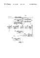
- FIG. 1is a functional block diagram illustrating a first embodiment of the diagnostic system according to this invention
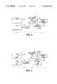
- FIG. 2is a functional block diagram showing a second embodiment of a diagnostic system according to this invention.
- FIG. 3is a functional block diagram showing a third embodiment of a diagnostic system according to this invention.
- FIG. 4is a functional block diagram showing a fourth embodiment of a diagnostic system according to this invention.
- FIG. 5is a functional block diagram showing a fifth embodiment of a diagnostic system according to this invention.
- FIG. 6is a functional block diagram showing a sixth embodiment of a diagnostic system according to this invention.
- FIG. 7is a functional block diagram showing a seventh embodiment of a diagnostic system according to this invention.
- FIG. 8is a workflow diagram illustrating an exemplary system workflow according to this invention.
- FIG. 9is a continuation of the workflow diagram of FIG. 8.
- FIG. 10is a flowchart outlining one exemplary embodiment of a method for diagnosing system faults in accordance with this invention.
- the diagnostic systems of this inventionare invoked.
- the diagnosis routinecan be initiated by the machine itself or can be initiated by a user or other operator, or by a diagnostic server residing on a distributed network.
- the first step to diagnosing/predicting a system problemis to collect and analyze relevant machine data.
- Such dataincludes, but is not limited to, control data such as commands issued by system and subsystem controllers, scheduling and timing data, set-point and actuator data, sensor data, state estimate data and so on; diagnostic data such as fault counts, error counts, event counts, warning and interlock counts, calibration data, device set-up data, high frequency service item information, service history data, machine history data and so on, virtual sensor readings, or job related data such as copy counts, percentage area coverage, document size and type and the like.
- the datacould also include environmental conditions such as temperature and humidity of the operating environment, and machine usage information such as, for example, the type and frequency of machine usage, and machine configuration information. This data collection can occur in real time, for example, as the user is processing documents, or, during a special diagnostic “stress mode” or test mode, where the document processing system is exercised appropriately to extract useful diagnostic information that may otherwise be unavailable in the normal machine operation mode.
- the data collectioncan occur on an ongoing basis before service of the machine is attempted, or even when the machine is in a limp-along mode.
- the informationmay be obtained from the machine itself, or from one or more servers connected to the machine in a distributed network that store information pertinent to the machine being diagnosed.
- fleet-wide machine data resident in population databases or serversmay also be used in the diagnostic/prognostic analysis.
- This datais then forwarded to a diagnostic inference engine that analyzes the data and provides an initial diagnosis. If this diagnosis proves to be incomplete, the image quality analysis module is activated. Then, based on the results of the initial diagnosis, a determination is made as to what test prints are to be scanned and what image quality tests are to be performed.
- a set of pre-defined test patternsare then printed and subsequently scanned, or scanned directly, depending on whether the test patterns are stored internal to the machine being diagnosed, are available on a networked drive, or, are available in hardcopy form.
- This scanningcan be accomplished by using an external scanner, or by using a scanner incorporated into the document processing system.
- the scanning processcan be user mediated, or can be completely automated if the device includes a media transport mechanism to re-circulate a document to the device's scan path from the output path, such as, for example, from the output of the fuser module in a printer.
- the directly scanned image, or the printed and subsequently scanned imageis then analyzed by the image quality analysis module to detect and identify the presence of defects in the image and to determine image quality parameters.
- the results of the image quality/defect analysisare then fed to the diagnostic engine which refines its original diagnosis based on the new information received from the printed test pattern(s), and produces a final list of failures, suspected failures, or impending failures.
- the diagnostic enginewhich refines its original diagnosis based on the new information received from the printed test pattern(s), and produces a final list of failures, suspected failures, or impending failures.
- the machinemay be queried or controlled to obtain additional data from the machine such as, for example, by running additional tests.
- additional test patternsmay also be printed, scanned and analyzed at any time during the process, if necessary.
- the extent of the diagnosis processcan limited, for example, based on a predefined user authorization scheme and corresponding user identification.
- the results from the diagnostic engineare then conveyed to, for example, the customer or the customer service engineer. Where possible, the system attempts to repair itself. Otherwise, either the customer or a service engineer is contacted to undertake the appropriate repair action. In addition, a request could be forwarded automatically to a parts/consumables supplier. Once the machine has been repaired, a verification process is initiated to ensure the repairs were successful. Finally, the results of the diagnostic/prognostic analysis and the repair procedures are logged into a machine service log or one or more databases.
- FIG. 1illustrates one exemplary embodiment of the diagnostic system 10 .
- the diagnostic system 10comprises a document processing system 100 , such as a xerographic marking engine, an ink jet printer, a lithographic printer, a color or black and white printer, a color or black and white photocopier, a color or black and white scanner, a facsimile machine, or the like, a scanner 110 , an image quality analysis circuit 120 , a job control circuit 130 , a system/subsystem controller(s) 140 , one or more sensors 150 , a memory 160 , one or more virtual sensors 170 , a diagnostic pre-processor circuit 180 , a diagnostic inference engine circuit 190 , a diagnostic controller 200 , a knowledge server/database 230 , a local user interface 210 and a remote user interface 220 , all interconnected by links 25 .
- a document processing system 100such as a xerographic marking engine, an ink jet printer, a lithographic printer, a color or
- any one of, or a portion of the components of the diagnostic systemcan be located anywhere including on the actual document processing system itself, on a distributed network, or a collocated or remote diagnostics location.
- links 25can be wired or wireless links or any other known or later developed element(s) that is capable of supplying electronic data to and from the connected elements.
- links 25can be any one of, or combination of, a direct serial connection, a distributed network such as an intranet, a local area network, a metropolitan area network, a wide area network, a satellite communication network, an infrared communication network, the Internet, or the like.
- the virtual sensor 170are based on quantitative analysis of machine signals, such as, for example, ground return line currents, in order to extract useful diagnostic information from the signals. Alternatively, they could be counters that keep track of signal changes, fault counts, calibration runs, pages processed, etc. Depending on the document processing system, the nature of the failures to be diagnosed, and the nature of the available information, a variety of different techniques of varying complexity can be used for the virtual sensors 170 .
- Such techniquesinclude but are not limited to, threshold analysis, statistical analysis, such as means and variance analysis, signature analysis, pattern analysis, trend analysis, event sequence analysis, timing analysis, rate analysis, counting mechanisms, such as, for example, signal change counters, state estimation analysis, and the like.
- datais collected from one or more of the job control circuit 130 , the system/subsystem controllers 140 , the one or more sensors 150 , the one or more virtual sensors 170 , and the memory 160 .
- This datais derived from the operational characteristics of the document processing system 100 and forwarded to the diagnostic pre-processing circuit 180 .
- both the individual machine information and the fleet-wide population statisticsmay be obtained from the knowledge server/database 230 .
- the pre-processing circuit 180collects the machine and job data from the various sensors, controllers, or the like, and translates this data into a format recognizable by the diagnostic inference engine circuit 190 .
- this pre-processingmay involve discretization of analog data received from one or more sensors into qualitative values. Alternatively, it may involve translating machine signals into discrete event sequences as described in U.S. Application No. 60/154,016, that can be recognized by the diagnostic inference engine circuit 190 .
- the diagnostic inference engine circuit 190performs the task of reasoning with the multiple sources of diagnostic/prognostic information and isolating the root of the cause for the failure, actual or impending.
- the diagnostic inference engine circuit 190can be based on one or more of the following diagnostic/prognostic technologies, for example, model based diagnosis, discrete event systems diagnosis, bayesian networks, causal networks, neural networks, artificial intelligence, rule-based systems, expert systems, fuzzy logic analysis, and/or look-up tables. Therefore, based on the analysis of the data output by the pre-processor circuit 180 , the diagnostic inference engine circuit 190 determines the list of components that have failed, are suspected to have failed or estimated to fail.
- the diagnostic inference engine circuit 190determines an initial diagnosis of the document processing system 100 based on the data received from the various sensors, the virtual sensors, the controllers, and the memory units via the pre-processor circuit 180 . Based on this initial diagnosis, and in cooperation with the diagnostic controller 200 , the initial diagnosis is forwarded to one or more of the local user interface 210 or the remote user interface 220 , and displayed. Additionally, the diagnostic controller 200 initiates a print and scan sequence to determine image quality parameters and/or detect image defects. In particular, the diagnostic controller decides, based on the initial diagnosis, what test prints are to be scanned and what image quality parameters are to be determined and/or what defects are to be recognized and characterized.
- the document processing system 100is then be directed to produce one or more test pattern prints, stored either in its internal memory, or on a network drive in a distributed network environment.
- the test pattern printsare then forwarded to the scanner 110 for digitizing.
- the customer, the customer service engineer, or the likecan directly scan the hard copy test prints.
- the scanner 110can be collocated with the document processing system 100 or, alternatively, be a stand-alone device or incorporated into, for example, a dedicated scanner and diagnostic system. Also, the printing and scanning process can be completely automated if a transport mechanism is available to re-circulate the printed test pattern to the scanner, for example, in the case where the scanner is incorporated into the document processing system being diagnosed.
- the digitized images of the test patterns produced by scanner 110are forwarded to the image quality analysis circuit 120 .
- the image quality analysis circuit 120analyzes the image, using commonly known image processing techniques such as, for example, Fourier transform analysis, histogramming, edge detection, 1-D projections, segmentation, classification, artifact detection, FIR filtering, morphological analysis, wavelet analysis and statistical analysis pattern recognition techniques, neural networks, or the like, to evaluate image quality parameters and/or identify defects in the image(s).
- image processingcan compensate via a calibration circuit for any defects introduced by the scanner., and then determine the image quality parameters and/or detect the presence of any defects in the printed document.
- the image quality defect recognition circuit 120detects the presence of one or more of a set of pre-defined defects in the input scanned image and/or calculates the values of one or more image quality parameters.
- defects and parametersinclude, but are not limited to, lines, bands, streaks, spots, mottle, halo, splatter, light images, dark images, blank images, deletions, background ink contamination, graininess, ghosting, skew, registration defects, color balance, color registration, color variation within a page, print-to-print variation, inboard-outboard variation, loss of a tone-reproduction, line width, edge width, line density, line edge, line shape, sharpness, contours, reload, pixel to pixel placement defects, and the like.
- image quality analysis and defect recognitionare accomplished through the use of image processing and/or pattern recognition algorithms such as those described in copending applications Ser. Nos. 09/450,185; 09/450,183; 09/450,182; 09/450,181; 09/450,180; and 19/450,177, incorporated herein by reference in their entirety.
- the image quality defect recognition 120may also have an optical character recognition component, bar code or glyph recognition component that ensures that the correct test patterns have been scanned and scanned in the right sequence and orientation. If the correct test pattern was not scanned, in cooperation with the diagnostic controller 200 , the user can be redirected to reprint and re-scan the right prints.
- the image quality defect recognition circuit 120outputs a set of metrics that qualify and quantify the one or more defects, and/or image quality parameters.
- inputmay also be obtained from the customer, and/or the customer service engineer via the user interface 210 or 220 , for characterizing the defects observed either in the test prints, or in the customer prints. This additional input from the user can be used to augment and/or verify the results of the image quality analysis module, and/or to reduce the number of test prints to be scanned and the number of defects to be characterized, similar to the manner in which the results of the initial diagnosis based on machine data are used.
- the results of the defect recognitionare forwarded to the diagnostic pre-processor 180 , via link 25 .
- the pre-processingin this case may involve comparisons of the results of the image quality analysis from two or more scanned images to check, for example, the presence of defects in all prints, the registration of a defect with respect to a page, the effects of rotating/magnifying a test pattern, and so on.
- the pre-processor circuit 180now having information pertaining to the image quality, forwards this additional information to the diagnostic inference engine circuit 190 .
- the diagnostic inference engine circuit 190refines the initial diagnosis and outputs the results of this diagnosis to one or more of the local user interface 210 and/or the remote user interface 220 .
- the diagnostic inference engine circuit 190can forward to either one of the user interfaces information indicating that the machine is operating acceptably, or that one or more failures are predicted to occur, or have occurred.
- the diagnostic inference engine circuit 190outputs information pertaining to the operational status of the document processing system.
- the listincludes, but is not limited to, status information about the system, a list of one or more failed components, information pertaining to components that are predicted to fail, or the like.
- These resultsare output and displayed locally on the user interface of the system and/or a local diagnostic server on the customer side and/or transmitted remotely to any entity needing the information, such as a customer service engineer, a diagnostic server, a part supplier, or the like.
- the results of the diagnostic inference engine circuit 190need not be limited to visual notifications, but can also include audio notifications or any means obvious to one of ordinary skill in the art to notify the appropriate party. Examples of such notification methods include notifications via e-mail, paging, cellular phones, a web page, or the like.
- the results of the diagnostic/prognostic analysismay also be stored in machine history logs and/or in one or more databases or servers.
- the diagnostic routineis complete. However, if there are any errors, or predicted errors determined in the refined diagnosis step, the diagnostic system 10 performs one or more of contacting a customer or customer service engineer for commencement of repair action. Alternatively, the diagnostic system 10 communicates with the document processing system 100 to invoke any appropriate auto-repair procedure such as machine set-up procedures, color balancing, color calibration, placing the machine in a low productivity mode, etc.
- the results of the automated repair proceduressuch as, for example, the machine parameters changed during a set-up procedure, are displayed on the user interface of the system, and/or a diagnostic server and/or transmitted remotely to a customer service engineer and, in addition, stored in the machine history logs.
- the machine's operationis verified and, if correct, the diagnostic routine completed.
- the customeris guided through a repair procedure.
- the systemmay be equipped with a security system that allows different classes of customers, such as the end-user, key operator, and system administrator different levels of access to perform repair actions.
- the end-usermay have access to replace consumables, but no access to run a color calibration routine, or adjust machine setpoints.
- the key operatormay have access to run a calibration routine and replace consumables, but denied access to change set-point values in the systems internal memory. All users may on the other hand, have permissions to place a service call
- machine data analysisprecedes the image quality analysis.
- the machine data analysis and the image quality analysiscan take place in any order, or even in parallel, depending on the specific system implementation.
- the machinemay be queried or controlled to obtain additional data from the machine such as, for example, by running additional tests.
- additional test patternsmay also be scanned and analyzed at any time during the process if necessary.
- FIGS. 2-7illustrate various exemplary embodiments of the locations of the components of the diagnostic/prognostic system 10 based on various considerations such as cost, network bandwidth, processor requirements, memory requirements, latency, data transmission rates, firewall and security issues, marketing considerations, or the like.
- FIG. 2illustrates an exemplary embodiment where most of the diagnostics are performed in the document processing system itself, however, the display and notification information can be communicated anywhere.
- the copier 300includes the image quality analysis circuit 120 and the diagnostic inference engine circuit 190 .
- the printer 400comprises the image quality analysis circuit 120 and the diagnostic inference engine circuit 190 .
- the printer 400communicates with the scanner 110 to digitize one or more test patterns created by the printer 400 .
- the copier 300may also communicate with the scanner 110 .
- the local diagnostic server 500is located on the copier 300 and printer 400 side of the firewall 50 while, in this exemplary embodiment, the diagnostic server 700 is located on the opposite side of the firewall 50 , and the portable work station 600 may be on either side of the firewall 50 .
- FIG. 3illustrates a second exemplary embodiment where the diagnostic computation is carried out on a local diagnostic server at, for example, the customer site.
- the image quality analysis circuit 120is located in the copier 310 or in the printer 410 , which is connected to the scanner 110 , and the diagnostic inference engine circuit 190 is located within the local diagnostic server 510 .
- the scanned image datawhich may be of high bandwidth, does not need to be transported across the customer's network. Therefore, the remainder of the information needed by the diagnostic engine, i.e., all the relevant machine data, should be transmitted to the local server, either in real-time, or stored in memory, such as the memory 160 , and then transmitted to the server.
- the copier 310may also communicate with the scanner 110 where it is necessary to use an external scanner.
- the local diagnostic server 510is located on the copier 310 and printer 410 side of the firewall 50 while, in this exemplary embodiment, the diagnostic server 710 is located on the opposite side of the firewall 50 , and the portable work station 610 may be on either side of the firewall 50 .
- the local diagnostic serverhouses the image quality analysis circuit 120 and the diagnostic inference engine circuit 190 .
- the scanner 110is connected directly to the local diagnostic server 520 .
- the copier 320 and printer 420do not house any of the diagnostic algorithms.
- the copier 320may be connected to an external scanner 110 , if necessary.
- the local diagnostic server 520is located on the copier 320 and printer 420 side of the firewall 50 while, in this exemplary embodiment, the diagnostic server 720 is located on the opposite side of the firewall 50 , and the portable work station 620 may be on either side of the firewall 50 .
- FIG. 5illustrates another exemplary embodiment in which the diagnostic inference engine circuit 190 is located in the portable workstation 630 , that could be on either side of the firewall 50 .
- the copier 330 and the printer 430which additionally are, or can be connected to the scanner, comprise the image quality analysis circuit 120 .
- the image quality analysis circuit 120may reside in the local diagnostic server 530 .
- the local diagnostic server 530is located on the copier 330 and printer 430 side of the firewall 50 while, in this exemplary embodiment, the diagnostic server 730 is located on the opposite side of the firewall 50 , and the portable work station 630 may be on either side of the firewall 50 .
- FIG. 6illustrates another exemplary embodiment where the image quality analysis is on the document processing system or on the local server, and the diagnostic inference engine is part of a diagnostic server located on the opposite side of the firewall 50 .
- the copier 340includes an image quality analysis circuit 120
- the printer 440includes the image quality analysis circuit 120 .
- the printer, and optionally the copierare connected to the scanner 10 .
- the local diagnostic server 540includes an image quality analysis circuit 120
- the diagnostic server 740includes a diagnostic inference engine circuit 190 .
- the image quality analysis circuitis located on the document processing system or on the local server, it can be appreciated that the circuit can also reside on the diagnostic server along with the diagnostic inference engine.
- the portable workstation 640can be on either side of the firewall 50 , but in this case, does not include the diagnostic inference engine.
- FIG. 7illustrate an exemplary embodiment where both the image quality analysis circuit and the diagnostic inference engine can be implemented in a separate “image quality diagnostic tester.”
- This image quality diagnostic testermay also include an scanner.
- the diagnostic testercan be connected to the document processing system via a local connection medium, such as a serial link, the ethernet or any other well known or later developed wired or wireless link. Additionally, the diagnostic tester can be connected to the portable workstation 650 and/or the diagnostic server 750 outside the firewall 50 .
- this embodimentincludes copier 350 , printer 450 , the diagnostic tester 555 , which includes the diagnostic inference engine circuit 190 , the image analysis circuit 120 , scanner 110 , and, optionally, a local diagnostic server 550 , the firewall 50 and the diagnostic server 750 .
- FIGS. 8 and 9illustrate an exemplary workflow diagram showing data flow between the various components of the diagnostic/prognostic system.
- controlbegins in step S 1 where unsatisfactory image quality has been detected.
- step S 2the image quality diagnosis is invoked.
- step S 4the machine data service is invoked to acquire machine data as well as optionally perform additional tests to derive additional machine data.
- step S 6the machine tests are run.
- step S 8the acquired data is preprocessed and stored in a database.
- step S 10the first phase diagnosis is run on the machine data and an initial diagnosis/prognosis is obtained.
- step S 12a determination is made as to which image quality tests should be performed and which test patterns are to be scanned.
- step S 14the determined test patterns are retrieved, printed and scanned.
- the scanned imagesare then acquired in step S 16 .
- step S 20the scanned image data is forwarded to the image quality analysis circuit for image quality analysis and defect recognition.
- step S 22the results of the image quality analysis, i.e, the image quality defect data and the image quality parameter data, are preprocessed.
- step S 24the phase 2 diagnosis/prognosis is run and the list of failures that have occurred, or are impending, are determined.
- step S 26the repair action is planned and recommended repair actions forwarded to the database in conjunction with all of the final and the intermediate results of the diagnostic/prognostic analysis.
- the scanned image data, the performed image quality tests and the test patterns usedmay all be stored in the database.
- step S 28an autonomous repair sequence is initiated.
- the data pertaining to the automated repair actionsuch as, for example, the setpoint changes, are written to the database.
- step S 30where a customer repair action is recommended, the necessary or appropriate information is sent to the customer.
- the customerrepairs the machine.
- step S 32a call for service is made based on the recommended repair action. This includes forwarding the call to a service monitoring system which dispatches a service call in step S 34 to a customer service engineer and/or forwards a service call in step S 36 to a portable workstation.
- step S 38the customer service engineer repairs the machine.
- step S 40the repair action and the satisfactory operation of the machine are verified and the diagnostics/prognostics sequence ends.
- FIG. 10illustrates an exemplary embodiment of one method for diagnosing/predicting document processing system failures in accordance with this invention.
- Controlbegins in step S 100 and continues to step S 110 .
- the diagnostic routineis initiated.
- machine data and job dataare collected and stored.
- the diagnostic inference engineoperates on one or more of the machine and job data to obtain an initial diagnostics.
- Controlthen continues to step S 140 .
- step 140the test patterns and the corresponding image quality analysis tests to be performed are determined.
- step 150test patterns are printed and scanned.
- step S 160a determination is made as to whether the correct test patterns have been scanned, and whether they have been scanned in the correct sequence. If the correct test patterns have not scanned, control continues to step S 170 where the user is requested to scan the prints correctly. Control then returns to step S 150 . Otherwise, control jumps to step S 180 .
- step S 180the image quality analysis is initiated to identify image defects.
- step S 190the diagnostic inference engine refines this initial diagnosis based on one or more of the found image defects and the machine and job data.
- step S 200the results of the diagnosis are output and/or stored. Control then continues to step S 210 .
- step S 210a determination is made whether the machine is operating correctly. If machine failures were found to have occurred, control continues to step S 220 . In steps S 220 and S 230 , the appropriate repair action is determined and one or more of a customer, a customer service engineer, or an automatic machine repair action are commenced. Then, in step S 240 , the operation of the machine is verified. Control then returns to step S 210 .
- controljumps to step S 250 where the diagnostic routine ends. Control then continues to step S 260 where the control sequence ends.
- the diagnostic systemis preferably implemented either on a single program general purpose computer or separate program general purpose computer.
- the diagnostic systemcan also be implemented on a special purpose computer, a programmed microprocessor or microcontroller and peripheral integrated circuit element, an ASIC, or other integrated circuit, a digital signal processor, a hard-wired electronic or logic circuit such as a discreet element circuit, a programmable logic device such as a PLD, PLA, FPGA, PAL, or the like.
- any device capable of implementing a finite state machinethat is in turn capable of implementing the a flowcharts shown in FIGS. 8-10 can be used to implement the diagnostic system.
- the disclosed methodmay be readily implemented in software using object or object-oriented software development environments that provide portable source code that can be used on a variety of computer, workstation and/or personal digital assistant hardware platforms.
- the disclosed diagnostic systemmay be implemented partially or fully in a hardware using standard logic circuits or a VLSI design. Whether software or hardware is used to implement the systems in accordance with this invention is dependent on the speed and/or efficiency requirements of the system, the particular function, and the particular software or hardware systems or microprocessor or microcomputer systems being utilized.
- the disclosed methodsmay be readily implemented as software executed on a programmed general purpose computer, a special purpose computer, a microprocessor, or the like.
- the methods and systems of this inventioncan be implemented as a routine embedded on a personal computer such as a Java® or CGI script, as a resource residing on a server or graphics workstation, as a routine embedded in a diagnostic system, personal digital assistant interface, dedicated handheld device, or the like.
- the diagnostic systemcan also be implemented by physically incorporating the system and method into a software and/or a hardware system, such as the hardware and software systems of a workstation or dedicated diagnostic system.
Landscapes
- Engineering & Computer Science (AREA)
- Signal Processing (AREA)
- Health & Medical Sciences (AREA)
- Biomedical Technology (AREA)
- General Health & Medical Sciences (AREA)
- Multimedia (AREA)
- Microelectronics & Electronic Packaging (AREA)
- Physics & Mathematics (AREA)
- General Physics & Mathematics (AREA)
- Human Computer Interaction (AREA)
- Facsimiles In General (AREA)
- Control Or Security For Electrophotography (AREA)
- Accessory Devices And Overall Control Thereof (AREA)
- Management, Administration, Business Operations System, And Electronic Commerce (AREA)
Abstract
Description
Claims (40)
Priority Applications (4)
| Application Number | Priority Date | Filing Date | Title |
|---|---|---|---|
| US09/464,596US6665425B1 (en) | 1999-12-16 | 1999-12-16 | Systems and methods for automated image quality based diagnostics and remediation of document processing systems |
| DE60039020TDE60039020D1 (en) | 1999-12-16 | 2000-12-14 | Systems and methods for automated image quality based diagnostics and refurbishment of document processing systems |
| EP00311191AEP1109395B1 (en) | 1999-12-16 | 2000-12-14 | Systems and methods for automated image quality based diagnostics and remediation of document processing systems |
| JP2000384233AJP2001245091A (en) | 1999-12-16 | 2000-12-18 | Method and system for automatic diagnosis and repair on image quality basis in document processing system |
Applications Claiming Priority (1)
| Application Number | Priority Date | Filing Date | Title |
|---|---|---|---|
| US09/464,596US6665425B1 (en) | 1999-12-16 | 1999-12-16 | Systems and methods for automated image quality based diagnostics and remediation of document processing systems |
Publications (1)
| Publication Number | Publication Date |
|---|---|
| US6665425B1true US6665425B1 (en) | 2003-12-16 |
Family
ID=23844542
Family Applications (1)
| Application Number | Title | Priority Date | Filing Date |
|---|---|---|---|
| US09/464,596Expired - LifetimeUS6665425B1 (en) | 1999-12-16 | 1999-12-16 | Systems and methods for automated image quality based diagnostics and remediation of document processing systems |
Country Status (4)
| Country | Link |
|---|---|
| US (1) | US6665425B1 (en) |
| EP (1) | EP1109395B1 (en) |
| JP (1) | JP2001245091A (en) |
| DE (1) | DE60039020D1 (en) |
Cited By (121)
| Publication number | Priority date | Publication date | Assignee | Title |
|---|---|---|---|---|
| US20010015824A1 (en)* | 2000-02-21 | 2001-08-23 | Toshiba Tec Kabushiki Kaisha | Image processing apparatus |
| US20010037505A1 (en)* | 2000-04-27 | 2001-11-01 | Lg Electronics Inc. | TV and control method of the same |
| US20020008883A1 (en)* | 2000-05-02 | 2002-01-24 | Ricoh Company, Ltd. | Method and apparatus for data communications capable of automatically sending a maintenance request |
| US20020048052A1 (en)* | 2000-10-25 | 2002-04-25 | Nec Corporation | Document input/output system and set information registration method for use thereby |
| US20020060805A1 (en)* | 2000-11-21 | 2002-05-23 | Makoto Tomita | Print data processing apparatus, print control method, and print control program |
| US20020093525A1 (en)* | 2000-09-27 | 2002-07-18 | Seiko Epson Corporation | User support |
| US20030065807A1 (en)* | 2001-09-28 | 2003-04-03 | Hiroshi Satomi | Server apparatus and control method therefor |
| US20030076523A1 (en)* | 2001-09-25 | 2003-04-24 | Akio Ito | Diagnosing method and diagnosing system of print picture quality of image processing apparatus |
| US20030118353A1 (en)* | 2001-12-20 | 2003-06-26 | Baller Eric Henry | Method and apparatus for managing intelligent assets in a distributed environment |
| US20030142985A1 (en)* | 2002-01-30 | 2003-07-31 | Xerox Corporation | Automated banding defect analysis and repair for document processing systems |
| US20030193684A1 (en)* | 2002-04-10 | 2003-10-16 | Kendall David R. | Method and system for diagnosing printing defects |
| US20030231361A1 (en)* | 2002-03-28 | 2003-12-18 | Brother Kogyo Kabushiki Kaisha | Communication system |
| US20040025082A1 (en)* | 2002-07-31 | 2004-02-05 | Roddy Nicholas Edward | Method and system for monitoring problem resolution of a machine |
| US20040088601A1 (en)* | 2002-10-31 | 2004-05-06 | General Electric Company | Method, system and program product for establishing a self-diagnosing and self-repairing automated system |
| US20040122307A1 (en)* | 2001-11-21 | 2004-06-24 | Shraga Rottem | Method and system for enhancing the quality of device images |
| US20040133398A1 (en)* | 2003-01-08 | 2004-07-08 | Dell Products L.P. | System and method for interpreting sensor data utilizing virtual sensors |
| US20040169745A1 (en)* | 2002-01-17 | 2004-09-02 | Matthias Franz | Method and device for recognizing or displaying image defects in image recording systems |
| US20040199361A1 (en)* | 2003-04-01 | 2004-10-07 | Ching-Shan Lu | Method and apparatus for equipment diagnostics and recovery with self-learning |
| US20040213435A1 (en)* | 2002-06-12 | 2004-10-28 | Seiko Epson Corporation | Method of evaluating image pattern output accuracy |
| US20040264771A1 (en)* | 2003-06-30 | 2004-12-30 | Gaurav Sharma | Systems and methods for associating color profiles with a scanned input image using spatial attributes |
| US20050044295A1 (en)* | 2003-08-21 | 2005-02-24 | Microsoft Corporation | Electronic ink processing |
| US6885469B1 (en)* | 1999-06-17 | 2005-04-26 | Murata Kikai Kabushiki Kaisha | Image processing device |
| US20050152616A1 (en)* | 2004-01-09 | 2005-07-14 | Bailey James R. | Method and apparatus for automatic scanner defect detection |
| US20050169523A1 (en)* | 2003-12-05 | 2005-08-04 | Ikuo Hayaishi | Image processing with information associated with image data |
| US20050206952A1 (en)* | 2004-03-22 | 2005-09-22 | Fuji Xerox Co., Ltd. | Image processing device, processing system and image processing method |
| US6954678B1 (en)* | 2002-09-30 | 2005-10-11 | Advanced Micro Devices, Inc. | Artificial intelligence system for track defect problem solving |
| US20050262394A1 (en)* | 2004-04-21 | 2005-11-24 | Fuji Xerox Co., Ltd. | Failure diagnosis method, failure diagnosis apparatus, conveyance device, image forming apparatus, program, and storage medium |
| US20050286742A1 (en)* | 2004-06-28 | 2005-12-29 | Xerox Corporation | Dynamic test pattern composition for image-analysis based automatic machine diagnostics |
| US20060093205A1 (en)* | 2004-10-29 | 2006-05-04 | Bryll Robert K | System and method for automatically recovering video tools in a vision system |
| US20060103899A1 (en)* | 2004-11-17 | 2006-05-18 | Xerox Corporation | Image quality defect detection from image quality database |
| US20060119877A1 (en)* | 2004-12-02 | 2006-06-08 | Xerox Corporation | System and method for real-time detection of development defects for an image output device |
| US20060147117A1 (en)* | 2003-08-21 | 2006-07-06 | Microsoft Corporation | Electronic ink processing and application programming interfaces |
| US20060215231A1 (en)* | 2005-03-24 | 2006-09-28 | Borrey Roland G | Systems and methods of processing scanned data |
| US20060221402A1 (en)* | 2005-03-31 | 2006-10-05 | Hubin Jiang | Imaging system with quality audit capability |
| US20060238780A1 (en)* | 2005-04-20 | 2006-10-26 | Dennison Carl M | Validation of a print verification system |
| US20070003109A1 (en)* | 2005-06-30 | 2007-01-04 | Xerox Corporation | Automated image quality diagnostics system |
| US20070006050A1 (en)* | 2005-06-30 | 2007-01-04 | Xerox Corporation | Automatic notification of applicable bulletins and tags based on fault analysis |
| US20070027951A1 (en)* | 2000-07-25 | 2007-02-01 | Tetsuro Motoyama | Method and system for diagnosing, collecting information and servicing a remote system |
| US20070127044A1 (en)* | 2005-12-02 | 2007-06-07 | Ryobi Ltd. | Print quality checking system and print quality checking method |
| US20070127057A1 (en)* | 2005-12-01 | 2007-06-07 | Lexmark International, Inc. | Job status tracking and notification system |
| US20070223023A1 (en)* | 2006-03-27 | 2007-09-27 | Fujifilm Corporation | Printing apparatus and printing system |
| US20070237399A1 (en)* | 2006-04-07 | 2007-10-11 | Fuji Xerox Co., Ltd. | Failure analysis system, failure analysis method, and program product for failure analysis |
| JP2007329779A (en)* | 2006-06-09 | 2007-12-20 | Fuji Xerox Co Ltd | Defect classification system, image forming apparatus and defect classification program |
| US20080007746A1 (en)* | 2006-03-22 | 2008-01-10 | Kabushiki Kaisha Toshiba | Image Process System, Image Process Method and Image Process Program |
| US20080137914A1 (en)* | 2006-12-07 | 2008-06-12 | Xerox Corporation | Printer job visualization |
| US20080162993A1 (en)* | 2006-12-27 | 2008-07-03 | Samsung Electronics Co., Ltd | Image forming device to perform a system diagnosis and method thereof |
| US20080178067A1 (en)* | 2007-01-19 | 2008-07-24 | Microsoft Corporation | Document Performance Analysis |
| US20080266578A1 (en)* | 2007-04-26 | 2008-10-30 | Konica Minolta Business Technologies, Inc. | Image processing apparatus, workflow testing method and workflow testing program |
| US20090019271A1 (en)* | 2007-07-11 | 2009-01-15 | Canon Kabushiki Kaisha | Information processing apparatus, information processing method, and storage medium |
| US20090041370A1 (en)* | 2007-08-09 | 2009-02-12 | Xerox Corporation | Background noise detection on rendered documents |
| US20090066994A1 (en)* | 2007-09-11 | 2009-03-12 | Xerox Corporation | Method and sytem for remote management of print devices |
| US20090066993A1 (en)* | 2007-09-11 | 2009-03-12 | Xerox Corporation | Remote print device management |
| US20090106363A1 (en)* | 2007-10-19 | 2009-04-23 | Oracle International Parkway | Intelligent collection of diagnostic data for communication to diagnosis site |
| US20090171879A1 (en)* | 2007-12-28 | 2009-07-02 | Software Ag | Systems and/or methods for prediction and/or root cause analysis of events based on business activity monitoring related data |
| US20090232521A1 (en)* | 2008-03-17 | 2009-09-17 | Canon Kabushiki Kaisha | Image forming apparatus, method of controlling the image forming apparatus, and storage medium |
| US20090268261A1 (en)* | 2008-04-24 | 2009-10-29 | Xerox Corporation | Systems and methods for implementing use of customer documents in maintaining image quality (iq)/image quality consistency (iqc) of printing devices |
| US20090274342A1 (en)* | 2008-04-30 | 2009-11-05 | Xerox Corporation | Printer characterization, monitoring and diagnosis using dynamic test patterns generated by sensing and analyzing customer documents |
| US7676703B2 (en) | 2006-06-09 | 2010-03-09 | Fuji Xerox Co., Ltd. | Failure diagnosis system, image forming apparatus, computer readable medium and data signal |
| WO2010063800A1 (en)* | 2008-12-03 | 2010-06-10 | Oce-Technologies B.V. | Reprographic system |
| US20100149560A1 (en)* | 2008-12-15 | 2010-06-17 | Xerox Corporation | Method for assessing synchronized print defects |
| US20100201997A1 (en)* | 2006-10-06 | 2010-08-12 | Michael Has | Method and system for the automatic processing of printing data for a printing operation |
| US20100238462A1 (en)* | 2009-03-17 | 2010-09-23 | Xerox Corporation | System and method for image quality analysis and diagnostics |
| US20100306056A1 (en)* | 2009-05-28 | 2010-12-02 | Xerox Corporation | System and method of remote machine servicing |
| US7937370B2 (en) | 2000-09-22 | 2011-05-03 | Axeda Corporation | Retrieving data from a server |
| US20110110565A1 (en)* | 2009-11-10 | 2011-05-12 | General Electric Company | Method and system for checking the diagnostic quality of a medical system |
| US7966418B2 (en) | 2003-02-21 | 2011-06-21 | Axeda Corporation | Establishing a virtual tunnel between two computer programs |
| US20110170134A1 (en)* | 2010-01-12 | 2011-07-14 | Kabushiki Kaisha Toshiba | Image forming apparatus and maintenance method of image forming apparatus |
| US8055758B2 (en) | 2000-07-28 | 2011-11-08 | Axeda Corporation | Reporting the state of an apparatus to a remote computer |
| US8060886B2 (en) | 2002-04-17 | 2011-11-15 | Axeda Corporation | XML scripting of SOAP commands |
| US8065397B2 (en) | 2006-12-26 | 2011-11-22 | Axeda Acquisition Corporation | Managing configurations of distributed devices |
| US8108543B2 (en) | 2000-09-22 | 2012-01-31 | Axeda Corporation | Retrieving data from a server |
| US8135817B2 (en) | 1998-11-17 | 2012-03-13 | Ricoh Company, Ltd. | Method and system for communicating with a device attached to a computer using electronic mail messages |
| US8140898B2 (en) | 2009-06-16 | 2012-03-20 | Oracle International Corporation | Techniques for gathering evidence for performing diagnostics |
| US8171343B2 (en) | 2009-06-16 | 2012-05-01 | Oracle International Corporation | Techniques for determining models for performing diagnostics |
| US20120274997A1 (en)* | 2011-04-29 | 2012-11-01 | Xerox Corporation | Process direction streak source diagnosis in printers |
| US8370479B2 (en) | 2006-10-03 | 2013-02-05 | Axeda Acquisition Corporation | System and method for dynamically grouping devices based on present device conditions |
| US8417656B2 (en) | 2009-06-16 | 2013-04-09 | Oracle International Corporation | Techniques for building an aggregate model for performing diagnostics |
| US8478861B2 (en) | 2007-07-06 | 2013-07-02 | Axeda Acquisition Corp. | Managing distributed devices with limited connectivity |
| US20130242354A1 (en)* | 2012-03-19 | 2013-09-19 | Ian Dewancker | Method for simulating impact printer output |
| US8612377B2 (en) | 2009-12-17 | 2013-12-17 | Oracle International Corporation | Techniques for generating diagnostic results |
| US8849586B1 (en) | 2007-11-30 | 2014-09-30 | Intellectual Assets Llc | Path classification and estimation method and system for prognosticating asset life |
| US8855954B1 (en) | 2007-11-30 | 2014-10-07 | Intellectual Assets Llc | System and method for prognosticating capacity life and cycle life of a battery asset |
| US8855375B2 (en) | 2012-01-12 | 2014-10-07 | Kofax, Inc. | Systems and methods for mobile image capture and processing |
| US8885229B1 (en) | 2013-05-03 | 2014-11-11 | Kofax, Inc. | Systems and methods for detecting and classifying objects in video captured using mobile devices |
| US8958605B2 (en) | 2009-02-10 | 2015-02-17 | Kofax, Inc. | Systems, methods and computer program products for determining document validity |
| US9058515B1 (en) | 2012-01-12 | 2015-06-16 | Kofax, Inc. | Systems and methods for identification document processing and business workflow integration |
| US9058580B1 (en) | 2012-01-12 | 2015-06-16 | Kofax, Inc. | Systems and methods for identification document processing and business workflow integration |
| US9137417B2 (en) | 2005-03-24 | 2015-09-15 | Kofax, Inc. | Systems and methods for processing video data |
| US9141926B2 (en) | 2013-04-23 | 2015-09-22 | Kofax, Inc. | Smart mobile application development platform |
| US9208536B2 (en) | 2013-09-27 | 2015-12-08 | Kofax, Inc. | Systems and methods for three dimensional geometric reconstruction of captured image data |
| US9311531B2 (en) | 2013-03-13 | 2016-04-12 | Kofax, Inc. | Systems and methods for classifying objects in digital images captured using mobile devices |
| US9336016B2 (en) | 2005-04-15 | 2016-05-10 | Microsoft Technology Licensing, Llc | Registration of applications and complimentary features for interactive user interfaces |
| US9355312B2 (en) | 2013-03-13 | 2016-05-31 | Kofax, Inc. | Systems and methods for classifying objects in digital images captured using mobile devices |
| US9386235B2 (en) | 2013-11-15 | 2016-07-05 | Kofax, Inc. | Systems and methods for generating composite images of long documents using mobile video data |
| CN105739257A (en)* | 2014-12-26 | 2016-07-06 | 京瓷办公信息系统株式会社 | Image forming apparatus |
| US9396388B2 (en) | 2009-02-10 | 2016-07-19 | Kofax, Inc. | Systems, methods and computer program products for determining document validity |
| US9483794B2 (en) | 2012-01-12 | 2016-11-01 | Kofax, Inc. | Systems and methods for identification document processing and business workflow integration |
| US20170013166A1 (en)* | 2014-03-27 | 2017-01-12 | Fujifilm Corporation | Printing system, method of generating halftone processing rule, method of acquiring characteristic parameter, image processing device, image processing method, halftone processing rule, halftone image, method of manufacturing printed material, inkjet printing system, and program |
| US9576272B2 (en) | 2009-02-10 | 2017-02-21 | Kofax, Inc. | Systems, methods and computer program products for determining document validity |
| US20170142192A1 (en)* | 2000-12-22 | 2017-05-18 | EK3 Technologes, Inc. | Narrowcast Media Content Distribution and Display System with Content Biasing Engine |
| US20170228612A1 (en)* | 2016-02-08 | 2017-08-10 | Fuji Xerox Co., Ltd. | Terminal device, diagnosis system and computer readable medium |
| US20170230517A1 (en)* | 2016-02-08 | 2017-08-10 | Fuji Xerox Co., Ltd. | Terminal device, diagnosis system, and non-transitory computer readable medium |
| US9747269B2 (en) | 2009-02-10 | 2017-08-29 | Kofax, Inc. | Smart optical input/output (I/O) extension for context-dependent workflows |
| US9760788B2 (en) | 2014-10-30 | 2017-09-12 | Kofax, Inc. | Mobile document detection and orientation based on reference object characteristics |
| US9769354B2 (en) | 2005-03-24 | 2017-09-19 | Kofax, Inc. | Systems and methods of processing scanned data |
| US9767354B2 (en) | 2009-02-10 | 2017-09-19 | Kofax, Inc. | Global geographic information retrieval, validation, and normalization |
| US9779296B1 (en) | 2016-04-01 | 2017-10-03 | Kofax, Inc. | Content-based detection and three dimensional geometric reconstruction of objects in image and video data |
| US10063719B2 (en) | 2015-12-24 | 2018-08-28 | S-Printing Solution Co., Ltd. | Image forming apparatus, guide providing method thereof, cloud server, and error analyzing method thereof |
| US10146795B2 (en) | 2012-01-12 | 2018-12-04 | Kofax, Inc. | Systems and methods for mobile image capture and processing |
| US20190007269A1 (en)* | 2017-06-30 | 2019-01-03 | Datamax-O'neil Corporation | Managing a fleet of devices |
| CN109213456A (en)* | 2017-06-30 | 2019-01-15 | 大数据奥尼尔公司 | Managing a batch of equipment |
| US10242285B2 (en) | 2015-07-20 | 2019-03-26 | Kofax, Inc. | Iterative recognition-guided thresholding and data extraction |
| US10375272B2 (en)* | 2016-03-22 | 2019-08-06 | Hewlett-Packard Development Company, L.P. | Stabilizing image forming quality |
| US10715683B2 (en) | 2017-01-25 | 2020-07-14 | Hewlett-Packard Development Company, L.P. | Print quality diagnosis |
| US10778690B2 (en) | 2017-06-30 | 2020-09-15 | Datamax-O'neil Corporation | Managing a fleet of workflow devices and standby devices in a device network |
| US10803350B2 (en) | 2017-11-30 | 2020-10-13 | Kofax, Inc. | Object detection and image cropping using a multi-detector approach |
| US10977594B2 (en) | 2017-06-30 | 2021-04-13 | Datamax-O'neil Corporation | Managing a fleet of devices |
| US11368697B1 (en)* | 2018-05-01 | 2022-06-21 | Google Llc | Adaptive image compression using a quality metric |
| US11523004B2 (en) | 2018-09-21 | 2022-12-06 | Hewlett-Packard Development Company, L.P. | Part replacement predictions using convolutional neural networks |
| US20240114096A1 (en)* | 2022-09-29 | 2024-04-04 | Canon Kabushiki Kaisha | Inspection system, inspection apparatus and method of controlling the same |
| EP4607283A1 (en)* | 2024-01-19 | 2025-08-27 | Canon Kabushiki Kaisha | Diagnostic apparatus, control method for the same, storage medium, and image forming apparatus |
Families Citing this family (18)
| Publication number | Priority date | Publication date | Assignee | Title |
|---|---|---|---|---|
| JP4585161B2 (en) | 2002-01-24 | 2010-11-24 | 株式会社東芝 | Inspection reservation system |
| JP2003291475A (en)* | 2002-03-29 | 2003-10-14 | Fuji Photo Film Co Ltd | Method for diagnosing image processing |
| EP1352741A3 (en)* | 2002-04-08 | 2008-07-23 | Eastman Kodak Company | Certified Proofing |
| JP4198020B2 (en) | 2002-10-14 | 2008-12-17 | オセ−テクノロジーズ ビーブイ | Selection mechanism in mobile terminals |
| EP1426833B1 (en)* | 2002-10-14 | 2014-11-12 | Océ-Technologies B.V. | Status monitoring of a plurality of image processing devices |
| DE10250180A1 (en)* | 2002-10-28 | 2004-05-13 | OCé PRINTING SYSTEMS GMBH | Graphical user interface and method for displaying a fault condition of an electrophotographic printing or copying system |
| US20050033834A1 (en)* | 2003-08-04 | 2005-02-10 | Nutt Letty B. | Diagnostic report transmission |
| CN1681033A (en) | 2004-04-06 | 2005-10-12 | 皇家飞利浦电子股份有限公司 | Fault correcting mechanism for CD player |
| JP4538845B2 (en)* | 2004-04-21 | 2010-09-08 | 富士ゼロックス株式会社 | FAILURE DIAGNOSIS METHOD, FAILURE DIAGNOSIS DEVICE, IMAGE FORMING DEVICE, PROGRAM, AND STORAGE MEDIUM |
| JP2006279177A (en)* | 2005-03-28 | 2006-10-12 | Fuji Xerox Co Ltd | Image forming apparatus and control system thereof |
| JP4887878B2 (en)* | 2006-04-07 | 2012-02-29 | 富士ゼロックス株式会社 | Failure diagnosis system and failure diagnosis method |
| JP6295612B2 (en)* | 2013-11-05 | 2018-03-20 | 株式会社リコー | Image forming system, image forming method, and program |
| CN109557894A (en)* | 2017-09-26 | 2019-04-02 | 同济大学 | Space flight large thin-wall element product processing quality diagnosis detection system |
| KR102116064B1 (en)* | 2018-01-29 | 2020-05-27 | (주)윈텍 | Plant diagnosis method using the same system |
| JP2020059240A (en)* | 2018-10-12 | 2020-04-16 | コニカミノルタ株式会社 | Image formation system |
| US11531970B2 (en)* | 2018-12-26 | 2022-12-20 | General Electric Company | Imaging modality maintenance care package systems and methods |
| KR20230053127A (en)* | 2021-10-14 | 2023-04-21 | 휴렛-팩커드 디벨롭먼트 컴퍼니, 엘.피. | Remote image diagnosis using inline scan module |
| CN116433670B (en)* | 2023-06-14 | 2023-08-29 | 浙江舶云科技有限公司 | Image quality detection method and detection system |
Citations (29)
| Publication number | Priority date | Publication date | Assignee | Title |
|---|---|---|---|---|
| US4071911A (en) | 1975-04-22 | 1978-01-31 | Continental Can Co. Inc. | Machine control system with machine serializing and safety circuits |
| US4086434A (en) | 1976-09-07 | 1978-04-25 | Leo P. Christiansen | Remote condition reporting system |
| US4583834A (en) | 1977-09-16 | 1986-04-22 | Ricoh Company, Ltd. | Copying apparatus |
| US5038319A (en) | 1989-04-24 | 1991-08-06 | Xerox Corporation | System for recording and remotely accessing operating data in a reproduction machine |
| US5057866A (en) | 1990-05-04 | 1991-10-15 | Xerox Corporation | Remotely accessible copier calculator |
| US5084875A (en) | 1989-12-13 | 1992-01-28 | Joseph Weinberger | System for automatically monitoring copiers from a remote location |
| EP0617696A1 (en) | 1991-12-17 | 1994-10-05 | Du Pont | Process for purifying hydrogen fluoride. |
| US5365310A (en) | 1993-07-30 | 1994-11-15 | Xerox Corporation | Remote diagnosis of copy quality defects |
| US5510896A (en) | 1993-06-18 | 1996-04-23 | Xerox Corporation | Automatic copy quality correction and calibration |
| US5510876A (en) | 1992-05-28 | 1996-04-23 | Ricoh Company, Ltd. | Control system for controlling the connection of an image forming apparatus through a control device by means of a communication control unit |
| US5515503A (en) | 1991-09-30 | 1996-05-07 | Mita Industrial Co. | Self-repair system for an image forming apparatus |
| US5580177A (en) | 1994-03-29 | 1996-12-03 | Hewlett-Packard Company | Printer/client network with centrally updated printer drivers and printer status monitoring |
| US5612902A (en) | 1994-09-13 | 1997-03-18 | Apple Computer, Inc. | Method and system for analytic generation of multi-dimensional color lookup tables |
| US5619307A (en) | 1994-07-07 | 1997-04-08 | Cannon Kabushiki Kaisha | Method of printing test pattern and apparatus for outputting test pattern |
| US5642202A (en) | 1994-12-01 | 1997-06-24 | Xerox Corporation | Scan image target locator system for calibrating a printing system |
| US5680541A (en) | 1991-12-16 | 1997-10-21 | Fuji Xerox Co., Ltd. | Diagnosing method and apparatus |
| US5694528A (en) | 1995-11-22 | 1997-12-02 | Xerox Corporation | Apparatus and method for diagnosing printing machine operation with facsimile transmitted dialog screens |
| US5727135A (en) | 1995-03-23 | 1998-03-10 | Lexmark International, Inc. | Multiple printer status information indication |
| US5748221A (en) | 1995-11-01 | 1998-05-05 | Xerox Corporation | Apparatus for colorimetry gloss and registration feedback in a color printing machine |
| US5761505A (en) | 1995-11-17 | 1998-06-02 | Hewlett-Packard Co. | System and method for automatically and reliably managing global resources in a computer network |
| EP0854632A2 (en) | 1997-01-20 | 1998-07-22 | Kabushiki Kaisha Toshiba | Image forming apparatus and method of forming images |
| US5786994A (en) | 1994-11-23 | 1998-07-28 | Imation Corp. | Performance monitoring system and method for a laser medical imager |
| EP0895399A1 (en) | 1997-07-30 | 1999-02-03 | Xerox Corporation | Improvements in or relating to servers |
| US5884118A (en) | 1996-11-26 | 1999-03-16 | Xerox Corporation | Printer having print output linked to scanner input for automated image quality adjustment |
| US5887216A (en)* | 1997-03-19 | 1999-03-23 | Ricoh Company, Ltd. | Method and system to diagnos a business office device based on operating parameters set by a user |
| US5893083A (en) | 1995-03-24 | 1999-04-06 | Hewlett-Packard Company | Methods and apparatus for monitoring events and implementing corrective action in a computer system |
| US5892451A (en) | 1996-10-09 | 1999-04-06 | Hewlett-Packard Company | Remote management of computing devices |
| US6023525A (en) | 1997-10-23 | 2000-02-08 | Xerox Corporation | Determining an optimal color space direction for selecting color modulations |
| US6023595A (en) | 1996-05-07 | 2000-02-08 | Canon Kabushiki Kaisha | Image processing apparatus capable of remotely diagnosing failed portion of image processing unit |
Family Cites Families (8)
| Publication number | Priority date | Publication date | Assignee | Title |
|---|---|---|---|---|
| JPS62138867A (en)* | 1985-12-13 | 1987-06-22 | Canon Inc | Image forming device operation display device |
| JPS62280961A (en)* | 1986-05-30 | 1987-12-05 | Canon Inc | Control system |
| JP3127931B2 (en)* | 1991-02-12 | 2001-01-29 | 富士ゼロックス株式会社 | Diagnosis method and prevention method for image recording apparatus and their systems |
| JPH07239825A (en)* | 1994-02-28 | 1995-09-12 | Canon Inc | Status reporting method and network system using the same |
| US6115509A (en)* | 1994-03-10 | 2000-09-05 | International Business Machines Corp | High volume document image archive system and method |
| JP3478634B2 (en)* | 1995-03-29 | 2003-12-15 | キヤノン株式会社 | Image forming system, image forming apparatus maintenance support apparatus, and image forming apparatus maintenance support method |
| JP3342644B2 (en)* | 1997-05-19 | 2002-11-11 | 富士通株式会社 | Printer / scanner, information processing system and storage medium |
| JPH11296329A (en)* | 1998-04-08 | 1999-10-29 | Sharp Corp | Network system |
- 1999
- 1999-12-16USUS09/464,596patent/US6665425B1/ennot_activeExpired - Lifetime
- 2000
- 2000-12-14EPEP00311191Apatent/EP1109395B1/ennot_activeExpired - Lifetime
- 2000-12-14DEDE60039020Tpatent/DE60039020D1/ennot_activeExpired - Lifetime
- 2000-12-18JPJP2000384233Apatent/JP2001245091A/enactivePending
Patent Citations (29)
| Publication number | Priority date | Publication date | Assignee | Title |
|---|---|---|---|---|
| US4071911A (en) | 1975-04-22 | 1978-01-31 | Continental Can Co. Inc. | Machine control system with machine serializing and safety circuits |
| US4086434A (en) | 1976-09-07 | 1978-04-25 | Leo P. Christiansen | Remote condition reporting system |
| US4583834A (en) | 1977-09-16 | 1986-04-22 | Ricoh Company, Ltd. | Copying apparatus |
| US5038319A (en) | 1989-04-24 | 1991-08-06 | Xerox Corporation | System for recording and remotely accessing operating data in a reproduction machine |
| US5084875A (en) | 1989-12-13 | 1992-01-28 | Joseph Weinberger | System for automatically monitoring copiers from a remote location |
| US5057866A (en) | 1990-05-04 | 1991-10-15 | Xerox Corporation | Remotely accessible copier calculator |
| US5515503A (en) | 1991-09-30 | 1996-05-07 | Mita Industrial Co. | Self-repair system for an image forming apparatus |
| US5680541A (en) | 1991-12-16 | 1997-10-21 | Fuji Xerox Co., Ltd. | Diagnosing method and apparatus |
| EP0617696A1 (en) | 1991-12-17 | 1994-10-05 | Du Pont | Process for purifying hydrogen fluoride. |
| US5510876A (en) | 1992-05-28 | 1996-04-23 | Ricoh Company, Ltd. | Control system for controlling the connection of an image forming apparatus through a control device by means of a communication control unit |
| US5510896A (en) | 1993-06-18 | 1996-04-23 | Xerox Corporation | Automatic copy quality correction and calibration |
| US5365310A (en) | 1993-07-30 | 1994-11-15 | Xerox Corporation | Remote diagnosis of copy quality defects |
| US5580177A (en) | 1994-03-29 | 1996-12-03 | Hewlett-Packard Company | Printer/client network with centrally updated printer drivers and printer status monitoring |
| US5619307A (en) | 1994-07-07 | 1997-04-08 | Cannon Kabushiki Kaisha | Method of printing test pattern and apparatus for outputting test pattern |
| US5612902A (en) | 1994-09-13 | 1997-03-18 | Apple Computer, Inc. | Method and system for analytic generation of multi-dimensional color lookup tables |
| US5786994A (en) | 1994-11-23 | 1998-07-28 | Imation Corp. | Performance monitoring system and method for a laser medical imager |
| US5642202A (en) | 1994-12-01 | 1997-06-24 | Xerox Corporation | Scan image target locator system for calibrating a printing system |
| US5727135A (en) | 1995-03-23 | 1998-03-10 | Lexmark International, Inc. | Multiple printer status information indication |
| US5893083A (en) | 1995-03-24 | 1999-04-06 | Hewlett-Packard Company | Methods and apparatus for monitoring events and implementing corrective action in a computer system |
| US5748221A (en) | 1995-11-01 | 1998-05-05 | Xerox Corporation | Apparatus for colorimetry gloss and registration feedback in a color printing machine |
| US5761505A (en) | 1995-11-17 | 1998-06-02 | Hewlett-Packard Co. | System and method for automatically and reliably managing global resources in a computer network |
| US5694528A (en) | 1995-11-22 | 1997-12-02 | Xerox Corporation | Apparatus and method for diagnosing printing machine operation with facsimile transmitted dialog screens |
| US6023595A (en) | 1996-05-07 | 2000-02-08 | Canon Kabushiki Kaisha | Image processing apparatus capable of remotely diagnosing failed portion of image processing unit |
| US5892451A (en) | 1996-10-09 | 1999-04-06 | Hewlett-Packard Company | Remote management of computing devices |
| US5884118A (en) | 1996-11-26 | 1999-03-16 | Xerox Corporation | Printer having print output linked to scanner input for automated image quality adjustment |
| EP0854632A2 (en) | 1997-01-20 | 1998-07-22 | Kabushiki Kaisha Toshiba | Image forming apparatus and method of forming images |
| US5887216A (en)* | 1997-03-19 | 1999-03-23 | Ricoh Company, Ltd. | Method and system to diagnos a business office device based on operating parameters set by a user |
| EP0895399A1 (en) | 1997-07-30 | 1999-02-03 | Xerox Corporation | Improvements in or relating to servers |
| US6023525A (en) | 1997-10-23 | 2000-02-08 | Xerox Corporation | Determining an optimal color space direction for selecting color modulations |
Non-Patent Citations (9)
| Title |
|---|
| "Combining Expert System and Analytical Redundancy Concepts for Fault-Tolerant Flight Control," David A. Handelman et al., Princeton University, J. Guidance, vol. 12, No. 1, Jan.-Feb. 1989, pp. 39-45. |
| "Fault Diagnosis in Dynamic Systems Using Analytical and Knowledge-based Redundancy-A Survey and Some New Resluts," Paul M. Frank, Automatica, vol. 26, 90 International Federation of Automatic Control, 1990, pp. 459-474. |
| "IQ Data Systems-revolutionizing the way . . . is measured, monitored, and controlled.", IQ Data Systems, http://www.iqds.com/IQDS/Products/Technology.cfm, 1999. |
| "Real Time Fault Monitoring of Industrial Processes," Chapter 4.2.2-Event-based architecture for real-time fault diagnosis, A. D. Pouliezos et al., Kluwer Academic Publishers, 1994, pp. 284-287. |
| "Remote Diagnostics Systems," Paul F. Morgan, Xerox Disclosure Journal, vol. 3, No. 3, May/Jun. 1978, pp. 191-192. |
| "The Seybold Report on Publishing Systems", Report from On Demand: Digital Printing & Publishing, vol. 27, No. 17, p. 23. |
| "Fault Diagnosis in Dynamic Systems Using Analytical and Knowledge-based Redundancy—A Survey and Some New Resluts," Paul M. Frank, Automatica, vol. 26, 90 International Federation of Automatic Control, 1990, pp. 459-474. |
| "IQ Data Systems—revolutionizing the way . . . is measured, monitored, and controlled.", IQ Data Systems, http://www.iqds.com/IQDS/Products/Technology.cfm, 1999. |
| "Real Time Fault Monitoring of Industrial Processes," Chapter 4.2.2—Event-based architecture for real-time fault diagnosis, A. D. Pouliezos et al., Kluwer Academic Publishers, 1994, pp. 284-287. |
Cited By (254)
| Publication number | Priority date | Publication date | Assignee | Title |
|---|---|---|---|---|
| US20070033266A1 (en)* | 1998-11-17 | 2007-02-08 | Tetsuro Motoyama | Method and system for diagnosing, collecting information and servicing a remote system |
| US7516193B2 (en) | 1998-11-17 | 2009-04-07 | Ricoh Company, Ltd. | Method and system for diagnosing, collecting information and servicing a remote system |
| US8135817B2 (en) | 1998-11-17 | 2012-03-13 | Ricoh Company, Ltd. | Method and system for communicating with a device attached to a computer using electronic mail messages |
| US6885469B1 (en)* | 1999-06-17 | 2005-04-26 | Murata Kikai Kabushiki Kaisha | Image processing device |
| US7027173B2 (en)* | 2000-02-21 | 2006-04-11 | Toshiba Tec Kabushiki Kaisha | Image processing apparatus |
| US20050254830A1 (en)* | 2000-02-21 | 2005-11-17 | Toshiba Tec Kabushiki Kaisha | Image processing apparatus |
| US20010015824A1 (en)* | 2000-02-21 | 2001-08-23 | Toshiba Tec Kabushiki Kaisha | Image processing apparatus |
| US7298517B2 (en)* | 2000-02-21 | 2007-11-20 | Toshiba Tec Kabushiki Kaisha | Image processing apparatus |
| US20010037505A1 (en)* | 2000-04-27 | 2001-11-01 | Lg Electronics Inc. | TV and control method of the same |
| US7721316B2 (en)* | 2000-04-27 | 2010-05-18 | Lg Electronics Inc. | TV and control method of the same |
| US20020008883A1 (en)* | 2000-05-02 | 2002-01-24 | Ricoh Company, Ltd. | Method and apparatus for data communications capable of automatically sending a maintenance request |
| US7584273B2 (en)* | 2000-05-02 | 2009-09-01 | Ricoh Company, Ltd. | Method and apparatus for data communications capable of automatically sending a maintenance request |
| US7376728B1 (en)* | 2000-07-25 | 2008-05-20 | Ricoh Company, Ltd. | Method and system for monitoring, collecting information, diagnosing and servicing a remote system |
| US7447770B2 (en) | 2000-07-25 | 2008-11-04 | Ricoh Company, Ltd. | Method and system for diagnosing, collecting information and servicing a remote system |
| US7349964B2 (en) | 2000-07-25 | 2008-03-25 | Ricoh Company, Ltd. | Method and system for diagnosing, collecting information and servicing a remote system |
| US20080201448A1 (en)* | 2000-07-25 | 2008-08-21 | Tetsuro Motoyama | Method and system for diagnosing, collecting information and servicing a remote system |
| US20070033267A1 (en)* | 2000-07-25 | 2007-02-08 | Tetsuro Motoyama | Method and system for diagnosing, collecting information and servicing a remote system |
| US20070027951A1 (en)* | 2000-07-25 | 2007-02-01 | Tetsuro Motoyama | Method and system for diagnosing, collecting information and servicing a remote system |
| US8898294B2 (en) | 2000-07-28 | 2014-11-25 | Axeda Corporation | Reporting the state of an apparatus to a remote computer |
| US8055758B2 (en) | 2000-07-28 | 2011-11-08 | Axeda Corporation | Reporting the state of an apparatus to a remote computer |
| US8108543B2 (en) | 2000-09-22 | 2012-01-31 | Axeda Corporation | Retrieving data from a server |
| US10069937B2 (en) | 2000-09-22 | 2018-09-04 | Ptc Inc. | Retrieving data from a server |
| US8762497B2 (en) | 2000-09-22 | 2014-06-24 | Axeda Corporation | Retrieving data from a server |
| US7937370B2 (en) | 2000-09-22 | 2011-05-03 | Axeda Corporation | Retrieving data from a server |
| US7013410B2 (en)* | 2000-09-27 | 2006-03-14 | Seiko Epson Corporation | User support |
| US7340648B2 (en)* | 2000-09-27 | 2008-03-04 | Seiko Epson Corporation | User support |
| US20020093525A1 (en)* | 2000-09-27 | 2002-07-18 | Seiko Epson Corporation | User support |
| US20060150031A1 (en)* | 2000-09-27 | 2006-07-06 | Seiko Epson Corporation | User support |
| US7209251B2 (en)* | 2000-10-25 | 2007-04-24 | Nec Corporation | Document input/output system, apparatus management server and method for setting information |
| US20020048052A1 (en)* | 2000-10-25 | 2002-04-25 | Nec Corporation | Document input/output system and set information registration method for use thereby |
| US7253914B2 (en)* | 2000-11-21 | 2007-08-07 | Canon Kabushiki Kaisha | Print data processing apparatus, print control method, and print control program |
| US20020060805A1 (en)* | 2000-11-21 | 2002-05-23 | Makoto Tomita | Print data processing apparatus, print control method, and print control program |
| US20170142192A1 (en)* | 2000-12-22 | 2017-05-18 | EK3 Technologes, Inc. | Narrowcast Media Content Distribution and Display System with Content Biasing Engine |
| US20030076523A1 (en)* | 2001-09-25 | 2003-04-24 | Akio Ito | Diagnosing method and diagnosing system of print picture quality of image processing apparatus |
| US7433916B2 (en)* | 2001-09-28 | 2008-10-07 | Canon Kabushiki Kaisha | Server apparatus and control method therefor |
| US20030065807A1 (en)* | 2001-09-28 | 2003-04-03 | Hiroshi Satomi | Server apparatus and control method therefor |
| US7421140B2 (en)* | 2001-11-21 | 2008-09-02 | Shraga Rottem | Method and system for enhancing the quality of device images |
| US20040122307A1 (en)* | 2001-11-21 | 2004-06-24 | Shraga Rottem | Method and system for enhancing the quality of device images |
| US7254601B2 (en)* | 2001-12-20 | 2007-08-07 | Questra Corporation | Method and apparatus for managing intelligent assets in a distributed environment |
| US9674067B2 (en) | 2001-12-20 | 2017-06-06 | PTC, Inc. | Adaptive device-initiated polling |
| US9170902B2 (en) | 2001-12-20 | 2015-10-27 | Ptc Inc. | Adaptive device-initiated polling |
| US20030118353A1 (en)* | 2001-12-20 | 2003-06-26 | Baller Eric Henry | Method and apparatus for managing intelligent assets in a distributed environment |
| US8406119B2 (en) | 2001-12-20 | 2013-03-26 | Axeda Acquisition Corporation | Adaptive device-initiated polling |
| US20040169745A1 (en)* | 2002-01-17 | 2004-09-02 | Matthias Franz | Method and device for recognizing or displaying image defects in image recording systems |
| US6862414B2 (en)* | 2002-01-30 | 2005-03-01 | Xerox Corporation | Automated banding defect analysis and repair for document processing systems |
| US20030142985A1 (en)* | 2002-01-30 | 2003-07-31 | Xerox Corporation | Automated banding defect analysis and repair for document processing systems |
| US20030231361A1 (en)* | 2002-03-28 | 2003-12-18 | Brother Kogyo Kabushiki Kaisha | Communication system |
| US7408663B2 (en)* | 2002-03-28 | 2008-08-05 | Brother Kogyo Kabushiki Kaisha | Communication system |
| US20030193684A1 (en)* | 2002-04-10 | 2003-10-16 | Kendall David R. | Method and system for diagnosing printing defects |
| US9591065B2 (en) | 2002-04-17 | 2017-03-07 | Ptc Inc. | Scripting of SOAP commands |
| US8752074B2 (en) | 2002-04-17 | 2014-06-10 | Axeda Corporation | Scripting of soap commands |
| US8060886B2 (en) | 2002-04-17 | 2011-11-15 | Axeda Corporation | XML scripting of SOAP commands |
| US10708346B2 (en) | 2002-04-17 | 2020-07-07 | Ptc Inc. | Scripting of soap commands |
| US7388687B2 (en)* | 2002-06-12 | 2008-06-17 | Seiko Epson Corporation | Method of evaluating image pattern output accuracy |
| US20040213435A1 (en)* | 2002-06-12 | 2004-10-28 | Seiko Epson Corporation | Method of evaluating image pattern output accuracy |
| US6993675B2 (en)* | 2002-07-31 | 2006-01-31 | General Electric Company | Method and system for monitoring problem resolution of a machine |
| US20040025082A1 (en)* | 2002-07-31 | 2004-02-05 | Roddy Nicholas Edward | Method and system for monitoring problem resolution of a machine |
| US6954678B1 (en)* | 2002-09-30 | 2005-10-11 | Advanced Micro Devices, Inc. | Artificial intelligence system for track defect problem solving |
| US7055062B2 (en)* | 2002-10-31 | 2006-05-30 | General Electric Company | Method, system and program product for establishing a self-diagnosing and self-repairing automated system |
| US20040088601A1 (en)* | 2002-10-31 | 2004-05-06 | General Electric Company | Method, system and program product for establishing a self-diagnosing and self-repairing automated system |
| US6904391B2 (en) | 2003-01-08 | 2005-06-07 | Dell Products, L.P. | System and method for interpreting sensor data utilizing virtual sensors |
| US20040133398A1 (en)* | 2003-01-08 | 2004-07-08 | Dell Products L.P. | System and method for interpreting sensor data utilizing virtual sensors |
| US6772099B2 (en)* | 2003-01-08 | 2004-08-03 | Dell Products L.P. | System and method for interpreting sensor data utilizing virtual sensors |
| US20040254767A1 (en)* | 2003-01-08 | 2004-12-16 | Dell Products L.P. | System and method for interpreting sensor data utilizing virtual sensors |
| US10069939B2 (en) | 2003-02-21 | 2018-09-04 | Ptc Inc. | Establishing a virtual tunnel between two computers |
| US7966418B2 (en) | 2003-02-21 | 2011-06-21 | Axeda Corporation | Establishing a virtual tunnel between two computer programs |
| US8291039B2 (en) | 2003-02-21 | 2012-10-16 | Axeda Corporation | Establishing a virtual tunnel between two computer programs |
| US9002980B2 (en) | 2003-02-21 | 2015-04-07 | Axeda Corporation | Establishing a virtual tunnel between two computer programs |
| US20040199361A1 (en)* | 2003-04-01 | 2004-10-07 | Ching-Shan Lu | Method and apparatus for equipment diagnostics and recovery with self-learning |
| US7474783B2 (en)* | 2003-06-30 | 2009-01-06 | Xerox Corporation | Systems and methods for associating color profiles with a scanned input image using spatial attributes |
| US20040264771A1 (en)* | 2003-06-30 | 2004-12-30 | Gaurav Sharma | Systems and methods for associating color profiles with a scanned input image using spatial attributes |
| US20050044295A1 (en)* | 2003-08-21 | 2005-02-24 | Microsoft Corporation | Electronic ink processing |
| US7468801B2 (en)* | 2003-08-21 | 2008-12-23 | Microsoft Corporation | Electronic ink processing |
| US20060147117A1 (en)* | 2003-08-21 | 2006-07-06 | Microsoft Corporation | Electronic ink processing and application programming interfaces |
| US7616333B2 (en)* | 2003-08-21 | 2009-11-10 | Microsoft Corporation | Electronic ink processing and application programming interfaces |
| US20050169523A1 (en)* | 2003-12-05 | 2005-08-04 | Ikuo Hayaishi | Image processing with information associated with image data |
| US20050152616A1 (en)* | 2004-01-09 | 2005-07-14 | Bailey James R. | Method and apparatus for automatic scanner defect detection |
| US20050206952A1 (en)* | 2004-03-22 | 2005-09-22 | Fuji Xerox Co., Ltd. | Image processing device, processing system and image processing method |
| US20050262394A1 (en)* | 2004-04-21 | 2005-11-24 | Fuji Xerox Co., Ltd. | Failure diagnosis method, failure diagnosis apparatus, conveyance device, image forming apparatus, program, and storage medium |
| US8132049B2 (en) | 2004-04-21 | 2012-03-06 | Fuji Xerox Co., Ltd. | Failure diagnosis method, failure diagnosis apparatus, conveyance device, image forming apparatus, program, and storage medium |
| US7773774B2 (en)* | 2004-06-28 | 2010-08-10 | Xerox Corporation | Dynamic test pattern composition for image-analysis based automatic machine diagnostics |
| US20050286742A1 (en)* | 2004-06-28 | 2005-12-29 | Xerox Corporation | Dynamic test pattern composition for image-analysis based automatic machine diagnostics |
| US7454053B2 (en) | 2004-10-29 | 2008-11-18 | Mitutoyo Corporation | System and method for automatically recovering video tools in a vision system |
| US20060093205A1 (en)* | 2004-10-29 | 2006-05-04 | Bryll Robert K | System and method for automatically recovering video tools in a vision system |
| US20060103899A1 (en)* | 2004-11-17 | 2006-05-18 | Xerox Corporation | Image quality defect detection from image quality database |
| US7382507B2 (en) | 2004-11-17 | 2008-06-03 | Xerox Corporation | Image quality defect detection from image quality database |
| US7516040B2 (en) | 2004-12-02 | 2009-04-07 | Xerox Corporation | System and method for automated detection of printing defects in an image output device |
| US20060119877A1 (en)* | 2004-12-02 | 2006-06-08 | Xerox Corporation | System and method for real-time detection of development defects for an image output device |
| US20060215231A1 (en)* | 2005-03-24 | 2006-09-28 | Borrey Roland G | Systems and methods of processing scanned data |
| US8823991B2 (en) | 2005-03-24 | 2014-09-02 | Kofax, Inc. | Systems and methods of processing scanned data |
| US9137417B2 (en) | 2005-03-24 | 2015-09-15 | Kofax, Inc. | Systems and methods for processing video data |
| US8749839B2 (en)* | 2005-03-24 | 2014-06-10 | Kofax, Inc. | Systems and methods of processing scanned data |
| US9129210B2 (en) | 2005-03-24 | 2015-09-08 | Kofax, Inc. | Systems and methods of processing scanned data |
| US9769354B2 (en) | 2005-03-24 | 2017-09-19 | Kofax, Inc. | Systems and methods of processing scanned data |
| US8023155B2 (en)* | 2005-03-31 | 2011-09-20 | Hubin Jiang | Imaging system with quality audit capability |
| US20060221402A1 (en)* | 2005-03-31 | 2006-10-05 | Hubin Jiang | Imaging system with quality audit capability |
| US9336016B2 (en) | 2005-04-15 | 2016-05-10 | Microsoft Technology Licensing, Llc | Registration of applications and complimentary features for interactive user interfaces |
| US20060238780A1 (en)* | 2005-04-20 | 2006-10-26 | Dennison Carl M | Validation of a print verification system |
| US8472073B2 (en) | 2005-04-20 | 2013-06-25 | Ricoh Production Print Solutions LLC | Validation of a print verification system |
| US20070006050A1 (en)* | 2005-06-30 | 2007-01-04 | Xerox Corporation | Automatic notification of applicable bulletins and tags based on fault analysis |
| US20070003109A1 (en)* | 2005-06-30 | 2007-01-04 | Xerox Corporation | Automated image quality diagnostics system |
| US8120816B2 (en) | 2005-06-30 | 2012-02-21 | Xerox Corporation | Automated image quality diagnostics system |
| US20070127057A1 (en)* | 2005-12-01 | 2007-06-07 | Lexmark International, Inc. | Job status tracking and notification system |
| US20070127044A1 (en)* | 2005-12-02 | 2007-06-07 | Ryobi Ltd. | Print quality checking system and print quality checking method |
| US8144363B2 (en)* | 2006-03-22 | 2012-03-27 | Kabushiki Kaisha Toshiba | Image process system, image process method and image process program |
| US8300271B2 (en) | 2006-03-22 | 2012-10-30 | Kabushiki Kaisha Toshiba | Image process system, image process method and image process program |
| US20080007746A1 (en)* | 2006-03-22 | 2008-01-10 | Kabushiki Kaisha Toshiba | Image Process System, Image Process Method and Image Process Program |
| US20070223023A1 (en)* | 2006-03-27 | 2007-09-27 | Fujifilm Corporation | Printing apparatus and printing system |
| US8045201B2 (en)* | 2006-03-27 | 2011-10-25 | Fujifilm Corporation | Printing apparatus and system capable of judging whether print result is successful |
| US7903844B2 (en) | 2006-04-07 | 2011-03-08 | Fuji Xerox Co., Ltd. | Failure analysis system, failure analysis method, and program product for failure analysis |
| JP2007281959A (en)* | 2006-04-07 | 2007-10-25 | Fuji Xerox Co Ltd | Fault diagnostic system and method |
| US20070237399A1 (en)* | 2006-04-07 | 2007-10-11 | Fuji Xerox Co., Ltd. | Failure analysis system, failure analysis method, and program product for failure analysis |
| JP2007329779A (en)* | 2006-06-09 | 2007-12-20 | Fuji Xerox Co Ltd | Defect classification system, image forming apparatus and defect classification program |
| US7676703B2 (en) | 2006-06-09 | 2010-03-09 | Fuji Xerox Co., Ltd. | Failure diagnosis system, image forming apparatus, computer readable medium and data signal |
| US8370479B2 (en) | 2006-10-03 | 2013-02-05 | Axeda Acquisition Corporation | System and method for dynamically grouping devices based on present device conditions |
| US9491071B2 (en) | 2006-10-03 | 2016-11-08 | Ptc Inc. | System and method for dynamically grouping devices based on present device conditions |
| US8769095B2 (en) | 2006-10-03 | 2014-07-01 | Axeda Acquisition Corp. | System and method for dynamically grouping devices based on present device conditions |
| US10212055B2 (en) | 2006-10-03 | 2019-02-19 | Ptc Inc. | System and method for dynamically grouping devices based on present device conditions |
| US20100201997A1 (en)* | 2006-10-06 | 2010-08-12 | Michael Has | Method and system for the automatic processing of printing data for a printing operation |
| US8223385B2 (en) | 2006-12-07 | 2012-07-17 | Xerox Corporation | Printer job visualization |
| US20080137914A1 (en)* | 2006-12-07 | 2008-06-12 | Xerox Corporation | Printer job visualization |
| US9491049B2 (en) | 2006-12-26 | 2016-11-08 | Ptc Inc. | Managing configurations of distributed devices |
| US8065397B2 (en) | 2006-12-26 | 2011-11-22 | Axeda Acquisition Corporation | Managing configurations of distributed devices |
| US9712385B2 (en) | 2006-12-26 | 2017-07-18 | PTC, Inc. | Managing configurations of distributed devices |
| US8788632B2 (en) | 2006-12-26 | 2014-07-22 | Axeda Acquisition Corp. | Managing configurations of distributed devices |
| US7873876B2 (en)* | 2006-12-27 | 2011-01-18 | Samsung Electronics Co., Ltd. | Image forming device to perform a system diagnosis and method thereof |
| US20080162993A1 (en)* | 2006-12-27 | 2008-07-03 | Samsung Electronics Co., Ltd | Image forming device to perform a system diagnosis and method thereof |
| US20080178067A1 (en)* | 2007-01-19 | 2008-07-24 | Microsoft Corporation | Document Performance Analysis |
| US7761783B2 (en)* | 2007-01-19 | 2010-07-20 | Microsoft Corporation | Document performance analysis |
| US20080266578A1 (en)* | 2007-04-26 | 2008-10-30 | Konica Minolta Business Technologies, Inc. | Image processing apparatus, workflow testing method and workflow testing program |
| US8098389B2 (en) | 2007-04-26 | 2012-01-17 | Konica Minolta Business Technologies, Inc. | Image processing apparatus, workflow testing method and workflow testing program |
| US8478861B2 (en) | 2007-07-06 | 2013-07-02 | Axeda Acquisition Corp. | Managing distributed devices with limited connectivity |
| US8347308B2 (en)* | 2007-07-11 | 2013-01-01 | Canon Kabushiki Kaisha | Information processing apparatus, information processing method, and storage medium |
| US20090019271A1 (en)* | 2007-07-11 | 2009-01-15 | Canon Kabushiki Kaisha | Information processing apparatus, information processing method, and storage medium |
| US20090041370A1 (en)* | 2007-08-09 | 2009-02-12 | Xerox Corporation | Background noise detection on rendered documents |
| US8116585B2 (en) | 2007-08-09 | 2012-02-14 | Xerox Corporation | Background noise detection on rendered documents |
| US8570550B2 (en) | 2007-09-11 | 2013-10-29 | Xerox Corporation | Method and system for remote management of print devices |
| US20090066994A1 (en)* | 2007-09-11 | 2009-03-12 | Xerox Corporation | Method and sytem for remote management of print devices |
| US20090066993A1 (en)* | 2007-09-11 | 2009-03-12 | Xerox Corporation | Remote print device management |
| US20090106595A1 (en)* | 2007-10-19 | 2009-04-23 | Oracle International Corporation | Gathering information for use in diagnostic data dumping upon failure occurrence |
| US8260871B2 (en) | 2007-10-19 | 2012-09-04 | Oracle International Corporation | Intelligent collection of diagnostic data for communication to diagnosis site |
| US20090106596A1 (en)* | 2007-10-19 | 2009-04-23 | Oracle International Corporation | User-triggered diagnostic data gathering |
| US20090106363A1 (en)* | 2007-10-19 | 2009-04-23 | Oracle International Parkway | Intelligent collection of diagnostic data for communication to diagnosis site |
| US8135995B2 (en) | 2007-10-19 | 2012-03-13 | Oracle International Corporation | Diagnostic data repository |
| US8296104B2 (en) | 2007-10-19 | 2012-10-23 | Oracle International Corporation | Rule-based engine for gathering diagnostic data |
| US8429467B2 (en) | 2007-10-19 | 2013-04-23 | Oracle International Corporation | User-triggered diagnostic data gathering |
| US8135988B2 (en) | 2007-10-19 | 2012-03-13 | Oracle International Corporation | Non-intrusive gathering of diagnostic data using asynchronous mechanisms |
| US8271417B2 (en) | 2007-10-19 | 2012-09-18 | Oracle International Corporation | Health meter |
| US20090106601A1 (en)* | 2007-10-19 | 2009-04-23 | Oracle International Corporation | Diagnostic data repository |
| US7941707B2 (en) | 2007-10-19 | 2011-05-10 | Oracle International Corporation | Gathering information for use in diagnostic data dumping upon failure occurrence |
| US8255182B2 (en) | 2007-10-19 | 2012-08-28 | Oracle International Corporation | Diagnosability system: flood control |
| US8239167B2 (en) | 2007-10-19 | 2012-08-07 | Oracle International Corporation | Gathering context information used for activation of contextual dumping |
| US8161323B2 (en) | 2007-10-19 | 2012-04-17 | Oracle International Corporation | Health monitor |
| US7937623B2 (en) | 2007-10-19 | 2011-05-03 | Oracle International Corporation | Diagnosability system |
| US8688700B2 (en) | 2007-10-19 | 2014-04-01 | Oracle International Corporation | Scrubbing and editing of diagnostic data |
| US8849586B1 (en) | 2007-11-30 | 2014-09-30 | Intellectual Assets Llc | Path classification and estimation method and system for prognosticating asset life |
| US8855954B1 (en) | 2007-11-30 | 2014-10-07 | Intellectual Assets Llc | System and method for prognosticating capacity life and cycle life of a battery asset |
| US8140454B2 (en)* | 2007-12-28 | 2012-03-20 | Software Ag | Systems and/or methods for prediction and/or root cause analysis of events based on business activity monitoring related data |
| US20090171879A1 (en)* | 2007-12-28 | 2009-07-02 | Software Ag | Systems and/or methods for prediction and/or root cause analysis of events based on business activity monitoring related data |
| US20090232521A1 (en)* | 2008-03-17 | 2009-09-17 | Canon Kabushiki Kaisha | Image forming apparatus, method of controlling the image forming apparatus, and storage medium |
| US20090268261A1 (en)* | 2008-04-24 | 2009-10-29 | Xerox Corporation | Systems and methods for implementing use of customer documents in maintaining image quality (iq)/image quality consistency (iqc) of printing devices |
| US8077358B2 (en) | 2008-04-24 | 2011-12-13 | Xerox Corporation | Systems and methods for implementing use of customer documents in maintaining image quality (IQ)/image quality consistency (IQC) of printing devices |
| US20090274342A1 (en)* | 2008-04-30 | 2009-11-05 | Xerox Corporation | Printer characterization, monitoring and diagnosis using dynamic test patterns generated by sensing and analyzing customer documents |
| US8150106B2 (en)* | 2008-04-30 | 2012-04-03 | Xerox Corporation | Printer characterization, monitoring and diagnosis using dynamic test patterns generated by sensing and analyzing customer documents |
| US8437034B2 (en) | 2008-12-03 | 2013-05-07 | Oce Technologies B.V. | Dynamically adapted reprographic system to current operating environment based on probabilistic network |
| WO2010063800A1 (en)* | 2008-12-03 | 2010-06-10 | Oce-Technologies B.V. | Reprographic system |
| US20100149560A1 (en)* | 2008-12-15 | 2010-06-17 | Xerox Corporation | Method for assessing synchronized print defects |
| US8368955B2 (en) | 2008-12-15 | 2013-02-05 | Xerox Corporation | Method for assessing synchronized print defects |
| US9747269B2 (en) | 2009-02-10 | 2017-08-29 | Kofax, Inc. | Smart optical input/output (I/O) extension for context-dependent workflows |
| US9396388B2 (en) | 2009-02-10 | 2016-07-19 | Kofax, Inc. | Systems, methods and computer program products for determining document validity |
| US8958605B2 (en) | 2009-02-10 | 2015-02-17 | Kofax, Inc. | Systems, methods and computer program products for determining document validity |
| US9576272B2 (en) | 2009-02-10 | 2017-02-21 | Kofax, Inc. | Systems, methods and computer program products for determining document validity |
| US9767354B2 (en) | 2009-02-10 | 2017-09-19 | Kofax, Inc. | Global geographic information retrieval, validation, and normalization |
| US20100238462A1 (en)* | 2009-03-17 | 2010-09-23 | Xerox Corporation | System and method for image quality analysis and diagnostics |
| US20100306056A1 (en)* | 2009-05-28 | 2010-12-02 | Xerox Corporation | System and method of remote machine servicing |
| US8140898B2 (en) | 2009-06-16 | 2012-03-20 | Oracle International Corporation | Techniques for gathering evidence for performing diagnostics |
| US8417656B2 (en) | 2009-06-16 | 2013-04-09 | Oracle International Corporation | Techniques for building an aggregate model for performing diagnostics |
| US8171343B2 (en) | 2009-06-16 | 2012-05-01 | Oracle International Corporation | Techniques for determining models for performing diagnostics |
| US20110110565A1 (en)* | 2009-11-10 | 2011-05-12 | General Electric Company | Method and system for checking the diagnostic quality of a medical system |
| US8977016B2 (en) | 2009-11-10 | 2015-03-10 | General Electric Company | Method and system for checking the diagnostic quality of a medical system |
| US8612377B2 (en) | 2009-12-17 | 2013-12-17 | Oracle International Corporation | Techniques for generating diagnostic results |
| US20110170134A1 (en)* | 2010-01-12 | 2011-07-14 | Kabushiki Kaisha Toshiba | Image forming apparatus and maintenance method of image forming apparatus |
| US20120274997A1 (en)* | 2011-04-29 | 2012-11-01 | Xerox Corporation | Process direction streak source diagnosis in printers |
| US8570601B2 (en)* | 2011-04-29 | 2013-10-29 | Xerox Corporation | Process direction streak source diagnosis in printers |
| US8971587B2 (en) | 2012-01-12 | 2015-03-03 | Kofax, Inc. | Systems and methods for mobile image capture and processing |
| US9514357B2 (en) | 2012-01-12 | 2016-12-06 | Kofax, Inc. | Systems and methods for mobile image capture and processing |
| US10146795B2 (en) | 2012-01-12 | 2018-12-04 | Kofax, Inc. | Systems and methods for mobile image capture and processing |
| US10657600B2 (en) | 2012-01-12 | 2020-05-19 | Kofax, Inc. | Systems and methods for mobile image capture and processing |
| US9165187B2 (en) | 2012-01-12 | 2015-10-20 | Kofax, Inc. | Systems and methods for mobile image capture and processing |
| US9165188B2 (en) | 2012-01-12 | 2015-10-20 | Kofax, Inc. | Systems and methods for mobile image capture and processing |
| US9483794B2 (en) | 2012-01-12 | 2016-11-01 | Kofax, Inc. | Systems and methods for identification document processing and business workflow integration |
| US9158967B2 (en) | 2012-01-12 | 2015-10-13 | Kofax, Inc. | Systems and methods for mobile image capture and processing |
| US10664919B2 (en) | 2012-01-12 | 2020-05-26 | Kofax, Inc. | Systems and methods for mobile image capture and processing |
| US9342742B2 (en) | 2012-01-12 | 2016-05-17 | Kofax, Inc. | Systems and methods for mobile image capture and processing |
| US9058580B1 (en) | 2012-01-12 | 2015-06-16 | Kofax, Inc. | Systems and methods for identification document processing and business workflow integration |
| US9058515B1 (en) | 2012-01-12 | 2015-06-16 | Kofax, Inc. | Systems and methods for identification document processing and business workflow integration |
| US8855375B2 (en) | 2012-01-12 | 2014-10-07 | Kofax, Inc. | Systems and methods for mobile image capture and processing |
| US8989515B2 (en) | 2012-01-12 | 2015-03-24 | Kofax, Inc. | Systems and methods for mobile image capture and processing |
| US8879120B2 (en) | 2012-01-12 | 2014-11-04 | Kofax, Inc. | Systems and methods for mobile image capture and processing |
| US8654398B2 (en)* | 2012-03-19 | 2014-02-18 | Seiko Epson Corporation | Method for simulating impact printer output, evaluating print quality, and creating teaching print samples |
| US20130242354A1 (en)* | 2012-03-19 | 2013-09-19 | Ian Dewancker | Method for simulating impact printer output |
| US9754164B2 (en) | 2013-03-13 | 2017-09-05 | Kofax, Inc. | Systems and methods for classifying objects in digital images captured using mobile devices |
| US9996741B2 (en) | 2013-03-13 | 2018-06-12 | Kofax, Inc. | Systems and methods for classifying objects in digital images captured using mobile devices |
| US9311531B2 (en) | 2013-03-13 | 2016-04-12 | Kofax, Inc. | Systems and methods for classifying objects in digital images captured using mobile devices |
| US10127441B2 (en) | 2013-03-13 | 2018-11-13 | Kofax, Inc. | Systems and methods for classifying objects in digital images captured using mobile devices |
| US9355312B2 (en) | 2013-03-13 | 2016-05-31 | Kofax, Inc. | Systems and methods for classifying objects in digital images captured using mobile devices |
| US10146803B2 (en) | 2013-04-23 | 2018-12-04 | Kofax, Inc | Smart mobile application development platform |
| US9141926B2 (en) | 2013-04-23 | 2015-09-22 | Kofax, Inc. | Smart mobile application development platform |
| US9253349B2 (en) | 2013-05-03 | 2016-02-02 | Kofax, Inc. | Systems and methods for detecting and classifying objects in video captured using mobile devices |
| US8885229B1 (en) | 2013-05-03 | 2014-11-11 | Kofax, Inc. | Systems and methods for detecting and classifying objects in video captured using mobile devices |
| US9584729B2 (en) | 2013-05-03 | 2017-02-28 | Kofax, Inc. | Systems and methods for improving video captured using mobile devices |
| US9208536B2 (en) | 2013-09-27 | 2015-12-08 | Kofax, Inc. | Systems and methods for three dimensional geometric reconstruction of captured image data |
| US9946954B2 (en) | 2013-09-27 | 2018-04-17 | Kofax, Inc. | Determining distance between an object and a capture device based on captured image data |
| US9386235B2 (en) | 2013-11-15 | 2016-07-05 | Kofax, Inc. | Systems and methods for generating composite images of long documents using mobile video data |
| US9747504B2 (en) | 2013-11-15 | 2017-08-29 | Kofax, Inc. | Systems and methods for generating composite images of long documents using mobile video data |
| US10594896B2 (en) | 2014-03-27 | 2020-03-17 | Fujifilm Corporation | Printing system, method of generating halftone processing rule, image processing device, and program acquiring parameters related to characteristic errors of the printing system |
| US9967428B2 (en)* | 2014-03-27 | 2018-05-08 | Fujifilm Corporation | Printing system, method of generating halftone processing rule, method of acquiring characteristic parameter, image processing device, image processing method, halftone processing rule, halftone image, method of manufacturing printed material, inkjet printing system, and program |
| US11375082B2 (en) | 2014-03-27 | 2022-06-28 | Fujifilm Corporation | Printing system, method of generating halftone processing rule, method of acquiring characteristic parameter, image processing device, image processing method, halftone processing rule, halftone image, method of manufacturing printed material, inkjet printing system, and program |
| US20170013166A1 (en)* | 2014-03-27 | 2017-01-12 | Fujifilm Corporation | Printing system, method of generating halftone processing rule, method of acquiring characteristic parameter, image processing device, image processing method, halftone processing rule, halftone image, method of manufacturing printed material, inkjet printing system, and program |
| US10944886B2 (en) | 2014-03-27 | 2021-03-09 | Fujifilm Corporation | Printing system, method of generating halftone processing rule, method of acquiring characteristic parameter, image processing device, image processing method, halftone processing rule, halftone image, method of manufacturing printed material, inkjet printing system, and program |
| US9760788B2 (en) | 2014-10-30 | 2017-09-12 | Kofax, Inc. | Mobile document detection and orientation based on reference object characteristics |
| CN105739257B (en)* | 2014-12-26 | 2018-08-24 | 京瓷办公信息系统株式会社 | Image forming apparatus |
| CN105739257A (en)* | 2014-12-26 | 2016-07-06 | 京瓷办公信息系统株式会社 | Image forming apparatus |
| US10242285B2 (en) | 2015-07-20 | 2019-03-26 | Kofax, Inc. | Iterative recognition-guided thresholding and data extraction |
| US10063719B2 (en) | 2015-12-24 | 2018-08-28 | S-Printing Solution Co., Ltd. | Image forming apparatus, guide providing method thereof, cloud server, and error analyzing method thereof |
| US10185889B2 (en)* | 2016-02-08 | 2019-01-22 | Fuji Xerox Co., Ltd. | Terminal device, diagnosis system and computer readable medium for identification and analysis of image unevenness |
| US20170228612A1 (en)* | 2016-02-08 | 2017-08-10 | Fuji Xerox Co., Ltd. | Terminal device, diagnosis system and computer readable medium |
| AU2016225824B2 (en)* | 2016-02-08 | 2018-10-04 | Fujifilm Business Innovation Corp. | Terminal device, diagnosis system, program, and diagnostic method |
| US20170230517A1 (en)* | 2016-02-08 | 2017-08-10 | Fuji Xerox Co., Ltd. | Terminal device, diagnosis system, and non-transitory computer readable medium |
| CN107046611B (en)* | 2016-02-08 | 2020-06-12 | 富士施乐株式会社 | Terminal device, diagnostic system, and diagnostic method |
| CN107046611A (en)* | 2016-02-08 | 2017-08-15 | 富士施乐株式会社 | Terminal installation, diagnostic system and diagnostic method |
| US10375272B2 (en)* | 2016-03-22 | 2019-08-06 | Hewlett-Packard Development Company, L.P. | Stabilizing image forming quality |
| US9779296B1 (en) | 2016-04-01 | 2017-10-03 | Kofax, Inc. | Content-based detection and three dimensional geometric reconstruction of objects in image and video data |
| US10715683B2 (en) | 2017-01-25 | 2020-07-14 | Hewlett-Packard Development Company, L.P. | Print quality diagnosis |
| US11868918B2 (en) | 2017-06-30 | 2024-01-09 | Hand Held Products, Inc. | Managing a fleet of devices |
| US10644944B2 (en)* | 2017-06-30 | 2020-05-05 | Datamax-O'neil Corporation | Managing a fleet of devices |
| US12293319B2 (en) | 2017-06-30 | 2025-05-06 | Hand Held Products, Inc. | Managing a fleet of devices |
| US20190007269A1 (en)* | 2017-06-30 | 2019-01-03 | Datamax-O'neil Corporation | Managing a fleet of devices |
| US10977594B2 (en) | 2017-06-30 | 2021-04-13 | Datamax-O'neil Corporation | Managing a fleet of devices |
| US12177074B2 (en)* | 2017-06-30 | 2024-12-24 | Hand Held Products, Inc. | Managing a fleet of devices |
| US11178008B2 (en)* | 2017-06-30 | 2021-11-16 | Datamax-O'neil Corporation | Managing a fleet of devices |
| US20220038342A1 (en)* | 2017-06-30 | 2022-02-03 | Datamax-O'neil Corporation | Managing a fleet of devices |
| US11962464B2 (en)* | 2017-06-30 | 2024-04-16 | Hand Held Products, Inc. | Managing a fleet of devices |
| CN109213456A (en)* | 2017-06-30 | 2019-01-15 | 大数据奥尼尔公司 | Managing a batch of equipment |
| US11496484B2 (en) | 2017-06-30 | 2022-11-08 | Datamax-O'neil Corporation | Managing a fleet of workflow devices and standby devices in a device network |
| CN109213456B (en)* | 2017-06-30 | 2024-03-19 | 手持产品公司 | Manage a batch of devices |
| US20230421439A1 (en)* | 2017-06-30 | 2023-12-28 | Hand Held Products, Inc. | Managing a fleet of devices |
| US10778690B2 (en) | 2017-06-30 | 2020-09-15 | Datamax-O'neil Corporation | Managing a fleet of workflow devices and standby devices in a device network |
| US11062176B2 (en) | 2017-11-30 | 2021-07-13 | Kofax, Inc. | Object detection and image cropping using a multi-detector approach |
| US10803350B2 (en) | 2017-11-30 | 2020-10-13 | Kofax, Inc. | Object detection and image cropping using a multi-detector approach |
| US11368697B1 (en)* | 2018-05-01 | 2022-06-21 | Google Llc | Adaptive image compression using a quality metric |
| US11523004B2 (en) | 2018-09-21 | 2022-12-06 | Hewlett-Packard Development Company, L.P. | Part replacement predictions using convolutional neural networks |
| US20240114096A1 (en)* | 2022-09-29 | 2024-04-04 | Canon Kabushiki Kaisha | Inspection system, inspection apparatus and method of controlling the same |
| EP4607283A1 (en)* | 2024-01-19 | 2025-08-27 | Canon Kabushiki Kaisha | Diagnostic apparatus, control method for the same, storage medium, and image forming apparatus |
Also Published As
| Publication number | Publication date |
|---|---|
| EP1109395A3 (en) | 2002-04-10 |
| EP1109395A2 (en) | 2001-06-20 |
| JP2001245091A (en) | 2001-09-07 |
| DE60039020D1 (en) | 2008-07-10 |
| EP1109395B1 (en) | 2008-05-28 |
Similar Documents
| Publication | Publication Date | Title |
|---|---|---|
| US6665425B1 (en) | Systems and methods for automated image quality based diagnostics and remediation of document processing systems | |
| US7773774B2 (en) | Dynamic test pattern composition for image-analysis based automatic machine diagnostics | |
| US6782345B1 (en) | Systems and methods for diagnosing electronic systems | |
| US6862414B2 (en) | Automated banding defect analysis and repair for document processing systems | |
| US8150106B2 (en) | Printer characterization, monitoring and diagnosis using dynamic test patterns generated by sensing and analyzing customer documents | |
| US6606395B1 (en) | Method to allow automated image quality analysis of arbitrary test patterns | |
| US6571000B1 (en) | Image processing algorithm for characterization of uniformity of printed images | |
| US7421371B2 (en) | Automated performance analysis and failure remediation | |
| US6519552B1 (en) | Systems and methods for a hybrid diagnostic approach of real time diagnosis of electronic systems | |
| US8223385B2 (en) | Printer job visualization | |
| US8249830B2 (en) | Method and system for automatically diagnosing faults in rendering devices | |
| US8223350B2 (en) | System and method for minimizing visibility of print defects | |
| US20030005369A1 (en) | System and method for diagnosing printer problems and notarizing prints by evaluating embedded data | |
| CN110392174A (en) | Information processor and control method therefor | |
| US6912071B1 (en) | Virtual tech rep by remote image quality analysis | |
| US9696947B1 (en) | Fault identification for a printing system | |
| US6597473B1 (en) | Method to obtain consistent image quality measurements from different image input devices | |
| US7418634B2 (en) | Remote monitoring system and remote monitoring method | |
| US8174710B2 (en) | System and method for diagnosing a failure condition in an image path of an image processing apparatus | |
| US20100238462A1 (en) | System and method for image quality analysis and diagnostics | |
| US6608932B1 (en) | Outline font for analytical assessment of printed text quality | |
| JP4572788B2 (en) | Multifunction machine and printed image inspection method in multifunction machine | |
| US20030053154A1 (en) | Image checking system | |
| US20090132608A1 (en) | System and method for document processing maintenance reporting | |
| JP7484151B2 (en) | Abnormality diagnosis system and abnormality diagnosis device |
Legal Events
| Date | Code | Title | Description |
|---|---|---|---|
| AS | Assignment | Owner name:XEROX CORPORATION, CONNECTICUT Free format text:ASSIGNMENT OF ASSIGNORS INTEREST;ASSIGNORS:SAMPATH, MECRA;NICHOLS, STEPHEN J.;RICHENDERFER, ELIZABETH A.;REEL/FRAME:010675/0024;SIGNING DATES FROM 20000107 TO 20000111 | |
| AS | Assignment | Owner name:BANK ONE, NA, AS ADMINISTRATIVE AGENT, ILLINOIS Free format text:SECURITY AGREEMENT;ASSIGNOR:XEROX CORPORATION;REEL/FRAME:013111/0001 Effective date:20020621 Owner name:BANK ONE, NA, AS ADMINISTRATIVE AGENT,ILLINOIS Free format text:SECURITY AGREEMENT;ASSIGNOR:XEROX CORPORATION;REEL/FRAME:013111/0001 Effective date:20020621 | |
| FEPP | Fee payment procedure | Free format text:PAYOR NUMBER ASSIGNED (ORIGINAL EVENT CODE: ASPN); ENTITY STATUS OF PATENT OWNER: LARGE ENTITY | |
| AS | Assignment | Owner name:JPMORGAN CHASE BANK, AS COLLATERAL AGENT, TEXAS Free format text:SECURITY AGREEMENT;ASSIGNOR:XEROX CORPORATION;REEL/FRAME:015134/0476 Effective date:20030625 Owner name:JPMORGAN CHASE BANK, AS COLLATERAL AGENT,TEXAS Free format text:SECURITY AGREEMENT;ASSIGNOR:XEROX CORPORATION;REEL/FRAME:015134/0476 Effective date:20030625 | |
| STCF | Information on status: patent grant | Free format text:PATENTED CASE | |
| AS | Assignment | Owner name:JPMORGAN CHASE BANK, AS COLLATERAL AGENT, TEXAS Free format text:SECURITY AGREEMENT;ASSIGNOR:XEROX CORPORATION;REEL/FRAME:015722/0119 Effective date:20030625 Owner name:JPMORGAN CHASE BANK, AS COLLATERAL AGENT,TEXAS Free format text:SECURITY AGREEMENT;ASSIGNOR:XEROX CORPORATION;REEL/FRAME:015722/0119 Effective date:20030625 | |
| FPAY | Fee payment | Year of fee payment:4 | |
| FPAY | Fee payment | Year of fee payment:8 | |
| FPAY | Fee payment | Year of fee payment:12 | |
| AS | Assignment | Owner name:XEROX CORPORATION, CONNECTICUT Free format text:RELEASE BY SECURED PARTY;ASSIGNOR:JPMORGAN CHASE BANK, N.A. AS SUCCESSOR-IN-INTEREST ADMINISTRATIVE AGENT AND COLLATERAL AGENT TO BANK ONE, N.A.;REEL/FRAME:061360/0501 Effective date:20220822 | |
| AS | Assignment | Owner name:XEROX CORPORATION, CONNECTICUT Free format text:RELEASE BY SECURED PARTY;ASSIGNOR:JPMORGAN CHASE BANK, N.A. AS SUCCESSOR-IN-INTEREST ADMINISTRATIVE AGENT AND COLLATERAL AGENT TO BANK ONE, N.A.;REEL/FRAME:061388/0388 Effective date:20220822 Owner name:XEROX CORPORATION, CONNECTICUT Free format text:RELEASE BY SECURED PARTY;ASSIGNOR:JPMORGAN CHASE BANK, N.A. AS SUCCESSOR-IN-INTEREST ADMINISTRATIVE AGENT AND COLLATERAL AGENT TO JPMORGAN CHASE BANK;REEL/FRAME:066728/0193 Effective date:20220822 |