US6664921B2 - Apparatus for receiving ranging signals - Google Patents
Apparatus for receiving ranging signalsDownload PDFInfo
- Publication number
- US6664921B2 US6664921B2US09/731,167US73116700AUS6664921B2US 6664921 B2US6664921 B2US 6664921B2US 73116700 AUS73116700 AUS 73116700AUS 6664921 B2US6664921 B2US 6664921B2
- Authority
- US
- United States
- Prior art keywords
- signals
- antennas
- signal
- ranging signals
- receiver
- Prior art date
- Legal status (The legal status is an assumption and is not a legal conclusion. Google has not performed a legal analysis and makes no representation as to the accuracy of the status listed.)
- Expired - Lifetime
Links
- 238000012545processingMethods0.000claimsabstractdescription42
- 230000010287polarizationEffects0.000claimsdescription14
- 230000010363phase shiftEffects0.000claimsdescription13
- 230000003044adaptive effectEffects0.000claimsdescription11
- 238000001914filtrationMethods0.000claimsdescription11
- 238000000034methodMethods0.000claimsdescription11
- 230000001427coherent effectEffects0.000claimsdescription10
- 230000008569processEffects0.000claimsdescription7
- 230000007480spreadingEffects0.000claimsdescription4
- 238000002955isolationMethods0.000claimsdescription2
- 230000004044responseEffects0.000claimsdescription2
- 238000005259measurementMethods0.000abstractdescription15
- 230000006872improvementEffects0.000abstractdescription3
- 230000008901benefitEffects0.000description8
- 238000010586diagramMethods0.000description8
- 230000005540biological transmissionEffects0.000description7
- 238000006243chemical reactionMethods0.000description7
- 230000000875corresponding effectEffects0.000description7
- 230000000694effectsEffects0.000description6
- 238000005562fadingMethods0.000description6
- 238000004891communicationMethods0.000description3
- 230000008878couplingEffects0.000description3
- 238000010168coupling processMethods0.000description3
- 238000005859coupling reactionMethods0.000description3
- 238000001228spectrumMethods0.000description3
- 230000003321amplificationEffects0.000description2
- 238000003491arrayMethods0.000description2
- 238000005314correlation functionMethods0.000description2
- 230000001747exhibiting effectEffects0.000description2
- PCHJSUWPFVWCPO-UHFFFAOYSA-NgoldChemical compound[Au]PCHJSUWPFVWCPO-UHFFFAOYSA-N0.000description2
- 239000010931goldSubstances0.000description2
- 229910052737goldInorganic materials0.000description2
- 238000003199nucleic acid amplification methodMethods0.000description2
- 238000005070samplingMethods0.000description2
- 230000002123temporal effectEffects0.000description2
- 230000009471actionEffects0.000description1
- 230000006978adaptationEffects0.000description1
- 238000004458analytical methodMethods0.000description1
- 238000005311autocorrelation functionMethods0.000description1
- 239000002131composite materialSubstances0.000description1
- 230000001276controlling effectEffects0.000description1
- 230000002596correlated effectEffects0.000description1
- 230000001934delayEffects0.000description1
- 238000013461designMethods0.000description1
- 238000001514detection methodMethods0.000description1
- 230000002542deteriorative effectEffects0.000description1
- 125000001475halogen functional groupChemical group0.000description1
- 230000000116mitigating effectEffects0.000description1
- 230000009467reductionEffects0.000description1
- 230000035945sensitivityEffects0.000description1
- 230000008054signal transmissionEffects0.000description1
Images


Classifications
- G—PHYSICS
- G01—MEASURING; TESTING
- G01S—RADIO DIRECTION-FINDING; RADIO NAVIGATION; DETERMINING DISTANCE OR VELOCITY BY USE OF RADIO WAVES; LOCATING OR PRESENCE-DETECTING BY USE OF THE REFLECTION OR RERADIATION OF RADIO WAVES; ANALOGOUS ARRANGEMENTS USING OTHER WAVES
- G01S19/00—Satellite radio beacon positioning systems; Determining position, velocity or attitude using signals transmitted by such systems
- G01S19/01—Satellite radio beacon positioning systems transmitting time-stamped messages, e.g. GPS [Global Positioning System], GLONASS [Global Orbiting Navigation Satellite System] or GALILEO
- G01S19/13—Receivers
- G01S19/35—Constructional details or hardware or software details of the signal processing chain
- G01S19/36—Constructional details or hardware or software details of the signal processing chain relating to the receiver frond end
- G—PHYSICS
- G01—MEASURING; TESTING
- G01S—RADIO DIRECTION-FINDING; RADIO NAVIGATION; DETERMINING DISTANCE OR VELOCITY BY USE OF RADIO WAVES; LOCATING OR PRESENCE-DETECTING BY USE OF THE REFLECTION OR RERADIATION OF RADIO WAVES; ANALOGOUS ARRANGEMENTS USING OTHER WAVES
- G01S19/00—Satellite radio beacon positioning systems; Determining position, velocity or attitude using signals transmitted by such systems
- G01S19/01—Satellite radio beacon positioning systems transmitting time-stamped messages, e.g. GPS [Global Positioning System], GLONASS [Global Orbiting Navigation Satellite System] or GALILEO
- G01S19/13—Receivers
- G01S19/21—Interference related issues ; Issues related to cross-correlation, spoofing or other methods of denial of service
- G—PHYSICS
- G01—MEASURING; TESTING
- G01S—RADIO DIRECTION-FINDING; RADIO NAVIGATION; DETERMINING DISTANCE OR VELOCITY BY USE OF RADIO WAVES; LOCATING OR PRESENCE-DETECTING BY USE OF THE REFLECTION OR RERADIATION OF RADIO WAVES; ANALOGOUS ARRANGEMENTS USING OTHER WAVES
- G01S19/00—Satellite radio beacon positioning systems; Determining position, velocity or attitude using signals transmitted by such systems
- G01S19/01—Satellite radio beacon positioning systems transmitting time-stamped messages, e.g. GPS [Global Positioning System], GLONASS [Global Orbiting Navigation Satellite System] or GALILEO
- G01S19/13—Receivers
- G01S19/22—Multipath-related issues
- G—PHYSICS
- G01—MEASURING; TESTING
- G01S—RADIO DIRECTION-FINDING; RADIO NAVIGATION; DETERMINING DISTANCE OR VELOCITY BY USE OF RADIO WAVES; LOCATING OR PRESENCE-DETECTING BY USE OF THE REFLECTION OR RERADIATION OF RADIO WAVES; ANALOGOUS ARRANGEMENTS USING OTHER WAVES
- G01S19/00—Satellite radio beacon positioning systems; Determining position, velocity or attitude using signals transmitted by such systems
- G01S19/01—Satellite radio beacon positioning systems transmitting time-stamped messages, e.g. GPS [Global Positioning System], GLONASS [Global Orbiting Navigation Satellite System] or GALILEO
- G01S19/13—Receivers
- G01S19/24—Acquisition or tracking or demodulation of signals transmitted by the system
Definitions
- This inventionrelates to apparatus for receiving ranging signals produced by a plurality of remote transmitters which form part of a universal ranging system such as a satellite positioning system, for example, the Global Positioning System (GPS).
- a universal ranging systemsuch as a satellite positioning system, for example, the Global Positioning System (GPS).
- GPSGlobal Positioning System
- GPSenvisaged user equipment with an antenna having a largely clear view of the sky, whether mounted on aircraft, ships, land vehicles or in portable applications.
- GPS receiverscapable of operating in poor signal conditions and which operate at higher than previously accepted accuracies.
- Weak signal conditions in ranging systemssuch as the GPS satellite-based system, are usually caused by obstructions or multipath propagation. Such reception conditions often occur inside buildings, but also outdoors in densely built-up areas or under foliage.
- the region over which a GPS receiver can be expected to operatecan be improved by maximising the received power-to-noise ratio for each satellite signal.
- GPS satellite transmissionsare right-hand circularly polarised but become circularly or elliptically polarised on reflection from metallic objects.
- the signal fieldcan be subject to deep fades, similar to those experienced by FM radio receivers in automotive environments.
- Another difficultyis the shrinking physical size of GPS receivers bringing, amongst other problems, the danger of self-jamming due to electromagnetic noise from small devices with large gate counts exceeding local thermal noise levels.
- the external electromagnetic environmentis deteriorating as a result of increasing congestion in the electromagnetic spectrum.
- digital broadcast televisionwhich is due to expand rapidly in coming years, has relatively high out-of-band emissions compared with previous systems.
- Other satellite communication servicesare being allocated spectrum space in bands adjacent GPS frequencies.
- apparatus arranged to receive ranging signals produced by a plurality of remote transmitters which form part of a universal ranging systemcomprises a radio receiver unit having a plurality of radio frequency (r.f.) input connections, and a plurality of spaced-apart antennas each connected to a respective said input connection, wherein the receiver unit includes: an antenna signal processing circuit responsive to the ranging signals for producing output signals including components each individually representative of at least one characteristic of the ranging signals received at a respective antenna; and a signal combiner configured to receive the output signals, to monitor, for each of a plurality of the said remote transmitters, at least one characteristic of the ranging signals from that remote transmitter via the different antennas, and to weight one or more of the said components to yield a range estimate.
- radio frequencyradio frequency
- the apparatushas a receiver unit with a signal selection arrangement configured to receive the output signals, to monitor, for each of a plurality of the said remote transmitters, at least one characteristic of the ranging signals from that remote transmitter via the different antennas, and to select one or more of the said components to yield a range estimate.
- the signal combiner or selection arrangementis preferably configured to weight or select the components according to the signal-to-noise ratios of the ranging signals received from at least one of the transmitters, advantageously from each of them.
- the signal combiner or selection arrangementmay be configured to weight or select the components according to the amplitudes of the ranging signals whether from one or several of the transmitters.
- the antenna signal processing circuitincludes at least one code-tracking loop for tracking code modulation of the ranging signals when received by the antennas.
- the selectionmay be performed periodically so as to select one of the ranging signals the amplitude of which is greater than the others, and then to apply the selected signal to the code tracking loop.
- Theremay be a number of code tracking loops, the signal selection arrangement being configured periodically to select a number of the ranging signals by weighting the magnitudes according to a predetermined weighting scheme which is dynamically variable, being adapted to the changing electromagnetic conditions as happens, for instance, when a motor vehicle containing the apparatus passes through a built-up area.
- the signal combiner or selection arrangementmay be specifically configured to weight or select the components due to signals from the different antennas according to their multi-path content.
- a parallel correlator structuremay be used.
- a receiver unit including a carrier phase tracking loopmay include a phase-shifting arrangement operable to apply a selected phase shift to a selected or weighted signal, the magnitude of the phase shift being dynamically adjusted according to the antenna via which the selected or weighted signal is received. Accordingly, it is possible to configure the phase-shifting arrangement to adjust the phase shift in a manner that maintains coherent phase matching between ranging signals received via the different antennas to improve phase tracking accuracy. Coherent phase tracking may be maintained in order to allow switching between different selected ranging signals from different antennas.
- Phase and amplitude taper multiplication coefficientsmay be applied to the ranging signals from the different antennas using, for instance, an adaptive equaliser.
- Phase taperthen, can cause the ranging signals received at different antenna elements from a particular direction to reinforce each other, giving a means of selecting signals from a particular direction (e.g. from a particular transmitter), and for rejecting signals received from other directions, e.g. due to unwanted reflections or other sources of interference.
- An amplitude tapercan act as a spatial filter altering the combined beam pattern of the antennas as an array.
- apparatus arranged to receive ranging signals produced by a plurality of remote transmitters which form part of a universal ranging systemcomprises a radio receiver unit having a plurality of r.f. input channels and a plurality of spaced-apart antennas each connected to a respective said input channel, wherein: the receiver unit includes at least one antenna signal processing circuit responsive to the carrier phases of the ranging signals received via at least one of the antennas; each input channel i includes a multiplying element arranged to combine a respective first multiplier signal M i with an incoming signal in the channel, the multiplier signals constituting an orthogonal set of signals; and the receiver unit further includes a combining element for combining the multiplier output signals resulting from combining the incoming signals with the multiplier signals, a common intermediate frequency channel including common filtering means for receiving the multiplier output signals from the combining element, an analogue-to-digital converter (ADC) coupled to an output of the common channel, and a processor for applying second multiplier signals to
- ADCanalogue-to-
- the antennasmay have different polarisation characteristics, the processor being programmed to combine digitised representations of the different antenna signals to weight or select received signals having a predetermined polarisation.
- the antennasmay comprise a pair of antennas each formed as a linear element, the linear elements being arranged perpendicularly to each other so that, according to the way in which the digitised representations of the signals are combined, the receiver unit selects received signals of right-hand circular polarisation or left-hand circular polarisation.
- the processoris preferably configured to implement sum and difference networks.
- the digitised representationsmay be combined variably, e.g. in an adaptively varying manner in order to optimise signal reception in a multipath environment.
- the processormay be programmed, in addition, to apply selected weightings to the signals isolated after passing through a common channel in the receiver unit in order to tailor the response of the receiver unit to favour received signals having a predetermined characteristic.
- weightingsmay be adaptively variable.
- the receiver unitmay have input channels which include a pair of sub-channels for I and Q components of each respective incoming signal, the processor being programmed to combine the I and Q components after the isolation step.
- CDMA techniquesmay be used in the receiver unit to combine signals received from individual transmitters at different antennas in order to feed them through a common channel which maintains phase coherence and which, in particular, can filter signals with a constant group delay and, then, subsequently to separate them for further processing.
- the receiver unitmay include a multiplying combiner stage for each channel which multiplies the incoming signal from each antenna by a spreading code assigned to that antenna. The signals may then be combined by adding and feeding them through the common channel.
- Corresponding despreading codesmay be applied at the end of the common channel in order to separate the signals representative of the incoming signals from different antennas.
- the spreading and despreading codesmay be signals constituting an orthogonal set, as mentioned above.
- receiver architecturemay be implemented in software. There is also a choice as to the point in the receiver chain at which analogue signals are converted to digital form. Thereafter, processing may take place by hardwired logic or software processing. It will also be appreciated that the references to channels above include virtual channels whereby circuitry is shared between channels on a multiplexed basis or where different channels are formed in the software routines.
- apparatus arranged to receive ranging signals produced by a plurality of remote transmitters which form part of a universal ranging systemcomprises a radio receiver unit having a plurality of radio-frequency (r.f.) input channels, and a plurality of spaced-apart antennas each connected to a respective said input channel, wherein the receiver unit includes an arrangement for coherently combining and processing signals representative of the ranging signals received by the antennas from each of a plurality of the transmitters, the arrangement advantageously includes a common signal processing channel including common filtering means to maintain phase coherence between output signals associated with any one of said transmitters, being signals extracted from the common channel and representative of the signals received at the antennas from that transmitter.
- Such apparatuscan allow the individual adaptation of antenna array sensitivity pattern for each of the plurality of transmitters, irrespective of the line-of-sight directions of the other transmitter as viewed from the antennas.
- Ranging signalsmay be received from remote transmitters in the form of earth-orbiting satellites, as in a GPS embodiment.
- Terrestrial systemsare also possible, as are combined systems in which one or more of the transmitters is an earth-orbiting satellite, and one or more others are so-called “pseudolites” being transmitters which, in a GPS embodiment, transmits signals in the same format and at the same frequency as satellite-based transmitters.
- the extent to which reception quality can be improvedis influenced by the spacing of the antennas.
- the antenna elementsare much closer together than the GPS code phase wavelength (300 meters).
- the ranging signal wavelength at GPSis 19 cms for the L 1 transmissions. It follows that carrier phase outputs from different antennas spaced by distances of the same order will be different, giving the ability to weight and select signals for improved reception, as described above.
- the inventionis not limited to apparatus having such antenna spacings. Advantages can be gained by placing the antennas with a spacing approaching the maximum possible afforded by the platform in question, such as at the front and rear of a motor vehicle.
- antennasforming an array in which the inter-antenna spacing between neighbouring antennas is less than ⁇ /2 where ⁇ is the wavelength of the ranging signals in air, but with the maximum span of the array greater than 5 ⁇ .
- the antennasare spaced apart by 50 mm or more to provide signals whose magnitudes are to some degree statistically independent.
- aspects of the inventioninclude receiving ranging signals via at least two antennas for independently sampling the local signal field, and employing a simple algorithm to select the largest signal from the two antennas, or to favour receiving direction to select transmitters having independent fading characteristics.
- Processing of the signals from each satelliteis performed separately in choosing the selection or weighting of the signals. Processing may be performed incoherently or coherently, the advantage of coherent processing being that it allows use of carrier phase differences between the signals received from individual transmitters at the different antennas to be employed in improving reception.
- application of a phase shift to one of the antennasmay by used align its phase with that of the signal received at one of the other antennas.
- a steering functionmay be applied in this way to the antenna signals with the maximum gain pointing in the direction of arrival of the required signal. This phase taper technique allows a 3 dB improvement in the signal-to-noise ratio using two antennas.
- both amplitude and phase tapermay be used to maximise the signal extracted from the processor stages in the receiver unit.
- Both amplitude and phase taper functionsmay be changed dynamically to maintain the GPS signal from a chosen satellite at its maximum value, the amplitude and phase taper being adapted to the signal conditions.
- One other feature of the preferred embodiment of the present inventionis the use of CDMA to pass GPS signals continuously through common parts of the receiver. This has the advantage of improving the signal-to-noise ratio of each of the satellite signals being observed. Furthermore, there is no requirement to select a master GPS signal; all signals have equal importance.
- One of the aspects of the invention referred to aboveis a special arrangement of antennas allowing discrimination between signals of different polarisation.
- the linear elements of the antenna referred to aboveconsist of a pair of dipoles arranged in crossed format.
- both antenna signalspass through the receiver unit and associated correlator structure phase coherently.
- Subsequent digital signal processingis arranged to sum the two antenna signals with either a plus 90° or minus 90° relative phase shift with the consequence that the receiver unit can be made to choose either left-hand or right-hand circular signal polarisation.
- the alternative of making the system sensitive to elliptical polarisationas referred to above allows any form of such polarisation to be accommodated by suitable choice of the gain relationship between the channels.
- FIG. 1is a block diagram of a first GPS signal receiving system in accordance with the invention
- FIG. 2is a more detailed block diagram showing reference and measurement channels of a receiver unit forming part of the apparatus of FIG. 1;
- FIG. 3is a block diagram of a second receiver system in accordance with the invention.
- FIG. 4is a block diagram of a third receiver system in accordance with the invention, having a common channel for signals emanating from a plurality of antenna elements;
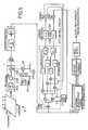
- FIG. 5is a block diagram of a fourth receiver system in accordance with the invention, designated particularly for mitigation of multi-path effects;
- FIG. 6is a diagram illustrating the front end of the GPS receiver with a circuit for applying a phase taper
- FIG. 7is a block diagram of a fifth receiver system in accordance with the invention for selecting circularly or elliptically polarised signals.
- multiple antenna GPS receiver apparatushas a multiple antenna array 10 comprising a number of antennas in a spaced-apart arrangement.
- the arrayis coupled to a receiving unit 12 , each antenna feeding signals to a respective input stage 14 of the receiver unit 12 .
- Each input stage 14has filtering and amplifier elements 14 A, 14 B, a down-convertor 14 C and an analogue-to-digital converter (ADC) 14 D.
- ADCanalogue-to-digital converter
- One of the antennasis selected as a reference source, the corresponding output 16 being coupled to a number of reference channels 18 , each of which is arranged to process the signals from a respective visible member of the GPS satellite constellation.
- each reference channelis shown, but it will be appreciated that different numbers of reference channels may be established according to the number of satellite transmitter signals to be processed.
- the signals from the other antennas, after amplification, down-conversion and digitisation in the respective input stages 14 ,are fed to measurement channels 20 , at least one for each received satellite signal at each antenna other than the reference antenna, so that each measurement channel processes a signal representative of the input signal from one satellite as received at one respective antenna.
- the outputs from the measurement channelsare representative of the carrier phase of each transmitter at each antenna.
- each reference channelcode and carrier tracking loops are established for each visible member of the satellite constellation.
- the code and carrier loopsinclude code and carrier replica generators which are used in a product or correlation detection arrangement.
- the reference channelhas a correlator stage 24 with four correlators each having input mixers, and an integrator.
- a first pair of correlators 26operates on an on-time version of the code replica and in-phase and quadrature versions of the carrier replica.
- the other pair 28 of correlatorsoperates on a composite version of the code replica formed from the early and late components of the code, each member of the pair operating on versions of the carrier replica which are in phase and quadrature.
- the code replicais formed in a conventional manner by feeding the outputs of the integrators in the second pair 28 of correlators to a delay locked loop 30 and thence to a delay locked loop filter 32 which controls a numerically controlled oscillator 34 .
- Thisacts as a clock for a pseudo random bit sequence code generator 36 for generating on-time (OT) and early-minus-late (E ⁇ L) versions of the code for the satellite signal being received via input 18 A.
- OT and E ⁇ L versions of the codeare fed to input mixers 38 , 40 for the carrier loop and code loop respectively.
- the first correlator pair 26feeds a phase detector 42 producing a signal representative of carrier phase which is then filtered by a carrier loop filter 44 for controlling a second numerically controlled oscillator 46 .
- This NCO 46is arranged to produce quadrature outputs as a carrier replica for feeding two further mixers 50 in the correlator pairs 26 , 28 , as shown.
- the tracking loopssettle with code phase and carrier phase estimates appropriate to the selected satellite and antenna combination.
- the reference channelmay have six rather than four correlators, one operating on an early version of the code replica and the other on a late version.
- the individual antenna elements of the array 10are normally close together, as measured on the scale of a GPS code phase wavelength (300 m). However, carrier phases for outputs from other antennas, but for the same satellite, are different since the antenna element spacing is on the same scale as the carrier wavelength (19 cm for L 1 in GPS).
- the measurement channels 20 for these antenna-satellite combinationsare established to receive the code and carrier replicas generated in the reference channel 24 . Accordingly, referring to FIG. 2, only the on-time (OT) code version from the coder 36 is applied to the measurement channel 20 , together with the quadrature and in-phase carrier replica versions.
- Each measurement channel 20has a correlator pair 52 with integrators which feed a carrier phase detector 54 producing a signal representing the phase of the particular antenna-satellite combination for that channel (at output 20 A).
- the measurement channels corresponding to the same satelliteoperate at least approximately at the peak value of the code correlation function.
- the carrier phase measurementsare different to the extent of the resolved line-of-sight differences between the reference antenna and the other antennas of the array 10 .
- the outputs 20 A(see FIG. 1) from the in phase and quadrature correlator channels are connected to feed tan ⁇ 1 representations to a combiner 58 the output of which is a spatially filtered representation of the signal from the corresponding satellite.
- the combiner 58in its simplest form, forms the sum of the input antenna measurements after they have been multiplied by amplitude and phase taper functions.
- the choice of the phase and amplitude multiplication coefficientsdetermines the spatial filtering characteristic.
- a least-mean-square (LMS) algorithmfor example, may be used to maximise the signal-to-noise ratio at the combiner output 58 A. If an adaptive equaliser is used to determine the phase and amplitude tapers, the early stages of adaptive processing are likely to be characterised by noise reduction subject to certain directional gain constraints rather than signal enhancements.
- the antenna array processing and the related spatial gain patterncan be different for each satellite in the GPS satellite constellation.
- This systemhas two antennas 101 , 102 which are coupled to two front end receiver circuits 103 , 104 .
- the front end receiver circuitsare not completely independent in that, in one preferred embodiment, they share common local oscillator signals derived from a fixed frequency synthesizer circuit 105 .
- the synthesizer circuit 105is coupled to a reference oscillator 106 of fixed frequency. Down-conversion of the received satellite signals takes place in each of the receiver circuits to an intermediate frequency (i.f.) at which the signals are sampled in time and digitized in ADCs 107 , 108 .
- the outputs of the ADCsare coupled to further down-converters 109 to 112 which are connected to variable frequency sources 113 and 114 .
- Each ADCtherefore yeilds two output signals which have been sampled in time so that the resulting i.f. samples are substantially separated by 90 degrees in phase, the signals 113 , 114 having identical frequencies but differing in phase by substantially 90 degrees.
- the signals 113 , 114are formed in a signal generator 115 which has a control input 116 .
- the outputs of the four further down-converters 109 - 112are combined in sideband canceller circuits 117 , 118 to substantially remove the unwanted sideband formed in the outputs from down-converters 109 - 112 .
- the output of the second down-conversion stepis at base-band.
- the outputs of the sideband cancellers 119 - 122are representations of the in-phase and quadrature base-band equivalents of the two received satellite signals.
- the outputs of the sideband canceller circuitsare coupled to code a plurality of de-spreading circuits 123 .
- the de-spreading circuitsare coupled to a source 124 of code replica signals representative of the signals emitted from the satellites.
- a multiplicity of versions of the replica signalsare generated with the feature, in this GPS embodiment, of having different delays in the range to the satellite.
- Pairs of replica signalsare coupled to integrator units 125 , which, along with the replica signal generator 124 , form a circuit whose output signals are representations of the cross-correlation of the received signal with the signal replicas. This circuit, therefore, substantially performs the function of a matched filter which is matched to the satellite transmitted signal.
- the outputs of the two integrator units 125are combined in each channel in respective first combiners 126 to produce a control signal component for a particular respective antenna-satellite combination.
- the signal replica generatoris approximately aligned with similar signals arriving from the satellite.
- the multiplicity of signalsis used initially to make approximate estimates of the range to one of the satellite signal sources.
- the outputs of each integrator pairresponds each of the replica signals to make different representations of the cross-correlation co-efficient.
- these signalsform a control signal to adjust the signal replica generator so that a chosen signal replica is aligned with the received satellite signal, or to form a control signal so that the phase of the carrier signal replica generator 115 can be brought into phase alignment with the received signal.
- a combining circuit 127which is coupled to a control system 128 which is, in turn, coupled to the signal replica generator 124 .
- the action of the control system 128is to maintain the alignment of the signal replica circuit 124 in the first instance.
- This second combiner 127is used to join the outputs of the two receivers and is also coupled to a control system 129 whose function is to maintain the phase of the carrier replica signal approximately the same as that from the two antennas.
- the circuits 126 , 127 combining the outputs from the channels coupled to the two antennasmay take several forms.
- the simplest embodimentis a circuit which forms the weighted sum of the two signals.
- the weighting functionmay be derived from the signal-to-noise ratio of each antenna channel or may be used to selectively couple just one of the channels to the input of the control system or systems.
- a simple solutionuses identical circuits to provide for the gain, filtering and down-conversion for all antenna circuits.
- the separate antenna circuitsare code-division-multiplexed prior to most of the radio frequency (r.f.) and intermediate frequency (i.f.) processing.
- r.f.radio frequency
- i.f.intermediate frequency
- only the front end filtering and low-noise amplifier units 150 A, 150 Bare individual to each antenna element 10 A.
- Stable gain or phase variations from channel to channelwould, in an adaptive system, be removed by adapting to a specific performance attribute.
- variations in group delay signatureswould not be removed by this form of adaptive processor. This is where the spread spectrum properties of code-division multiplexing shows a clear advantage over time division multiplexing (which degrades signal to noise ratio) and frequency division multiplexing (which renders imperfect group delay signatures).
- the front end antenna circuits 150contains a bandpass filter 150 A and a low-noise amplifier 150 B.
- these feed mixer stages 150 Cwhere, in each channel, the antenna signal is multiplied by a respective multiplier signal obtained from a PRBS (pseudo random bit sequence) code generator 153 .
- PRBSpseudo random bit sequence
- the code generator 153has an output K for each antenna circuit K, and each output from the generator 153 generates a different code signal, the product outputs from the mixers 150 C are each coded with a respective code which serves to identify the received signal when they are subsequently combined in adder 155 .
- the codes from the code generator 153are pseudo random spreading codes all having a common bit rate, and each is superimposed using mixers 157 (one for each antenna circuit), with a local oscillator signal from a local oscillator source 159 common to the plurality of antennas circuits. Accordingly, the mixers 150 C serve as down converters, converting the received signals to an intermediate frequency.
- the summed i.f. signal from the output of the adder 155is then fed through a common receiver channel consisting of an i.f. bandpass filter 161 and amplifier 163 , whereafter the i.f. signal is digitised in ADC 165 .
- ADC 165a common receiver channel consisting of an i.f. bandpass filter 161 and amplifier 163 , whereafter the i.f. signal is digitised in ADC 165 .
- the output of the ADC 165is fed to a plurality of channels 167 , one for each antenna, each containing a mixer 167 A which receives the same respective code as that applied in respect of the relevant antenna in mixers 150 C.
- Thishas the effect of isolating the representation of the respective received signal at the output of the mixer 167 A, this output representation then being split into plural sub-channels 169 corresponding to the satellites from which signals are received.
- inventionsmay use multiple antennas but with different processing algorithms. Spatial diversity processing allows systems to survive certain forms of interference. If the antenna elements are spaced moderately closely with inter-element distances of the order of several wavelengths, it is usually possible to provide some protection against propagation path fading. This is determined by the ambiguity function of the transmission channel which exhibit spatial, temporal and frequency coherence. Providing the antenna element spacing is greater than the spatial coherence distance, the antennas receive signal versions subject to statistically independent path configurations.
- a simple algorithm which can be used to gain some benefit from spatial diversitysimply selects the (antenna) channel exhibiting the largest output signal. Channels with deep amplitude fades are excluded from making a contribution to the signal.
- the optimum processing for randomly fading channels with a Rayleigh distributed amplitude probability density functionis well known.
- the processorrequires the summation of the weighted power from each channel.
- the optimum weightingis the ‘a priori’ signal to noise ratio. If, for instance, in a multi-path reception area, the channels support some portion of the direct path satellite signal, the amplitude distribution becomes Ricean (i.e. with one dominant component).
- the optimum processoris more complex in this case and, where possible, forms the coherent sum of the stable phase parts of the signal.
- Such a systemmay be applicable to the more complex GPS processors in situations where the propagation path from the satellite is subject to significant fading behavior. Inside buildings, GPS signal reception is dominated by multi-path propagation with significant fading.
- An adaptive processor as described aboveoffers the possibility of acceptable results in the variety of situations from direct signal path reception to multi-path dominated signal behaviour.
- This conceptis particularly applicable to mobile systems where the spatial and temporal signal fields have significant variation. It is more difficult to implement this in hand-held equipment due to the small physical size of the device in comparison with the coherence distance of the spatial signal field. Data relating to the signal ambiguity function in a variety of situations indicate that coherence distances of the order of 50 cm inside buildings may be expected. This is in accordance with the above-stated concept of signal interference on the scale of the GPS carrier wavelength. It will be appreciated, therefore, that implementation of spatial diversity is more applicable to vehicular applications due to the wider potential spacing of the antenna elements. The requirement for multiple antennas and the consequent need for coaxial cable connections within the vehicle is mitigated by printing the antennas on the rear screen and by locating at least a portion of the receiver unit in close proximity to the antenna output terminals.
- Multi-element antenna systemshave been described hereinbefore as a means to reduce multi-path signal propagation effects in ranging systems. It should be understood that this technique is useful in, at least, survey and timing applications of GPS as well as position-fixing.
- an antenna arrangementcomprises a two dimensional array 10 of n 2 elements coupled through individual low-noise amplifiers (LNA's) to first down-converters.
- LNA'slow-noise amplifiers
- Each down-converter 212 Bis driven by a common local oscillator 213 modulated with a distinct code chosen from a set of circularly non-correlated pseudo-random sequences, the code signals being derived, as in the embodiment of FIG. 4, from a multiple output code generator 215 and combined by respective mixers 217 with the local oscillator signal.
- Gold codesare well known examples of such sequences exhibiting bounded out-of-phase auto-correlation and cross-correlation properties. Gold codes with sequence lengths greater than 1023 are known and have the benefit of reducing the signal leakage between different sequences (or virtual antenna channels).
- FIG. 5is self-explanatory in the light of the following description and the above description of the other embodiments of the invention.
- the dimensions of the antenna array 10are small compared with the code wavelength of 300 m but large compared with the carrier wavelength.
- the inter-element spacingmay take a range of values, but there is much to support the application of the Nyquist sampling theorem applied spatially. This requires that samples of the signal field must be taken with inter-element spacing of less than ⁇ /2.
- the physical extent of the arrayis one of the design choices within the scope of the present invention and is related to the coherence distance of the GPS signal field derived from the scattering function.
- the antenna structurewill be ineffective in reducing multi-path propagation effects if the array size is smaller than the coherence distance—longer arrays have smaller beam-widths (or circles of confusion if expressed optically).
- Either a reference channel(processing signals from a selected antenna, as described above with reference to FIGS. 1 and 2 ), or a combination of channels, is used to generate a code-tracking signal using an early-late code replica.
- One such reference channelis provided for each satellite to be tracked.
- the code modulationis removed from the antenna processing channels by multiplication with an on-time code replica.
- One method for processing the output of an antenna arrayuses a Fourier Transform to convert the spatial samples into angular samples. Each such angular sample simply represents a beam pointing in one of directions defined by the transform.
- the beamshave the characteristic of a linear summation of the antenna element outputs pre-multiplied by a linear phase taper.
- the beam patternsare mutually orthogonal as in classic Fourier Transform theory.
- the Fourier Transform processorsuch as the generalised two-dimensional Karhunen-Loeve Transform.
- each satellite processormay be viewed as a spatial filtering operation, in which, for non-adaptive processors, the signal beam containing the least disturbance from multi-path propagation is selected for code measurements and carrier tracking.
- the antenna element pre-multiplier(a linear phase taper for the example described above) is replaced with an amplitude and phase weighting function prior to antenna signal combination.
- the simplest from of combineris used (a summation device), however, other forms are possible.
- One combinerdivides the antenna into two sub-arrays whose elements are summed. The output of the combiner is formed as the product of the two sub-array outputs.
- the spatial auto-correlation function for the array outputis ⁇ ( ⁇ ):
- ⁇ ( ⁇ )U*( ⁇ , ⁇ ).U( ⁇ , ⁇ ).( ⁇ , ⁇ )
- this lower multi-path propagation disturbanceif the peak in U( ⁇ , ⁇ ) selects substantially the direct path signal from the satellite. This is represented in ( ⁇ , ⁇ ) as a peak in ( ⁇ , ⁇ ) corresponding the satellite transmitter (SV) direction whereas multi-path propagation effects form a ‘halo’ effect (statistically) around the peak.
- a GPS receiving systemhas a GPS crossed dipole arrangement 10 with each dipole connected to a respective input channel 250 in an arrangement analageous to that shown in FIG. 4 .
- the two antenna signalsare coupled through a common rf and if processing assembly, as in the FIG. 4 embodiment, which provides phase and group delay stable amplification, filtering and down-conversion.
- One way to provide for such processingis by means of code division multiplexing for two channels through a common hardware r.f. processor. Each channel is attached to a separate antenna element.
- code division multiplex signalsare separated into two channels again. Code and carrier tracking channels are formed for each decoded antenna channel.
- the code loop tracking positionsare the same for each antenna.
- the carrier tracking loopsproduce phase and frequency estimates for the implicit GPS carrier signal.
- Performance benefitmay be taken by forming a single code tracking loop which is driven from a code phase error signal derived from both channels.
- the carrier signal tracking loopsshare a common frequency but have different phases depending upon the direction and type of received signal.
- both right and left hand circularly polarized receptorsmay be formed. This is representative of the behavior of a network located at the antennas which forms the sum and difference of the two received signals as shown in FIG. 7 .
- the performance attributes, which accrue from the digital implementation,are several fold.
Landscapes
- Engineering & Computer Science (AREA)
- Radar, Positioning & Navigation (AREA)
- Remote Sensing (AREA)
- Computer Networks & Wireless Communication (AREA)
- Physics & Mathematics (AREA)
- General Physics & Mathematics (AREA)
- Signal Processing (AREA)
- Position Fixing By Use Of Radio Waves (AREA)
Abstract
Description
Claims (76)
Applications Claiming Priority (3)
| Application Number | Priority Date | Filing Date | Title |
|---|---|---|---|
| GB0023072 | 2000-09-20 | ||
| GB0023072.2 | 2000-09-20 | ||
| GB0023072AGB2367199B (en) | 2000-09-20 | 2000-09-20 | Apparatus for receiving ranging signals |
Publications (2)
| Publication Number | Publication Date |
|---|---|
| US20020033766A1 US20020033766A1 (en) | 2002-03-21 |
| US6664921B2true US6664921B2 (en) | 2003-12-16 |
Family
ID=9899817
Family Applications (1)
| Application Number | Title | Priority Date | Filing Date |
|---|---|---|---|
| US09/731,167Expired - LifetimeUS6664921B2 (en) | 2000-09-20 | 2000-12-06 | Apparatus for receiving ranging signals |
Country Status (4)
| Country | Link |
|---|---|
| US (1) | US6664921B2 (en) |
| AU (1) | AU2001290069A1 (en) |
| GB (1) | GB2367199B (en) |
| WO (1) | WO2002025304A1 (en) |
Cited By (21)
| Publication number | Priority date | Publication date | Assignee | Title |
|---|---|---|---|---|
| US20030060178A1 (en)* | 2001-09-25 | 2003-03-27 | Ghassemzadeh Saeed S. | Multi-antenna/multi-receiver array diversity system |
| US20030112878A1 (en)* | 2001-12-14 | 2003-06-19 | David Kloper | Inroute training in a two-way satellite system |
| US20040248533A1 (en)* | 2003-05-23 | 2004-12-09 | Nokia Corporation | Adjustment of a phase difference between two signals |
| US20050094714A1 (en)* | 2003-10-31 | 2005-05-05 | Ian Robinson | Multi-carrier transceiver assembly |
| US20060034354A1 (en)* | 2004-08-16 | 2006-02-16 | Camp William O Jr | Apparatus, methods and computer program products for positioning system signal processing using parallel computational techniques |
| US20060033658A1 (en)* | 2004-08-16 | 2006-02-16 | Camp William O Jr | Apparatus, methods and computer program products for GPS signal acquisition using an adaptive search engine |
| US20060161049A1 (en)* | 1997-04-30 | 2006-07-20 | Richard Beane | Surgical access port |
| US20070058736A1 (en)* | 2005-09-12 | 2007-03-15 | Nguyen Hung C | Ultra wideband baseband chip with intelligent array radio and method of use thereof |
| US7292202B1 (en) | 2005-11-02 | 2007-11-06 | The United States Of America As Represented By The National Security Agency | Range limited antenna |
| US7453956B2 (en) | 2004-08-16 | 2008-11-18 | Sony Ericsson Mobile Communications Ab | Apparatus, methods and computer program products for signal acquisition using common demodulation templates |
| US20090036074A1 (en)* | 2007-08-01 | 2009-02-05 | Delphi Delco Electronics Europe Gmbh | Antenna diversity system having two antennas for radio reception in vehicles |
| US7642986B1 (en) | 2005-11-02 | 2010-01-05 | The United States Of America As Represented By The Director, National Security Agency | Range limited antenna |
| US20110188618A1 (en)* | 2010-02-02 | 2011-08-04 | Feller Walter J | Rf/digital signal-separating gnss receiver and manufacturing method |
| US20110211508A1 (en)* | 2002-08-28 | 2011-09-01 | Pieter Van Rooyen | Iterative multi-stage detection technique for a diversity receiver having multiple antenna elements |
| US20110316739A1 (en)* | 2007-05-21 | 2011-12-29 | Donald Chin-Dong Chang | Digital beam-forming apparatus and technique for a multi-beam global positioning system (gps) receiver |
| US20120299773A1 (en)* | 2011-05-23 | 2012-11-29 | Sony Coropration | Beam forming device and method |
| US20140045439A1 (en)* | 2008-08-29 | 2014-02-13 | Empire Technology Development, Llc. | Weighting factor adjustment in adaptive antenna arrays |
| US8669900B2 (en) | 2010-11-17 | 2014-03-11 | Trimble Navigation Limited | Global navigation satellite antenna systems and methods |
| US9435893B2 (en) | 2007-05-21 | 2016-09-06 | Spatial Digital Systems, Inc. | Digital beam-forming apparatus and technique for a multi-beam global positioning system (GPS) receiver |
| US10446926B2 (en)* | 2013-10-28 | 2019-10-15 | Huawei Technologies Co., Ltd. | Base station antenna |
| EP4498128A3 (en)* | 2023-07-06 | 2025-05-21 | Fuba Automotive Electronics GmbH | Satellite navigation receiving system |
Families Citing this family (33)
| Publication number | Priority date | Publication date | Assignee | Title |
|---|---|---|---|---|
| CN100385826C (en)* | 2002-06-24 | 2008-04-30 | 美国博通公司 | Reduced complexity antenna system with multiplexed receive chain processing |
| US8457230B2 (en) | 2002-08-21 | 2013-06-04 | Broadcom Corporation | Reconfigurable orthogonal frequency division multiplexing (OFDM) chip supporting single weight diversity |
| EP1540763B1 (en)* | 2002-08-21 | 2007-04-18 | Zyray Wireless, Inc. | Antenna array including virtual antenna elements and method |
| EP1404033B1 (en)* | 2002-09-30 | 2018-02-14 | MITAC International Corporation | Adaptative antenna array receiver and processor |
| DE10317549A1 (en)* | 2003-04-15 | 2004-11-04 | Daimlerchrysler Ag | Radio transmission method and radio transmission system |
| US20060227898A1 (en)* | 2003-07-10 | 2006-10-12 | Gibson Timothy P | Radio receiver |
| US7437135B2 (en)* | 2003-10-30 | 2008-10-14 | Interdigital Technology Corporation | Joint channel equalizer interference canceller advanced receiver |
| US7400692B2 (en)* | 2004-01-14 | 2008-07-15 | Interdigital Technology Corporation | Telescoping window based equalization |
| DE102004027666B4 (en)* | 2004-06-07 | 2006-07-27 | Infineon Technologies Ag | Improving the reliability and accuracy of position determination methods by estimating the Rice factor of a radio link |
| US8350754B2 (en)* | 2004-09-30 | 2013-01-08 | Ming-Chiang Li | Robust and broadband signal processing using replica generation apparatus |
| KR100842087B1 (en)* | 2006-12-28 | 2008-06-30 | 삼성전자주식회사 | Array antenna system |
| US8081933B2 (en) | 2007-07-13 | 2011-12-20 | Honeywell International Inc. | Reconfigurable aircraft radio communications system |
| US8019338B2 (en) | 2008-05-29 | 2011-09-13 | Honeywell International Inc. | Reconfigurable aircraft communications system with integrated avionics communication router and audio management functions |
| GB2474923B (en)* | 2008-07-18 | 2011-11-16 | Phasor Solutions Ltd | A phased array antenna and a method of operating a phased array antenna |
| US8130145B2 (en) | 2009-06-24 | 2012-03-06 | Qualcomm Incorporated | Receive diversity in GNSS receivers |
| WO2011137265A1 (en) | 2010-04-28 | 2011-11-03 | Maxlinear, Inc. | Gps antenna diversity and noise mitigation |
| US8711993B2 (en) | 2010-12-10 | 2014-04-29 | Honeywell International Inc. | Wideband multi-channel receiver with fixed-frequency notch filter for interference rejection |
| US8494472B1 (en)* | 2011-03-28 | 2013-07-23 | AMI Research & Development, LLC | Reconfigurable chirp fourier transform based continuous convolution processor |
| JP2013192172A (en)* | 2012-03-15 | 2013-09-26 | Omron Corp | Rfid tag system and rfid reader/writer |
| FR2988483B1 (en)* | 2012-03-22 | 2014-03-07 | Thales Sa | DEVICE FOR RECEIVING MULTI-ANTENNA RADIO NAVIGATION SIGNALS |
| FR2988484B1 (en) | 2012-03-22 | 2014-03-07 | Thales Sa | DEVICE FOR RECEIVING MULTI-ANTENNA RADIO NAVIGATION SIGNALS AND COMMON SYNCHRONIZATION SERVICING |
| US9086477B2 (en) | 2012-06-06 | 2015-07-21 | Novatel Inc. | Anti-jamming subsystem employing an antenna array with a horizontal circular reception pattern |
| US20140125520A1 (en)* | 2012-06-22 | 2014-05-08 | Patrick C. Fenton | Anti-jamming subsystem employing an antenna with a horizontal reception pattern |
| CN103472467B (en)* | 2013-09-17 | 2015-06-24 | 豪芯微电子科技(上海)有限公司 | Array type channel, GNSS receiver and signal processing method |
| US10690777B2 (en)* | 2014-07-31 | 2020-06-23 | Fraunhofer-Gesellschaft Zur Foerderung Der Angewandten Forschung E.V. | Multi-antenna-GNSS receiver-system to raise the probability of line of sight |
| EP3215864B1 (en)* | 2014-11-07 | 2020-07-29 | Sony Corporation | Determining the geographic location of a portable electronic device with a synthetic antenna array |
| US9647867B2 (en)* | 2015-06-19 | 2017-05-09 | Texas Instruments Incorporated | Wideband IQ mismatch correction for direct down-conversion receiver |
| DE102017207575A1 (en)* | 2017-05-05 | 2018-11-08 | Continental Teves Ag & Co. Ohg | Radio receiver for positioning systems |
| JP6743761B2 (en)* | 2017-05-29 | 2020-08-19 | 株式会社デンソー | Ranging sensor |
| WO2018224488A1 (en) | 2017-06-06 | 2018-12-13 | Fraunhofer-Gesellschaft zur Förderung der angewandten Forschung e.V. | Radio frequency communication and jamming device and method for physically secured friendly radio frequency communication and for jamming hostile radio frequency communication |
| WO2020086906A1 (en) | 2018-10-24 | 2020-04-30 | Red Leader Technologies, Inc. | Lidar system and method of operation |
| KR20230074273A (en)* | 2020-10-13 | 2023-05-26 | 레드 리더 테크놀로지스, 인크. | lidar system and operation method |
| CN112224446B (en)* | 2020-10-16 | 2022-06-21 | 中国直升机设计研究所 | High-speed coaxial dual-rotor blade tip distance measuring method based on phase distance measuring principle |
Citations (27)
| Publication number | Priority date | Publication date | Assignee | Title |
|---|---|---|---|---|
| US3952304A (en)* | 1973-11-23 | 1976-04-20 | Hughes Aircraft Company | Tracking system utilizing Kalman filter concepts |
| US4179696A (en)* | 1977-05-24 | 1979-12-18 | Westinghouse Electric Corp. | Kalman estimator tracking system |
| EP0455943A2 (en) | 1990-05-10 | 1991-11-13 | Pioneer Electronic Corporation | Apparatus and method for positioning of a GPS receiver |
| US5101356A (en) | 1989-11-21 | 1992-03-31 | Unisys Corporation | Moving vehicle attitude measuring system |
| US5268695A (en) | 1992-10-06 | 1993-12-07 | Trimble Navigation Limited | Differential phase measurement through antenna multiplexing |
| DE4223676A1 (en) | 1992-07-17 | 1994-01-20 | Siemens Ag | Adaptive spatial filtering or noise suppression in radio reception - provides class of possible linear planar or spatial group geometries of groups of antennae |
| US5317323A (en) | 1993-03-05 | 1994-05-31 | E-Systems, Inc. | Passive high accuracy geolocation system and method |
| US5343212A (en)* | 1992-12-11 | 1994-08-30 | Litton Industries, Inc. | (AOA/LBI) emitter ranging method and apparatus |
| US5347536A (en) | 1993-03-17 | 1994-09-13 | The United States Of America As Represented By The Administrator Of The National Aeronautics And Space Administration | Multipath noise reduction for spread spectrum signals |
| WO1995022209A1 (en) | 1994-02-10 | 1995-08-17 | International Business Machines Corporation | Method and apparatus for multiuser-interference reduction |
| US5457466A (en)* | 1993-09-07 | 1995-10-10 | Litton Systems Inc. | Emitter azimuth and elevation direction finding using only linear interferometer arrays |
| US5543803A (en) | 1994-08-23 | 1996-08-06 | Honeywell Inc. | Fail safe receiver system |
| EP0763749A1 (en) | 1995-08-07 | 1997-03-19 | Litton Systems, Inc. | Integrated gps/inertial navigation apparatus providing improved heading estimates |
| EP0806679A1 (en) | 1996-05-09 | 1997-11-12 | Agence Spatiale Europeenne | Receiving device for a navigation system, especially for satellite |
| WO1998007044A1 (en) | 1996-08-09 | 1998-02-19 | Megapulse Inc. | Vehicular tracking and location |
| WO1998029755A1 (en) | 1996-12-31 | 1998-07-09 | Honeywell Inc. | Gps multipath detection method and system |
| US5805583A (en) | 1995-08-25 | 1998-09-08 | Terayon Communication Systems | Process for communicating multiple channels of digital data in distributed systems using synchronous code division multiple access |
| US5917446A (en) | 1995-11-08 | 1999-06-29 | The Charles Stark Draper Laboratory, Inc. | Radio-wave reception system using inertial data in the receiver beamforming operation |
| US5917448A (en) | 1997-08-07 | 1999-06-29 | Rockwell Science Center, Inc. | Attitude determination system with sequencing antenna inputs |
| US5926135A (en) | 1998-01-08 | 1999-07-20 | Lucent Technologies | Steerable nulling of wideband interference signals |
| US5952968A (en) | 1997-09-15 | 1999-09-14 | Rockwell International Corporation | Method and apparatus for reducing jamming by beam forming using navigational data |
| WO1999059266A1 (en) | 1998-05-12 | 1999-11-18 | Motorola Inc. | Method and apparatus for short spreading in a code division multiple access communication system |
| US5990827A (en) | 1997-03-28 | 1999-11-23 | Vectorlink, Inc. | Structure of a position processing apparatus |
| US5990831A (en) | 1998-08-25 | 1999-11-23 | Rockwell International Corporation | FFT implementation of digital antenna arry processing in GNSS receivers |
| US6111895A (en) | 1997-05-14 | 2000-08-29 | At&T Corp. | Wideband transmission through wire |
| US6114988A (en) | 1996-12-31 | 2000-09-05 | Honeywell Inc. | GPS receiver fault detection method and system |
| US6259404B1 (en)* | 1995-12-15 | 2001-07-10 | Signatron Technology Corporation | Position location system and method |
- 2000
- 2000-09-20GBGB0023072Apatent/GB2367199B/ennot_activeExpired - Fee Related
- 2000-12-06USUS09/731,167patent/US6664921B2/ennot_activeExpired - Lifetime
- 2001
- 2001-09-20WOPCT/GB2001/004212patent/WO2002025304A1/enactiveApplication Filing
- 2001-09-20AUAU2001290069Apatent/AU2001290069A1/ennot_activeAbandoned
Patent Citations (28)
| Publication number | Priority date | Publication date | Assignee | Title |
|---|---|---|---|---|
| US3952304A (en)* | 1973-11-23 | 1976-04-20 | Hughes Aircraft Company | Tracking system utilizing Kalman filter concepts |
| US4179696A (en)* | 1977-05-24 | 1979-12-18 | Westinghouse Electric Corp. | Kalman estimator tracking system |
| US5101356A (en) | 1989-11-21 | 1992-03-31 | Unisys Corporation | Moving vehicle attitude measuring system |
| EP0455943A2 (en) | 1990-05-10 | 1991-11-13 | Pioneer Electronic Corporation | Apparatus and method for positioning of a GPS receiver |
| DE4223676A1 (en) | 1992-07-17 | 1994-01-20 | Siemens Ag | Adaptive spatial filtering or noise suppression in radio reception - provides class of possible linear planar or spatial group geometries of groups of antennae |
| US5268695A (en) | 1992-10-06 | 1993-12-07 | Trimble Navigation Limited | Differential phase measurement through antenna multiplexing |
| US5343212A (en)* | 1992-12-11 | 1994-08-30 | Litton Industries, Inc. | (AOA/LBI) emitter ranging method and apparatus |
| US5317323A (en) | 1993-03-05 | 1994-05-31 | E-Systems, Inc. | Passive high accuracy geolocation system and method |
| US5347536A (en) | 1993-03-17 | 1994-09-13 | The United States Of America As Represented By The Administrator Of The National Aeronautics And Space Administration | Multipath noise reduction for spread spectrum signals |
| US5457466A (en)* | 1993-09-07 | 1995-10-10 | Litton Systems Inc. | Emitter azimuth and elevation direction finding using only linear interferometer arrays |
| WO1995022209A1 (en) | 1994-02-10 | 1995-08-17 | International Business Machines Corporation | Method and apparatus for multiuser-interference reduction |
| US5543803A (en) | 1994-08-23 | 1996-08-06 | Honeywell Inc. | Fail safe receiver system |
| EP0763749A1 (en) | 1995-08-07 | 1997-03-19 | Litton Systems, Inc. | Integrated gps/inertial navigation apparatus providing improved heading estimates |
| US5805583A (en) | 1995-08-25 | 1998-09-08 | Terayon Communication Systems | Process for communicating multiple channels of digital data in distributed systems using synchronous code division multiple access |
| US5917446A (en) | 1995-11-08 | 1999-06-29 | The Charles Stark Draper Laboratory, Inc. | Radio-wave reception system using inertial data in the receiver beamforming operation |
| US6259404B1 (en)* | 1995-12-15 | 2001-07-10 | Signatron Technology Corporation | Position location system and method |
| EP0806679A1 (en) | 1996-05-09 | 1997-11-12 | Agence Spatiale Europeenne | Receiving device for a navigation system, especially for satellite |
| US6069583A (en) | 1996-05-09 | 2000-05-30 | Agence Spatiale Europeene | Receiver for a navigation system, in particular a satellite navigation system |
| WO1998007044A1 (en) | 1996-08-09 | 1998-02-19 | Megapulse Inc. | Vehicular tracking and location |
| US6114988A (en) | 1996-12-31 | 2000-09-05 | Honeywell Inc. | GPS receiver fault detection method and system |
| WO1998029755A1 (en) | 1996-12-31 | 1998-07-09 | Honeywell Inc. | Gps multipath detection method and system |
| US5990827A (en) | 1997-03-28 | 1999-11-23 | Vectorlink, Inc. | Structure of a position processing apparatus |
| US6111895A (en) | 1997-05-14 | 2000-08-29 | At&T Corp. | Wideband transmission through wire |
| US5917448A (en) | 1997-08-07 | 1999-06-29 | Rockwell Science Center, Inc. | Attitude determination system with sequencing antenna inputs |
| US5952968A (en) | 1997-09-15 | 1999-09-14 | Rockwell International Corporation | Method and apparatus for reducing jamming by beam forming using navigational data |
| US5926135A (en) | 1998-01-08 | 1999-07-20 | Lucent Technologies | Steerable nulling of wideband interference signals |
| WO1999059266A1 (en) | 1998-05-12 | 1999-11-18 | Motorola Inc. | Method and apparatus for short spreading in a code division multiple access communication system |
| US5990831A (en) | 1998-08-25 | 1999-11-23 | Rockwell International Corporation | FFT implementation of digital antenna arry processing in GNSS receivers |
Cited By (37)
| Publication number | Priority date | Publication date | Assignee | Title |
|---|---|---|---|---|
| US20060161049A1 (en)* | 1997-04-30 | 2006-07-20 | Richard Beane | Surgical access port |
| US8509723B2 (en) | 2001-09-25 | 2013-08-13 | At&T Intellectual Property Ii, Lp | Multi-antenna/multi-receiver array diversity system |
| US20030060178A1 (en)* | 2001-09-25 | 2003-03-27 | Ghassemzadeh Saeed S. | Multi-antenna/multi-receiver array diversity system |
| US7155192B2 (en)* | 2001-09-25 | 2006-12-26 | At&T Corp. | Multi-antenna/multi-receiver array diversity system |
| US8818316B2 (en) | 2001-09-25 | 2014-08-26 | At&T Intellectual Property Ii, L.P. | Multi-antenna/multi-receiver array diversity system |
| US20090075618A1 (en)* | 2001-09-25 | 2009-03-19 | Ghassemzadeh Saeed S | Multi-antenna/multi-receiver array diversity system |
| US20030112878A1 (en)* | 2001-12-14 | 2003-06-19 | David Kloper | Inroute training in a two-way satellite system |
| US7656813B2 (en)* | 2001-12-14 | 2010-02-02 | Hughes Network Systems, Inc. | Inroute training in a two-way satellite system |
| US20110217942A1 (en)* | 2002-08-28 | 2011-09-08 | Pieter Van Rooyen | Iterative multi-stage detection technique for a diversity receiver having multiple antenna elements |
| US20110211508A1 (en)* | 2002-08-28 | 2011-09-01 | Pieter Van Rooyen | Iterative multi-stage detection technique for a diversity receiver having multiple antenna elements |
| US7194279B2 (en)* | 2003-05-23 | 2007-03-20 | Nokia Corporation | Adjustment of a phase difference between two signals |
| US20040248533A1 (en)* | 2003-05-23 | 2004-12-09 | Nokia Corporation | Adjustment of a phase difference between two signals |
| US7869528B2 (en)* | 2003-10-31 | 2011-01-11 | Northrop Grumman Systems Corporation | Multi-carrier transceiver assembly |
| US20050094714A1 (en)* | 2003-10-31 | 2005-05-05 | Ian Robinson | Multi-carrier transceiver assembly |
| US20060034354A1 (en)* | 2004-08-16 | 2006-02-16 | Camp William O Jr | Apparatus, methods and computer program products for positioning system signal processing using parallel computational techniques |
| US7453956B2 (en) | 2004-08-16 | 2008-11-18 | Sony Ericsson Mobile Communications Ab | Apparatus, methods and computer program products for signal acquisition using common demodulation templates |
| US7358897B2 (en) | 2004-08-16 | 2008-04-15 | Sony Ericsson Mobile Communicatios Ab | Apparatus, methods and computer program products for GPS signal acquisition using an adaptive search engine |
| US20060033658A1 (en)* | 2004-08-16 | 2006-02-16 | Camp William O Jr | Apparatus, methods and computer program products for GPS signal acquisition using an adaptive search engine |
| US7986736B2 (en)* | 2005-09-12 | 2011-07-26 | Sigma Designs, Inc. | Ultra wideband baseband chip with intelligent array radio and method of use thereof |
| US20070058736A1 (en)* | 2005-09-12 | 2007-03-15 | Nguyen Hung C | Ultra wideband baseband chip with intelligent array radio and method of use thereof |
| US7642986B1 (en) | 2005-11-02 | 2010-01-05 | The United States Of America As Represented By The Director, National Security Agency | Range limited antenna |
| US7292202B1 (en) | 2005-11-02 | 2007-11-06 | The United States Of America As Represented By The National Security Agency | Range limited antenna |
| US20110316739A1 (en)* | 2007-05-21 | 2011-12-29 | Donald Chin-Dong Chang | Digital beam-forming apparatus and technique for a multi-beam global positioning system (gps) receiver |
| US8232918B2 (en)* | 2007-05-21 | 2012-07-31 | Spatial Digital Systems, Inc. | Digital beam-forming apparatus and technique for a multi-beam global positioning system (GPS) receiver |
| US9435893B2 (en) | 2007-05-21 | 2016-09-06 | Spatial Digital Systems, Inc. | Digital beam-forming apparatus and technique for a multi-beam global positioning system (GPS) receiver |
| US20090036074A1 (en)* | 2007-08-01 | 2009-02-05 | Delphi Delco Electronics Europe Gmbh | Antenna diversity system having two antennas for radio reception in vehicles |
| US8270924B2 (en)* | 2007-08-01 | 2012-09-18 | Delphi Delco Electronics Europe Gmbh | Antenna diversity system having two antennas for radio reception in vehicles |
| US20140045439A1 (en)* | 2008-08-29 | 2014-02-13 | Empire Technology Development, Llc. | Weighting factor adjustment in adaptive antenna arrays |
| US8934843B2 (en)* | 2008-08-29 | 2015-01-13 | Empire Technology Development Llc | Weighting factor adjustment in adaptive antenna arrays |
| US20110188618A1 (en)* | 2010-02-02 | 2011-08-04 | Feller Walter J | Rf/digital signal-separating gnss receiver and manufacturing method |
| US8669900B2 (en) | 2010-11-17 | 2014-03-11 | Trimble Navigation Limited | Global navigation satellite antenna systems and methods |
| US9417328B2 (en) | 2010-11-17 | 2016-08-16 | Trimble Navigation Limited | Global navigation satellite antenna systems and methods |
| US9121943B2 (en)* | 2011-05-23 | 2015-09-01 | Sony Corporation | Beam forming device and method |
| US20120299773A1 (en)* | 2011-05-23 | 2012-11-29 | Sony Coropration | Beam forming device and method |
| US10446926B2 (en)* | 2013-10-28 | 2019-10-15 | Huawei Technologies Co., Ltd. | Base station antenna |
| US11563268B2 (en) | 2013-10-28 | 2023-01-24 | Huawei Technologies Co., Ltd. | Base station antenna |
| EP4498128A3 (en)* | 2023-07-06 | 2025-05-21 | Fuba Automotive Electronics GmbH | Satellite navigation receiving system |
Also Published As
| Publication number | Publication date |
|---|---|
| AU2001290069A1 (en) | 2002-04-02 |
| US20020033766A1 (en) | 2002-03-21 |
| WO2002025304A1 (en) | 2002-03-28 |
| GB2367199B (en) | 2005-01-26 |
| GB2367199A (en) | 2002-03-27 |
| GB0023072D0 (en) | 2000-11-01 |
Similar Documents
| Publication | Publication Date | Title |
|---|---|---|
| US6664921B2 (en) | Apparatus for receiving ranging signals | |
| US6784831B1 (en) | Method and apparatus for GPS signal receiving that employs a frequency-division-multiplexed phased array communication mechanism | |
| US6788734B2 (en) | Rake receiver for spread spectrum signal demodulation | |
| US6680699B2 (en) | Signal reception method and device | |
| Cuntz et al. | Concepts, development, and validation of multiantenna GNSS receivers for resilient navigation | |
| US5694416A (en) | Direct sequence spread spectrum receiver and antenna array for the simultaneous formation of a beam on a signal source and a null on an interfering jammer | |
| US5966403A (en) | Code multipath error estimation using weighted correlations | |
| Sun et al. | A self-coherence anti-jamming GPS receiver | |
| US6166690A (en) | Adaptive nulling methods for GPS reception in multiple-interference environments | |
| US6828935B1 (en) | Digitally synthesized phased antenna for multibeam global positioning | |
| US4734701A (en) | Null processing receiver apparatus and method | |
| US6727846B1 (en) | Apparatus and method for minimizing multipath signal errors during tracking of GPS satellite signals | |
| US8417207B2 (en) | High-performance cellular telephone receiver | |
| Chiba et al. | Digital beam forming (DBF) antenna system for mobile communications | |
| US6947474B2 (en) | Rake receiver for spread spectrum signal demodulation | |
| US20050078739A1 (en) | Anti- jamming method for spread-spectrum radio signal receivers | |
| Ruegamer et al. | A Bavarian initiative towards a robust Galileo PRS receiver | |
| US20050088337A1 (en) | Vertically stacked turnstile array | |
| WO1998008319A9 (en) | Rake receiver for spread spectrum signal demodulation | |
| Dabak et al. | Interference suppression in a GPS receiver with 4 element array design and implementation of beamforming algorithms | |
| WO1998008319A1 (en) | Rake receiver for spread spectrum signal demodulation | |
| US6552684B2 (en) | Direction of arrival estimation method and radio reception apparatus | |
| Fernández-Prades et al. | Eigenbeamforming for interference mitigation in GNSS receivers | |
| Mañosas-Caballú et al. | Robust beamforming via FIR filtering for GNSS multipath mitigation | |
| JP2007327942A (en) | Radar signal processing apparatus and radar signal processing method |
Legal Events
| Date | Code | Title | Description |
|---|---|---|---|
| AS | Assignment | Owner name:PARTHUS (UK) LIMITED, UNITED KINGDOM Free format text:ASSIGNMENT OF ASSIGNORS INTEREST;ASSIGNOR:PRATT, ANTHONY RICHARD;REEL/FRAME:011355/0911 Effective date:20001027 | |
| STCF | Information on status: patent grant | Free format text:PATENTED CASE | |
| AS | Assignment | Owner name:CEVA IRELAND LIMITED, IRELAND Free format text:ASSIGNMENT OF ASSIGNORS INTEREST;ASSIGNOR:CEVA (UK) LIMITED;REEL/FRAME:015494/0093 Effective date:20040529 | |
| AS | Assignment | Owner name:GLONAV LIMITED, IRELAND Free format text:ASSIGNMENT OF ASSIGNORS INTEREST;ASSIGNOR:CEVA IRELAND LIMITED;REEL/FRAME:018688/0808 Effective date:20060707 | |
| FPAY | Fee payment | Year of fee payment:4 | |
| SULP | Surcharge for late payment | ||
| AS | Assignment | Owner name:ST WIRELESS SA,SWITZERLAND Free format text:ASSIGNMENT OF ASSIGNORS INTEREST;ASSIGNOR:GLONAV LIMITED;REEL/FRAME:024390/0119 Effective date:20080728 Owner name:ST ERICSSON SA,SWITZERLAND Free format text:CHANGE OF NAME;ASSIGNOR:ST WIRELESS SA;REEL/FRAME:024390/0128 Effective date:20091021 Owner name:ST WIRELESS SA, SWITZERLAND Free format text:ASSIGNMENT OF ASSIGNORS INTEREST;ASSIGNOR:GLONAV LIMITED;REEL/FRAME:024390/0119 Effective date:20080728 Owner name:ST ERICSSON SA, SWITZERLAND Free format text:CHANGE OF NAME;ASSIGNOR:ST WIRELESS SA;REEL/FRAME:024390/0128 Effective date:20091021 | |
| AS | Assignment | Owner name:ST WIRELESS SA, SWITZERLAND Free format text:CORRECTIVE ASSIGNMENT TO CORRECT THE STREET ADDRESS OF ASSIGNEE PREVIOUSLY RECORDED ON REEL 024390 FRAME 0119. ASSIGNOR(S) HEREBY CONFIRMS THE "...ASSIGNOR DOES HEREBY SELL, CONVEY, TRANSFER AND ASSIGN TO ASSIGNEE...";ASSIGNOR:GLONAV LIMITED;REEL/FRAME:024686/0483 Effective date:20080728 Owner name:ST-ERICSSON SA, SWITZERLAND Free format text:CORRECTIVE ASSIGNMENT TO CORRECT THE STREET ADDRESS OF ASSIGNOR, STREET ADDRESS OF ASSIGNEE AND SPELLING OF NAME OF ASSIGNEE (CHANGE OF NAME) PREVIOUSLY RECORDED ON REEL 024390 FRAME 0128. ASSIGNOR(S) HEREBY CONFIRMS THE NEW NAME TO BE "ST-ERICSSON SA";ASSIGNOR:ST WIRELESS SA;REEL/FRAME:024686/0626 Effective date:20091021 | |
| FEPP | Fee payment procedure | Free format text:PAT HOLDER NO LONGER CLAIMS SMALL ENTITY STATUS, ENTITY STATUS SET TO UNDISCOUNTED (ORIGINAL EVENT CODE: STOL); ENTITY STATUS OF PATENT OWNER: LARGE ENTITY | |
| FPAY | Fee payment | Year of fee payment:8 | |
| AS | Assignment | Owner name:INTEL CORPORATION, CALIFORNIA Free format text:ASSIGNMENT OF ASSIGNORS INTEREST;ASSIGNOR:ST-ERICSSON SA;REEL/FRAME:031270/0405 Effective date:20130718 | |
| FEPP | Fee payment procedure | Free format text:PAYOR NUMBER ASSIGNED (ORIGINAL EVENT CODE: ASPN); ENTITY STATUS OF PATENT OWNER: LARGE ENTITY | |
| AS | Assignment | Owner name:INTEL IP CORPORATION, CALIFORNIA Free format text:ASSIGNMENT OF ASSIGNORS INTEREST;ASSIGNOR:ST-ERICSSON SA;REEL/FRAME:031728/0485 Effective date:20130718 | |
| AS | Assignment | Owner name:INTEL CORPORATION, CALIFORNIA Free format text:CORRECTIVE ASSIGNMENT TO CORRECT THE ASSIGNEE NAME PREVIOUSLY RECORDED AT REEL: 031728 FRAME: 0485. ASSIGNOR(S) HEREBY CONFIRMS THE ASSIGNMENT;ASSIGNOR:ST-ERICSSON SA;REEL/FRAME:035307/0378 Effective date:20130718 | |
| FPAY | Fee payment | Year of fee payment:12 | |
| AS | Assignment | Owner name:INTEL CORPORATION, CALIFORNIA Free format text:CONFIRMATORY ASSIGNMENT;ASSIGNOR:INTEL IP CORPORATION;REEL/FRAME:053051/0295 Effective date:20200529 | |
| AS | Assignment | Owner name:APPLE INC., CALIFORNIA Free format text:ASSIGNMENT OF ASSIGNORS INTEREST;ASSIGNOR:INTEL CORPORATION;REEL/FRAME:053309/0140 Effective date:20191130 |