US6663665B2 - Single puncture bifurcation graft deployment system - Google Patents
Single puncture bifurcation graft deployment systemDownload PDFInfo
- Publication number
- US6663665B2 US6663665B2US09/795,993US79599301AUS6663665B2US 6663665 B2US6663665 B2US 6663665B2US 79599301 AUS79599301 AUS 79599301AUS 6663665 B2US6663665 B2US 6663665B2
- Authority
- US
- United States
- Prior art keywords
- branch
- graft
- vessel
- deployment system
- prosthesis
- Prior art date
- Legal status (The legal status is an assumption and is not a legal conclusion. Google has not performed a legal analysis and makes no representation as to the accuracy of the status listed.)
- Expired - Lifetime, expires
Links
Images


Classifications
- A—HUMAN NECESSITIES
- A61—MEDICAL OR VETERINARY SCIENCE; HYGIENE
- A61F—FILTERS IMPLANTABLE INTO BLOOD VESSELS; PROSTHESES; DEVICES PROVIDING PATENCY TO, OR PREVENTING COLLAPSING OF, TUBULAR STRUCTURES OF THE BODY, e.g. STENTS; ORTHOPAEDIC, NURSING OR CONTRACEPTIVE DEVICES; FOMENTATION; TREATMENT OR PROTECTION OF EYES OR EARS; BANDAGES, DRESSINGS OR ABSORBENT PADS; FIRST-AID KITS
- A61F2/00—Filters implantable into blood vessels; Prostheses, i.e. artificial substitutes or replacements for parts of the body; Appliances for connecting them with the body; Devices providing patency to, or preventing collapsing of, tubular structures of the body, e.g. stents
- A61F2/02—Prostheses implantable into the body
- A61F2/04—Hollow or tubular parts of organs, e.g. bladders, tracheae, bronchi or bile ducts
- A61F2/06—Blood vessels
- A61F2/07—Stent-grafts
- A—HUMAN NECESSITIES
- A61—MEDICAL OR VETERINARY SCIENCE; HYGIENE
- A61F—FILTERS IMPLANTABLE INTO BLOOD VESSELS; PROSTHESES; DEVICES PROVIDING PATENCY TO, OR PREVENTING COLLAPSING OF, TUBULAR STRUCTURES OF THE BODY, e.g. STENTS; ORTHOPAEDIC, NURSING OR CONTRACEPTIVE DEVICES; FOMENTATION; TREATMENT OR PROTECTION OF EYES OR EARS; BANDAGES, DRESSINGS OR ABSORBENT PADS; FIRST-AID KITS
- A61F2/00—Filters implantable into blood vessels; Prostheses, i.e. artificial substitutes or replacements for parts of the body; Appliances for connecting them with the body; Devices providing patency to, or preventing collapsing of, tubular structures of the body, e.g. stents
- A61F2/95—Instruments specially adapted for placement or removal of stents or stent-grafts
- A61F2/954—Instruments specially adapted for placement or removal of stents or stent-grafts for placing stents or stent-grafts in a bifurcation
- A—HUMAN NECESSITIES
- A61—MEDICAL OR VETERINARY SCIENCE; HYGIENE
- A61F—FILTERS IMPLANTABLE INTO BLOOD VESSELS; PROSTHESES; DEVICES PROVIDING PATENCY TO, OR PREVENTING COLLAPSING OF, TUBULAR STRUCTURES OF THE BODY, e.g. STENTS; ORTHOPAEDIC, NURSING OR CONTRACEPTIVE DEVICES; FOMENTATION; TREATMENT OR PROTECTION OF EYES OR EARS; BANDAGES, DRESSINGS OR ABSORBENT PADS; FIRST-AID KITS
- A61F2/00—Filters implantable into blood vessels; Prostheses, i.e. artificial substitutes or replacements for parts of the body; Appliances for connecting them with the body; Devices providing patency to, or preventing collapsing of, tubular structures of the body, e.g. stents
- A61F2/95—Instruments specially adapted for placement or removal of stents or stent-grafts
- A61F2/962—Instruments specially adapted for placement or removal of stents or stent-grafts having an outer sleeve
- A61F2/966—Instruments specially adapted for placement or removal of stents or stent-grafts having an outer sleeve with relative longitudinal movement between outer sleeve and prosthesis, e.g. using a push rod
- A—HUMAN NECESSITIES
- A61—MEDICAL OR VETERINARY SCIENCE; HYGIENE
- A61F—FILTERS IMPLANTABLE INTO BLOOD VESSELS; PROSTHESES; DEVICES PROVIDING PATENCY TO, OR PREVENTING COLLAPSING OF, TUBULAR STRUCTURES OF THE BODY, e.g. STENTS; ORTHOPAEDIC, NURSING OR CONTRACEPTIVE DEVICES; FOMENTATION; TREATMENT OR PROTECTION OF EYES OR EARS; BANDAGES, DRESSINGS OR ABSORBENT PADS; FIRST-AID KITS
- A61F2/00—Filters implantable into blood vessels; Prostheses, i.e. artificial substitutes or replacements for parts of the body; Appliances for connecting them with the body; Devices providing patency to, or preventing collapsing of, tubular structures of the body, e.g. stents
- A61F2/82—Devices providing patency to, or preventing collapsing of, tubular structures of the body, e.g. stents
- A61F2/86—Stents in a form characterised by the wire-like elements; Stents in the form characterised by a net-like or mesh-like structure
- A61F2/90—Stents in a form characterised by the wire-like elements; Stents in the form characterised by a net-like or mesh-like structure characterised by a net-like or mesh-like structure
- A—HUMAN NECESSITIES
- A61—MEDICAL OR VETERINARY SCIENCE; HYGIENE
- A61F—FILTERS IMPLANTABLE INTO BLOOD VESSELS; PROSTHESES; DEVICES PROVIDING PATENCY TO, OR PREVENTING COLLAPSING OF, TUBULAR STRUCTURES OF THE BODY, e.g. STENTS; ORTHOPAEDIC, NURSING OR CONTRACEPTIVE DEVICES; FOMENTATION; TREATMENT OR PROTECTION OF EYES OR EARS; BANDAGES, DRESSINGS OR ABSORBENT PADS; FIRST-AID KITS
- A61F2/00—Filters implantable into blood vessels; Prostheses, i.e. artificial substitutes or replacements for parts of the body; Appliances for connecting them with the body; Devices providing patency to, or preventing collapsing of, tubular structures of the body, e.g. stents
- A61F2/02—Prostheses implantable into the body
- A61F2/04—Hollow or tubular parts of organs, e.g. bladders, tracheae, bronchi or bile ducts
- A61F2/06—Blood vessels
- A61F2002/065—Y-shaped blood vessels
- A—HUMAN NECESSITIES
- A61—MEDICAL OR VETERINARY SCIENCE; HYGIENE
- A61F—FILTERS IMPLANTABLE INTO BLOOD VESSELS; PROSTHESES; DEVICES PROVIDING PATENCY TO, OR PREVENTING COLLAPSING OF, TUBULAR STRUCTURES OF THE BODY, e.g. STENTS; ORTHOPAEDIC, NURSING OR CONTRACEPTIVE DEVICES; FOMENTATION; TREATMENT OR PROTECTION OF EYES OR EARS; BANDAGES, DRESSINGS OR ABSORBENT PADS; FIRST-AID KITS
- A61F2/00—Filters implantable into blood vessels; Prostheses, i.e. artificial substitutes or replacements for parts of the body; Appliances for connecting them with the body; Devices providing patency to, or preventing collapsing of, tubular structures of the body, e.g. stents
- A61F2/02—Prostheses implantable into the body
- A61F2/04—Hollow or tubular parts of organs, e.g. bladders, tracheae, bronchi or bile ducts
- A61F2/06—Blood vessels
- A61F2/07—Stent-grafts
- A61F2002/072—Encapsulated stents, e.g. wire or whole stent embedded in lining
- A—HUMAN NECESSITIES
- A61—MEDICAL OR VETERINARY SCIENCE; HYGIENE
- A61F—FILTERS IMPLANTABLE INTO BLOOD VESSELS; PROSTHESES; DEVICES PROVIDING PATENCY TO, OR PREVENTING COLLAPSING OF, TUBULAR STRUCTURES OF THE BODY, e.g. STENTS; ORTHOPAEDIC, NURSING OR CONTRACEPTIVE DEVICES; FOMENTATION; TREATMENT OR PROTECTION OF EYES OR EARS; BANDAGES, DRESSINGS OR ABSORBENT PADS; FIRST-AID KITS
- A61F2/00—Filters implantable into blood vessels; Prostheses, i.e. artificial substitutes or replacements for parts of the body; Appliances for connecting them with the body; Devices providing patency to, or preventing collapsing of, tubular structures of the body, e.g. stents
- A61F2/02—Prostheses implantable into the body
- A61F2/04—Hollow or tubular parts of organs, e.g. bladders, tracheae, bronchi or bile ducts
- A61F2/06—Blood vessels
- A61F2/07—Stent-grafts
- A61F2002/075—Stent-grafts the stent being loosely attached to the graft material, e.g. by stitching
- A—HUMAN NECESSITIES
- A61—MEDICAL OR VETERINARY SCIENCE; HYGIENE
- A61F—FILTERS IMPLANTABLE INTO BLOOD VESSELS; PROSTHESES; DEVICES PROVIDING PATENCY TO, OR PREVENTING COLLAPSING OF, TUBULAR STRUCTURES OF THE BODY, e.g. STENTS; ORTHOPAEDIC, NURSING OR CONTRACEPTIVE DEVICES; FOMENTATION; TREATMENT OR PROTECTION OF EYES OR EARS; BANDAGES, DRESSINGS OR ABSORBENT PADS; FIRST-AID KITS
- A61F2/00—Filters implantable into blood vessels; Prostheses, i.e. artificial substitutes or replacements for parts of the body; Appliances for connecting them with the body; Devices providing patency to, or preventing collapsing of, tubular structures of the body, e.g. stents
- A61F2/95—Instruments specially adapted for placement or removal of stents or stent-grafts
- A61F2002/9505—Instruments specially adapted for placement or removal of stents or stent-grafts having retaining means other than an outer sleeve, e.g. male-female connector between stent and instrument
- A61F2002/9511—Instruments specially adapted for placement or removal of stents or stent-grafts having retaining means other than an outer sleeve, e.g. male-female connector between stent and instrument the retaining means being filaments or wires
- A—HUMAN NECESSITIES
- A61—MEDICAL OR VETERINARY SCIENCE; HYGIENE
- A61F—FILTERS IMPLANTABLE INTO BLOOD VESSELS; PROSTHESES; DEVICES PROVIDING PATENCY TO, OR PREVENTING COLLAPSING OF, TUBULAR STRUCTURES OF THE BODY, e.g. STENTS; ORTHOPAEDIC, NURSING OR CONTRACEPTIVE DEVICES; FOMENTATION; TREATMENT OR PROTECTION OF EYES OR EARS; BANDAGES, DRESSINGS OR ABSORBENT PADS; FIRST-AID KITS
- A61F2220/00—Fixations or connections for prostheses classified in groups A61F2/00 - A61F2/26 or A61F2/82 or A61F9/00 or A61F11/00 or subgroups thereof
- A61F2220/0025—Connections or couplings between prosthetic parts, e.g. between modular parts; Connecting elements
- A61F2220/005—Connections or couplings between prosthetic parts, e.g. between modular parts; Connecting elements using adhesives
- A—HUMAN NECESSITIES
- A61—MEDICAL OR VETERINARY SCIENCE; HYGIENE
- A61F—FILTERS IMPLANTABLE INTO BLOOD VESSELS; PROSTHESES; DEVICES PROVIDING PATENCY TO, OR PREVENTING COLLAPSING OF, TUBULAR STRUCTURES OF THE BODY, e.g. STENTS; ORTHOPAEDIC, NURSING OR CONTRACEPTIVE DEVICES; FOMENTATION; TREATMENT OR PROTECTION OF EYES OR EARS; BANDAGES, DRESSINGS OR ABSORBENT PADS; FIRST-AID KITS
- A61F2220/00—Fixations or connections for prostheses classified in groups A61F2/00 - A61F2/26 or A61F2/82 or A61F9/00 or A61F11/00 or subgroups thereof
- A61F2220/0025—Connections or couplings between prosthetic parts, e.g. between modular parts; Connecting elements
- A61F2220/0058—Connections or couplings between prosthetic parts, e.g. between modular parts; Connecting elements soldered or brazed or welded
- A—HUMAN NECESSITIES
- A61—MEDICAL OR VETERINARY SCIENCE; HYGIENE
- A61F—FILTERS IMPLANTABLE INTO BLOOD VESSELS; PROSTHESES; DEVICES PROVIDING PATENCY TO, OR PREVENTING COLLAPSING OF, TUBULAR STRUCTURES OF THE BODY, e.g. STENTS; ORTHOPAEDIC, NURSING OR CONTRACEPTIVE DEVICES; FOMENTATION; TREATMENT OR PROTECTION OF EYES OR EARS; BANDAGES, DRESSINGS OR ABSORBENT PADS; FIRST-AID KITS
- A61F2220/00—Fixations or connections for prostheses classified in groups A61F2/00 - A61F2/26 or A61F2/82 or A61F9/00 or A61F11/00 or subgroups thereof
- A61F2220/0025—Connections or couplings between prosthetic parts, e.g. between modular parts; Connecting elements
- A61F2220/0075—Connections or couplings between prosthetic parts, e.g. between modular parts; Connecting elements sutured, ligatured or stitched, retained or tied with a rope, string, thread, wire or cable
Definitions
- the present inventionrelates to the endoluminal repair of abdominal aortic aneurysms at the aortic and iliac bifurcation, and more particularly, to a deployment system used to deploy a self-expanding prosthesis.
- Endoluminal repair or exclusion of aortic aneurysmshas been performed for the past several years.
- the goal of endoluminal aortic aneurysm exclusionhas been to correct this life threatening disease in a minimally invasive manner in order to effectuate a patient's quick and complete recovery.
- Various vascular graftsexist in the prior art that have been used to exclude aortic aneurysms. These prior art grafts have met varying degrees of success.
- straight tube graftswere used in the infrarenal abdominal aorta to exclude the aneurysmal sac from the blood stream thereby resulting in the weakened aortic wall being protected by the graft material.
- These straight tube graftswere at first unsupported, meaning that they employed stents at their proximal and distal ends to anchor the proximal and distal ends of the graft to the healthy portions of the aorta, thereby leaving a midsection of the graft or prosthesis that did not have any internal support.
- this type of graftat first appeared to correct the aortic aneurysm, it met with many failures.
- the unsupported nature of its midsectionallowed the graft to migrate distally as well as exhibit significant proximal leakage due to the enlargement of the aorta without adaptation of the graft, such as enlargement of the graft, to accommodate the change in diameter of the aorta.
- Some bifurcated graftsare of a two-piece design, in which an aorta and ipsilateral iliac segment is connected with a contralateral iliac branch in situ.
- the two-piece designsrequire the insertion of a contralateral limb through a separate access site.
- These types of graftsare complex to deploy and have the potential for leakage at the connection site of the two limbs of the graft.
- One-piece bifurcated graftsare also known in the art.
- U.S. Pat. No. 2,845,959discloses a one-piece seamless woven textile bifurcated tube for use as an artificial artery. Yams of varying materials can be used to weave the bifurcated graft including nylon and plastic yams.
- U.S. Pat. No. 4,497,074describes a one-piece bifurcated graft that is made from a preformed support in the shape of the bifurcated graft.
- a gelenabling a surface state close to that of the liquid-air interface to be obtained at the gel-air interface is deposited by dipping or coating the preform with a sol which is allowed to cool.
- a hardenable flexible materialsuch as a silicone elastomer is applied by dipping or spraying the material on the mold in a second stage. Finally, after hardening of the material, the prosthesis is removed from the mold.
- the Herweck et al. patentU.S. Pat. No. 5,197,976, discloses a continuous one-piece bifurcated graft having plural longitudinally parallel tube structures which are attached to one another over at least a portion of their longitudinal exteriors.
- the tube structurescan be manually separated to form a branched tubular structure.
- the prosthesisis manufactured by paste forming and stretching and/or expanding highly crystalline unsintered polytetrafluoroethylene (PTFE).
- Paste formingincludes mixing the PTFE resin with a lubricant, such as mineral spirits, and then forming the resin by extrusion into shaped articles.
- Endoluminal implantationis an increasingly accepted technique for implanting vascular grafts.
- this procedureinvolves percutaneously inserting a vascular graft or prosthesis by using a delivery catheter. This process eliminates the need for major surgical intervention thereby decreasing the risks associated with vascular and arterial surgery.
- Various catheter delivery systems for prosthetic devicesare described in the prior art.
- bifurcated vascular graftshave been created by combining grafts with stents on delivery systems in order to secure the graft ends to the blood vessel thereby stabilizing the bifurcated graft.
- U.S. Pat. No. 5,360,443 issued to Barone et al.a method for repairing an abdominal aortic aneurysm is described.
- the methodcomprises the steps of (1) connecting an expandable and deformable tubular member, such as a stent, to each of the tubular passageways of a bifurcated graft, (2) disposing the bifurcated graft and deformable tubular members within the aortic and iliac arteries, and (3) expanding and deforming each deformable tubular member with a catheter to secure each tubular passageway of the bifurcated graft within the appropriate artery.
- This referenceonly discloses a catheter delivery method for deploying the aortic portion of the bifurcated graft. The same catheter is supposedly used to also expand and secure the associated stents within the iliac arteries.
- the Palmaz et al. patentU.S. Pat. No. 5,316,023, describes a method and apparatus for repairing an abdominal aortic aneurysm in an aorta at the iliac arteries.
- This methodincludes the steps of connecting a first tubular graft to a first deformable and expandable tubular member, connecting a second tubular graft to a second deformable and expandable tubular member, disposing the first tubular graft and first tubular member upon a first catheter having an inflatable portion, disposing the second tubular graft and second tubular member upon a second catheter having an inflatable portion, intraluminally delivering the first and second tubular grafts, tubular members and catheters to the aorta and disposing at least a portion of each tubular graft within the abdominal aortic aneurysm, and expanding the tubular members with the inflatable catheters to secure them and at least a portion of their associated tubular grafts within the aorta.
- U.S. Pat. No. 4,617,932 issued to Kombergdiscloses a device for inserting a graft into an artery comprising a plurality of nested tubes each having an upper and lower end.
- a first outer tubehas a means for guiding and positioning an arm means at its, upper end.
- the arm meansis movably attached to the upper end of another tube located inside of the first tube and extending above the first outer tube.
- the lower ends of the tubesare adaptable for fastening means and the inside tube extends below the end of the first outer tube. Delivery and placement of a bifurcated graft is illustrated.
- an endoprosthesis stent/graft deployment systemwhich includes a tubular delivery catheter, a radially expandable prosthesis positioned over the catheter, a removable endoprosthesis support assembly located adjacent the catheter opening and having an arm extending through the catheter which keeps the endoprosthesis in a compressed state, and a release mechanism insertable through the catheter for removing the support assembly.
- U.S. Pat. No. 5,104,399 issued to Lazarusalso describes an artificial graft and delivery method.
- the delivery systemincludes a capsule for transporting the graft through the blood vessel, a tube connected to the vessel that extends exterior to the vessel for manipulation by a user, and a balloon catheter positioned within the tube.
- U.S. Pat. No. 5,489,295 issued to Piplani et al.discloses a bifurcated graft and a method and apparatus for deploying the bifurcated graft. The Piplani et al.
- a deployment systemis introduced through an access site into the first branch vessel and advanced distally (catheter direction) through at least a portion of the first branch vessel and into the main vessel.
- the deployment systemcontains a bifurcated prosthesis comprising a main body section and first and second branch sections.
- the proximal end of the second branch sectionis extended outward from the deployment system into the main vessel in the direction of the second branch vessel by proximally retracting an outer sheath of the deployment system.
- the extended second branch sectionis positioned within the second branch vessel by proximally retracting the deployment system.
- FIG. 2is a schematic representation of the deployment system of the present invention positioned within the ipsilateral iliac and the aorta, showing separation of the contralateral limb from the ipsilateral limb.
- FIG. 3is a schematic representation of the deployment system of the present invention illustrating positioning of the ipsilateral and contralateral limbs of the bifurcated graft within the respective iliac branches by proximal retraction of the deployment catheter.
- FIG. 4is a schematic representation of the deployment system of the present invention showing deployment of the ipsilateral limb of the bifurcated graft by withdrawal of the middle core.
- FIG. 7is a schematic representation of the deployment system of the present invention illustrating deployment of the contralateral limb of the bifurcated graft by applying heat, in the illustrated embodiment to the memory alloy wire cage of the contralateral limb.
- FIG. 8is a schematic representation of the deployment system of the present invention showing withdrawal of the deployment catheter of the present invention from the fully deployed graft.
- FIG. 11is a schematic representation of another variation of the deployment system of the present invention showing a contralateral limb sheath.
- FIG. 12is a schematic representation of the deployment system of FIG. 11, showing deployment of the contralateral limb by proximal retraction of a deployment wire.
- FIG. 13is a schematic representation of a variation of the deployment system of the present invention, showing retention of the contralateral limb by a peel-away limb cover.
- FIG. 13Ais an enlarged view of a peel-away contralateral limb cover in accordance with the present invention.
- FIG. 14is a schematic representation of the system of FIG. 13, ready for deployment of the contralateral limb.
- FIG. 15is a representation of the system of FIG. 14, with the contralateral limb partially deployed.
- FIG. 16is a representation as in FIG. 15, with the contralateral limb fully deployed.
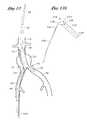
- FIG. 17is a representation of the system as in FIG. 16, with the ipsilateral limb deployed.
- FIG. 18is an exploded view of a bifurcated graft in accordance with the present invention, showing a self expandable wire cage separated from an outer polymeric sleeve.
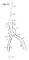
- FIG. 19is schematic representation of the bifurcated graft in accordance with one embodiment of the present invention, showing an expansion spring.
- FIG. 20is plan view of a formed wire useful for rolling into a multi-segmented wire cage in accordance with the present invention.
- This inventionrelates to a delivery catheter and graft system for deploying a bifurcated vascular graft, which allows deployment of the graft from a single vascular access site.
- a related technique using two access sitesis disclosed in co-pending patent application Ser. No. 08/802,478 entitled Bifurcated Vascular Graft and Method and Apparatus for Deploying Same, filed Feb. 20, 1997, the disclosure of which is incorporated in its entirety herein by reference.
- an embodiment of the deployment system 10is depicted in situ at the bifurcation of the aorta into the ipsilateral iliac 20 (in which the deployment system 10 resides) and the contralateral iliac 26 .
- the illustrated deployment system 10employs an over-the-wire coaxial design with three inter-moving elements and, in one embodiment, a thermal or electrical conduit as will be described.
- the deployment system 10is percutaneously (or surgically) inserted into a first access site such as a femoral artery puncture (not illustrated).
- the system 10is advanced distally along a guidewire through the ipsilateral iliac 20 and into the aorta 22 , until positioned as generally illustrated in FIG. 1, spanning the site of an aortic aneurysm 24 .
- the deployment system 10has an overall length from proximal to distal end generally within the range of from about 90 cm to about 110 cm.
- proximal and distalshall be defined from the perspective of the delivery system 10 .
- proximalis in the direction of the control end of the system (not illustrated) and distal is in the direction of the distal tip 32 .
- the illustrated deployment system 10includes an inner core 30 , a middle core 40 , an outer sheath 50 , and a contralateral graft actuator 60 .
- the inner core 30is preferably a thin-walled tube designed to track over a guidewire, such as a standard 0.035 inch guidewire.
- the inner core 30preferably has as small an outside diameter as possible to minimize the overall outside diameter of the delivery catheter, while at the same time providing sufficient column strength to permit distal axial advancement of the tapered tip 32 and tubular housing 33 to deploy the main trunk of the prosthesis as will be discussed.
- a section of stainless steel hypotubehaving an inside diameter of about 0.042 inches, an outside diameter of about 0.058 inches, and an overall length of about 95 cm, depending upon the length of the delivery catheter, has been found suitable for this purpose.
- the device 10has a soft tapered tip 32 secured to the distal end of inner core 30 .
- Tapered tip 32facilitates insertion and atraumatic navigation of the vasculature.
- the tapered tip 32can be made from any of a variety of polymeric materials well known in the medical device arts, such as polyethylene, nylon, PTFE, and PEBAX.
- the distal tapered tip 32tapers in one embodiment from an outside diameter of about 0.225 inches at its proximal end to an outside diameter of about 0.070 inch at its distal end.
- the overall length of the distal tip 32 in one embodiment of the deployment system 10is about 3 inches.
- the length and rate of taper of the distal tip 32can be varied within the range of from about 1 ⁇ 2 inch to about 4 or 5 inches, depending upon the desired tractability and flexibility characteristics.
- a tubular housing 33extends proximally from and is attached to or is a proximal extension of the distal tip 32 .
- the tubular housing 33 and distal tip 32are connected to the inner core 30 , so that distal advancement of the inner core 30 will also distally advance the tip 32 and housing 33 .
- the tubular housing 33serves as a sheath for retaining the compressed main body of the bifurcated graft of the present invention.
- the tubular housing 33comprises a polyolefin extrusion having a length of about 15 cm an inside diameter of about 0.210 inches and an outside diameter of about 0.225 inches.
- the distal end of the tubular housing 33is secured to the proximal end of the distal tip 32 such as by heat shrinking, thermal bonding, adhesive bonding, and/or any of a variety of other securing techniques known in the art.
- the tip 32 and housing 33may be integrally formed such as by extrusion followed by heated stretching or other technique to taper the distal end.
- the distal tip 32is preferably also directly or indirectly connected to the inner core 30 such as by a friction fit, adhesives or thermal bonding.
- the middle core 40comprises an elongate flexible tubular body adapted to axially slidably track over the inner core 30 .
- the middle core 40comprises a polyethylene or PTFE extrusion having an inside diameter of about 0.180 inches and an outside diameter of about 0.220 inches.
- the inner and/or outer surfaces of the middle core 40may be further provided with a lubricious coating such as paralene, silicone, PTFE or others well known in the art.
- the middle core 40has a tubular distal end to slidably receive ipsilateral iliac limb 72 of the graft as will be discussed (See, e.g., FIGS. 3 and 4 ).
- the middle core 40may be tubular throughout its length, or may comprise a pull wire or ribbon throughout a proximal portion thereof (See, e.g., FIG. 5 ).
- the tubular distal segmenthas an axial length of at least about 5 cm or longer depending upon the dimensions of the graft.
- the outer core 50comprises an elongate, flexible tubular body, slidably positioned over the middle core 40 . Outer core 50 also entraps the restrained contralateral limb against the outside surface of middle core 40 in the illustrated embodiment.
- the outer sheath 50comprises extruded PTFE, having an Outside diameter of about 0.250 inches and an inside diameter of about 0.230 inches.
- the outer sheath 50has an axial length within the range of from about 40 inches to about 55 inches.
- the distal end 52 of the outer sheath 50is located at least about 16 cm proximally of the distal end 34 of the tapered tip 32 .
- the outer sheath 50may be provided at its proximal end (not shown) with a manifold, having a hemostatic valve and access ports, such as for the infusion of drugs or contrast media as will be understood by those of skill in the art.
- the contralateral limb 70separates from the middle core 40 and inclines laterally due to the resilience of the wire cage in the contralateral limb 70 .
- the limbsmay separate due to an internal separation spring connected to the ipsilateral and contralateral limbs, with the apex of the spring located at the bifurcation. See, e.g., FIG. 14)
- the ipsilateral limb (hidden)remains sheathed by the middle core 40 .
- the main body of the stent graftremains sheathed by the tubular housing 33 .
- the self-expandable ipsilateral limb 72 of the graftis deployed within the ipsilateral iliac 20 , as illustrated in FIG. 4, by proximally retracting the middle core 40 .
- the middle core 40comprises a thin-walled length of PTFE tubing having an outside diameter of about 0.215 inches. The middle core 40 moves axially with respect to the inner core 30 .
- a variation of the middle core 40 designconsists of a relatively short ipsilateral sheath section 44 , which is necked down such as by heat shrinking to secure the ipsilateral sheath section 44 to a longer tubular extension 46 , the combination forming the modified middle core 40 .
- the ipsilateral limb 72 of the graftis deployed by proximally withdrawing the tubular extension 46 so that retraction of the ipsilateral sheath section 44 releases the self-expandable wire cage from its compressed state in the ipsilateral limb 72 .
- the length of sheath 44is generally in the range of from about 5 cm to about 9 cm. In one embodiment in which the ipsilateral limb 72 has a length of about 5.5 cm, the sheath 44 has a length of about 5.5 cm.
- the self-expanding aortic trunk portion, or main body 74 of the graft 76is released from its compressed state within the tubular housing 33 by distally advancing the inner core 30 . Because the tubular housing 33 and distal tip 32 are attached to the inner core 30 , the distal movement of the inner core causes the housing 33 to advance, thereby permitting the main body 74 of the graft to expand to its larger, deployed diameter.
- the contralateral limb 70 of the graft 76may then be expanded within the contralateral iliac 26 by activation of the contralateral graft actuator 60 .
- expansionmay be accomplished by heating the contralateral limb via actuator 60 .
- transition temperaturewhich may be between 40-60° C. for Nitinol
- the compressed wireexpands to its predetermined tubular shape.
- power from a DC power supply or RF generatoris transferred to the wire support cage from the proximal end of the deployment system, by way of an electrically conductive graft actuator 60 .
- electrically conductive graft actuator 60Any of a wide variety of electrical conductors can be utilized for the electrically-conductive graft actuator 60 , including solid wire, braided filaments and others as will be understood by those of skill in the art.
- a solid wire having a cross section of about 0.010 inches and an insulating layer comprising polyimide and having a thickness of about 0.002 inchesis utilized.
- the electrical conductormay contact the memory alloy wire of the graft via clasp, jaws, wire bending or intermeshing, a third segment, welds, or free contact.
- the electrically conductive actuator wireis preferably coated with a polymer material providing both electrical and thermal resistance.
- the thickness of the coatingis preferably between about 0.001 inches to about 0.0015 inches.
- the polymer materials that can be used for the coatingare materials such as PTFE, polyimide and polyester.
- the coatingpreferably provides insulation at temperatures ranging from about 20° C. to about 60° C.
- the electrical conductoris also retracted with the deployment system.
- the deployment system 10including the distal tip 32 and tubular housing 33 , the inner core 30 and middle core 40 , and the actuator 60 , are proximally retracted through the expanded bifurcated graft 76 .
- the deployment systemmay thereafter be proximally withdrawn from the patient by way of the single vascular access site, leaving only the fully deployed bifurcated graft 76 spanning the aortic aneurysm 24 as shown in FIG. 9 .
- any of a variety of structurescan be utilized to restrain the contralateral limb 70 , during placement of the graft, and thereafter release or expand the contralateral limb 70 within the contralateral iliac.
- all such restraining and release mechanismsare operated through the single vascular access site as has been discussed.
- a release wireshall mean any suitable structure including a wire or cord.
- a small diameter wire (e.g. 0.010 inch diameter) or low profile ribbon (e.g. 0.001 inch by 0.003 inch) restraint 100may be wrapped or woven around a self-expanding stent cage to hold it in a collapsed profile for placement within the contralateral limb 70 as illustrated in FIG. 10 .
- the main body 74 and ipsilateral limb 72 of the prosthesisare configured and deployed in the same manner as described previously.
- the restraint 100can be retracted from the proximal end of the deployment system, releasing the contralateral limb and allowing it to expand.
- the deployment system including the restraint 100is then removed from the single access port.
- a water soluble adhesivecan be utilized to encapsulate the compressed contralateral limb 70 .
- a water soluble adhesivecan be utilized to encapsulate the compressed contralateral limb 70 .
- exposure to bloodcauses the dissolvable restraint material to dissolve, eventually permitting the contralateral limb 70 to expand to its implanted diameter.
- biomaterialswhich are absorbable in an aqueous environment over different time intervals are known, including a variety of compounds in the polyglycolic acid family, as will be understood by those of skill in the art.
- the bioadhesive or other bioabsorbable restraint compound mastpermit sufficient time for the contralateral limb 70 to be properly positioned within the contralateral iliac 26 before releasing the contralateral limb 70 as will be appreciated by those of skill in the art.
- a tubular sheath 102is used to restrain the contralateral limb as shown in FIGS. 11 and 12.
- the contralateral limb 70is deployed by proximally retracting a release wire 103 .
- the proximal movement of the release wire 103causes the contralateral sheath 102 to advance inferiorly into the contralateral iliac, thereby releasing the self-expandable wire cage within the contralateral limb as depicted in FIG. 12 .
- the release wire 103comprises a proximal ipsilateral segment 104 and a distal, contralateral segment 106 .
- Ipsilateral segment 104 and contralateral segment 106are joined at an apex 108 .
- Apex 108may be a bend in the release wire 103 , or a joint such as for securing two separate segments together.
- the release wire 103particularly in the region of the apex 108 , must have sufficient structural integrity that proximal retraction of the proximal end of release wire 103 will cause movement of the contralateral segment 106 in the inferior direction (down the contralateral iliac away from the aorta).
- the contralateral iliac segment 106is secured at its distal end to the tubular sheath 102 .
- the release wire 103may be formed from any of a variety of materials and dimensions as will be apparent in view of the disclosure herein. In one embodiment a circular cross-section, solid wire having a diameter in the range of about 0.020 inches to about 0.030 inches may be used.
- the release wire 103is advanced distally, thereby drawing the tubular sheath 102 in a superior direction through the expanded contralateral limb of the graft and towards the aorta.
- a medially-directed bias exerted by apex 108urges the tubular sheath 102 in the direction of the ipsilateral iliac.
- the release wire 103may be withdrawn.
- the release wire 103may simply be proximally withdrawn, drawing the tubular sheath 102 through the contralateral graft segment 70 as will be appreciated by those of skill in the art in view of the disclosure herein.
- a wire without an apexwhich is fastened to the distal tip of the sheath 102 , may be retracted, thereby pulling the contralateral limb sheath from outside in, through and off of the contralateral limb and out through the lumen.
- the contralateral iliac segment 70is restrained in its insertion profile by a peelable sheath 110 .
- the peelable sheath 110can be removed to release the contralateral iliac segment 70 by proximal retraction, preferably into the catheter.
- FIGS. 13 through 17The use of one embodiment of a peelable sheath for restraining and deploying contralateral iliac segment 70 is illustrated in FIGS. 13 through 17.
- FIG. 13there is illustrated a deployment device positioned within an aneurysm 24 in the aorta 22 at the bifurcation of the ipsilateral iliac 20 and contralateral iliac 26 .
- the main body 74 of the grafthas already been deployed within the aorta 22 in accordance with techniques previously disclosed.
- the outer sheath 40Following retraction of the outer sheath 40 in a proximal direction to release the constrained contralateral iliac segment 70 for positioning within the contralateral iliac 26 , (as illustrated in FIG. 13 ), the outer sheath 40 is distally advanced to the bifurcation as illustrated in FIG. 14 . At this point, the system is prepared for release of the peelable sheath 110 .
- a peelable sheath 110for releasably restraining the contralateral iliac segment 70 .
- the peelable sheath 110comprises a tubular body 112 having a proximal (superior) end 114 and a distal (inferior) end 116 .
- the peelable sheath 110is secured to a contralateral graft actuator 60 such as a release wire 103 .
- the release wire 103 in the illustrated embodimentis secured by way of a joint 120 to the proximal end 114 of the peelable sheath 110 , and extends through the middle core 40 to the proximal end of the catheter.
- the peelable sheath 110may be made from any of a variety of thin, tearable materials as will be apparent to those of skill in the art in view of the disclosure herein.
- the materialexhibits sufficient strength that it will restrain the self expandable contralateral iliac segment 70 while at the same time maintaining a low cross sectional profile and also permitting tearing to occur with a minimal amount of traction required on the release wire 103 .
- the peelable sheath 110comprises a PTFE tube having a wall thickness of about 0.011′′, an outside diameter of about 0.196′′ and a length from the peel start point 130 to the distal end 116 of about 5.0 cm. The overall length from the joint 120 to the distal end 116 is about 6.0 cm. Specific dimensions may be optimized for any particular device as will be understood in the art.
- Other thin wall tearable materialsmay also be used, such as PET, HDPE, or PE.
- the distal end of the outer sheath 40provides a fulcrum for minimizing injury to the adjacent tissue as proximal traction is applied to the release wire 103 .
- Proximal retraction of the release wire 103pulls the peelable sheath 110 in a proximal (superior) direction, around the bifurcation and down into the tubular outer sheath 40 .
- retraction of the pull wire 103slides the tubular body 112 superiorly along the contralateral iliac segment 70 such that the contralateral iliac segment 70 is released from the inferior end first.
- proximal retraction of the release wire 103causes the peelable sheath 110 to tear or split thereby permitting complete retraction of the peelable sheath 110 from the contralateral iliac segment 70 as illustrated in FIG. 16 .
- the middle core 40 and/or a separate ipsilateral limb cover 44may be proximally retracted to deploy the ipsilateral limb 72 .
- the release wire 103may extend through the outer core 50 or the middle core 40 , through a dedicated lumen in the wall of either, or outside of the catheter as may be desired for particular product designs.
- the peelable sheath 110 in the foregoing embodimentwas disclosed as restraining the contralateral iliac limb, the peelable sheath may be used on any of the contralateral, ipsilateral, or main branch portions of the graft.
- the main body portion of the graftis restrained within the graft tube 33 , and each of the contralateral and ipsilateral iliac graft branches are restrained by a peelable sheath.
- all three portions of the graftare restrained by peelable sheaths.
- the main graft body and the contralateral iliac limb portions of the graftare restrained by first and second peelable sheaths and the ipsilateral portion of the graft is restrained by a proximally retractable sleeve as has been disclosed previously herein.
- first and second peelable sheathsand the ipsilateral portion of the graft is restrained by a proximally retractable sleeve as has been disclosed previously herein.
- FIG. 18an embodiment of a self-expanding bifurcated prosthesis in accordance with the present invention is shown having a polymeric sleeve 80 and a tubular wire support 90 .
- Many of the features of the self-expandable graft of the present inventionare disclosed in co-pending U.S. patent application Ser. No. 09/100,481 entitled “Self Expanding Bifurcated Endovascular Prosthesis,” filed Jun. 19, 1998, and copending U.S. patent application Ser. No. 09/210,280, entitled “Endoluminal Vascular Prosthesis,” filed Dec. 11, 1998, the disclosures of which are incorporated in their entirety herein by reference.
- the polymeric sleeve 80may be situated concentrically outside of the tubular wire support 90 .
- other embodimentsmay include a sleeve situated instead concentrically inside the wire support or on both of the inside and the outside of the wire support.
- the wire supportmay be embedded within a polymeric matrix that makes up the sleeve.
- the sleevemay be attached to the wire support by any of a variety of means, including laser bonding, adhesives, clips, sutures, dipping or spraying or others, depending upon the composition of the sleeve and overall graft design.
- the polymeric sleevemay be formed from any of a variety of synthetic polymeric materials, or combinations thereof, including PTFE, PE, PET, Urethane, Dacron, nylon, polyester or woven textiles.
- the sleeve materialexhibits relatively low inherent elasticity, or low elasticity out to the intended enlarged diameter of the wire cage.
- the sleeve materialpreferably has a thin profile, such as no larger than about 0.002 inches to about 0.005 inches.
- the material of the sleeveis sufficiently porous to permit in-growth of endothelial cells, thereby providing more secure anchorage of the prosthesis and potentially reducing flow resistance, shear forces, and leakage of blood around the prosthesis.
- Porosity in polymeric sleeve materialsmay be estimated by measuring water permeability as a function of hydrostatic pressure, which will preferably range from about 3 to 6 psi.
- the porosity characteristics of the polymeric sleevemay be either homogeneous throughout the axial length of the prosthesis, or may vary according to the axial position along the prosthesis. For example, at least a distal portion and right and left proximal portions of the prosthesis will seat against the native vessel walls, proximally and distally of the aneurysm. In at least these proximal and distal portions, the prosthesis preferably encourages endothelial growth, or, at least, permits endothelial growth to infiltrate portions of the prosthesis in order to enhance anchoring and minimize leakage. For the central portion of the prosthesis, which spans the aneurysm, anchoring is less of an issue. Instead, minimizing blood flow through the prosthesis wall becomes a primary objective. Thus, in a central zone of the prosthesis, the polymeric sleeve may either be nonporous, or provided with pores that minimize or prevent leakage.
- a multi-zoned prosthesismay also be provided in accordance with the present invention by positioning a tubular sleeve on a central portion of the prosthesis, such that it spans the aneurysm to be treated, but leaving the wire support in the proximal and distal attachment zones exposed.
- the exposed wiresare positioned in contact with the vessel wall both proximally and distally of the aneurysm, such that the wire, over time, becomes embedded in cell growth on the interior surface of the vessel wall.
- the sleeve and/or the wire supportis stepped or tapered, having a relatively larger expanded diameter at the proximal end compared to the distal ends.
- the tapered designmay allow the prosthesis to conform better to the natural decreasing distal cross section of the aorta and iliac arteries to reduce the risk of leakage and graft migration and potentially create better flow dynamics.
- the tubular wire supportcomprises a main body 92 for traversing the aorta and a first, ipsilateral iliac limb 94 , and a secondary component for extending into the second, contralateral iliac limb 96 .
- the contralateral limb cagemay be constructed from a memory alloy wire such as Nitinol as has been discussed.
- the main body and ipsilateral limb structuresmay be constructed from a non-memory alloy wire.
- one embodiment of the prosthesis 76is shown, wherein the limbs expand laterally away from one another due to an expansion spring 120 , comprising an apex and first and second leg portions.
- the leg portionsare connected to the wire cage 90 of both the ipsilateral and contralateral limbs at connection point 122 .
- the apex 124 of the expansion spring 120is located at the bifurcation.
- the wire cageis formed from one or more lengths of wire into a series of straight struts separated by apexes into a zig-zag pattern.
- the contralateral wire cagemay also be constructed from one or more zig-zag wires as illustrated.
- the connectors 98collectively produce a generally axially extending backbone that adds axial strength to the prosthesis.
- the wire supportis formed in a plurality of discrete segments, connected together and oriented about a common axis. A connector wire 98 connects adjacent segments together.
- Opposing wire apexes of adjacent segmentscan be connected in any of a variety of ways including circumferentially extending sutures, solder joints, wire loops and any of a variety of interlocking relationships, such as those disclosed in copending U.S. patent application Ser. No. 09/210,280, filed Dec. 11, 1998, entitled “Endoluminal Vascular Prosthesis”, the disclosure of which is incorporated in its entirety herein by reference.
- the contralateral limb cagemay be joined to the main body and ipsilateral limb component by similar sutures, solder joints, wire loops and/or interlocking relationships.
- the segmented configuration of the tubular wire supportsfacilitates a great deal of flexibility.
- Each segment, though joined to adjacent segments,may be independently engineered to yield desired parameters.
- Each segmentmay range in axial length from about 0.3 to about 5 cm. Generally, the shorter their length the greater the radial strength.
- the primary component of an endoluminal prosthesismay include from about 2 to about 50 segments, preferably from about 8 to about 16 segments.
- each of the components of the tubular wire supportcan be varied considerably in diameter, length, and expansion coefficient, depending upon the intended application.
- the aorta trunk portionwill have a length within the range of from about 5 cm to about 12 cm, and, typically within the range of from about 9 cm to about 10 cm.
- the unconstrained outside expanded diameter this portionwill typically be within the range of from about 20 mm to about 40 mm.
- the unconstrained expanded outside diameter of this portioncan be constant or substantially constant throughout its length, or can be tapered from a relatively larger diameter at the proximal end to a relatively smaller diameter at the bifurcation.
- the diameter of the distal endwill be on the order of no more than about 95% and, preferably, no more than about 85% of the diameter of the proximal end of the aortic trunk portion.
- Different zones of the prosthesiscan be provided with differing expanded diameters. Further, the different zones can be provided with a different radial expansion force, such as ranging from about 2 lbs. to about 8 lbs.
- the proximal zoneis provided with a greater radial force than the central zone and/or distal zone.
- a greater radial forcecan be provided in any of a variety of manners, such as through the use of additional wire bends and wall sections. Alternatively, additional spring force can be achieved through the use of a heavier gauge wire.
- Increased radial force and expansion diameter in the proximal and distal regions relative to a central regioncan be achieved by tightening a circumferential suture such that the central region is retained under compression even in the expanded configuration. By omitting a circumferential suture at the proximal end and/or distal ends of the prosthesis, the proximal end and distal ends will flair radially outwardly to a fully expanded configuration.
- the wire for the main body and ipsilateral limb cagesmay be made from any of a variety of different alloys, such as elgiloy or MP35N, or other alloys which include nickel, titanium, tantalum, or stainless steel, high Co—Cr alloys or other temperature sensitive materials.
- elgiloy or MP35Nor other alloys which include nickel, titanium, tantalum, or stainless steel, high Co—Cr alloys or other temperature sensitive materials.
- an alloycomprising Ni 15%, Co 40%, Cr 20%, Mo 7% and balance Fe may be used.
- the tensile strength of suitable wireis generally above about 300 K psi and often between about 300 and about 340 K psi for many embodiments.
- a Chromium-Nickel-Molybdenum alloysuch as that marketed under the name Conichrom (Fort Wayne Metals, Indiana) has a tensile strength ranging from 300 to 320 K psi, elongation of 3.5-4.0% and breaking load at approximately 80 lbs. to 70 lbs.
- at least the contralateral limb cagemay be constructed from a memory alloy such as Nitinol, which will remain in a small profile until heated to the memory alloy's transition temperature, at which point the contralateral limb cage expands to a predisposed shape.
- both the memory and non-memory alloy wiresmay be treated with a plasma coating and be provided with or without additional coatings such as PTFE, Teflon, Perlyne, drugs, and others as will be understood by those of skill in the art.
- wire gaugeIn addition to segment length and bend configuration, another determinant of radial strength is wire gauge.
- the radial strengthmeasured at 50% of the collapsed profile, preferably ranges from about 2 lb. to 8 lb., and generally from about 4 lb. to about 5 lb. or more.
- Preferred wire diameters in accordance with the present inventionrange from about 0.004 inches to about 0.020 inches. More preferably, the wire diameters range from about 0.006 inches to about 0.018 inches. In general, the greater the wire diameter, the greater the radial strength for a given wire layout.
- the wire gaugecan be varied depending upon the application of the finished graft, in combination with/or separate from variation in other design parameters.
- a wire diameter of approximately 0.018 inchesmay be useful in the aorta trunk portion of a graft, while a smaller diameter such as 0.006 inches might be useful for the iliac limb segment.
- the wire diameteris tapered throughout from the proximal to distal ends.
- the wire diametermay be tapered incremental or stepped down, or stepped up, depending on the radial strength requirements of each particular clinical application.
- the diameter of the wire in the iliac branchesis no more than about 80%, preferably no more than about 50%, and optimally no more than about 35% of the diameter of the wire in the aortic trunk. This permits increased flexibility of the graft in the region of the iliac branches, which has been determined by the present inventors to be clinically desirable.
- the collapsed prosthesis in accordance with the present inventionhas a diameter in the range of about 2 to about 10 mm.
- the maximum diameter of the collapsed prosthesisis in the range of about 3 to 6 mm (12 to 18 French).
- the delivery catheter including the prosthesiswill be 19 F, 16 F, 14 F, or smaller.
- the expanded endoluminal vascular prosthesisradially self-expands to a diameter anywhere in the range of from about 20 to about 40 mm, corresponding to expansion ratios of about 1:2 to 1:20.
- the expansion ratiosrange from about 1:4 to 1:8, more preferably from about 1:4 to 1:6.
Landscapes
- Health & Medical Sciences (AREA)
- Engineering & Computer Science (AREA)
- Biomedical Technology (AREA)
- Heart & Thoracic Surgery (AREA)
- Public Health (AREA)
- Transplantation (AREA)
- Cardiology (AREA)
- Veterinary Medicine (AREA)
- Oral & Maxillofacial Surgery (AREA)
- Vascular Medicine (AREA)
- Life Sciences & Earth Sciences (AREA)
- Animal Behavior & Ethology (AREA)
- General Health & Medical Sciences (AREA)
- Gastroenterology & Hepatology (AREA)
- Pulmonology (AREA)
- Prostheses (AREA)
- Ventilation (AREA)
Abstract
Description
Claims (18)
Priority Applications (5)
| Application Number | Priority Date | Filing Date | Title |
|---|---|---|---|
| US09/795,993US6663665B2 (en) | 1999-03-11 | 2001-02-28 | Single puncture bifurcation graft deployment system |
| US10/690,227US7691135B2 (en) | 1999-03-11 | 2003-10-21 | Single puncture bifurcation graft deployment system |
| US10/722,367US8034100B2 (en) | 1999-03-11 | 2003-11-25 | Graft deployment system |
| US12/732,095US8167925B2 (en) | 1999-03-11 | 2010-03-25 | Single puncture bifurcation graft deployment system |
| US13/269,332US8568466B2 (en) | 1999-03-11 | 2011-10-07 | Graft deployment system |
Applications Claiming Priority (2)
| Application Number | Priority Date | Filing Date | Title |
|---|---|---|---|
| US09/266,661US6261316B1 (en) | 1999-03-11 | 1999-03-11 | Single puncture bifurcation graft deployment system |
| US09/795,993US6663665B2 (en) | 1999-03-11 | 2001-02-28 | Single puncture bifurcation graft deployment system |
Related Parent Applications (1)
| Application Number | Title | Priority Date | Filing Date |
|---|---|---|---|
| US09/266,661DivisionUS6261316B1 (en) | 1999-03-11 | 1999-03-11 | Single puncture bifurcation graft deployment system |
Related Child Applications (3)
| Application Number | Title | Priority Date | Filing Date |
|---|---|---|---|
| US10/690,227ContinuationUS7691135B2 (en) | 1999-03-11 | 2003-10-21 | Single puncture bifurcation graft deployment system |
| US10/722,367Continuation-In-PartUS8034100B2 (en) | 1999-03-11 | 2003-11-25 | Graft deployment system |
| US10/722,367ContinuationUS8034100B2 (en) | 1999-03-11 | 2003-11-25 | Graft deployment system |
Publications (2)
| Publication Number | Publication Date |
|---|---|
| US20010007954A1 US20010007954A1 (en) | 2001-07-12 |
| US6663665B2true US6663665B2 (en) | 2003-12-16 |
Family
ID=23015480
Family Applications (4)
| Application Number | Title | Priority Date | Filing Date |
|---|---|---|---|
| US09/266,661Expired - LifetimeUS6261316B1 (en) | 1999-03-11 | 1999-03-11 | Single puncture bifurcation graft deployment system |
| US09/795,993Expired - LifetimeUS6663665B2 (en) | 1999-03-11 | 2001-02-28 | Single puncture bifurcation graft deployment system |
| US10/690,227Expired - Fee RelatedUS7691135B2 (en) | 1999-03-11 | 2003-10-21 | Single puncture bifurcation graft deployment system |
| US12/732,095Expired - Fee RelatedUS8167925B2 (en) | 1999-03-11 | 2010-03-25 | Single puncture bifurcation graft deployment system |
Family Applications Before (1)
| Application Number | Title | Priority Date | Filing Date |
|---|---|---|---|
| US09/266,661Expired - LifetimeUS6261316B1 (en) | 1999-03-11 | 1999-03-11 | Single puncture bifurcation graft deployment system |
Family Applications After (2)
| Application Number | Title | Priority Date | Filing Date |
|---|---|---|---|
| US10/690,227Expired - Fee RelatedUS7691135B2 (en) | 1999-03-11 | 2003-10-21 | Single puncture bifurcation graft deployment system |
| US12/732,095Expired - Fee RelatedUS8167925B2 (en) | 1999-03-11 | 2010-03-25 | Single puncture bifurcation graft deployment system |
Country Status (6)
| Country | Link |
|---|---|
| US (4) | US6261316B1 (en) |
| EP (1) | EP1159024B1 (en) |
| AT (1) | ATE342698T1 (en) |
| AU (1) | AU3731500A (en) |
| DE (1) | DE60031381T2 (en) |
| WO (1) | WO2000053251A1 (en) |
Cited By (60)
| Publication number | Priority date | Publication date | Assignee | Title |
|---|---|---|---|---|
| US20030236565A1 (en)* | 2002-06-21 | 2003-12-25 | Dimatteo Kristian | Implantable prosthesis |
| US20040098084A1 (en)* | 2002-09-02 | 2004-05-20 | Cook Incorporated | Branch grafting device and method |
| US20040186508A1 (en)* | 1998-03-05 | 2004-09-23 | Adams Daniel O. | Dilation and stent delivery system for bifurcation lesions |
| US20050154444A1 (en)* | 2003-10-10 | 2005-07-14 | Arshad Quadri | System and method for endoluminal grafting of bifurcated and branched vessels |
| US20050228480A1 (en)* | 2004-04-08 | 2005-10-13 | Douglas Myles S | Endolumenal vascular prosthesis with neointima inhibiting polymeric sleeve |
| US7105018B1 (en) | 2002-12-30 | 2006-09-12 | Advanced Cardiovascular Systems, Inc. | Drug-eluting stent cover and method of use |
| US7144422B1 (en) | 2002-11-13 | 2006-12-05 | Advanced Cardiovascular Systems, Inc. | Drug-eluting stent and methods of making the same |
| US20070010780A1 (en)* | 2005-06-27 | 2007-01-11 | Venkataramana Vijay | Methods of implanting an aorto-coronary sinus shunt for myocardial revascularization |
| US20070010781A1 (en)* | 2005-06-27 | 2007-01-11 | Venkataramana Vijay | Implantable aorto-coronary sinus shunt for myocardial revascularization |
| US20070050015A1 (en)* | 2005-08-25 | 2007-03-01 | Scimed Life Systems, Inc. | Endoluminal prosthesis adapted to deployment in a distorted branched body lumen and method of deploying the same |
| WO2006044637A3 (en)* | 2004-10-13 | 2007-05-03 | Anvil Medical Inc | Stepped balloon catheter for treating vascular bifurcations |
| US20070299494A1 (en)* | 2006-06-23 | 2007-12-27 | Stanislaw Zukowski | Branched stent delivery system |
| US7435255B1 (en) | 2002-11-13 | 2008-10-14 | Advnaced Cardiovascular Systems, Inc. | Drug-eluting stent and methods of making |
| US7481834B2 (en) | 2003-04-14 | 2009-01-27 | Tryton Medical, Inc. | Stent for placement at luminal os |
| US20100063578A1 (en)* | 2008-09-05 | 2010-03-11 | Aga Medical Corporation | Bifurcated medical device for treating a target site and associated method |
| US7717953B2 (en) | 2004-10-13 | 2010-05-18 | Tryton Medical, Inc. | Delivery system for placement of prosthesis at luminal OS |
| US7731747B2 (en) | 2003-04-14 | 2010-06-08 | Tryton Medical, Inc. | Vascular bifurcation prosthesis with multiple thin fronds |
| WO2010064244A2 (en) | 2008-12-04 | 2010-06-10 | Inverthis Ltd | Delivery system for delivering a graft from the middle thereof |
| US7758630B2 (en) | 2003-04-14 | 2010-07-20 | Tryton Medical, Inc. | Helical ostium support for treating vascular bifurcations |
| US20100318174A1 (en)* | 1998-12-11 | 2010-12-16 | Endologix, Inc. | Implantable vascular graft |
| US7972372B2 (en) | 2003-04-14 | 2011-07-05 | Tryton Medical, Inc. | Kit for treating vascular bifurcations |
| US8034100B2 (en) | 1999-03-11 | 2011-10-11 | Endologix, Inc. | Graft deployment system |
| US8066755B2 (en) | 2007-09-26 | 2011-11-29 | Trivascular, Inc. | System and method of pivoted stent deployment |
| US8083791B2 (en) | 2003-04-14 | 2011-12-27 | Tryton Medical, Inc. | Method of treating a lumenal bifurcation |
| US8083789B2 (en) | 2007-11-16 | 2011-12-27 | Trivascular, Inc. | Securement assembly and method for expandable endovascular device |
| US8088060B2 (en) | 2000-03-15 | 2012-01-03 | Orbusneich Medical, Inc. | Progenitor endothelial cell capturing with a drug eluting implantable medical device |
| US20120101563A1 (en)* | 2009-05-26 | 2012-04-26 | Qing Zhu | Delivery system for branched stent graft |
| US8167925B2 (en) | 1999-03-11 | 2012-05-01 | Endologix, Inc. | Single puncture bifurcation graft deployment system |
| US8216295B2 (en) | 2008-07-01 | 2012-07-10 | Endologix, Inc. | Catheter system and methods of using same |
| US8226701B2 (en) | 2007-09-26 | 2012-07-24 | Trivascular, Inc. | Stent and delivery system for deployment thereof |
| US8231667B2 (en) | 2002-11-08 | 2012-07-31 | Jacques Séguin | Endoprosthesis for vascular bifurcation |
| US8236041B2 (en) | 2000-05-30 | 2012-08-07 | Biosensors International Group, Ltd. | Noncylindrical stent deployment system for treating vascular bifurcations |
| US8236040B2 (en) | 2008-04-11 | 2012-08-07 | Endologix, Inc. | Bifurcated graft deployment systems and methods |
| US8328861B2 (en) | 2007-11-16 | 2012-12-11 | Trivascular, Inc. | Delivery system and method for bifurcated graft |
| US8366763B2 (en) | 2009-07-02 | 2013-02-05 | Tryton Medical, Inc. | Ostium support for treating vascular bifurcations |
| US8460367B2 (en) | 2000-03-15 | 2013-06-11 | Orbusneich Medical, Inc. | Progenitor endothelial cell capturing with a drug eluting implantable medical device |
| US8641753B2 (en) | 2009-01-31 | 2014-02-04 | Cook Medical Technologies Llc | Preform for and an endoluminal prosthesis |
| US8663309B2 (en) | 2007-09-26 | 2014-03-04 | Trivascular, Inc. | Asymmetric stent apparatus and method |
| US8728143B2 (en) | 1996-06-06 | 2014-05-20 | Biosensors International Group, Ltd. | Endoprosthesis deployment system for treating vascular bifurcations |
| US20140277330A1 (en)* | 2013-03-13 | 2014-09-18 | Cook Medical Technologies Llc | Pre-Loaded Iliac Branch Device and Methods of Deployment |
| US8945202B2 (en) | 2009-04-28 | 2015-02-03 | Endologix, Inc. | Fenestrated prosthesis |
| US8961587B2 (en) | 2009-03-18 | 2015-02-24 | Microport Endovascular (Shanghai) Co., Ltd. | Branched stent graft |
| US8992595B2 (en) | 2012-04-04 | 2015-03-31 | Trivascular, Inc. | Durable stent graft with tapered struts and stable delivery methods and devices |
| US9101501B2 (en) | 1996-06-06 | 2015-08-11 | Biosensors International Group, Ltd. | Bifurcation stent and method of positioning in a body lumen |
| US9387309B2 (en) | 2007-04-23 | 2016-07-12 | Cardioguidance Biomedical, Llc | Guidewire with adjustable stiffness |
| US9498363B2 (en) | 2012-04-06 | 2016-11-22 | Trivascular, Inc. | Delivery catheter for endovascular device |
| US9522217B2 (en) | 2000-03-15 | 2016-12-20 | Orbusneich Medical, Inc. | Medical device with coating for capturing genetically-altered cells and methods for using same |
| US9549835B2 (en) | 2011-03-01 | 2017-01-24 | Endologix, Inc. | Catheter system and methods of using same |
| US9707108B2 (en) | 2010-11-24 | 2017-07-18 | Tryton Medical, Inc. | Support for treating vascular bifurcations |
| US9925031B2 (en) | 2009-12-28 | 2018-03-27 | Cook Medical Technologies Llc | Endoluminal device with kink-resistant regions |
| US10159557B2 (en) | 2007-10-04 | 2018-12-25 | Trivascular, Inc. | Modular vascular graft for low profile percutaneous delivery |
| US10245166B2 (en) | 2008-02-22 | 2019-04-02 | Endologix, Inc. | Apparatus and method of placement of a graft or graft system |
| US10258492B2 (en) | 2017-03-03 | 2019-04-16 | Cook Medical Technologies Llc | Prosthesis delivery system with axially collapsible sheath |
| US10271974B2 (en) | 2011-06-24 | 2019-04-30 | Cook Medical Technologies Llc | Helical stent |
| US10470871B2 (en) | 2001-12-20 | 2019-11-12 | Trivascular, Inc. | Advanced endovascular graft |
| US10500077B2 (en) | 2012-04-26 | 2019-12-10 | Poseidon Medical Inc. | Support for treating vascular bifurcations |
| US10583020B2 (en) | 2015-05-27 | 2020-03-10 | Trivascular, Inc. | Balloon assisted endoluminal prosthesis deployment |
| US11129737B2 (en) | 2015-06-30 | 2021-09-28 | Endologix Llc | Locking assembly for coupling guidewire to delivery system |
| US11324618B2 (en) | 2017-02-28 | 2022-05-10 | Cook Medical Technologies Llc | Delivery system for a preloaded fenestrated device having a ratcheted wire release |
| US11406518B2 (en) | 2010-11-02 | 2022-08-09 | Endologix Llc | Apparatus and method of placement of a graft or graft system |
Families Citing this family (154)
| Publication number | Priority date | Publication date | Assignee | Title |
|---|---|---|---|---|
| US6051020A (en) | 1994-02-09 | 2000-04-18 | Boston Scientific Technology, Inc. | Bifurcated endoluminal prosthesis |
| US5609627A (en)* | 1994-02-09 | 1997-03-11 | Boston Scientific Technology, Inc. | Method for delivering a bifurcated endoluminal prosthesis |
| US6666883B1 (en) | 1996-06-06 | 2003-12-23 | Jacques Seguin | Endoprosthesis for vascular bifurcation |
| EP1723931B1 (en)* | 1996-11-04 | 2012-01-04 | Advanced Stent Technologies, Inc. | Extendible stent apparatus and method for deploying the same |
| US6599316B2 (en)* | 1996-11-04 | 2003-07-29 | Advanced Stent Technologies, Inc. | Extendible stent apparatus |
| US6325826B1 (en)* | 1998-01-14 | 2001-12-04 | Advanced Stent Technologies, Inc. | Extendible stent apparatus |
| US6835203B1 (en) | 1996-11-04 | 2004-12-28 | Advanced Stent Technologies, Inc. | Extendible stent apparatus |
| US7220275B2 (en) | 1996-11-04 | 2007-05-22 | Advanced Stent Technologies, Inc. | Stent with protruding branch portion for bifurcated vessels |
| US7341598B2 (en) | 1999-01-13 | 2008-03-11 | Boston Scientific Scimed, Inc. | Stent with protruding branch portion for bifurcated vessels |
| US6395019B2 (en) | 1998-02-09 | 2002-05-28 | Trivascular, Inc. | Endovascular graft |
| US6077296A (en)* | 1998-03-04 | 2000-06-20 | Endologix, Inc. | Endoluminal vascular prosthesis |
| US6537284B1 (en)* | 1998-10-29 | 2003-03-25 | Kanji Inoue | Device for guiding an appliance |
| US6660030B2 (en) | 1998-12-11 | 2003-12-09 | Endologix, Inc. | Bifurcation graft deployment catheter |
| US8257425B2 (en) | 1999-01-13 | 2012-09-04 | Boston Scientific Scimed, Inc. | Stent with protruding branch portion for bifurcated vessels |
| WO2001035715A2 (en) | 1999-11-18 | 2001-05-25 | Petrus Besselink | Method for placing bifurcated stents |
| US6387120B2 (en)* | 1999-12-09 | 2002-05-14 | Advanced Cardiovascular Systems, Inc. | Stent and catheter assembly and method for treating bifurcations |
| US6602280B2 (en) | 2000-02-02 | 2003-08-05 | Trivascular, Inc. | Delivery system and method for expandable intracorporeal device |
| IL137090A (en)* | 2000-06-29 | 2010-04-15 | Pentech Medical Devices Ltd | Polymeric stent |
| WO2002067816A1 (en)* | 2001-02-26 | 2002-09-06 | Scimed Life Systems, Inc. | Bifurcated stent and delivery system |
| US20030097169A1 (en)* | 2001-02-26 | 2003-05-22 | Brucker Gregory G. | Bifurcated stent and delivery system |
| US6695877B2 (en) | 2001-02-26 | 2004-02-24 | Scimed Life Systems | Bifurcated stent |
| US6733521B2 (en) | 2001-04-11 | 2004-05-11 | Trivascular, Inc. | Delivery system and method for endovascular graft |
| US20040138734A1 (en)* | 2001-04-11 | 2004-07-15 | Trivascular, Inc. | Delivery system and method for bifurcated graft |
| US6761733B2 (en) | 2001-04-11 | 2004-07-13 | Trivascular, Inc. | Delivery system and method for bifurcated endovascular graft |
| US20020188342A1 (en)* | 2001-06-01 | 2002-12-12 | Rykhus Robert L. | Short-term bioresorbable stents |
| JP4377688B2 (en) | 2001-09-04 | 2009-12-02 | マイクロ セラピューティクス, インコーポレイテッド | Occlusion catheter with extensible balloon for use in complex vasculature |
| US20100016943A1 (en) | 2001-12-20 | 2010-01-21 | Trivascular2, Inc. | Method of delivering advanced endovascular graft |
| JP4331610B2 (en) | 2001-12-20 | 2009-09-16 | トリバスキュラー2,インコーポレイティド | Advanced endovascular graft |
| CA2478609C (en)* | 2002-03-07 | 2011-05-17 | Cordis Corporation | Iliac bifurcation balloon catheter |
| US20050256503A1 (en)* | 2002-05-07 | 2005-11-17 | Cardiac Pacemakers, Inc. | Tapered catheter delivery system |
| US6939327B2 (en) | 2002-05-07 | 2005-09-06 | Cardiac Pacemakers, Inc. | Peel-away sheath |
| US20050256508A1 (en)* | 2002-05-07 | 2005-11-17 | Cardiac Pacemakers, Inc. | Guide catheter system having relative markings |
| US7329268B2 (en) | 2002-07-02 | 2008-02-12 | Warsaw Orthopedic, Inc. | Expandable percutaneous sheath |
| KR100893070B1 (en)* | 2002-09-19 | 2009-04-17 | 엘지전자 주식회사 | Method and apparatus for providing and receiving multicast service in wireless communication system |
| EP1585572A4 (en) | 2002-09-20 | 2010-02-24 | Flowmedica Inc | Method and apparatus for intra aortic substance delivery to a branch vessel |
| EP1539291A4 (en) | 2002-09-20 | 2010-03-10 | Flowmedica Inc | Method and apparatus for selective material delivery via an intra-renal catheter |
| US7993325B2 (en)* | 2002-09-20 | 2011-08-09 | Angio Dynamics, Inc. | Renal infusion systems and methods |
| JP2006507872A (en)* | 2002-11-26 | 2006-03-09 | エンドロジックス、インク. | Graft deployment system |
| US20040236290A1 (en)* | 2003-04-23 | 2004-11-25 | Zimmermann Stephan A. | Minimally invasive vascular apparatus modified to minimize scarring at introduction site |
| US7604660B2 (en)* | 2003-05-01 | 2009-10-20 | Merit Medical Systems, Inc. | Bifurcated medical appliance delivery apparatus and method |
| US20050033416A1 (en)* | 2003-05-02 | 2005-02-10 | Jacques Seguin | Vascular graft and deployment system |
| US7101390B2 (en)* | 2003-05-27 | 2006-09-05 | Scimed Life Systems, Inc. | Staged deployment endograft |
| EP1635736A2 (en) | 2003-06-05 | 2006-03-22 | FlowMedica, Inc. | Systems and methods for performing bi-lateral interventions or diagnosis in branched body lumens |
| US20040254628A1 (en)* | 2003-06-13 | 2004-12-16 | Patrice Nazzaro | One-branch stent-graft for bifurcated lumens |
| IES20030539A2 (en)* | 2003-07-22 | 2005-05-18 | Medtronic Vascular Connaught | Stents and stent delivery system |
| US8298280B2 (en) | 2003-08-21 | 2012-10-30 | Boston Scientific Scimed, Inc. | Stent with protruding branch portion for bifurcated vessels |
| US7998186B2 (en) | 2003-10-14 | 2011-08-16 | William A. Cook Australia Pty. Ltd. | Introducer for a side branch device |
| EP1691719B1 (en) | 2003-10-14 | 2016-09-14 | Cook Medical Technologies LLC | Introducer for an iliac side branch device |
| US7803178B2 (en) | 2004-01-30 | 2010-09-28 | Trivascular, Inc. | Inflatable porous implants and methods for drug delivery |
| WO2005091910A2 (en) | 2004-03-04 | 2005-10-06 | Flowmedica, Inc. | Sheath for use in peripheral interventions |
| US8007528B2 (en) | 2004-03-17 | 2011-08-30 | Boston Scientific Scimed, Inc. | Bifurcated stent |
| US8177760B2 (en) | 2004-05-12 | 2012-05-15 | C. R. Bard, Inc. | Valved connector |
| EP1750506A4 (en) | 2004-05-14 | 2010-03-17 | Flowmedica Inc | Bi-lateral local renal delivery for treating congestive heart failure and for bnp therapy |
| CA2565106C (en)* | 2004-05-25 | 2013-11-05 | Chestnut Medical Technologies, Inc. | Flexible vascular occluding device |
| US8617234B2 (en) | 2004-05-25 | 2013-12-31 | Covidien Lp | Flexible vascular occluding device |
| US20060206200A1 (en) | 2004-05-25 | 2006-09-14 | Chestnut Medical Technologies, Inc. | Flexible vascular occluding device |
| CA2758946C (en) | 2004-05-25 | 2014-10-21 | Tyco Healthcare Group Lp | Vascular stenting for aneurysms |
| US8623067B2 (en) | 2004-05-25 | 2014-01-07 | Covidien Lp | Methods and apparatus for luminal stenting |
| JP5054524B2 (en) | 2004-06-08 | 2012-10-24 | アドバンスド ステント テクノロジーズ, インコーポレイテッド | Stent with protruding branch for branch pipe |
| US7641688B2 (en)* | 2004-09-16 | 2010-01-05 | Evera Medical, Inc. | Tissue augmentation device |
| US7244270B2 (en)* | 2004-09-16 | 2007-07-17 | Evera Medical | Systems and devices for soft tissue augmentation |
| US7635383B2 (en)* | 2004-09-28 | 2009-12-22 | Boston Scientific Scimed, Inc. | Rotating stent delivery system for side branch access and protection and method of using same |
| EP1807022A2 (en)* | 2004-11-03 | 2007-07-18 | Jacques Seguin | Vascular graft and deployment system |
| US9427340B2 (en) | 2004-12-14 | 2016-08-30 | Boston Scientific Scimed, Inc. | Stent with protruding branch portion for bifurcated vessels |
| US8128680B2 (en) | 2005-01-10 | 2012-03-06 | Taheri Laduca Llc | Apparatus and method for deploying an implantable device within the body |
| US9034025B2 (en) | 2005-05-23 | 2015-05-19 | Ostial Corporation | Balloon catheters and methods for use |
| AU2005332044B2 (en) | 2005-05-25 | 2012-01-19 | Covidien Lp | System and method for delivering and deploying and occluding device within a vessel |
| US8480728B2 (en) | 2005-05-26 | 2013-07-09 | Boston Scientific Scimed, Inc. | Stent side branch deployment initiation geometry |
| US8317855B2 (en) | 2005-05-26 | 2012-11-27 | Boston Scientific Scimed, Inc. | Crimpable and expandable side branch cell |
| US8795348B2 (en)* | 2005-06-14 | 2014-08-05 | Boston Scientific Scimed, Inc. | Medical devices and related methods |
| WO2007016166A2 (en)* | 2005-07-27 | 2007-02-08 | Cook Critical Care Incorporated | Stent/graft device and method for open surgical placement |
| US20070043420A1 (en)* | 2005-08-17 | 2007-02-22 | Medtronic Vascular, Inc. | Apparatus and method for stent-graft release using a cap |
| US8702777B2 (en)* | 2005-08-22 | 2014-04-22 | Incept, Llc | Steep-taper flared stents and apparatus and methods for delivering them |
| US8043366B2 (en) | 2005-09-08 | 2011-10-25 | Boston Scientific Scimed, Inc. | Overlapping stent |
| US8038706B2 (en) | 2005-09-08 | 2011-10-18 | Boston Scientific Scimed, Inc. | Crown stent assembly |
| US7731741B2 (en) | 2005-09-08 | 2010-06-08 | Boston Scientific Scimed, Inc. | Inflatable bifurcation stent |
| US20070112418A1 (en) | 2005-11-14 | 2007-05-17 | Boston Scientific Scimed, Inc. | Stent with spiral side-branch support designs |
| US8435284B2 (en) | 2005-12-14 | 2013-05-07 | Boston Scientific Scimed, Inc. | Telescoping bifurcated stent |
| US8343211B2 (en) | 2005-12-14 | 2013-01-01 | Boston Scientific Scimed, Inc. | Connectors for bifurcated stent |
| US7540881B2 (en) | 2005-12-22 | 2009-06-02 | Boston Scientific Scimed, Inc. | Bifurcation stent pattern |
| US8152833B2 (en) | 2006-02-22 | 2012-04-10 | Tyco Healthcare Group Lp | Embolic protection systems having radiopaque filter mesh |
| US20070208415A1 (en)* | 2006-03-06 | 2007-09-06 | Kevin Grotheim | Bifurcated stent with controlled drug delivery |
| US7833264B2 (en) | 2006-03-06 | 2010-11-16 | Boston Scientific Scimed, Inc. | Bifurcated stent |
| US8298278B2 (en) | 2006-03-07 | 2012-10-30 | Boston Scientific Scimed, Inc. | Bifurcated stent with improvement securement |
| AU2007258592B2 (en) | 2006-06-06 | 2012-10-25 | Cook Incorporated | Stent with a crush-resistant zone |
| US7771401B2 (en) | 2006-06-08 | 2010-08-10 | Angiodynamics, Inc. | Selective renal cannulation and infusion systems and methods |
| EP2051673A2 (en) | 2006-06-23 | 2009-04-29 | Boston Scientific Limited | Bifurcated stent with twisted hinges |
| US7722665B2 (en)* | 2006-07-07 | 2010-05-25 | Graft Technologies, Inc. | System and method for providing a graft in a vascular environment |
| US8216267B2 (en) | 2006-09-12 | 2012-07-10 | Boston Scientific Scimed, Inc. | Multilayer balloon for bifurcated stent delivery and methods of making and using the same |
| US7951191B2 (en) | 2006-10-10 | 2011-05-31 | Boston Scientific Scimed, Inc. | Bifurcated stent with entire circumferential petal |
| US8206429B2 (en) | 2006-11-02 | 2012-06-26 | Boston Scientific Scimed, Inc. | Adjustable bifurcation catheter incorporating electroactive polymer and methods of making and using the same |
| US20080114444A1 (en)* | 2006-11-09 | 2008-05-15 | Chun Ho Yu | Modular stent graft and delivery system |
| US20080114437A1 (en)* | 2006-11-13 | 2008-05-15 | Boston Scientific Scimed, Inc. | Self-expanding side branch bifurcated stent |
| US7842082B2 (en) | 2006-11-16 | 2010-11-30 | Boston Scientific Scimed, Inc. | Bifurcated stent |
| US8523931B2 (en) | 2007-01-12 | 2013-09-03 | Endologix, Inc. | Dual concentric guidewire and methods of bifurcated graft deployment |
| US7959668B2 (en) | 2007-01-16 | 2011-06-14 | Boston Scientific Scimed, Inc. | Bifurcated stent |
| US8821567B2 (en)* | 2007-02-22 | 2014-09-02 | Mohsin Saeed | Apparatus and method for implantation of a bifurcated endovascular prosthesis |
| ES2624595T3 (en) | 2007-03-05 | 2017-07-17 | Endospan Ltd | Bifurcated, supportive, expandable endoluminal grafts with multiple components and methods for use |
| US8118861B2 (en) | 2007-03-28 | 2012-02-21 | Boston Scientific Scimed, Inc. | Bifurcation stent and balloon assemblies |
| US8647376B2 (en) | 2007-03-30 | 2014-02-11 | Boston Scientific Scimed, Inc. | Balloon fold design for deployment of bifurcated stent petal architecture |
| US7959669B2 (en) | 2007-09-12 | 2011-06-14 | Boston Scientific Scimed, Inc. | Bifurcated stent with open ended side branch support |
| US7833266B2 (en) | 2007-11-28 | 2010-11-16 | Boston Scientific Scimed, Inc. | Bifurcated stent with drug wells for specific ostial, carina, and side branch treatment |
| US8277501B2 (en) | 2007-12-21 | 2012-10-02 | Boston Scientific Scimed, Inc. | Bi-stable bifurcated stent petal geometry |
| US8747456B2 (en) | 2007-12-31 | 2014-06-10 | Boston Scientific Scimed, Inc. | Bifurcation stent delivery system and methods |
| US20090198329A1 (en) | 2008-02-01 | 2009-08-06 | Kesten Randy J | Breast implant with internal flow dampening |
| US8932340B2 (en) | 2008-05-29 | 2015-01-13 | Boston Scientific Scimed, Inc. | Bifurcated stent and delivery system |
| CA2727000C (en)* | 2008-06-04 | 2014-01-07 | Gore Enterprise Holdings, Inc. | Controlled deployable medical device and method of making the same |
| US8133199B2 (en) | 2008-08-27 | 2012-03-13 | Boston Scientific Scimed, Inc. | Electroactive polymer activation system for a medical device |
| US20100268318A1 (en)* | 2009-04-16 | 2010-10-21 | Medtronic Vascular, Inc. | Prosthesis for Antegrade Deployment |
| US10772717B2 (en) | 2009-05-01 | 2020-09-15 | Endologix, Inc. | Percutaneous method and device to treat dissections |
| JP2012525239A (en) | 2009-05-01 | 2012-10-22 | エンドロジックス、インク | Transcutaneous methods and devices for treating dissociation (priority information and incorporation by reference) |
| JP4881408B2 (en)* | 2009-05-13 | 2012-02-22 | 株式会社バッファロー | Network equipment |
| CA3009244C (en) | 2009-06-23 | 2020-04-28 | Endospan Ltd. | Vascular prostheses for treating aneurysms |
| WO2011008989A2 (en) | 2009-07-15 | 2011-01-20 | Endologix, Inc. | Stent graft |
| WO2011017123A2 (en) | 2009-07-27 | 2011-02-10 | Endologix, Inc. | Stent graft |
| BR112012000762B8 (en) | 2009-07-31 | 2021-06-22 | Jotec Gmbh | catheter, having loaded an endoluminal prosthesis in it, implementation system for implementing an endoluminal prosthesis and endoluminal prosthesis |
| EP2506799A4 (en)* | 2009-12-01 | 2014-10-29 | Altura Medical Inc | Modular endograft devices and associated systems and methods |
| EP2509535B1 (en) | 2009-12-08 | 2016-12-07 | Endospan Ltd | Endovascular stent-graft system with fenestrated and crossing stent-grafts |
| US20110190870A1 (en)* | 2009-12-30 | 2011-08-04 | Boston Scientific Scimed, Inc. | Covered Stent for Vascular Closure |
| WO2012040240A1 (en) | 2010-09-20 | 2012-03-29 | Altura Medical, Inc. | Stent graft delivery systems and associated methods |
| US20120130475A1 (en)* | 2010-11-16 | 2012-05-24 | Shaw Edward E | Sleeves for expandable medical devices |
| US9393100B2 (en) | 2010-11-17 | 2016-07-19 | Endologix, Inc. | Devices and methods to treat vascular dissections |
| FR2970410B1 (en) | 2011-01-13 | 2013-02-08 | Ct Hospitalier Universitaire Nimes | THORACIC ENDOPROTHESIS IN T |
| US20120271410A1 (en) | 2011-04-19 | 2012-10-25 | Myles Douglas | Branch endograft delivery |
| US9254209B2 (en) | 2011-07-07 | 2016-02-09 | Endospan Ltd. | Stent fixation with reduced plastic deformation |
| FR2979229A1 (en) | 2011-08-22 | 2013-03-01 | Ct Hospitalier Universitaire Nimes | ENDOPROTHESIS FENESTRATION DEVICE |
| FR2979228B1 (en) | 2011-08-22 | 2014-08-29 | Ct Hospitalier Universitaire Nimes | UNIVERSAL AORTIC ENDOPROTHESIS |
| US9839510B2 (en) | 2011-08-28 | 2017-12-12 | Endospan Ltd. | Stent-grafts with post-deployment variable radial displacement |
| US9427339B2 (en) | 2011-10-30 | 2016-08-30 | Endospan Ltd. | Triple-collar stent-graft |
| US8945200B1 (en)* | 2011-11-16 | 2015-02-03 | W. L. Gore & Associates, Inc. | Iliac bifurcated endoprosthesis medical apparatus and method of deploying same |
| US9597204B2 (en) | 2011-12-04 | 2017-03-21 | Endospan Ltd. | Branched stent-graft system |
| WO2013171730A1 (en) | 2012-05-15 | 2013-11-21 | Endospan Ltd. | Stent-graft with fixation elements that are radially confined for delivery |
| CA2881535A1 (en) | 2012-08-10 | 2014-02-13 | Altura Medical, Inc. | Stent delivery systems and associated methods |
| US9486201B2 (en) | 2012-09-27 | 2016-11-08 | Depuy Mitek, Llc | Directionally specific bone anchors and method |
| US9301831B2 (en) | 2012-10-30 | 2016-04-05 | Covidien Lp | Methods for attaining a predetermined porosity of a vascular device |
| US9452070B2 (en) | 2012-10-31 | 2016-09-27 | Covidien Lp | Methods and systems for increasing a density of a region of a vascular device |
| WO2014071236A1 (en)* | 2012-11-05 | 2014-05-08 | Medtronic Vascular Inc. | Mechanisms for attaching legs of a bifurcated graft structure together during initial deployment |
| US9943427B2 (en) | 2012-11-06 | 2018-04-17 | Covidien Lp | Shaped occluding devices and methods of using the same |
| US9157174B2 (en) | 2013-02-05 | 2015-10-13 | Covidien Lp | Vascular device for aneurysm treatment and providing blood flow into a perforator vessel |
| WO2014144809A1 (en) | 2013-03-15 | 2014-09-18 | Altura Medical, Inc. | Endograft device delivery systems and associated methods |
| US9763816B2 (en) | 2013-03-15 | 2017-09-19 | Cook Medical Technologies Llc | Endoluminal prosthesis delivery system and method |
| EP3027124B1 (en) | 2013-07-31 | 2022-01-12 | Embolic Acceleration, LLC | Devices for endovascular embolization |
| US10010328B2 (en) | 2013-07-31 | 2018-07-03 | NeuVT Limited | Endovascular occlusion device with hemodynamically enhanced sealing and anchoring |
| WO2015075708A1 (en) | 2013-11-19 | 2015-05-28 | Endospan Ltd. | Stent system with radial-expansion locking |
| US9662232B2 (en) | 2014-04-11 | 2017-05-30 | Red Vascular Technologies, LLC | Alignment system for multiple branch endografts |
| EP3206634B1 (en)* | 2014-10-14 | 2019-07-03 | Colospan Ltd. | Apparatus for delivering a device to a hollow organ |
| WO2016090112A1 (en) | 2014-12-04 | 2016-06-09 | Trivascular, Inc. | Internal iliac preservation devices and methods |
| CN106029005B (en) | 2014-12-18 | 2018-01-19 | 恩都思潘有限公司 | The Endovascular stent-graft of horizontal conduit with tired resistance |
| WO2017015498A1 (en) | 2015-07-22 | 2017-01-26 | Nitinol Devices And Components, Inc. | Graft dimpling to improve crimp profile and reduce delivery forces |
| EP3352686A1 (en)* | 2015-09-24 | 2018-08-01 | NeuVT Limited | Neurovascular occlusion device |
| AU2017326087B2 (en) | 2016-09-15 | 2020-03-26 | W. L. Gore & Associates, Inc. | Staged deployment of expandable implant |
| CN107320216B (en)* | 2017-08-01 | 2020-03-06 | 上海长海医院 | An all-in-one stent for aortoiliac arteries |
| FI3941392T3 (en) | 2019-03-20 | 2025-07-28 | Inqb8 Medical Tech Llc | Aortic dissection implant |
| JP2023529720A (en)* | 2020-06-09 | 2023-07-11 | スルーフロー エンドバスキュラー インコーポレイテッド | Manufacturing method of Y-shaped branch point flow dividing device and deployment method of Y-shaped branch point flow dividing system |
Citations (85)
| Publication number | Priority date | Publication date | Assignee | Title |
|---|---|---|---|---|
| US2127903A (en) | 1936-05-05 | 1938-08-23 | Davis & Geck Inc | Tube for surgical purposes and method of preparing and using the same |
| US2845959A (en) | 1956-03-26 | 1958-08-05 | John B Sidebotham | Bifurcated textile tubes and method of weaving the same |
| US2990605A (en) | 1957-01-30 | 1961-07-04 | Demsyk Paul | Method of forming artificial vascular members |
| US3029819A (en) | 1959-07-30 | 1962-04-17 | J L Mcatee | Artery graft and method of producing artery grafts |
| US3096560A (en) | 1958-11-21 | 1963-07-09 | William J Liebig | Process for synthetic vascular implants |
| US3805301A (en) | 1972-07-28 | 1974-04-23 | Meadox Medicals Inc | Tubular grafts having indicia thereon |
| US4497074A (en) | 1976-04-05 | 1985-02-05 | Agence National De Valorisation De La Recherche (Anvar) | Organ prostheses |
| US4501263A (en) | 1982-03-31 | 1985-02-26 | Harbuck Stanley C | Method for reducing hypertension of a liver |
| US4503568A (en) | 1981-11-25 | 1985-03-12 | New England Deaconess Hospital | Small diameter vascular bypass and method |
| US4592754A (en) | 1983-09-09 | 1986-06-03 | Gupte Pradeep M | Surgical prosthetic vessel graft and catheter combination and method |
| US4617932A (en) | 1984-04-25 | 1986-10-21 | Elliot Kornberg | Device and method for performing an intraluminal abdominal aortic aneurysm repair |
| US4816028A (en) | 1987-07-01 | 1989-03-28 | Indu Kapadia | Woven vascular graft |
| US4840940A (en) | 1987-10-21 | 1989-06-20 | Sottiurai Vikrom S | Method for reducing the occurrence of distal anastomotic intimal hyperplasia using fractionated heparin |
| US4856516A (en) | 1989-01-09 | 1989-08-15 | Cordis Corporation | Endovascular stent apparatus and method |
| US4878906A (en) | 1986-03-25 | 1989-11-07 | Servetus Partnership | Endoprosthesis for repairing a damaged vessel |
| US4907336A (en) | 1987-03-13 | 1990-03-13 | Cook Incorporated | Method of making an endovascular stent and delivery system |
| US4922905A (en) | 1985-11-30 | 1990-05-08 | Strecker Ernst P | Dilatation catheter |
| US4994071A (en) | 1989-05-22 | 1991-02-19 | Cordis Corporation | Bifurcating stent apparatus and method |
| US5019090A (en) | 1988-09-01 | 1991-05-28 | Corvita Corporation | Radially expandable endoprosthesis and the like |
| US5078726A (en) | 1989-02-01 | 1992-01-07 | Kreamer Jeffry W | Graft stent and method of repairing blood vessels |
| US5104399A (en) | 1986-12-10 | 1992-04-14 | Endovascular Technologies, Inc. | Artificial graft and implantation method |
| US5108424A (en) | 1984-01-30 | 1992-04-28 | Meadox Medicals, Inc. | Collagen-impregnated dacron graft |
| US5133732A (en) | 1987-10-19 | 1992-07-28 | Medtronic, Inc. | Intravascular stent |
| US5135536A (en) | 1991-02-05 | 1992-08-04 | Cordis Corporation | Endovascular stent and method |
| US5156619A (en) | 1990-06-15 | 1992-10-20 | Ehrenfeld William K | Flanged end-to-side vascular graft |
| US5178634A (en) | 1989-03-31 | 1993-01-12 | Wilson Ramos Martinez | Aortic valved tubes for human implants |
| US5197976A (en) | 1991-09-16 | 1993-03-30 | Atrium Medical Corporation | Manually separable multi-lumen vascular graft |
| US5256141A (en) | 1992-12-22 | 1993-10-26 | Nelson Gencheff | Biological material deployment method and apparatus |
| US5275622A (en) | 1983-12-09 | 1994-01-04 | Harrison Medical Technologies, Inc. | Endovascular grafting apparatus, system and method and devices for use therewith |
| US5304200A (en) | 1991-05-29 | 1994-04-19 | Cordis Corporation | Welded radially expandable endoprosthesis and the like |
| US5314472A (en) | 1991-10-01 | 1994-05-24 | Cook Incorporated | Vascular stent |
| US5316023A (en) | 1992-01-08 | 1994-05-31 | Expandable Grafts Partnership | Method for bilateral intra-aortic bypass |
| US5342387A (en) | 1992-06-18 | 1994-08-30 | American Biomed, Inc. | Artificial support for a blood vessel |
| US5360443A (en) | 1990-06-11 | 1994-11-01 | Barone Hector D | Aortic graft for repairing an abdominal aortic aneurysm |
| US5366504A (en) | 1992-05-20 | 1994-11-22 | Boston Scientific Corporation | Tubular medical prosthesis |
| US5370683A (en) | 1992-03-25 | 1994-12-06 | Cook Incorporated | Vascular stent |
| US5387235A (en) | 1991-10-25 | 1995-02-07 | Cook Incorporated | Expandable transluminal graft prosthesis for repair of aneurysm |
| US5423886A (en) | 1987-05-11 | 1995-06-13 | Sorin Biomedica S.P.A. | Cyclically deformable haemocompatible and biocompatible devices coated with biocompatible carbonaceous material |
| US5425765A (en) | 1993-06-25 | 1995-06-20 | Tiefenbrun; Jonathan | Surgical bypass method |
| US5443498A (en) | 1991-10-01 | 1995-08-22 | Cook Incorporated | Vascular stent and method of making and implanting a vacsular stent |
| US5443500A (en) | 1989-01-26 | 1995-08-22 | Advanced Cardiovascular Systems, Inc. | Intravascular stent |
| US5456713A (en) | 1991-10-25 | 1995-10-10 | Cook Incorporated | Expandable transluminal graft prosthesis for repairs of aneurysm and method for implanting |
| US5489295A (en) | 1991-04-11 | 1996-02-06 | Endovascular Technologies, Inc. | Endovascular graft having bifurcation and apparatus and method for deploying the same |
| US5496365A (en) | 1992-07-02 | 1996-03-05 | Sgro; Jean-Claude | Autoexpandable vascular endoprosthesis |
| US5507767A (en) | 1992-01-15 | 1996-04-16 | Cook Incorporated | Spiral stent |
| US5522881A (en) | 1994-06-28 | 1996-06-04 | Meadox Medicals, Inc. | Implantable tubular prosthesis having integral cuffs |
| US5522883A (en) | 1995-02-17 | 1996-06-04 | Meadox Medicals, Inc. | Endoprosthesis stent/graft deployment system |
| US5562726A (en) | 1991-10-25 | 1996-10-08 | Cook Incorporated | Expandable transluminal graft prosthesis for repair of aneurysm and method for implanting |
| US5571173A (en) | 1990-06-11 | 1996-11-05 | Parodi; Juan C. | Graft to repair a body passageway |
| EP0747020A2 (en) | 1995-06-07 | 1996-12-11 | Cook Incorporated | Improved barb and expandable transluminal graft prothesis for repair of aneurysm |
| US5599305A (en)* | 1994-10-24 | 1997-02-04 | Cardiovascular Concepts, Inc. | Large-diameter introducer sheath having hemostasis valve and removable steering mechanism |
| US5628783A (en) | 1991-04-11 | 1997-05-13 | Endovascular Technologies, Inc. | Bifurcated multicapsule intraluminal grafting system and method |
| US5669924A (en) | 1995-10-26 | 1997-09-23 | Shaknovich; Alexander | Y-shuttle stent assembly for bifurcating vessels and method of using the same |
| US5716365A (en) | 1994-02-09 | 1998-02-10 | Boston Scientific Technologies, Inc. | Bifurcated endoluminal prosthesis |
| US5749880A (en) | 1995-03-10 | 1998-05-12 | Impra, Inc. | Endoluminal encapsulated stent and methods of manufacture and endoluminal delivery |
| US5755770A (en) | 1995-01-31 | 1998-05-26 | Boston Scientific Corporatiion | Endovascular aortic graft |
| US5843160A (en) | 1996-04-01 | 1998-12-01 | Rhodes; Valentine J. | Prostheses for aneurysmal and/or occlusive disease at a bifurcation in a vessel, duct, or lumen |
| US5851228A (en) | 1995-06-01 | 1998-12-22 | Meadox Medicals, Inc. | Implantable intraluminal prosthesis |
| US5860998A (en) | 1996-11-25 | 1999-01-19 | C. R. Bard, Inc. | Deployment device for tubular expandable prosthesis |
| US5893887A (en) | 1997-10-14 | 1999-04-13 | Iowa-India Investments Company Limited | Stent for positioning at junction of bifurcated blood vessel and method of making |
| US5906640A (en) | 1994-11-03 | 1999-05-25 | Divysio Solutions Ulc | Bifurcated stent and method for the manufacture and delivery of same |
| US5928279A (en) | 1996-07-03 | 1999-07-27 | Baxter International Inc. | Stented, radially expandable, tubular PTFE grafts |
| US5948018A (en) | 1993-10-21 | 1999-09-07 | Corvita Corporation | Expandable supportive endoluminal grafts |
| WO1999044536A1 (en) | 1998-03-04 | 1999-09-10 | Endologix, Inc. | Endoluminal vascular prosthesis |
| WO1999047077A1 (en) | 1998-03-18 | 1999-09-23 | Meadox Medicals, Inc. | Improved ptfe vascular prosthesis and method of manufacture |
| WO1999058084A1 (en) | 1998-05-13 | 1999-11-18 | Renan Uflacker | Stent/graft structure having different diameter portions |
| US6039755A (en) | 1997-02-05 | 2000-03-21 | Impra, Inc., A Division Of C.R. Bard, Inc. | Radially expandable tubular polytetrafluoroethylene grafts and method of making same |
| US6039749A (en) | 1994-02-10 | 2000-03-21 | Endovascular Systems, Inc. | Method and apparatus for deploying non-circular stents and graftstent complexes |
| US6039758A (en) | 1994-05-12 | 2000-03-21 | Endovascular Technologies, Inc. | Method for intraluminally deploying a bifurcated graft |
| US6051020A (en) | 1994-02-09 | 2000-04-18 | Boston Scientific Technology, Inc. | Bifurcated endoluminal prosthesis |
| US6070589A (en) | 1997-08-01 | 2000-06-06 | Teramed, Inc. | Methods for deploying bypass graft stents |
| US6074398A (en) | 1998-01-13 | 2000-06-13 | Datascope Investment Corp. | Reduced diameter stent/graft deployment catheter |
| US6077297A (en) | 1993-11-04 | 2000-06-20 | C. R. Bard, Inc. | Non-migrating vascular prosthesis and minimally invasive placement system therefor |
| US6090128A (en) | 1997-02-20 | 2000-07-18 | Endologix, Inc. | Bifurcated vascular graft deployment device |
| US6123723A (en) | 1998-02-26 | 2000-09-26 | Board Of Regents, The University Of Texas System | Delivery system and method for depolyment and endovascular assembly of multi-stage stent graft |
| US6123722A (en) | 1995-10-03 | 2000-09-26 | Medtronics, Inc. | Stitched stent grafts and methods for their fabrication |
| US6126685A (en) | 1994-06-08 | 2000-10-03 | Medtronic, Inc. | Apparatus and methods for placement and repositioning of intraluminal prostheses |
| US6129756A (en) | 1998-03-16 | 2000-10-10 | Teramed, Inc. | Biluminal endovascular graft system |
| US6187036B1 (en) | 1998-12-11 | 2001-02-13 | Endologix, Inc. | Endoluminal vascular prosthesis |
| US6192944B1 (en) | 1998-08-14 | 2001-02-27 | Prodesco, Inc. | Method of forming a textile member with undulating wire |
| US6197049B1 (en) | 1999-02-17 | 2001-03-06 | Endologix, Inc. | Articulating bifurcation graft |
| US6261316B1 (en) | 1999-03-11 | 2001-07-17 | Endologix, Inc. | Single puncture bifurcation graft deployment system |
| US6352561B1 (en) | 1996-12-23 | 2002-03-05 | W. L. Gore & Associates | Implant deployment apparatus |
| US6355060B1 (en) | 1994-06-08 | 2002-03-12 | Medtronic Ave, Inc. | Apparatus and method for deployment release of intraluminal prostheses |
| US6514281B1 (en) | 1998-09-04 | 2003-02-04 | Scimed Life Systems, Inc. | System for delivering bifurcation stents |
Family Cites Families (316)
| Publication number | Priority date | Publication date | Assignee | Title |
|---|---|---|---|---|
| US2437542A (en) | 1944-05-05 | 1948-03-09 | American Catheter Corp | Catheter-type instrument |
| US5669936A (en) | 1983-12-09 | 1997-09-23 | Endovascular Technologies, Inc. | Endovascular grafting system and method for use therewith |
| US6221102B1 (en) | 1983-12-09 | 2001-04-24 | Endovascular Technologies, Inc. | Intraluminal grafting system |
| US4580568A (en) | 1984-10-01 | 1986-04-08 | Cook, Incorporated | Percutaneous endovascular stent and method for insertion thereof |
| US4756307A (en)* | 1987-02-09 | 1988-07-12 | Zimmer, Inc. | Nail device |
| US4800882A (en) | 1987-03-13 | 1989-01-31 | Cook Incorporated | Endovascular stent and delivery system |
| JPH0784524B2 (en) | 1987-12-24 | 1995-09-13 | 東ソー株式会社 | Method for producing aromatic sulfide amide polymer |
| US4981478A (en) | 1988-09-06 | 1991-01-01 | Advanced Cardiovascular Systems | Composite vascular catheter |
| DE9010130U1 (en) | 1989-07-13 | 1990-09-13 | American Medical Systems, Inc., Minnetonka, Minn. | Instrument for attaching an expansion implant |
| US5622188A (en) | 1989-08-18 | 1997-04-22 | Endovascular Instruments, Inc. | Method of restoring reduced or absent blood flow capacity in an artery |
| US5571169A (en) | 1993-06-07 | 1996-11-05 | Endovascular Instruments, Inc. | Anti-stenotic method and product for occluded and partially occluded arteries |
| US5035706A (en) | 1989-10-17 | 1991-07-30 | Cook Incorporated | Percutaneous stent and method for retrieval thereof |
| US5123917A (en) | 1990-04-27 | 1992-06-23 | Lee Peter Y | Expandable intraluminal vascular graft |
| US5116349A (en) | 1990-05-23 | 1992-05-26 | United States Surgical Corporation | Surgical fastener apparatus |
| US5064435A (en) | 1990-06-28 | 1991-11-12 | Schneider (Usa) Inc. | Self-expanding prosthesis having stable axial length |
| DE9117152U1 (en) | 1990-10-09 | 1996-07-11 | Cook Inc., Bloomington, Ind. | Stent |
| US5330500A (en) | 1990-10-18 | 1994-07-19 | Song Ho Y | Self-expanding endovascular stent with silicone coating |
| CA2060067A1 (en) | 1991-01-28 | 1992-07-29 | Lilip Lau | Stent delivery system |
| US5669934A (en) | 1991-02-13 | 1997-09-23 | Fusion Medical Technologies, Inc. | Methods for joining tissue by applying radiofrequency energy to performed collagen films and sheets |
| US5554118A (en) | 1991-05-24 | 1996-09-10 | Jang; G. David | Universal mode vascular catheter system |
| US5464450A (en) | 1991-10-04 | 1995-11-07 | Scimed Lifesystems Inc. | Biodegradable drug delivery vascular stent |
| US5282860A (en) | 1991-10-16 | 1994-02-01 | Olympus Optical Co., Ltd. | Stent tube for medical use |
| US5693084A (en) | 1991-10-25 | 1997-12-02 | Cook Incorporated | Expandable transluminal graft prosthesis for repair of aneurysm |
| US5211658A (en) | 1991-11-05 | 1993-05-18 | New England Deaconess Hospital Corporation | Method and device for performing endovascular repair of aneurysms |
| US5683448A (en) | 1992-02-21 | 1997-11-04 | Boston Scientific Technology, Inc. | Intraluminal stent and graft |
| US5405377A (en) | 1992-02-21 | 1995-04-11 | Endotech Ltd. | Intraluminal stent |
| US5282823A (en) | 1992-03-19 | 1994-02-01 | Medtronic, Inc. | Intravascular radially expandable stent |
| US5201757A (en) | 1992-04-03 | 1993-04-13 | Schneider (Usa) Inc. | Medial region deployment of radially self-expanding stents |
| US5263932A (en) | 1992-04-09 | 1993-11-23 | Jang G David | Bailout catheter for fixed wire angioplasty |
| US5246452A (en) | 1992-04-13 | 1993-09-21 | Impra, Inc. | Vascular graft with removable sheath |
| US5354308A (en) | 1992-05-01 | 1994-10-11 | Beth Israel Hospital Association | Metal wire stent |
| US5405378A (en) | 1992-05-20 | 1995-04-11 | Strecker; Ernst P. | Device with a prosthesis implantable in the body of a patient |
| US5507771A (en) | 1992-06-15 | 1996-04-16 | Cook Incorporated | Stent assembly |
| DE69308568T2 (en) | 1992-08-06 | 1997-10-02 | Cook William Europ | PROSTHESIS FOR SUPPORTING A BLOOD VESSEL OR A LUMEN OF A CAVE ORGAN |
| DE59206251D1 (en) | 1992-10-31 | 1996-06-13 | Schneider Europ Ag | Arrangement for implanting self-expanding endoprostheses |
| BE1006440A3 (en) | 1992-12-21 | 1994-08-30 | Dereume Jean Pierre Georges Em | Luminal endoprosthesis AND METHOD OF PREPARATION. |
| JPH08500757A (en) | 1992-12-30 | 1996-01-30 | シュナイダー・(ユーエスエイ)・インコーポレーテッド | Device for deploying a stent implantable in the body |
| AU689094B2 (en) | 1993-04-22 | 1998-03-26 | C.R. Bard Inc. | Non-migrating vascular prosthesis and minimally invasive placement system therefor |
| US5843167A (en) | 1993-04-22 | 1998-12-01 | C. R. Bard, Inc. | Method and apparatus for recapture of hooked endoprosthesis |
| DE69317548T2 (en) | 1993-04-23 | 1998-08-13 | Schneider (Europe) Gmbh, Buelach | Stent with a coating of elastic material and method for applying the coating on the stent |
| US5464650A (en) | 1993-04-26 | 1995-11-07 | Medtronic, Inc. | Intravascular stent and method |
| US5643171A (en) | 1993-05-04 | 1997-07-01 | Neocardia, Llc | Method and apparatus for uniform radiation treatment of vascular lumens |
| US5320602A (en) | 1993-05-14 | 1994-06-14 | Wilson-Cook Medical, Inc. | Peel-away endoscopic retrograde cholangio pancreatography catheter and a method for using the same |
| US5458615A (en) | 1993-07-06 | 1995-10-17 | Advanced Cardiovascular Systems, Inc. | Stent delivery system |
| US5464449A (en) | 1993-07-08 | 1995-11-07 | Thomas J. Fogarty | Internal graft prosthesis and delivery system |
| CA2125258C (en) | 1993-08-05 | 1998-12-22 | Dinah B Quiachon | Multicapsule intraluminal grafting system and method |
| US6027779A (en) | 1993-08-18 | 2000-02-22 | W. L. Gore & Associates, Inc. | Thin-wall polytetrafluoroethylene tube |
| US6159565A (en) | 1993-08-18 | 2000-12-12 | W. L. Gore & Associates, Inc. | Thin-wall intraluminal graft |
| US5735892A (en) | 1993-08-18 | 1998-04-07 | W. L. Gore & Associates, Inc. | Intraluminal stent graft |
| AU6987594A (en) | 1993-08-18 | 1995-03-14 | W.L. Gore & Associates, Inc. | A tubular intraluminal graft |
| US5669880A (en) | 1993-08-24 | 1997-09-23 | Cordis Corporation | Stent delivery system |
| KR970004845Y1 (en) | 1993-09-27 | 1997-05-21 | 주식회사 수호메디테크 | Endoscopic expansion medical equipment |
| WO1995008966A1 (en) | 1993-09-30 | 1995-04-06 | White Geoffrey H | Intraluminal graft |
| ATE165231T1 (en) | 1993-10-20 | 1998-05-15 | Schneider Europ Ag | ENDOPROSTHESIS |
| US5632772A (en) | 1993-10-21 | 1997-05-27 | Corvita Corporation | Expandable supportive branched endoluminal grafts |
| US5639278A (en) | 1993-10-21 | 1997-06-17 | Corvita Corporation | Expandable supportive bifurcated endoluminal grafts |
| US5989280A (en) | 1993-10-22 | 1999-11-23 | Scimed Lifesystems, Inc | Stent delivery apparatus and method |
| AU1091095A (en) | 1993-11-08 | 1995-05-29 | Harrison M. Lazarus | Intraluminal vascular graft and method |
| JP2703510B2 (en) | 1993-12-28 | 1998-01-26 | アドヴァンスド カーディオヴァスキュラー システムズ インコーポレーテッド | Expandable stent and method of manufacturing the same |
| US5549635A (en) | 1994-01-24 | 1996-08-27 | Solar, Rita & Gaterud, Ltd. | Non-deformable self-expanding parallel flow endovascular stent and deployment apparatus therefore |
| US5403341A (en) | 1994-01-24 | 1995-04-04 | Solar; Ronald J. | Parallel flow endovascular stent and deployment apparatus therefore |
| WO1995020992A1 (en) | 1994-02-07 | 1995-08-10 | Kabushikikaisya Igaki Iryo Sekkei | Stent device and stent supply system |
| US5507769A (en) | 1994-10-18 | 1996-04-16 | Stentco, Inc. | Method and apparatus for forming an endoluminal bifurcated graft |
| US5443477A (en) | 1994-02-10 | 1995-08-22 | Stentco, Inc. | Apparatus and method for deployment of radially expandable stents by a mechanical linkage |
| US5453090A (en) | 1994-03-01 | 1995-09-26 | Cordis Corporation | Method of stent delivery through an elongate softenable sheath |
| US5653746A (en) | 1994-03-08 | 1997-08-05 | Meadox Medicals, Inc. | Radially expandable tubular prosthesis |
| US5415664A (en) | 1994-03-30 | 1995-05-16 | Corvita Corporation | Method and apparatus for introducing a stent or a stent-graft |
| US5554181A (en) | 1994-05-04 | 1996-09-10 | Regents Of The University Of Minnesota | Stent |
| US5456694A (en) | 1994-05-13 | 1995-10-10 | Stentco, Inc. | Device for delivering and deploying intraluminal devices |
| DE4418336A1 (en) | 1994-05-26 | 1995-11-30 | Angiomed Ag | Stent for widening and holding open receptacles |
| DE69528216T2 (en) | 1994-06-17 | 2003-04-17 | Terumo K.K., Tokio/Tokyo | Process for the production of a permanent stent |
| US5397355A (en) | 1994-07-19 | 1995-03-14 | Stentco, Inc. | Intraluminal stent |
| US5575816A (en) | 1994-08-12 | 1996-11-19 | Meadox Medicals, Inc. | High strength and high density intraluminal wire stent |
| US5571172A (en) | 1994-08-15 | 1996-11-05 | Origin Medsystems, Inc. | Method and apparatus for endoscopic grafting |
| US5591230A (en) | 1994-09-07 | 1997-01-07 | Global Therapeutics, Inc. | Radially expandable stent |
| US6015429A (en) | 1994-09-08 | 2000-01-18 | Gore Enterprise Holdings, Inc. | Procedures for introducing stents and stent-grafts |
| US5653743A (en) | 1994-09-09 | 1997-08-05 | Martin; Eric C. | Hypogastric artery bifurcation graft and method of implantation |
| US5765682A (en) | 1994-10-13 | 1998-06-16 | Menlo Care, Inc. | Restrictive package for expandable or shape memory medical devices and method of preventing premature change of same |
| CA2134997C (en) | 1994-11-03 | 2009-06-02 | Ian M. Penn | Stent |
| EP0790810B1 (en) | 1994-11-09 | 2004-04-28 | Endotex Interventional Systems, Inc. | Kit of delivery catheter and graft for aneurysm repair |
| AU3783195A (en) | 1994-11-15 | 1996-05-23 | Advanced Cardiovascular Systems Inc. | Intraluminal stent for attaching a graft |
| US5616114A (en) | 1994-12-08 | 1997-04-01 | Neocardia, Llc. | Intravascular radiotherapy employing a liquid-suspended source |
| US5630829A (en) | 1994-12-09 | 1997-05-20 | Intervascular, Inc. | High hoop strength intraluminal stent |
| US5879366A (en) | 1996-12-20 | 1999-03-09 | W.L. Gore & Associates, Inc. | Self-expanding defect closure device and method of making and using |
| NL9500094A (en) | 1995-01-19 | 1996-09-02 | Industrial Res Bv | Y-shaped stent and method of deployment. |
| US5591226A (en) | 1995-01-23 | 1997-01-07 | Schneider (Usa) Inc. | Percutaneous stent-graft and method for delivery thereof |
| US5575818A (en) | 1995-02-14 | 1996-11-19 | Corvita Corporation | Endovascular stent with locking ring |
| AU719980B2 (en) | 1995-02-22 | 2000-05-18 | Menlo Care, Inc. | Covered expanding mesh stent |
| US5683449A (en) | 1995-02-24 | 1997-11-04 | Marcade; Jean Paul | Modular bifurcated intraluminal grafts and methods for delivering and assembling same |
| US5662675A (en) | 1995-02-24 | 1997-09-02 | Intervascular, Inc. | Delivery catheter assembly |
| US6818014B2 (en) | 1995-03-01 | 2004-11-16 | Scimed Life Systems, Inc. | Longitudinally flexible expandable stent |
| US5681345A (en) | 1995-03-01 | 1997-10-28 | Scimed Life Systems, Inc. | Sleeve carrying stent |
| EP0813397A4 (en) | 1995-03-10 | 1999-10-06 | Cardiovascular Concepts Inc | Tubular endoluminar prosthesis having oblique ends |
| JP3507503B2 (en) | 1995-03-10 | 2004-03-15 | インプラ・インコーポレーテッド | Sealable stent for body cavity, method for producing the same, and method for introducing the same into body cavity |
| US5591197A (en) | 1995-03-14 | 1997-01-07 | Advanced Cardiovascular Systems, Inc. | Expandable stent forming projecting barbs and method for deploying |
| US5647857A (en) | 1995-03-16 | 1997-07-15 | Endotex Interventional Systems, Inc. | Protective intraluminal sheath |
| CA2171896C (en) | 1995-03-17 | 2007-05-15 | Scott C. Anderson | Multi-anchor stent |
| US5571168A (en) | 1995-04-05 | 1996-11-05 | Scimed Lifesystems Inc | Pull back stent delivery system |
| US5643278A (en) | 1995-04-06 | 1997-07-01 | Leocor, Inc. | Stent delivery system |
| EP0740928B1 (en) | 1995-04-12 | 2004-07-07 | Corvita Europe | Self-expanding stent for introducing a medical device in a body cavity and manufacturing process |
| DE69626108T2 (en) | 1995-04-14 | 2003-11-20 | Boston Scientific Ltd., St. Michael | STENTING DEVICE WITH ROLLING MEMBRANE |
| US5641373A (en) | 1995-04-17 | 1997-06-24 | Baxter International Inc. | Method of manufacturing a radially-enlargeable PTFE tape-reinforced vascular graft |
| US5609628A (en) | 1995-04-20 | 1997-03-11 | Keranen; Victor J. | Intravascular graft and catheter |
| US5591198A (en) | 1995-04-27 | 1997-01-07 | Medtronic, Inc. | Multiple sinusoidal wave configuration stent |
| FR2733682B1 (en) | 1995-05-04 | 1997-10-31 | Dibie Alain | ENDOPROSTHESIS FOR THE TREATMENT OF STENOSIS ON BIFURCATIONS OF BLOOD VESSELS AND LAYING EQUIPMENT THEREFOR |
| US5746766A (en) | 1995-05-09 | 1998-05-05 | Edoga; John K. | Surgical stent |
| US5662614A (en) | 1995-05-09 | 1997-09-02 | Edoga; John K. | Balloon expandable universal access sheath |
| US5591228A (en) | 1995-05-09 | 1997-01-07 | Edoga; John K. | Methods for treating abdominal aortic aneurysms |
| US5628786A (en) | 1995-05-12 | 1997-05-13 | Impra, Inc. | Radially expandable vascular graft with resistance to longitudinal compression and method of making same |
| WO1996036297A1 (en) | 1995-05-19 | 1996-11-21 | Kanji Inoue | Transplantation instrument, method of bending same and method of transplanting same |
| US6151404A (en) | 1995-06-01 | 2000-11-21 | Medical Media Systems | Anatomical visualization system |
| RU2157146C2 (en) | 1995-06-13 | 2000-10-10 | ВИЛЬЯМ КУК Европа, A/S | Device for performing implantation in blood vessels and hollow organs |
| US5676685A (en) | 1995-06-22 | 1997-10-14 | Razavi; Ali | Temporary stent |
| US5766203A (en) | 1995-07-20 | 1998-06-16 | Intelliwire, Inc. | Sheath with expandable distal extremity and balloon catheters and stents for use therewith and method |
| US5769882A (en) | 1995-09-08 | 1998-06-23 | Medtronic, Inc. | Methods and apparatus for conformably sealing prostheses within body lumens |
| US5562697A (en) | 1995-09-18 | 1996-10-08 | William Cook, Europe A/S | Self-expanding stent assembly and methods for the manufacture thereof |
| US5824037A (en) | 1995-10-03 | 1998-10-20 | Medtronic, Inc. | Modular intraluminal prostheses construction and methods |
| AU7458596A (en) | 1995-10-20 | 1997-05-07 | Bandula Wijay | Vascular stent |
| US6287315B1 (en) | 1995-10-30 | 2001-09-11 | World Medical Manufacturing Corporation | Apparatus for delivering an endoluminal prosthesis |
| US5591195A (en)* | 1995-10-30 | 1997-01-07 | Taheri; Syde | Apparatus and method for engrafting a blood vessel |
| US5628788A (en) | 1995-11-07 | 1997-05-13 | Corvita Corporation | Self-expanding endoluminal stent-graft |
| US6348066B1 (en) | 1995-11-07 | 2002-02-19 | Corvita Corporation | Modular endoluminal stent-grafts and methods for their use |
| US6045557A (en) | 1995-11-10 | 2000-04-04 | Baxter International Inc. | Delivery catheter and method for positioning an intraluminal graft |
| ATE177928T1 (en) | 1995-11-14 | 1999-04-15 | Schneider Europ Gmbh | DEVICE FOR STENT IMPLANTATION |
| US5665117A (en) | 1995-11-27 | 1997-09-09 | Rhodes; Valentine J. | Endovascular prosthesis with improved sealing means for aneurysmal arterial disease and method of use |
| US5593417A (en) | 1995-11-27 | 1997-01-14 | Rhodes; Valentine J. | Intravascular stent with secure mounting means |
| US6576009B2 (en) | 1995-12-01 | 2003-06-10 | Medtronic Ave, Inc. | Bifurcated intraluminal prostheses construction and methods |
| US5824040A (en) | 1995-12-01 | 1998-10-20 | Medtronic, Inc. | Endoluminal prostheses and therapies for highly variable body lumens |
| US6042605A (en) | 1995-12-14 | 2000-03-28 | Gore Enterprose Holdings, Inc. | Kink resistant stent-graft |
| EP0950385A3 (en) | 1995-12-14 | 1999-10-27 | Prograft Medical, Inc. | Stent-graft deployment apparatus and method |
| US5693066A (en) | 1995-12-21 | 1997-12-02 | Medtronic, Inc. | Stent mounting and transfer device and method |
| US5604435A (en) | 1995-12-29 | 1997-02-18 | General Electric Company | Spiral scanning method for monitoring physiological changes |
| ATE290832T1 (en) | 1996-01-05 | 2005-04-15 | Medtronic Inc | EXPANDABLE ENDOLUMINAL PROSTHESES |
| US5690642A (en) | 1996-01-18 | 1997-11-25 | Cook Incorporated | Rapid exchange stent delivery balloon catheter |
| US5800512A (en) | 1996-01-22 | 1998-09-01 | Meadox Medicals, Inc. | PTFE vascular graft |
| AUPN775296A0 (en) | 1996-01-25 | 1996-02-22 | Endogad Research Pty Limited | Directional catheter |
| US6017363A (en) | 1997-09-22 | 2000-01-25 | Cordis Corporation | Bifurcated axially flexible stent |
| CA2244080A1 (en) | 1996-02-02 | 1997-08-07 | Transvascular, Inc. | Methods and apparatus for blocking flow through blood vessels |
| US5871537A (en) | 1996-02-13 | 1999-02-16 | Scimed Life Systems, Inc. | Endovascular apparatus |
| US5690643A (en) | 1996-02-20 | 1997-11-25 | Leocor, Incorporated | Stent delivery system |
| US5695516A (en) | 1996-02-21 | 1997-12-09 | Iso Stent, Inc. | Longitudinally elongating balloon expandable stent |
| US5810836A (en) | 1996-03-04 | 1998-09-22 | Myocardial Stents, Inc. | Device and method for trans myocardial revascularization (TMR) |
| US5630830A (en) | 1996-04-10 | 1997-05-20 | Medtronic, Inc. | Device and method for mounting stents on delivery systems |
| US5769880A (en)* | 1996-04-12 | 1998-06-23 | Novacept | Moisture transport system for contact electrocoagulation |
| JP3410922B2 (en) | 1996-04-23 | 2003-05-26 | 株式会社東芝 | Clock control circuit |
| US5800514A (en) | 1996-05-24 | 1998-09-01 | Meadox Medicals, Inc. | Shaped woven tubular soft-tissue prostheses and methods of manufacturing |
| GB9614950D0 (en) | 1996-07-16 | 1996-09-04 | Anson Medical Ltd | A ductus stent and delivery catheter |
| US5676697A (en) | 1996-07-29 | 1997-10-14 | Cardiovascular Dynamics, Inc. | Two-piece, bifurcated intraluminal graft for repair of aneurysm |
| US6254628B1 (en) | 1996-12-09 | 2001-07-03 | Micro Therapeutics, Inc. | Intracranial stent |
| US6027508A (en) | 1996-10-03 | 2000-02-22 | Scimed Life Systems, Inc. | Stent retrieval device |
| EP0952795B1 (en) | 1996-11-15 | 2007-01-03 | Cook Incorporated | Splittable sleeve, stent deployment device |
| US6395017B1 (en) | 1996-11-15 | 2002-05-28 | C. R. Bard, Inc. | Endoprosthesis delivery catheter with sequential stage control |
| US6551350B1 (en) | 1996-12-23 | 2003-04-22 | Gore Enterprise Holdings, Inc. | Kink resistant bifurcated prosthesis |
| US5879321A (en) | 1997-01-22 | 1999-03-09 | The University Of Kentucky Research Foundation | Portocaval-right atrial shunt |
| JP4042998B2 (en) | 1997-01-29 | 2008-02-06 | クック インコーポレイテッド | Bell bottom modular stent graft |
| US6203735B1 (en) | 1997-02-03 | 2001-03-20 | Impra, Inc. | Method of making expanded polytetrafluoroethylene products |
| US5827321A (en) | 1997-02-07 | 1998-10-27 | Cornerstone Devices, Inc. | Non-Foreshortening intraluminal prosthesis |
| US5720735A (en)* | 1997-02-12 | 1998-02-24 | Dorros; Gerald | Bifurcated endovascular catheter |
| US6951572B1 (en) | 1997-02-20 | 2005-10-04 | Endologix, Inc. | Bifurcated vascular graft and method and apparatus for deploying same |
| US6152944A (en) | 1997-03-05 | 2000-11-28 | Scimed Life Systems, Inc. | Catheter with removable balloon protector and stent delivery system with removable stent protector |
| US5893868A (en) | 1997-03-05 | 1999-04-13 | Scimed Life Systems, Inc. | Catheter with removable balloon protector and stent delivery system with removable stent protector |
| US5824053A (en) | 1997-03-18 | 1998-10-20 | Endotex Interventional Systems, Inc. | Helical mesh endoprosthesis and methods of use |
| US5868783A (en) | 1997-04-16 | 1999-02-09 | Numed, Inc. | Intravascular stent with limited axial shrinkage |
| US6143016A (en) | 1997-04-21 | 2000-11-07 | Advanced Cardiovascular Systems, Inc. | Sheath and method of use for a stent delivery system |
| US5957949A (en) | 1997-05-01 | 1999-09-28 | World Medical Manufacturing Corp. | Percutaneous placement valve stent |
| US5906641A (en) | 1997-05-27 | 1999-05-25 | Schneider (Usa) Inc | Bifurcated stent graft |
| EP0884029B1 (en) | 1997-06-13 | 2004-12-22 | Gary J. Becker | Expandable intraluminal endoprosthesis |
| US5855599A (en) | 1997-09-02 | 1999-01-05 | Sitek, Inc. | Silicon micro machined occlusion implant |
| US6056722A (en) | 1997-09-18 | 2000-05-02 | Iowa-India Investments Company Limited Of Douglas | Delivery mechanism for balloons, drugs, stents and other physical/mechanical agents and methods of use |
| US6592548B2 (en) | 1997-09-18 | 2003-07-15 | Iowa-India Investments Company Limited Of Douglas | Delivery mechanism for balloons, drugs, stents and other physical/mechanical agents and method of use |
| US6520988B1 (en) | 1997-09-24 | 2003-02-18 | Medtronic Ave, Inc. | Endolumenal prosthesis and method of use in bifurcation regions of body lumens |
| US6086611A (en) | 1997-09-25 | 2000-07-11 | Ave Connaught | Bifurcated stent |
| ES1038606Y (en) | 1997-10-28 | 1999-01-01 | Costilla Garcia Serafin Marcos | FORKED SELF-EXPANDING PROSTHESIS CONVEYOR EQUIPMENT. |
| US5961548A (en) | 1997-11-18 | 1999-10-05 | Shmulewitz; Ascher | Bifurcated two-part graft and methods of implantation |
| AUPP083597A0 (en) | 1997-12-10 | 1998-01-08 | William A Cook Australia Pty Ltd | Endoluminal aortic stents |
| US6475170B1 (en) | 1997-12-30 | 2002-11-05 | Remon Medical Technologies Ltd | Acoustic biosensor for monitoring physiological conditions in a body implantation site |
| BR9907209A (en) | 1998-01-26 | 2000-10-03 | Anson Medical Ltd | Graft with a flexible sheet sewn to a reinforcement wire |
| US6395018B1 (en) | 1998-02-09 | 2002-05-28 | Wilfrido R. Castaneda | Endovascular graft and process for bridging a defect in a main vessel near one of more branch vessels |
| US6395019B2 (en) | 1998-02-09 | 2002-05-28 | Trivascular, Inc. | Endovascular graft |
| US6063092A (en) | 1998-04-07 | 2000-05-16 | Medtronic Inc. | Heat set and crimping process to optimize stent retention |
| US6146389A (en) | 1998-04-23 | 2000-11-14 | Boston Scientific Corporation | Stent deployment device and method for deploying a stent |
| US6511325B1 (en) | 1998-05-04 | 2003-01-28 | Advanced Research & Technology Institute | Aortic stent-graft calibration and training model |
| EP1087727B1 (en) | 1998-06-02 | 2004-11-10 | Cook Incorporated | Multiple-sided intraluminal medical device |
| US6599302B2 (en) | 1998-06-10 | 2003-07-29 | Converge Medical, Inc. | Aortic aneurysm treatment systems |
| US6224627B1 (en) | 1998-06-15 | 2001-05-01 | Gore Enterprise Holdings, Inc. | Remotely removable covering and support |
| DE69933560T2 (en) | 1998-06-19 | 2007-08-30 | Endologix, Inc., Irvine | SELF-EXPANDING, CRUSHING, ENOVOVASCULAR PROSTHESIS |
| US6093194A (en) | 1998-09-14 | 2000-07-25 | Endocare, Inc. | Insertion device for stents and methods for use |
| US6096027A (en) | 1998-09-30 | 2000-08-01 | Impra, Inc., A Subsidiary Of C.R. Bard, Inc. | Bag enclosed stent loading apparatus |
| US6273909B1 (en) | 1998-10-05 | 2001-08-14 | Teramed Inc. | Endovascular graft system |
| US6059813A (en) | 1998-11-06 | 2000-05-09 | Scimed Life Systems, Inc. | Rolling membrane stent delivery system |
| US6544278B1 (en) | 1998-11-06 | 2003-04-08 | Scimed Life Systems, Inc. | Rolling membrane stent delivery system |
| US6733523B2 (en) | 1998-12-11 | 2004-05-11 | Endologix, Inc. | Implantable vascular graft |
| WO2000033769A1 (en) | 1998-12-11 | 2000-06-15 | Endologix, Inc. | Endoluminal vascular prosthesis |
| US6660030B2 (en) | 1998-12-11 | 2003-12-09 | Endologix, Inc. | Bifurcation graft deployment catheter |
| US6254609B1 (en) | 1999-01-11 | 2001-07-03 | Scimed Life Systems, Inc. | Self-expanding stent delivery system with two sheaths |
| CA2329213C (en) | 1999-01-22 | 2005-08-09 | Gore Enterprise Holdings, Inc. | Low profile stent and graft combination |
| CA2360168C (en) | 1999-02-01 | 2008-10-14 | Hideki Hyodoh | Woven bifurcated and trifurcated stents and methods for making the same |
| US6361557B1 (en) | 1999-02-05 | 2002-03-26 | Medtronic Ave, Inc. | Staplebutton radiopaque marker |
| US8034100B2 (en) | 1999-03-11 | 2011-10-11 | Endologix, Inc. | Graft deployment system |
| NL1011779C2 (en) | 1999-04-13 | 2000-10-16 | Elephant Dental Bv | Biomedical device or implant. |
| US6162237A (en) | 1999-04-19 | 2000-12-19 | Chan; Winston Kam Yew | Temporary intravascular stent for use in retrohepatic IVC or hepatic vein injury |
| EP1095635A4 (en) | 1999-05-06 | 2007-06-20 | Kanji Inoue | Apparatus for folding instrument and use of the same apparatus |
| US6287329B1 (en) | 1999-06-28 | 2001-09-11 | Nitinol Development Corporation | Stent keeper for a self-expanding stent delivery system |
| US6440161B1 (en) | 1999-07-07 | 2002-08-27 | Endologix, Inc. | Dual wire placement catheter |
| US6565597B1 (en) | 1999-07-16 | 2003-05-20 | Med Institute, Inc. | Stent adapted for tangle-free deployment |
| US6409757B1 (en) | 1999-09-15 | 2002-06-25 | Eva Corporation | Method and apparatus for supporting a graft assembly |
| US6183481B1 (en) | 1999-09-22 | 2001-02-06 | Endomed Inc. | Delivery system for self-expanding stents and grafts |
| WO2001026562A1 (en) | 1999-10-08 | 2001-04-19 | The General Hospital Corporation D/B/A Massachusetts General Hospital | Percutaneous stent graft and method for vascular bypass |
| US6402764B1 (en) | 1999-11-15 | 2002-06-11 | Cardica, Inc. | Everter and threadthrough system for attaching graft vessel to anastomosis device |
| US6585758B1 (en) | 1999-11-16 | 2003-07-01 | Scimed Life Systems, Inc. | Multi-section filamentary endoluminal stent |
| WO2001035715A2 (en) | 1999-11-18 | 2001-05-25 | Petrus Besselink | Method for placing bifurcated stents |
| US6280466B1 (en) | 1999-12-03 | 2001-08-28 | Teramed Inc. | Endovascular graft system |
| US6331184B1 (en) | 1999-12-10 | 2001-12-18 | Scimed Life Systems, Inc. | Detachable covering for an implantable medical device |
| US6398807B1 (en) | 2000-01-31 | 2002-06-04 | Scimed Life Systems, Inc. | Braided branching stent, method for treating a lumen therewith, and process for manufacture therefor |
| US6622604B1 (en) | 2000-01-31 | 2003-09-23 | Scimed Life Systems, Inc. | Process for manufacturing a braided bifurcated stent |
| US7220276B1 (en) | 2000-03-06 | 2007-05-22 | Surmodics, Inc. | Endovascular graft coatings |
| US6416474B1 (en) | 2000-03-10 | 2002-07-09 | Ramon Medical Technologies Ltd. | Systems and methods for deploying a biosensor in conjunction with a prosthesis |
| US7201770B2 (en) | 2000-03-21 | 2007-04-10 | Cordis Corporation | Everting balloon stent delivery system having tapered leading edge |
| US6468301B1 (en) | 2000-03-27 | 2002-10-22 | Aga Medical Corporation | Repositionable and recapturable vascular stent/graft |
| US6517573B1 (en) | 2000-04-11 | 2003-02-11 | Endovascular Technologies, Inc. | Hook for attaching to a corporeal lumen and method of manufacturing |
| US6702843B1 (en) | 2000-04-12 | 2004-03-09 | Scimed Life Systems, Inc. | Stent delivery means with balloon retraction means |
| US6432130B1 (en) | 2000-04-20 | 2002-08-13 | Scimed Life Systems, Inc. | Fully sheathed balloon expandable stent delivery system |
| US6652579B1 (en) | 2000-06-22 | 2003-11-25 | Advanced Cardiovascular Systems, Inc. | Radiopaque stent |
| SE522805C2 (en) | 2000-06-22 | 2004-03-09 | Jan Otto Solem | Stent Application System |
| US6482211B1 (en) | 2000-07-31 | 2002-11-19 | Advanced Cardiovascular Systems, Inc. | Angulated stent delivery system and method of use |
| US6475166B1 (en) | 2000-08-18 | 2002-11-05 | Endovascular Technologies, Inc. | Guidewire placement system for delivery of an aneurysm graft limb |
| EP1365819B1 (en) | 2000-08-23 | 2005-12-07 | Thoratec Corporation | Coated vascular grafts and methods of use |
| US6607552B1 (en) | 2000-09-18 | 2003-08-19 | Scimed Life Systems, Inc. | Rolling socks |
| US6942692B2 (en) | 2000-11-16 | 2005-09-13 | Cordis Corporation | Supra-renal prosthesis and renal artery bypass |
| US7314483B2 (en) | 2000-11-16 | 2008-01-01 | Cordis Corp. | Stent graft with branch leg |
| US7267685B2 (en) | 2000-11-16 | 2007-09-11 | Cordis Corporation | Bilateral extension prosthesis and method of delivery |
| US6582460B1 (en) | 2000-11-20 | 2003-06-24 | Advanced Cardiovascular Systems, Inc. | System and method for accurately deploying a stent |
| US6899727B2 (en) | 2001-01-22 | 2005-05-31 | Gore Enterprise Holdings, Inc. | Deployment system for intraluminal devices |
| US6840950B2 (en) | 2001-02-20 | 2005-01-11 | Scimed Life Systems, Inc. | Low profile emboli capture device |
| US20030097169A1 (en) | 2001-02-26 | 2003-05-22 | Brucker Gregory G. | Bifurcated stent and delivery system |
| US20020123786A1 (en) | 2001-03-02 | 2002-09-05 | Ventrica, Inc. | Methods and devices for bypassing an obstructed target vessel by placing the vessel in communication with a heart chamber containing blood |
| EP1372534B1 (en) | 2001-03-28 | 2006-11-29 | Cook Incorporated | Set of sections for a modular stent graft assembly |
| US20040138734A1 (en) | 2001-04-11 | 2004-07-15 | Trivascular, Inc. | Delivery system and method for bifurcated graft |
| US6761733B2 (en) | 2001-04-11 | 2004-07-13 | Trivascular, Inc. | Delivery system and method for bifurcated endovascular graft |
| US7201940B1 (en) | 2001-06-12 | 2007-04-10 | Advanced Cardiovascular Systems, Inc. | Method and apparatus for thermal spray processing of medical devices |
| US6994722B2 (en) | 2001-07-03 | 2006-02-07 | Scimed Life Systems, Inc. | Implant having improved fixation to a body lumen and method for implanting the same |
| US6887251B1 (en) | 2001-07-12 | 2005-05-03 | William D. Suval | Method and apparatus for vessel harvesting |
| US6767359B2 (en) | 2001-09-28 | 2004-07-27 | Ethicon, Inc. | Prosthesis for the repair of thoracic or abdominal aortic aneurysms and method therefor |
| US7029496B2 (en) | 2001-11-07 | 2006-04-18 | Scimed Life Systems, Inc. | Interlocking endoluminal device |
| US6929661B2 (en) | 2001-11-28 | 2005-08-16 | Aptus Endosystems, Inc. | Multi-lumen prosthesis systems and methods |
| AU2002353807B2 (en) | 2001-11-28 | 2008-08-14 | Aptus Endosystems, Inc. | Endovascular aneurysm repair system |
| US7637932B2 (en) | 2001-11-28 | 2009-12-29 | Aptus Endosystems, Inc. | Devices, systems, and methods for prosthesis delivery and implantation |
| US7125464B2 (en) | 2001-12-20 | 2006-10-24 | Boston Scientific Santa Rosa Corp. | Method for manufacturing an endovascular graft section |
| US7014653B2 (en) | 2001-12-20 | 2006-03-21 | Cleveland Clinic Foundation | Furcated endovascular prosthesis |
| US6939368B2 (en) | 2002-01-17 | 2005-09-06 | Scimed Life Systems, Inc. | Delivery system for self expanding stents for use in bifurcated vessels |
| US7162302B2 (en) | 2002-03-04 | 2007-01-09 | Nanoset Llc | Magnetically shielded assembly |
| US7785340B2 (en) | 2002-02-04 | 2010-08-31 | Boston Scientific Scimed, Inc. | Bonding sleeve for medical device |
| US6790224B2 (en) | 2002-02-04 | 2004-09-14 | Scimed Life Systems, Inc. | Medical devices |
| US7004964B2 (en) | 2002-02-22 | 2006-02-28 | Scimed Life Systems, Inc. | Apparatus and method for deployment of an endoluminal device |
| US7235095B2 (en) | 2002-02-22 | 2007-06-26 | Scimed Life Systems, Inc. | Method and system for deploying multi-part endoluminal devices |
| US7122048B2 (en) | 2002-05-03 | 2006-10-17 | Scimed Life Systems, Inc. | Hypotube endoluminal device |
| US7270675B2 (en) | 2002-05-10 | 2007-09-18 | Cordis Corporation | Method of forming a tubular membrane on a structural frame |
| US7189256B2 (en) | 2002-05-10 | 2007-03-13 | Scimed Life Systems, Inc. | Endoluminal device and system and method for detecting a change in pressure differential across an endoluminal device |
| WO2003101347A1 (en) | 2002-05-31 | 2003-12-11 | Wilson-Cook Medical Inc. | Stent introducer apparatus |
| US7261733B1 (en) | 2002-06-07 | 2007-08-28 | Endovascular Technologies, Inc. | Endovascular graft with sensors design and attachment methods |
| US7264632B2 (en) | 2002-06-07 | 2007-09-04 | Medtronic Vascular, Inc. | Controlled deployment delivery system |
| US20030236565A1 (en) | 2002-06-21 | 2003-12-25 | Dimatteo Kristian | Implantable prosthesis |
| US6858038B2 (en) | 2002-06-21 | 2005-02-22 | Richard R. Heuser | Stent system |
| US7122051B1 (en) | 2002-07-12 | 2006-10-17 | Endovascular Technologies, Inc. | Universal length sizing and dock for modular bifurcated endovascular graft |
| US7175652B2 (en) | 2002-08-20 | 2007-02-13 | Cook Incorporated | Stent graft with improved proximal end |
| AU2003258337A1 (en) | 2002-08-23 | 2004-03-11 | Cook Incorporated | Asymmetric stent graft attachment |
| US7264631B2 (en) | 2002-09-16 | 2007-09-04 | Scimed Life Systems, Inc. | Devices and methods for AAA management |
| US7144422B1 (en) | 2002-11-13 | 2006-12-05 | Advanced Cardiovascular Systems, Inc. | Drug-eluting stent and methods of making the same |
| US6923829B2 (en) | 2002-11-25 | 2005-08-02 | Advanced Bio Prosthetic Surfaces, Ltd. | Implantable expandable medical devices having regions of differential mechanical properties and methods of making same |
| DE60326000D1 (en) | 2002-12-04 | 2009-03-12 | Cook Inc | METHOD AND DEVICE FOR TREATMENT IN AORTASE ACTION |
| US6849084B2 (en) | 2002-12-31 | 2005-02-01 | Intek Technology L.L.C. | Stent delivery system |
| US7004926B2 (en) | 2003-02-25 | 2006-02-28 | Cleveland Clinic Foundation | Apparatus and method for auto-retroperfusion of a coronary vein |
| US7025779B2 (en) | 2003-02-26 | 2006-04-11 | Scimed Life Systems, Inc. | Endoluminal device having enhanced affixation characteristics |
| US20050049672A1 (en) | 2003-03-24 | 2005-03-03 | Murphy Kieran P. | Stent delivery system and method using a balloon for a self-expandable stent |
| US6984244B2 (en) | 2003-03-27 | 2006-01-10 | Endovascular Technologies, Inc. | Delivery system for endoluminal implant |
| US8109987B2 (en) | 2003-04-14 | 2012-02-07 | Tryton Medical, Inc. | Method of treating a lumenal bifurcation |
| US7972372B2 (en) | 2003-04-14 | 2011-07-05 | Tryton Medical, Inc. | Kit for treating vascular bifurcations |
| US7591832B2 (en) | 2003-04-24 | 2009-09-22 | Medtronic, Inc. | Expandable guide sheath and apparatus with distal protection and methods for use |
| WO2005013855A2 (en) | 2003-08-01 | 2005-02-17 | Cook Urological, Incorporated | Implant delivery device |
| US8784472B2 (en) | 2003-08-15 | 2014-07-22 | Boston Scientific Scimed, Inc. | Clutch driven stent delivery system |
| US20050060025A1 (en) | 2003-09-12 | 2005-03-17 | Mackiewicz David A. | Radiopaque markers for medical devices |
| US7651519B2 (en) | 2003-09-16 | 2010-01-26 | Cook Incorporated | Prosthesis deployment system |
| US20050059994A1 (en) | 2003-09-17 | 2005-03-17 | Steven Walak | Fatigue resistant medical devices |
| US7122052B2 (en) | 2003-09-29 | 2006-10-17 | Stout Medical Group Lp | Integral support stent graft assembly |
| US20050113693A1 (en) | 2003-10-03 | 2005-05-26 | Smith Stephen W. | Kits including 3-D ultrasound imaging catheters, connectable deployable tools, and deployment devices for use in deployment of such tools |
| JP4406649B2 (en) | 2003-10-10 | 2010-02-03 | ザ クリーブランド クリニック ファウンデイション | Intraluminal prosthesis for interconnection module related applications |
| US7553324B2 (en) | 2003-10-14 | 2009-06-30 | Xtent, Inc. | Fixed stent delivery devices and methods |
| EP1679095A4 (en) | 2003-10-15 | 2011-08-03 | Igaki Iryo Sekkei Kk | Vessel stent feeder |
| US7695508B2 (en) | 2003-10-16 | 2010-04-13 | Minvasys Sa | Catheter system for stenting bifurcated vessels |
| US7641684B2 (en) | 2003-10-16 | 2010-01-05 | Minvasys, Sa | Catheter system for stenting bifurcated vessels |
| EP3424463A1 (en) | 2003-11-08 | 2019-01-09 | Cook Medical Technologies LLC | Aorta and branch vessel stent grafts and system |
| EP1706069B1 (en) | 2004-01-20 | 2009-07-01 | Cook Incorporated | Endoluminal stent-graft with sutured attachment |
| US20050165480A1 (en) | 2004-01-23 | 2005-07-28 | Maybelle Jordan | Endovascular treatment devices and methods |
| US20050240153A1 (en) | 2004-01-23 | 2005-10-27 | Opie John C | Vascular sheath |
| DE602005019029D1 (en) | 2004-01-27 | 2010-03-11 | Med Inst Inc | RESISTANCE TO FIXING TO A MEDICAL PROSTHESIS |
| US20060142838A1 (en) | 2004-12-29 | 2006-06-29 | Masoud Molaei | Medical devices including metallic films and methods for loading and deploying same |
| US20050216043A1 (en) | 2004-03-26 | 2005-09-29 | Blatter Duane D | Stented end graft vessel device for anastomosis and related methods for percutaneous placement |
| US7674284B2 (en) | 2004-03-31 | 2010-03-09 | Cook Incorporated | Endoluminal graft |
| US20050273150A1 (en) | 2004-03-31 | 2005-12-08 | Howell Douglas D | Stent introducer system |
| EP1729677B1 (en) | 2004-03-31 | 2010-04-21 | Cook Incorporated | Graft material and stent graft comprising extracellular collagen matrix and method of preparation |
| US7285130B2 (en) | 2004-04-27 | 2007-10-23 | Boston Scientific Scimed, Inc. | Stent delivery system |
| EP1621161B1 (en) | 2004-07-28 | 2009-11-18 | Cordis Corporation | Device having connected bifurcated legs to treat abdominal aortic aneurysm |
| WO2006066150A2 (en) | 2004-12-16 | 2006-06-22 | Carlos Ruiz | Separable sheath and method of using |
| US20060233990A1 (en) | 2005-04-13 | 2006-10-19 | Trivascular, Inc. | PTFE layers and methods of manufacturing |
| US20060233991A1 (en) | 2005-04-13 | 2006-10-19 | Trivascular, Inc. | PTFE layers and methods of manufacturing |
| US20070027522A1 (en) | 2005-06-14 | 2007-02-01 | Chang Jean C | Stent delivery and guidewire systems |
| CA2612914C (en) | 2005-06-20 | 2010-12-07 | Wilson-Cook Medical Inc. | Single peel stent introducer apparatus |
| WO2007014088A2 (en) | 2005-07-25 | 2007-02-01 | Cook Incorporated | Intraluminal prosthesis and stent |
| WO2007016166A2 (en) | 2005-07-27 | 2007-02-08 | Cook Critical Care Incorporated | Stent/graft device and method for open surgical placement |
| US20070112420A1 (en) | 2005-11-14 | 2007-05-17 | Duke Fiduciary Llc | Detachable therapeutic tube |
| US9211206B2 (en) | 2006-04-13 | 2015-12-15 | Medtronic Vascular, Inc. | Short handle for a long stent |
| US20080071343A1 (en) | 2006-09-15 | 2008-03-20 | Kevin John Mayberry | Multi-segmented graft deployment system |
| US8523931B2 (en) | 2007-01-12 | 2013-09-03 | Endologix, Inc. | Dual concentric guidewire and methods of bifurcated graft deployment |
| US20090105806A1 (en) | 2007-10-23 | 2009-04-23 | Endologix, Inc | Stent |
| US8236040B2 (en) | 2008-04-11 | 2012-08-07 | Endologix, Inc. | Bifurcated graft deployment systems and methods |
| EP2520320B1 (en) | 2008-07-01 | 2016-11-02 | Endologix, Inc. | Catheter system |
- 1999
- 1999-03-11USUS09/266,661patent/US6261316B1/ennot_activeExpired - Lifetime
- 2000
- 2000-03-07WOPCT/US2000/006070patent/WO2000053251A1/enactiveIP Right Grant
- 2000-03-07ATAT00916167Tpatent/ATE342698T1/ennot_activeIP Right Cessation
- 2000-03-07EPEP00916167Apatent/EP1159024B1/ennot_activeExpired - Lifetime
- 2000-03-07AUAU37315/00Apatent/AU3731500A/ennot_activeAbandoned
- 2000-03-07DEDE60031381Tpatent/DE60031381T2/ennot_activeExpired - Lifetime
- 2001
- 2001-02-28USUS09/795,993patent/US6663665B2/ennot_activeExpired - Lifetime
- 2003
- 2003-10-21USUS10/690,227patent/US7691135B2/ennot_activeExpired - Fee Related
- 2010
- 2010-03-25USUS12/732,095patent/US8167925B2/ennot_activeExpired - Fee Related
Patent Citations (95)
| Publication number | Priority date | Publication date | Assignee | Title |
|---|---|---|---|---|
| US2127903A (en) | 1936-05-05 | 1938-08-23 | Davis & Geck Inc | Tube for surgical purposes and method of preparing and using the same |
| US2845959A (en) | 1956-03-26 | 1958-08-05 | John B Sidebotham | Bifurcated textile tubes and method of weaving the same |
| US2990605A (en) | 1957-01-30 | 1961-07-04 | Demsyk Paul | Method of forming artificial vascular members |
| US3096560A (en) | 1958-11-21 | 1963-07-09 | William J Liebig | Process for synthetic vascular implants |
| US3029819A (en) | 1959-07-30 | 1962-04-17 | J L Mcatee | Artery graft and method of producing artery grafts |
| US3805301A (en) | 1972-07-28 | 1974-04-23 | Meadox Medicals Inc | Tubular grafts having indicia thereon |
| US4497074A (en) | 1976-04-05 | 1985-02-05 | Agence National De Valorisation De La Recherche (Anvar) | Organ prostheses |
| US4503568A (en) | 1981-11-25 | 1985-03-12 | New England Deaconess Hospital | Small diameter vascular bypass and method |
| US4501263A (en) | 1982-03-31 | 1985-02-26 | Harbuck Stanley C | Method for reducing hypertension of a liver |
| US4592754A (en) | 1983-09-09 | 1986-06-03 | Gupte Pradeep M | Surgical prosthetic vessel graft and catheter combination and method |
| US5275622A (en) | 1983-12-09 | 1994-01-04 | Harrison Medical Technologies, Inc. | Endovascular grafting apparatus, system and method and devices for use therewith |
| US5108424A (en) | 1984-01-30 | 1992-04-28 | Meadox Medicals, Inc. | Collagen-impregnated dacron graft |
| US4617932A (en) | 1984-04-25 | 1986-10-21 | Elliot Kornberg | Device and method for performing an intraluminal abdominal aortic aneurysm repair |
| US4922905A (en) | 1985-11-30 | 1990-05-08 | Strecker Ernst P | Dilatation catheter |
| US4878906A (en) | 1986-03-25 | 1989-11-07 | Servetus Partnership | Endoprosthesis for repairing a damaged vessel |
| US5104399A (en) | 1986-12-10 | 1992-04-14 | Endovascular Technologies, Inc. | Artificial graft and implantation method |
| US4907336A (en) | 1987-03-13 | 1990-03-13 | Cook Incorporated | Method of making an endovascular stent and delivery system |
| US5423886A (en) | 1987-05-11 | 1995-06-13 | Sorin Biomedica S.P.A. | Cyclically deformable haemocompatible and biocompatible devices coated with biocompatible carbonaceous material |
| US4816028A (en) | 1987-07-01 | 1989-03-28 | Indu Kapadia | Woven vascular graft |
| US5133732A (en) | 1987-10-19 | 1992-07-28 | Medtronic, Inc. | Intravascular stent |
| US4840940A (en) | 1987-10-21 | 1989-06-20 | Sottiurai Vikrom S | Method for reducing the occurrence of distal anastomotic intimal hyperplasia using fractionated heparin |
| US5019090A (en) | 1988-09-01 | 1991-05-28 | Corvita Corporation | Radially expandable endoprosthesis and the like |
| US4856516A (en) | 1989-01-09 | 1989-08-15 | Cordis Corporation | Endovascular stent apparatus and method |
| US5443500A (en) | 1989-01-26 | 1995-08-22 | Advanced Cardiovascular Systems, Inc. | Intravascular stent |
| US5078726A (en) | 1989-02-01 | 1992-01-07 | Kreamer Jeffry W | Graft stent and method of repairing blood vessels |
| US5178634A (en) | 1989-03-31 | 1993-01-12 | Wilson Ramos Martinez | Aortic valved tubes for human implants |
| US4994071A (en) | 1989-05-22 | 1991-02-19 | Cordis Corporation | Bifurcating stent apparatus and method |
| US5578071A (en) | 1990-06-11 | 1996-11-26 | Parodi; Juan C. | Aortic graft |
| US5571173A (en) | 1990-06-11 | 1996-11-05 | Parodi; Juan C. | Graft to repair a body passageway |
| US5360443A (en) | 1990-06-11 | 1994-11-01 | Barone Hector D | Aortic graft for repairing an abdominal aortic aneurysm |
| US5522880A (en) | 1990-06-11 | 1996-06-04 | Barone; Hector D. | Method for repairing an abdominal aortic aneurysm |
| US5156619A (en) | 1990-06-15 | 1992-10-20 | Ehrenfeld William K | Flanged end-to-side vascular graft |
| US5135536A (en) | 1991-02-05 | 1992-08-04 | Cordis Corporation | Endovascular stent and method |
| US5769885A (en) | 1991-04-11 | 1998-06-23 | Endovascular Technologies, Inc. | Bifurcated multicapsule intraluminal grafting system and method |
| US5628783A (en) | 1991-04-11 | 1997-05-13 | Endovascular Technologies, Inc. | Bifurcated multicapsule intraluminal grafting system and method |
| US5489295A (en) | 1991-04-11 | 1996-02-06 | Endovascular Technologies, Inc. | Endovascular graft having bifurcation and apparatus and method for deploying the same |
| US5304200A (en) | 1991-05-29 | 1994-04-19 | Cordis Corporation | Welded radially expandable endoprosthesis and the like |
| US5197976A (en) | 1991-09-16 | 1993-03-30 | Atrium Medical Corporation | Manually separable multi-lumen vascular graft |
| US5443498A (en) | 1991-10-01 | 1995-08-22 | Cook Incorporated | Vascular stent and method of making and implanting a vacsular stent |
| US5314472A (en) | 1991-10-01 | 1994-05-24 | Cook Incorporated | Vascular stent |
| US5562726A (en) | 1991-10-25 | 1996-10-08 | Cook Incorporated | Expandable transluminal graft prosthesis for repair of aneurysm and method for implanting |
| US5387235A (en) | 1991-10-25 | 1995-02-07 | Cook Incorporated | Expandable transluminal graft prosthesis for repair of aneurysm |
| US5456713A (en) | 1991-10-25 | 1995-10-10 | Cook Incorporated | Expandable transluminal graft prosthesis for repairs of aneurysm and method for implanting |
| US5316023A (en) | 1992-01-08 | 1994-05-31 | Expandable Grafts Partnership | Method for bilateral intra-aortic bypass |
| US5507767A (en) | 1992-01-15 | 1996-04-16 | Cook Incorporated | Spiral stent |
| US5370683A (en) | 1992-03-25 | 1994-12-06 | Cook Incorporated | Vascular stent |
| US5366504A (en) | 1992-05-20 | 1994-11-22 | Boston Scientific Corporation | Tubular medical prosthesis |
| US5342387A (en) | 1992-06-18 | 1994-08-30 | American Biomed, Inc. | Artificial support for a blood vessel |
| US5607445A (en) | 1992-06-18 | 1997-03-04 | American Biomed, Inc. | Stent for supporting a blood vessel |
| US5496365A (en) | 1992-07-02 | 1996-03-05 | Sgro; Jean-Claude | Autoexpandable vascular endoprosthesis |
| US5256141A (en) | 1992-12-22 | 1993-10-26 | Nelson Gencheff | Biological material deployment method and apparatus |
| US5425765A (en) | 1993-06-25 | 1995-06-20 | Tiefenbrun; Jonathan | Surgical bypass method |
| US5948018A (en) | 1993-10-21 | 1999-09-07 | Corvita Corporation | Expandable supportive endoluminal grafts |
| US6077297A (en) | 1993-11-04 | 2000-06-20 | C. R. Bard, Inc. | Non-migrating vascular prosthesis and minimally invasive placement system therefor |
| US5938696A (en) | 1994-02-09 | 1999-08-17 | Boston Scientific Technology, Inc. | Bifurcated endoluminal prosthesis |
| US5916263A (en) | 1994-02-09 | 1999-06-29 | Boston Scientific Technology, Inc. | Bifurcated endoluminal prosthesis |
| US5716365A (en) | 1994-02-09 | 1998-02-10 | Boston Scientific Technologies, Inc. | Bifurcated endoluminal prosthesis |
| US5718724A (en) | 1994-02-09 | 1998-02-17 | Boston Scientific Technology, Inc. | Bifurcated endoluminal prosthesis |
| US6117167A (en) | 1994-02-09 | 2000-09-12 | Boston Scientific Technology, Inc. | Endoluminal prosthesis and system for joining |
| US6051020A (en) | 1994-02-09 | 2000-04-18 | Boston Scientific Technology, Inc. | Bifurcated endoluminal prosthesis |
| US6168610B1 (en) | 1994-02-10 | 2001-01-02 | Endovascular Systems, Inc. | Method for endoluminally excluding an aortic aneurysm |
| US6039749A (en) | 1994-02-10 | 2000-03-21 | Endovascular Systems, Inc. | Method and apparatus for deploying non-circular stents and graftstent complexes |
| US6039758A (en) | 1994-05-12 | 2000-03-21 | Endovascular Technologies, Inc. | Method for intraluminally deploying a bifurcated graft |
| US6126685A (en) | 1994-06-08 | 2000-10-03 | Medtronic, Inc. | Apparatus and methods for placement and repositioning of intraluminal prostheses |
| US6355060B1 (en) | 1994-06-08 | 2002-03-12 | Medtronic Ave, Inc. | Apparatus and method for deployment release of intraluminal prostheses |
| US5522881A (en) | 1994-06-28 | 1996-06-04 | Meadox Medicals, Inc. | Implantable tubular prosthesis having integral cuffs |
| US5599305A (en)* | 1994-10-24 | 1997-02-04 | Cardiovascular Concepts, Inc. | Large-diameter introducer sheath having hemostasis valve and removable steering mechanism |
| US5906640A (en) | 1994-11-03 | 1999-05-25 | Divysio Solutions Ulc | Bifurcated stent and method for the manufacture and delivery of same |
| US5755770A (en) | 1995-01-31 | 1998-05-26 | Boston Scientific Corporatiion | Endovascular aortic graft |
| US5522883A (en) | 1995-02-17 | 1996-06-04 | Meadox Medicals, Inc. | Endoprosthesis stent/graft deployment system |
| US5749880A (en) | 1995-03-10 | 1998-05-12 | Impra, Inc. | Endoluminal encapsulated stent and methods of manufacture and endoluminal delivery |
| US5851228A (en) | 1995-06-01 | 1998-12-22 | Meadox Medicals, Inc. | Implantable intraluminal prosthesis |
| EP0747020A2 (en) | 1995-06-07 | 1996-12-11 | Cook Incorporated | Improved barb and expandable transluminal graft prothesis for repair of aneurysm |
| US6123722A (en) | 1995-10-03 | 2000-09-26 | Medtronics, Inc. | Stitched stent grafts and methods for their fabrication |
| US5669924A (en) | 1995-10-26 | 1997-09-23 | Shaknovich; Alexander | Y-shuttle stent assembly for bifurcating vessels and method of using the same |
| US5843160A (en) | 1996-04-01 | 1998-12-01 | Rhodes; Valentine J. | Prostheses for aneurysmal and/or occlusive disease at a bifurcation in a vessel, duct, or lumen |
| US5928279A (en) | 1996-07-03 | 1999-07-27 | Baxter International Inc. | Stented, radially expandable, tubular PTFE grafts |
| US5860998A (en) | 1996-11-25 | 1999-01-19 | C. R. Bard, Inc. | Deployment device for tubular expandable prosthesis |
| US6352561B1 (en) | 1996-12-23 | 2002-03-05 | W. L. Gore & Associates | Implant deployment apparatus |
| US6039755A (en) | 1997-02-05 | 2000-03-21 | Impra, Inc., A Division Of C.R. Bard, Inc. | Radially expandable tubular polytetrafluoroethylene grafts and method of making same |
| US6090128A (en) | 1997-02-20 | 2000-07-18 | Endologix, Inc. | Bifurcated vascular graft deployment device |
| US6070589A (en) | 1997-08-01 | 2000-06-06 | Teramed, Inc. | Methods for deploying bypass graft stents |
| US5893887A (en) | 1997-10-14 | 1999-04-13 | Iowa-India Investments Company Limited | Stent for positioning at junction of bifurcated blood vessel and method of making |
| US6074398A (en) | 1998-01-13 | 2000-06-13 | Datascope Investment Corp. | Reduced diameter stent/graft deployment catheter |
| US6123723A (en) | 1998-02-26 | 2000-09-26 | Board Of Regents, The University Of Texas System | Delivery system and method for depolyment and endovascular assembly of multi-stage stent graft |
| US6077296A (en) | 1998-03-04 | 2000-06-20 | Endologix, Inc. | Endoluminal vascular prosthesis |
| WO1999044536A1 (en) | 1998-03-04 | 1999-09-10 | Endologix, Inc. | Endoluminal vascular prosthesis |
| US6129756A (en) | 1998-03-16 | 2000-10-10 | Teramed, Inc. | Biluminal endovascular graft system |
| WO1999047077A1 (en) | 1998-03-18 | 1999-09-23 | Meadox Medicals, Inc. | Improved ptfe vascular prosthesis and method of manufacture |
| WO1999058084A1 (en) | 1998-05-13 | 1999-11-18 | Renan Uflacker | Stent/graft structure having different diameter portions |
| US6192944B1 (en) | 1998-08-14 | 2001-02-27 | Prodesco, Inc. | Method of forming a textile member with undulating wire |
| US6514281B1 (en) | 1998-09-04 | 2003-02-04 | Scimed Life Systems, Inc. | System for delivering bifurcation stents |
| US6187036B1 (en) | 1998-12-11 | 2001-02-13 | Endologix, Inc. | Endoluminal vascular prosthesis |
| US6197049B1 (en) | 1999-02-17 | 2001-03-06 | Endologix, Inc. | Articulating bifurcation graft |
| US6261316B1 (en) | 1999-03-11 | 2001-07-17 | Endologix, Inc. | Single puncture bifurcation graft deployment system |
Cited By (110)
| Publication number | Priority date | Publication date | Assignee | Title |
|---|---|---|---|---|
| US8603157B2 (en) | 1996-06-06 | 2013-12-10 | Biosensors International Group, Ltd. | Endoprosthesis deployment methods for treating vascular bifurcations |
| US8728143B2 (en) | 1996-06-06 | 2014-05-20 | Biosensors International Group, Ltd. | Endoprosthesis deployment system for treating vascular bifurcations |
| US9101501B2 (en) | 1996-06-06 | 2015-08-11 | Biosensors International Group, Ltd. | Bifurcation stent and method of positioning in a body lumen |
| US20090143854A1 (en)* | 1998-03-05 | 2009-06-04 | One Scimed Place | Dilation and Stent Delivery System for Bifurcation Lesions |
| US8088102B2 (en) | 1998-03-05 | 2012-01-03 | Boston Scientific Scimed, Inc. | Dilation and stent delivery system for bifurcation lesions |
| US20040186508A1 (en)* | 1998-03-05 | 2004-09-23 | Adams Daniel O. | Dilation and stent delivery system for bifurcation lesions |
| US7445610B2 (en) | 1998-03-05 | 2008-11-04 | Boston Scientific Scimed, Inc. | Dilation and stent delivery system for bifurcation lesions |
| US20100318174A1 (en)* | 1998-12-11 | 2010-12-16 | Endologix, Inc. | Implantable vascular graft |
| US8034100B2 (en) | 1999-03-11 | 2011-10-11 | Endologix, Inc. | Graft deployment system |
| US8167925B2 (en) | 1999-03-11 | 2012-05-01 | Endologix, Inc. | Single puncture bifurcation graft deployment system |
| US8460367B2 (en) | 2000-03-15 | 2013-06-11 | Orbusneich Medical, Inc. | Progenitor endothelial cell capturing with a drug eluting implantable medical device |
| US8088060B2 (en) | 2000-03-15 | 2012-01-03 | Orbusneich Medical, Inc. | Progenitor endothelial cell capturing with a drug eluting implantable medical device |
| US9522217B2 (en) | 2000-03-15 | 2016-12-20 | Orbusneich Medical, Inc. | Medical device with coating for capturing genetically-altered cells and methods for using same |
| US8236041B2 (en) | 2000-05-30 | 2012-08-07 | Biosensors International Group, Ltd. | Noncylindrical stent deployment system for treating vascular bifurcations |
| US11439497B2 (en) | 2001-12-20 | 2022-09-13 | Trivascular, Inc. | Advanced endovascular graft |
| US10470871B2 (en) | 2001-12-20 | 2019-11-12 | Trivascular, Inc. | Advanced endovascular graft |
| US20030236565A1 (en)* | 2002-06-21 | 2003-12-25 | Dimatteo Kristian | Implantable prosthesis |
| US20040098084A1 (en)* | 2002-09-02 | 2004-05-20 | Cook Incorporated | Branch grafting device and method |
| US8864817B2 (en) | 2002-11-08 | 2014-10-21 | Jacques Séguin | Endoprosthesis for vascular bifurcation |
| US8231667B2 (en) | 2002-11-08 | 2012-07-31 | Jacques Séguin | Endoprosthesis for vascular bifurcation |
| US7435255B1 (en) | 2002-11-13 | 2008-10-14 | Advnaced Cardiovascular Systems, Inc. | Drug-eluting stent and methods of making |
| US8128687B2 (en) | 2002-11-13 | 2012-03-06 | Advanced Cardiovascular Systems, Inc. | Drug-eluting stent with filament strands |
| US20060287709A1 (en)* | 2002-11-13 | 2006-12-21 | Advanced Cardiovascular Systems, Inc. | Drug-eluting stent and methods of making the same |
| US7144422B1 (en) | 2002-11-13 | 2006-12-05 | Advanced Cardiovascular Systems, Inc. | Drug-eluting stent and methods of making the same |
| US7416558B2 (en) | 2002-12-30 | 2008-08-26 | Advanced Cardiovascular Systems, Inc. | Drug-eluting stent cover and method of use |
| US7413574B2 (en) | 2002-12-30 | 2008-08-19 | Advanced Cardiovascular Systems, Inc. | Drug-eluting stent cover method of use |
| US20060271165A1 (en)* | 2002-12-30 | 2006-11-30 | Yip Philip S | Drug-eluting stent cover and method of use |
| US7105018B1 (en) | 2002-12-30 | 2006-09-12 | Advanced Cardiovascular Systems, Inc. | Drug-eluting stent cover and method of use |
| US9775728B2 (en) | 2003-04-14 | 2017-10-03 | Tryton Medical, Inc. | Vascular bifurcation prosthesis |
| US8083791B2 (en) | 2003-04-14 | 2011-12-27 | Tryton Medical, Inc. | Method of treating a lumenal bifurcation |
| US8876884B2 (en) | 2003-04-14 | 2014-11-04 | Tryton Medical, Inc. | Prosthesis and deployment catheter for treating vascular bifurcations |
| US7972372B2 (en) | 2003-04-14 | 2011-07-05 | Tryton Medical, Inc. | Kit for treating vascular bifurcations |
| US7481834B2 (en) | 2003-04-14 | 2009-01-27 | Tryton Medical, Inc. | Stent for placement at luminal os |
| US8257432B2 (en) | 2003-04-14 | 2012-09-04 | Tryton Medical, Inc. | Vascular bifurcation prosthesis with at least one frond |
| US8672994B2 (en) | 2003-04-14 | 2014-03-18 | Tryton Medical, Inc. | Prosthesis for treating vascular bifurcations |
| US8529618B2 (en) | 2003-04-14 | 2013-09-10 | Tryton Medical, Inc. | Ostium support for treating vascular bifurcations |
| US8187314B2 (en) | 2003-04-14 | 2012-05-29 | Tryton Medical, Inc. | Prothesis and deployment catheter for treating vascular bifurcations |
| US8641755B2 (en) | 2003-04-14 | 2014-02-04 | Tryton Medical, Inc. | Prosthesis for treating vascular bifurcations |
| US8641751B2 (en) | 2003-04-14 | 2014-02-04 | Tryton Medical, Inc. | Vascular bifurcation prosthesis with multiple linked thin fronds |
| US8109987B2 (en) | 2003-04-14 | 2012-02-07 | Tryton Medical, Inc. | Method of treating a lumenal bifurcation |
| US7731747B2 (en) | 2003-04-14 | 2010-06-08 | Tryton Medical, Inc. | Vascular bifurcation prosthesis with multiple thin fronds |
| US7758630B2 (en) | 2003-04-14 | 2010-07-20 | Tryton Medical, Inc. | Helical ostium support for treating vascular bifurcations |
| US20050154444A1 (en)* | 2003-10-10 | 2005-07-14 | Arshad Quadri | System and method for endoluminal grafting of bifurcated and branched vessels |
| US7425219B2 (en) | 2003-10-10 | 2008-09-16 | Arshad Quadri | System and method for endoluminal grafting of bifurcated and branched vessels |
| US20050228480A1 (en)* | 2004-04-08 | 2005-10-13 | Douglas Myles S | Endolumenal vascular prosthesis with neointima inhibiting polymeric sleeve |
| US8377110B2 (en) | 2004-04-08 | 2013-02-19 | Endologix, Inc. | Endolumenal vascular prosthesis with neointima inhibiting polymeric sleeve |
| US8252038B2 (en) | 2004-10-13 | 2012-08-28 | Tryton Medical, Inc. | System for delivering a prosthesis to a luminal OS |
| US7972369B2 (en) | 2004-10-13 | 2011-07-05 | Tryton Medical, Inc. | Method for delivering a luminal prosthesis |
| US8926685B2 (en) | 2004-10-13 | 2015-01-06 | Tryton Medical, Inc. | Prosthesis for placement at a luminal OS |
| WO2006044637A3 (en)* | 2004-10-13 | 2007-05-03 | Anvil Medical Inc | Stepped balloon catheter for treating vascular bifurcations |
| US7717953B2 (en) | 2004-10-13 | 2010-05-18 | Tryton Medical, Inc. | Delivery system for placement of prosthesis at luminal OS |
| US20070010781A1 (en)* | 2005-06-27 | 2007-01-11 | Venkataramana Vijay | Implantable aorto-coronary sinus shunt for myocardial revascularization |
| US20070010780A1 (en)* | 2005-06-27 | 2007-01-11 | Venkataramana Vijay | Methods of implanting an aorto-coronary sinus shunt for myocardial revascularization |
| US20070050015A1 (en)* | 2005-08-25 | 2007-03-01 | Scimed Life Systems, Inc. | Endoluminal prosthesis adapted to deployment in a distorted branched body lumen and method of deploying the same |
| US20070299495A1 (en)* | 2006-06-23 | 2007-12-27 | Stanislaw Zukowski | Branched stent delivery system |
| US8080049B2 (en)* | 2006-06-23 | 2011-12-20 | Gore Enterprise Holdings, Inc. | Branched stent delivery system |
| US20070299494A1 (en)* | 2006-06-23 | 2007-12-27 | Stanislaw Zukowski | Branched stent delivery system |
| US20100069853A1 (en)* | 2006-06-23 | 2010-03-18 | Stanislaw Zukowski | Branched Stent Delivery System |
| US7771465B2 (en)* | 2006-06-23 | 2010-08-10 | Gore Enterprise Holdings, Inc. | Branched stent delivery system |
| US8864812B2 (en) | 2006-06-23 | 2014-10-21 | W.L. Gore & Associates, Inc. | Branched stent delivery system |
| US9498603B2 (en) | 2007-04-23 | 2016-11-22 | Cardioguidance Biomedical, Llc | Guidewire with adjustable stiffness |
| US9387308B2 (en) | 2007-04-23 | 2016-07-12 | Cardioguidance Biomedical, Llc | Guidewire with adjustable stiffness |
| US10258773B2 (en) | 2007-04-23 | 2019-04-16 | Cardioguidance Biomedical, Llc | Guidewire with adjustable stiffness |
| US9387309B2 (en) | 2007-04-23 | 2016-07-12 | Cardioguidance Biomedical, Llc | Guidewire with adjustable stiffness |
| US8663309B2 (en) | 2007-09-26 | 2014-03-04 | Trivascular, Inc. | Asymmetric stent apparatus and method |
| US8066755B2 (en) | 2007-09-26 | 2011-11-29 | Trivascular, Inc. | System and method of pivoted stent deployment |
| US8226701B2 (en) | 2007-09-26 | 2012-07-24 | Trivascular, Inc. | Stent and delivery system for deployment thereof |
| US10159557B2 (en) | 2007-10-04 | 2018-12-25 | Trivascular, Inc. | Modular vascular graft for low profile percutaneous delivery |
| US12016766B2 (en) | 2007-10-04 | 2024-06-25 | Trivascular, Inc. | Modular vascular graft for low profile percutaneous delivery |
| US10682222B2 (en) | 2007-10-04 | 2020-06-16 | Trivascular, Inc. | Modular vascular graft for low profile percutaneous delivery |
| US8083789B2 (en) | 2007-11-16 | 2011-12-27 | Trivascular, Inc. | Securement assembly and method for expandable endovascular device |
| US8328861B2 (en) | 2007-11-16 | 2012-12-11 | Trivascular, Inc. | Delivery system and method for bifurcated graft |
| US10245166B2 (en) | 2008-02-22 | 2019-04-02 | Endologix, Inc. | Apparatus and method of placement of a graft or graft system |
| US8236040B2 (en) | 2008-04-11 | 2012-08-07 | Endologix, Inc. | Bifurcated graft deployment systems and methods |
| US8357192B2 (en) | 2008-04-11 | 2013-01-22 | Endologix, Inc. | Bifurcated graft deployment systems and methods |
| US8764812B2 (en) | 2008-04-11 | 2014-07-01 | Endologix, Inc. | Bifurcated graft deployment systems and methods |
| US10512758B2 (en) | 2008-07-01 | 2019-12-24 | Endologix, Inc. | Catheter system and methods of using same |
| US9700701B2 (en) | 2008-07-01 | 2017-07-11 | Endologix, Inc. | Catheter system and methods of using same |
| US8216295B2 (en) | 2008-07-01 | 2012-07-10 | Endologix, Inc. | Catheter system and methods of using same |
| US20100063578A1 (en)* | 2008-09-05 | 2010-03-11 | Aga Medical Corporation | Bifurcated medical device for treating a target site and associated method |
| US10517712B2 (en) | 2008-09-05 | 2019-12-31 | St. Jude Medical, Cardiology Division, Inc. | Bifurcated medical device for treating a target site and associated method |
| WO2010064244A2 (en) | 2008-12-04 | 2010-06-10 | Inverthis Ltd | Delivery system for delivering a graft from the middle thereof |
| US8641753B2 (en) | 2009-01-31 | 2014-02-04 | Cook Medical Technologies Llc | Preform for and an endoluminal prosthesis |
| US8926687B2 (en) | 2009-01-31 | 2015-01-06 | Cook Medical Technologies Llc | Preform for and an endoluminal prosthesis |
| US8961587B2 (en) | 2009-03-18 | 2015-02-24 | Microport Endovascular (Shanghai) Co., Ltd. | Branched stent graft |
| US8945202B2 (en) | 2009-04-28 | 2015-02-03 | Endologix, Inc. | Fenestrated prosthesis |
| US10603196B2 (en) | 2009-04-28 | 2020-03-31 | Endologix, Inc. | Fenestrated prosthesis |
| US20120101563A1 (en)* | 2009-05-26 | 2012-04-26 | Qing Zhu | Delivery system for branched stent graft |
| US8366763B2 (en) | 2009-07-02 | 2013-02-05 | Tryton Medical, Inc. | Ostium support for treating vascular bifurcations |
| US8382818B2 (en) | 2009-07-02 | 2013-02-26 | Tryton Medical, Inc. | Ostium support for treating vascular bifurcations |
| US9149373B2 (en) | 2009-07-02 | 2015-10-06 | Tryton Medical, Inc. | Method of treating vascular bifurcations |
| US9925031B2 (en) | 2009-12-28 | 2018-03-27 | Cook Medical Technologies Llc | Endoluminal device with kink-resistant regions |
| US11406518B2 (en) | 2010-11-02 | 2022-08-09 | Endologix Llc | Apparatus and method of placement of a graft or graft system |
| US9707108B2 (en) | 2010-11-24 | 2017-07-18 | Tryton Medical, Inc. | Support for treating vascular bifurcations |
| US10500072B2 (en) | 2010-11-24 | 2019-12-10 | Poseidon Medical Inc. | Method of treating vascular bifurcations |
| US10660775B2 (en) | 2011-03-01 | 2020-05-26 | Endologix, Inc. | Catheter system and methods of using same |
| US12239558B2 (en) | 2011-03-01 | 2025-03-04 | Endologix Llc | Catheter system and methods of using same |
| US9687374B2 (en) | 2011-03-01 | 2017-06-27 | Endologix, Inc. | Catheter system and methods of using same |
| US9549835B2 (en) | 2011-03-01 | 2017-01-24 | Endologix, Inc. | Catheter system and methods of using same |
| US10271974B2 (en) | 2011-06-24 | 2019-04-30 | Cook Medical Technologies Llc | Helical stent |
| US8992595B2 (en) | 2012-04-04 | 2015-03-31 | Trivascular, Inc. | Durable stent graft with tapered struts and stable delivery methods and devices |
| US9498363B2 (en) | 2012-04-06 | 2016-11-22 | Trivascular, Inc. | Delivery catheter for endovascular device |
| US10500077B2 (en) | 2012-04-26 | 2019-12-10 | Poseidon Medical Inc. | Support for treating vascular bifurcations |
| US9545324B2 (en)* | 2013-03-13 | 2017-01-17 | Cook Medical Technologies Llc | Pre-loaded iliac branch device and methods of deployment |
| US20140277330A1 (en)* | 2013-03-13 | 2014-09-18 | Cook Medical Technologies Llc | Pre-Loaded Iliac Branch Device and Methods of Deployment |
| US10583020B2 (en) | 2015-05-27 | 2020-03-10 | Trivascular, Inc. | Balloon assisted endoluminal prosthesis deployment |
| US11129737B2 (en) | 2015-06-30 | 2021-09-28 | Endologix Llc | Locking assembly for coupling guidewire to delivery system |
| US12186215B2 (en) | 2015-06-30 | 2025-01-07 | Endologix Llc | Locking assembly for coupling guidewire to delivery system |
| US11324618B2 (en) | 2017-02-28 | 2022-05-10 | Cook Medical Technologies Llc | Delivery system for a preloaded fenestrated device having a ratcheted wire release |
| US10258492B2 (en) | 2017-03-03 | 2019-04-16 | Cook Medical Technologies Llc | Prosthesis delivery system with axially collapsible sheath |
Also Published As
| Publication number | Publication date |
|---|---|
| US6261316B1 (en) | 2001-07-17 |
| ATE342698T1 (en) | 2006-11-15 |
| EP1159024B1 (en) | 2006-10-18 |
| AU3731500A (en) | 2000-09-28 |
| WO2000053251A1 (en) | 2000-09-14 |
| US20100179638A1 (en) | 2010-07-15 |
| US8167925B2 (en) | 2012-05-01 |
| US20010007954A1 (en) | 2001-07-12 |
| DE60031381D1 (en) | 2006-11-30 |
| US20040138735A1 (en) | 2004-07-15 |
| EP1159024A1 (en) | 2001-12-05 |
| EP1159024A4 (en) | 2003-09-17 |
| DE60031381T2 (en) | 2007-08-23 |
| US7691135B2 (en) | 2010-04-06 |
Similar Documents
| Publication | Publication Date | Title |
|---|---|---|
| US6663665B2 (en) | Single puncture bifurcation graft deployment system | |
| US7892277B2 (en) | Self expanding bifurcated endovascular prosthesis | |
| US5800521A (en) | Prosthetic graft and method for aneurysm repair | |
| EP1009325B1 (en) | Bifurcated vascular graft and method and apparatus for deploying same | |
| US8518096B2 (en) | Elephant trunk thoracic endograft and delivery system | |
| JP4309407B2 (en) | Bifurcated endoprosthesis | |
| US6951572B1 (en) | Bifurcated vascular graft and method and apparatus for deploying same | |
| EP0836449B1 (en) | Prosthetic graft for aneurysm repair | |
| CA2221736C (en) | Prosthetic graft and method for aneurysm repair | |
| MXPA99007689A (en) | Bifurcated vascular graft and method and apparatus for deploying same |
Legal Events
| Date | Code | Title | Description |
|---|---|---|---|
| STCF | Information on status: patent grant | Free format text:PATENTED CASE | |
| FPAY | Fee payment | Year of fee payment:4 | |
| FPAY | Fee payment | Year of fee payment:8 | |
| FEPP | Fee payment procedure | Free format text:PAT HOLDER NO LONGER CLAIMS SMALL ENTITY STATUS, ENTITY STATUS SET TO UNDISCOUNTED (ORIGINAL EVENT CODE: STOL); ENTITY STATUS OF PATENT OWNER: LARGE ENTITY | |
| FPAY | Fee payment | Year of fee payment:12 | |
| AS | Assignment | Owner name:DEERFIELD PRIVATE DESIGN FUND IV, L.P., AS AGENT, Free format text:SECURITY INTEREST;ASSIGNORS:ENDOLOGIX, INC.;NELLIX, INC.;TRIVASCULAR, INC.;REEL/FRAME:042141/0354 Effective date:20170403 Owner name:DEERFIELD ELGX REVOLVER, LLC, AS AGENT, NEW YORK Free format text:SECURITY INTEREST;ASSIGNORS:ENDOLOGIX, INC.;NELLIX, INC.;TRIVASCULAR, INC.;REEL/FRAME:042146/0454 Effective date:20170403 Owner name:DEERFIELD PRIVATE DESIGN FUND IV, L.P., AS AGENT, NEW YORK Free format text:SECURITY INTEREST;ASSIGNORS:ENDOLOGIX, INC.;NELLIX, INC.;TRIVASCULAR, INC.;REEL/FRAME:042141/0354 Effective date:20170403 | |
| AS | Assignment | Owner name:ENDOLOGIX, INC., CALIFORNIA Free format text:RELEASE BY SECURED PARTY;ASSIGNOR:DEERFIELD ELGX REVOLVER, LLC, AS AGENT;REEL/FRAME:045059/0971 Effective date:20180112 Owner name:TRIVASCULAR, INC., CALIFORNIA Free format text:RELEASE BY SECURED PARTY;ASSIGNOR:DEERFIELD ELGX REVOLVER, LLC, AS AGENT;REEL/FRAME:045059/0971 Effective date:20180112 Owner name:NELLIX, INC., CALIFORNIA Free format text:RELEASE BY SECURED PARTY;ASSIGNOR:DEERFIELD ELGX REVOLVER, LLC, AS AGENT;REEL/FRAME:045059/0971 Effective date:20180112 | |
| AS | Assignment | Owner name:DEERFIELD ELGX REVOLVER, LLC, AS AGENT, NEW YORK Free format text:SECURITY INTEREST;ASSIGNORS:ENDOLOGIX, INC.;NELLIX, INC.;TRIVASCULAR, INC.;REEL/FRAME:046762/0169 Effective date:20180809 | |
| AS | Assignment | Owner name:WILMINGTON TRUST, NATIONAL ASSOCIATION, MINNESOTA Free format text:SECURITY INTEREST;ASSIGNOR:ENDOLOGIX, INC.;REEL/FRAME:052918/0530 Effective date:20200224 | |
| AS | Assignment | Owner name:DEERFIELD PRIVATE DESIGN FUND IV, L.P., NEW YORK Free format text:SECURITY INTEREST;ASSIGNORS:ENDOLOGIX LLC (F/K/A ENDOLOGIX, INC.);NELLIX, INC.;TRIVASCULAR TECHNOLOGIES, INC.;AND OTHERS;REEL/FRAME:053971/0052 Effective date:20201001 Owner name:ENDOLOGIX LLC, CALIFORNIA Free format text:CHANGE OF NAME;ASSIGNOR:ENDOLOGIX, INC.;REEL/FRAME:053971/0135 Effective date:20201001 |