US6663559B2 - Interface for a variable direction of view endoscope - Google Patents
Interface for a variable direction of view endoscopeDownload PDFInfo
- Publication number
- US6663559B2 US6663559B2US10/020,374US2037401AUS6663559B2US 6663559 B2US6663559 B2US 6663559B2US 2037401 AUS2037401 AUS 2037401AUS 6663559 B2US6663559 B2US 6663559B2
- Authority
- US
- United States
- Prior art keywords
- endoscope
- view
- coordinate system
- current
- commands
- Prior art date
- Legal status (The legal status is an assumption and is not a legal conclusion. Google has not performed a legal analysis and makes no representation as to the accuracy of the status listed.)
- Expired - Lifetime, expires
Links
- 238000012545processingMethods0.000claimsabstractdescription14
- 238000004364calculation methodMethods0.000claimsdescription9
- 230000008859changeEffects0.000claimsdescription5
- 230000005484gravityEffects0.000claimsdescription4
- 239000011159matrix materialSubstances0.000description15
- 238000000034methodMethods0.000description8
- 150000001875compoundsChemical class0.000description4
- 238000010586diagramMethods0.000description3
- 230000033001locomotionEffects0.000description3
- 230000009466transformationEffects0.000description3
- 206010028980NeoplasmDiseases0.000description2
- 230000006870functionEffects0.000description2
- 230000003287optical effectEffects0.000description2
- 230000006978adaptationEffects0.000description1
- 230000001419dependent effectEffects0.000description1
- 238000013461designMethods0.000description1
- 238000011161developmentMethods0.000description1
- 230000018109developmental processEffects0.000description1
- 238000005286illuminationMethods0.000description1
- 238000003384imaging methodMethods0.000description1
- 238000012986modificationMethods0.000description1
- 230000004048modificationEffects0.000description1
- 230000008569processEffects0.000description1
- 238000001356surgical procedureMethods0.000description1
Images


Classifications
- A—HUMAN NECESSITIES
- A61—MEDICAL OR VETERINARY SCIENCE; HYGIENE
- A61B—DIAGNOSIS; SURGERY; IDENTIFICATION
- A61B1/00—Instruments for performing medical examinations of the interior of cavities or tubes of the body by visual or photographical inspection, e.g. endoscopes; Illuminating arrangements therefor
- A61B1/00002—Operational features of endoscopes
- A61B1/00039—Operational features of endoscopes provided with input arrangements for the user
- A61B1/00042—Operational features of endoscopes provided with input arrangements for the user for mechanical operation
- A—HUMAN NECESSITIES
- A61—MEDICAL OR VETERINARY SCIENCE; HYGIENE
- A61B—DIAGNOSIS; SURGERY; IDENTIFICATION
- A61B1/00—Instruments for performing medical examinations of the interior of cavities or tubes of the body by visual or photographical inspection, e.g. endoscopes; Illuminating arrangements therefor
- A61B1/00002—Operational features of endoscopes
- A61B1/00043—Operational features of endoscopes provided with output arrangements
- A61B1/00045—Display arrangement
- A61B1/0005—Display arrangement combining images e.g. side-by-side, superimposed or tiled
- A—HUMAN NECESSITIES
- A61—MEDICAL OR VETERINARY SCIENCE; HYGIENE
- A61B—DIAGNOSIS; SURGERY; IDENTIFICATION
- A61B1/00—Instruments for performing medical examinations of the interior of cavities or tubes of the body by visual or photographical inspection, e.g. endoscopes; Illuminating arrangements therefor
- A61B1/00163—Optical arrangements
- A61B1/00174—Optical arrangements characterised by the viewing angles
- A61B1/00183—Optical arrangements characterised by the viewing angles for variable viewing angles
Definitions
- the present inventionrelates to endoscopes (including devices such as borescopes, fiberscopes, etc.) and specifically to control of endoscopes capable of varying their direction of view.
- Endoscopesare elongated devices used to visualize the insides of cavities. Recent developments have brought about endoscopes capable of varying their direction of view. The purpose of these endoscopes is to allow the user to scan over a larger area with less device movement than traditional endoscopes and provide greater flexibility in obtaining a desired view.
- endoscopes capable of varying their direction of viewinclude mechanically steered optical components. These are controlled using one or more knobs or similar devices for adjusting the degrees of freedom available in the endoscope along the respective axis of each degree. Examples of these are disclosed in U.S. Pat. No. 3,880,148 to Kanehira et al. (1975), U.S. Pat. No. 4,697,577 to Forkner (1987), U.S. Pat. No. 3,572,325 to Bazell et al. (1971), and WIPO publication WO 99/42028 by Heg et al. (1999). In all of these examples, each axis of adjustment is controlled independently. Making a desired compound adjustment involving two or more axes is difficult to accomplish, requiring multiple hands and/or great dexterity.
- endoscopescapable of varying their direction of view include those disclosed in U.S. Pat. No. 5,954,634 to Igarashi (1998) and U.S. Pat. No. 5,313,306 to Kuban, et al. (1994). These devices provide a viewed area variably selected from within a wide-angle captured image giving a result similar to those with mechanically adjusted optical components. Like mechanically adjusted variable direction of view endoscopes, these devices may only be adjusted in a predetermined manner with predetermined axes.
- Each of the above endoscopeshas a set of adjustment axes that define a natural coordinate system for that endoscope.
- each degree of freedom of the endoscopeis one axis of the coordinate system.
- Each endoscopeis controlled in relation to its natural coordinate system. Due to differences in the design of varying endoscopes, each endoscope's natural coordinate system may be different. This can create a significant problem for users when attempting to work with a different endoscope than that which they are accustomed to.
- the natural coordinate system of an endoscopeis always aligned with that endoscope rather than with the user's surroundings or the operating cavity. The user can become confused when trying to selectively scan within a coordinate system that fails to align with a familiar environment.
- variable direction of view endoscopeBecause the distal end of a variable direction of view endoscope is generally not visible during use, the user often requires an external indication of the current viewing direction. Some endoscopes fail to have any method of indicating the direction of view, while others include indicators that are inconvenient or difficult for the user to interpret. Not knowing the current direction of view makes it challenging to adjust to a desired direction of view or find a particular feature within the cavity. Additionally, returning to a previous direction of view can be quite challenging.
- variable direction of view endoscopesrequire very different methods of operation.
- the coordinate system availablecan not usually be aligned with the user's surroundings.
- the coordinate system availablecan not usually be aligned with the operating cavity.
- the current direction of viewcan be difficult to determine.
- the usermust manually adjust the endoscope to return to a particular direction of view.
- Some endoscopic control systemsinclude actuators such as motors to assist the user in controlling the view.
- actuatorssuch as motors to assist the user in controlling the view.
- U.S. Pat. No. 5,524,180 to Wang et al.discloses a motorized control system for automated positioning of an endoscope.
- Such control systemsutilize a computer and robotic arm to control the movement of an endoscope for the purpose of changing the viewing direction.
- variable direction of view endoscopesshould be controlled in a way that utilizes their internal direction of view adjustment systems. Therefore, existing electro-mechanical endoscope control systems are not well suited to situations in which the use of a variable direction of view endoscope is desired.
- the primary object of the present inventionis to provide an easy-to-use interface for a variable direction of view endoscope capable of adjusting multiple degrees of freedom of the endoscope simultaneously to execute precision compound adjustments.
- Another object of the present inventionis to use this interface to mask the specific implementation of the endoscope from the user through a standard set of displays and controls.
- Yet another object of the present inventionis to provide an interface having several different control coordinate systems for the user to choose between, enabling more efficient and effective procedures.
- an interface for a variable direction of view endoscopecomprises an input means for receiving commands from the user, an output means for adjusting the endoscope, and an electronic processing device to determine the appropriate output based on the given input.
- the processing devicemay be configured to allow operation-assisting features including:
- endoscopeas used herein is defined as an endoscope (used for medical procedures) or any similar device such as a borescope, a fiberscope, etc.
- endoscope configurationused herein is defined as a set comprised of an orientation (or state) of each axis (or degree of freedom) of a endoscope.
- control coordinate systemis defined as the coordinate system with respect to which control inputs are made and interpreted.
- naturally coordinate system of an endoscopeis defined as a coordinate system defined by the adjustment axes of an endoscope and may be used to parameterize a viewing direction and orientation with respect to the normal operation of that endoscope.
- current view coordinate systemis defined as a coordinate system which is always aligned with the current viewing direction and orientation. An arbitrary coordinate system may be any other coordinate system related to the endoscope.
- an interfacefor use with a variable direction of view endoscope, wherein a distal portion of said endoscope is disposed within a cavity, comprising an input means for receiving commands from a user, a tracking means for providing view vector orientation information, a processing means for receiving said commands and said orientation information and performing operations, comprising the calculation of a coordinate system that can change in alignment with said endoscope, and a viewing means for providing a current endoscopic view.
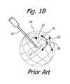
- FIGS. 1A, 1 B, and 1 Cdiagram the basic operational characteristics of the prior art.
- FIG. 2is an illustration of a complete endoscopic operating system according to the preferred embodiment of the invention.
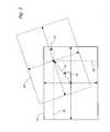
- FIG. 3is a diagram showing the view-frame mode of operation according to the preferred embodiment of the invention.
- FIG. 4is an illustration of an arbitrary coordinate system as defined by the free-frame mode of operation according to the preferred embodiment of the invention.
- FIG. 5is shows a displayed output from the endoscopic operating system according to the preferred embodiment of the invention.
- FIGS. 6A and 6Bare flow charts illustrating the operation of the central control unit according to two embodiments of the invention.
- FIG. 1Ais a diagram of a basic variable direction of view endoscope 10 .
- Such an endoscopetypically has a view vector 12 with at least two degrees of freedom 14 , 16 .
- the first degree of freedom 14permits rotation of the view vector 12 about the longitudinal axis of the endoscope 20 , which allows the view vector 12 to scan in a latitudinal direction 22 .
- the second degree of freedom 16permits rotation of the view vector 12 about an axis 24 perpendicular to the longitudinal axis 20 , which allows the view vector 12 to scan in a longitudinal direction 26 .
- These degrees of freedomdefine a natural endoscope coordinate system 28 as shown in FIG. 1 B.
- a third degree of freedom 18may also be available because it is usually possible to adjust the rotational orientation of the endoscopic view 30 . This is frequently accomplished by simply rotating an imaging device, such a camera, which is coupled to the proximal end of the endoscope. View rotation may also be provided using a prism built into the endoscope or by digitally rotating the image before viewing. Regardless of the method used, the view vector 12 is considered the axis of rotation for the view 30 .
- a usertypically controls the view by adjusting the first degree of freedom 14 and second degree of freedom 16 to select a desired direction for the view vector 12 .
- the axesmay be adjusted separately or at the same time. Once the desired direction has been obtained, the rotational orientation of the resulting image is adjusted as desired. However, because each adjustment axis is controlled independently, scanning along an arbitrary path 32 that does not line up with either of the principal scanning directions 22 , 26 is not easily accomplished. This discrepancy is demonstrated in FIG. 1C which depicts a typical path 34 traced by the view vector 12 of a traditional variable direction of view endoscope 10 while attempting to achieve the desired scan path 32 .
- a variable direction of view endoscope 10similar to the one shown in FIG. 1A, is positioned with its distal end portion 36 in a cavity to be examined 38 .
- the endoscopeis equipped with small motors (not shown) that enable electronic control of each degree of freedom of the endoscope, and encoders (not shown) that provide information about of the current orientation of the view about each respective axis.
- the motors and encoderspermit each axis to be parameterized as a variable with a value ranging from ⁇ 180 degrees to +180 degrees.
- the following variablesare provided in the interface system for storing the encoder values corresponding to the current endoscope configuration:
- ⁇ Cthe angle of the view vector about the longitudinal axis of the endoscope (first degree of freedom).
- ⁇ Cthe angle of the view vector about the axis perpendicular to the longitudinal axis (second degree of freedom).
- ⁇ Cthe angle of the arbitrary rotational orientation of the view (third degree of freedom).
- a three-axis joystick 40gives a user right/left, up/down, and counter-clockwise/clockwise input capabilities. These inputs can be stored as +/ ⁇ X, +/ ⁇ Y, and +/ ⁇ Z, respectively.
- a keypad 42facilitates additional input.
- the inputis received by a central control unit 44 .
- the central control unit 44a computer in the preferred embodiment, processes input from the user and information from the endoscope encoders to establish an appropriate adjustment for each axis.
- the appropriate adjustmentis based on a control coordinate system and may be dependent upon previous inputs, adjustments, and endoscope configurations.
- the following variablesare provided in the interface system for storing the encoder values corresponding to the desired endoscope configuration:
- ⁇ Dthe desired angle of the view vector about the longitudinal axis of the endoscope (first degree of freedom).
- ⁇ Dthe desired angle of the view vector about the axis perpendicular to the longitudinal axis (second degree of freedom).
- ⁇ Dthe desired angle of the arbitrary rotational orientation of the view (third degree of freedom).
- the adjustment informationis provided to a motor control unit 46 as ⁇ D , ⁇ D , and ⁇ D .
- the motor control unit 46controls the endoscope configuration through the motors in the endoscope 10 . Specifically, the motor control unit 46 adjusts the endoscope until ⁇ C , ⁇ C , and ⁇ C are equal to ⁇ D , ⁇ D , and ⁇ D .
- the interface systemis ready for another input. By making numerous small adjustments in rapid succession, the user is given the impression of smooth, continuous adjustment.
- An image acquisition unit 48receives image signals from the endoscope 10 and adjusts the signals as needed.
- the central control unit 44receives the adjusted signals from the image acquisition unit 48 .
- An endoscopic video image and additional relevant informationare relayed to a video display device 50 for presentation to the user. Illumination for the cavity 38 is delivered through the endoscope 10 from a standard light source 52 via a standard light guide 54 .
- a first mode of operationcan be thought of as an endoscope-frame mode.
- the control coordinate systemis equivalent to the natural coordinate system of the endoscope.
- Inputs from the userare directly applied to the endoscope configuration.
- the X value from the joystickis added to ⁇ C to provide ⁇ D .
- the Y value from the joystickis added to ⁇ C to provide ⁇ D .
- the Z value from the joystickis added to ⁇ C to provide ⁇ D .
- Endoscope-frame modeis very similar to the standard operation of a variable direction of view endoscope. Although operation of the endoscope is still limited to the natural coordinate system of the endoscope, easily specified compound adjustments can be precisely carried out by the interface system. However, in this mode it may still be difficult for a user to determine his or her desired adjustment as the orientation of each axis of motion is not constant relative to the endoscopic view.
- a second mode of operationwhich can be thought of as view-frame mode, addresses this issue.
- the control coordinate system for specifying adjustmentis aligned with the center of the current view 56 .
- the view-frame mode control coordinate systemalways moves with the view.
- the userspecifies a desired view 58 based on the way in which the current view 56 appears on the screen. Through control of the joystick, the user may choose a direction and speed to move the center of the view and a rotation for the rotational view orientation.
- the interfacedetermines the best way to adjust the endoscope to achieve the desired view 58 .
- View-frame modeis ideal for making small adjustments to the current view.
- joystick inputsIn controlling view-frame mode, joystick inputs must be converted to comprise a direction angle 60 , a step distance angle 62 , and a view rotation angle 64 .
- the following variablesare provided in the interface system for storing these angle values:
- ⁇ Vstores the angle of the direction selected 60 .
- ⁇ Vstores the angle of the step distance selected 62 .
- ⁇ Vstores the view rotation angle selected 64 minus the direction angle selected 60 .
- FIG. 3shows how the joystick inputs are interpreted during view-frame operation.
- An X value 66 and a Y value 68 from the joysticktogether describe a center for the desired view 58 .
- An inverse tangent functionis used to calculate a value for ⁇ V .
- the Pythagorean Theoremis used to calculate a distance which is then converted into a value for ⁇ V .
- the Z value from the joystickis the desired view rotation angle 64 .
- Rotation matricesare used by the central control unit 44 to calculate the desired endoscope configuration in the preferred embodiment of view-frame mode.
- the variables ⁇ V , ⁇ V , and ⁇ Vare used in the rotation matrix of Equation 1, which describes the orientation of the desired view relative to the current view.
- R ⁇ ( ⁇ V , ⁇ V , ⁇ V )[ cos ⁇ ⁇ ⁇ V - sin ⁇ ⁇ ⁇ V 0 sin ⁇ ⁇ ⁇ V cos ⁇ ⁇ ⁇ V 0 0 0 1 ] ⁇ [ cos ⁇ ⁇ ⁇ V 0 sin ⁇ ⁇ ⁇ V 0 1 0 - sin ⁇ ⁇ ⁇ V 0 cos ⁇ ⁇ ⁇ V ] ⁇ ⁇ [ cos ⁇ ⁇ ⁇ V - sin ⁇ ⁇ ⁇ V 0 sin ⁇ ⁇ ⁇ V cos ⁇ ⁇ 0 0 0 1 ] Equation ⁇ ⁇ 1
- Equation 2The variables ⁇ C , ⁇ C , and ⁇ C are used in the rotation matrix of Equation 2, which describes the orientation of the current view relative to the default position of the endoscope.
- R ⁇ ( ⁇ C , ⁇ C , ⁇ C )[ cos ⁇ ⁇ ⁇ C - sin ⁇ ⁇ ⁇ C 0 sin ⁇ ⁇ ⁇ C cos ⁇ ⁇ ⁇ C 0 0 0 1 ] ⁇ [ cos ⁇ ⁇ ⁇ C 0 sin ⁇ ⁇ ⁇ C 0 1 0 - sin ⁇ ⁇ ⁇ C 0 cos ⁇ ⁇ ⁇ C ] ⁇ ⁇ [ cos ⁇ ⁇ ⁇ C - sin ⁇ ⁇ ⁇ C 0 sin ⁇ ⁇ ⁇ C cos ⁇ ⁇ ⁇ C 0 0 0 1 ] Equation ⁇ ⁇ 2
- the rotation matrix of Equation 3describes the orientation of the desired view relative to the default position of the endoscope.
- R ( ⁇ D , ⁇ D , ⁇ D )R ( ⁇ C , ⁇ C , ⁇ C ) ⁇ R ( ⁇ V , ⁇ V , ⁇ V ) Equation 3
- the rotation matrix of Equation 3can also be expressed as the rotation matrix of Equation 4, containing the desired endoscope configuration variables, ⁇ D , ⁇ D , and ⁇ D .
- R ⁇ ( ⁇ D , ⁇ D , ⁇ D )[ cos ⁇ ⁇ ⁇ D - sin ⁇ ⁇ ⁇ D 0 sin ⁇ ⁇ ⁇ D cos ⁇ ⁇ ⁇ D 0 0 0 1 ] ⁇ [ cos ⁇ ⁇ ⁇ D 0 sin ⁇ ⁇ ⁇ D 0 1 0 - sin ⁇ ⁇ ⁇ D 0 cos ⁇ ⁇ ⁇ D ] ⁇ ⁇ [ cos ⁇ ⁇ ⁇ D - sin ⁇ ⁇ ⁇ D 0 sin ⁇ ⁇ ⁇ D cos ⁇ ⁇ ⁇ D 0 0 0 1 ] Equation ⁇ ⁇ 4
- the rotation matrices of Equations 1-4complete a transformation of the desired view coordinates from the current view coordinate system reference frame into the natural endoscope coordinate system reference frame.
- the control coordinate system for specifying adjustmentis aligned with an arbitrary coordinate system 70 defined within a cavity 38 .
- the arbitrary coordinate system 70may be aligned with gravity or with a particularly notable feature, and may be created automatically or based on a user's instructions.
- the usermay specify an orientation for an arbitrary coordinate system by selecting a direction to correspond with a pole of that arbitrary coordinate system.
- a coordinate systemcould be defined based on the output of an accelerometer responsive to gravity.
- the following variablesare provided in the interface system for storing the orientation of an arbitrary coordinate system 70 :
- ⁇ Fstores the encoder value describing the angle of the view vector about the longitudinal axis of the endoscope when the view is aligned at a pole of the arbitrary coordinate system 72 .
- ⁇ Fstores the encoder value describing the angle of the view vector about the axis perpendicular to the longitudinal axis when the view is aligned at the pole of the arbitrary coordinate system 72 .
- ⁇ Fstores the encoder value describing the angle of the arbitrary rotational orientation of the view when the view is aligned at the pole of the arbitrary coordinate system 72 .
- the viewis defined and specified with respect to the arbitrary coordinate system.
- the following variablesare provided in the interface system for storing the orientation of the view in an arbitrary coordinate system:
- ⁇ Fstores the longitude value of the view vector in the arbitrary coordinate system.
- ⁇ Fstores the latitude value of the view vector in the arbitrary coordinate system.
- ⁇ Fstores the angle of the arbitrary rotational orientation of the view in the arbitrary coordinate system.
- Inputs from the userare directly applied to the orientation of the view within the arbitrary coordinate system.
- the X value from the joystickis used to increment ⁇ F .
- the Y value from the joystickis used to increment ⁇ F .
- the Z value from the joystickmay be used to increment ⁇ F .
- ⁇ Fis usually held constant in free-frame mode to simplify the use of the arbitrary coordinate system.
- Rotation matricesare used by the central control unit 44 to calculate the desired endoscope configuration in the preferred embodiment of free-frame mode.
- the variables ⁇ F , ⁇ F , and ⁇ Fare used in Equation 5, which describes the orientation of the arbitrary coordinate system relative to the default position of the endoscope.
- R ⁇ ( ⁇ F , ⁇ F , ⁇ F )[ cos ⁇ ⁇ ⁇ F - sin ⁇ ⁇ ⁇ F 0 sin ⁇ ⁇ ⁇ F cos ⁇ ⁇ ⁇ F 0 0 0 1 ] ⁇ [ cos ⁇ ⁇ ⁇ F 0 sin ⁇ ⁇ ⁇ F 0 1 0 - sin ⁇ ⁇ ⁇ F 0 cos ⁇ ⁇ ⁇ F ] ⁇ ⁇ [ cos ⁇ ⁇ ⁇ F - sin ⁇ ⁇ ⁇ F 0 sin ⁇ ⁇ ⁇ F cos ⁇ ⁇ 0 0 0 1 ] Equation ⁇ ⁇ 5
- Equation 6The variables ⁇ F , ⁇ F , and ⁇ F are used in Equation 6, which describes the orientation of the desired view within the arbitrary coordinate system.
- R ⁇ ( ⁇ F , ⁇ F , ⁇ F )[ cos ⁇ ⁇ ⁇ F - sin ⁇ ⁇ ⁇ F 0 sin ⁇ ⁇ ⁇ F cos ⁇ ⁇ ⁇ F 0 0 0 1 ] ⁇ [ cos ⁇ ⁇ ⁇ F 0 sin ⁇ ⁇ ⁇ F 0 1 0 - sin ⁇ ⁇ F 0 cos ⁇ ⁇ ⁇ F ] ⁇ ⁇ [ cos ⁇ ⁇ ⁇ F - sin ⁇ ⁇ ⁇ F 0 sin ⁇ ⁇ ⁇ F cos ⁇ ⁇ ⁇ F 0 0 0 1 ] Equation ⁇ ⁇ 6
- the rotation matrix of Equation 7describes the orientation of the desired view relative to the default position of the endoscope.
- R ( ⁇ D , ⁇ D , ⁇ D )R ( ⁇ F , ⁇ F , ⁇ F ) ⁇ R ( ⁇ F , ⁇ F , ⁇ F ) Equation 7
- the rotation matrix of Equation 7can also be expressed as the rotation matrix of Equation 8, containing the desired endoscope configuration variables ⁇ D , ⁇ D , and ⁇ D .
- R ⁇ ( ⁇ D , ⁇ D , ⁇ D )[ cos ⁇ ⁇ ⁇ D - sin ⁇ ⁇ ⁇ D 0 sin ⁇ ⁇ ⁇ D cos ⁇ ⁇ ⁇ D 0 0 0 1 ] ⁇ [ cos ⁇ ⁇ ⁇ D 0 sin ⁇ ⁇ ⁇ D 0 1 0 - sin ⁇ ⁇ ⁇ D 0 cos ⁇ ⁇ ⁇ D ] ⁇ ⁇ [ cos ⁇ ⁇ ⁇ D - sin ⁇ ⁇ ⁇ D 0 sin ⁇ ⁇ ⁇ D cos ⁇ ⁇ ⁇ D 0 0 0 1 ] Equation ⁇ ⁇ 8
- the rotation matrices of Equations 5-8complete a transformation of the desired view coordinate from the arbitrary coordinate system reference frame into the natural endoscope coordinate system reference frame.
- Additional sets of free-frame variables in the interface systemenable the user to store multiple arbitrary coordinate systems. These coordinate systems may be configured independently, each based on a different set of preferences.
- the current view values for ⁇ F , ⁇ F , and ⁇ Fare determined for the desired arbitrary coordinate system before that arbitrary coordinate system is used.
- the rotation matrix of Equation 9an inverse of the rotation matrix of Equation 5, is needed to calculate ⁇ F , ⁇ F , and ⁇ F .
- the rotation matrix of Equation 10describes the orientation of the view within the arbitrary coordinate system.
- R ( ⁇ F , ⁇ F , ⁇ F )R ⁇ 1 ( ⁇ F , ⁇ F , ⁇ F ) ⁇ R ( ⁇ C , ⁇ C , ⁇ C ) Equation 10
- the rotation matrix of Equation 10can also be expressed as the rotation matrix of Equation 11, containing the view orientation variables ⁇ F , ⁇ F , and ⁇ F .
- R ⁇ ( ⁇ F , ⁇ F , ⁇ F )[ cos ⁇ ⁇ ⁇ F - sin ⁇ ⁇ ⁇ F 0 sin ⁇ ⁇ ⁇ F cos ⁇ ⁇ ⁇ F 0 0 0 1 ] ⁇ ⁇ ⁇ [ cos ⁇ ⁇ ⁇ F 0 sin ⁇ ⁇ ⁇ F 0 1 0 - sin ⁇ ⁇ ⁇ F 0 cos ⁇ ⁇ ⁇ F ] ⁇ [ cos ⁇ ⁇ ⁇ F - sin ⁇ ⁇ ⁇ F 0 sin ⁇ ⁇ ⁇ F cos ⁇ ⁇ ⁇ F 0 0 0 1 ] Equation ⁇ ⁇ 11
- the rotation matrices of Equations 9-11complete a transformation of the current view coordinate from the natural endoscope coordinate system reference frame into the arbitrary coordinate system reference frame.
- Memoryis provided in the interface system for storing multiple sets of encoder variables.
- Each of the sets of encoder variablesis a stored endoscope configuration.
- Each of the stored endoscope configurationscorresponds to a view.
- the stored endoscope configurationsenable the user to return to a previous view.
- FIG. 5illustrates an embodiment of this presentation.
- the screen of the display device 74is organized into multiple sections, each with a different purpose.
- a large section of the screen 74is used to display a video image 76 from the endoscope.
- a representation of a coordinate system 77may be graphically superimposed on the video image 76 to aid the user in understanding and using that coordinate system.
- Several smaller captured images 78are provided, each one corresponding to a stored endoscope configuration.
- the captured images 78act in place of names to allow a user to easily identify each stored endoscope configuration.
- a computer generated depiction of the endoscope 80is provided to assist the user in understanding the current view 30 .
- the depiction 80shows the endoscope 10 and the current view 30 from a viewpoint outside of the cavity.
- One or more coordinate systems 81may also be shown in this depiction 80 .
- the depiction 80may include simulated important features or other markings (not shown) to aid the situational understanding of the user. For example, a tumor to be removed, as located in a preoperative scan, could be shown in the depiction 80 to aid a surgeon in locating and identifying the tumor visually.
- the current mode and display settings 82are displayed.
- the information discussed abovemay be displayed on multiple display devices. For example, the endoscopic image might be displayed separately from the other endoscopic operating system information.
- FIG. 6Ais a flow chart illustrating the operation of the central control unit 44 , shown in FIG. 2, according to an embodiment of the invention.
- the central control unit 44waits for a signal indicating user input 84 . If it receives a joystick input 86 , it prepares to perform the view adjustment desired by the user. The first step in achieving this adjustment is to identify the current operating mode of the interface system 88 . The next step is to calculate values for the desired endoscope configuration variables ⁇ D , ⁇ D , and ⁇ D in a manner corresponding to the current operating mode 90 , 92 , 94 as described above. These values are then sent to the motor controller unit 46 , which appropriately moves the motors 96 . Once this move has been completed, the interface system resets and waits for another input 84 .
- the central control unit 44receives a button input 98 , it first identifies the type of button pressed 100 . If the user has chosen to set a new mode 102 , the mode is changed and the adjustment sequence is started 104 . If the user has selected a stored endoscope configuration 106 , the interface system instructs the endoscope to adjust directly to that endoscope configuration 96 . If the user has elected to save the current endoscope configuration 108 , the current endoscope configuration variables and current image are stored in memory before the interface system resets and waits for another input 84 . If the user has chosen to adjust the interface settings 110 , the appropriate adjustment is made, and the interface system resets and waits for another input 84 .
- Endoscope-frame modecan be simulated in free-frame mode by utilizing a coordinate system aligned with the natural coordinate system of the endoscope. This eliminates the need for a separate calculation method for endoscope-frame mode.
- View-frame mode and free-frame modeboth involve a similar matrix multiplication.
- the programcan therefore be simplified by combining the three modes into a single calculation module 112 .
- values appropriate for the current modeare first assigned to variables 114 .
- a generic matrix computation 116can then be used to solve for the desired encoder values.
- the present inventionprovides an interface for a variable direction of view endoscope that is easy to use and capable of adjusting multiple degrees of freedom of the endoscope simultaneously and precisely according to the desires of the user.
- the present inventionhas been described above in terms of a presently preferred embodiment so that an understanding of the present invention can be conveyed.
- an interface for a variable direction of view endoscope and methods of operationnot specifically described herein but with which the present invention is applicable.
- the display features of the preferred embodiment of the present inventioncould be used in a system that does not control the endoscope.
- specific formulaswere given for an endoscope of the type shown in FIG. 1, the interface of the present invention could be applied to any type of variable direction of view endoscope when provided with calculation functions consistent with the operation of the endoscope selected.
- Some endoscope variationswould utilize electronic processing and memory instead of motors and encoders to accomplish view adjustments.
Landscapes
- Life Sciences & Earth Sciences (AREA)
- Health & Medical Sciences (AREA)
- Surgery (AREA)
- Engineering & Computer Science (AREA)
- Biophysics (AREA)
- Medical Informatics (AREA)
- Nuclear Medicine, Radiotherapy & Molecular Imaging (AREA)
- Optics & Photonics (AREA)
- Pathology (AREA)
- Radiology & Medical Imaging (AREA)
- Veterinary Medicine (AREA)
- Biomedical Technology (AREA)
- Heart & Thoracic Surgery (AREA)
- Physics & Mathematics (AREA)
- Molecular Biology (AREA)
- Animal Behavior & Ethology (AREA)
- General Health & Medical Sciences (AREA)
- Public Health (AREA)
- Mechanical Engineering (AREA)
- Endoscopes (AREA)
- Instruments For Viewing The Inside Of Hollow Bodies (AREA)
Abstract
Description


Claims (25)
Priority Applications (5)
| Application Number | Priority Date | Filing Date | Title |
|---|---|---|---|
| US10/020,374US6663559B2 (en) | 2001-12-14 | 2001-12-14 | Interface for a variable direction of view endoscope |
| JP2003552114AJP4460297B2 (en) | 2001-12-14 | 2002-12-09 | Directional view end scope interface |
| PCT/US2002/039298WO2003051176A2 (en) | 2001-12-14 | 2002-12-09 | Interface for a variable direction of view endoscope |
| AU2002360526AAU2002360526A1 (en) | 2001-12-14 | 2002-12-09 | Interface for a variable direction of view endoscope |
| US10/734,688US7052455B2 (en) | 2001-12-14 | 2003-12-12 | Interface for a variable direction-of-view endoscope |
Applications Claiming Priority (1)
| Application Number | Priority Date | Filing Date | Title |
|---|---|---|---|
| US10/020,374US6663559B2 (en) | 2001-12-14 | 2001-12-14 | Interface for a variable direction of view endoscope |
Related Child Applications (1)
| Application Number | Title | Priority Date | Filing Date |
|---|---|---|---|
| US10/734,688Continuation-In-PartUS7052455B2 (en) | 2001-12-14 | 2003-12-12 | Interface for a variable direction-of-view endoscope |
Publications (2)
| Publication Number | Publication Date |
|---|---|
| US20030114730A1 US20030114730A1 (en) | 2003-06-19 |
| US6663559B2true US6663559B2 (en) | 2003-12-16 |
Family
ID=21798286
Family Applications (2)
| Application Number | Title | Priority Date | Filing Date |
|---|---|---|---|
| US10/020,374Expired - LifetimeUS6663559B2 (en) | 2001-12-14 | 2001-12-14 | Interface for a variable direction of view endoscope |
| US10/734,688Expired - LifetimeUS7052455B2 (en) | 2001-12-14 | 2003-12-12 | Interface for a variable direction-of-view endoscope |
Family Applications After (1)
| Application Number | Title | Priority Date | Filing Date |
|---|---|---|---|
| US10/734,688Expired - LifetimeUS7052455B2 (en) | 2001-12-14 | 2003-12-12 | Interface for a variable direction-of-view endoscope |
Country Status (4)
| Country | Link |
|---|---|
| US (2) | US6663559B2 (en) |
| JP (1) | JP4460297B2 (en) |
| AU (1) | AU2002360526A1 (en) |
| WO (1) | WO2003051176A2 (en) |
Cited By (29)
| Publication number | Priority date | Publication date | Assignee | Title |
|---|---|---|---|---|
| US20030163591A1 (en)* | 2002-02-26 | 2003-08-28 | Loda David C. | Remote tablet-based internet inspection system |
| US20050054895A1 (en)* | 2003-09-09 | 2005-03-10 | Hoeg Hans David | Method for using variable direction of view endoscopy in conjunction with image guided surgical systems |
| US20050113643A1 (en)* | 2003-11-20 | 2005-05-26 | Hale Eric L. | Method and apparatus for displaying endoscopic images |
| US20050177026A1 (en)* | 2004-02-09 | 2005-08-11 | Hoeg Hans D. | Endoscope with variable direction of view module |
| US20050179374A1 (en)* | 2004-02-14 | 2005-08-18 | Won-Kyu Kwak | Organic electro-luminescent display device and method of manufacturing the same |
| US20050187432A1 (en)* | 2004-02-20 | 2005-08-25 | Eric Lawrence Hale | Global endoscopic viewing indicator |
| US20060015012A1 (en)* | 2004-07-14 | 2006-01-19 | Saichi Sato | Endoscope device |
| US20060074289A1 (en)* | 2004-08-26 | 2006-04-06 | Doron Adler | Wireless determination of endoscope orientation |
| EP1685791A1 (en) | 2005-01-26 | 2006-08-02 | Karl Storz Development Corp. | Illumination system for variable direction of view instruments |
| US20060189842A1 (en)* | 2005-02-14 | 2006-08-24 | Hoeg Hans D | Method for using variable direction of view endoscopy in conjunction with image guided surgical systems |
| US20060206006A1 (en)* | 2005-02-14 | 2006-09-14 | Schara Nathan J | Variable direction of view instrument with on-board actuators |
| US20080161642A1 (en)* | 2003-04-21 | 2008-07-03 | Eric Lawrence Hale | Method For Capturing And Displaying Endoscopic Maps |
| US7427263B2 (en) | 2004-03-03 | 2008-09-23 | Karl Storz Development Corp. | Method and interface for operating a variable direction of view endoscope |
| US20090248042A1 (en)* | 2008-03-27 | 2009-10-01 | Kirschenman Mark B | Model catheter input device |
| US20100010301A1 (en)* | 2008-07-08 | 2010-01-14 | Hale Eric L | Solid State Variable Direction of View Endoscope |
| US20120116158A1 (en)* | 2008-07-08 | 2012-05-10 | Hale Eric L | Wide Angle Flexible Endoscope |
| US20140012081A1 (en)* | 2011-03-08 | 2014-01-09 | Olympus Winter & Ibe Gmbh | Method and system for displaying video-endoscopic image data of a video endoscope |
| US8758234B2 (en) | 2008-07-08 | 2014-06-24 | Karl Storz Imaging, Inc. | Solid state variable direction of view endoscope |
| US9033871B2 (en) | 2004-04-07 | 2015-05-19 | Karl Storz Imaging, Inc. | Gravity referenced endoscopic image orientation |
| EP2696571A3 (en)* | 2012-08-10 | 2016-01-06 | Karl Storz Imaging Inc. | Deployable imaging system equipped with solid state imager |
| US9668768B2 (en) | 2013-03-15 | 2017-06-06 | Synaptive Medical (Barbados) Inc. | Intelligent positioning system and methods therefore |
| US10092169B2 (en) | 2008-07-08 | 2018-10-09 | Karl Storz Imaging, Inc. | Solid state variable direction of view endoscope |
| US10231788B2 (en) | 2008-03-27 | 2019-03-19 | St. Jude Medical, Atrial Fibrillation Division, Inc. | Robotic catheter system |
| US10433763B2 (en) | 2013-03-15 | 2019-10-08 | Synaptive Medical (Barbados) Inc. | Systems and methods for navigation and simulation of minimally invasive therapy |
| CN110325331A (en)* | 2017-02-28 | 2019-10-11 | 索尼公司 | Therapeutic support arm system and control device |
| US10744646B2 (en) | 2013-08-29 | 2020-08-18 | Wayne State University | Camera control system and method |
| US11039085B2 (en) | 2019-10-28 | 2021-06-15 | Karl Storz Imaging, Inc. | Video camera having video image orientation based on vector information |
| US11070745B2 (en) | 2019-10-28 | 2021-07-20 | Karl Storz Imaging, Inc. | Automatic image orientation based on use |
| US12396621B2 (en) | 2021-12-14 | 2025-08-26 | Karl Storz Imaging, Inc. | Frame processing of imaging scope data for user interface presentation |
Families Citing this family (54)
| Publication number | Priority date | Publication date | Assignee | Title |
|---|---|---|---|---|
| US8944070B2 (en) | 1999-04-07 | 2015-02-03 | Intuitive Surgical Operations, Inc. | Non-force reflecting method for providing tool force information to a user of a telesurgical system |
| US8066634B2 (en)* | 2003-07-28 | 2011-11-29 | Welch Allyn, Inc. | Digital otoscope |
| JP4695420B2 (en)* | 2004-09-27 | 2011-06-08 | オリンパス株式会社 | Bending control device |
| US7517314B2 (en)* | 2004-10-14 | 2009-04-14 | Karl Storz Development Corp. | Endoscopic imaging with indication of gravity direction |
| KR100681233B1 (en)* | 2004-10-28 | 2007-02-09 | 김재황 | Laparoscopic Surgery Monitor and Display Method |
| US7811224B2 (en) | 2004-11-09 | 2010-10-12 | Karl Storz Development Corp. | Method for dealing with singularities in gravity referenced endoscopic imaging |
| US7221522B2 (en)* | 2005-01-28 | 2007-05-22 | Karl Storz Development Corp. | Optical system for variable direction of view instrument |
| US9789608B2 (en) | 2006-06-29 | 2017-10-17 | Intuitive Surgical Operations, Inc. | Synthetic representation of a surgical robot |
| WO2007080783A1 (en)* | 2006-01-13 | 2007-07-19 | Olympus Medical Systems Corp. | Rotary self-running endoscope system, program, and method of driving rotary self-running endoscope system |
| US8016749B2 (en) | 2006-03-21 | 2011-09-13 | Boston Scientific Scimed, Inc. | Vision catheter having electromechanical navigation |
| JP4607043B2 (en)* | 2006-04-05 | 2011-01-05 | カール・ストーツ・デベロップメント・コーポレーション | Endoscopic image forming method with display of gravity direction |
| DE602006015913D1 (en)* | 2006-04-10 | 2010-09-16 | Storz Karl Dev Corp | Endoscopic imaging with indication of the direction of gravity |
| KR101477133B1 (en) | 2006-06-13 | 2014-12-29 | 인튜어티브 서지컬 인코포레이티드 | Minimally invasive surgical system |
| US20090192523A1 (en) | 2006-06-29 | 2009-07-30 | Intuitive Surgical, Inc. | Synthetic representation of a surgical instrument |
| US10258425B2 (en) | 2008-06-27 | 2019-04-16 | Intuitive Surgical Operations, Inc. | Medical robotic system providing an auxiliary view of articulatable instruments extending out of a distal end of an entry guide |
| US12357400B2 (en) | 2006-06-29 | 2025-07-15 | Intuitive Surgical Operations, Inc. | Synthetic representation of a surgical robot |
| US10008017B2 (en) | 2006-06-29 | 2018-06-26 | Intuitive Surgical Operations, Inc. | Rendering tool information as graphic overlays on displayed images of tools |
| US9718190B2 (en) | 2006-06-29 | 2017-08-01 | Intuitive Surgical Operations, Inc. | Tool position and identification indicator displayed in a boundary area of a computer display screen |
| US8292801B2 (en)* | 2006-12-22 | 2012-10-23 | Olympus Medical Systems Corp. | Surgical treatment apparatus |
| US8620473B2 (en) | 2007-06-13 | 2013-12-31 | Intuitive Surgical Operations, Inc. | Medical robotic system with coupled control modes |
| US8903546B2 (en) | 2009-08-15 | 2014-12-02 | Intuitive Surgical Operations, Inc. | Smooth control of an articulated instrument across areas with different work space conditions |
| US9469034B2 (en) | 2007-06-13 | 2016-10-18 | Intuitive Surgical Operations, Inc. | Method and system for switching modes of a robotic system |
| US9084623B2 (en) | 2009-08-15 | 2015-07-21 | Intuitive Surgical Operations, Inc. | Controller assisted reconfiguration of an articulated instrument during movement into and out of an entry guide |
| US9138129B2 (en) | 2007-06-13 | 2015-09-22 | Intuitive Surgical Operations, Inc. | Method and system for moving a plurality of articulated instruments in tandem back towards an entry guide |
| US9089256B2 (en)* | 2008-06-27 | 2015-07-28 | Intuitive Surgical Operations, Inc. | Medical robotic system providing an auxiliary view including range of motion limitations for articulatable instruments extending out of a distal end of an entry guide |
| US12239396B2 (en) | 2008-06-27 | 2025-03-04 | Intuitive Surgical Operations, Inc. | Medical robotic system providing an auxiliary view including range of motion limitations for articulatable instruments extending out of a distal end of an entry guide |
| US8864652B2 (en)* | 2008-06-27 | 2014-10-21 | Intuitive Surgical Operations, Inc. | Medical robotic system providing computer generated auxiliary views of a camera instrument for controlling the positioning and orienting of its tip |
| DE102008057734B4 (en)* | 2008-11-17 | 2016-07-28 | Digital Endoscopy Gmbh | Videoscope |
| DE102009010263B4 (en)* | 2009-02-24 | 2011-01-20 | Reiner Kunz | Method for navigating an endoscopic instrument during technical endoscopy and associated device |
| KR101903307B1 (en)* | 2009-03-26 | 2018-10-01 | 인튜어티브 서지컬 오퍼레이션즈 인코포레이티드 | System for providing visual guidance for steering a tip of an endoscopic device towards one or more landmarks and assisting an operator in endoscopic navigation |
| US10004387B2 (en)* | 2009-03-26 | 2018-06-26 | Intuitive Surgical Operations, Inc. | Method and system for assisting an operator in endoscopic navigation |
| US8337397B2 (en) | 2009-03-26 | 2012-12-25 | Intuitive Surgical Operations, Inc. | Method and system for providing visual guidance to an operator for steering a tip of an endoscopic device toward one or more landmarks in a patient |
| US12266040B2 (en) | 2009-03-31 | 2025-04-01 | Intuitive Surgical Operations, Inc. | Rendering tool information as graphic overlays on displayed images of tools |
| US8918211B2 (en) | 2010-02-12 | 2014-12-23 | Intuitive Surgical Operations, Inc. | Medical robotic system providing sensory feedback indicating a difference between a commanded state and a preferred pose of an articulated instrument |
| US9492927B2 (en) | 2009-08-15 | 2016-11-15 | Intuitive Surgical Operations, Inc. | Application of force feedback on an input device to urge its operator to command an articulated instrument to a preferred pose |
| US20110190580A1 (en)* | 2009-09-28 | 2011-08-04 | Bennett James D | Analysis engine within a network supporting intravaginal monitoring |
| JP5944395B2 (en) | 2010-10-08 | 2016-07-05 | コーニンクレッカ フィリップス エヌ ヴェKoninklijke Philips N.V. | Flexible tether with integrated sensor for dynamic instrument tracking |
| US10674968B2 (en) | 2011-02-10 | 2020-06-09 | Karl Storz Imaging, Inc. | Adjustable overlay patterns for medical display |
| US11412998B2 (en) | 2011-02-10 | 2022-08-16 | Karl Storz Imaging, Inc. | Multi-source medical display |
| US10631712B2 (en)* | 2011-02-10 | 2020-04-28 | Karl Storz Imaging, Inc. | Surgeon's aid for medical display |
| JP5977497B2 (en)* | 2011-09-22 | 2016-08-24 | オリンパス株式会社 | Endoscope apparatus, operation method and program |
| US9763563B2 (en) | 2012-07-11 | 2017-09-19 | Karl Storz Imaging, Inc. | Endoscopic camera single-button mode activation |
| JP6375309B2 (en) | 2013-02-01 | 2018-08-15 | デカ・プロダクツ・リミテッド・パートナーシップ | Endoscope with camera capable of panning |
| US10616491B2 (en) | 2013-02-01 | 2020-04-07 | Deka Products Limited Partnership | Endoscope with pannable camera and related method |
| US10507066B2 (en) | 2013-02-15 | 2019-12-17 | Intuitive Surgical Operations, Inc. | Providing information of tools by filtering image areas adjacent to or on displayed images of the tools |
| US11188285B2 (en)* | 2014-07-02 | 2021-11-30 | Covidien Lp | Intelligent display |
| US11612306B2 (en)* | 2017-11-01 | 2023-03-28 | Sony Corporation | Surgical arm system and surgical arm control system |
| WO2019210227A1 (en) | 2018-04-26 | 2019-10-31 | Deka Products Limited Partnership | Endoscope with rotatable camera and related methods |
| US11202014B2 (en) | 2018-07-06 | 2021-12-14 | Medos International Sari | Camera scope electronic variable angle of view |
| US11032481B2 (en) | 2018-07-06 | 2021-06-08 | Medos International Sarl | Camera scope electronic variable prism |
| DE102019007290A1 (en)* | 2019-10-21 | 2021-04-22 | Karl Storz Se & Co. Kg | Sensor-based surgery set and procedure |
| US11900590B2 (en)* | 2020-10-21 | 2024-02-13 | Baker Hughes Holdings Llc | Inspection device articulation transformation based on image transformation |
| US12070196B2 (en) | 2020-11-23 | 2024-08-27 | Medos International Sarl | Arthroscopic medical implements and assemblies |
| EP4169469A1 (en) | 2021-10-25 | 2023-04-26 | Erbe Vision GmbH | Laparoskopic camera arrangement and method for camera alignment error correction |
Citations (9)
| Publication number | Priority date | Publication date | Assignee | Title |
|---|---|---|---|---|
| US4697577A (en)* | 1986-05-22 | 1987-10-06 | Baxter Travenol Laboratories, Inc. | Scanning microtelescope for surgical applications |
| US5313306A (en) | 1991-05-13 | 1994-05-17 | Telerobotics International, Inc. | Omniview motionless camera endoscopy system |
| US5524180A (en) | 1992-08-10 | 1996-06-04 | Computer Motion, Inc. | Automated endoscope system for optimal positioning |
| US5776050A (en)* | 1995-07-24 | 1998-07-07 | Medical Media Systems | Anatomical visualization system |
| US5876325A (en)* | 1993-11-02 | 1999-03-02 | Olympus Optical Co., Ltd. | Surgical manipulation system |
| US5954634A (en) | 1997-04-11 | 1999-09-21 | Olympus Optical Co. Ltd. | Field conversion system for rigid endoscopes |
| US6097423A (en) | 1997-06-06 | 2000-08-01 | Karl Storz Imaging, Inc. | Image orientation for endoscopic video displays |
| US6371909B1 (en)* | 1998-02-19 | 2002-04-16 | California Institute Of Technology | Apparatus and method for providing spherical viewing during endoscopic procedures |
| US6428470B1 (en)* | 1995-09-15 | 2002-08-06 | Pinotage, Llc | Imaging system and components thereof |
Family Cites Families (1)
| Publication number | Priority date | Publication date | Assignee | Title |
|---|---|---|---|---|
| JP3345645B2 (en)* | 2000-06-20 | 2002-11-18 | 東京大学長 | Body cavity observation device |
- 2001
- 2001-12-14USUS10/020,374patent/US6663559B2/ennot_activeExpired - Lifetime
- 2002
- 2002-12-09JPJP2003552114Apatent/JP4460297B2/ennot_activeExpired - Fee Related
- 2002-12-09WOPCT/US2002/039298patent/WO2003051176A2/enactiveApplication Filing
- 2002-12-09AUAU2002360526Apatent/AU2002360526A1/ennot_activeAbandoned
- 2003
- 2003-12-12USUS10/734,688patent/US7052455B2/ennot_activeExpired - Lifetime
Patent Citations (10)
| Publication number | Priority date | Publication date | Assignee | Title |
|---|---|---|---|---|
| US4697577A (en)* | 1986-05-22 | 1987-10-06 | Baxter Travenol Laboratories, Inc. | Scanning microtelescope for surgical applications |
| US5313306A (en) | 1991-05-13 | 1994-05-17 | Telerobotics International, Inc. | Omniview motionless camera endoscopy system |
| US5524180A (en) | 1992-08-10 | 1996-06-04 | Computer Motion, Inc. | Automated endoscope system for optimal positioning |
| US5907664A (en) | 1992-08-10 | 1999-05-25 | Computer Motion, Inc. | Automated endoscope system for optimal positioning |
| US5876325A (en)* | 1993-11-02 | 1999-03-02 | Olympus Optical Co., Ltd. | Surgical manipulation system |
| US5776050A (en)* | 1995-07-24 | 1998-07-07 | Medical Media Systems | Anatomical visualization system |
| US6428470B1 (en)* | 1995-09-15 | 2002-08-06 | Pinotage, Llc | Imaging system and components thereof |
| US5954634A (en) | 1997-04-11 | 1999-09-21 | Olympus Optical Co. Ltd. | Field conversion system for rigid endoscopes |
| US6097423A (en) | 1997-06-06 | 2000-08-01 | Karl Storz Imaging, Inc. | Image orientation for endoscopic video displays |
| US6371909B1 (en)* | 1998-02-19 | 2002-04-16 | California Institute Of Technology | Apparatus and method for providing spherical viewing during endoscopic procedures |
Cited By (57)
| Publication number | Priority date | Publication date | Assignee | Title |
|---|---|---|---|---|
| US8082317B2 (en)* | 2002-02-26 | 2011-12-20 | United Technologies Corporation | Remote tablet-based internet inspection system |
| US20030163591A1 (en)* | 2002-02-26 | 2003-08-28 | Loda David C. | Remote tablet-based internet inspection system |
| US9603508B2 (en) | 2003-04-21 | 2017-03-28 | Karl Storz Imaging, Inc. | Method for capturing and displaying endoscopic maps |
| US20080161642A1 (en)* | 2003-04-21 | 2008-07-03 | Eric Lawrence Hale | Method For Capturing And Displaying Endoscopic Maps |
| US20050054895A1 (en)* | 2003-09-09 | 2005-03-10 | Hoeg Hans David | Method for using variable direction of view endoscopy in conjunction with image guided surgical systems |
| US20050113643A1 (en)* | 2003-11-20 | 2005-05-26 | Hale Eric L. | Method and apparatus for displaying endoscopic images |
| US7232409B2 (en) | 2003-11-20 | 2007-06-19 | Karl Storz Development Corp. | Method and apparatus for displaying endoscopic images |
| US20050177026A1 (en)* | 2004-02-09 | 2005-08-11 | Hoeg Hans D. | Endoscope with variable direction of view module |
| US9591962B2 (en) | 2004-02-09 | 2017-03-14 | Karl Storz Imaging, Inc. | Endoscope with variable direction of view module |
| US7344494B2 (en) | 2004-02-09 | 2008-03-18 | Karl Storz Development Corp. | Endoscope with variable direction of view module |
| US20080021282A1 (en)* | 2004-02-09 | 2008-01-24 | Hoeg Hans D | Endoscope With Variable Direction of View Module |
| US20050179374A1 (en)* | 2004-02-14 | 2005-08-18 | Won-Kyu Kwak | Organic electro-luminescent display device and method of manufacturing the same |
| US9615772B2 (en)* | 2004-02-20 | 2017-04-11 | Karl Storz Imaging, Inc. | Global endoscopic viewing indicator |
| US20050187432A1 (en)* | 2004-02-20 | 2005-08-25 | Eric Lawrence Hale | Global endoscopic viewing indicator |
| US8167795B2 (en) | 2004-03-03 | 2012-05-01 | Karl Storz Imaging, Inc. | Method and interface for operating a VDOV endoscope |
| US7427263B2 (en) | 2004-03-03 | 2008-09-23 | Karl Storz Development Corp. | Method and interface for operating a variable direction of view endoscope |
| US20090015664A1 (en)* | 2004-03-03 | 2009-01-15 | Hans David Hoeg | Method And Interface For Operating A VDOV Endoscope |
| US9033871B2 (en) | 2004-04-07 | 2015-05-19 | Karl Storz Imaging, Inc. | Gravity referenced endoscopic image orientation |
| US7520854B2 (en)* | 2004-07-14 | 2009-04-21 | Olympus Corporation | Endoscope system allowing movement of a display image |
| US20060015012A1 (en)* | 2004-07-14 | 2006-01-19 | Saichi Sato | Endoscope device |
| US7585273B2 (en) | 2004-08-26 | 2009-09-08 | C2Cure, Inc. | Wireless determination of endoscope orientation |
| US20060074289A1 (en)* | 2004-08-26 | 2006-04-06 | Doron Adler | Wireless determination of endoscope orientation |
| US10231608B2 (en) | 2005-01-26 | 2019-03-19 | Karl Storz Imaging | Illumination system for variable direction of view instruments |
| US20110046447A1 (en)* | 2005-01-26 | 2011-02-24 | Hans David Hoeg | Illumination System For Variable Direction Of View Instruments |
| US7909756B2 (en) | 2005-01-26 | 2011-03-22 | Karl Storz Imaging, Inc. | Illumination system for variable direction of view instruments |
| US20060256431A1 (en)* | 2005-01-26 | 2006-11-16 | Hoeg Hans D | Illumination system for variable direction of view instruments |
| EP1685791A1 (en) | 2005-01-26 | 2006-08-02 | Karl Storz Development Corp. | Illumination system for variable direction of view instruments |
| US7967742B2 (en) | 2005-02-14 | 2011-06-28 | Karl Storz Imaging, Inc. | Method for using variable direction of view endoscopy in conjunction with image guided surgical systems |
| US7896803B2 (en) | 2005-02-14 | 2011-03-01 | Karl Storz Imaging, Inc. | Variable direction of view instrument with on-board actuators |
| US20060189842A1 (en)* | 2005-02-14 | 2006-08-24 | Hoeg Hans D | Method for using variable direction of view endoscopy in conjunction with image guided surgical systems |
| US8414476B2 (en) | 2005-02-14 | 2013-04-09 | Karl Storz Imaging, Inc. | Method for using variable direction of view endoscopy in conjunction with image guided surgical systems |
| US20110230710A1 (en)* | 2005-02-14 | 2011-09-22 | Hans David Hoeg | Method For Using Variable Direction Of View Endoscopy In Conjunction With Image Guided Surgical Systems |
| US20060206006A1 (en)* | 2005-02-14 | 2006-09-14 | Schara Nathan J | Variable direction of view instrument with on-board actuators |
| US10231788B2 (en) | 2008-03-27 | 2019-03-19 | St. Jude Medical, Atrial Fibrillation Division, Inc. | Robotic catheter system |
| US20090248042A1 (en)* | 2008-03-27 | 2009-10-01 | Kirschenman Mark B | Model catheter input device |
| US20120116158A1 (en)* | 2008-07-08 | 2012-05-10 | Hale Eric L | Wide Angle Flexible Endoscope |
| US8758234B2 (en) | 2008-07-08 | 2014-06-24 | Karl Storz Imaging, Inc. | Solid state variable direction of view endoscope |
| US8992423B2 (en) | 2008-07-08 | 2015-03-31 | Karl Storz Imaging, Inc. | Solid state variable direction of view endoscope |
| US20100010301A1 (en)* | 2008-07-08 | 2010-01-14 | Hale Eric L | Solid State Variable Direction of View Endoscope |
| US8771177B2 (en)* | 2008-07-08 | 2014-07-08 | Karl Storz Imaging, Inc. | Wide angle flexible endoscope |
| US10092169B2 (en) | 2008-07-08 | 2018-10-09 | Karl Storz Imaging, Inc. | Solid state variable direction of view endoscope |
| US8814782B2 (en)* | 2008-07-08 | 2014-08-26 | Karl Storz Imaging, Inc. | Solid state variable direction of view endoscope |
| US9510735B2 (en)* | 2011-03-08 | 2016-12-06 | Olympus Winter & Ibe Gmbh | Method and system for displaying video-endoscopic image data of a video endoscope |
| US20140012081A1 (en)* | 2011-03-08 | 2014-01-09 | Olympus Winter & Ibe Gmbh | Method and system for displaying video-endoscopic image data of a video endoscope |
| EP2696571A3 (en)* | 2012-08-10 | 2016-01-06 | Karl Storz Imaging Inc. | Deployable imaging system equipped with solid state imager |
| US10110785B2 (en) | 2012-08-10 | 2018-10-23 | Karl Storz Imaging, Inc. | Deployable imaging system equipped with solid state imager |
| US9668768B2 (en) | 2013-03-15 | 2017-06-06 | Synaptive Medical (Barbados) Inc. | Intelligent positioning system and methods therefore |
| US10433763B2 (en) | 2013-03-15 | 2019-10-08 | Synaptive Medical (Barbados) Inc. | Systems and methods for navigation and simulation of minimally invasive therapy |
| US10744646B2 (en) | 2013-08-29 | 2020-08-18 | Wayne State University | Camera control system and method |
| CN110325331A (en)* | 2017-02-28 | 2019-10-11 | 索尼公司 | Therapeutic support arm system and control device |
| CN110325331B (en)* | 2017-02-28 | 2022-12-16 | 索尼公司 | Medical Support Arm Systems and Controls |
| US11039085B2 (en) | 2019-10-28 | 2021-06-15 | Karl Storz Imaging, Inc. | Video camera having video image orientation based on vector information |
| US11070745B2 (en) | 2019-10-28 | 2021-07-20 | Karl Storz Imaging, Inc. | Automatic image orientation based on use |
| US11684247B2 (en) | 2019-10-28 | 2023-06-27 | Karl Storz Imaging, Inc. | Automatic image orientation based on use |
| US11950758B2 (en) | 2019-10-28 | 2024-04-09 | Karl Storz Imaging, Inc. | Video camera having video image orientation based on vector information |
| US12167837B2 (en) | 2019-10-28 | 2024-12-17 | Karl Storz Imaging, Inc. | Endoscopic video imaging system with automatic reorientation |
| US12396621B2 (en) | 2021-12-14 | 2025-08-26 | Karl Storz Imaging, Inc. | Frame processing of imaging scope data for user interface presentation |
Also Published As
| Publication number | Publication date |
|---|---|
| AU2002360526A8 (en) | 2003-06-30 |
| WO2003051176A2 (en) | 2003-06-26 |
| US20030114730A1 (en) | 2003-06-19 |
| US20040127769A1 (en) | 2004-07-01 |
| JP2005512626A (en) | 2005-05-12 |
| US7052455B2 (en) | 2006-05-30 |
| AU2002360526A1 (en) | 2003-06-30 |
| WO2003051176A3 (en) | 2003-11-27 |
| JP4460297B2 (en) | 2010-05-12 |
Similar Documents
| Publication | Publication Date | Title |
|---|---|---|
| US6663559B2 (en) | Interface for a variable direction of view endoscope | |
| EP3294109B1 (en) | Dynamic field of view endoscope | |
| KR102345763B1 (en) | Surgical assistance device, control method therefor, recording medium, and surgical assistance system | |
| US6714841B1 (en) | Head cursor control interface for an automated endoscope system for optimal positioning | |
| US10548459B2 (en) | Systems and methods for control of imaging instrument orientation | |
| US6695774B2 (en) | Apparatus and method for controlling endoscopic instruments | |
| US6919867B2 (en) | Method and apparatus for augmented reality visualization | |
| US5313306A (en) | Omniview motionless camera endoscopy system | |
| JP5384108B2 (en) | Remote control system | |
| US9615772B2 (en) | Global endoscopic viewing indicator | |
| EP2979605A1 (en) | Endoscopic operating system and endoscopic operating program | |
| EP2918216B1 (en) | Endoscope operating system | |
| CN112057170B (en) | Surgical robot and control method and control device thereof | |
| US20250117073A1 (en) | Systems and methods for facilitating optimization of an imaging device viewpoint during an operating session of a computer-assisted operation system | |
| JPH08107875A (en) | Endoscope shape detector | |
| US12185908B2 (en) | Endoscope with inertial measurement units and/or haptic input controls | |
| US20210369351A1 (en) | Surgical arm system and surgical arm control system | |
| EP2862497B1 (en) | Manipulator system | |
| US20230139425A1 (en) | Systems and methods for optimizing configurations of a computer-assisted surgical system for reachability of target objects | |
| JPH08187246A (en) | Manipulator device for operation inside celom | |
| JP4159396B2 (en) | Endoscope shape detection device | |
| US20220395166A1 (en) | Utilization of multiple imagers and computational photography in endoscopy |
Legal Events
| Date | Code | Title | Description |
|---|---|---|---|
| AS | Assignment | Owner name:ENDACTIVE, INC., CALIFORNIA Free format text:ASSIGNMENT OF ASSIGNORS INTEREST;ASSIGNORS:HALE, ERIC L.;SCHARA, NATHAN J.;HOEG, HANS D.;REEL/FRAME:012395/0831 Effective date:20011210 | |
| STCF | Information on status: patent grant | Free format text:PATENTED CASE | |
| AS | Assignment | Owner name:KARL STORZ DEVELOPMENT CORPORATION, CALIFORNIA Free format text:ASSIGNMENT OF ASSIGNORS INTEREST;ASSIGNOR:ENDACTIVE, INC;REEL/FRAME:016446/0734 Effective date:20050701 | |
| AS | Assignment | Owner name:KARL STORZ DEVELOPMENT CORP., CALIFORNIA Free format text:CORRECTIVE ASSIGNMENT TO CORRECT THE ASSIGNEE NAME PREVIOUSLY RECORDED ON REEL 016446 FRAME 0734. ASSIGNOR(S) HEREBY CONFIRMS THE ASSIGNMENT OF ASSIGNOR'S INTEREST;ASSIGNOR:ENDACTIVE, INC;REEL/FRAME:016522/0966 Effective date:20050701 Owner name:KARL STORZ DEVELOPMENT CORP., CALIFORNIA Free format text:CORRECTIVE ASSIGNMENT TO CORRECT THE ASSIGNEE NAME PREVIOUSLY RECORDED ON REEL 016446 FRAME 0734;ASSIGNOR:ENDACTIVE, INC;REEL/FRAME:016522/0966 Effective date:20050701 | |
| AS | Assignment | Owner name:ENDACTIVE, INC., CALIFORNIA Free format text:ASSIGNMENT OF ASSIGNORS INTEREST;ASSIGNORS:HALE, ERIC L.;HOEG, HANS DAVID;SCHARA, NATHAN JON;REEL/FRAME:018505/0657 Effective date:20061023 | |
| FEPP | Fee payment procedure | Free format text:PAT HOLDER NO LONGER CLAIMS SMALL ENTITY STATUS, ENTITY STATUS SET TO UNDISCOUNTED (ORIGINAL EVENT CODE: STOL); ENTITY STATUS OF PATENT OWNER: LARGE ENTITY | |
| FPAY | Fee payment | Year of fee payment:4 | |
| AS | Assignment | Owner name:KARL STORZ IMAGING, INC., CALIFORNIA Free format text:NUNC PRO TUNC ASSIGNMENT;ASSIGNOR:KARL STORZ DEVELOPMENT CORP.;REEL/FRAME:025114/0991 Effective date:20101004 | |
| FPAY | Fee payment | Year of fee payment:8 | |
| FPAY | Fee payment | Year of fee payment:12 |