US6662889B2 - Wheeled platforms - Google Patents
Wheeled platformsDownload PDFInfo
- Publication number
- US6662889B2 US6662889B2US09/826,209US82620901AUS6662889B2US 6662889 B2US6662889 B2US 6662889B2US 82620901 AUS82620901 AUS 82620901AUS 6662889 B2US6662889 B2US 6662889B2
- Authority
- US
- United States
- Prior art keywords
- wheel
- elements
- wheel elements
- sets
- flipper
- Prior art date
- Legal status (The legal status is an assumption and is not a legal conclusion. Google has not performed a legal analysis and makes no representation as to the accuracy of the status listed.)
- Expired - Lifetime, expires
Links
Images


Classifications
- B—PERFORMING OPERATIONS; TRANSPORTING
- B62—LAND VEHICLES FOR TRAVELLING OTHERWISE THAN ON RAILS
- B62D—MOTOR VEHICLES; TRAILERS
- B62D57/00—Vehicles characterised by having other propulsion or other ground- engaging means than wheels or endless track, alone or in addition to wheels or endless track
- B62D57/02—Vehicles characterised by having other propulsion or other ground- engaging means than wheels or endless track, alone or in addition to wheels or endless track with ground-engaging propulsion means, e.g. walking members
- B62D57/024—Vehicles characterised by having other propulsion or other ground- engaging means than wheels or endless track, alone or in addition to wheels or endless track with ground-engaging propulsion means, e.g. walking members specially adapted for moving on inclined or vertical surfaces
- B—PERFORMING OPERATIONS; TRANSPORTING
- B62—LAND VEHICLES FOR TRAVELLING OTHERWISE THAN ON RAILS
- B62D—MOTOR VEHICLES; TRAILERS
- B62D61/00—Motor vehicles or trailers, characterised by the arrangement or number of wheels, not otherwise provided for, e.g. four wheels in diamond pattern
- B62D61/10—Motor vehicles or trailers, characterised by the arrangement or number of wheels, not otherwise provided for, e.g. four wheels in diamond pattern with more than four wheels
- B—PERFORMING OPERATIONS; TRANSPORTING
- B62—LAND VEHICLES FOR TRAVELLING OTHERWISE THAN ON RAILS
- B62D—MOTOR VEHICLES; TRAILERS
- B62D61/00—Motor vehicles or trailers, characterised by the arrangement or number of wheels, not otherwise provided for, e.g. four wheels in diamond pattern
- B62D61/12—Motor vehicles or trailers, characterised by the arrangement or number of wheels, not otherwise provided for, e.g. four wheels in diamond pattern with variable number of ground engaging wheels, e.g. with some wheels arranged higher than others, or with retractable wheels
- B—PERFORMING OPERATIONS; TRANSPORTING
- B60—VEHICLES IN GENERAL
- B60G—VEHICLE SUSPENSION ARRANGEMENTS
- B60G2300/00—Indexing codes relating to the type of vehicle
- B60G2300/45—Rolling frame vehicles
Definitions
- the present inventionrelates to wheeled platforms and wheeled vehicles in general, and in particular, relates to apparatus, configurations and methods for providing highly mobile wheeled platforms suitable for a variety of uses, including, but not limited to, robotic devices.
- U.S. Pat. No. 6,144,180discloses a robot having a body, a pair of lift arms mounted pivotally on the body, a pair of leg support arms mounted pivotally on the lift arms, and a pair of wheeled leg assemblies mounted pivotally on each of the leg support arms.
- Each of the leg support armsis rotatable to turn one of the wheeled leg assemblies, which rests on the ground at the back of the other one of the wheeled leg assemblies, to a position in front of the other one of the wheeled leg assemblies, thereby moving forward the robot body.
- the lift armscan be rotated upward or downward relative to the leg support arms to lift or lower the robot body.
- U.S. Pat. No. 5,833,248purports to show a stairway ascending/descending vehicle that can ascend or descend stair-steps having a height greater than the diameter of the vehicle's wheels.
- the vehiclehas mainshafts rotatably supported on a front portion and a rear portion of a vehicle body, respectively.
- Front arm membersare mounted to the front mainshafts; rear arm members are mounted to the rear mainshaft; and the front and rear arm members are configured to rotate with respect to the mainshafts.
- U.S. Pat. No. 5,742,975discloses an articulated vehicle for scrubbing floor surfaces defined by intersecting aisles of relatively narrow width.
- the vehiclehas articulated portions that facilitate turns in narrow aisles.
- U.S. Pat. Nos. 5,579,857 and 5,507,358disclose stair-climbing vehicles having a body, front and rear wheels provided at the front and rear of the vehicle body, respectively, front and rear auxiliary wheels for lifting the front and rear wheels, respectively, by one stair-step, a driving unit for driving each wheel, a pivoting unit for pivoting the front and rear auxiliary wheels, sensors for detecting a riser portion of stairs, and a control unit for controlling the driving unit and the rotating unit in accordance with outputs of the sensors. It is claimed that since the vehicle ascends/descends stairs by rotation of the auxiliary wheels, a comer portion of the step of stairs is not damaged while the vehicle goes up and down stairs.
- U.S. Pat. No. 5,515,934discloses a modular robot body assembly segmented into five modules, symmetrically located around a horizontal center shaft system, enabling the robot body, front legs, and back legs to rotate about a horizontal center axis with respect to one another.
- U.S. Pat. No. 5,323,867discloses a robot transport platform adapted for locomotion, having a base with three wheels on each side.
- the wheels near the fore and aft endsare omnidirectional in design, while the intermediate wheel (between the omnidirectional wheels) is a conventional wheel.
- the omnidirectional wheelshave staggered rows of spherical rollers rotatably mounted to the circumference of the wheel's hub.
- Torqueis provided by two electric motors independently operating the wheels on each side, and is transferred to the wheels via a gear box, a chain, and cogged drive belts.
- U.S. Pat. No. 4,993,912discloses a stair climbing robot having a chassis with powered, opposed front wheels and two pairs of rear wheels, each pair being rotatably mounted on a beam at opposite ends thereof, and each beam being rotatably mounted on the chassis.
- a drive motoris provided for driving each pair of wheels in the same direction at a predetermined rotational velocity; and a drive means is provided for simultaneously rotating the beams at a predetermined rotational velocity and in a predetermined direction.
- the beamsrotate forward while each pair of rear wheels rotates in an opposite direction at the same rotational velocity. Forward movement is thus powered by the front wheels and rotating beams, while the rotational velocity of the rear wheels relative to the terrain is zero.
- U.S. Pat. No. 4,932,491describes a vehicle having auxiliary wheels that can be deployed to avoid overturning the vehicle when turning, traversing a slope, climbing an embankment or the like, and to right the vehicle when it is overturned.
- the present inventionprovides wheeled platforms characterized by high mobility and reliability, which are readily used in a wide range of applications including transport and robotic devices.
- the wheeled platforms described hereincan be operated on rough or steep terrain or surfaces; can ascend and descend conventional (and non-standard) stairs, whether indoors or outdoors; and can climb steep pitches smoothly.
- the disclosed platformscan climb and descend with a minimum of step-induced dynamics, such as heave, pitch, and roll.
- the disclosed platformscan turn-in-place (with a turning circle coextensive with the platform), are efficient, conservative of energy usage, and relatively simple in construction, and thus relatively inexpensive and lightweight.
- the wheeled platforms described hereincan be scaled (by component selection and overall dimension) so as to pass through standard doorways, crawl under standard furniture, and ensure low power consumption.
- the wheeled platformscan include motive elements (whether electric, internal combustion or other) so that the platforms can propel themselves on level, uneven, or hilly ground, or over thresholds; and can maneuver on level terrain or on stairs, turning or changing direction as needed or directed.
- a feature of the disclosed platformsis their ability to climb stairs with a rise per step on the same order of dimension as the diameter of a wheel element.
- a number of overall configurations of wheeled platformsare disclosed herein.
- a plurality of wheelsare arrayed on either side of a body or base element, with wheel diameter and wheel spacing (or axle spacing) selected to enable the platform to traverse terrain elements, including stairs.
- the wheeled platformis equipped with an articulated tail element that can be controlled to make selective contact with terrain.
- the platformis articulated for relative movement of a first, forward body portion (referred to as a “flipper”) and second, rearward body portion (referred to as a “base”) about a substantially horizontal axis of rotation.
- the flippercan be controlled to make selective contact with terrain.
- wheel spacingcan be selected to provide fore/aft overlap of the wheel elements; selective rocker of the wheels can be provided to facilitate turning-in-place and efficient movement over level terrain; independent port and starboard drives can be provided to enable maneuvers, turns, or turns-in-place; and intermediate wheel elements (in plan view) can be mounted outwardmost, to enable turning-in-place in limited spaces.
- deeply studded or scalloped wheel elementscan be employed at selected wheel locations, to facilitate gripping of stair-steps.
- the inventioncan be embodied in a wheeled structure in which first and second sets of wheel elements are rotatably attached, respectively, to first and second portions of a platform or body, wherein a portion of at least one wheel element overlaps a portion of at least one other wheel element in the same set of wheel elements.
- This overlap(which in one embodiment can be termed “fore/aft overlap”) can be further defined in that each wheel element has a defined radius (which need not be equal for all wheel elements), and a portion of at least one wheel element in a set of wheel elements overlaps another wheel element by a predetermined fraction of the radius of the other wheel element.
- the spacing between at least two wheel element axeswill be less than the sum of the respective radii of the wheel elements.
- the distance between the axes of one wheel element and another wheel element on the same side of the platformwill be less than the diameter of the wheel elements.
- the wheeled structure thus definedcan have 2, 3, 4, 5 or more axles, with 4, 6, 8 or more wheel elements (or even, in some embodiments, an odd number of wheel elements).
- At least one of the intermediate wheel elements on each side of the wheeled structureare displaced outwardly from a longitudinal centerline of the body by an amount greater than that of any end wheel element.
- the centermost wheel or wheels elementshave a wider “track” than the end wheel elements—i.e., the port-side and starboard-side center wheels, in plan view, are displaced outwardly from the body, relative to other wheels in the respective first and second sets of wheel elements.
- the term “at least one intermediate wheel element”is used to denote one, two, three or more wheels per side (port and starboard or left and right) that are longitudinally between “outer” or “corner” wheel elements.
- the outboard or corner wheel elementscan number four or more.
- selected wheel elementscan be arbitrarily designated as intermediate wheel elements.
- the designations of left and right (in the viewer perspective) or port and starboard (in the coordinate system of the predominate direction of travel)are arbitrary and merely denote opposite sides of the body.
- a selected degree of rockeris provided, such that the point of contact of the centermost wheel element on each side of the body can be lower than the respective point of contact of the end wheel elements. This facilitates the wheeled platform spinning or turning-in-place, thereby increasing agility. It will be understood by one of skill in the art that while in one embodiment, rocker of the wheel arrangement permits only one or two wheel-element pairs to contact a ground plane, in an alternate embodiment, the point of contact can be coplanar for all the wheels, depending on the weighting of the platform.
- the body of the wheeled platformincludes first and second body portions (which in one embodiment are fore and aft body portions), wherein the first body portion is connected to the second body portion via an articulation joint.
- the jointcan be a hinge, pivot, or flexible body portion.
- the axis of articulation of the elementcan be substantially horizontal.
- the articulation elementenables one of the body portions to act as a flipper having selective (and controllable) contact with the terrain, so as to increase the stability of the vehicle when traversing rugged terrain or climbing or descending stairs.
- wheelsare rotatably coupled to the flipper, and the flipper can provide support to the body (or other portion of the body) when traversing difficult or steep terrain or stairs.
- Angle control or motion control elementscan be provided to control the angle of the flipper portion relative to the body (or other portion of the body).
- drive elementsare provided to drive the wheel elements.
- an independent drive elementis arranged to drive at least one respective wheel element, and control elements are provided for controlling rotation of the respective wheel elements, to enable forward or reverse platform movement, turns or turns-in-place.
- a first set of wheel elementsis coupled to a port side of the body
- a second set of wheel elementsis coupled to a starboard side of the body
- independent port-side and starboard-side drive elementsare provided to enable forward and rearward movement, turns or turns-in-place.
- the wheel elements in selected sets (or subsets) of wheel elementscan be geared or otherwise mechanically coupled so that the wheels in a wheel set turn in unison.
- the wheel elements utilized in connection with the inventioncan include a tread portion; and in turn, the tread portion can be either smooth or patterned (e.g., with a studded or scalloped pattern). In other embodiments, wheel elements can be smooth or patterned with studded or scalloped patterns (without a distinct or separable tread portion). One such pattern thus consists of raised, spaced apart blocks.
- Another practice of the inventionutilizes scalloped wheel elements at the corners of the platform (assuming more than 4 wheels) and smooth wheel elements for at least one of centermost wheel elements on each side. This facilitates turn-in-place, while maintaining the terrain-handling advantages (e.g., stair-climbing) afforded by scalloped wheel elements.
- wheel element diameter, wheel spacing, platform-to-wheel spatial displacement, and in one embodiment, flipper dimensionsare selected such that the platform is sufficiently high to avoid contact with obstacles or terrain elements, such as stairs.
- the wheels in this embodimentare disposed sufficiently close together (but without overlap) such that the vehicle can transverse stairs, rocks, thresholds or other obstacles (in some instances, by employing a flipper element), while maintaining the platform at a sufficient ground clearance to avoid ground/obstacle contact.
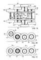
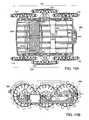
- FIG. 1Ais a plan view of one configuration of wheeled platform in accordance with the invention.
- FIG. 1Bis a side view of the wheeled platform of FIG. 1A, showing a first, “flipper” portion of the platform elevated off the ground plane.
- FIG. 1Cis another side view of the wheeled platform of FIG. 1A, in which the flipper portion has been lowered to make contact with the ground plane.
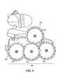
- FIG. 2is a front three-quarter view of a robotic device employing a wheeled platform constructed in accordance with the invention.
- FIG. 3is a three-quarter view of the robotic device of FIG. 2, showing further detail of the wheeled platform constructed in accordance with the invention.
- FIG. 4is a side view of the robotic device of FIG. 2 .
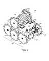
- FIG. 5is an isometric view of the wheeled platform utilized in the robotic device of FIG. 2 .
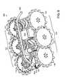
- FIG. 6is a side view of the wheeled platform utilized in the robotic device of FIG. 2 .
- FIG. 7is a plan view of the wheeled platform utilized in the robotic device of FIG. 2 .
- FIG. 8is a perspective view of another embodiment of a wheeled platform according to the invention, with a “tail” element in a retracted position.
- FIG. 9is a perspective view of the wheeled platform of FIG. 8, with the tail element in an extended position.
- FIG. 10Ais a bottom view of the wheeled platform of FIG. 8 .
- FIG. 10Bis a side view of the wheeled platform of FIG. 8, showing detail of the drive elements.
- FIG. 11Ais a top view of the wheeled platform of FIG. 8, showing the tail element in a retracted position.
- FIG. 11Bis another side view of the wheeled platform of FIG. 8 .
- FIG. 11Cis a rear view of the wheeled platform of FIG. 8 .
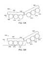
- FIG. 12Ais a side view of another embodiment of a wheeled platform in accordance with the invention.
- FIG. 12Bis a side view of the wheeled platform of FIG. 12A ascending or descending stairs.
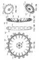
- FIGS. 13A, B, C, D and Eare outside, edge-on and perspective views, respectively, of one embodiment of a wheel element suitable for use in wheeled platforms according to the invention.
- FIG. 14is a schematic diagram of one embodiment of a wheeled platform in accordance with the invention ascending or descending stairs.
- FIGS. 15A, 15 B and 15 Care further schematic diagrams of one embodiment of a wheeled platform in accordance with the invention ascending or descending stairs.
- the present inventionprovides highly agile wheeled platforms that can be used in various transport and robotic applications and operated on rough or steep terrain or surfaces.
- the disclosed platformscan be scaled, by component selection and overall dimension, so as to pass through standard doorways, crawl under standard furniture, and ensure low power consumption.
- the platformscan include motive elements (whether electric, internal combustion or other) so that the platforms can propel themselves on level, uneven, or hilly ground, or over thresholds; maneuver on level terrain or on stairs, turning or changing direction as needed or directed; and spin or turn-in-place, with a turning circle substantially coextensive with the radius of the platform.
- a plurality of wheelsare arrayed on either side (e.g., left/right, port/starboard) of a body or chassis element, and the body or chassis is articulated to permit controlled, relative movement of a first body portion relative to a second body portion about a first axis of rotation.
- the first body portionis referred to as a flipper and the second body portion referred to as a “base”; and the first axis of rotation is substantially perpendicular to a longitudinal (or fore/aft) axis of the platform.
- This substantially perpendicular axis of rotationmay be substantially horizontal, and the rotation or vertical movement of the flipper about that axis can be controlled by a motor or the like, so that the flipper can make selective contact with terrain and/or to control pitch, heave and other motions of the base portion.
- the wheeled platformis equipped with an articulated tail element that can be controlled to make selective contact with terrain.
- the wheel elementscan be disposed about the platform with selected fore-aft overlap between adjacent wheel elements, and such that intermediate wheel elements on each side are displaced outward from a fore/aft axis of the platform, so as to present a wider track at the fore-aft centerline, thus increasing stability while maintaining the ability of the platform to turn-in-place within a small circle.
- wheel diameter, wheel (or axle) spacing and other parameterscan be selected to provide, where desirable, fore/aft overlap of the wheel elements.
- selective rocker of the wheelscan be provided to facilitate turning-in-place and efficient movement over level terrain.
- Independent port and starboard drivescan be provided to enable maneuvers, turns, or turns-in-place; and intermediate wheel elements (in plan view) can be mounted outwardmost, to enable turning-in-place in limited spaces.
- deeply studded or scalloped wheel elementscan be employed at selected wheel locations, to facilitate gripping of stairs.
- the wheels elementsare not overlapping, but wheel diameter and wheel spacing (or axle spacing) are selected to enable the platform to traverse terrain elements, such as stairs and the like, with or without the use of a flipper portion.
- one embodiment of the inventionis a wheeled platform 100 in which first and second sets 102 , 104 of wheel elements are rotatably attached, respectively, to first and second sides 106 , 108 (in this case, left and right, or port and starboard sides) of a body or chassis 110 , wherein a portion of at least one wheel element 112 overlaps a portion of at least one other wheel element 114 in the same set of wheel elements 102 , 104 with the flipper portion 130 in the forward position (see FIG. 1 C).
- wheel element 114overlaps wheel element 112 ; wheel element 116 overlaps wheel element 114 ; and wheel element 116 overlaps wheel element 118 with the flipper portion 130 in the forward position (see FIG. 1 C).
- wheel element 122overlaps wheel element 120 ; wheel element 124 overlaps wheel element 122 ; and wheel element 124 overlaps wheel element 126 (see FIG. 1C; see also FIG. 1 A).
- the platform 100 depicted in FIGS. 1A, 1 B, and 1 Cis advantageously employed in the iRobot commercially available from iRobot Corporation of Somerville, Mass., various aspects of which, including first and second sets of wheel elements 102 , 104 , and wheel elements 112 , 114 , 116 , 118 , 120 , 122 , 124 , and 126 , are depicted in FIGS. 2-7.
- first and second sets of wheel elements 102 , 104 , and wheel elements 112 , 114 , 116 , 118 , 120 , 122 , 124 , and 126are depicted in FIGS. 2-7.
- the structures described hereincan be employed in a wide range of other transport and robotic applications.
- each wheel elementhas a defined radius (which need not be equal for all wheel elements), and a portion of at least one wheel element in a set of wheel elements overlaps another wheel element by a predetermined fraction of the radius of the other wheel element.
- the spacing between at least two wheel element axeswill be less than the sum of the respective radii of the wheel elements.
- the distance between the axes of one wheel element and another wheel element on the same side of the platformwill be less than the diameter of the wheel elements.
- the elements used to rotatably attach the wheel elements to the body portionsmay include axles, pins, bearings, hubs and the like, may be conventional in nature, and the individual selection of particular coupling elements is within the ability of those skilled in the art.
- the wheeled platform 100can have 2, 3, 4, 5 or more “axles”, with 4, 6, 8 or more wheel elements (or even, in some embodiments, an odd number of wheel elements).
- the term “axle”, as used herein,is not limited to a physical axle passing through opposite right and left wheels, but in preferred embodiments can include an axis of rotation of individual wheel elements, which, in some embodiments having port/starboard symmetry, will be common to opposite left and right wheels. It will be understood, however, that the invention can be embodied in nonsymmetrical forms, in which there will not be a common “axle” passing through both left and right wheels.
- the body 110 of the wheeled platform 100includes fore and aft body portions 130 , 132 , and the fore portion is connected to the aft portion via an articulation element 133 .
- This elementcan be a hinge, pivot, or flexible body portion.
- the axis of articulation of the elementcan be substantially perpendicular to a longitudinal axis of the platform, such that the axis of articulation is substantially horizontal.
- Articulationcan also be provided in a transverse direction (i.e., with an axis of rotation about an axis substantially parallel to a longitudinal axis of the platform).
- the articulation elementthus enables the fore portion to act as a “flipper” having selective (and controllable) contact with the terrain, so as to increase the stability of the vehicle when traversing rugged terrain or climbing or descending stairs.
- the illustrated embodimentis an articulated, wheeled platform, in which the articulation can be a substantially horizontal hinge forward of a fore/aft center of the platform.
- a total of eight wheelsare arrayed substantially symmetrically about the plan-view centerline, and the centerline of articulation corresponds substantially to the second axle line, which is defined in this embodiment by the “axle” coupled to wheel elements 114 , 122 .
- wheels 112 and 120are rotatably coupled to the flipper, and the flipper can provide support to the body (or other portion of the body) when traversing difficult or steep terrain or stairs. Examples of the use of the articulating body portions are shown in FIGS. 12 B and 14 - 15 C.
- Conventional angle control or motion control elementssuch as electric motors, can be provided to control the angle of the flipper portion relative to the body as discussed in greater detail below.
- the flipperis designed as to provide for increased stability at various angles of deployment.
- the center of gravity of the entire devicepreferably should be placed as close as possible over the center of wheel elements 116 , 124 .
- the flipper 130should be weighted such that when the flipper 130 is deployed in a forward position (see FIG. 1 C), the center of gravity is moved substantially forward. This allows for greater stability over certain terrain, such as stairs and the like.
- the batteries for the wheeled platformare arranged in the flipper 130 to allow for this movement of the center of gravity.
- the need to control the center of gravitymay or may not be necessary, depending upon the size of the wheels and the expected use of the platform.
- At least one of the intermediate wheel elements on each side of the wheeled structureare displaced outwardly from a longitudinal centerline of the body by an amount greater than that of any end wheel element.
- the centermost wheel or wheels elementshave a wider “track” than the end wheel elements, and the port-side and starboard-side intermediate wheels, in plan view, are displaced outwardly from the body, relative to other wheels in the respective first and second sets of wheel elements.
- intermediate wheel elementis used to denote one, two, three or more wheels per side (port and starboard or left and right) that are longitudinally between “outer” or “comer” wheel elements.
- outboard or comer wheel elementscan number four or more.
- selected wheel elementscan be arbitrarily designated as intermediate wheel elements.
- a selected degree of rockeris provided, such that the point of contact of at least one intermediate wheel element on each side (in FIGS. 1A, 1 B and 1 C, the center wheel in each set of three wheels on the base portion of the platform) can be lower than the respective point of contact of the end wheel elements. This reduces frictional losses when the platform is traversing smooth terrain and surfaces, and facilitates spinning or turning-in-place, thereby increasing agility of the platform.
- drive elementsare provided to drive the wheel elements and to drive the flipper element.
- an independent drive elementis arranged to drive at least one respective wheel element, and control elements are provided for controlling rotation of the respective wheel elements, to enable forward or reverse platform movement, turns or turns-in-place.
- a first set of wheel elementsis coupled to a port side of the body
- a second set of wheel elementsis coupled to a starboard side of the body
- independent port-side and starboard-side drive elementsare provided to enable forward and rearward movement, turns or turns-in-place.
- the wheel elements in selected sets (or subsets) of wheel elementse.g., left or right, port or starboard
- drive module 230is coupled to the first set of wheels 102 ; drive module 231 is coupled to the second set of wheels 104 ; and drive module 134 is coupled to the flipper portion 130 to raise and lower the flipper portion 130 as required.
- Each module 230 , 231 , 134includes a drive motor or element and a corresponding control element.
- the illustrated platformshave three degrees of freedom, including port-side propulsion; starboard-side propulsion; and articulation; and they are conveniently activated by using three independent motors.
- one drive module 230drives all port-side wheels 102 through a reduction gearbox and a spur-gear train; a second drive module 231 drives all starboard-side wheels 104 through a second reduction gearbox and spur-gear train; and a third drive module 134 drives the articulation element 133 through a reduction gearbox and a worm-and-worm wheel train.
- the articulation axisis coincident with a wheel-and-spur gear axis (but this is not necessary to practice the invention), so that the spur gear train can bridge the articulation axis without any complication beyond an inconsequential interaction between actuation of the articulation element 133 and limited rotation of the flipper-mounted wheels 112 , 120 with respect to the base-mounted wheels 114 , 116 , 118 , 122 , 124 , 126 .
- the wheeled platform 800is equipped with an articulated “tail” element 802 , pivotally coupled to a body portion 804 , that can be controlled to make selective contact with terrain.
- the tail element 802can provide support to the body portion 804 when the platform 800 is traversing difficult or steep terrain or stairs.
- FIG. 9depicts the tail element 802 in an extended position to make selective contact with terrain or surfaces.
- platform 800includes first and second sets ( 102 , 104 ) of wheel elements that are rotatably attached, respectively, to port and starboard sides of body portion 804 , such that the corner wheel elements overlap the intermediate wheel element in each set of wheel elements.
- the intermediate wheel element on each sideis displaced outwardly from a centerline of the body portion 804 . In this way, the intermediate wheel elements are wider apart than the comer wheel elements, and thus present a wider track. This aspect is similar to that shown in plan view in FIG. 1 A.
- wheelsmay be spaced apart in a non-overlapping fashion, and that the wheels on each side may be disposed all in a row, rather than offset (i.e., with the intermediate wheels wider apart than the corner wheels).
- the body portion 804can accommodate drive modules 806 , 810 (which may include conventional batteries, electric motors, or the like) and transmission elements 812 (which may include conventional gears, pulleys, belts, chains, or the like).
- the tail element 802can be pivotally coupled to the body portion 804 via a conventional articulation element 814 , which can be a conventional pivot, hinge or the like.
- the angle and position of the tail element 802 relative to the body portion 804can be controlled by a conventional, dedicated motion control or drive element 807 (which can be an electric motor or the like).
- the tail element 802can be driven by a power take-off from a one of the drive modules 806 , 810 used to propel the platform 800 . Power is provided by a battery included in one of the drive modules 806 , 810 .
- the illustrated embodimentreplaces the wheeled flipper of FIGS. 1-7 with an articulated tail in the base's vertical fore-and-aft center plane.
- this configurationhas six (6) wheels arrayed in a formation like that of the base of the first design configuration.
- the curved tail lying in the fore-and-aft vertical center plane of the vehicle, and articulated about a laterally-disposed horizontal axis that is typically at about or just aft the aft-most axle of the vehicle,is long enough to contact a step forward of the first axle of the vehicle, when the tail itself is articulated furthest forward with respect to the base.
- the articulated curved tailcan be under independent control, like the flipper of the first configuration.
- the curved articulated tailmay be swung all the way aft to contact the stairs aft the vehicle, to enhance the vehicle's stability or orientation on the stairs.
- the tail 802 in its fully deployed aft positionshould remain at all times above the plane defined by the wheel elements to avoid interference with stairclimbing. While an articulated tail in the described center plane may be a preferred embodiment, this embodiment of the invention can be configured with the articulated tail in other planes or articulated about even skewed axes.
- FIGS. 12A, 12 BIn alternative embodiments of the invention, fore/aft wheel element overlap is not utilized, but instead, wheel element diameter, wheel spacing, platform-to-wheel spatial displacement, and in one embodiment, flipper dimensions, are selected such that the platform is sufficiently high to avoid contact with obstacles or terrain elements, such as stairs.
- the wheels in this embodimentare disposed sufficiently close together (but without overlap) such that the vehicle can transverse stairs, rocks, thresholds or other obstacles (in some instances, by employing a flipper element), while maintaining the platform at a sufficient ground clearance to avoid ground/obstacle contact.
- FIGS. 12A and 12Bare schematic side views of a wheeled platform 1200 in which the wheel elements are closely spaced, but without overlap.
- the present discussion and FIGS. 12A and 12Brefer focus on one side (for example, the port side) 1201 of platform 1200 .
- the wheel elements and drive mechanisms depicted in FIGS. 12A and 12Bcan be duplicated, identically or non-identically, symmetrically or asymmetrically, on at least one other side (for example, the starboard side) of the wheeled platform 1200 .
- the wheeled platform 1200includes body or chassis portions 1202 , 1204 coupled together by at least one articulation element 1206 , which may be a conventional hinge, pivot, or flexible portion, having an axis of rotation substantially perpendicular to a longitudinal axis of the wheeled platform 1200 .
- wheels 1208 , 1210 , 1212are rotatably coupled to one side 1201 (for example, the port side) of the body portion 1204 by conventional elements (not shown), which may be like those discussed elsewhere in this document with respect to other embodiments of the invention.
- wheels 1214 , 1216 , 1218are rotatably couple to the one side 1201 of the body portion 1202 .
- the axis of rotation of the articulation element 1206is substantially horizontal, so as to permit body portions 1202 , 1204 to move relative to one another in a substantially vertical direction, thus increasing terrain compliance, as shown in FIG. 12 B.
- This articulating ability of the wheeled platform 1200may be advantageously employed in ascending or descending pitches or stairs, as shown in FIG. 12 B.
- motors or other motion-control elementscan be employed to control the angle of body portion 1204 relative to body portion 1202 to facilitate ascending and descending, or reduce frictional losses while moving across relatively smooth surfaces.
- the diameter of the wheel elements, wheel spacing, platform-to-wheel spatial displacement, and body portion dimensionscan be selected such that the platform is sufficiently high to avoid contact with obstacles or terrain elements, such as stairs.
- the wheels in this embodimentare disposed sufficiently close together, and wheel diameter and platform-to-wheel displacement is selected such that the platform can transverse stairs or other obstacles, with the platform having sufficient ground clearance to avoid contact with the nose of each stair.
- articulation elementcan be used, to further segment the body or chassis of the platform 1200 , and that such articulation elements may have an axis of rotation substantially parallel to a longitudinal axis of the platform 1200 .
- right/left or port/starboard articulationmay be provided, in addition to fore/aft articulation.
- more or fewer than 6 wheels on each sidemay be utilized.
- the wheels on each side of the platformmay be disposed all in a row, rather than having the intermediate wheels spaced wider apart (i.e., presenting a wider track) than the comer wheels.
- wheel elements 1300that may be utilized in connection with the invention may include a wheel portion 1302 having a hub 1304 ; and a tire portion 1306 having sidewalls 1308 , 1310 , and a tread portion 1312 that can be either smooth or patterned.
- This patternmay be studded, scalloped or other some similar pattern, whether regular or irregular, symmetrical or asymmetrical.
- FIGS. 13A-13EOne such pattern, shown in FIGS.
- FIGS. 13A-13Econsists of raised, spaced apart blocks 1314 .
- the pattern shown in FIGS. 13A-13Ehas been demonstrated to be advantageous in platforms intended to travel frequently over bullnosed stairs, since the concavity of the scallop portion can effectively engage the rounded (bullnoses) leading edge of each stair-step, increasing traction and reducing slippage.
- a particular practice of the inventionutilizes scalloped wheel elements at the comers of the platform and smooth wheel elements for at least one of intermediate wheel elements on each side.
- the use of smooth wheel elements at the intermediate or center positions on, for example, a 6-wheeled platformfacilitates spins and turn-in-place, while maintaining the terrain-handling advantages (e.g., stair-climbing) afforded by scalloped wheel elements at the 4 comers.
- wheel elementsWhile the use of patterned wheel elements has been shown to be advantageous in certain applications, it will be understood that the invention can be practiced without the use of such wheel elements. Similarly, the invention can be practiced with different forms of wheel/tire elements, and tires (as contrasted with wheel elements) can be omitted.
- FIGS. 14-15Cdepict various platform embodiments in accordance with the invention in stair ascending/descending modes.
- descentsmay be accomplished with the platform arrayed flipper-first (“forward”), or flipper-last (“backward”).
- forwardflipper-first
- flipper-lastbackward
- the flipper anglemay be controlled to prevent the platform from toppling off the landing at the top of a flight of steps; or to smooth out the transition off the stairs onto the bottom landing, although neither operation is necessary for successful descents.
- the platform and its flippercan be operated as depicted in FIGS. 1 B and 15 A- 15 C, with the wheels of the flipper well forward; and with the forward CG, the platform at equilibrium on flat ground rests or operates on the wheels of the other axles.
- the platformcan address stairs in the same configuration, with the flipper raised sufficiently for the wheels of the fore axle to climb over the first step.
- the articulated flippercan be lowered to horizontal, or slightly lower, with respect to the plane of the base, and the platform can proceed up the stairs in this configuration, approximately as shown in FIGS. 15A-15C.
- a more active control of the flipper angle with respect to the basecan be useful for ascents or descents of uneven steps, slippery stairs, or for smoothness of operation, although such active control is not necessary.
- the disclosed inventionthus provides wheeled platforms ideally suited to high-mobility, high-agility applications, including transport, robotic devices and the like, useful on rugged terrain, steep pitches, and stairs, whether indoors or outdoors.
- the structures disclosedare robust, reliable, and conservative of battery or other energy sources, while providing enhanced abilities to traverse challenging terrain and ascend or descend stairs and other obstacles.
- the disclosed platformscan be relatively compact, but scalable by selection of components and overall dimensions to adapt to various expected (and unexpected) terrain requirements.
Landscapes
- Engineering & Computer Science (AREA)
- Chemical & Material Sciences (AREA)
- Combustion & Propulsion (AREA)
- Transportation (AREA)
- Mechanical Engineering (AREA)
- Handcart (AREA)
- Motorcycle And Bicycle Frame (AREA)
Abstract
Description
Claims (16)
Priority Applications (6)
| Application Number | Priority Date | Filing Date | Title |
|---|---|---|---|
| US09/826,209US6662889B2 (en) | 2000-04-04 | 2001-04-04 | Wheeled platforms |
| US10/614,739US7363994B1 (en) | 2000-04-04 | 2003-07-07 | Wheeled platforms |
| US12/023,561US20080143065A1 (en) | 2000-04-04 | 2008-01-31 | Wheeled platforms |
| US12/139,605US8292007B2 (en) | 2000-04-04 | 2008-06-16 | Wheeled platforms |
| US13/657,316US20130214498A1 (en) | 2000-04-04 | 2012-10-22 | Wheeled Platforms |
| US13/893,038US9144361B2 (en) | 2000-04-04 | 2013-05-13 | Debris sensor for cleaning apparatus |
Applications Claiming Priority (2)
| Application Number | Priority Date | Filing Date | Title |
|---|---|---|---|
| US19492200P | 2000-04-04 | 2000-04-04 | |
| US09/826,209US6662889B2 (en) | 2000-04-04 | 2001-04-04 | Wheeled platforms |
Related Child Applications (1)
| Application Number | Title | Priority Date | Filing Date |
|---|---|---|---|
| US10/614,739ContinuationUS7363994B1 (en) | 2000-04-04 | 2003-07-07 | Wheeled platforms |
Publications (2)
| Publication Number | Publication Date |
|---|---|
| US20010047895A1 US20010047895A1 (en) | 2001-12-06 |
| US6662889B2true US6662889B2 (en) | 2003-12-16 |
Family
ID=22719401
Family Applications (5)
| Application Number | Title | Priority Date | Filing Date |
|---|---|---|---|
| US09/826,209Expired - LifetimeUS6662889B2 (en) | 2000-04-04 | 2001-04-04 | Wheeled platforms |
| US10/614,739Expired - Fee RelatedUS7363994B1 (en) | 2000-04-04 | 2003-07-07 | Wheeled platforms |
| US12/023,561AbandonedUS20080143065A1 (en) | 2000-04-04 | 2008-01-31 | Wheeled platforms |
| US12/139,605Expired - Fee RelatedUS8292007B2 (en) | 2000-04-04 | 2008-06-16 | Wheeled platforms |
| US13/657,316AbandonedUS20130214498A1 (en) | 2000-04-04 | 2012-10-22 | Wheeled Platforms |
Family Applications After (4)
| Application Number | Title | Priority Date | Filing Date |
|---|---|---|---|
| US10/614,739Expired - Fee RelatedUS7363994B1 (en) | 2000-04-04 | 2003-07-07 | Wheeled platforms |
| US12/023,561AbandonedUS20080143065A1 (en) | 2000-04-04 | 2008-01-31 | Wheeled platforms |
| US12/139,605Expired - Fee RelatedUS8292007B2 (en) | 2000-04-04 | 2008-06-16 | Wheeled platforms |
| US13/657,316AbandonedUS20130214498A1 (en) | 2000-04-04 | 2012-10-22 | Wheeled Platforms |
Country Status (3)
| Country | Link |
|---|---|
| US (5) | US6662889B2 (en) |
| AU (1) | AU2001253151A1 (en) |
| WO (1) | WO2001074652A2 (en) |
Cited By (83)
| Publication number | Priority date | Publication date | Assignee | Title |
|---|---|---|---|---|
| US20040216931A1 (en)* | 1998-03-27 | 2004-11-04 | Chikyung Won | Robotic platform |
| US20050161237A1 (en)* | 2002-04-04 | 2005-07-28 | Gedalyahu Manor | Method of cleaning hole diggers and spot cultivators and hole digger cleaning device |
| US7011171B1 (en)* | 2002-10-08 | 2006-03-14 | Poulter Andrew R | Rugged terrain robot |
| US20060095169A1 (en)* | 2004-04-15 | 2006-05-04 | Minor Mark A | System and method for controlling modular robots |
| US7155308B2 (en) | 2000-01-24 | 2006-12-26 | Irobot Corporation | Robot obstacle detection system |
| US20070251735A1 (en)* | 2005-04-14 | 2007-11-01 | Sony Corporation | Coaxial two-wheel vehicle |
| US7332890B2 (en) | 2004-01-21 | 2008-02-19 | Irobot Corporation | Autonomous robot auto-docking and energy management systems and methods |
| US7348747B1 (en) | 2006-03-30 | 2008-03-25 | Vecna | Mobile robot platform |
| US20080105481A1 (en)* | 2006-11-02 | 2008-05-08 | Hutcheson Timothy L | Reconfigurable balancing robot and method for dynamically transitioning between statically stable mode and dynamically balanced mode |
| USD569923S1 (en) | 2006-05-04 | 2008-05-27 | Mattel, Inc. | Snake toy vehicle |
| US7389156B2 (en) | 2005-02-18 | 2008-06-17 | Irobot Corporation | Autonomous surface cleaning robot for wet and dry cleaning |
| US20080209665A1 (en)* | 2005-07-20 | 2008-09-04 | Mangiardi John R | Robotic Floor Cleaning with Sterile, Disposable Cartridges Cross-Reference to Related Applications |
| US20080308326A1 (en)* | 2007-06-14 | 2008-12-18 | Alstom Technology Ltd | Automotive inspection device |
| US7475745B1 (en) | 2006-05-11 | 2009-01-13 | Deroos Bradley G | High mobility vehicle |
| US20090137186A1 (en)* | 2006-05-04 | 2009-05-28 | Mattel, Inc. | Motorized toy creature |
| US7620476B2 (en) | 2005-02-18 | 2009-11-17 | Irobot Corporation | Autonomous surface cleaning robot for dry cleaning |
| US20090314554A1 (en)* | 2006-10-06 | 2009-12-24 | Irobot Corporation | Robotic vehicle |
| US20100037418A1 (en)* | 2005-12-02 | 2010-02-18 | Irobot Corporation | Autonomous Coverage Robots |
| US7706917B1 (en) | 2004-07-07 | 2010-04-27 | Irobot Corporation | Celestial navigation system for an autonomous robot |
| US20100116566A1 (en)* | 2006-10-06 | 2010-05-13 | Irobot Corporation | Maneuvering Robotic Vehicles Having A Positionable Sensor Head |
| US7761954B2 (en) | 2005-02-18 | 2010-07-27 | Irobot Corporation | Autonomous surface cleaning robot for wet and dry cleaning |
| US20110144805A1 (en)* | 2002-09-13 | 2011-06-16 | Chiappetta Mark J | Navigational control system for a robotic device |
| US20110233991A1 (en)* | 2010-03-29 | 2011-09-29 | Robosynthesis Limited | Wheel and Wheel Assembly |
| US8239992B2 (en) | 2007-05-09 | 2012-08-14 | Irobot Corporation | Compact autonomous coverage robot |
| US8253368B2 (en) | 2004-01-28 | 2012-08-28 | Irobot Corporation | Debris sensor for cleaning apparatus |
| US8368339B2 (en) | 2001-01-24 | 2013-02-05 | Irobot Corporation | Robot confinement |
| US8374721B2 (en) | 2005-12-02 | 2013-02-12 | Irobot Corporation | Robot system |
| US8380350B2 (en) | 2005-12-02 | 2013-02-19 | Irobot Corporation | Autonomous coverage robot navigation system |
| US8382906B2 (en) | 2005-02-18 | 2013-02-26 | Irobot Corporation | Autonomous surface cleaning robot for wet cleaning |
| US8386081B2 (en) | 2002-09-13 | 2013-02-26 | Irobot Corporation | Navigational control system for a robotic device |
| US8396592B2 (en) | 2001-06-12 | 2013-03-12 | Irobot Corporation | Method and system for multi-mode coverage for an autonomous robot |
| US8412377B2 (en) | 2000-01-24 | 2013-04-02 | Irobot Corporation | Obstacle following sensor scheme for a mobile robot |
| US8417383B2 (en) | 2006-05-31 | 2013-04-09 | Irobot Corporation | Detecting robot stasis |
| US8418303B2 (en) | 2006-05-19 | 2013-04-16 | Irobot Corporation | Cleaning robot roller processing |
| US8428778B2 (en) | 2002-09-13 | 2013-04-23 | Irobot Corporation | Navigational control system for a robotic device |
| US8463438B2 (en) | 2001-06-12 | 2013-06-11 | Irobot Corporation | Method and system for multi-mode coverage for an autonomous robot |
| US8474090B2 (en) | 2002-01-03 | 2013-07-02 | Irobot Corporation | Autonomous floor-cleaning robot |
| US20130178981A1 (en)* | 2012-01-06 | 2013-07-11 | Tit Shing Wong | Interactive apparatus |
| US8584305B2 (en) | 2005-12-02 | 2013-11-19 | Irobot Corporation | Modular robot |
| US8600553B2 (en) | 2005-12-02 | 2013-12-03 | Irobot Corporation | Coverage robot mobility |
| US20130328290A1 (en)* | 2011-02-11 | 2013-12-12 | Mehran Mehrandezh | Adaptable vehicle |
| US20140166377A1 (en)* | 2011-06-29 | 2014-06-19 | Bluebotics Sa | Mobile Robot |
| US8780342B2 (en) | 2004-03-29 | 2014-07-15 | Irobot Corporation | Methods and apparatus for position estimation using reflected light sources |
| US8788092B2 (en) | 2000-01-24 | 2014-07-22 | Irobot Corporation | Obstacle following sensor scheme for a mobile robot |
| US8800107B2 (en) | 2010-02-16 | 2014-08-12 | Irobot Corporation | Vacuum brush |
| US8800695B2 (en) | 2006-10-06 | 2014-08-12 | Irobot Corporation | Robotic vehicle |
| US20140300211A1 (en)* | 2013-03-06 | 2014-10-09 | Massachusetts Institute Of Technology | Discrete Motion System |
| US8930023B2 (en) | 2009-11-06 | 2015-01-06 | Irobot Corporation | Localization by learning of wave-signal distributions |
| US8972052B2 (en) | 2004-07-07 | 2015-03-03 | Irobot Corporation | Celestial navigation system for an autonomous vehicle |
| US9008835B2 (en) | 2004-06-24 | 2015-04-14 | Irobot Corporation | Remote control scheduler and method for autonomous robotic device |
| US9452097B2 (en) | 2014-03-31 | 2016-09-27 | Clive Lu | Electric mobility vehicle |
| US9811089B2 (en) | 2013-12-19 | 2017-11-07 | Aktiebolaget Electrolux | Robotic cleaning device with perimeter recording function |
| US9939529B2 (en) | 2012-08-27 | 2018-04-10 | Aktiebolaget Electrolux | Robot positioning system |
| US9946263B2 (en) | 2013-12-19 | 2018-04-17 | Aktiebolaget Electrolux | Prioritizing cleaning areas |
| US10045675B2 (en) | 2013-12-19 | 2018-08-14 | Aktiebolaget Electrolux | Robotic vacuum cleaner with side brush moving in spiral pattern |
| US20180229572A1 (en)* | 2015-11-02 | 2018-08-16 | Starship Technologies Oü | System and method for traversing vertical obstacles |
| US10149589B2 (en) | 2013-12-19 | 2018-12-11 | Aktiebolaget Electrolux | Sensing climb of obstacle of a robotic cleaning device |
| US10209080B2 (en) | 2013-12-19 | 2019-02-19 | Aktiebolaget Electrolux | Robotic cleaning device |
| US10219665B2 (en) | 2013-04-15 | 2019-03-05 | Aktiebolaget Electrolux | Robotic vacuum cleaner with protruding sidebrush |
| US10231591B2 (en) | 2013-12-20 | 2019-03-19 | Aktiebolaget Electrolux | Dust container |
| US10433697B2 (en) | 2013-12-19 | 2019-10-08 | Aktiebolaget Electrolux | Adaptive speed control of rotating side brush |
| US10448794B2 (en) | 2013-04-15 | 2019-10-22 | Aktiebolaget Electrolux | Robotic vacuum cleaner |
| US10499778B2 (en) | 2014-09-08 | 2019-12-10 | Aktiebolaget Electrolux | Robotic vacuum cleaner |
| US10518416B2 (en) | 2014-07-10 | 2019-12-31 | Aktiebolaget Electrolux | Method for detecting a measurement error in a robotic cleaning device |
| US10534367B2 (en) | 2014-12-16 | 2020-01-14 | Aktiebolaget Electrolux | Experience-based roadmap for a robotic cleaning device |
| US10617271B2 (en) | 2013-12-19 | 2020-04-14 | Aktiebolaget Electrolux | Robotic cleaning device and method for landmark recognition |
| US10678251B2 (en) | 2014-12-16 | 2020-06-09 | Aktiebolaget Electrolux | Cleaning method for a robotic cleaning device |
| US10729297B2 (en) | 2014-09-08 | 2020-08-04 | Aktiebolaget Electrolux | Robotic vacuum cleaner |
| US10877484B2 (en) | 2014-12-10 | 2020-12-29 | Aktiebolaget Electrolux | Using laser sensor for floor type detection |
| US10874274B2 (en) | 2015-09-03 | 2020-12-29 | Aktiebolaget Electrolux | System of robotic cleaning devices |
| US10874271B2 (en) | 2014-12-12 | 2020-12-29 | Aktiebolaget Electrolux | Side brush and robotic cleaner |
| US11099554B2 (en) | 2015-04-17 | 2021-08-24 | Aktiebolaget Electrolux | Robotic cleaning device and a method of controlling the robotic cleaning device |
| US11122953B2 (en) | 2016-05-11 | 2021-09-21 | Aktiebolaget Electrolux | Robotic cleaning device |
| US11169533B2 (en) | 2016-03-15 | 2021-11-09 | Aktiebolaget Electrolux | Robotic cleaning device and a method at the robotic cleaning device of performing cliff detection |
| US20220153365A1 (en)* | 2020-11-16 | 2022-05-19 | Toyota Jidosha Kabushiki Kaisha | Motor-driven vehicle |
| US11474533B2 (en) | 2017-06-02 | 2022-10-18 | Aktiebolaget Electrolux | Method of detecting a difference in level of a surface in front of a robotic cleaning device |
| US11572117B2 (en)* | 2015-11-02 | 2023-02-07 | Starship Technologies Oü | Obstacle traversing mobile robot |
| USD1006898S1 (en)* | 2020-09-10 | 2023-12-05 | MerchSource, LLC | Toy car |
| US11921517B2 (en) | 2017-09-26 | 2024-03-05 | Aktiebolaget Electrolux | Controlling movement of a robotic cleaning device |
| RU2839732C1 (en)* | 2024-11-07 | 2025-05-12 | Федеральное государственное бюджетное образовательное учреждение высшего образования "Воронежский государственный технический университет" (ВГТУ) | Information mobile robot |
| US12296694B2 (en) | 2021-03-10 | 2025-05-13 | Techtronic Cordless Gp | Lawnmowers |
| US12369509B2 (en) | 2022-07-19 | 2025-07-29 | Techtronic Cordless Gp | Display for controlling robotic tool |
| US12425197B2 (en) | 2022-07-29 | 2025-09-23 | Techtronic Cordless Gp | Generation of a cryptography key for a robotic garden tool |
Families Citing this family (61)
| Publication number | Priority date | Publication date | Assignee | Title |
|---|---|---|---|---|
| CA2412815A1 (en)* | 2002-11-27 | 2004-05-27 | Martin Deschambault | Mobile and modular robot platform with several means of locomotion for making advanced movements in three dimensions |
| US7805220B2 (en) | 2003-03-14 | 2010-09-28 | Sharper Image Acquisition Llc | Robot vacuum with internal mapping system |
| US20040200505A1 (en)* | 2003-03-14 | 2004-10-14 | Taylor Charles E. | Robot vac with retractable power cord |
| US7801645B2 (en) | 2003-03-14 | 2010-09-21 | Sharper Image Acquisition Llc | Robotic vacuum cleaner with edge and object detection system |
| US20040244138A1 (en)* | 2003-03-14 | 2004-12-09 | Taylor Charles E. | Robot vacuum |
| US7456596B2 (en)* | 2005-08-19 | 2008-11-25 | Cisco Technology, Inc. | Automatic radio site survey using a robot |
| US8644991B2 (en)* | 2006-10-06 | 2014-02-04 | Irobot Corporation | Maneuvering robotic vehicles |
| US7562728B1 (en)* | 2006-10-12 | 2009-07-21 | Allan Alfred Voigt | Powered wheelchair |
| IL181208A (en)* | 2007-02-07 | 2011-02-28 | Elbit Systems Ltd | Unmanned robot vehicle with mobility enhancing arm |
| US8260459B2 (en)* | 2008-05-08 | 2012-09-04 | Regents Of The University Of Minnesota | Robotic vehicle system |
| US8442661B1 (en) | 2008-11-25 | 2013-05-14 | Anybots 2.0, Inc. | Remotely controlled self-balancing robot including a stabilized laser pointer |
| KR20110120867A (en) | 2008-12-09 | 2011-11-04 | 레콘로보틱스, 아이엔씨 | Two-wheeled robot with improved climbing characteristics |
| US20110031044A1 (en)* | 2009-08-04 | 2011-02-10 | Ehud Gal | Robotic platform & methods for overcoming obstacles |
| US8527113B2 (en)* | 2009-08-07 | 2013-09-03 | Irobot Corporation | Remote vehicle |
| US20110054690A1 (en)* | 2009-08-25 | 2011-03-03 | Ehud Gal | Electro-mechanism for extending the capabilities of bilateral robotic platforms and a method for performing the same |
| US20110061951A1 (en)* | 2009-09-14 | 2011-03-17 | Ehud Gal | Transformable Robotic Platform and Methods for Overcoming Obstacles |
| USD626577S1 (en)* | 2009-12-09 | 2010-11-02 | ReconRobotics Inc. | Two wheeled robot with enhanced climbing features |
| FR2956087B1 (en)* | 2010-02-05 | 2012-12-28 | New Live | OBSTACLE CROSSING DEVICE FOR ELECTRICAL WHEELCHAIR. |
| US8594844B1 (en) | 2010-02-09 | 2013-11-26 | Defense Vision Ltd | Single operator multitask robotic platform |
| US8788096B1 (en) | 2010-05-17 | 2014-07-22 | Anybots 2.0, Inc. | Self-balancing robot having a shaft-mounted head |
| WO2012044663A1 (en) | 2010-09-30 | 2012-04-05 | Schlee Keith L | Multi-unit mobile robot |
| US9522595B2 (en) | 2011-01-27 | 2016-12-20 | Irobot Defense Holdings, Inc. | Small unmanned ground vehicle |
| US9346499B2 (en) | 2011-01-27 | 2016-05-24 | Irobot Corporation | Resilient wheel assemblies |
| PL2530311T3 (en)* | 2011-06-01 | 2015-03-31 | Gamesa Innovation & Tech Sl | Inspection trolley |
| KR20130049029A (en)* | 2011-11-03 | 2013-05-13 | 삼성전자주식회사 | Walking robot and control method for thereof |
| US9168786B2 (en) | 2011-12-02 | 2015-10-27 | Helical Robotics, Llc | Mobile robot |
| RU2486094C1 (en)* | 2012-04-05 | 2013-06-27 | Николай Петрович Дядченко | Chassis |
| RU2495655C1 (en)* | 2012-05-29 | 2013-10-20 | Дядченко Н.П. | Self-positioned dual wheel gear |
| FR2991654A1 (en)* | 2012-06-08 | 2013-12-13 | Pierre Yves Duchesne | MOTORIZED ALL-TERRAIN ROBOT HAS AT LEAST FOUR WHEELS |
| US10136954B2 (en)* | 2012-06-21 | 2018-11-27 | Globus Medical, Inc. | Surgical tool systems and method |
| US8434576B1 (en) | 2012-08-21 | 2013-05-07 | Andrew Ferguson | Mobile reconnaissance apparatus with articulating traction control |
| CA2787075C (en) | 2012-08-22 | 2013-10-29 | Draganfly Holdings Inc. | Wheel with folding segments |
| US10287063B2 (en)* | 2012-10-24 | 2019-05-14 | Illinois Tool Works Inc. | Child-resistant reclosable bags |
| CN102897240A (en)* | 2012-11-09 | 2013-01-30 | 西南大学 | Driving wheel combined mechanism |
| US10106215B2 (en)* | 2014-05-24 | 2018-10-23 | James Walter Beard, III | One-dimensional climbing vehicle with resilient guide mechanism |
| RU2547967C1 (en)* | 2014-06-09 | 2015-04-10 | Николай Петрович Дядченко | Wheel-caterpillar mover |
| US10046819B1 (en) | 2014-06-23 | 2018-08-14 | Reconrobotics, Inc. | Throwable robot with clamshell body |
| JP6027064B2 (en)* | 2014-08-20 | 2016-11-16 | 阪神高速技術株式会社 | Inspection robot |
| CN104760629A (en)* | 2015-03-25 | 2015-07-08 | 南宁市第一中学 | Ladder climbing mechanism |
| KR102412122B1 (en)* | 2015-05-27 | 2022-06-23 | 삼성전자주식회사 | Method and apparatus for displaying medical image |
| CA174441S (en) | 2015-10-07 | 2018-01-02 | Starship Tech Oü | Delivery robot |
| JP1578668S (en)* | 2016-08-29 | 2017-06-12 | ||
| USD821265S1 (en) | 2017-03-23 | 2018-06-26 | Starship Technologies Oü | Vehicle |
| US20220413493A1 (en)* | 2017-05-12 | 2022-12-29 | Gary Graf | Obstacle climbing surveillance robot and energy-absorbing frame therefor |
| WO2018208636A1 (en)* | 2017-05-12 | 2018-11-15 | Graf Gary | Obstacle climbing surveillance robot and energy-absorbing frame therefor |
| WO2018215581A1 (en) | 2017-05-26 | 2018-11-29 | Starship Technologies Oü | A battery and a system for swapping and/or charging a battery of a mobile robot |
| CN107352205B (en)* | 2017-07-18 | 2023-09-08 | 北京极智嘉科技股份有限公司 | Transfer robot |
| EP3659104B1 (en) | 2017-07-28 | 2024-01-17 | Starship Technologies OÜ | Device and system for secure package delivery by a mobile robot |
| US12194824B2 (en) | 2017-08-15 | 2025-01-14 | Reconrobotics, Inc. | Two wheel robot with convertibility and accessories |
| US10589430B2 (en) | 2017-08-15 | 2020-03-17 | Reconrobotics, Inc. | Throwable robot with improved drive system |
| US10987818B2 (en) | 2017-08-15 | 2021-04-27 | Reconrobotics, Inc. | Magnetic lock for throwable robot |
| EP3668687B1 (en) | 2017-08-15 | 2022-11-09 | Reconrobotics, Inc. | Two wheeled robot with convertibility and accessories |
| US10828973B2 (en) | 2017-08-15 | 2020-11-10 | Reconrobtics, Inc. | Two wheel robot with convertibility and accessories |
| TWD189310S (en)* | 2017-09-08 | 2018-03-21 | 趙嘉浩 | Robot body structure |
| TWD189311S (en)* | 2017-09-08 | 2018-03-21 | 趙嘉浩 | Robot's eyelid structure |
| US10807246B2 (en)* | 2018-01-08 | 2020-10-20 | Beijing Jingdong Shangke Information Technology Co., Ltd. | Mobile robotic device and method of controlling the same manipulator for locomotion and manipulation |
| KR102046617B1 (en)* | 2019-03-29 | 2019-11-19 | 주식회사 가나오엠 | Anti-slip wheel and imaging device therewith for under ground structure |
| RU196942U1 (en)* | 2019-09-17 | 2020-03-23 | Федеральное государственное казенное военное образовательное учреждение высшего образования "Военная академия материально-технического обеспечения имени генерала армии А.В. Хрулёва" | Robotic transport platform |
| FR3103128B1 (en)* | 2019-11-19 | 2022-07-29 | Meropy | Autonomous robot |
| CN114714323B (en)* | 2022-04-18 | 2024-02-06 | 中国矿业大学 | A wheeled module assembly suitable for reconstructing modular robots |
| CN117248733B (en)* | 2023-06-08 | 2025-02-18 | 浙江孚帝克科技有限公司 | An intelligent vibrating robot |
Citations (28)
| Publication number | Priority date | Publication date | Assignee | Title |
|---|---|---|---|---|
| GB875691A (en) | 1957-07-16 | 1961-08-23 | Ernst Meili | Improvements in or relating to motor-driven vehicles |
| US3235020A (en) | 1962-09-19 | 1966-02-15 | Gen Motors Corp | Vehicle with flexible frame |
| US3540151A (en)* | 1968-12-04 | 1970-11-17 | Eldon Ind Inc | Moving vehicle type toy |
| DE1630748A1 (en) | 1964-04-01 | 1971-01-21 | Lifferth Internat Corp Fa | Vehicle for road and off-road driving |
| US3799362A (en)* | 1973-01-22 | 1974-03-26 | Standard Mfg Co | Six wheel material handling vehicle |
| US3809004A (en)* | 1972-09-18 | 1974-05-07 | W Leonheart | All terrain vehicle |
| US4009761A (en) | 1975-05-02 | 1977-03-01 | Irvin L. Stumpf | Skid steer vehicle |
| US4247125A (en)* | 1978-05-08 | 1981-01-27 | Rayment Ena M | Wheelchair |
| EP0206930A1 (en) | 1985-06-21 | 1986-12-30 | Commissariat A L'energie Atomique | Variable geometry tracked vehicle |
| US4674585A (en)* | 1985-12-27 | 1987-06-23 | Gordon Barlow Design | Articulated unit vehicle |
| US4730684A (en) | 1986-07-22 | 1988-03-15 | Borge Pedersen | Vehicle |
| WO1989000928A1 (en) | 1987-07-24 | 1989-02-09 | Karlin, Gunvor (Legal Representative For The Estat | Cross-country vehicle |
| US4813906A (en)* | 1985-10-19 | 1989-03-21 | Tomy Kogyo Co., Inc. | Pivotable running toy |
| US4919489A (en)* | 1988-04-20 | 1990-04-24 | Grumman Aerospace Corporation | Cog-augmented wheel for obstacle negotiation |
| US4932491A (en) | 1989-03-21 | 1990-06-12 | The United States Of America As Represented By The Administrator Of The National Aeronautics And Space Administration | Body steered rover |
| US4993912A (en) | 1989-12-22 | 1991-02-19 | Chamberlain Mrc, Division Of Duchossois Industries, Inc. | Stair climbing robot |
| JPH0632263A (en)* | 1992-07-15 | 1994-02-08 | Tomita Denki Seisakusho:Kk | Legged moving vehicle |
| US5323867A (en)* | 1992-03-06 | 1994-06-28 | Eric J. Allard | Robot transport platform with multi-directional wheels |
| GB2280650A (en) | 1993-08-06 | 1995-02-08 | Gordon George Coleman | Metal spiked golf trolley wheels |
| US5429543A (en)* | 1992-07-31 | 1995-07-04 | Tyco Investment Corp. | Vehicle toy |
| US5507358A (en) | 1993-06-04 | 1996-04-16 | Kabushiki Kaisha Daikin Seisakusho | Stair climbing vehicle |
| US5515934A (en) | 1994-10-17 | 1996-05-14 | Davis; Stuart D. | Agile versatile mobile robot body |
| NL1002503A1 (en) | 1995-03-02 | 1996-09-11 | Kurstjens Terra Gator B V | Vehicle. |
| US5742975A (en) | 1996-05-06 | 1998-04-28 | Windsor Industries, Inc. | Articulated floor scrubber |
| US5752871A (en)* | 1995-11-30 | 1998-05-19 | Tomy Co., Ltd. | Running body |
| US5833248A (en) | 1996-05-23 | 1998-11-10 | Exedy Corporation | Stairway ascending/descending vehicle having an arm member with a torque transmitting configuration |
| US6046565A (en)* | 1998-06-19 | 2000-04-04 | Thorne; Henry F. | Robotic vehicle with deduced reckoning positioning system |
| US6144180A (en) | 1999-07-09 | 2000-11-07 | Chen; Chun-Ta | Mobile robot |
Family Cites Families (67)
| Publication number | Priority date | Publication date | Assignee | Title |
|---|---|---|---|---|
| US1069761A (en)* | 1911-07-21 | 1913-08-12 | Andrew A Johnson | Sled. |
| US2917120A (en)* | 1954-12-17 | 1959-12-15 | Gates Joseph Harold | Combination wheeled and crawler type support for vehicles |
| US3068950A (en)* | 1961-10-10 | 1962-12-18 | Isaac F Davidson | Adjustable motor-driven invalid chair with endless tracks |
| US3166138A (en)* | 1961-10-26 | 1965-01-19 | Jr Edward D Dunn | Stair climbing conveyance |
| US3283839A (en)* | 1965-03-02 | 1966-11-08 | Ronald K Brown | Stair-climbing wheel chair |
| US3311424A (en)* | 1965-06-03 | 1967-03-28 | Marval & O Farrell | Tractive device comprising a belt driven soft roller |
| US3295858A (en)* | 1965-10-20 | 1967-01-03 | Jr Harry W Addison | Stair traversing wheel chair mechanism |
| GB1121262A (en)* | 1966-07-04 | 1968-07-24 | Atlas Copco Ab | Improvements in shovel loaders |
| US3417832A (en)* | 1966-10-24 | 1968-12-24 | William B Jaspert | Wheeled vehicle selectively convertible to endless track vehicle |
| GB1218741A (en)* | 1967-02-10 | 1971-01-13 | Atomic Energy Authority Uk | Improvements in or relating to vehicles |
| US3444583A (en)* | 1967-04-20 | 1969-05-20 | Melroe Mfg Co | Vehicle with lift-off means for ease of steering |
| US3489236A (en)* | 1968-08-01 | 1970-01-13 | Us Army | Egressing device for military vehicles |
| US3649981A (en)* | 1970-02-25 | 1972-03-21 | Wayne Manufacturing Co | Curb travelling sweeper vehicle |
| US3891234A (en)* | 1972-03-13 | 1975-06-24 | Marx Toys Division Of The Quak | Toy vehicle for transporting at least the vehicle operator |
| NL7408500A (en)* | 1974-06-25 | 1975-12-30 | Lely Nv C Van Der | TRACTOR. |
| US4027889A (en)* | 1975-11-10 | 1977-06-07 | Kando Incorporated | Stair-climbing carrier |
| US4492058A (en)* | 1980-02-14 | 1985-01-08 | Adolph E. Goldfarb | Ultracompact miniature toy vehicle with four-wheel drive and unusual climbing capability |
| US4280544A (en)* | 1980-03-14 | 1981-07-28 | B R International | Tire traction device |
| US4369989A (en)* | 1980-08-01 | 1983-01-25 | Standard Manufacturing Company, Incorporated | Stabilizing jack for skid steer vehicle |
| US4483407A (en)* | 1982-03-26 | 1984-11-20 | Hitachi, Ltd. | Variable configuration track laying vehicle |
| GB2126540B (en)* | 1982-09-10 | 1986-07-16 | Robert Hester | Stairclimbing vehicles |
| US4688813A (en)* | 1982-12-28 | 1987-08-25 | Sunwa Sharyo Manufacturing Co., Ltd. | Carrier for rescuing patients |
| EP0114628B1 (en)* | 1983-01-21 | 1987-07-15 | Ruedi Bieli-Möschlin | Repair device for straightening steel containers |
| US4687068A (en)* | 1983-01-25 | 1987-08-18 | Australian Transcenders International Pty. Ltd. | Invalid's wheelchair and like conveyances |
| US4477998A (en)* | 1983-05-31 | 1984-10-23 | You Yun Long | Fantastic wall-climbing toy |
| US4566551A (en)* | 1983-08-30 | 1986-01-28 | Feliz Jack M | Stair-climbing conveyance |
| JPS6078864A (en)* | 1983-10-07 | 1985-05-04 | サンワ車輌株式会社 | Stair lifting gear for wheelchair |
| JPS60176871A (en) | 1984-02-24 | 1985-09-10 | Toshiba Corp | robot traveling device |
| US4823900A (en)* | 1984-05-01 | 1989-04-25 | Jeffrey Farnam | Four-wheel drive wheel-chair with compound wheels |
| FR2574740B1 (en)* | 1984-12-18 | 1987-10-23 | 3 14 Applic Multiples | EQUIPMENT FOR CROSSING OBSTACLES, FOR A WHEELCHAIR FOR A DISABLED PERSON |
| JPS61271176A (en)* | 1985-05-28 | 1986-12-01 | Mitsubishi Electric Corp | Mobile machine |
| US4671369A (en)* | 1985-10-01 | 1987-06-09 | Gordon W. Rosenberg | Stair-climbing wheelchair with means for cushioning vertical movements thereof |
| DE3622076A1 (en)* | 1986-07-01 | 1988-01-21 | Ralf Bohle & Co Gmbh | Tyre for a wheelchair |
| DE3781994T2 (en)* | 1986-10-20 | 1993-02-18 | Hoky Kk | FLOOR CLEANER. |
| AT393251B (en)* | 1987-10-20 | 1991-09-25 | Lehner Max | WITH A WHEELCHAIR COUPLING TRACK TRANSPORT DEVICE, ESPECIALLY FOR DRIVING STAIRS |
| US4915184A (en)* | 1988-06-10 | 1990-04-10 | Quest Technologies Corp. | Cushioning mechanism for stair-climbing wheelchair |
| US4932831A (en)* | 1988-09-26 | 1990-06-12 | Remotec, Inc. | All terrain mobile robot |
| DE3900889A1 (en)* | 1989-01-13 | 1990-07-19 | Arnolf Schulte | LOCKABLE STEERING WHEEL |
| US4962941A (en)* | 1989-03-22 | 1990-10-16 | Rembos Steven N | Wheelchair apparatus |
| US4977971A (en)* | 1989-05-17 | 1990-12-18 | University Of Florida | Hybrid robotic vehicle |
| FR2651201B1 (en)* | 1989-08-31 | 1991-10-25 | Framatome Sa | VEHICLE WITH INCLINABLE TRACKS. |
| US5248008A (en)* | 1989-08-31 | 1993-09-28 | Framatome | Self-traveling robotic vehicle with inclinable propulsion units |
| DE4028773C2 (en)* | 1989-09-28 | 1994-11-10 | Schaeff Karl Gmbh & Co | Walking vehicle |
| EP0541810B1 (en)* | 1990-08-08 | 1996-10-23 | Kabushiki Kaisha Komatsu Seisakusho | Disaster relief robot and its operation controller |
| JP2551862B2 (en)* | 1990-10-18 | 1996-11-06 | 株式会社サンワ | Wheelchair stair lift |
| US5158309A (en)* | 1990-12-06 | 1992-10-27 | Quigg Robert T | Stair climbing apparatus for collapsible wheelchair |
| US5884718A (en)* | 1993-08-11 | 1999-03-23 | Nikon Corporation | Traveling apparatus, and control method and rotational-angle detector applied thereto |
| IT1273260B (en)* | 1994-03-21 | 1997-07-07 | Tgr Srl | TRACKED VEHICLE, SUITABLE FOR ADDRESSING ANY TYPE OF ROUTE, INCLUDING THE ASCENT AND DESCENT OF STAIRS AND PARTICULARLY SUITABLE FOR THE CONSTRUCTION OF WHEELCHAIRS FOR INVALID |
| US5513716A (en)* | 1994-05-09 | 1996-05-07 | Trustees Of The University Of Pennsylvania | Adaptive mobility system |
| JP3396977B2 (en) | 1994-11-30 | 2003-04-14 | 松下電器産業株式会社 | Mobile work robot |
| US5944131A (en)* | 1996-07-03 | 1999-08-31 | Pride Health Care, Inc. | Mid-wheel drive power wheelchair |
| JP3860266B2 (en)* | 1996-10-29 | 2006-12-20 | 株式会社サンワ | Stair lift truck for wheelchair |
| US6112843A (en)* | 1996-11-07 | 2000-09-05 | California Institute Of Technology | High mobility vehicle |
| US5868403A (en)* | 1996-12-20 | 1999-02-09 | Culp; John A. | Medical transport device |
| JPH10250645A (en)* | 1997-03-17 | 1998-09-22 | Nikon Corp | Traveling device that can move up and down stairs |
| DE29720939U1 (en)* | 1997-11-26 | 1999-04-01 | Otto Bock Orthopädische Industrie Besitz- und Verwaltungs-Kommanditgesellschaft, 37115 Duderstadt | Safety device for stair climbing devices |
| US6099091A (en)* | 1998-01-20 | 2000-08-08 | Letro Products, Inc. | Traction enhanced wheel apparatus |
| EP0945337A1 (en)* | 1998-03-27 | 1999-09-29 | Single Buoy Moorings Inc. | Mooring construction |
| US6263989B1 (en)* | 1998-03-27 | 2001-07-24 | Irobot Corporation | Robotic platform |
| AUPP670498A0 (en)* | 1998-10-23 | 1998-11-19 | Roller Chair Pty Ltd | Improved mid-wheel drive wheelchair |
| US6250409B1 (en)* | 1999-09-01 | 2001-06-26 | Glenn D. Wells | Multi-point mobility device |
| US7011171B1 (en)* | 2002-10-08 | 2006-03-14 | Poulter Andrew R | Rugged terrain robot |
| US7172488B2 (en)* | 2003-11-12 | 2007-02-06 | Mattel, Inc. | Toy vehicle |
| US7581605B2 (en)* | 2006-02-22 | 2009-09-01 | Mga Entertainment, Inc. | Quad tracked vehicle |
| US7874386B2 (en)* | 2007-05-11 | 2011-01-25 | Pinhas Ben-Tzvi | Hybrid mobile robot |
| US20080296853A1 (en)* | 2007-06-01 | 2008-12-04 | Langford Christopher J | Stair assist robot mechanism and method |
| US7926598B2 (en)* | 2008-12-09 | 2011-04-19 | Irobot Corporation | Mobile robotic vehicle |
- 2001
- 2001-04-04AUAU2001253151Apatent/AU2001253151A1/ennot_activeAbandoned
- 2001-04-04USUS09/826,209patent/US6662889B2/ennot_activeExpired - Lifetime
- 2001-04-04WOPCT/US2001/011017patent/WO2001074652A2/enactiveApplication Filing
- 2003
- 2003-07-07USUS10/614,739patent/US7363994B1/ennot_activeExpired - Fee Related
- 2008
- 2008-01-31USUS12/023,561patent/US20080143065A1/ennot_activeAbandoned
- 2008-06-16USUS12/139,605patent/US8292007B2/ennot_activeExpired - Fee Related
- 2012
- 2012-10-22USUS13/657,316patent/US20130214498A1/ennot_activeAbandoned
Patent Citations (29)
| Publication number | Priority date | Publication date | Assignee | Title |
|---|---|---|---|---|
| GB875691A (en) | 1957-07-16 | 1961-08-23 | Ernst Meili | Improvements in or relating to motor-driven vehicles |
| US3235020A (en) | 1962-09-19 | 1966-02-15 | Gen Motors Corp | Vehicle with flexible frame |
| DE1630748A1 (en) | 1964-04-01 | 1971-01-21 | Lifferth Internat Corp Fa | Vehicle for road and off-road driving |
| US3540151A (en)* | 1968-12-04 | 1970-11-17 | Eldon Ind Inc | Moving vehicle type toy |
| US3809004A (en)* | 1972-09-18 | 1974-05-07 | W Leonheart | All terrain vehicle |
| US3799362A (en)* | 1973-01-22 | 1974-03-26 | Standard Mfg Co | Six wheel material handling vehicle |
| US4009761A (en) | 1975-05-02 | 1977-03-01 | Irvin L. Stumpf | Skid steer vehicle |
| US4247125A (en)* | 1978-05-08 | 1981-01-27 | Rayment Ena M | Wheelchair |
| EP0206930A1 (en) | 1985-06-21 | 1986-12-30 | Commissariat A L'energie Atomique | Variable geometry tracked vehicle |
| US4813906A (en)* | 1985-10-19 | 1989-03-21 | Tomy Kogyo Co., Inc. | Pivotable running toy |
| US4674585A (en)* | 1985-12-27 | 1987-06-23 | Gordon Barlow Design | Articulated unit vehicle |
| US4730684A (en) | 1986-07-22 | 1988-03-15 | Borge Pedersen | Vehicle |
| WO1989000928A1 (en) | 1987-07-24 | 1989-02-09 | Karlin, Gunvor (Legal Representative For The Estat | Cross-country vehicle |
| US4919489A (en)* | 1988-04-20 | 1990-04-24 | Grumman Aerospace Corporation | Cog-augmented wheel for obstacle negotiation |
| US4932491A (en) | 1989-03-21 | 1990-06-12 | The United States Of America As Represented By The Administrator Of The National Aeronautics And Space Administration | Body steered rover |
| US4993912A (en) | 1989-12-22 | 1991-02-19 | Chamberlain Mrc, Division Of Duchossois Industries, Inc. | Stair climbing robot |
| US5323867A (en)* | 1992-03-06 | 1994-06-28 | Eric J. Allard | Robot transport platform with multi-directional wheels |
| JPH0632263A (en)* | 1992-07-15 | 1994-02-08 | Tomita Denki Seisakusho:Kk | Legged moving vehicle |
| US5429543A (en)* | 1992-07-31 | 1995-07-04 | Tyco Investment Corp. | Vehicle toy |
| US5579857A (en) | 1993-06-04 | 1996-12-03 | Kabushiki Kaisha Daikin Seisakusho | Stair climbing vehicle |
| US5507358A (en) | 1993-06-04 | 1996-04-16 | Kabushiki Kaisha Daikin Seisakusho | Stair climbing vehicle |
| GB2280650A (en) | 1993-08-06 | 1995-02-08 | Gordon George Coleman | Metal spiked golf trolley wheels |
| US5515934A (en) | 1994-10-17 | 1996-05-14 | Davis; Stuart D. | Agile versatile mobile robot body |
| NL1002503A1 (en) | 1995-03-02 | 1996-09-11 | Kurstjens Terra Gator B V | Vehicle. |
| US5752871A (en)* | 1995-11-30 | 1998-05-19 | Tomy Co., Ltd. | Running body |
| US5742975A (en) | 1996-05-06 | 1998-04-28 | Windsor Industries, Inc. | Articulated floor scrubber |
| US5833248A (en) | 1996-05-23 | 1998-11-10 | Exedy Corporation | Stairway ascending/descending vehicle having an arm member with a torque transmitting configuration |
| US6046565A (en)* | 1998-06-19 | 2000-04-04 | Thorne; Henry F. | Robotic vehicle with deduced reckoning positioning system |
| US6144180A (en) | 1999-07-09 | 2000-11-07 | Chen; Chun-Ta | Mobile robot |
Cited By (190)
| Publication number | Priority date | Publication date | Assignee | Title |
|---|---|---|---|---|
| US9248874B2 (en) | 1998-03-27 | 2016-02-02 | Irobot Corporation | Robotic platform |
| US8113304B2 (en) | 1998-03-27 | 2012-02-14 | Irobot Corporation | Robotic platform |
| US8365848B2 (en) | 1998-03-27 | 2013-02-05 | Irobot Corporation | Robotic platform |
| US7597162B2 (en) | 1998-03-27 | 2009-10-06 | Irobot Corporation | Robotic platform |
| US7556108B2 (en) | 1998-03-27 | 2009-07-07 | Irobot Corporation | Robotic platform |
| US7546891B2 (en) | 1998-03-27 | 2009-06-16 | Irobot Corporation | Robotic platform |
| US9573638B2 (en) | 1998-03-27 | 2017-02-21 | Irobot Defense Holdings, Inc. | Robotic platform |
| US8763732B2 (en) | 1998-03-27 | 2014-07-01 | Irobot Corporation | Robotic platform |
| US20040216931A1 (en)* | 1998-03-27 | 2004-11-04 | Chikyung Won | Robotic platform |
| US8565920B2 (en) | 2000-01-24 | 2013-10-22 | Irobot Corporation | Obstacle following sensor scheme for a mobile robot |
| US7155308B2 (en) | 2000-01-24 | 2006-12-26 | Irobot Corporation | Robot obstacle detection system |
| US8412377B2 (en) | 2000-01-24 | 2013-04-02 | Irobot Corporation | Obstacle following sensor scheme for a mobile robot |
| US8761935B2 (en) | 2000-01-24 | 2014-06-24 | Irobot Corporation | Obstacle following sensor scheme for a mobile robot |
| US9446521B2 (en) | 2000-01-24 | 2016-09-20 | Irobot Corporation | Obstacle following sensor scheme for a mobile robot |
| US8478442B2 (en) | 2000-01-24 | 2013-07-02 | Irobot Corporation | Obstacle following sensor scheme for a mobile robot |
| US8788092B2 (en) | 2000-01-24 | 2014-07-22 | Irobot Corporation | Obstacle following sensor scheme for a mobile robot |
| US9144361B2 (en) | 2000-04-04 | 2015-09-29 | Irobot Corporation | Debris sensor for cleaning apparatus |
| US9582005B2 (en) | 2001-01-24 | 2017-02-28 | Irobot Corporation | Robot confinement |
| US9038233B2 (en) | 2001-01-24 | 2015-05-26 | Irobot Corporation | Autonomous floor-cleaning robot |
| US8368339B2 (en) | 2001-01-24 | 2013-02-05 | Irobot Corporation | Robot confinement |
| US9622635B2 (en) | 2001-01-24 | 2017-04-18 | Irobot Corporation | Autonomous floor-cleaning robot |
| US8686679B2 (en) | 2001-01-24 | 2014-04-01 | Irobot Corporation | Robot confinement |
| US9167946B2 (en) | 2001-01-24 | 2015-10-27 | Irobot Corporation | Autonomous floor cleaning robot |
| US9104204B2 (en) | 2001-06-12 | 2015-08-11 | Irobot Corporation | Method and system for multi-mode coverage for an autonomous robot |
| US8396592B2 (en) | 2001-06-12 | 2013-03-12 | Irobot Corporation | Method and system for multi-mode coverage for an autonomous robot |
| US8463438B2 (en) | 2001-06-12 | 2013-06-11 | Irobot Corporation | Method and system for multi-mode coverage for an autonomous robot |
| US8656550B2 (en) | 2002-01-03 | 2014-02-25 | Irobot Corporation | Autonomous floor-cleaning robot |
| US8474090B2 (en) | 2002-01-03 | 2013-07-02 | Irobot Corporation | Autonomous floor-cleaning robot |
| US8516651B2 (en) | 2002-01-03 | 2013-08-27 | Irobot Corporation | Autonomous floor-cleaning robot |
| US8671507B2 (en) | 2002-01-03 | 2014-03-18 | Irobot Corporation | Autonomous floor-cleaning robot |
| US9128486B2 (en) | 2002-01-24 | 2015-09-08 | Irobot Corporation | Navigational control system for a robotic device |
| US7308946B2 (en)* | 2002-04-04 | 2007-12-18 | Gedalyahu Manor | Method of cleaning hole diggers and spot cultivators and hole digger cleaning device |
| US20050161237A1 (en)* | 2002-04-04 | 2005-07-28 | Gedalyahu Manor | Method of cleaning hole diggers and spot cultivators and hole digger cleaning device |
| US9949608B2 (en) | 2002-09-13 | 2018-04-24 | Irobot Corporation | Navigational control system for a robotic device |
| US8515578B2 (en) | 2002-09-13 | 2013-08-20 | Irobot Corporation | Navigational control system for a robotic device |
| US8428778B2 (en) | 2002-09-13 | 2013-04-23 | Irobot Corporation | Navigational control system for a robotic device |
| US8781626B2 (en) | 2002-09-13 | 2014-07-15 | Irobot Corporation | Navigational control system for a robotic device |
| US8793020B2 (en) | 2002-09-13 | 2014-07-29 | Irobot Corporation | Navigational control system for a robotic device |
| US20110144805A1 (en)* | 2002-09-13 | 2011-06-16 | Chiappetta Mark J | Navigational control system for a robotic device |
| US8386081B2 (en) | 2002-09-13 | 2013-02-26 | Irobot Corporation | Navigational control system for a robotic device |
| US7011171B1 (en)* | 2002-10-08 | 2006-03-14 | Poulter Andrew R | Rugged terrain robot |
| US8854001B2 (en) | 2004-01-21 | 2014-10-07 | Irobot Corporation | Autonomous robot auto-docking and energy management systems and methods |
| US9215957B2 (en) | 2004-01-21 | 2015-12-22 | Irobot Corporation | Autonomous robot auto-docking and energy management systems and methods |
| US8461803B2 (en) | 2004-01-21 | 2013-06-11 | Irobot Corporation | Autonomous robot auto-docking and energy management systems and methods |
| US7332890B2 (en) | 2004-01-21 | 2008-02-19 | Irobot Corporation | Autonomous robot auto-docking and energy management systems and methods |
| US8390251B2 (en) | 2004-01-21 | 2013-03-05 | Irobot Corporation | Autonomous robot auto-docking and energy management systems and methods |
| US8749196B2 (en) | 2004-01-21 | 2014-06-10 | Irobot Corporation | Autonomous robot auto-docking and energy management systems and methods |
| US8598829B2 (en) | 2004-01-28 | 2013-12-03 | Irobot Corporation | Debris sensor for cleaning apparatus |
| US8253368B2 (en) | 2004-01-28 | 2012-08-28 | Irobot Corporation | Debris sensor for cleaning apparatus |
| US8378613B2 (en) | 2004-01-28 | 2013-02-19 | Irobot Corporation | Debris sensor for cleaning apparatus |
| US8456125B2 (en) | 2004-01-28 | 2013-06-04 | Irobot Corporation | Debris sensor for cleaning apparatus |
| US9360300B2 (en) | 2004-03-29 | 2016-06-07 | Irobot Corporation | Methods and apparatus for position estimation using reflected light sources |
| US8780342B2 (en) | 2004-03-29 | 2014-07-15 | Irobot Corporation | Methods and apparatus for position estimation using reflected light sources |
| US20060095169A1 (en)* | 2004-04-15 | 2006-05-04 | Minor Mark A | System and method for controlling modular robots |
| US7400108B2 (en) | 2004-04-15 | 2008-07-15 | University Of Utah Research Foundation | System and method for controlling modular robots |
| US9008835B2 (en) | 2004-06-24 | 2015-04-14 | Irobot Corporation | Remote control scheduler and method for autonomous robotic device |
| US9486924B2 (en) | 2004-06-24 | 2016-11-08 | Irobot Corporation | Remote control scheduler and method for autonomous robotic device |
| US8972052B2 (en) | 2004-07-07 | 2015-03-03 | Irobot Corporation | Celestial navigation system for an autonomous vehicle |
| US7706917B1 (en) | 2004-07-07 | 2010-04-27 | Irobot Corporation | Celestial navigation system for an autonomous robot |
| US8874264B1 (en) | 2004-07-07 | 2014-10-28 | Irobot Corporation | Celestial navigation system for an autonomous robot |
| US8594840B1 (en) | 2004-07-07 | 2013-11-26 | Irobot Corporation | Celestial navigation system for an autonomous robot |
| US8634956B1 (en) | 2004-07-07 | 2014-01-21 | Irobot Corporation | Celestial navigation system for an autonomous robot |
| US9229454B1 (en) | 2004-07-07 | 2016-01-05 | Irobot Corporation | Autonomous mobile robot system |
| US9223749B2 (en) | 2004-07-07 | 2015-12-29 | Irobot Corporation | Celestial navigation system for an autonomous vehicle |
| US8985127B2 (en) | 2005-02-18 | 2015-03-24 | Irobot Corporation | Autonomous surface cleaning robot for wet cleaning |
| US8387193B2 (en) | 2005-02-18 | 2013-03-05 | Irobot Corporation | Autonomous surface cleaning robot for wet and dry cleaning |
| US8855813B2 (en) | 2005-02-18 | 2014-10-07 | Irobot Corporation | Autonomous surface cleaning robot for wet and dry cleaning |
| US7620476B2 (en) | 2005-02-18 | 2009-11-17 | Irobot Corporation | Autonomous surface cleaning robot for dry cleaning |
| US9445702B2 (en) | 2005-02-18 | 2016-09-20 | Irobot Corporation | Autonomous surface cleaning robot for wet and dry cleaning |
| US8782848B2 (en) | 2005-02-18 | 2014-07-22 | Irobot Corporation | Autonomous surface cleaning robot for dry cleaning |
| US8392021B2 (en) | 2005-02-18 | 2013-03-05 | Irobot Corporation | Autonomous surface cleaning robot for wet cleaning |
| US7389156B2 (en) | 2005-02-18 | 2008-06-17 | Irobot Corporation | Autonomous surface cleaning robot for wet and dry cleaning |
| US8382906B2 (en) | 2005-02-18 | 2013-02-26 | Irobot Corporation | Autonomous surface cleaning robot for wet cleaning |
| US7761954B2 (en) | 2005-02-18 | 2010-07-27 | Irobot Corporation | Autonomous surface cleaning robot for wet and dry cleaning |
| US8966707B2 (en) | 2005-02-18 | 2015-03-03 | Irobot Corporation | Autonomous surface cleaning robot for dry cleaning |
| US8739355B2 (en) | 2005-02-18 | 2014-06-03 | Irobot Corporation | Autonomous surface cleaning robot for dry cleaning |
| US8670866B2 (en) | 2005-02-18 | 2014-03-11 | Irobot Corporation | Autonomous surface cleaning robot for wet and dry cleaning |
| US10470629B2 (en) | 2005-02-18 | 2019-11-12 | Irobot Corporation | Autonomous surface cleaning robot for dry cleaning |
| US8774966B2 (en) | 2005-02-18 | 2014-07-08 | Irobot Corporation | Autonomous surface cleaning robot for wet and dry cleaning |
| US7717200B2 (en)* | 2005-04-14 | 2010-05-18 | Toyota Jidosha Kabuhsiki Kaisha | Coaxial two-wheel vehicle |
| US20070251735A1 (en)* | 2005-04-14 | 2007-11-01 | Sony Corporation | Coaxial two-wheel vehicle |
| US20080209665A1 (en)* | 2005-07-20 | 2008-09-04 | Mangiardi John R | Robotic Floor Cleaning with Sterile, Disposable Cartridges Cross-Reference to Related Applications |
| US8127396B2 (en) | 2005-07-20 | 2012-03-06 | Optimus Services Ag | Robotic floor cleaning with sterile, disposable cartridges |
| US9392920B2 (en) | 2005-12-02 | 2016-07-19 | Irobot Corporation | Robot system |
| US20100037418A1 (en)* | 2005-12-02 | 2010-02-18 | Irobot Corporation | Autonomous Coverage Robots |
| US9144360B2 (en) | 2005-12-02 | 2015-09-29 | Irobot Corporation | Autonomous coverage robot navigation system |
| US9320398B2 (en) | 2005-12-02 | 2016-04-26 | Irobot Corporation | Autonomous coverage robots |
| US8661605B2 (en) | 2005-12-02 | 2014-03-04 | Irobot Corporation | Coverage robot mobility |
| US8380350B2 (en) | 2005-12-02 | 2013-02-19 | Irobot Corporation | Autonomous coverage robot navigation system |
| US8954192B2 (en) | 2005-12-02 | 2015-02-10 | Irobot Corporation | Navigating autonomous coverage robots |
| US8600553B2 (en) | 2005-12-02 | 2013-12-03 | Irobot Corporation | Coverage robot mobility |
| US8584307B2 (en) | 2005-12-02 | 2013-11-19 | Irobot Corporation | Modular robot |
| US10524629B2 (en) | 2005-12-02 | 2020-01-07 | Irobot Corporation | Modular Robot |
| US8950038B2 (en) | 2005-12-02 | 2015-02-10 | Irobot Corporation | Modular robot |
| US8584305B2 (en) | 2005-12-02 | 2013-11-19 | Irobot Corporation | Modular robot |
| US9599990B2 (en) | 2005-12-02 | 2017-03-21 | Irobot Corporation | Robot system |
| US9149170B2 (en) | 2005-12-02 | 2015-10-06 | Irobot Corporation | Navigating autonomous coverage robots |
| US8374721B2 (en) | 2005-12-02 | 2013-02-12 | Irobot Corporation | Robot system |
| US8761931B2 (en) | 2005-12-02 | 2014-06-24 | Irobot Corporation | Robot system |
| US8978196B2 (en) | 2005-12-02 | 2015-03-17 | Irobot Corporation | Coverage robot mobility |
| US7348747B1 (en) | 2006-03-30 | 2008-03-25 | Vecna | Mobile robot platform |
| US8376804B2 (en) | 2006-05-04 | 2013-02-19 | Mattel, Inc. | Motorized toy creature |
| US20090137186A1 (en)* | 2006-05-04 | 2009-05-28 | Mattel, Inc. | Motorized toy creature |
| USD569923S1 (en) | 2006-05-04 | 2008-05-27 | Mattel, Inc. | Snake toy vehicle |
| US7475745B1 (en) | 2006-05-11 | 2009-01-13 | Deroos Bradley G | High mobility vehicle |
| US10244915B2 (en) | 2006-05-19 | 2019-04-02 | Irobot Corporation | Coverage robots and associated cleaning bins |
| US8418303B2 (en) | 2006-05-19 | 2013-04-16 | Irobot Corporation | Cleaning robot roller processing |
| US9955841B2 (en) | 2006-05-19 | 2018-05-01 | Irobot Corporation | Removing debris from cleaning robots |
| US8528157B2 (en) | 2006-05-19 | 2013-09-10 | Irobot Corporation | Coverage robots and associated cleaning bins |
| US8572799B2 (en) | 2006-05-19 | 2013-11-05 | Irobot Corporation | Removing debris from cleaning robots |
| US9492048B2 (en) | 2006-05-19 | 2016-11-15 | Irobot Corporation | Removing debris from cleaning robots |
| US8417383B2 (en) | 2006-05-31 | 2013-04-09 | Irobot Corporation | Detecting robot stasis |
| US9317038B2 (en) | 2006-05-31 | 2016-04-19 | Irobot Corporation | Detecting robot stasis |
| US8800695B2 (en) | 2006-10-06 | 2014-08-12 | Irobot Corporation | Robotic vehicle |
| US8662215B1 (en) | 2006-10-06 | 2014-03-04 | Irobot Corporation | Maneuvering robotic vehicles having a positionable sensor head |
| US20090314554A1 (en)* | 2006-10-06 | 2009-12-24 | Irobot Corporation | Robotic vehicle |
| US20100116566A1 (en)* | 2006-10-06 | 2010-05-13 | Irobot Corporation | Maneuvering Robotic Vehicles Having A Positionable Sensor Head |
| US9193066B2 (en) | 2006-10-06 | 2015-11-24 | Irobot Corporation | Maneuvering robotic vehicles having a positionable sensor head |
| US9656704B2 (en) | 2006-10-06 | 2017-05-23 | Irobot Defense Holdings, Inc. | Robotic vehicle |
| US9650089B2 (en) | 2006-10-06 | 2017-05-16 | Irobot Defense Holdings, Inc. | Maneuvering robotic vehicles having a positionable sensor head |
| US8079432B2 (en) | 2006-10-06 | 2011-12-20 | Irobot Corporation | Maneuvering robotic vehicles having a positionable sensor head |
| US8256542B2 (en)* | 2006-10-06 | 2012-09-04 | Irobot Corporation | Robotic vehicle |
| US8322470B2 (en) | 2006-10-06 | 2012-12-04 | Irobot Corporation | Maneuvering robotic vehicles having a positionable sensor head |
| US20080105481A1 (en)* | 2006-11-02 | 2008-05-08 | Hutcheson Timothy L | Reconfigurable balancing robot and method for dynamically transitioning between statically stable mode and dynamically balanced mode |
| US7798264B2 (en)* | 2006-11-02 | 2010-09-21 | Hutcheson Timothy L | Reconfigurable balancing robot and method for dynamically transitioning between statically stable mode and dynamically balanced mode |
| US10299652B2 (en) | 2007-05-09 | 2019-05-28 | Irobot Corporation | Autonomous coverage robot |
| US11072250B2 (en) | 2007-05-09 | 2021-07-27 | Irobot Corporation | Autonomous coverage robot sensing |
| US10070764B2 (en) | 2007-05-09 | 2018-09-11 | Irobot Corporation | Compact autonomous coverage robot |
| US8438695B2 (en) | 2007-05-09 | 2013-05-14 | Irobot Corporation | Autonomous coverage robot sensing |
| US11498438B2 (en) | 2007-05-09 | 2022-11-15 | Irobot Corporation | Autonomous coverage robot |
| US9480381B2 (en) | 2007-05-09 | 2016-11-01 | Irobot Corporation | Compact autonomous coverage robot |
| US8726454B2 (en) | 2007-05-09 | 2014-05-20 | Irobot Corporation | Autonomous coverage robot |
| US8839477B2 (en) | 2007-05-09 | 2014-09-23 | Irobot Corporation | Compact autonomous coverage robot |
| US8239992B2 (en) | 2007-05-09 | 2012-08-14 | Irobot Corporation | Compact autonomous coverage robot |
| US7958955B2 (en)* | 2007-06-14 | 2011-06-14 | Alstom Technology Ltd | Automotive inspection device |
| US20080308326A1 (en)* | 2007-06-14 | 2008-12-18 | Alstom Technology Ltd | Automotive inspection device |
| US8930023B2 (en) | 2009-11-06 | 2015-01-06 | Irobot Corporation | Localization by learning of wave-signal distributions |
| US8800107B2 (en) | 2010-02-16 | 2014-08-12 | Irobot Corporation | Vacuum brush |
| US10314449B2 (en) | 2010-02-16 | 2019-06-11 | Irobot Corporation | Vacuum brush |
| US11058271B2 (en) | 2010-02-16 | 2021-07-13 | Irobot Corporation | Vacuum brush |
| US20110233991A1 (en)* | 2010-03-29 | 2011-09-29 | Robosynthesis Limited | Wheel and Wheel Assembly |
| US8905490B2 (en) | 2010-03-29 | 2014-12-09 | Robosynthesis Limited | Wheel and wheel assembly |
| US20130328290A1 (en)* | 2011-02-11 | 2013-12-12 | Mehran Mehrandezh | Adaptable vehicle |
| US9056746B2 (en)* | 2011-02-11 | 2015-06-16 | University Of Regina | Adaptable vehicle |
| US8875815B2 (en)* | 2011-06-29 | 2014-11-04 | Bluebotics Sa | Mobile robot |
| US20140166377A1 (en)* | 2011-06-29 | 2014-06-19 | Bluebotics Sa | Mobile Robot |
| US9092021B2 (en)* | 2012-01-06 | 2015-07-28 | J. T. Labs Limited | Interactive apparatus |
| US20130178981A1 (en)* | 2012-01-06 | 2013-07-11 | Tit Shing Wong | Interactive apparatus |
| US9939529B2 (en) | 2012-08-27 | 2018-04-10 | Aktiebolaget Electrolux | Robot positioning system |
| US20140300211A1 (en)* | 2013-03-06 | 2014-10-09 | Massachusetts Institute Of Technology | Discrete Motion System |
| US10219665B2 (en) | 2013-04-15 | 2019-03-05 | Aktiebolaget Electrolux | Robotic vacuum cleaner with protruding sidebrush |
| US10448794B2 (en) | 2013-04-15 | 2019-10-22 | Aktiebolaget Electrolux | Robotic vacuum cleaner |
| US9946263B2 (en) | 2013-12-19 | 2018-04-17 | Aktiebolaget Electrolux | Prioritizing cleaning areas |
| US10209080B2 (en) | 2013-12-19 | 2019-02-19 | Aktiebolaget Electrolux | Robotic cleaning device |
| US10433697B2 (en) | 2013-12-19 | 2019-10-08 | Aktiebolaget Electrolux | Adaptive speed control of rotating side brush |
| US9811089B2 (en) | 2013-12-19 | 2017-11-07 | Aktiebolaget Electrolux | Robotic cleaning device with perimeter recording function |
| US10045675B2 (en) | 2013-12-19 | 2018-08-14 | Aktiebolaget Electrolux | Robotic vacuum cleaner with side brush moving in spiral pattern |
| US10149589B2 (en) | 2013-12-19 | 2018-12-11 | Aktiebolaget Electrolux | Sensing climb of obstacle of a robotic cleaning device |
| US10617271B2 (en) | 2013-12-19 | 2020-04-14 | Aktiebolaget Electrolux | Robotic cleaning device and method for landmark recognition |
| US10231591B2 (en) | 2013-12-20 | 2019-03-19 | Aktiebolaget Electrolux | Dust container |
| US9452097B2 (en) | 2014-03-31 | 2016-09-27 | Clive Lu | Electric mobility vehicle |
| US10518416B2 (en) | 2014-07-10 | 2019-12-31 | Aktiebolaget Electrolux | Method for detecting a measurement error in a robotic cleaning device |
| US10729297B2 (en) | 2014-09-08 | 2020-08-04 | Aktiebolaget Electrolux | Robotic vacuum cleaner |
| US10499778B2 (en) | 2014-09-08 | 2019-12-10 | Aktiebolaget Electrolux | Robotic vacuum cleaner |
| US10877484B2 (en) | 2014-12-10 | 2020-12-29 | Aktiebolaget Electrolux | Using laser sensor for floor type detection |
| US10874271B2 (en) | 2014-12-12 | 2020-12-29 | Aktiebolaget Electrolux | Side brush and robotic cleaner |
| US10678251B2 (en) | 2014-12-16 | 2020-06-09 | Aktiebolaget Electrolux | Cleaning method for a robotic cleaning device |
| US10534367B2 (en) | 2014-12-16 | 2020-01-14 | Aktiebolaget Electrolux | Experience-based roadmap for a robotic cleaning device |
| US11099554B2 (en) | 2015-04-17 | 2021-08-24 | Aktiebolaget Electrolux | Robotic cleaning device and a method of controlling the robotic cleaning device |
| US11712142B2 (en) | 2015-09-03 | 2023-08-01 | Aktiebolaget Electrolux | System of robotic cleaning devices |
| US10874274B2 (en) | 2015-09-03 | 2020-12-29 | Aktiebolaget Electrolux | System of robotic cleaning devices |
| US11572117B2 (en)* | 2015-11-02 | 2023-02-07 | Starship Technologies Oü | Obstacle traversing mobile robot |
| US10800221B2 (en)* | 2015-11-02 | 2020-10-13 | Starship Technologies Oü | System and method for traversing vertical obstacles |
| US20240270040A1 (en)* | 2015-11-02 | 2024-08-15 | Starship Technologies Oü | System and Method for Traversing Vertical Obstacles |
| US12005753B2 (en)* | 2015-11-02 | 2024-06-11 | Starship Technologies Oü | System and method for traversing vertical obstacles |
| US20180229572A1 (en)* | 2015-11-02 | 2018-08-16 | Starship Technologies Oü | System and method for traversing vertical obstacles |
| US11577573B2 (en)* | 2015-11-02 | 2023-02-14 | Starship Technologies Oü | System and method for traversing vertical obstacles |
| US20230111087A1 (en)* | 2015-11-02 | 2023-04-13 | Starship Technologies Oü | System and Method for Traversing Vertical Obstacles |
| US11169533B2 (en) | 2016-03-15 | 2021-11-09 | Aktiebolaget Electrolux | Robotic cleaning device and a method at the robotic cleaning device of performing cliff detection |
| US11122953B2 (en) | 2016-05-11 | 2021-09-21 | Aktiebolaget Electrolux | Robotic cleaning device |
| US11474533B2 (en) | 2017-06-02 | 2022-10-18 | Aktiebolaget Electrolux | Method of detecting a difference in level of a surface in front of a robotic cleaning device |
| US11921517B2 (en) | 2017-09-26 | 2024-03-05 | Aktiebolaget Electrolux | Controlling movement of a robotic cleaning device |
| USD1006898S1 (en)* | 2020-09-10 | 2023-12-05 | MerchSource, LLC | Toy car |
| US11724758B2 (en)* | 2020-11-16 | 2023-08-15 | Toyota Jidosha Kabushiki Kaisha | Motor-driven vehicle |
| US20220153365A1 (en)* | 2020-11-16 | 2022-05-19 | Toyota Jidosha Kabushiki Kaisha | Motor-driven vehicle |
| US12296694B2 (en) | 2021-03-10 | 2025-05-13 | Techtronic Cordless Gp | Lawnmowers |
| US12369509B2 (en) | 2022-07-19 | 2025-07-29 | Techtronic Cordless Gp | Display for controlling robotic tool |
| US12425197B2 (en) | 2022-07-29 | 2025-09-23 | Techtronic Cordless Gp | Generation of a cryptography key for a robotic garden tool |
| US12443180B2 (en) | 2022-11-09 | 2025-10-14 | Techtronic Cordless Gp | Robotic lawn mowers |
| RU2839732C1 (en)* | 2024-11-07 | 2025-05-12 | Федеральное государственное бюджетное образовательное учреждение высшего образования "Воронежский государственный технический университет" (ВГТУ) | Information mobile robot |
Also Published As
| Publication number | Publication date |
|---|---|
| US7363994B1 (en) | 2008-04-29 |
| US20080143065A1 (en) | 2008-06-19 |
| US20100001478A1 (en) | 2010-01-07 |
| AU2001253151A1 (en) | 2001-10-15 |
| WO2001074652A3 (en) | 2002-03-28 |
| US8292007B2 (en) | 2012-10-23 |
| US20130214498A1 (en) | 2013-08-22 |
| WO2001074652A2 (en) | 2001-10-11 |
| US20010047895A1 (en) | 2001-12-06 |
Similar Documents
| Publication | Publication Date | Title |
|---|---|---|
| US6662889B2 (en) | Wheeled platforms | |
| AU2017285709B2 (en) | Drive module | |
| US8644991B2 (en) | Maneuvering robotic vehicles | |
| US5323867A (en) | Robot transport platform with multi-directional wheels | |
| JP4607442B2 (en) | Crawler type traveling robot | |
| US4977971A (en) | Hybrid robotic vehicle | |
| CA1245510A (en) | All terrain vehicle and method of operating same | |
| US8905490B2 (en) | Wheel and wheel assembly | |
| KR102468550B1 (en) | Rough Terrain Driving Mobile Robot | |
| CN101704416B (en) | Lunar vehicle | |
| CN105313997A (en) | Dual mode mobile robot | |
| US20130081885A1 (en) | Transformability(TM): personal mobility with shape-changing wheels | |
| US4730684A (en) | Vehicle | |
| WO2002046031A1 (en) | Remote-operated multi-directional transport vehicle | |
| JPH09501630A (en) | System to be applied to universal ground vehicles with traction means attached to articulated arms | |
| Kumar et al. | Design of a multi-directional hybrid-locomotion modular robot with feedforward stability control | |
| KR100596483B1 (en) | Variable Track Type Moving System | |
| US7398843B2 (en) | Reconfigurable robot drive | |
| CN116001938A (en) | Crawler-type double-rotor wall climbing robot | |
| KR101030119B1 (en) | Variable travel system with dual drive track and freewheel arm | |
| JP2004050966A (en) | Leg type running system and its device | |
| Taguchi | Enhanced wheel system for step climbing | |
| WO2023194989A1 (en) | Hybrid flying driving robot with a clutch mechanism for energy efficiency | |
| JPH0138713B2 (en) | ||
| JP2604112B2 (en) | Omnidirectional vehicle |
Legal Events
| Date | Code | Title | Description |
|---|---|---|---|
| STCF | Information on status: patent grant | Free format text:PATENTED CASE | |
| AS | Assignment | Owner name:IROBOT CORPORATION, MASSACHUSETTS Free format text:ASSIGNMENT OF ASSIGNORS INTEREST;ASSIGNORS:DE FAZIO, THOMAS;BARRETT, DAVID S.;WON, CHIKYUNG;AND OTHERS;REEL/FRAME:018883/0028;SIGNING DATES FROM 20010227 TO 20010403 | |
| FPAY | Fee payment | Year of fee payment:4 | |
| FEPP | Fee payment procedure | Free format text:PAT HOLDER NO LONGER CLAIMS SMALL ENTITY STATUS, ENTITY STATUS SET TO UNDISCOUNTED (ORIGINAL EVENT CODE: STOL); ENTITY STATUS OF PATENT OWNER: LARGE ENTITY | |
| REMI | Maintenance fee reminder mailed | ||
| FPAY | Fee payment | Year of fee payment:8 | |
| SULP | Surcharge for late payment | Year of fee payment:7 | |
| FEPP | Fee payment procedure | Free format text:PAYOR NUMBER ASSIGNED (ORIGINAL EVENT CODE: ASPN); ENTITY STATUS OF PATENT OWNER: LARGE ENTITY | |
| FPAY | Fee payment | Year of fee payment:12 | |
| AS | Assignment | Owner name:PNC BANK, NATIONAL ASSOCIATION, PENNSYLVANIA Free format text:SECURITY INTEREST;ASSIGNORS:IROBOT DEFENSE HOLDINGS, INC.;ENDEAVOR ROBOTIC INTERMEDIATE HOLDINGS, INC.;REEL/FRAME:038365/0900 Effective date:20160404 | |
| AS | Assignment | Owner name:IROBOT DEFENSE HOLDINGS, INC., MASSACHUSETTS Free format text:ASSIGNMENT OF ASSIGNORS INTEREST;ASSIGNOR:IROBOT CORPORATION;REEL/FRAME:040205/0001 Effective date:20160404 | |
| AS | Assignment | Owner name:ENDEAVOR ROBOTICS, INC., MASSACHUSETTS Free format text:CHANGE OF NAME;ASSIGNOR:IROBOT DEFENSE HOLDINGS, INC.;REEL/FRAME:049837/0810 Effective date:20181011 | |
| AS | Assignment | Owner name:FLIR DETECTION, INC., OKLAHOMA Free format text:ASSIGNMENT OF ASSIGNORS INTEREST;ASSIGNOR:ENDEAVOR ROBOTICS, INC.;REEL/FRAME:049244/0515 Effective date:20190325 |