US6662550B2 - Method and apparatus for improving the efficiency of pulsed detonation engines - Google Patents
Method and apparatus for improving the efficiency of pulsed detonation enginesDownload PDFInfo
- Publication number
- US6662550B2 US6662550B2US10/131,621US13162102AUS6662550B2US 6662550 B2US6662550 B2US 6662550B2US 13162102 AUS13162102 AUS 13162102AUS 6662550 B2US6662550 B2US 6662550B2
- Authority
- US
- United States
- Prior art keywords
- detonation
- diverging
- detonation chamber
- converging nozzle
- longitudinal axis
- Prior art date
- Legal status (The legal status is an assumption and is not a legal conclusion. Google has not performed a legal analysis and makes no representation as to the accuracy of the status listed.)
- Expired - Lifetime
Links
- 238000005474detonationMethods0.000titleclaimsabstractdescription141
- 238000000034methodMethods0.000titleclaimsdescription15
- 239000000203mixtureSubstances0.000claimsabstractdescription18
- 238000007599dischargingMethods0.000claimsabstractdescription6
- 230000001154acute effectEffects0.000claimsdescription3
- 230000000977initiatory effectEffects0.000claimsdescription2
- 239000000446fuelSubstances0.000description28
- OKTJSMMVPCPJKN-UHFFFAOYSA-NCarbonChemical compound[C]OKTJSMMVPCPJKN-UHFFFAOYSA-N0.000description9
- 229910052799carbonInorganic materials0.000description9
- 238000002485combustion reactionMethods0.000description7
- 238000002156mixingMethods0.000description7
- 229910052782aluminiumInorganic materials0.000description6
- XAGFODPZIPBFFR-UHFFFAOYSA-NaluminiumChemical compound[Al]XAGFODPZIPBFFR-UHFFFAOYSA-N0.000description6
- 239000007789gasSubstances0.000description6
- FYYHWMGAXLPEAU-UHFFFAOYSA-NMagnesiumChemical compound[Mg]FYYHWMGAXLPEAU-UHFFFAOYSA-N0.000description5
- 229910052749magnesiumInorganic materials0.000description5
- 239000011777magnesiumSubstances0.000description5
- ZOXJGFHDIHLPTG-UHFFFAOYSA-NBoronChemical compound[B]ZOXJGFHDIHLPTG-UHFFFAOYSA-N0.000description4
- 229910052796boronInorganic materials0.000description4
- 239000002245particleSubstances0.000description4
- 239000007787solidSubstances0.000description4
- UHOVQNZJYSORNB-UHFFFAOYSA-NBenzeneChemical compoundC1=CC=CC=C1UHOVQNZJYSORNB-UHFFFAOYSA-N0.000description3
- 239000000463materialSubstances0.000description3
- 239000000725suspensionSubstances0.000description3
- ZOKXTWBITQBERF-UHFFFAOYSA-NMolybdenumChemical compound[Mo]ZOKXTWBITQBERF-UHFFFAOYSA-N0.000description2
- ATUOYWHBWRKTHZ-UHFFFAOYSA-NPropaneChemical compoundCCCATUOYWHBWRKTHZ-UHFFFAOYSA-N0.000description2
- RTAQQCXQSZGOHL-UHFFFAOYSA-NTitaniumChemical compound[Ti]RTAQQCXQSZGOHL-UHFFFAOYSA-N0.000description2
- QCWXUUIWCKQGHC-UHFFFAOYSA-NZirconiumChemical compound[Zr]QCWXUUIWCKQGHC-UHFFFAOYSA-N0.000description2
- 238000010276constructionMethods0.000description2
- 239000012530fluidSubstances0.000description2
- 239000007788liquidSubstances0.000description2
- 229910052751metalInorganic materials0.000description2
- 239000002184metalSubstances0.000description2
- VNWKTOKETHGBQD-UHFFFAOYSA-NmethaneChemical compoundCVNWKTOKETHGBQD-UHFFFAOYSA-N0.000description2
- 238000012986modificationMethods0.000description2
- 230000004048modificationEffects0.000description2
- 229910052750molybdenumInorganic materials0.000description2
- 239000011733molybdenumSubstances0.000description2
- 239000001301oxygenSubstances0.000description2
- 229910052760oxygenInorganic materials0.000description2
- 229910052719titaniumInorganic materials0.000description2
- 239000010936titaniumSubstances0.000description2
- 229910052726zirconiumInorganic materials0.000description2
- LFQSCWFLJHTTHZ-UHFFFAOYSA-NEthanolChemical compoundCCOLFQSCWFLJHTTHZ-UHFFFAOYSA-N0.000description1
- SNIOPGDIGTZGOP-UHFFFAOYSA-NNitroglycerinChemical compound[O-][N+](=O)OCC(O[N+]([O-])=O)CO[N+]([O-])=OSNIOPGDIGTZGOP-UHFFFAOYSA-N0.000description1
- 239000000006NitroglycerinSubstances0.000description1
- 239000000956alloySubstances0.000description1
- 229910045601alloyInorganic materials0.000description1
- HSFWRNGVRCDJHI-UHFFFAOYSA-Nalpha-acetyleneNatural productsC#CHSFWRNGVRCDJHI-UHFFFAOYSA-N0.000description1
- 230000003466anti-cipated effectEffects0.000description1
- 238000006243chemical reactionMethods0.000description1
- UHZZMRAGKVHANO-UHFFFAOYSA-Mchlormequat chlorideChemical compound[Cl-].C[N+](C)(C)CCClUHZZMRAGKVHANO-UHFFFAOYSA-M0.000description1
- 239000002131composite materialSubstances0.000description1
- 238000009833condensationMethods0.000description1
- 230000005494condensationEffects0.000description1
- 230000001419dependent effectEffects0.000description1
- 230000000694effectsEffects0.000description1
- 230000002708enhancing effectEffects0.000description1
- 125000002534ethynyl groupChemical group[H]C#C*0.000description1
- 230000002349favourable effectEffects0.000description1
- 229960003711glyceryl trinitrateDrugs0.000description1
- 239000001257hydrogenSubstances0.000description1
- 229910052739hydrogenInorganic materials0.000description1
- 125000004435hydrogen atomChemical class[H]*0.000description1
- 238000002347injectionMethods0.000description1
- 239000007924injectionSubstances0.000description1
- 238000002955isolationMethods0.000description1
- 239000003350keroseneSubstances0.000description1
- 238000002844meltingMethods0.000description1
- 230000008018meltingEffects0.000description1
- 150000002739metalsChemical class0.000description1
- LYGJENNIWJXYER-UHFFFAOYSA-NnitromethaneChemical compoundC[N+]([O-])=OLYGJENNIWJXYER-UHFFFAOYSA-N0.000description1
- 239000007800oxidant agentSubstances0.000description1
- 230000000737periodic effectEffects0.000description1
- 239000001294propaneSubstances0.000description1
- QQONPFPTGQHPMA-UHFFFAOYSA-NpropyleneNatural productsCC=CQQONPFPTGQHPMA-UHFFFAOYSA-N0.000description1
- 125000004805propylene groupChemical group[H]C([H])([H])C([H])([*:1])C([H])([H])[*:2]0.000description1
- 238000007789sealingMethods0.000description1
- 230000035939shockEffects0.000description1
- 230000002459sustained effectEffects0.000description1
- 230000001360synchronised effectEffects0.000description1
Images


Classifications
- F—MECHANICAL ENGINEERING; LIGHTING; HEATING; WEAPONS; BLASTING
- F02—COMBUSTION ENGINES; HOT-GAS OR COMBUSTION-PRODUCT ENGINE PLANTS
- F02K—JET-PROPULSION PLANTS
- F02K7/00—Plants in which the working fluid is used in a jet only, i.e. the plants not having a turbine or other engine driving a compressor or a ducted fan; Control thereof
- F02K7/02—Plants in which the working fluid is used in a jet only, i.e. the plants not having a turbine or other engine driving a compressor or a ducted fan; Control thereof the jet being intermittent, i.e. pulse-jet
- F02K7/04—Plants in which the working fluid is used in a jet only, i.e. the plants not having a turbine or other engine driving a compressor or a ducted fan; Control thereof the jet being intermittent, i.e. pulse-jet with resonant combustion chambers
Definitions
- the present inventionis directed to methods and devices for improving the efficiency of pulsed detonation engines.
- PDEspulsed detonation engines
- U.S. Pat. No. 5,345,758 to Bussingdescribes a PDE in which several detonation combustors are coupled to an air inlet and fuel source by a rotary valve. As an opening of the rotary valve moves into position over the inlet end of a combustor, air and fuel enter that combustor through a corresponding port. Continued rotation of the rotary valve eventually closes off the inlet end of the fueled combustor, and an igniter is fired to initiate detonation.
- a nozzle shroud coupled to the outlet end of the combustorsis said to create a quasi-uniform exit flow of combustion products.
- U.S. Pat. No. 5,901,550 to Bussing et al.describes a liquid fueled PDE having a plurality of detonation chambers, each of which has an inlet end with an opening for receiving a charge of air and fuel, and an outlet end for discharging combustion product gases.
- An inlet rotary valve located above the inlet ends of the detonation chamberscyclically opens the fuel and air-receiving openings at the inlet ends to allow a charge to enter the chamber, then seals the chamber to allow detonation of the charge.
- a cone-shaped outlet rotary valverotates together with the inlet rotary valve via a common motor, so that the opening and closing of the inlet- and outlet rotary valves are synchronized.
- a common, tapered nozzleis said to allow controlled discharge of combustion products from all combustion tubes. According to Bussing, the tapered nozzle has a cross sectional area ratio selected to match ambient pressure.
- linear constant cross section nozzlesat the aft of the detonation chamber.
- Such nozzlestypically have the same cross section as the detonation chamber and, in effect, extend the length of the detonation chamber.
- the linear nozzleincreases PDE efficiency as a function of nozzle length.
- the linear nozzleusually is as long as the detonation chamber and in some cases is even longer than the detonation chamber.
- linear constant cross section nozzles of such lengthscan improve PDE efficiency, the relatively long nozzles reduce engine structural efficiency and make for bulky equipment that is more difficult to use or even unusable in many applications.
- PDEspulsed detonation engines
- the present inventionis directed to a method of improving the efficiency of a pulsed detonation engine and to a pulsed detonation engine having improved efficiency.
- the pulsed detonation enginecomprises a detonation chamber for receiving a detonable mixture, an igniter for igniting the detonable mixture, and an outlet for discharging detonation products.
- a diverging-converging nozzle of predetermined geometric configurationis provided at the outlet of the detonation chamber.
- the nozzlehas a diverging portion having a maximum diameter greater than the width of the detonation chamber, and a converging portion having a minimum diameter less than the maximum diameter.
- the pulsed detonation engines of the present inventionare capable yielding performance gains comparable to or greater than those obtained with linear nozzles, while advantageously permitting the use of a shorter and more compact device.
- the diverging-converging nozzles of the present inventionin some cases, can more than double the efficiency of a pulsed detonation engine, leading to substantial fuel and weight savings.
- the length of the diverging-converging nozzle of the present inventioncan be 50% or less of the length of a linear nozzle that would be required to yield comparable performance gains.
- the enhanced performance gaintogether with the ability to use shorter and more compact nozzle designs, enhances the overall structural efficiency of PDEs.
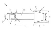
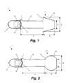
- FIG. 1is a cross-sectional illustration of a PDE including an engine forebody, inlets for air intake, fuel valves, engine ignition system, detonation chamber, and a conical diverging/converging nozzle attached to a cylindrical detonation chamber in accordance with one embodiment of the invention;
- FIG. 2is a cross-sectional illustration of a PDE having a spherical diverging/converging nozzle attached to a cylindrical detonation chamber in accordance with another embodiment of the invention.
- FIGS. 3A-3Cillustrate cross-sections for alternative geometry diverging/converging nozzles attached to cylindrical detonation chambers in accordance with alternative embodiments of the present invention.
- the efficiency of a pulsed detonation engineis improved though the use of a diverging-converging nozzle of predetermined geometric configuration.
- the pulsed detonation enginecomprises a detonation chamber for receiving a detonable mixture, an igniter for igniting the detonable mixture, and an outlet for discharging detonation products.
- the diverging-converging nozzlewhich can be made relatively short in length, enhances the performance and efficiency of the pulsed detonation engine.
- the present inventionis particularly useful for PDEs operating in air or other atmospheric environments.
- a pulsed detonation engine Ihas an engine forebody 5 , a detonation chamber 10 , and a converging diverging nozzle 11 .
- a set of electronically controlled fuel valves 3 a , 3 b within the forebody 5are provided for controlling flow of fuel injected into a flow of air, which is provided via one or more air inlets 2 .
- the fuel and airform a detonable mixture that fills the detonation chamber 10 .
- a suitable igniter 4such as a spark plug, laser, pyrotechnic device, etc., is provided in the detonation chamber 10 to ignite the detonable fuel/air mixture, producing detonation products.
- the detonation reactionproduces a brief period of extremely high temperature and high pressure inside the detonation chamber 10 . Typical detonation temperatures are on the order of 4000 K and pressures on the order of 20-40 atmospheres.
- the pulsed detonation engine 1comprises a generally cylindrical detonation chamber 10 having a length A of 10 cm and a diameter (width) of 2.5 cm.
- a generally conical, diverging-converging nozzle 11is attached at the aft of the detonation chamber 10 .
- the nozzle 11has a diverging portion 12 having a maximum diameter D which is greater than the diameter of the detonation chamber 10 , and a converging portion. 14 tapering to a minimum diameter C equal to the diameter of the detonation chamber 10 .
- the diverging converging nozzle 11 illustrated in FIG. 1has a maximum diameter D of 4.4 cm and a minimum diameter C of 2.5 cm.
- the diverging-converging nozzle 11 illustrated in FIG. 1has a length B of only 4.4 cm, the nozzle 11 yields comparable performance efficiency gains as would be realized by a 10 cm extension of the detonation chamber 10 .
- the particular dimensions of the diverging-converging nozzle 11may vary over a wide range depending on such factors as the dimensions of the detonation chamber 10 and the properties of the detonation products (e.g., particle size, velocity, etc.).
- the diverging-converging nozzle 11usually has a length B that is less than about 60% of the length of the detonation chamber A and preferably has a length that is less than about 50% of the length of the detonation chamber A.
- the diverging-converging nozzle 11should have a geometric shape capable of controllably expanding and accelerating the detonation products, e.g., without creating a negative impulse.
- cross-sections of the nozzle taken through planes perpendicular to the plane illustrated in FIGS. 1-3are circular, so that for any such cross-section, points along the internal surfaces of the nozzle 11 are equidistant from the longitudinal axis of the nozzle 11 .
- the term “diameter” as used hereinrefers to the diameter of such a circular cross-section, as well as to the minimum width or maximum width of a non-circular cross-section, in the context of minimum diameter and maximum diameter, respectively.
- the nozzle 11has maximum diameter D (diverging portion) that is greater than the width of the detonation chamber, and a minimum diameter C (converging portion) about equal to the diameter of the detonation chamber.
- Ddiverging portion
- Cconverging portion
- FIG. 2illustrates another embodiment of the present invention, in which a generally spherical diverging-converging nozzle 11 is employed.
- the detonation products discharged from the detonation chamber 10first expand into the diverging portion 22 of the nozzle, then are accelerated though the converging portion 24 of the nozzle 11 .
- the generally cylindrical detonation chamber 10 illustrated in FIG. 2has a length A of 10 cm and a diameter of 2.5 cm.
- the nozzle 11has a maximum diameter D of 4.4 cm, a minimum diameter C of 2.5 cm, and an overall length B of 4.4 cm.
- the device illustrated in FIG. 2exhibits comparable increased performance as would be realized by a device having a 10 cm linear extension of the detonation chamber 10 .
- FIGS. 3A-3Cillustrate alternative configurations for diverging-converging nozzles 11 .
- more complex geometric shapesalso may be used to enhance PDE performance in accordance with the present invention.
- detonation productsare discharged from the generally cylindrical detonation chamber 10 and first expand into the diverging portions 32 A, 32 B, 32 C of the respective nozzles 11 .
- the detonation productsthen are accelerated through the converging portions 34 A, 34 B, 34 C and discharged from the respective nozzles 11 .
- the diverging-converging nozzle 11 shown in FIG. 3Aincludes first B 1 , second B 2 , and third B 3 geometric portions, which are separated by vertical lines in FIG. 3A for purposes of illustration.
- the first portion B 1extends from the aft of the detonation chamber 10 .
- the cross-section of first portion B 1is curvilinear, beginning at about a right angle with respect to the longitudinal axis of the detonation chamber 10 and ending at an angle that is parallel to the longitudinal axis of the detonation chamber 10 .
- the end of the first portion B 1defines the maximum diameter D of the nozzle 11 .
- the second portion B 2 of constant diameterextends from the end of the first portion B 1 .
- the third portion B 3which extends from the end of the second portion B 2 , is generally conical and tapers from the maximum diameter D to a minimum diameter C.
- the diverging-converging nozzle 11 illustrated in FIG. 3Bhas a horseshoe-shaped cross-section.
- the nozzle 11includes a first portion B 4 extending from the detonation chamber 10 .
- the cross-section of first portion B 4is curvilinear, beginning at an obtuse angle with respect to the longitudinal axis of the detonation chamber 10 and ending at an angle that is parallel to the longitudinal axis of the detonation chamber 10 .
- the vertical lines inside of the nozzle 11 of FIG. 3Bare used to illustrate the changes in geometry.
- the region closest to the detonation chamber 10is less curved, while the region adjacent to the second portion B 5 is more curved.
- the end of the first portion B 4defines the maximum diameter D of the nozzle 11 .
- a second portion B 5gradually curves from the end of the first portion B 4 and tapers to a minimum diameter C.
- the diverging-converging nozzle 11 of FIG. 3Cincludes a first portion B 6 that extends from the detonation chamber 10 .
- the end of the first portion B 6defines the maximum diameter D of the nozzle 11 .
- the cross-section of the first portion B 6is curvilinear, beginning at an acute angle with respect to the longitudinal axis of the detonation chamber 10 and ending at an orientation that is parallel to the longitudinal axis of the detonation chamber 10 .
- a second, curvilinear portion B 7extends from the end of the first portion B 6 and gradually tapers to a minimum diameter C.
- a wide variety of fuelscan be used with the PDE of the present invention. Examples include fuels detonable in mixtures with air such as hydrogen, methane, propane, acetylene, or propylene. Also, detonable mixtures of liquid fuels and air can be used, e.g., kerosene/air, alcohol/air, benzene/air and other similar mixtures. Detonable monopropellants also can be used, such as nitromethane, nitroglycerin, or similar single-component fuels. Other useful fuels include aluminum (solid or vapor), magnesium (solid or vapor), carbon and boron. Although boron has ideal energy content, boron particles produced by a gas generator are usually coated with an oxide layer that must be removed before the boron will ignite.
- a fuel-rich gas based on aluminumcan be generated without an oxide layer.
- the aluminum particle sizeshould be kept below 10 microns to maintain a sustained detonation.
- Aluminumcan also be generated as a vapor, which will further enhance its detonability.
- Magnesiumcan be generated as a solid or vapor suspension, and can be detonated.
- the magnesium particles or dropletsshould be approximately 10 microns or less to detonate.
- Both aluminum and magnesium vapor suspensionshave very favorable detonation properties. However, an undesirable property of the vapor suspensions is their tendency to condense on cold surfaces because of the relatively high melting points of the two metals. Condensation of aluminum and magnesium vapor can cause mechanical problems if it occurs on tightly fitting parts with small gap tolerances.
- the systemcould be heated by designing a gas generator fuel grain that first produces hot gas followed by the fuel-rich gases.
- the fuel and airshould be thoroughly mixed to ensure the fuel concentration is within the detonability limit (i.e., near stoichiometric).
- the componentsshould be mixed to length scales comparable to the detonation phenomena length scales.
- Macroscopic mixingrefers to the bulk fluid processes, which bring the fuel and air components to close proximity (e.g., impingement of fuel and air streams).
- Microscopic mixingis the process by which the fuel and air are further mixed to a length scale required for detonation. Many techniques can be employed to produce microscopic mixing. However, care should be taken to minimize total pressure losses associated with these devices.
- One mixing strategyinvolves mixing the fuel and air in a separate pre-mixer before injection of the fuel and air into the detonative combustors.
- a primary problem related to pre-mixingis the potential of pre-ignition due to inadequate isolation of the mechanical elements of the engine.
- One variation of this strategyis to partially pre-mix the fuel and air to a fuel concentration level just outside the fuel-air mixture's detonability limits.
- Materials for construction of the engineshould be selected dependent on anticipated operating conditions. It is expected that the engine material could be exposed to peak temperatures approaching 4000 K and peak pressures of the order of about 20-40 atmospheres. Pressures just behind the detonation wave's shock front (i.e., in the ignition delay region) typically are of the order of about 40 atmospheres, and pressure ratios across the entire detonation region typically are of the order of about 20 atmospheres. The mode of operation will also expose the structure to periodic variations of both a thermal and a mechanical nature.
- Components made from carbon/carbon or titanium/zirconium/molybdenum (or similar alloy), both commercially available,may be used in construction of the PDE.
- the detonation chamber and diverging-converging nozzlecan each be manufactured from a carbon/carbon composite, optionally as a monolithic unit.
- Carbon/carboncan be machined to tolerances that produce surface finishes approaching the smoothness of machined metal.
- Carbon/carbonhas a very low thermal expansion coefficient and will allow the components of the engine to be assembled to very close tolerances, thus minimizing potential sealing problems.
- Titanium/zirconium/molybdenum materialsoffer high temperature capability and are easily machined.
- Detonationmay be initiated by igniting a fuel-oxygen mixture in a small detonation tube (not illustrated) that discharges into a detonation chamber 10 , or by igniting a fuel-oxygen mixture collocated within the detonation chamber 10 .
- a high voltage electric discharge or pyrotechnic ignitercan be used.
- the small detonation tube methodgenerally requires fuel, an oxidizer, pumps, high-speed fluid valves, an electronic controller, a power supply and a spark generator.
- the direct electric discharge methodgenerally requires a spark plug, an electronic controller and a power supply.
- Pyrotechnic ignitioninvolves a small solid rocket being fired systematically into the detonation chamber (e.g., through a small rotor or cylinder valve) to initiate detonation.
Landscapes
- Engineering & Computer Science (AREA)
- Chemical & Material Sciences (AREA)
- Combustion & Propulsion (AREA)
- Mechanical Engineering (AREA)
- General Engineering & Computer Science (AREA)
- Combustion Methods Of Internal-Combustion Engines (AREA)
Abstract
Description
Claims (18)
Priority Applications (1)
| Application Number | Priority Date | Filing Date | Title |
|---|---|---|---|
| US10/131,621US6662550B2 (en) | 2002-04-25 | 2002-04-25 | Method and apparatus for improving the efficiency of pulsed detonation engines |
Applications Claiming Priority (1)
| Application Number | Priority Date | Filing Date | Title |
|---|---|---|---|
| US10/131,621US6662550B2 (en) | 2002-04-25 | 2002-04-25 | Method and apparatus for improving the efficiency of pulsed detonation engines |
Publications (2)
| Publication Number | Publication Date |
|---|---|
| US20030200753A1 US20030200753A1 (en) | 2003-10-30 |
| US6662550B2true US6662550B2 (en) | 2003-12-16 |
Family
ID=29248606
Family Applications (1)
| Application Number | Title | Priority Date | Filing Date |
|---|---|---|---|
| US10/131,621Expired - LifetimeUS6662550B2 (en) | 2002-04-25 | 2002-04-25 | Method and apparatus for improving the efficiency of pulsed detonation engines |
Country Status (1)
| Country | Link |
|---|---|
| US (1) | US6662550B2 (en) |
Cited By (15)
| Publication number | Priority date | Publication date | Assignee | Title |
|---|---|---|---|---|
| US20060251821A1 (en)* | 2004-10-22 | 2006-11-09 | Science Applications International Corporation | Multi-sectioned pulsed detonation coating apparatus and method of using same |
| US20070186556A1 (en)* | 2006-02-13 | 2007-08-16 | General Electric Company | Methods and apparatus for operating a pulse detonation engine |
| US7735311B2 (en)* | 2003-12-09 | 2010-06-15 | Science Applications International Corporation | Pulsed detonation engines manufactured from materials having low thermal stability |
| CN103134081A (en)* | 2011-12-01 | 2013-06-05 | 通用电气公司 | Variable initiation location system for pulse detonation combustor |
| US9745807B2 (en) | 2006-08-23 | 2017-08-29 | M-I L.L.C. | Process for mixing wellbore fluids |
| US9920926B1 (en) | 2017-07-10 | 2018-03-20 | Thermochem Recovery International, Inc. | Pulse combustion heat exchanger system and method |
| US10099200B1 (en) | 2017-10-24 | 2018-10-16 | Thermochem Recovery International, Inc. | Liquid fuel production system having parallel product gas generation |
| US10214418B2 (en) | 2011-09-27 | 2019-02-26 | Thermochem Recovery International, Inc. | Method for converting biomass into fischer-tropsch products with carbon dioxide recycling |
| US10222060B2 (en) | 2016-02-16 | 2019-03-05 | Thermochem Recovery International, Inc. | Two-stage energy-integrated product gas generation system and method |
| US10286431B1 (en) | 2016-03-25 | 2019-05-14 | Thermochem Recovery International, Inc. | Three-stage energy-integrated product gas generation method |
| US10815440B2 (en) | 2010-11-05 | 2020-10-27 | Thermochem Recovery International, Inc. | Systems and methods for producing syngas from a solid carbon-containing substance using a reactor having hollow engineered particles |
| US11370982B2 (en) | 2016-08-30 | 2022-06-28 | Thermochem Recovery International, Inc. | Method of producing liquid fuel from carbonaceous feedstock through gasification and recycling of downstream products |
| US11466223B2 (en) | 2020-09-04 | 2022-10-11 | Thermochem Recovery International, Inc. | Two-stage syngas production with separate char and product gas inputs into the second stage |
| US11480136B1 (en)* | 2020-06-10 | 2022-10-25 | Richard D. Smith | Monopropellant continuous detonation engines |
| US11555157B2 (en) | 2020-03-10 | 2023-01-17 | Thermochem Recovery International, Inc. | System and method for liquid fuel production from carbonaceous materials using recycled conditioned syngas |
Families Citing this family (7)
| Publication number | Priority date | Publication date | Assignee | Title |
|---|---|---|---|---|
| US20110047962A1 (en)* | 2009-08-28 | 2011-03-03 | General Electric Company | Pulse detonation combustor configuration for deflagration to detonation transition enhancement |
| US8535491B2 (en)* | 2009-09-18 | 2013-09-17 | General Electric Company | Electrochemical machining assembly with curved electrode |
| CN102003303B (en)* | 2010-11-11 | 2013-04-17 | 西北工业大学 | Pulse detonation engine with secondary detonation |
| CN102003302A (en)* | 2010-11-18 | 2011-04-06 | 西北工业大学 | Air intake cone of air-breathing pulse detonation engine |
| CN102434317A (en)* | 2011-11-04 | 2012-05-02 | 西北工业大学 | Aspirating type combined pulse detonation engine with secondary detonation |
| US10060419B2 (en) | 2014-11-21 | 2018-08-28 | Northrop Grumman Systems Corporation | Battery powered vehicle propulsion system |
| JP6294924B2 (en)* | 2016-09-05 | 2018-03-14 | 株式会社Subaru | Vehicle travel control device |
Citations (6)
| Publication number | Priority date | Publication date | Assignee | Title |
|---|---|---|---|---|
| US2825202A (en)* | 1950-06-19 | 1958-03-04 | Snecma | Pipes traversed by pulsating flow gases |
| US3321920A (en)* | 1964-06-29 | 1967-05-30 | Brown Engineering Company Inc | Method of producing propulsive forces by intermittent explosions using gempolynitro and hydrazine compounds |
| US4741154A (en) | 1982-03-26 | 1988-05-03 | The United States Of America As Represented By The Secretary Of The Navy | Rotary detonation engine |
| US5345758A (en) | 1993-04-14 | 1994-09-13 | Adroit Systems, Inc. | Rotary valve multiple combustor pulse detonation engine |
| US5901550A (en) | 1993-04-14 | 1999-05-11 | Adroit Systems, Inc. | Liquid fueled pulse detonation engine with controller and inlet and exit valves |
| US6408614B1 (en)* | 1997-03-11 | 2002-06-25 | Dornier Medizintechnik Gmbh | High-power pressure wave source |
- 2002
- 2002-04-25USUS10/131,621patent/US6662550B2/ennot_activeExpired - Lifetime
Patent Citations (6)
| Publication number | Priority date | Publication date | Assignee | Title |
|---|---|---|---|---|
| US2825202A (en)* | 1950-06-19 | 1958-03-04 | Snecma | Pipes traversed by pulsating flow gases |
| US3321920A (en)* | 1964-06-29 | 1967-05-30 | Brown Engineering Company Inc | Method of producing propulsive forces by intermittent explosions using gempolynitro and hydrazine compounds |
| US4741154A (en) | 1982-03-26 | 1988-05-03 | The United States Of America As Represented By The Secretary Of The Navy | Rotary detonation engine |
| US5345758A (en) | 1993-04-14 | 1994-09-13 | Adroit Systems, Inc. | Rotary valve multiple combustor pulse detonation engine |
| US5901550A (en) | 1993-04-14 | 1999-05-11 | Adroit Systems, Inc. | Liquid fueled pulse detonation engine with controller and inlet and exit valves |
| US6408614B1 (en)* | 1997-03-11 | 2002-06-25 | Dornier Medizintechnik Gmbh | High-power pressure wave source |
Cited By (32)
| Publication number | Priority date | Publication date | Assignee | Title |
|---|---|---|---|---|
| US7735311B2 (en)* | 2003-12-09 | 2010-06-15 | Science Applications International Corporation | Pulsed detonation engines manufactured from materials having low thermal stability |
| US20060251821A1 (en)* | 2004-10-22 | 2006-11-09 | Science Applications International Corporation | Multi-sectioned pulsed detonation coating apparatus and method of using same |
| US20070186556A1 (en)* | 2006-02-13 | 2007-08-16 | General Electric Company | Methods and apparatus for operating a pulse detonation engine |
| US7836682B2 (en) | 2006-02-13 | 2010-11-23 | General Electric Company | Methods and apparatus for operating a pulse detonation engine |
| US9745807B2 (en) | 2006-08-23 | 2017-08-29 | M-I L.L.C. | Process for mixing wellbore fluids |
| US10815440B2 (en) | 2010-11-05 | 2020-10-27 | Thermochem Recovery International, Inc. | Systems and methods for producing syngas from a solid carbon-containing substance using a reactor having hollow engineered particles |
| US10800655B2 (en) | 2011-09-27 | 2020-10-13 | Thermochem Recovery International, Inc. | Conditioned syngas composition, method of making same and method of processing same to produce fuels and/or fischer-tropsch products |
| US11760631B2 (en) | 2011-09-27 | 2023-09-19 | Thermochem Recovery International, Inc. | Method of producing a cooled syngas of improved quality |
| US10214418B2 (en) | 2011-09-27 | 2019-02-26 | Thermochem Recovery International, Inc. | Method for converting biomass into fischer-tropsch products with carbon dioxide recycling |
| US10280081B2 (en) | 2011-09-27 | 2019-05-07 | Thermochem Recovery International, Inc. | Unconditioned syngas composition and method of cleaning up same for fischer-tropsch processing |
| US11186483B2 (en) | 2011-09-27 | 2021-11-30 | Thermochem Recovery International, Inc. | Method of producing sulfur-depleted syngas |
| US12077435B2 (en) | 2011-09-27 | 2024-09-03 | Thermochem Recovery International, Inc. | Method of generating clean syngas |
| CN103134081A (en)* | 2011-12-01 | 2013-06-05 | 通用电气公司 | Variable initiation location system for pulse detonation combustor |
| CN103134081B (en)* | 2011-12-01 | 2016-05-11 | 通用电气公司 | For the variable initiation position system of pulse detonation combustion device |
| US11242988B2 (en) | 2016-02-16 | 2022-02-08 | Thermochem Recovery International, Inc. | Two-stage energy-integrated product gas generation system and method |
| US10222060B2 (en) | 2016-02-16 | 2019-03-05 | Thermochem Recovery International, Inc. | Two-stage energy-integrated product gas generation system and method |
| US10287519B2 (en) | 2016-03-25 | 2019-05-14 | Thermochem Recovery International, Inc. | Three-stage energy-integrated product gas generation system |
| US10766059B2 (en) | 2016-03-25 | 2020-09-08 | Thermochem Recovery International, Inc. | System and method for recovering inert feedstock contaminants from municipal solid waste during gasification |
| US10946423B2 (en) | 2016-03-25 | 2021-03-16 | Thermochem Recovery International, Inc. | Particulate classification vessel having gas distributor valve for recovering contaminants from bed material |
| US10286431B1 (en) | 2016-03-25 | 2019-05-14 | Thermochem Recovery International, Inc. | Three-stage energy-integrated product gas generation method |
| US11634650B2 (en) | 2016-08-30 | 2023-04-25 | Thermochem Recovery International, Inc. | Method of producing liquid fuel from carbonaceous feedstock through gasification and recycling of downstream products |
| US11370982B2 (en) | 2016-08-30 | 2022-06-28 | Thermochem Recovery International, Inc. | Method of producing liquid fuel from carbonaceous feedstock through gasification and recycling of downstream products |
| US10215401B2 (en) | 2017-07-10 | 2019-02-26 | Thermochem Recovery International, Inc. | Pulse combustion heat exchanger system and method |
| US9920926B1 (en) | 2017-07-10 | 2018-03-20 | Thermochem Recovery International, Inc. | Pulse combustion heat exchanger system and method |
| US10099200B1 (en) | 2017-10-24 | 2018-10-16 | Thermochem Recovery International, Inc. | Liquid fuel production system having parallel product gas generation |
| US10350574B2 (en) | 2017-10-24 | 2019-07-16 | Thermochem Recovery International, Inc. | Method for producing a product gas having component gas ratio relationships |
| US11555157B2 (en) | 2020-03-10 | 2023-01-17 | Thermochem Recovery International, Inc. | System and method for liquid fuel production from carbonaceous materials using recycled conditioned syngas |
| US12187969B2 (en) | 2020-03-10 | 2025-01-07 | Thermochem Recovery International, Inc. | System and method for liquid fuel production from carbonaceous materials using recycled conditioned syngas |
| US11480136B1 (en)* | 2020-06-10 | 2022-10-25 | Richard D. Smith | Monopropellant continuous detonation engines |
| US11760949B2 (en) | 2020-09-04 | 2023-09-19 | Thermochem Recovery International, Inc. | Two-stage syngas production with separate char and product gas inputs into the second stage |
| US11466223B2 (en) | 2020-09-04 | 2022-10-11 | Thermochem Recovery International, Inc. | Two-stage syngas production with separate char and product gas inputs into the second stage |
| US12203040B2 (en) | 2020-09-04 | 2025-01-21 | Thermochem Recovery International, Inc. | Two-stage syngas production with separate char and product gas inputs into the second stage |
Also Published As
| Publication number | Publication date |
|---|---|
| US20030200753A1 (en) | 2003-10-30 |
Similar Documents
| Publication | Publication Date | Title |
|---|---|---|
| US6662550B2 (en) | Method and apparatus for improving the efficiency of pulsed detonation engines | |
| US5513489A (en) | Rotary valve multiple combustor pulse detonation engine | |
| US9476399B1 (en) | Glow plug type acoustic resonance igniter | |
| US6907724B2 (en) | Combined cycle engines incorporating swirl augmented combustion for reduced volume and weight and improved performance | |
| US7137255B2 (en) | Compact swirl augmented afterburners for gas turbine engines | |
| US7168236B2 (en) | Compact lightweight ramjet engines incorporating swirl augmented combustion with improved performance | |
| US6983586B2 (en) | Two-stage pulse detonation system | |
| US6820411B2 (en) | Compact, lightweight high-performance lift thruster incorporating swirl-augmented oxidizer/fuel injection, mixing and combustion | |
| US7669406B2 (en) | Compact, low pressure-drop shock-driven combustor and rocket booster, pulse detonation based supersonic propulsion system employing the same | |
| US7506498B2 (en) | Pulsed detonation engines for reaction control systems | |
| US20070180810A1 (en) | Pulse detonation combustor with folded flow path | |
| US20110047962A1 (en) | Pulse detonation combustor configuration for deflagration to detonation transition enhancement | |
| US7526912B2 (en) | Pulse detonation engines and components thereof | |
| US8966879B1 (en) | Acoustic igniter | |
| US5224344A (en) | Variable-cycle storable reactants engine | |
| Daniau et al. | Pulsed and rotating detonation propulsion systems: first step toward operational engines | |
| US6584761B2 (en) | MAPP gas fuel for flight vehicles having pulse detonation engines and method of use | |
| US7735311B2 (en) | Pulsed detonation engines manufactured from materials having low thermal stability | |
| US5131840A (en) | Combustion device for combustion of two fluid components | |
| US7690191B2 (en) | Fuel preconditioning for detonation combustion | |
| RU2315193C1 (en) | Ramjet engine with lengthwise heat-mass distribution | |
| Conrad | Exploring in aerospace rocketry. 7-Liquid propellant rocket systems |
Legal Events
| Date | Code | Title | Description |
|---|---|---|---|
| AS | Assignment | Owner name:SCIENCE APPLICATIONS INTERNATIONAL CORPORATION, CA Free format text:ASSIGNMENT OF ASSIGNORS INTEREST;ASSIGNORS:EIDELMAN, SHMUEL;CHAROVA, IRINA LEGAL REPRESENTATIVE OF DIMITRI CHAROV (DECEASED);REEL/FRAME:013338/0245;SIGNING DATES FROM 20020805 TO 20020926 | |
| AS | Assignment | Owner name:SCIENCE APPLICATIONS INTERNATIONAL CORPORATION, CA Free format text:CORRECTION OF ASSIGNMENT-REEL/FRAME 013338/0245 TO CORRECT THE ASSIGNOR;ASSIGNORS:EIDELMAN, SHMUEL;CHAROVA, IRINA, LEGAL REPRESENTATIVE OF DMITRI CHAROV;REEL/FRAME:014025/0213;SIGNING DATES FROM 20020805 TO 20020926 | |
| STCF | Information on status: patent grant | Free format text:PATENTED CASE | |
| FPAY | Fee payment | Year of fee payment:4 | |
| FPAY | Fee payment | Year of fee payment:8 | |
| AS | Assignment | Owner name:LEIDOS, INC., VIRGINIA Free format text:CHANGE OF NAME;ASSIGNOR:SCIENCE APPLICATIONS INTERNATIONAL CORPORATION;REEL/FRAME:032642/0452 Effective date:20130927 | |
| FPAY | Fee payment | Year of fee payment:12 | |
| AS | Assignment | Owner name:CITIBANK, N.A., DELAWARE Free format text:SECURITY INTEREST;ASSIGNOR:LEIDOS, INC.;REEL/FRAME:039809/0801 Effective date:20160816 Owner name:CITIBANK, N.A., DELAWARE Free format text:SECURITY INTEREST;ASSIGNOR:LEIDOS, INC.;REEL/FRAME:039818/0272 Effective date:20160816 | |
| AS | Assignment | Owner name:LEIDOS, INC., VIRGINIA Free format text:RELEASE BY SECURED PARTY;ASSIGNOR:CITIBANK, N.A., AS COLLATERAL AGENT;REEL/FRAME:051632/0819 Effective date:20200117 Owner name:LEIDOS, INC., VIRGINIA Free format text:RELEASE BY SECURED PARTY;ASSIGNOR:CITIBANK, N.A., AS COLLATERAL AGENT;REEL/FRAME:051632/0742 Effective date:20200117 |