US6662254B1 - System architecture - Google Patents
System architectureDownload PDFInfo
- Publication number
- US6662254B1 US6662254B1US09/599,797US59979700AUS6662254B1US 6662254 B1US6662254 B1US 6662254B1US 59979700 AUS59979700 AUS 59979700AUS 6662254 B1US6662254 B1US 6662254B1
- Authority
- US
- United States
- Prior art keywords
- bus
- backplane
- pci
- bridge
- card
- Prior art date
- Legal status (The legal status is an assumption and is not a legal conclusion. Google has not performed a legal analysis and makes no representation as to the accuracy of the status listed.)
- Expired - Fee Related, expires
Links
Images


Classifications
- G—PHYSICS
- G06—COMPUTING OR CALCULATING; COUNTING
- G06F—ELECTRIC DIGITAL DATA PROCESSING
- G06F13/00—Interconnection of, or transfer of information or other signals between, memories, input/output devices or central processing units
- G06F13/38—Information transfer, e.g. on bus
- G06F13/40—Bus structure
- G06F13/4004—Coupling between buses
- G06F13/4027—Coupling between buses using bus bridges
- G06F13/4045—Coupling between buses using bus bridges where the bus bridge performs an extender function
Definitions
- the present inventionrelates generally to the field of communication devices. More specifically, the present invention is related to high capacity computer-based telecommunication devices.
- auxiliary telecom bussesare incorporated into high capacity computer-based telecommunications equipment and typically transport N ⁇ 64 Kbps low-latency communications traffic between the cards of the system, independently from the computer's I/O and memory busses.
- One such busis defined by the Enterprise Computer Telephony Forum and is designated as H.110.
- H.110is a TDM based bus providing up to 4096 time slots at 8 MHz for voice and/or data communications.
- This bushas been targeted to CompactPCI (cPCI) form factor products.
- cPCICompactPCI
- CompactPCIis a standard laid forth by the PCI Industrial Manufacturers Group (PICMG) which specifies an electrical superset of desktop PCI utilizing a form factor suitable for rugged applications (e.g. industrial computers).
- the form factor of cPCIis based upon the Eurocard form factor popularized by the VME bus.
- CompactPCIutilizes 2 mm metric pin and socket connectors with cPCI cards inserted from the front of the chassis with I/O breakout either to the front or rear.
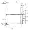
- FIG. 1The form factor for cPCI cards is illustrated in FIG. 1 .
- CompactPCI standardsupports both 3 U 100 (100 mm by 160 mm) and 6 U 102 (233.35 mm by 160 mm) card sizes.
- the rear card connectorsare designated J 1 -J 5 (or P 1 -P 5 ) 104 - 112 , in the PICMG specification, starting from the bottom of the card.
- 3 U 100 cPCI cardsutilize both J 1 104 and J 2 106 providing 220 pins for power, ground and all 32 bit and 64 bit PCI signals.
- the J 1 104 (or P 1 )is 110 pins and the J 2 106 (or P 2 ) is 110 pins.
- the card connectorsare female connectors and the backplane connectors are male connectors.
- the 3 U form factoris the minimum for cPCI supporting 64 bit transfers, however, cards which are to only perform 32 bit transfers can utilize only the lower connector J 1 104 .
- 6 U 102 extensionsare defined for cards where extra card area or connection space is needed.
- the use of the remaining connectors J 3 108 , J 4 110 , and J 5 112are designated in the specification as capable of being user designed for specific applications.
- a cPCI systemis composed of one or more cPCI bus segments. Each segment comprises up to eight (eight being the limitation due to electrical load considerations) card locations at 33 MHz.
- a typical cPCI backplane utilizing a single cPCI segment 200is illustrated in FIG. 2 .
- the cPCI backplanecomprises the male J 1 202 and J 2 204 (only numbered for slot 8 206 for clarity) connectors for each of the card locations/slots 206 - 220 .
- Each cPCI segmentcomprises a system slot 220 and up to seven peripheral slots 206 - 218 .
- the system slot card(system card) provides arbitration, clock distribution and reset functions for the other cards on the segment.
- the system slot cardis also manages each local card's IDSEL signal in order to perform system initialization.
- the PICMGdefines a means for cPCI system cards to drive two independent PCI bus segments in a 6 U environment. This is illustrated in FIG. 3 .
- System card 300is constructed to the 6 U form factor with the first PCI segment/bus connected to connectors J 1 302 and J 2 304 .
- the second PCI segment/busis connected to the card via connectors J 4 306 and J 5 308 .
- the first busis referred to the PCI bus A or PCI bus B while the second bus is designated as the PCI bus C.
- System card 300utilizes PCI bridge chips 310 , 312 and an on card PCI bus to bridge between the first segment and the second segment.
- one of the advantages to implementing a system utilizing a 6 U form factoris to support extra features for an industrial system.
- the industrial computer systemis designed for computer telephony applications.
- Two important specifications related to the implementation of a telecom bus in a cPCI chassisare the PICMG 2.5 Computer Telephony specification and the ECTF H.110 (CT) bus specifications.
- CTECTF H.110
- the specificationsmake use of the J 4 connector and, therefore, the J 4 connector is a precious connector for telecommunication equipment manufacturers.
- the PICMG architecture for bridging between two PCI segmentscreates a wasteful use of the J 4 /J 5 connectors and further prevents the addition of a second telecom bus such as the H.110.
- the system architecture of the present inventionallows for the creation of a high capacity computer-based device which can handle a number of communication protocols.
- the Internet, or IP based networks in generalhave become an important part of the current communications infrastructure.
- the present invention's unique architectureis utilized to provide a device which combines traditional IP routing capabilities with a gateway for non-IP traffic to the IP network.
- the IP routing meansthat the device can receive IP datagrams from one IP network and forward it to the correct destination, according to the destination IP address within the datagram.
- a voice gatewayfor example, the device uses its own IP address to represent the non-IP voice channels on the IP network. To separate the incoming IP datagrams to their specific voice channel, there's a need to identify each voice flow. Since all those flows use the device IP as destination address, there's a need to look at higher layer parameters to identify a flow.
- Voice streamsfor example, use TCP and RTP as transport layers. Each voice flow is identified by a unique ⁇ source IP, source UDP port, destination IP, destination UDP port>combination.
- IP routinginvolves mapping of the 32 bits of the IP address to a correct destination (traditional routing operation). Since there are 2 32 different IP address, it's not practical to use a lookup table that stores the destination information, where the IP address is the entry index to this lookup table. In order to solve this mapping problem, there's a need to employ more sophisticated hashing and caching algorithms. The problem is further complicated when dealing with locally designated IP data flows (flows whose destination IP address is the local IP address of the device). These are used when the device is working as a gateway from IP to non-IP traffic.
- IP routingtypically involves routing only at layer 3 (by mapping the IP address as described above).
- a traditional routerdoes not look at the layer 4 and above protocols to determine a destination. Datagrams are simply encapsulated in a MAC frame and forwarded to the destination device. It is the responsibility of the layer 4 and above protocols at the destination device to properly identify the unique flow (typically based upon the IP destination and source address and the TCP/UDP source and destination address). This requires additional overhead on the destination device's layer 4 and above software/hardware, as it has to decode the layer 3 , 4 and above headers in order to identify the data flow.
- IP datais packet based
- busses which follow packet based standardsare advantageous to utilize in the transmission of IP datagrams.
- One such setis so called LANs based upon IEEE 802 standards.
- the IEEE 802 standardsspecify the layer 1 and layer 2 protocols.
- One of the most commonly utilized standardsis the IEEE 802.3 (Ethernet and Fast Ethernet), and more recently the IEEE 802.3 z (Gigabit Ethernet), all based upon a CSMA/CD medium access control technique.
- bussesmay be arranged in a number of topologies.
- One such topologyis the star topology.
- each device connected to the busis connected directly to a common central node utilizing point-to-point connections.
- Other commonly utilized topologiesinclude bus, tree, and ring.
- the backplane of the present inventionis an enhance backplane supporting a plurality of busses working independently of each other and each utilized for a different data type.
- the backplanesupports at least one peripheral connection bus (I/O bus), at least one telecom bus, and at least one network bus.
- the systemprovides for the scalability of the peripheral connection bus through bridging between two peripheral connection busses.
- a first serializeroperatively connected to the first peripheral bus, is used to receive data from a first peripheral connection bus, serializes the data, and transfers the serial data stream to a second serializer which is operatively coupled to the second bus.
- the second serializerde-serializes the transferred data and transfers it to the second peripheral connection bus.
- the backplaneis utilized with a router and I/O cards to provide a device which combines traditional IP routing capabilities with a gateway for non-IP traffic to the IP network.
- a unique routing methodis utilized to reduce the overhead associated with identifying data flows at the I/O card.
- the routerreceives the incoming datagrams and looks at the layer 3 and above headers to determine which I/O card to send the data to and to identify the data flow.
- the routerthen encapsulates the data into a specialized frame which designates the I/O card and uniquely identifies the data flow and forwards this over the network bus to the appropriate card.
- the carddetermines the destination of the data via the specialized frame without having to look at the layer 3 and above headers.
- FIG. 1illustrates the form factor for cPCI cards.
- FIG. 2illustrates a typical cPCI backplane utilizing a single cPCI segment.
- FIG. 3illustrates the PICMG method for cPCI system cards to drive two independent PCI bus segments.
- FIG. 4illustrates the general architecture of a device according to the present invention.
- FIG. 5illustrates a block diagram of a card equipped to perform the serial bridging between the cPCI segment.
- FIG. 6illustrates a general block diagram of the PCI serializer/deserializer.
- FIG. 7illustrates a more detailed view of the PCI serializer/deserializer.
- FIG. 8illustrates cPCI segment bridging with redundancy.
- FIG. 9illustrates a standard MAC address structure and the internal MAC address structure of the device of the present invention.
- FIG. 10illustrates the data flow between the router card to I/O card for both locally and remotely designated IP flows.
- FIG. 11illustrates the data flow from the I/O card to router card, for both locally and remotely designated IP flows.
- FIG. 4illustrates the general architecture of a device according to the present invention.
- the computer systemincludes a chassis, which hosts a passive backplane which interconnects different types of system and interface modules.
- the system and interface modulesinclude power supply module(s) 408 , central processing module(s) 406 , network interface module(s) 404 , and Input/Output (I/O) module(s) 402 .
- Power supply module(s) 408are standard cPCI 3 U power supplies.
- Central Processing module(s) 406is responsible for managing the system configuration, monitoring the status of the system and arbitrating the bus. At times it is preferable to provide more than one central processing module 406 in order to provide a master/standby configuration for redundancy.
- Backplane 424is an enhanced cPCI compatible backplane which includes the standard 2 mm connectors. As previously described, a cPCI compatible bus supporting 6 U system cards includes 5 connectors per slot.
- the novel backplane of the systemcomprises a number of busses.
- the PCI bus 410is a standard 32/64 bit cPCI bus. There are 2 cPCI segments, bridged in a unique fashion via a serial bus, working at 33 MHz and supporting 8 slots each.
- PCI bus 410is implemented in the J 1 /J 2 connectors according to the cPCI standard. This bus is the I/O bus for the system and is used for signaling and control communication between the modules of the system.
- H.110 busses 414located on the backplane. The first of these is a standard H.110 bus implemented in the J 4 connector, according to the standard. The second is a full H.110 bus implemented in the J 3 connector in a proprietary way. These busses are utilized for transferring real time digital T 1 /E 1 telephony between the modules of the system. These busses support 2*4096 time slots, or 128 T 1 /E 1 's. The architecture supports full non-blocking cross connect for 256 T 1 /E 1 lines.
- the communication bus 412is a serial shared bus connecting all modules in the system. This bus is working at 10 MHz and implements an HDLC shared communication. Communication bus 412 is used for control information and as a redundant path for signaling information.
- the network bus 426is a StarLan bus (star topology) which provides a collection of high speed point to point connections between the network module(s) 404 and all other modules of the system. This bus is used with redundancy when two network modules 404 are installed. Each connection is working at 100 Mb/s (FETH) or 1000 Mb/s (GETH). StarLan bus 426 transfers IP information from the I/O module(s) and central processing module(s) to the, main link interface 404 .
- StarLan bus 426transfers IP information from the I/O module(s) and central processing module(s) to the, main link interface 404 .
- Power bus 416transfers power from power supply module(s) 408 , which receive power via power inlet 418 , to all the modules in the system. This bus is implemented utilizing the standard cPCI pins.
- Each moduleis connected to its respective interface (IM) card(s) 422 via the J 5 connector on the backplane.
- the IM card(s) 422provide the interface and physical connector which connects the respective module to the “outside” world (externally of the system).
- the use of the IM cardsenable replacement of the system modules without the need to disconnect any cables.
- the backplane(through J 5 ) support 16 T 1 /E 1 interfaces, 4 T 3 /E 3 interfaces, 2 STM 1 interfaces and up to 8 Ethernet interfaces.
- the backplanesupports 2 STM 1 /4 interfaces, 2 GbEth interfaces and up to 8 Ethernet interfaces.
- a PCI serializertransparently transceives PCI frames across the cPCI backplane.
- spare pinsare available for the serial-bridging channel to be located in the J 1 /J 2 connectors
- J 3is used to provide compatibility with current PICMG specification for the PCI connectors. This provides for a preferred embodiment feature of maintaining the availability of the J 4 /J 5 connectors.
- FIG. 5demonstrates a block diagram of a card equipped to perform the bridging between the cPCI segments. Preferably, this is implemented in the system card, however, a separate card may be utilized.
- System card 500has a PCI-PCI bridge chip 502 located thereon.
- Bridge chip 502is connected to the PCI bus via connectors J 1 504 and J 2 506 .
- An oncard PCI busconnects the bridge chip to PCI serializer/deserializer 508 which serializes the data and sends it to the second cPCI segment where an I/O card has a deserializer and a second bridge to place the data on the second PCI bus located on the second segment.
- the serial busis connected to the serializer 508 and deserializer via the J 3 connector.
- the serial communicationutilizes Low Voltage Differential Signaling (LVDS) so that only two pins per pair are required and a common ground between the two segments is not needed.
- LVDSLow Voltage Differential Signaling
- FIG. 6illustrates a general block diagram of the PCI serializer/deserializer located on the appropriate cards of each segment.
- PCI Serializer 600is comprised of three main blocks.
- a PCI master/target block 602which interfaces to the PCI bus.
- a framer 604orders the PCI frames.
- a high speed serializer/deserializer 606serializers the data and transfers it across the serial channel.
- the serial channelprovides a bandwidth that will not hinder the eight slot per segment cPCI bus.
- the serial channelis built out of 4 full duplex pairs, each providing 622 mbps of bandwidth.
- Current cPCI technologyenables an eight-segment cPCI bus to operate 64 bit at 33 MHz which is a bandwidth of 2 Gbit/s. Subsequently, the PCI front end of the serializer must sustain this bandwidth and operate at either 64 bit/33 MHz or a more efficient PCI Local bus topology of 32 bit/66 MHz.
- FIG. 7provides a more detailed view of the PCI serializer/deserializer.
- the serial streamis deserialized and passed through the framer 706 .
- Rx DMA control logic 704synchronizes between the framer and the PCI Master/Target core 702 which interfaces to the Local/oncard PCI bus.
- the PCI Local Bus-to-Compact PCI bridgehandshakes with the serializer 700 to enable or disable frame flow.
- Serial interface 708is based on mature LVDS technology, which is widely used for high-speed serial links.
- FIG. 8illustrates this system architecture.
- Segment bridgingis provided when a system card 810 in segment A 802 is bridged to an I/O card 812 containing a PCI serializer on segment B 804 . Redundancy is achieved when an additional system card 808 on segment B 804 functions in a slave mode (is not the system host) and is bridged to an I/O card 806 containing a PCI serializer on segment A 802 . In the case that redundancy is not supported, the bridge between the two segments is done between the two system cards 810 and I/O card 812 on the two segments.
- This redundancy architectureproposes a system host Master and Slave cards. Arbitration and clock distribution are handled on a per segment basis. For example, host Master 810 on segment A 802 provides clock distribution and PCI bus arbitration for segment A 802 with its consociate I/O 812 card linked via the serial channel providing the clock distribution and PCI arbitration services on segment B 804 . After a redundant switchover, the Master 808 on segment B 804 provides the clock distribution and PCI arbitration services on segment B 804 while the I/O card 806 on segment A 802 , linked via the serial channel, provides the clock distribution and PCI arbitration services for segment A.
- Additional lines or a dedicated communication channelmay be implemented to synchronize between the Master and Slave host cards in order to provide application redundancy.
- the unique architectureis utilized to provide a device which combines traditional IP routing capabilities with a gateway for non-IP traffic to the IP network. As previously described, there are difficulties associated with the routing of the data.
- Local designated data flowsare flows whose destination IP address is the local IP address of the device.
- source IP address32 bits
- additional fields in the upper layersFor example, both UDP and TCP flows are defined by a source IP address, source UDP/TCP port, destination IP address and destination UDP/TCP port.
- source IP address32 bits
- TCP/TCP porta source IP address
- destination IP address32 bits
- destination UDP/TCP porta source IP address
- destination IP address32 bits
- UDP/TCP portdestination IP address
- destination UDP/TCP portTo differentiate the UDP from TCP and other protocols, there's a need to look at another field that contains the protocol identifier. Therefore, when we want to identify a certain UDP flow, for example, we have to map 72 bits (32 bits of source IP+8 protocol ID+16*2 for source and destination UDP ports) to the correct destination.
- One embodiment of the present inventionutilizes the unique architecture of FIG. 4 to combine traditional IP routing with a gateway for non-IP traffic to IP networks. It comprises one central IP routing and flow identifier switching module (router module) and I/O modules.
- the connection between each I/O module and the router moduleis done via internal 100/1000 Ethernet connections/network bus on the backplane.
- the router moduleis responsible to do the entire layer 3 and above handling. It uses special ASIC chips, like network processors, to do it at full wire speed.
- the I/O modulehandles only the link layer of the different protocols that are attached to it and the encapsulation—de-encapsulation of protocols.
- the I/O carddoesn't have to look and/or switch according to the IP layer and the upper layers parameters of the traffic.
- FIG. 9illustrates a standard MAC address structure 900 and the internal MAC address structure of the device 902 .
- the LSBs of the internal address structure 902are utilized as a destination identifier (flow identifier), while the MSBs remain constant for a given device.
- the number of bits utilized for the flow identifieris dependent upon the number of destinations located within the device, and are therefore, a parameter which is based upon the design of the device.
- a MAC address from this internal MAC rangeis assigned to any destination inside the device (where the destination is a certain entity in one of the I/O cards).
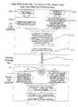
- FIGS. 10 and 11illustrate the data flow between the router card to I/O card and I/O card to router card, respectively, for both locally and remotely designated IP flows; to be described hereafter:
- Any IP datagram whose destination IP address is the device addressis a locally designated datagram.
- the deviceis the IP endpoint of such flows.
- a different entity on one of the I/O cardsmay serve each such flow (for example a certain software instance that handles a specific voice channel on one of the I/O cards).
- the router cardOn the downstream direction (from router card to the I/O card), when the device receives a local flow datagram, the router card is responsible to identify the local flow according to the layer 3 , 4 and even higher layer parameters 1002 , 1004 , 1006 b . After identifying the flow, the router card maps it to a MAC address that is associated with this flow 1006 b . The IP flow is then encapsulated in an Ethernet frame where this MAC address is used as destination MAC address 1008 . The data on layer 3 and above is unaltered by the router card. The datagram is then forwarded by the router card to the correct Ethernet bus (and therefore to the correct I/O card) as part of regular layer 2 switching process 1010 , 1012 .
- the I/O cardWhen the I/O card receives the datagram from the internal Ethernet bus, it uses the flow id from the MAC address as an index to a lookup table to find the destination server software (a certain software entity) that processes this flow 1014 , 1016 .
- This software entitydoes not look at the transport headers (e.g. IP and UDP or IP and TCP etc.). It can remove the IP transport headers to handle the data at the application level 1018 .
- the router cardOn the upstream side (from I/O to router card), before one of the entities of the I/O card (voice channel for example) sends data to the router card, it first encapsulates the application data with IP transport headers 1104 a . Then it encapsulates this IP datagram over Ethernet 1106 .
- the destination MAC address of this frameis the internal MAC address of the router.
- the source MAC of this Ethernet frameis the MAC address that was assigned to this entity 1106 .
- the frameis now sent over the internal Ethernet bus to the router card 1108 .
- the router cardforwards this datagram according to its destination IP address. If the destination address is the device IP then it's again treated as local designated flow, otherwise, it's handled as external flow.
- Any IP datagram whose destination IP address is not the same as the device addressis considered a remote IP flow.
- An internal MAC address from the continuous MAC rangeis assigned to each IP interface on every I/O card.
- the router cardreceives an external flow 1002 , 1004 , 1006 a , 1008 it uses its IP routing table to map the destination IP address to a next hop MAC address 1006 a .
- the datagramis then forward by the router card to the correct Ethernet bus (and therefore to the correct I/O card) as part of regular layer 2 switching process 1010 .
- the I/O cardWhen the I/O card receives the datagram from the internal Ethernet bus, it uses the flow id from the destination MAC address as an index to a lookup table 1014 , 1016 to match the IP interface that this datagram should be forwarded through 1018 . Now the I/O card removes the Ethernet header and encapsulates the IP datagram over the network layer that this IP interface uses (e.g. frame relay, PPP, etc.).
- the network layere.g. frame relay, PPP, etc.
- one of the IP interfacesreceives data 1100 b , it first removes the layer 2 headers 1104 b (e.g. if it's IP over Frame Relay, it removes the RFC1490 and the Frame Relay headers); then it encapsulates the IP datagram over Ethernet with the internal MAC address of the router card as the destination MAC address.
- the source MAC of this Ethernet frameis the MAC address that belongs to the IP interface 1106 .
- the router cardforwards this datagram according to its destination IP address. If the destination address is the device IP, then it's again treated as local designated flow, otherwise, it's handled as external flow.
Landscapes
- Engineering & Computer Science (AREA)
- General Engineering & Computer Science (AREA)
- Theoretical Computer Science (AREA)
- Computer Hardware Design (AREA)
- Physics & Mathematics (AREA)
- General Physics & Mathematics (AREA)
- Data Exchanges In Wide-Area Networks (AREA)
Abstract
Description
Claims (28)
Priority Applications (1)
| Application Number | Priority Date | Filing Date | Title |
|---|---|---|---|
| US09/599,797US6662254B1 (en) | 2000-06-22 | 2000-06-22 | System architecture |
Applications Claiming Priority (1)
| Application Number | Priority Date | Filing Date | Title |
|---|---|---|---|
| US09/599,797US6662254B1 (en) | 2000-06-22 | 2000-06-22 | System architecture |
Publications (1)
| Publication Number | Publication Date |
|---|---|
| US6662254B1true US6662254B1 (en) | 2003-12-09 |
Family
ID=29712473
Family Applications (1)
| Application Number | Title | Priority Date | Filing Date |
|---|---|---|---|
| US09/599,797Expired - Fee RelatedUS6662254B1 (en) | 2000-06-22 | 2000-06-22 | System architecture |
Country Status (1)
| Country | Link |
|---|---|
| US (1) | US6662254B1 (en) |
Cited By (52)
| Publication number | Priority date | Publication date | Assignee | Title |
|---|---|---|---|---|
| US20020161929A1 (en)* | 2001-04-30 | 2002-10-31 | Longerbeam Donald A. | Method and apparatus for routing data through a computer network |
| US20020194413A1 (en)* | 2001-06-15 | 2002-12-19 | Seto Stephen C. | CompactPCI hotswap automatic insertion/extraction test equipment |
| US20030065869A1 (en)* | 2001-10-01 | 2003-04-03 | Francois Balay | PCI/LVDS half bridge |
| US20030067915A1 (en)* | 2001-10-04 | 2003-04-10 | Alcatel | Network nodes |
| US20030076778A1 (en)* | 2001-10-23 | 2003-04-24 | Lg Electronics Inc. | Duplication apparatus of cPCI system |
| US20030221019A1 (en)* | 2002-05-24 | 2003-11-27 | Fussell Andrew M. | Media bus interface arbitration for a data server |
| US20040073834A1 (en)* | 2002-10-10 | 2004-04-15 | Kermaani Kaamel M. | System and method for expanding the management redundancy of computer systems |
| US20040073833A1 (en)* | 2002-10-10 | 2004-04-15 | Sun Microsystems, Inc. | Apparatus and methods for redundant management of computer systems |
| US20040172494A1 (en)* | 2003-01-21 | 2004-09-02 | Nextio Inc. | Method and apparatus for shared I/O in a load/store fabric |
| US20040179534A1 (en)* | 2003-01-21 | 2004-09-16 | Nextio Inc. | Method and apparatus for shared I/O in a load/store fabric |
| US20040210700A1 (en)* | 2003-04-16 | 2004-10-21 | Hill Charles C. | Compact PCI backplane and method of data transfer across the compact PCI backplane |
| US20040221084A1 (en)* | 2003-04-30 | 2004-11-04 | Hewlett-Packard Development Company, L.P. | Form factor converter and tester in an open architecture modular computing system |
| US20040260842A1 (en)* | 2003-04-18 | 2004-12-23 | Nextio Inc. | Switching apparatus and method for providing shared I/O within a load-store fabric |
| US20050025119A1 (en)* | 2003-01-21 | 2005-02-03 | Nextio Inc. | Switching apparatus and method for providing shared I/O within a load-store fabric |
| US20050027900A1 (en)* | 2003-04-18 | 2005-02-03 | Nextio Inc. | Method and apparatus for a shared I/O serial ATA controller |
| US6963909B1 (en)* | 2001-07-24 | 2005-11-08 | Cisco Technology, Inc. | Controlling the response domain of a bootP/DHCP server by using network physical topology information |
| US20060062227A1 (en)* | 2004-09-23 | 2006-03-23 | Tufford Robert C | Switched fabric payload module having an embedded central switching resource |
| US20060062226A1 (en)* | 2004-09-23 | 2006-03-23 | Harris Jeffrey M | Switched fabric rear transition module and method |
| US20060072545A1 (en)* | 2004-09-23 | 2006-04-06 | Tufford Robert C | Multi-network modules with hot-swap capability |
| US7039073B1 (en)* | 2001-02-22 | 2006-05-02 | Cisco Technology, Inc. | Bound mode technique for accommodating high-bandwidth data flow within an intermediate network node |
| US7046668B2 (en) | 2003-01-21 | 2006-05-16 | Pettey Christopher J | Method and apparatus for shared I/O in a load/store fabric |
| US20060109845A1 (en)* | 2004-11-23 | 2006-05-25 | Sandy Douglas L | Method of transporting a RapidIO packet over an IP packet network |
| US20060112211A1 (en)* | 2004-11-23 | 2006-05-25 | Sandy Douglas L | Method of transporting a PCI express packet over a VMEbus network |
| US20060112186A1 (en)* | 2004-11-23 | 2006-05-25 | Sandy Douglas L | Method of communicating a VMEbus signal over IP packet network |
| US7062594B1 (en)* | 2004-06-30 | 2006-06-13 | Emc Corporation | Root complex connection system |
| US7088737B1 (en)* | 2000-10-27 | 2006-08-08 | Redback Networks Inc. | Method and apparatus for combining packets having different protocol encapsulations within a circuit |
| US20060220464A1 (en)* | 2005-03-30 | 2006-10-05 | Hanahan Bruce A | Highly available power distribution system |
| US7136290B1 (en)* | 2006-05-31 | 2006-11-14 | Motorola, Inc. | Blade circuit cross-connection adapted for peer-to-peer backplanes |
| US7174413B2 (en) | 2003-01-21 | 2007-02-06 | Nextio Inc. | Switching apparatus and method for providing shared I/O within a load-store fabric |
| US20080186213A1 (en)* | 2007-02-02 | 2008-08-07 | Neil Sharma | Mechanism for channel synchronization |
| US20080192740A1 (en)* | 2005-03-04 | 2008-08-14 | Nokia Siemens Networks Gmbh & Co. Kg | Processing Realtime Media Streams |
| US20080307149A1 (en)* | 2007-06-08 | 2008-12-11 | Tomonori Hirai | Clustering System and Flexible Interconnection Architecture Thereof |
| US7489867B1 (en)* | 2002-05-06 | 2009-02-10 | Cisco Technology, Inc. | VoIP service over an ethernet network carried by a DWDM optical supervisory channel |
| US7493416B2 (en) | 2003-01-21 | 2009-02-17 | Nextio Inc. | Fibre channel controller shareable by a plurality of operating system domains within a load-store architecture |
| US7502370B2 (en) | 2003-01-21 | 2009-03-10 | Nextio Inc. | Network controller for obtaining a plurality of network port identifiers in response to load-store transactions from a corresponding plurality of operating system domains within a load-store architecture |
| US20090083471A1 (en)* | 2007-09-20 | 2009-03-26 | Bradly George Frey | Method and apparatus for providing accelerator support in a bus protocol |
| US7512717B2 (en) | 2003-01-21 | 2009-03-31 | Nextio Inc. | Fibre channel controller shareable by a plurality of operating system domains within a load-store architecture |
| US7617333B2 (en) | 2003-01-21 | 2009-11-10 | Nextio Inc. | Fibre channel controller shareable by a plurality of operating system domains within a load-store architecture |
| US7698483B2 (en) | 2003-01-21 | 2010-04-13 | Nextio, Inc. | Switching apparatus and method for link initialization in a shared I/O environment |
| US20100161870A1 (en)* | 2008-12-24 | 2010-06-24 | Daniel David A | Virtualized PCI endpoint for extended systems |
| US7836211B2 (en) | 2003-01-21 | 2010-11-16 | Emulex Design And Manufacturing Corporation | Shared input/output load-store architecture |
| US20110022754A1 (en)* | 2007-12-06 | 2011-01-27 | Technion Research & Development Foundation Ltd | Bus enhanced network on chip |
| US7917658B2 (en) | 2003-01-21 | 2011-03-29 | Emulex Design And Manufacturing Corporation | Switching apparatus and method for link initialization in a shared I/O environment |
| US7953074B2 (en) | 2003-01-21 | 2011-05-31 | Emulex Design And Manufacturing Corporation | Apparatus and method for port polarity initialization in a shared I/O device |
| US20110228783A1 (en)* | 2010-03-19 | 2011-09-22 | International Business Machines Corporation | Implementing ordered and reliable transfer of packets while spraying packets over multiple links |
| US8032659B2 (en) | 2003-01-21 | 2011-10-04 | Nextio Inc. | Method and apparatus for a shared I/O network interface controller |
| US8102843B2 (en) | 2003-01-21 | 2012-01-24 | Emulex Design And Manufacturing Corporation | Switching apparatus and method for providing shared I/O within a load-store fabric |
| US8346884B2 (en) | 2003-01-21 | 2013-01-01 | Nextio Inc. | Method and apparatus for a shared I/O network interface controller |
| CN102935849A (en)* | 2012-09-29 | 2013-02-20 | 南京恩瑞特实业有限公司 | Redundancy input and output achievement system of vehicle-mounted signal equipment |
| US20170344451A1 (en)* | 2016-05-31 | 2017-11-30 | Bristol, Inc. | Methods and apparatus to communicatively couple field devices to a remote terminal unit |
| US20170344445A1 (en)* | 2016-05-31 | 2017-11-30 | Bristol, Inc. D/B/A Remote Automation Solutions | Methods and apparatus to implement communications via a remote terminal unit |
| US10289572B2 (en)* | 2016-10-14 | 2019-05-14 | General Electric Company | Industrial control adjacent input-output modules and methods thereof |
Citations (16)
| Publication number | Priority date | Publication date | Assignee | Title |
|---|---|---|---|---|
| US4937777A (en) | 1987-10-07 | 1990-06-26 | Allen-Bradley Company, Inc. | Programmable controller with multiple task processors |
| US5038317A (en) | 1988-07-25 | 1991-08-06 | Allen-Bradley Company, Inc. | Programmable controller module rack with a relative rack slot addressing mechanism |
| US5530842A (en) | 1990-04-23 | 1996-06-25 | 3Com Corporation | Generic backplane system which is configurable to serve different network access methods simultaneously |
| US5544162A (en) | 1995-01-10 | 1996-08-06 | International Business Machines Corporation | IP bridge for parallel machines |
| US5764924A (en)* | 1995-08-24 | 1998-06-09 | Ncr Corporation | Method and apparatus for extending a local PCI bus to a remote I/O backplane |
| US5781747A (en)* | 1995-11-14 | 1998-07-14 | Mesa Ridge Technologies, Inc. | Method and apparatus for extending the signal path of a peripheral component interconnect bus to a remote location |
| US5802278A (en) | 1995-05-10 | 1998-09-01 | 3Com Corporation | Bridge/router architecture for high performance scalable networking |
| US5905781A (en) | 1996-03-29 | 1999-05-18 | Cisco Technology, Inc. | Communication server apparatus and method |
| WO1999059075A1 (en) | 1998-05-14 | 1999-11-18 | Motorola, Inc. | Multiconfiguration backplane |
| US6003105A (en)* | 1996-11-21 | 1999-12-14 | Hewlett-Packard Company | Long-haul PCI-to-PCI bridge |
| US6088752A (en)* | 1998-08-06 | 2000-07-11 | Mobility Electronics, Inc. | Method and apparatus for exchanging information between buses in a portable computer and docking station through a bridge employing a serial link |
| US6282599B1 (en)* | 1998-09-21 | 2001-08-28 | Ag Communication Systems Corporation | System for providing bridging of backplane |
| US20010040466A1 (en)* | 1998-07-10 | 2001-11-15 | Satoshi Ide | High speed low voltage differential signal driver having reduced pulse width distortion |
| US6425033B1 (en)* | 1997-06-20 | 2002-07-23 | National Instruments Corporation | System and method for connecting peripheral buses through a serial bus |
| US6484213B1 (en)* | 1998-09-09 | 2002-11-19 | Compaq Information Technologies Group, Inc. | Adapting networking device for enhancing performance of a hybrid networking system |
| US6526465B1 (en)* | 1999-06-02 | 2003-02-25 | Microsoft Corporation | PCI and compactpci integration |
- 2000
- 2000-06-22USUS09/599,797patent/US6662254B1/ennot_activeExpired - Fee Related
Patent Citations (16)
| Publication number | Priority date | Publication date | Assignee | Title |
|---|---|---|---|---|
| US4937777A (en) | 1987-10-07 | 1990-06-26 | Allen-Bradley Company, Inc. | Programmable controller with multiple task processors |
| US5038317A (en) | 1988-07-25 | 1991-08-06 | Allen-Bradley Company, Inc. | Programmable controller module rack with a relative rack slot addressing mechanism |
| US5530842A (en) | 1990-04-23 | 1996-06-25 | 3Com Corporation | Generic backplane system which is configurable to serve different network access methods simultaneously |
| US5544162A (en) | 1995-01-10 | 1996-08-06 | International Business Machines Corporation | IP bridge for parallel machines |
| US5802278A (en) | 1995-05-10 | 1998-09-01 | 3Com Corporation | Bridge/router architecture for high performance scalable networking |
| US5764924A (en)* | 1995-08-24 | 1998-06-09 | Ncr Corporation | Method and apparatus for extending a local PCI bus to a remote I/O backplane |
| US5781747A (en)* | 1995-11-14 | 1998-07-14 | Mesa Ridge Technologies, Inc. | Method and apparatus for extending the signal path of a peripheral component interconnect bus to a remote location |
| US5905781A (en) | 1996-03-29 | 1999-05-18 | Cisco Technology, Inc. | Communication server apparatus and method |
| US6003105A (en)* | 1996-11-21 | 1999-12-14 | Hewlett-Packard Company | Long-haul PCI-to-PCI bridge |
| US6425033B1 (en)* | 1997-06-20 | 2002-07-23 | National Instruments Corporation | System and method for connecting peripheral buses through a serial bus |
| WO1999059075A1 (en) | 1998-05-14 | 1999-11-18 | Motorola, Inc. | Multiconfiguration backplane |
| US20010040466A1 (en)* | 1998-07-10 | 2001-11-15 | Satoshi Ide | High speed low voltage differential signal driver having reduced pulse width distortion |
| US6088752A (en)* | 1998-08-06 | 2000-07-11 | Mobility Electronics, Inc. | Method and apparatus for exchanging information between buses in a portable computer and docking station through a bridge employing a serial link |
| US6484213B1 (en)* | 1998-09-09 | 2002-11-19 | Compaq Information Technologies Group, Inc. | Adapting networking device for enhancing performance of a hybrid networking system |
| US6282599B1 (en)* | 1998-09-21 | 2001-08-28 | Ag Communication Systems Corporation | System for providing bridging of backplane |
| US6526465B1 (en)* | 1999-06-02 | 2003-02-25 | Microsoft Corporation | PCI and compactpci integration |
Cited By (84)
| Publication number | Priority date | Publication date | Assignee | Title |
|---|---|---|---|---|
| US7088737B1 (en)* | 2000-10-27 | 2006-08-08 | Redback Networks Inc. | Method and apparatus for combining packets having different protocol encapsulations within a circuit |
| US7039073B1 (en)* | 2001-02-22 | 2006-05-02 | Cisco Technology, Inc. | Bound mode technique for accommodating high-bandwidth data flow within an intermediate network node |
| US20020161929A1 (en)* | 2001-04-30 | 2002-10-31 | Longerbeam Donald A. | Method and apparatus for routing data through a computer network |
| US6782442B2 (en)* | 2001-06-15 | 2004-08-24 | Sun Microsystems, Inc. | CompactPCI hotswap automatic insertion/extraction test equipment |
| US20020194413A1 (en)* | 2001-06-15 | 2002-12-19 | Seto Stephen C. | CompactPCI hotswap automatic insertion/extraction test equipment |
| US6963909B1 (en)* | 2001-07-24 | 2005-11-08 | Cisco Technology, Inc. | Controlling the response domain of a bootP/DHCP server by using network physical topology information |
| US20030065869A1 (en)* | 2001-10-01 | 2003-04-03 | Francois Balay | PCI/LVDS half bridge |
| US20030067915A1 (en)* | 2001-10-04 | 2003-04-10 | Alcatel | Network nodes |
| US7424020B2 (en)* | 2001-10-04 | 2008-09-09 | Alcatel | Network nodes |
| US20030076778A1 (en)* | 2001-10-23 | 2003-04-24 | Lg Electronics Inc. | Duplication apparatus of cPCI system |
| US7489867B1 (en)* | 2002-05-06 | 2009-02-10 | Cisco Technology, Inc. | VoIP service over an ethernet network carried by a DWDM optical supervisory channel |
| US20030221019A1 (en)* | 2002-05-24 | 2003-11-27 | Fussell Andrew M. | Media bus interface arbitration for a data server |
| US7024492B2 (en)* | 2002-05-24 | 2006-04-04 | Convedia Corporation | Media bus interface arbitration for a data server |
| US20040073833A1 (en)* | 2002-10-10 | 2004-04-15 | Sun Microsystems, Inc. | Apparatus and methods for redundant management of computer systems |
| US20040073834A1 (en)* | 2002-10-10 | 2004-04-15 | Kermaani Kaamel M. | System and method for expanding the management redundancy of computer systems |
| US7953074B2 (en) | 2003-01-21 | 2011-05-31 | Emulex Design And Manufacturing Corporation | Apparatus and method for port polarity initialization in a shared I/O device |
| US8102843B2 (en) | 2003-01-21 | 2012-01-24 | Emulex Design And Manufacturing Corporation | Switching apparatus and method for providing shared I/O within a load-store fabric |
| US9106487B2 (en) | 2003-01-21 | 2015-08-11 | Mellanox Technologies Ltd. | Method and apparatus for a shared I/O network interface controller |
| US9015350B2 (en) | 2003-01-21 | 2015-04-21 | Mellanox Technologies Ltd. | Method and apparatus for a shared I/O network interface controller |
| US8913615B2 (en) | 2003-01-21 | 2014-12-16 | Mellanox Technologies Ltd. | Method and apparatus for a shared I/O network interface controller |
| US20050025119A1 (en)* | 2003-01-21 | 2005-02-03 | Nextio Inc. | Switching apparatus and method for providing shared I/O within a load-store fabric |
| US8346884B2 (en) | 2003-01-21 | 2013-01-01 | Nextio Inc. | Method and apparatus for a shared I/O network interface controller |
| US8032659B2 (en) | 2003-01-21 | 2011-10-04 | Nextio Inc. | Method and apparatus for a shared I/O network interface controller |
| US7046668B2 (en) | 2003-01-21 | 2006-05-16 | Pettey Christopher J | Method and apparatus for shared I/O in a load/store fabric |
| US20040172494A1 (en)* | 2003-01-21 | 2004-09-02 | Nextio Inc. | Method and apparatus for shared I/O in a load/store fabric |
| US7917658B2 (en) | 2003-01-21 | 2011-03-29 | Emulex Design And Manufacturing Corporation | Switching apparatus and method for link initialization in a shared I/O environment |
| US7836211B2 (en) | 2003-01-21 | 2010-11-16 | Emulex Design And Manufacturing Corporation | Shared input/output load-store architecture |
| US7782893B2 (en) | 2003-01-21 | 2010-08-24 | Nextio Inc. | Method and apparatus for shared I/O in a load/store fabric |
| US7706372B2 (en) | 2003-01-21 | 2010-04-27 | Nextio Inc. | Method and apparatus for shared I/O in a load/store fabric |
| US7103064B2 (en) | 2003-01-21 | 2006-09-05 | Nextio Inc. | Method and apparatus for shared I/O in a load/store fabric |
| US7698483B2 (en) | 2003-01-21 | 2010-04-13 | Nextio, Inc. | Switching apparatus and method for link initialization in a shared I/O environment |
| US7620066B2 (en) | 2003-01-21 | 2009-11-17 | Nextio Inc. | Method and apparatus for shared I/O in a load/store fabric |
| US7620064B2 (en) | 2003-01-21 | 2009-11-17 | Nextio Inc. | Method and apparatus for shared I/O in a load/store fabric |
| US7617333B2 (en) | 2003-01-21 | 2009-11-10 | Nextio Inc. | Fibre channel controller shareable by a plurality of operating system domains within a load-store architecture |
| US7512717B2 (en) | 2003-01-21 | 2009-03-31 | Nextio Inc. | Fibre channel controller shareable by a plurality of operating system domains within a load-store architecture |
| US7174413B2 (en) | 2003-01-21 | 2007-02-06 | Nextio Inc. | Switching apparatus and method for providing shared I/O within a load-store fabric |
| US7502370B2 (en) | 2003-01-21 | 2009-03-10 | Nextio Inc. | Network controller for obtaining a plurality of network port identifiers in response to load-store transactions from a corresponding plurality of operating system domains within a load-store architecture |
| US7219183B2 (en) | 2003-01-21 | 2007-05-15 | Nextio, Inc. | Switching apparatus and method for providing shared I/O within a load-store fabric |
| US7493416B2 (en) | 2003-01-21 | 2009-02-17 | Nextio Inc. | Fibre channel controller shareable by a plurality of operating system domains within a load-store architecture |
| US20040179534A1 (en)* | 2003-01-21 | 2004-09-16 | Nextio Inc. | Method and apparatus for shared I/O in a load/store fabric |
| US7457906B2 (en) | 2003-01-21 | 2008-11-25 | Nextio, Inc. | Method and apparatus for shared I/O in a load/store fabric |
| US20040210700A1 (en)* | 2003-04-16 | 2004-10-21 | Hill Charles C. | Compact PCI backplane and method of data transfer across the compact PCI backplane |
| US7017001B2 (en)* | 2003-04-16 | 2006-03-21 | Motorola, Inc. | Compact PCI backplane and method of data transfer across the compact PCI backplane |
| US7664909B2 (en) | 2003-04-18 | 2010-02-16 | Nextio, Inc. | Method and apparatus for a shared I/O serial ATA controller |
| US20040260842A1 (en)* | 2003-04-18 | 2004-12-23 | Nextio Inc. | Switching apparatus and method for providing shared I/O within a load-store fabric |
| US20050027900A1 (en)* | 2003-04-18 | 2005-02-03 | Nextio Inc. | Method and apparatus for a shared I/O serial ATA controller |
| US7188209B2 (en) | 2003-04-18 | 2007-03-06 | Nextio, Inc. | Apparatus and method for sharing I/O endpoints within a load store fabric by encapsulation of domain information in transaction layer packets |
| US7281076B2 (en)* | 2003-04-30 | 2007-10-09 | Hewlett-Packard Development Company, L.P. | Form factor converter and tester in an open architecture modular computing system |
| US20040221084A1 (en)* | 2003-04-30 | 2004-11-04 | Hewlett-Packard Development Company, L.P. | Form factor converter and tester in an open architecture modular computing system |
| US7062594B1 (en)* | 2004-06-30 | 2006-06-13 | Emc Corporation | Root complex connection system |
| US20060072545A1 (en)* | 2004-09-23 | 2006-04-06 | Tufford Robert C | Multi-network modules with hot-swap capability |
| US20060062226A1 (en)* | 2004-09-23 | 2006-03-23 | Harris Jeffrey M | Switched fabric rear transition module and method |
| US7307987B2 (en)* | 2004-09-23 | 2007-12-11 | Motorola, Inc. | Multi-network modules with hot-swap capability |
| US20060062227A1 (en)* | 2004-09-23 | 2006-03-23 | Tufford Robert C | Switched fabric payload module having an embedded central switching resource |
| US20060112211A1 (en)* | 2004-11-23 | 2006-05-25 | Sandy Douglas L | Method of transporting a PCI express packet over a VMEbus network |
| US7620047B2 (en) | 2004-11-23 | 2009-11-17 | Emerson Network Power - Embedded Computing, Inc. | Method of transporting a RapidIO packet over an IP packet network |
| US7120725B2 (en)* | 2004-11-23 | 2006-10-10 | Motorola, Inc. | Method of communicating a VMEbus signal over IP packet network |
| US20060112186A1 (en)* | 2004-11-23 | 2006-05-25 | Sandy Douglas L | Method of communicating a VMEbus signal over IP packet network |
| US20060109845A1 (en)* | 2004-11-23 | 2006-05-25 | Sandy Douglas L | Method of transporting a RapidIO packet over an IP packet network |
| US20080192740A1 (en)* | 2005-03-04 | 2008-08-14 | Nokia Siemens Networks Gmbh & Co. Kg | Processing Realtime Media Streams |
| WO2006107442A1 (en)* | 2005-03-30 | 2006-10-12 | Motorola, Inc. | Highly available power distribution system |
| US7141893B2 (en)* | 2005-03-30 | 2006-11-28 | Motorola, Inc. | Highly available power distribution system |
| US20060220464A1 (en)* | 2005-03-30 | 2006-10-05 | Hanahan Bruce A | Highly available power distribution system |
| US7136290B1 (en)* | 2006-05-31 | 2006-11-14 | Motorola, Inc. | Blade circuit cross-connection adapted for peer-to-peer backplanes |
| US8331405B2 (en) | 2007-02-02 | 2012-12-11 | Cisco Technology, Inc. | Mechanism for channel synchronization |
| US9479277B2 (en) | 2007-02-02 | 2016-10-25 | Cisco Technology, Inc. | Mechanism for channel synchronization |
| US20080186213A1 (en)* | 2007-02-02 | 2008-08-07 | Neil Sharma | Mechanism for channel synchronization |
| WO2008097731A1 (en)* | 2007-02-02 | 2008-08-14 | Cisco Technology, Inc. | Mechanism for channel synchronization |
| US20080307149A1 (en)* | 2007-06-08 | 2008-12-11 | Tomonori Hirai | Clustering System and Flexible Interconnection Architecture Thereof |
| US20090083471A1 (en)* | 2007-09-20 | 2009-03-26 | Bradly George Frey | Method and apparatus for providing accelerator support in a bus protocol |
| US7827343B2 (en)* | 2007-09-20 | 2010-11-02 | International Business Machines Corporation | Method and apparatus for providing accelerator support in a bus protocol |
| US20110022754A1 (en)* | 2007-12-06 | 2011-01-27 | Technion Research & Development Foundation Ltd | Bus enhanced network on chip |
| US9064058B2 (en)* | 2008-12-24 | 2015-06-23 | Nuon, Inc. | Virtualized PCI endpoint for extended systems |
| US20100161870A1 (en)* | 2008-12-24 | 2010-06-24 | Daniel David A | Virtualized PCI endpoint for extended systems |
| US8358658B2 (en)* | 2010-03-19 | 2013-01-22 | International Business Machines Corporation | Implementing ordered and reliable transfer of packets while spraying packets over multiple links |
| US20110228783A1 (en)* | 2010-03-19 | 2011-09-22 | International Business Machines Corporation | Implementing ordered and reliable transfer of packets while spraying packets over multiple links |
| CN102935849B (en)* | 2012-09-29 | 2015-02-25 | 南京恩瑞特实业有限公司 | Redundancy input and output achievement system of vehicle-mounted signal equipment |
| CN102935849A (en)* | 2012-09-29 | 2013-02-20 | 南京恩瑞特实业有限公司 | Redundancy input and output achievement system of vehicle-mounted signal equipment |
| US20170344451A1 (en)* | 2016-05-31 | 2017-11-30 | Bristol, Inc. | Methods and apparatus to communicatively couple field devices to a remote terminal unit |
| US20170344445A1 (en)* | 2016-05-31 | 2017-11-30 | Bristol, Inc. D/B/A Remote Automation Solutions | Methods and apparatus to implement communications via a remote terminal unit |
| US10095594B2 (en)* | 2016-05-31 | 2018-10-09 | Bristol, Inc. | Methods and apparatus to implement communications via a remote terminal unit |
| US10360125B2 (en)* | 2016-05-31 | 2019-07-23 | Bristol, Inc. | Methods and apparatus to communicatively couple field devices to a remote terminal unit |
| US10552283B2 (en) | 2016-05-31 | 2020-02-04 | Bristol, Inc. | Methods and apparatus to communicatively couple field devices to a remote terminal unit |
| US10289572B2 (en)* | 2016-10-14 | 2019-05-14 | General Electric Company | Industrial control adjacent input-output modules and methods thereof |
Similar Documents
| Publication | Publication Date | Title |
|---|---|---|
| US6662254B1 (en) | System architecture | |
| US20210051045A1 (en) | Communication switching apparatus for switching data in multiple protocol data frame formats | |
| US6115747A (en) | Computer network interface that merges remote data received from other computers with local data before transmitting the merged data to a network | |
| US8514877B2 (en) | Method and system for a plurality of physical layers for network connection | |
| EP1019833B1 (en) | Mechanism for packet field replacement in a multi-layered switched network element | |
| EP1454440B1 (en) | Method and apparatus for providing optimized high speed link utilization | |
| US5423002A (en) | System for extending network resources to remote networks | |
| CN101252537B (en) | Switching network communicating system, method and master control board | |
| US5761433A (en) | System for communicating data in a network using both a daisy chain link and separate broadcast links | |
| US6076117A (en) | Packet merging hub system for sequentially merging received data in a network hub into data packets before broadcasting to a plurality of destination computers | |
| JP5521258B2 (en) | Cluster router and cluster routing method | |
| US10331598B2 (en) | Adding a network port to a network interface card | |
| CN101848154B (en) | System based on advanced telecom computation architecture | |
| US7428208B2 (en) | Multi-service telecommunication switch | |
| JP2002524974A (en) | Multi-port packet processor | |
| US8295298B2 (en) | Device with ethernet switch function and single ethernet connector | |
| CN108021525A (en) | A kind of redundancy exchange system based on the more primary interconnects of PCIE buses | |
| US5793981A (en) | System for communicating data in a network using both a daisy chain link and separate broadcast links | |
| US20030095545A1 (en) | Addressing scheme for management data | |
| US6061730A (en) | Methods and apparatus for communicating data in computer networks with separate packet assembly and packet broadcast channels | |
| US8345687B2 (en) | High security backplane-based interconnection system capable of processing a large amount of traffic in parallel | |
| KR100462474B1 (en) | Message exchange device and method for IPC(inter processor communication) using the packet ring | |
| US20250147915A1 (en) | Host fabric adapter with fabric switch | |
| EP1302030A2 (en) | In-band management of a stacked group of switches by a single cpu | |
| KR100456462B1 (en) | A BIPC Processing Method for the BPDU Transmission in the Router/Bridge System |
Legal Events
| Date | Code | Title | Description |
|---|---|---|---|
| AS | Assignment | Owner name:IPRAD LTD., ISRAEL Free format text:ASSIGNMENT OF ASSIGNORS INTEREST;ASSIGNORS:TAL, DORON;ZILBER, GONEN;BIRAN, GIL;REEL/FRAME:010902/0748;SIGNING DATES FROM 20000621 TO 20000622 | |
| AS | Assignment | Owner name:AXERRA NETWORKS, LTD., ISRAEL Free format text:ASSIGNMENT OF ASSIGNORS INTEREST;ASSIGNOR:1PARAD LTD.;REEL/FRAME:011534/0025 Effective date:20010215 | |
| AS | Assignment | Owner name:AXERRA NETWORKS, LTD., ISRAEL Free format text:RE-RECORD TO CORRECT THE ASSIGNEE ADDRESS, PREVIOUSLY RECORDED ON REEL 011534 FRAME 0025, ASSIGNOR CONFIRMS THE ASSIGNMENT OF THE ENTIRE INTEREST.;ASSIGNOR:IPRAD LTD.;REEL/FRAME:011672/0458 Effective date:20010215 | |
| FPAY | Fee payment | Year of fee payment:4 | |
| AS | Assignment | Owner name:PLENUS MANAGEMENT (2004) LTD., ISRAEL Free format text:SECURITY AGREEMENT;ASSIGNOR:AXERRA NETWORKS, LTD.;REEL/FRAME:021243/0434 Effective date:20080715 | |
| AS | Assignment | Owner name:AXERRA NETWORKS, LTD., ISRAEL Free format text:RELEASE BY SECURED PARTY;ASSIGNOR:PLENUS MANAGEMENT (2004) LTD.;REEL/FRAME:025336/0819 Effective date:20101029 | |
| FPAY | Fee payment | Year of fee payment:8 | |
| FEPP | Fee payment procedure | Free format text:PAT HOLDER NO LONGER CLAIMS SMALL ENTITY STATUS, ENTITY STATUS SET TO UNDISCOUNTED (ORIGINAL EVENT CODE: STOL); ENTITY STATUS OF PATENT OWNER: LARGE ENTITY | |
| REMI | Maintenance fee reminder mailed | ||
| LAPS | Lapse for failure to pay maintenance fees | ||
| STCH | Information on status: patent discontinuation | Free format text:PATENT EXPIRED DUE TO NONPAYMENT OF MAINTENANCE FEES UNDER 37 CFR 1.362 | |
| FP | Lapsed due to failure to pay maintenance fee | Effective date:20151209 |