US6662035B2 - Implantable lead connector assembly for implantable devices and methods of using it - Google Patents
Implantable lead connector assembly for implantable devices and methods of using itDownload PDFInfo
- Publication number
- US6662035B2 US6662035B2US09/951,234US95123401AUS6662035B2US 6662035 B2US6662035 B2US 6662035B2US 95123401 AUS95123401 AUS 95123401AUS 6662035 B2US6662035 B2US 6662035B2
- Authority
- US
- United States
- Prior art keywords
- assembly
- connector
- interposer
- electrode lead
- lead
- Prior art date
- Legal status (The legal status is an assumption and is not a legal conclusion. Google has not performed a legal analysis and makes no representation as to the accuracy of the status listed.)
- Expired - Lifetime
Links
Images


Classifications
- A—HUMAN NECESSITIES
- A61—MEDICAL OR VETERINARY SCIENCE; HYGIENE
- A61N—ELECTROTHERAPY; MAGNETOTHERAPY; RADIATION THERAPY; ULTRASOUND THERAPY
- A61N1/00—Electrotherapy; Circuits therefor
- A61N1/02—Details
- A61N1/04—Electrodes
- A61N1/05—Electrodes for implantation or insertion into the body, e.g. heart electrode
- A61N1/0526—Head electrodes
- A61N1/0529—Electrodes for brain stimulation
- H—ELECTRICITY
- H01—ELECTRIC ELEMENTS
- H01R—ELECTRICALLY-CONDUCTIVE CONNECTIONS; STRUCTURAL ASSOCIATIONS OF A PLURALITY OF MUTUALLY-INSULATED ELECTRICAL CONNECTING ELEMENTS; COUPLING DEVICES; CURRENT COLLECTORS
- H01R24/00—Two-part coupling devices, or either of their cooperating parts, characterised by their overall structure
- H01R24/58—Contacts spaced along longitudinal axis of engagement
- A—HUMAN NECESSITIES
- A61—MEDICAL OR VETERINARY SCIENCE; HYGIENE
- A61B—DIAGNOSIS; SURGERY; IDENTIFICATION
- A61B2562/00—Details of sensors; Constructional details of sensor housings or probes; Accessories for sensors
- A61B2562/22—Arrangements of medical sensors with cables or leads; Connectors or couplings specifically adapted for medical sensors
- A61B2562/225—Connectors or couplings
- A61B2562/227—Sensors with electrical connectors
- A—HUMAN NECESSITIES
- A61—MEDICAL OR VETERINARY SCIENCE; HYGIENE
- A61B—DIAGNOSIS; SURGERY; IDENTIFICATION
- A61B5/00—Measuring for diagnostic purposes; Identification of persons
- A61B5/24—Detecting, measuring or recording bioelectric or biomagnetic signals of the body or parts thereof
- A61B5/25—Bioelectric electrodes therefor
- A61B5/279—Bioelectric electrodes therefor specially adapted for particular uses
- A61B5/28—Bioelectric electrodes therefor specially adapted for particular uses for electrocardiography [ECG]
- A61B5/283—Invasive
- A61B5/287—Holders for multiple electrodes, e.g. electrode catheters for electrophysiological study [EPS]
- H—ELECTRICITY
- H01—ELECTRIC ELEMENTS
- H01R—ELECTRICALLY-CONDUCTIVE CONNECTIONS; STRUCTURAL ASSOCIATIONS OF A PLURALITY OF MUTUALLY-INSULATED ELECTRICAL CONNECTING ELEMENTS; COUPLING DEVICES; CURRENT COLLECTORS
- H01R13/00—Details of coupling devices of the kinds covered by groups H01R12/70 or H01R24/00 - H01R33/00
- H01R13/46—Bases; Cases
- H01R13/52—Dustproof, splashproof, drip-proof, waterproof, or flameproof cases
- H01R13/5224—Dustproof, splashproof, drip-proof, waterproof, or flameproof cases for medical use
- H—ELECTRICITY
- H01—ELECTRIC ELEMENTS
- H01R—ELECTRICALLY-CONDUCTIVE CONNECTIONS; STRUCTURAL ASSOCIATIONS OF A PLURALITY OF MUTUALLY-INSULATED ELECTRICAL CONNECTING ELEMENTS; COUPLING DEVICES; CURRENT COLLECTORS
- H01R2107/00—Four or more poles
- H—ELECTRICITY
- H01—ELECTRIC ELEMENTS
- H01R—ELECTRICALLY-CONDUCTIVE CONNECTIONS; STRUCTURAL ASSOCIATIONS OF A PLURALITY OF MUTUALLY-INSULATED ELECTRICAL CONNECTING ELEMENTS; COUPLING DEVICES; CURRENT COLLECTORS
- H01R2201/00—Connectors or connections adapted for particular applications
- H01R2201/12—Connectors or connections adapted for particular applications for medicine and surgery
- Y—GENERAL TAGGING OF NEW TECHNOLOGICAL DEVELOPMENTS; GENERAL TAGGING OF CROSS-SECTIONAL TECHNOLOGIES SPANNING OVER SEVERAL SECTIONS OF THE IPC; TECHNICAL SUBJECTS COVERED BY FORMER USPC CROSS-REFERENCE ART COLLECTIONS [XRACs] AND DIGESTS
- Y10—TECHNICAL SUBJECTS COVERED BY FORMER USPC
- Y10S—TECHNICAL SUBJECTS COVERED BY FORMER USPC CROSS-REFERENCE ART COLLECTIONS [XRACs] AND DIGESTS
- Y10S439/00—Electrical connectors
- Y10S439/909—Medical use or attached to human body
Definitions
- Therapeutic neurostimulatory devicesmay include one or more leads having at least one electrodes operatively situated in the brain or other neural tissue and linked to a signal processor for detecting neurological activity and to a pulse generator for providing electrical stimuli.
- the electrode leadsneed not run along the scalp and down the neck. Connecting implanted electrodes to devices located in other regions of the body mandates that the electrode leads be lengthy.
- the Medtronic Activa® deviceuses leads that are tunneled along the neck and down the chest to the pectoral region where the neurostimulator resides. Such a pathway subjects the leads to increased risk of fatigue and to a higher susceptibility to noise from a variety of external electromagnetic sources. This inventive device assists in solving these very real problems.
- Typical cranial electrode arraysare either brain surface electrode arrays or depth arrays.
- Brain surface electrodesoften include an array of disk-shaped electrodes that are placed on the surface of the patients brain.
- the electrode arraysmay be arranged in different formations and the number of electrodes per array may also vary.
- Depth electrodesare also usually small diameter leads having multiple distal electrodes on the same (or possibly branching) shaft. The major difference between the physical appearance of the two types is that the depth arrays are made up of a number of ring electrodes located distally on the lead. In either case, the proximal ends of the electrode leads may be arranged so that the those proximal contacts or termini are spaced along the shaft of the lead, electrically separated, one from the other.
- the physical separation of those proximal contactsis often via use of a non-conductive tubular portion, typically of the same material as the remainder of the electrode lead assembly's shaft.
- the lead connector assemblylinks the electrodes of the lead to the implantable device. It is essential that the lead connector device reliably connect each of the electrodes without functional failure.
- an electrode lead connection devicewhich is implantable into a patient's cranium. Such a device desirably ensures a reliable electrical connection between the electrodes and an implantable neurostimulatory or monitoring device. Furthermore, the lead connector should be easy for the surgeon to use and allow replacement of the neurostimulatory or monitoring device without having to replace the electrode leads.
- This inventionrelates to an apparatus—an implantable lead connector assembly—for connecting implantable electrode leads to an implantable device.
- the inventionaccepts at least one electrode lead and seats it within an interposer that in turn is secured inside a connector housing that can be electrically connected to an implantable device.
- the entire lead connector assemblyis implantable.
- the interposeris adapted to seat an electrode lead and allow access to all of the proximal contacts on the lead via electrical conductive members in the inventive implantable lead connector assembly.
- the step of securing the connector housing in the closed positioncompresses electrically conductive members situated within the connector housing into contact with the electrode lead, and simultaneously compresses the seal to electrically isolate not common electrical members, resulting in a reliable electrical connection between the electrode lead and the electrical conductive members.
- the electrically conductive memberswhen compressible, may take differing forms.
- One preferred variation of the inventionincludes using at least one spring contact as the compressible electrical conductive member that contacts the lead electrode and an interposer capable of accommodating the spring contacts as well as the lead electrode.
- Another variation of the inventionincludes a split interposer that cooperates with other components of the inventive lead connector assembly, e.g., the connector housing that also may be split and associated connector housing seals, so that the step of securing the connector housing also seals the lead electrode within the then-joined interposer.
- the inventionfurther includes a method of connecting an implantable electrode lead to an implantable device.
- the methodinvolves inserting an implantable electrode into a patients brain and providing an implantable lead connector assembly and an implantable device.
- the implantable lead connector assemblyincludes an interposer, a connector housing, and a fastener such that the connector housing has compressible electrical connection members that can form electrical contacts with the electrode lead when the device is secured.
- FIG. 2Ais a perspective view of one variation of an interposer for holding fuzz button contacts.
- FIG. 3is a perspective view of the fully assembled lead connector containing a single electrode lead.
- FIG. 4is a cross-sectional view of a lead connector with fuzz button contacts taken along line A-A′ of FIG. 3 .
- FIG. 5is a perspective view of the opposite side of the connector carriage of FIG. 1 .
- FIG. 6Ais a perspective view of a variation of an interposer.
- FIG. 6Bis a perspective view of a variation of an interposer.
- FIG. 6Cis a cross section of the interposer variation shown in FIG. 6 B.
- FIG. 6Dis a perspective view of a variation of an interposer.
- FIG. 6Eis a cross section of the interposer shown in FIG. 6 D.
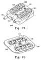
- FIG. 7Ais a perspective view of a clamp housing holding two interposers, one of which has an electrode lead inserted into it.
- FIG. 7Bis a perspective view of a variation of a connector carriage with spring contacts.
- FIG. 8is a cross-sectional view of the lead connector with spring contacts taken along line A-A′ of FIG. 3 .
- FIG. 9Ais a perspective view of a clamp housing holding the top half of two split interposers, one holding an electrode lead.
- FIG. 9Bis a perspective view of a variation of a connector carriage with spring contacts and the bottom halves of two split interposers.
- FIG. 1illustrates an implantable lead connector assembly 100 that is connectable to an electrode lead 105 .
- the connector housing 102 of the lead connector assembly 100desirably includes three conceptual parts: a clamp housing 101 , a connector carriage 107 , and an interposer or removable seal 109 .
- the inventive deviceshould have the following: a.) a functional clamp that holds the implantable lead connector assembly 100 closed and preferably simultaneously holds the various electrode leads in place while isolating the various electrical contacts, b.) an interposer or seal that accepts the proximal end of the various electrode leads and cooperatively (upon clamping or closing the inventive connector assembly) seals the various electrical contacts and “makes” the circuit with the lead contacts in such a way that the information or stimulus passing through the connector is isolated into the circuitry as intended by the designer, and c.) a connector carriage supporting the interposer, often serving as a portion of the clamping function, and desirably serving as passageway for electrical signals into and out of the attached stimulator or signal processor.
- the electrode lead 105is variously received by, held in place by, and positioned by an interposer or removable seal 109 that accommodates and electrically isolates electrical conductive members 121 in the connector carriage 107 .
- interposerremovable seal
- interposer sealmay be used to describe the component designated “ 109 ” in FIG. 1 because of the multiple functions performed by that component.
- each of the electrical conductive members 121make electrical contact with a corresponding lead terminus or proximal contact 123 on electrode lead 105 . It is often the case in such service, that some amount of fluid (typically conductive) may be present within the confines of inventive connector assembly 102 after the device is closed and in service.
- the interposer 109is to seal one electrical conductive member 121 from all non-common electrically conductive or active members thus tending to eliminate the passage of erroneous information to the attached signal processor and to certify the passage of stimulation to appropriate sectors of the brain.
- the electrical conductive members 121pass through the connector carriage 107 and eventually project from the lead connector assembly 100 as feedthrough pins 113 (FIG. 4) where they may be linked to an implantable device such as a signal processor or stimulator mentioned elsewhere.
- the connector housing 102(clamp housing 101 and connector carriage 107 ) may be joined by the fastener 103 actuating the inventive connector assembly.
- engaging the fastener 103seals the electrode lead 105 in the interposer seal 109 and presses the electrical conductive members 121 against the proximal contacts or termini 123 on electrode lead 105 . This forms an electrical circuit between the electrical conductive members 121 and the electrode lead.
- the lead connector assembly 100may receive multiple, e.g., one or two, electrode leads for connection to an implantable device.
- the connector housing 102may be extended or adapted to accommodate three or more electrode leads.
- the external profile of the connector housing 102is shown to be rectangular, the outer profiles of the clamp housing 101 and the cooperating connector carriage 107 may be of any convenient shape.
- the lead connector assembly's 100 shapemay be adapted to fit a mounting device or a neural stimulator or signal processing device.
- the lead connector assembly 100desirably is small enough to be implanted within a patient's cranium, in a patient's cranial bone wall, or under the patient's scalp.
- the overall dimensions of lead connector assembly 100will typically depend upon a variety of factors, e.g., the number of leads that the connector assembly is to accommodate, the size of the electrode leads, the size of the cranium, etc.
- the lead connector assembly 100 shown in FIG. 1has a depth of approximately 6.5 mm, and a length of approximately 15.0 mm and breadth of approximately 13.0 mm. As indicated, these dimensions are not limiting; the ultimate size and shape can vary greatly without affecting the performance of the device.
- the connector housing 102is shown to be made up of at least a clamp housing 101 and a connector carriage 107 .
- these two componentsare depicted to be separable and such separability facilitates installation and replacement of electrode lead 105 ; however the clamp housing 101 and a connector carriage 107 may be integrated into a single element or perhaps joined by a hinge.
- the clamp housingcan be made of a biocompatible material such as polyetheretherketone (PEEK).
- PEEKpolyetheretherketone
- the interior of the clamp housing 101holds the interposer 109 in place and therefore desirably conforms in shape to that interposer 109 . This concept is discussed in greater detail below, particularly with respect to FIG. 4 .
- the interior shape of the clamp housing 101is not limited to one having a recessed region that fits the shape of the interposer 109 .
- the interior of the clamp housing 101may include one or more sealing gaskets to isolate the interior of the clamp housing 101 from external fluids after closure of the connector housing 102 by fastener 103 .
- the interposer 109provides any required sealing.
- the interposer 109isolates each of the electrical/physical contacts occurring between the electrode lead 105 and the electrical conductive members 121 variously from each other and from the connector carriage 107 .
- the various gaskets and the interposer 109are made of a biocompatible polymer, perhaps an inert elastomer such as a suitable silicone (for example, MED4950, a medical grade silicone offered by NuSil Technology of Carpinteria, Calif.).
- a coating such as PARYLENEpolyparaxyxylene may be applied to prevent fusion adhesion between the seal and other surfaces.
- Clamp housing 101attaches to connector carriage 107 .
- the interior of the connector carriage 107desirably supports and conforms to the interposer 109 .
- this relationshipis seen by the recessed region 117 into which the interposer 109 fits.
- the framework of the connector carriage 107may be of a suitable biocompatible material, e.g., titanium.
- the region of the connector carriage 107 directly adjacent to the seating for the interposer 109is the baseplate 111 .
- Pin members 113pass through this baseplate 111 and project from the exterior of the connector carriage 107 (see FIG. 5) where they are connectable (directly or indirectly) to an implantable device such as a signal processor, stimulator, or other device.
- This variation of the inventionincludes non-integral pins 113 passing through baseplate 111 .
- the depicted pins 113are fixed to the baseplate 111 but, unlike the variation discussed above, are separable from the electrical conductive members 121 .
- Other variationsinclude, of course, the use of electrical conductive connectors 121 that are integrated with pins 113 .
- the baseplate 111supports or contains the electrical conductive members 121 and generally provides a sealing surface for interposer seal 109 .
- a filtering capacitor 405(FIG. 4) may be physically and electrically connected to baseplate 111 and to the electrical conductive members 121 .
- the electrical conductive members 121may also be secured to the baseplate 111 in a number of ways: for instance, by forming the baseplate 111 as a co-fired ceramic with appropriate choice of conductive regions, the electrical conductive members 121 may be made to be integral with the baseplate 111 .
- the electrical conductive members 121may be of an assemblage containing pins 113 that are attached to baseplate 111 by, e.g., use of a biocompatible brazing material.
- the connection to the electrode lead 105may include two parts: a feedthrough pin 113 and a compressible electrical connection member 121 .
- the compressible electrical connection members 121may be, for instance, spring contacts or fuzz button connectors and other similarly functional components.
- the compressible electrical connection members 121is a spring contact.
- a spring contactis an open or closed loop of a biocompatible, conductive material, such as a pure metal or an alloy (such as 80-20 Platinum-Iridium) that achieves a predictable amount of opposing force when compressed.
- the compressible electrical connection members 121may be fuzz buttons.
- Fuzz buttonsmay be made from a very fine diameter wire, e.g., of Pt—Ir, that is formed, much like a steel wool pad, into a shape approximating a cylinder. These forms are commercially available from Tecknit Co of Cranford, N.J. Others shapes (for example, multiple coils) and other conductive materials may also serve as compressible electrical connection members.
- the feedthrough pin 113is the portion of the electrical conductive member that extends through the baseplate 111 , projects externally, and may then be attached, directly or indirectly, to the implantable device.
- the feedthrough pin 113contains or is made of a suitable biocompatible, corrosion-resistant, highly conductive metal or alloy, e.g., a member of the Noble Metal group, e.g., platinum, palladium, iridium, and preferably alloys of platinum and iridium.
- the feedthrough pin 113 and the compressible electrical connection member 121may, of course, be fabricated from the same conductive material or even made as a single element.
- FIGS. 1-4The connector carriage utilizing fuzz button connectors is shown in FIGS. 1-4.
- the feedthrough pins 113 and fuzz button contacts 121are separable components of each electrical conductive member.
- FIGS. 6-9show highly preferred connector carriages comprising feedthrough pins and spring contact that are welded together (by laser welding, for example).
- the lead connector assembly 100 of FIG. 1is depicted to accept two interposer seals 109 each accommodating four electrical connections to each electrode lead 105 .
- the number of connections 123 from a particular electrode lead 105is not limited to four, but is set by the chosen geometry of the electrode lead 105 .
- the lead connector assembly 100 of this inventionmay be configured to connect to electrode leads having a much higher density of electrodes simply by designing the location or spacing of the electrical conductive members and interposer openings to conform with the number and spacing of the various electrode termini 123 .
- the connector housing 102is typically assembled by aligning the clamp housing 101 and the connector carriage 107 .
- Ancillary assembly designaids such as alignment posts 115 on the connector carriage 107 and matching holes (not shown) in the underside of the clamp housing 101 help in aligning the connector carriage 107 to the clamp housing 101 .
- Such alignment postsmay be installed into mating holes or sockets in the connector carriage (or the connector housing) or may be formed integrally with the carriage or housing.
- the clamp housing 101 and connector carriage 107may be secured together by the fastener 103 once the one or more electrode leads 105 are properly positioned in interposer 109 .
- the fastener 103 shown in FIG. 1is a screw-type locking mechanism, which would desirably be pre-installed and captured in the clamp housing 101 and is adapted to lock into a threaded hole found in the connector carriage 107 , sealing the electrode lead 105 in place within the interposer 109 .
- the fastener 103may be made out of a biocompatible polymer or of a metal such as titanium.
- the head of the exemplified fastener 103 shown FIG. 1is flush with the clamp housing 101 and has a hexagonal opening for fastening and unfastening. The ability to reopen and adjust this lead connector assembly 101 is an additional benefit of this invention.
- Fastener 103need not be a screw-type locking mechanism.
- the inventive lead connector assembly 100may be assembled around the electrode leads 105 .
- the proximal end (or “connector end”) of the depicted electrode lead 105has a number of proximal electrode contacts or termini 123 that are shown in FIG. 1 to be ring-type. Each of those proximal contacts 123 are in electrical contact with the distal lead electrodes implanted into the brain.
- the connector end of the electrode lead 105fits into the interposer 109 .
- the interposer 109may be made from any suitable biocompatible insulating material, such as a silicone (for example, MED4950 silicone from NuSil Technology), that is preferably elastomeric.
- the interposer 109includes an axial passageway to allow lengthwise entrance of the electrode lead 105 and openings extending generally radially to the axial passageway that typically contain the electrical connection members 121 discussed at length above. The physical and electrical contact between each proximal electrode contact 123 of the electrode lead 105 are thus made.
- FIG. 2Billustrates the underside of the interposer 109 shown in FIG. 2 A. This side contacts the baseplate of the connector carriage 107 as shown in FIG. 1 .
- the compressible electrical conductive members 205extend through the interposer 109 and are adapted to make electrical contact with the feedthrough pins 113 , shown in FIG. 1 .
- the compressible electrical conductive members 205may be held in the openings of the interposer 109 by various structures and adhesives.
- FIG. 4shows a cross-section through the sealed lead connector assembly 100 of FIG. 3 (at section line A′-A).
- the electrode leadis shown sectioned though an electrode contact 407 .
- the feedthrough pin 113is shown to be slightly concave to maximize the common contact surface area between the electrical conductor member 205 and the feedthrough pin 113 .
- This variation of the inventionshows the feedthrough pin 113 to be embedded in the baseplate 111 .
- the baseplate 111is seated into and is hermetically attached to the base of the connector carriage 107 and mates with the interposer 109 .
- the baseplate 111has a ceramic layer 403 that supports and insulates the feedthrough pins 113 and a capacitive element 405 that filters transients that are transmitted through the feedthrough pins 113 .
- the baseplate 111is held in the connector carriage 107 and may be supported by an annular lip 413 in the bottom of the depression into which the interposer 109 resides.
- the interposer 109is held in a recessed region of the connector carriage 107 , and the component rigid clips 203 hold the electrode contact in position against the electrical conductor member 205 .
- a complementary ramp 401is situated inside a complementary upper interposer seal 110 , in turn within clamp housing 101 .
- the complementary ramp 401maintains the “arms” of the molded clip 203 together and against the electrode lead.
- the complementary upper interposer seal 110secures the lead in place and promotes compressional contact between the electrical conductor member 205 and that electrode lead.
- Adjacent ramps 401may be seen seal component 108 portion of the complementary upper interposer seal 110 , mentioned above. This seal component 108 , in conjunction with the seal surfaces 206 (in FIG.
- the surfaces variously of the seal and the interposer 109may be provided with a coating 411 (for example, with PARYLENE) to prevent sticking or fusion adhesion amongst the seal 108 , the seal surface 206 (FIG. 2 A), the interposer 109 , and the electrode lead.
- the sealed lead connector assembly 100 of FIGS. 3 and 4are depicted to contain only one interposer and electrode lead. The space for a second lead 301 is shown unoccupied.
- FIG. 5shows the exterior lower surface of the connector carriage 107 .
- the exterior layer of the capacitor element 405is shown.
- the most distant or second end of the feedthrough pins 113project externally above the outer layer of the capacitor element 405 and is adapted to contact or otherwise to connect with an implantable device, such as a stimulator or signal processor.
- the cylindrical protrusion 417 in this variation of the inventionforms a complementary section of the fastener ( 103 in FIG. 1) in that it houses a female threaded section when the fastener 103 is a screw or bolt. Other fastener pairs will mandate other complementary fastener components in protrusion 417 . In this variation, the fastener screw threads into the connector carriage 107 .
- a locking nut or other locking mechanism, split ring, crown washersmay be employed to hold the fastener in place as eventually fastened, all as the designer sees fit.
- the shape of the protrusion 417 and of the entire outer surface of the connector carriage 107may be designed to allow mating to or attachment of an implantable device. Of course, numerous attachment methods are suitable for the fastener, provided that the hermeticity of any attached implantable device is not compromised.
- FIG. 6Ashows a second, but preferred, variation of the interposer 601 that works well when the electrical connection member 603 is a spring contact.
- the connector end or terminal end of a electrode leadis inserted axially into the hollow channel 605 .
- the various openings in the interposer 601allow the spring contacts to enter the interposer 601 and form an electrical connection with the proximal contacts of the electrode lead. It is desirable that the interposer 601 be sized in such a way that when later inserted into the clamp housing (see, for instance, the depiction in FIG.
- the clamp housingsqueezes the (preferably elastomeric) interposer 601 and, in turn, squeezes the lead and retains both in a properly aligned condition for subsequent assembly into the completed inventive housing assembly.
- a “properly aligned condition”means that the proximal contacts of the electrode lead are aligned in position for later electrical continuity with the complementary portions of the inventive device, e.g., the electrode lead has not undertaken any axial or longitudinal movement with respect to the to interposer.
- the use of the interposer to temporarily maintain various portions of the inventive device in practical subassemblies during a surgical procedureis applicable to other variations of the interposer discussed elsewhere in this specification. Indeed, it is within the scope of this invention to use other devices or assembly aids to hold various parts of the inventive device together during those surgical procedures.
- FIG. 6Bshows a perspective view of a variation of the interposer 620 that is substantially closed, having only one opening, an axial passageway 622 , that is adapted to accept the proximal end of an electrode lead.
- the compressible electric conductor membersare conductive regions 624 that match up with the spacings of the proximal contacts on an electrode lead.
- the interposer 620is desirably of a selection of polymers, preferably elastomers, adapted to create the differential conductivity.
- the conductive regions 624are surrounded by nonconductive areas or regions 626 that allow isolation of the current flow from or to the electrode lead to the passthrough terminals discussed elsewhere. Construction of this variation via normal polymer molding techniques should be apparent to those of ordinary skill in this art.
- the spring clip and fuzz buttons discussed elsewhereare not necessary in this variation.
- the axial passageway or bore 622is shown to be smooth, other bore configurations are suitable, e.g., with projections, projecting rings, etc.
- the functions of contact and of sealingare to be accomplished by the structure, however. This variation fits into the connector carriage 107 in the same way as do the other variations discussed elsewhere.
- FIG. 6Cshows a cross-section of the FIG. 6B interposer 620 . Shown are the conductive regions 624 and the surrounding non-conductive areas or regions 626 as well as the axial bore or passageway 622 .
- the interposer 620 deviceis depicted to be symmetrical, although it need not be.
- the conductive regions 624may be situated on but one side of the interposer 620 adjacent the passthrough terminals, although the installation in the housing must be made with more care.
- FIG. 6Dshows a perspective view of another variation of the interposer 640 that comprises compressible electric conductor members that are conductive regions 642 surrounded by a non-conductive region or regions 644 .
- This variationrequires a separate cooperating upper shell to complete the seal portions shown in the axial passageway 648 .
- the axial passageway 648is adapted to accept the proximal end of an electrode lead.
- the compressible electric conductor membersare conductive regions 642 that match up in physical spacing with the spacings of the proximal contacts on an electrode lead. This variation fits into the connector carriage 107 in the same way as do the other variations discussed elsewhere.
- FIG. 6Eshows a cross-section of the FIG. 6D interposer 640 . Shown are the conductive regions 642 and the surrounding non-conductive area or regions 644 as well as the axial bore or passageway 648 .
- FIGS. 7A and 7Bshow placement of the interposer 601 , after insertion of the electrode lead 105 into that interposer, in turn into the connector carriage 107 much in the same way as shown in FIGS. 1 and 4 above.
- the interposer 601is held in the clamp housing 101 .
- the clamp housing 101 and the interposer 601may be integrated into a single structure.
- the interposermay be preattached to the clamp housing 101 .
- An electrode lead 105is inserted into one of the interposers 601 .
- the connector carriage 107may be aligned with the clamp housing 101 using optional alignment posts 115 fitting into complementary holes 701 on the clamp housing 101 .
- the electrical connection members (the spring contacts) 703are welded to the proximal side of the feedthrough pins on the connector carriage (e.g., by laser spot welding).
- the spring contactcan be made of a suitably springy, conductive, preferably inert metal or alloy (such as 80-20 Platinum-Iridium).
- FIG. 8is another cross-section of the lead connector assembly 100 , this time showing the electrical connection members (the spring contacts) 703 and the interposer 601 of FIGS. 6, 7 A, and 7 B.
- the electrical connection members (the spring contacts) 703have been attached to the feedthrough pin 113 , perhaps by welding, and is in electrical contact with a proximal electrode or terminus of electrode lead 407 .
- the clamp housing 101is locked onto the connector carriage 107 using fastener 103 .
- This whole variation of the interposeralso effectively seals the electrical contact between the electrode lead and the compressible electrical connection member from external fluids and from adjacent non-common electrical contacts and from any conductive portions of connector carriage 107 .
- the lower half 905 of the interposeris attached to the lead positioners 910 and has openings that fit the spring contacts 703 attached to the feedthrough pins (not seen in this view).
- the interposer upper half 901 and lower half 905may each be produced in such a way as to be affixed permanently in the respective clamp housing 101 and connector carriage 107 or they may be made in such a way as to be removable.
- the alignment posts 115help join the clamp housing 101 to the connector carriage, connecting the lower half 905 of the interposer with the upper half 901 of the interposer.
- the alignment posts 115 in FIGS. 9A and 9B(just as in FIG. 1) project from the connector carriage into the clamp housing 101 .
- the alignment postsmay just as well project from the clamp housing 101 into the connector carriage 107 .
- alignment pinsmay be completely separate elements.
- One other desirable featureis the presence of one or more lead positioners 910 such as are shown in FIG. 9 A.
- the lead positioners 910are situated in the clamp housing 101 .
- This hooped variation of the lead positioner 910allows a user physician to situate the lead 105 into the clamp housing 101 and be sure that that lead 105 is properly positioned so that as the clamp housing 101 is later placed onto the connector carriage 107 , the proximal contacts 123 on that lead 105 are properly indexed onto the spring contacts 703 . Additionally, this arrangement allows sequential assembly of the inventive device in the operating room and makes fewer the number of parts the physician must coordinate at any one time during that assembly.
- an implantable lead connector made or used according to the inventionmay differ from the disclosed variations in numerous ways.
- variations of the present inventionmay be employed in many different applications for sensing or stimulation, not just in the brain.
- Lead connectors according to the inventionmay have utility in connecting devices to lead in peripheral nerves, other portions of the body, and other applications. Rather, the invention is to cover all modifications, equivalents, and alternatives falling within the spirit of the invention as defined by the appended claims.
Landscapes
- Health & Medical Sciences (AREA)
- Neurology (AREA)
- Neurosurgery (AREA)
- Psychology (AREA)
- Cardiology (AREA)
- Heart & Thoracic Surgery (AREA)
- Engineering & Computer Science (AREA)
- Biomedical Technology (AREA)
- Nuclear Medicine, Radiotherapy & Molecular Imaging (AREA)
- Radiology & Medical Imaging (AREA)
- Life Sciences & Earth Sciences (AREA)
- Animal Behavior & Ethology (AREA)
- General Health & Medical Sciences (AREA)
- Public Health (AREA)
- Veterinary Medicine (AREA)
- Electrotherapy Devices (AREA)
Abstract
Description
Claims (39)
Priority Applications (1)
| Application Number | Priority Date | Filing Date | Title |
|---|---|---|---|
| US09/951,234US6662035B2 (en) | 2001-09-13 | 2001-09-13 | Implantable lead connector assembly for implantable devices and methods of using it |
Applications Claiming Priority (1)
| Application Number | Priority Date | Filing Date | Title |
|---|---|---|---|
| US09/951,234US6662035B2 (en) | 2001-09-13 | 2001-09-13 | Implantable lead connector assembly for implantable devices and methods of using it |
Publications (2)
| Publication Number | Publication Date |
|---|---|
| US20030050549A1 US20030050549A1 (en) | 2003-03-13 |
| US6662035B2true US6662035B2 (en) | 2003-12-09 |
Family
ID=25491462
Family Applications (1)
| Application Number | Title | Priority Date | Filing Date |
|---|---|---|---|
| US09/951,234Expired - LifetimeUS6662035B2 (en) | 2001-09-13 | 2001-09-13 | Implantable lead connector assembly for implantable devices and methods of using it |
Country Status (1)
| Country | Link |
|---|---|
| US (1) | US6662035B2 (en) |
Cited By (133)
| Publication number | Priority date | Publication date | Assignee | Title |
|---|---|---|---|---|
| US20020049451A1 (en)* | 2000-08-17 | 2002-04-25 | Kari Parmer | Trajectory guide with instrument immobilizer |
| US20020052610A1 (en)* | 2000-04-07 | 2002-05-02 | Skakoon James G. | Deep organ access device and method |
| US20030199948A1 (en)* | 2002-04-19 | 2003-10-23 | Kokones Scott B. | Multiport neurological screening cable |
| US20040015204A1 (en)* | 2002-06-20 | 2004-01-22 | Whitehurst Todd K. | Implantable microstimulators and methods for unidirectional propagation of action potentials |
| US20040054393A1 (en)* | 2000-01-21 | 2004-03-18 | Goran Stemme | Medical electrode |
| US6782288B2 (en) | 1998-10-08 | 2004-08-24 | Regents Of The University Of Minnesota | Method and apparatus for positioning a device in a body |
| US20050060003A1 (en)* | 2003-09-12 | 2005-03-17 | Taylor William J. | Feedthrough apparatus with noble metal-coated leads |
| US20050085884A1 (en)* | 2003-10-20 | 2005-04-21 | O'brien Robert C. | Connection for a coiled lead to an electrical contact for an implantable medical device |
| US20050228249A1 (en)* | 2004-04-09 | 2005-10-13 | Neuropace, Inc. | Implantable lead system with seed electrodes |
| US20060047322A1 (en)* | 2004-08-26 | 2006-03-02 | Jacques Naviaux | Electrical conductive path for a medical electronics device |
| US20060148326A1 (en)* | 2005-01-04 | 2006-07-06 | Putz David A | Multiple-use, stimulation-accommodating connector |
| US20060161215A1 (en)* | 2005-01-18 | 2006-07-20 | Jacques Naviaux | Weld plate contact for implanted medical devices |
| US7117033B2 (en) | 2000-05-08 | 2006-10-03 | Brainsgate, Ltd. | Stimulation for acute conditions |
| US7120489B2 (en) | 2000-05-08 | 2006-10-10 | Brainsgate, Ltd. | Method and apparatus for stimulating the sphenopalatine ganglion to modify properties of the BBB and cerebral blood flow |
| US20060247714A1 (en)* | 2005-04-28 | 2006-11-02 | Taylor William J | Glass-to-metal feedthrough seals having improved durability particularly under AC or DC bias |
| US7146209B2 (en) | 2000-05-08 | 2006-12-05 | Brainsgate, Ltd. | Stimulation for treating eye pathologies |
| US7209787B2 (en) | 1998-08-05 | 2007-04-24 | Bioneuronics Corporation | Apparatus and method for closed-loop intracranial stimulation for optimal control of neurological disease |
| US20070112404A1 (en)* | 2005-11-16 | 2007-05-17 | Mann Alfred E | Implantable stimulator |
| US7231254B2 (en) | 1998-08-05 | 2007-06-12 | Bioneuronics Corporation | Closed-loop feedback-driven neuromodulation |
| US20070142888A1 (en)* | 2005-12-20 | 2007-06-21 | Alfonso Chavez | Implantable leads and methods of using the same |
| US7242984B2 (en) | 1998-08-05 | 2007-07-10 | Neurovista Corporation | Apparatus and method for closed-loop intracranial stimulation for optimal control of neurological disease |
| US20070213783A1 (en)* | 2006-03-13 | 2007-09-13 | Neuropace, Inc. | Implantable system enabling responsive therapy for pain |
| US20070219595A1 (en)* | 2006-03-14 | 2007-09-20 | Advanced Bionics Corporation | Stimulator system with electrode array and the method of making the same |
| WO2007109762A1 (en)* | 2006-03-23 | 2007-09-27 | Medtronic, Inc. | Medical electrical lead connection systems and methods |
| US7277758B2 (en) | 1998-08-05 | 2007-10-02 | Neurovista Corporation | Methods and systems for predicting future symptomatology in a patient suffering from a neurological or psychiatric disorder |
| US20070260282A1 (en)* | 2003-09-12 | 2007-11-08 | Taylor William J | Feedthrough apparatus with noble metal-coated leads |
| US7324851B1 (en) | 1998-08-05 | 2008-01-29 | Neurovista Corporation | Closed-loop feedback-driven neuromodulation |
| US7403820B2 (en) | 1998-08-05 | 2008-07-22 | Neurovista Corporation | Closed-loop feedback-driven neuromodulation |
| USD577672S1 (en)* | 2007-03-19 | 2008-09-30 | Yi Hui Yao | Lead connector |
| WO2008119041A1 (en)* | 2007-03-27 | 2008-10-02 | Cranial Medical Systems, Inc. | Anchoring apparatus and methods for use |
| US20080312716A1 (en)* | 2005-06-16 | 2008-12-18 | Russell Michael J | Methods and Systems for Using Intracranial Electrodes |
| US20090043220A1 (en)* | 2004-12-22 | 2009-02-12 | Montgomery Jr Erwin B | Methods and devices for analysis of clustered data, in particular action potentials (i.e. neuron firing signals in the brain) |
| US7497863B2 (en) | 2004-12-04 | 2009-03-03 | Medtronic, Inc. | Instrument guiding stage apparatus and method for using same |
| US7561919B2 (en) | 2002-11-14 | 2009-07-14 | Brainsgate Ltd. | SPG stimulation via the greater palatine canal |
| US7559935B2 (en) | 2003-02-20 | 2009-07-14 | Medtronic, Inc. | Target depth locators for trajectory guide for introducing an instrument |
| US20090233491A1 (en)* | 2008-03-12 | 2009-09-17 | Boston Scientific Neuromodulation Corporation | Low-profile connector for a neurostimulation lead |
| US20090248124A1 (en)* | 2008-03-27 | 2009-10-01 | Boston Scientific Neuromodulation Corporation | Lead identifier for an implantable electric stimulation system and methods of making and using |
| US20090264943A1 (en)* | 2008-04-21 | 2009-10-22 | Boston Scientific Neuromodulation Corporation | High-resolution connector for a neurostimulation lead |
| US20090287287A1 (en)* | 2006-07-31 | 2009-11-19 | Cranial Medical Systems, Inc. | Multi-channel connector for brain stimulation system |
| US7627383B2 (en) | 2005-03-15 | 2009-12-01 | Boston Scientific Neuromodulation Corporation | Implantable stimulator |
| US7636596B2 (en) | 2002-12-20 | 2009-12-22 | Medtronic, Inc. | Organ access device and method |
| US7636597B2 (en) | 2002-11-14 | 2009-12-22 | Brainsgate, Ltd. | Surgical tools and techniques for stimulation |
| US7640062B2 (en) | 2000-05-08 | 2009-12-29 | Brainsgate Ltd. | Methods and systems for management of alzheimer's disease |
| US7658879B2 (en) | 2003-02-20 | 2010-02-09 | Medtronic, Inc. | Trajectory guide with angled or patterned guide lumens or height adjustment |
| US20100070007A1 (en)* | 2008-09-17 | 2010-03-18 | National Ict Australia Limited | Knitted electrode assembly and integrated connector for an active implantable medical device |
| US20100070012A1 (en)* | 2008-09-15 | 2010-03-18 | Boston Scientific Neuromodulation Corporation | Lead connection system for an implantable electrical stimulation system and methods for making and using the systems |
| US7684859B2 (en) | 2002-04-25 | 2010-03-23 | Brainsgate Ltd. | Stimulation of the OTIC ganglion for treating medical conditions |
| US7704260B2 (en) | 2002-09-17 | 2010-04-27 | Medtronic, Inc. | Low profile instrument immobilizer |
| US7729758B2 (en) | 2005-11-30 | 2010-06-01 | Boston Scientific Neuromodulation Corporation | Magnetically coupled microstimulators |
| US7736191B1 (en)* | 2008-05-27 | 2010-06-15 | Jerzy Roman Sochor | Implantable connector with protected contacts |
| US7747325B2 (en) | 1998-08-05 | 2010-06-29 | Neurovista Corporation | Systems and methods for monitoring a patient's neurological disease state |
| US7744606B2 (en) | 2004-12-04 | 2010-06-29 | Medtronic, Inc. | Multi-lumen instrument guide |
| US7794256B1 (en)* | 2007-08-09 | 2010-09-14 | Jerzy Roman Sochor | Implantable connector with contact-containing feedthrough pins |
| US20100240253A1 (en)* | 2007-10-03 | 2010-09-23 | Medltronic Inc. | Connector Assemblies for Implantable Medical Electrical Systems |
| US20100240240A1 (en)* | 2009-03-19 | 2010-09-23 | Ochoa Francisco | Flexible connector for implantable electrical stimulation lead |
| US20100304592A1 (en)* | 2007-10-02 | 2010-12-02 | Kast John E | Connector Assemblies and Contacts for Implantable Medical Electrical Systems |
| US7860569B2 (en) | 2007-10-18 | 2010-12-28 | Brainsgate, Ltd. | Long-term SPG stimulation therapy for prevention of vascular dementia |
| US20110000699A1 (en)* | 2009-06-04 | 2011-01-06 | David Joseph Bealka | Co-fired metal and ceramic composite feedthrough assemblies for use at least in implantable medical devices and methods for making the same |
| US7877136B1 (en) | 2007-09-28 | 2011-01-25 | Boston Scientific Neuromodulation Corporation | Enhancement of neural signal transmission through damaged neural tissue via hyperpolarizing electrical stimulation current |
| US20110022100A1 (en)* | 2009-07-21 | 2011-01-27 | Boston Scientific Neuromodulation Corporation | Multi-port modular connector for implantable electrical stimulation systems and methods of making and using |
| US7908000B2 (en) | 2004-02-20 | 2011-03-15 | Brainsgate Ltd. | Transmucosal electrical stimulation |
| US7957793B2 (en) | 2004-12-22 | 2011-06-07 | Wisconsin Alumni Research Foundation | Methods for identifying neuronal spikes |
| US20110270187A1 (en)* | 2010-04-28 | 2011-11-03 | Nelson Brian D | Body portal anchors and systems |
| US8055347B2 (en) | 2005-08-19 | 2011-11-08 | Brainsgate Ltd. | Stimulation for treating brain events and other conditions |
| US20120053646A1 (en)* | 2010-08-31 | 2012-03-01 | Boston Scientific Neuromodulation Corporation | Systems and methods for making and using connector assembly retainers for electrical stimulation systems |
| US8162684B1 (en)* | 2008-08-07 | 2012-04-24 | Jerzy Roman Sochor | Implantable connector with contact-containing feedthrough pins |
| US20120110844A1 (en)* | 2006-09-22 | 2012-05-10 | Johnson Corinne H | Methods and systems for securing electrode leads |
| EP2497419A1 (en) | 2011-03-10 | 2012-09-12 | BIOTRONIK SE & Co. KG | Multi-electrode leads for brain implantation |
| US8267708B1 (en)* | 2007-08-09 | 2012-09-18 | Jerzy Roman Sochor | Implantable feedthrough-based connector |
| WO2012140629A1 (en) | 2011-04-15 | 2012-10-18 | Universidade Do Porto | Polymer-based electrode for bio-signal recording |
| EP2153493A4 (en)* | 2007-03-30 | 2013-01-23 | Ball It Oy | Airtight electrical socket |
| US8369951B2 (en)* | 2011-03-29 | 2013-02-05 | Greatbatch Ltd. | Feed-through connector assembly for implantable pulse generator and method of use |
| US20130184804A1 (en)* | 2007-01-22 | 2013-07-18 | Cochlear Limited | Implantable component interface |
| US8500499B2 (en) | 2009-08-05 | 2013-08-06 | Medtronic, Inc. | Contact assemblies for medical devices having resilient contact members mounted in channels of a mounting member |
| US8725243B2 (en) | 2005-12-28 | 2014-05-13 | Cyberonics, Inc. | Methods and systems for recommending an appropriate pharmacological treatment to a patient for managing epilepsy and other neurological disorders |
| US8738141B2 (en) | 2011-04-07 | 2014-05-27 | Greatbatch, Ltd. | Contact assembly for implantable pulse generator and method of use |
| US8762065B2 (en) | 1998-08-05 | 2014-06-24 | Cyberonics, Inc. | Closed-loop feedback-driven neuromodulation |
| US8868172B2 (en) | 2005-12-28 | 2014-10-21 | Cyberonics, Inc. | Methods and systems for recommending an appropriate action to a patient for managing epilepsy and other neurological disorders |
| US9042988B2 (en) | 1998-08-05 | 2015-05-26 | Cyberonics, Inc. | Closed-loop vagus nerve stimulation |
| US9138586B2 (en) | 2012-01-27 | 2015-09-22 | Greatbatch Ltd. | Contact block using spherical electrical contacts for electrically contacting implantable leads |
| US9203175B1 (en) | 2013-01-24 | 2015-12-01 | Pmt Corporation | Inline connector assembly |
| US9233245B2 (en) | 2004-02-20 | 2016-01-12 | Brainsgate Ltd. | SPG stimulation |
| US9307925B2 (en) | 2005-06-16 | 2016-04-12 | Aaken Laboratories | Methods and systems for generating electrical property maps of biological structures |
| US9375573B2 (en) | 1998-08-05 | 2016-06-28 | Cyberonics, Inc. | Systems and methods for monitoring a patient's neurological disease state |
| US9403022B2 (en) | 2010-01-29 | 2016-08-02 | Medtronic, Inc. | Header assembly for implantable medical device |
| US9409028B2 (en) | 2002-06-20 | 2016-08-09 | Boston Scientific Neuromodulation Corporation | Implantable microstimulators with programmable multielectrode configuration and uses thereof |
| US9517338B1 (en)* | 2016-01-19 | 2016-12-13 | Axonics Modulation Technologies, Inc. | Multichannel clip device and methods of use |
| US9675796B2 (en) | 2013-11-10 | 2017-06-13 | Brainsgate Ltd. | Implant and delivery system for neural stimulator |
| US20170203098A1 (en)* | 2016-01-19 | 2017-07-20 | Axonics Modulation Technologies, Inc. | Multichannel clip device and methods of use |
| US9931513B2 (en) | 2011-03-29 | 2018-04-03 | Nuvectra Corporation | Feed-through connector assembly for implantable pulse generator and method of use |
| US9956394B2 (en) | 2015-09-10 | 2018-05-01 | Boston Scientific Neuromodulation Corporation | Connectors for electrical stimulation systems and methods of making and using |
| US9972951B1 (en)* | 2017-06-30 | 2018-05-15 | Benchmark Electronics, Inc. | Medical lead connectors with contact electrodes |
| US10086193B2 (en) | 2004-02-13 | 2018-10-02 | Medtronic, Inc. | Apparatus for securing a therapy delivery device within a burr hole and method for making same |
| US10201713B2 (en) | 2016-06-20 | 2019-02-12 | Boston Scientific Neuromodulation Corporation | Threaded connector assembly and methods of making and using the same |
| US10271907B2 (en) | 2015-05-13 | 2019-04-30 | Brainsgate Ltd. | Implant and delivery system for neural stimulator |
| EP3487005A1 (en)* | 2017-11-21 | 2019-05-22 | BIOTRONIK SE & Co. KG | Clip for making a mechanical and electrically conductive connection between the clip and a pin, especially a feedthrough pin |
| US10307602B2 (en) | 2016-07-08 | 2019-06-04 | Boston Scientific Neuromodulation Corporation | Threaded connector assembly and methods of making and using the same |
| US10342983B2 (en) | 2016-01-14 | 2019-07-09 | Boston Scientific Neuromodulation Corporation | Systems and methods for making and using connector contact arrays for electrical stimulation systems |
| WO2019192370A1 (en)* | 2018-04-03 | 2019-10-10 | 阿木(深圳)新科技有限公司 | Signal processor mounting device for clothes |
| US10471251B1 (en) | 2018-07-31 | 2019-11-12 | Manicka Institute Llc | Subcutaneous device for monitoring and/or providing therapies |
| WO2019218777A1 (en)* | 2018-05-15 | 2019-11-21 | 阿木(深圳)新科技有限公司 | Lead device and electrocardiogram clothing |
| US10543374B2 (en) | 2016-09-30 | 2020-01-28 | Boston Scientific Neuromodulation Corporation | Connector assemblies with bending limiters for electrical stimulation systems and methods of making and using same |
| WO2020027888A1 (en)* | 2018-07-31 | 2020-02-06 | Manicka Institute Llc | Subcutaneous device |
| US10569093B1 (en) | 2018-07-31 | 2020-02-25 | Manicka Institute Llc | Injectable subcutaneous device |
| US10608390B2 (en) | 2017-06-30 | 2020-03-31 | Benchmark Electronics, Inc. | Medical lead connectors with contact electrodes |
| US10603499B2 (en) | 2017-04-07 | 2020-03-31 | Boston Scientific Neuromodulation Corporation | Tapered implantable lead and connector interface and methods of making and using |
| US10639485B2 (en) | 2017-09-15 | 2020-05-05 | Boston Scientific Neuromodulation Corporation | Actuatable lead connector for an operating room cable assembly and methods of making and using |
| US10644468B2 (en) | 2017-06-30 | 2020-05-05 | Benchmark Electronics, Inc. | Medical lead connectors with contact electrodes |
| US10716511B2 (en) | 2018-07-31 | 2020-07-21 | Manicka Institute Llc | Subcutaneous device for monitoring and/or providing therapies |
| US10779882B2 (en) | 2009-10-28 | 2020-09-22 | Ethicon Endo-Surgery, Inc. | Electrical ablation devices |
| US10814136B2 (en) | 2017-02-28 | 2020-10-27 | Boston Scientific Neuromodulation Corporation | Toolless connector for latching stimulation leads and methods of making and using |
| US10892573B1 (en)* | 2019-01-04 | 2021-01-12 | Verily Life Sciences Llc | Thin-film connectors for data acquisition system |
| US10905871B2 (en) | 2017-01-27 | 2021-02-02 | Boston Scientific Neuromodulation Corporation | Lead assemblies with arrangements to confirm alignment between terminals and contacts |
| US10918873B2 (en) | 2017-07-25 | 2021-02-16 | Boston Scientific Neuromodulation Corporation | Systems and methods for making and using an enhanced connector of an electrical stimulation system |
| US10987060B1 (en) | 2020-09-14 | 2021-04-27 | Calyan Technologies, Inc. | Clip design for a subcutaneous device |
| US11045656B2 (en) | 2017-09-15 | 2021-06-29 | Boston Scientific Neuromodulation Corporation | Biased lead connector for operating room cable assembly and methods of making and using |
| US11052259B2 (en)* | 2018-05-11 | 2021-07-06 | Boston Scientific Neuromodulation Corporation | Connector assembly for an electrical stimulation system and methods of making and using |
| US11103712B2 (en) | 2018-01-16 | 2021-08-31 | Boston Scientific Neuromodulation Corporation | Connector assemblies with novel spacers for electrical stimulation systems and methods of making and using same |
| US11139603B2 (en) | 2017-10-03 | 2021-10-05 | Boston Scientific Neuromodulation Corporation | Connectors with spring contacts for electrical stimulation systems and methods of making and using same |
| US11179571B2 (en) | 2018-07-31 | 2021-11-23 | Manicka Institute Llc | Subcutaneous device for monitoring and/or providing therapies |
| US11284918B2 (en) | 2012-05-14 | 2022-03-29 | Cilag GmbH Inlernational | Apparatus for introducing a steerable camera assembly into a patient |
| US11357992B2 (en) | 2019-05-03 | 2022-06-14 | Boston Scientific Neuromodulation Corporation | Connector assembly for an electrical stimulation system and methods of making and using |
| US11395923B2 (en) | 2018-11-16 | 2022-07-26 | Verily Life Sciences Llc | Branched proximal connectors for high density neural interfaces |
| US11399834B2 (en) | 2008-07-14 | 2022-08-02 | Cilag Gmbh International | Tissue apposition clip application methods |
| US11406317B2 (en) | 2007-12-28 | 2022-08-09 | Livanova Usa, Inc. | Method for detecting neurological and clinical manifestations of a seizure |
| US11433233B2 (en) | 2020-11-25 | 2022-09-06 | Calyan Technologies, Inc. | Electrode contact for a subcutaneous device |
| US20220311173A1 (en)* | 2021-03-25 | 2022-09-29 | Neuropace, Inc. | Connector assembly for active implantable medical device |
| US11484191B2 (en) | 2013-02-27 | 2022-11-01 | Cilag Gmbh International | System for performing a minimally invasive surgical procedure |
| US11660444B2 (en) | 2018-07-31 | 2023-05-30 | Manicka Institute Llc | Resilient body component contact for a subcutaneous device |
| US11717674B2 (en) | 2018-07-31 | 2023-08-08 | Manicka Institute Llc | Subcutaneous device for use with remote device |
| US12070611B2 (en) | 2018-09-18 | 2024-08-27 | Verily Life Sciences Llc | Stimulation system with monolithic-lead component connected to skull mount package |
| US12106876B2 (en) | 2018-09-18 | 2024-10-01 | Verily Life Sciences Llc | Monolithic lead assembly and methods of microfabricating a monolithic lead assembly |
| US12343547B2 (en) | 2021-08-19 | 2025-07-01 | Boston Scientific Neuromodulation Corporation | Connectors for an electrical stimulation system and methods of making and using |
Families Citing this family (34)
| Publication number | Priority date | Publication date | Assignee | Title |
|---|---|---|---|---|
| US9320900B2 (en) | 1998-08-05 | 2016-04-26 | Cyberonics, Inc. | Methods and systems for determining subject-specific parameters for a neuromodulation therapy |
| US9415222B2 (en) | 1998-08-05 | 2016-08-16 | Cyberonics, Inc. | Monitoring an epilepsy disease state with a supervisory module |
| US8065008B2 (en) | 2003-08-21 | 2011-11-22 | Medtronic, Inc. | Multi-polar electrical medical lead connector system |
| US8019420B2 (en)* | 2003-08-21 | 2011-09-13 | Medtronic, Inc. | Medical lead connector systems with adapters |
| US7564674B2 (en)* | 2005-12-12 | 2009-07-21 | Greatbatch Ltd. | Feedthrough filter capacitor assemblies having low cost terminal pins |
| US20070149952A1 (en)* | 2005-12-28 | 2007-06-28 | Mike Bland | Systems and methods for characterizing a patient's propensity for a neurological event and for communicating with a pharmacological agent dispenser |
| US20070287931A1 (en)* | 2006-02-14 | 2007-12-13 | Dilorenzo Daniel J | Methods and systems for administering an appropriate pharmacological treatment to a patient for managing epilepsy and other neurological disorders |
| US20080021341A1 (en)* | 2006-06-23 | 2008-01-24 | Neurovista Corporation A Delware Corporation | Methods and Systems for Facilitating Clinical Trials |
| US8295934B2 (en)* | 2006-11-14 | 2012-10-23 | Neurovista Corporation | Systems and methods of reducing artifact in neurological stimulation systems |
| DE102006053729A1 (en)* | 2006-11-15 | 2008-05-21 | Biotronik Crm Patent Ag | Contact assembly, contact assembly, implantable device and electrode lead |
| EP2126785A2 (en) | 2007-01-25 | 2009-12-02 | NeuroVista Corporation | Systems and methods for identifying a contra-ictal condition in a subject |
| WO2008092133A2 (en) | 2007-01-25 | 2008-07-31 | Neurovista Corporation | Methods and systems for measuring a subject's susceptibility to a seizure |
| EP2126791A2 (en)* | 2007-02-21 | 2009-12-02 | NeuroVista Corporation | Methods and systems for characterizing and generating a patient-specific seizure advisory system |
| US8036736B2 (en) | 2007-03-21 | 2011-10-11 | Neuro Vista Corporation | Implantable systems and methods for identifying a contra-ictal condition in a subject |
| US7537474B2 (en)* | 2007-07-12 | 2009-05-26 | Medtronic, Inc. | Lead receptacle and pin frame assembly |
| US9788744B2 (en) | 2007-07-27 | 2017-10-17 | Cyberonics, Inc. | Systems for monitoring brain activity and patient advisory device |
| US9259591B2 (en) | 2007-12-28 | 2016-02-16 | Cyberonics, Inc. | Housing for an implantable medical device |
| EP2369986A4 (en)* | 2008-12-23 | 2013-08-28 | Neurovista Corp | Brain state analysis based on select seizure onset characteristics and clinical manifestations |
| US8849390B2 (en) | 2008-12-29 | 2014-09-30 | Cyberonics, Inc. | Processing for multi-channel signals |
| US8588933B2 (en) | 2009-01-09 | 2013-11-19 | Cyberonics, Inc. | Medical lead termination sleeve for implantable medical devices |
| US8786624B2 (en) | 2009-06-02 | 2014-07-22 | Cyberonics, Inc. | Processing for multi-channel signals |
| US9643019B2 (en) | 2010-02-12 | 2017-05-09 | Cyberonics, Inc. | Neurological monitoring and alerts |
| US20110219325A1 (en)* | 2010-03-02 | 2011-09-08 | Himes David M | Displaying and Manipulating Brain Function Data Including Enhanced Data Scrolling Functionality |
| US20110218820A1 (en)* | 2010-03-02 | 2011-09-08 | Himes David M | Displaying and Manipulating Brain Function Data Including Filtering of Annotations |
| EP2877239B1 (en)* | 2012-07-26 | 2023-06-21 | Nyxoah SA | Electrical contacts on a medical device patch |
| US9907967B2 (en) | 2012-07-26 | 2018-03-06 | Adi Mashiach | Transcutaneous power conveyance device |
| US9545290B2 (en)* | 2012-07-30 | 2017-01-17 | Ethicon Endo-Surgery, Inc. | Needle probe guide |
| US20140214143A1 (en)* | 2013-01-31 | 2014-07-31 | Ronnie Levy | Electrostimulation in treating cerebrovascular conditions |
| EP2994191A1 (en)* | 2013-05-10 | 2016-03-16 | Advanced Bionics AG | Thin profile cochlear implants |
| KR101656723B1 (en)* | 2015-06-30 | 2016-09-12 | 재단법인 오송첨단의료산업진흥재단 | Feedthrough making method |
| WO2018136595A1 (en)* | 2017-01-19 | 2018-07-26 | Evergreen Medical Technologies, Inc. | Implantable lead interconnect system |
| US10608354B2 (en)* | 2017-03-23 | 2020-03-31 | Verily Life Sciences Llc | Implantable connector with two electrical components |
| JP7235052B2 (en)* | 2018-09-27 | 2023-03-08 | 株式会社村田製作所 | In vivo implantable electronic device |
| CN112618949A (en) | 2019-10-08 | 2021-04-09 | 苏州景昱医疗器械有限公司 | Connector assembly for implantable medical device and method of making same |
Citations (33)
| Publication number | Priority date | Publication date | Assignee | Title |
|---|---|---|---|---|
| US4495917A (en)* | 1982-03-26 | 1985-01-29 | The Regents Of The University Of California | Surgically implantable disconnect device |
| US4516820A (en)* | 1983-01-27 | 1985-05-14 | The Commonwealth Of Australia | Cochlear prosthesis package connector |
| US4519659A (en) | 1982-12-07 | 1985-05-28 | Shin-Etsu Polymer Co., Ltd. | Socket-type connector for flat cables |
| US4712557A (en)* | 1986-04-28 | 1987-12-15 | Cordis Leads, Inc. | A pacer including a multiple connector assembly with removable wedge and method of use |
| US4735208A (en) | 1987-01-09 | 1988-04-05 | Ad-Tech Medical Instrument Corp. | Subdural strip electrode for determining epileptogenic foci |
| US4850359A (en) | 1987-10-16 | 1989-07-25 | Ad-Tech Medical Instrument Corporation | Electrical brain-contact devices |
| US4869255A (en) | 1987-12-04 | 1989-09-26 | Ad-Tech Medical Instrument Corp. | Electrical connection device |
| US4903702A (en) | 1988-10-17 | 1990-02-27 | Ad-Tech Medical Instrument Corporation | Brain-contact for sensing epileptogenic foci with improved accuracy |
| US5097835A (en) | 1990-04-09 | 1992-03-24 | Ad-Tech Medical Instrument Corporation | Subdural electrode with improved lead connection |
| US5215089A (en) | 1991-10-21 | 1993-06-01 | Cyberonics, Inc. | Electrode assembly for nerve stimulation |
| US5237991A (en) | 1991-11-19 | 1993-08-24 | Cyberonics, Inc. | Implantable medical device with dummy load for pre-implant testing in sterile package and facilitating electrical lead connection |
| US5251634A (en) | 1991-05-03 | 1993-10-12 | Cyberonics, Inc. | Helical nerve electrode |
| US5464446A (en) | 1993-10-12 | 1995-11-07 | Medtronic, Inc. | Brain lead anchoring system |
| US5531778A (en) | 1994-09-20 | 1996-07-02 | Cyberonics, Inc. | Circumneural electrode assembly |
| US5560358A (en) | 1994-09-08 | 1996-10-01 | Radionics, Inc. | Connector design for multi-contact medical electrode |
| US5603703A (en) | 1995-04-28 | 1997-02-18 | Medtronic, Inc. | Selectively aspirating stylet |
| US5792217A (en) | 1996-06-28 | 1998-08-11 | Medtronic, Inc. | Temporary bipolar heart wire |
| US5843093A (en) | 1994-02-09 | 1998-12-01 | University Of Iowa Research Foundation | Stereotactic electrode assembly |
| US5843148A (en) | 1996-09-27 | 1998-12-01 | Medtronic, Inc. | High resolution brain stimulation lead and method of use |
| US5843150A (en) | 1997-10-08 | 1998-12-01 | Medtronic, Inc. | System and method for providing electrical and/or fluid treatment within a patient's brain |
| US5865842A (en) | 1996-08-29 | 1999-02-02 | Medtronic, Inc. | System and method for anchoring brain stimulation lead or catheter |
| US5902236A (en) | 1997-09-03 | 1999-05-11 | Pmt Corporation | Tissue electrode for recording and stimulation |
| US5927277A (en) | 1995-04-28 | 1999-07-27 | Medtronic, Inc. | Method and apparatus for securing probes within a burr hole |
| US6006124A (en) | 1998-05-01 | 1999-12-21 | Neuropace, Inc. | Means and method for the placement of brain electrodes |
| US6011996A (en) | 1998-01-20 | 2000-01-04 | Medtronic, Inc | Dual electrode lead and method for brain target localization in functional stereotactic brain surgery |
| US6024702A (en) | 1997-09-03 | 2000-02-15 | Pmt Corporation | Implantable electrode manufactured with flexible printed circuit |
| US6038481A (en) | 1997-04-25 | 2000-03-14 | Medtronic, Inc. | Medical lead adaptor |
| US6163729A (en) | 1998-08-26 | 2000-12-19 | Advanced Bionics Corporation | Method of positioning an implantable cochlear electrode array within a cochlea |
| US6162101A (en) | 1998-09-03 | 2000-12-19 | Pmt Corporation | Connector assembly for electrodes |
| US6188932B1 (en) | 1996-11-13 | 2001-02-13 | Pacesetter Ab | Implantable electrode lead |
| US6201994B1 (en) | 1997-09-02 | 2001-03-13 | Medtronic, Inc. | Single pass lead and method of use |
| US6321126B1 (en)* | 1998-12-07 | 2001-11-20 | Advanced Bionics Corporation | Implantable connector |
| US6415168B1 (en)* | 2000-04-19 | 2002-07-02 | Ad-Tech Medical Instrument Corporation | Electrical connector for multi-contact medical electrodes |
- 2001
- 2001-09-13USUS09/951,234patent/US6662035B2/ennot_activeExpired - Lifetime
Patent Citations (35)
| Publication number | Priority date | Publication date | Assignee | Title |
|---|---|---|---|---|
| US4495917A (en)* | 1982-03-26 | 1985-01-29 | The Regents Of The University Of California | Surgically implantable disconnect device |
| US4519659A (en) | 1982-12-07 | 1985-05-28 | Shin-Etsu Polymer Co., Ltd. | Socket-type connector for flat cables |
| US4516820A (en)* | 1983-01-27 | 1985-05-14 | The Commonwealth Of Australia | Cochlear prosthesis package connector |
| US4712557A (en)* | 1986-04-28 | 1987-12-15 | Cordis Leads, Inc. | A pacer including a multiple connector assembly with removable wedge and method of use |
| US4735208B1 (en) | 1987-01-09 | 1995-07-04 | Ad Tech Medical Instr Corp | Subdural strip electrode for determining epileptogenic foci |
| US4735208A (en) | 1987-01-09 | 1988-04-05 | Ad-Tech Medical Instrument Corp. | Subdural strip electrode for determining epileptogenic foci |
| US4850359A (en) | 1987-10-16 | 1989-07-25 | Ad-Tech Medical Instrument Corporation | Electrical brain-contact devices |
| US4869255A (en) | 1987-12-04 | 1989-09-26 | Ad-Tech Medical Instrument Corp. | Electrical connection device |
| US4903702A (en) | 1988-10-17 | 1990-02-27 | Ad-Tech Medical Instrument Corporation | Brain-contact for sensing epileptogenic foci with improved accuracy |
| US5097835A (en) | 1990-04-09 | 1992-03-24 | Ad-Tech Medical Instrument Corporation | Subdural electrode with improved lead connection |
| US5251634A (en) | 1991-05-03 | 1993-10-12 | Cyberonics, Inc. | Helical nerve electrode |
| US5351394A (en) | 1991-05-03 | 1994-10-04 | Cyberonics, Inc. | Method of making a nerve electrode array |
| US5215089A (en) | 1991-10-21 | 1993-06-01 | Cyberonics, Inc. | Electrode assembly for nerve stimulation |
| US5237991A (en) | 1991-11-19 | 1993-08-24 | Cyberonics, Inc. | Implantable medical device with dummy load for pre-implant testing in sterile package and facilitating electrical lead connection |
| US5464446A (en) | 1993-10-12 | 1995-11-07 | Medtronic, Inc. | Brain lead anchoring system |
| US5843093A (en) | 1994-02-09 | 1998-12-01 | University Of Iowa Research Foundation | Stereotactic electrode assembly |
| US5560358A (en) | 1994-09-08 | 1996-10-01 | Radionics, Inc. | Connector design for multi-contact medical electrode |
| US5531778A (en) | 1994-09-20 | 1996-07-02 | Cyberonics, Inc. | Circumneural electrode assembly |
| US5927277A (en) | 1995-04-28 | 1999-07-27 | Medtronic, Inc. | Method and apparatus for securing probes within a burr hole |
| US5603703A (en) | 1995-04-28 | 1997-02-18 | Medtronic, Inc. | Selectively aspirating stylet |
| US5792217A (en) | 1996-06-28 | 1998-08-11 | Medtronic, Inc. | Temporary bipolar heart wire |
| US5865842A (en) | 1996-08-29 | 1999-02-02 | Medtronic, Inc. | System and method for anchoring brain stimulation lead or catheter |
| US5843148A (en) | 1996-09-27 | 1998-12-01 | Medtronic, Inc. | High resolution brain stimulation lead and method of use |
| US6188932B1 (en) | 1996-11-13 | 2001-02-13 | Pacesetter Ab | Implantable electrode lead |
| US6038481A (en) | 1997-04-25 | 2000-03-14 | Medtronic, Inc. | Medical lead adaptor |
| US6201994B1 (en) | 1997-09-02 | 2001-03-13 | Medtronic, Inc. | Single pass lead and method of use |
| US5902236A (en) | 1997-09-03 | 1999-05-11 | Pmt Corporation | Tissue electrode for recording and stimulation |
| US6024702A (en) | 1997-09-03 | 2000-02-15 | Pmt Corporation | Implantable electrode manufactured with flexible printed circuit |
| US5843150A (en) | 1997-10-08 | 1998-12-01 | Medtronic, Inc. | System and method for providing electrical and/or fluid treatment within a patient's brain |
| US6011996A (en) | 1998-01-20 | 2000-01-04 | Medtronic, Inc | Dual electrode lead and method for brain target localization in functional stereotactic brain surgery |
| US6006124A (en) | 1998-05-01 | 1999-12-21 | Neuropace, Inc. | Means and method for the placement of brain electrodes |
| US6163729A (en) | 1998-08-26 | 2000-12-19 | Advanced Bionics Corporation | Method of positioning an implantable cochlear electrode array within a cochlea |
| US6162101A (en) | 1998-09-03 | 2000-12-19 | Pmt Corporation | Connector assembly for electrodes |
| US6321126B1 (en)* | 1998-12-07 | 2001-11-20 | Advanced Bionics Corporation | Implantable connector |
| US6415168B1 (en)* | 2000-04-19 | 2002-07-02 | Ad-Tech Medical Instrument Corporation | Electrical connector for multi-contact medical electrodes |
Cited By (252)
| Publication number | Priority date | Publication date | Assignee | Title |
|---|---|---|---|---|
| US7747325B2 (en) | 1998-08-05 | 2010-06-29 | Neurovista Corporation | Systems and methods for monitoring a patient's neurological disease state |
| US7231254B2 (en) | 1998-08-05 | 2007-06-12 | Bioneuronics Corporation | Closed-loop feedback-driven neuromodulation |
| US7209787B2 (en) | 1998-08-05 | 2007-04-24 | Bioneuronics Corporation | Apparatus and method for closed-loop intracranial stimulation for optimal control of neurological disease |
| US9375573B2 (en) | 1998-08-05 | 2016-06-28 | Cyberonics, Inc. | Systems and methods for monitoring a patient's neurological disease state |
| US7242984B2 (en) | 1998-08-05 | 2007-07-10 | Neurovista Corporation | Apparatus and method for closed-loop intracranial stimulation for optimal control of neurological disease |
| US8762065B2 (en) | 1998-08-05 | 2014-06-24 | Cyberonics, Inc. | Closed-loop feedback-driven neuromodulation |
| US7277758B2 (en) | 1998-08-05 | 2007-10-02 | Neurovista Corporation | Methods and systems for predicting future symptomatology in a patient suffering from a neurological or psychiatric disorder |
| US7324851B1 (en) | 1998-08-05 | 2008-01-29 | Neurovista Corporation | Closed-loop feedback-driven neuromodulation |
| US9042988B2 (en) | 1998-08-05 | 2015-05-26 | Cyberonics, Inc. | Closed-loop vagus nerve stimulation |
| US7403820B2 (en) | 1998-08-05 | 2008-07-22 | Neurovista Corporation | Closed-loop feedback-driven neuromodulation |
| US6782288B2 (en) | 1998-10-08 | 2004-08-24 | Regents Of The University Of Minnesota | Method and apparatus for positioning a device in a body |
| US20040054393A1 (en)* | 2000-01-21 | 2004-03-18 | Goran Stemme | Medical electrode |
| US8911452B2 (en) | 2000-04-07 | 2014-12-16 | Medtronic, Inc. | Device for immobilizing a primary instrument and method therefor |
| US7815651B2 (en) | 2000-04-07 | 2010-10-19 | Medtronic, Inc. | Device for immobilizing a primary instrument and method therefor |
| US7828809B2 (en) | 2000-04-07 | 2010-11-09 | Medtronic, Inc. | Device for immobilizing a primary instrument and method therefor |
| US7833231B2 (en) | 2000-04-07 | 2010-11-16 | Medtronic, Inc. | Device for immobilizing a primary instrument and method therefor |
| US7857820B2 (en) | 2000-04-07 | 2010-12-28 | Medtronic, Inc. | Sheath assembly for an access device and method therefor |
| US8845656B2 (en) | 2000-04-07 | 2014-09-30 | Medtronic, Inc. | Device for immobilizing a primary instrument and method therefor |
| US10300268B2 (en) | 2000-04-07 | 2019-05-28 | Medtronic, Inc. | Device for immobilizing a primary instrument and method therefor |
| US7204840B2 (en)* | 2000-04-07 | 2007-04-17 | Image-Guided Neurologics, Inc. | Deep organ access device and method |
| US7660621B2 (en) | 2000-04-07 | 2010-02-09 | Medtronic, Inc. | Medical device introducer |
| US7235084B2 (en) | 2000-04-07 | 2007-06-26 | Image-Guided Neurologics, Inc. | Deep organ access device and method |
| US20020052610A1 (en)* | 2000-04-07 | 2002-05-02 | Skakoon James G. | Deep organ access device and method |
| US7120489B2 (en) | 2000-05-08 | 2006-10-10 | Brainsgate, Ltd. | Method and apparatus for stimulating the sphenopalatine ganglion to modify properties of the BBB and cerebral blood flow |
| US7117033B2 (en) | 2000-05-08 | 2006-10-03 | Brainsgate, Ltd. | Stimulation for acute conditions |
| US7190998B2 (en) | 2000-05-08 | 2007-03-13 | Braingate Ltd. | Method and apparatus for stimulating the sphenopalatine ganglion to modify properties of the BBB and cerbral blood flow |
| US7640062B2 (en) | 2000-05-08 | 2009-12-29 | Brainsgate Ltd. | Methods and systems for management of alzheimer's disease |
| US7146209B2 (en) | 2000-05-08 | 2006-12-05 | Brainsgate, Ltd. | Stimulation for treating eye pathologies |
| US7729759B2 (en) | 2000-05-08 | 2010-06-01 | Brainsgate Ltd. | Method and apparatus for stimulating the sphenopalatine ganglion to modify properties of the BBB and cerebral blood flow |
| US7637915B2 (en) | 2000-08-17 | 2009-12-29 | Medtronic, Inc. | Trajectory guide with instrument immobilizer |
| US20020049451A1 (en)* | 2000-08-17 | 2002-04-25 | Kari Parmer | Trajectory guide with instrument immobilizer |
| US8192445B2 (en) | 2000-08-17 | 2012-06-05 | Medtronic, Inc. | Trajectory guide with instrument immobilizer |
| US20030199948A1 (en)* | 2002-04-19 | 2003-10-23 | Kokones Scott B. | Multiport neurological screening cable |
| US7684859B2 (en) | 2002-04-25 | 2010-03-23 | Brainsgate Ltd. | Stimulation of the OTIC ganglion for treating medical conditions |
| US9283394B2 (en) | 2002-06-20 | 2016-03-15 | Boston Scientific Neuromodulation Corporation | Implantable microstimulators and methods for unidirectional propagation of action potentials |
| US8548604B2 (en) | 2002-06-20 | 2013-10-01 | Boston Scientific Neuromodulation Corporation | Implantable microstimulators and methods for unidirectional propagation of action potentials |
| US9409028B2 (en) | 2002-06-20 | 2016-08-09 | Boston Scientific Neuromodulation Corporation | Implantable microstimulators with programmable multielectrode configuration and uses thereof |
| US20040015204A1 (en)* | 2002-06-20 | 2004-01-22 | Whitehurst Todd K. | Implantable microstimulators and methods for unidirectional propagation of action potentials |
| US7860570B2 (en) | 2002-06-20 | 2010-12-28 | Boston Scientific Neuromodulation Corporation | Implantable microstimulators and methods for unidirectional propagation of action potentials |
| US9901713B2 (en) | 2002-09-17 | 2018-02-27 | Medtronic, Inc. | Low profile instrument immobilizer |
| US10058681B2 (en) | 2002-09-17 | 2018-08-28 | Medtronic, Inc. | Low profile instrument immobilizer |
| US7704260B2 (en) | 2002-09-17 | 2010-04-27 | Medtronic, Inc. | Low profile instrument immobilizer |
| US10974029B2 (en) | 2002-09-17 | 2021-04-13 | Medtronic, Inc. | Low profile instrument immobilizer |
| US7561919B2 (en) | 2002-11-14 | 2009-07-14 | Brainsgate Ltd. | SPG stimulation via the greater palatine canal |
| US7636597B2 (en) | 2002-11-14 | 2009-12-22 | Brainsgate, Ltd. | Surgical tools and techniques for stimulation |
| US8229571B2 (en) | 2002-11-14 | 2012-07-24 | Brainsgate Ltd. | Greater palatine canal stylet |
| US8116850B2 (en) | 2002-12-20 | 2012-02-14 | Medtronic, Inc. | Organ access device and method |
| US7636596B2 (en) | 2002-12-20 | 2009-12-22 | Medtronic, Inc. | Organ access device and method |
| US7699854B2 (en) | 2003-02-20 | 2010-04-20 | Medtronic, Inc. | Trajectory guide with angled or patterned guide lumens or height adjustment |
| US7981120B2 (en) | 2003-02-20 | 2011-07-19 | University Of South Florida | Trajectory guide with angled or patterned guide lumens or height adjustment |
| US7559935B2 (en) | 2003-02-20 | 2009-07-14 | Medtronic, Inc. | Target depth locators for trajectory guide for introducing an instrument |
| US7896889B2 (en) | 2003-02-20 | 2011-03-01 | Medtronic, Inc. | Trajectory guide with angled or patterned lumens or height adjustment |
| US7658879B2 (en) | 2003-02-20 | 2010-02-09 | Medtronic, Inc. | Trajectory guide with angled or patterned guide lumens or height adjustment |
| US8112152B2 (en) | 2003-09-12 | 2012-02-07 | Medtronic, Inc. | Feedthrough apparatus with noble metal-coated leads |
| US20050060003A1 (en)* | 2003-09-12 | 2005-03-17 | Taylor William J. | Feedthrough apparatus with noble metal-coated leads |
| US8131369B2 (en) | 2003-09-12 | 2012-03-06 | Medtronic, Inc. | Feedthrough apparatus with noble metal-coated leads |
| US20070260282A1 (en)* | 2003-09-12 | 2007-11-08 | Taylor William J | Feedthrough apparatus with noble metal-coated leads |
| US20100010560A1 (en)* | 2003-09-12 | 2010-01-14 | Medtronic, Inc. | Feedthrough apparatus with noble metal-coated leads |
| US20090163974A1 (en)* | 2003-09-12 | 2009-06-25 | Medtronic, Inc. | Feedthrough apparatus with noble metal-coated leads |
| US7966070B2 (en) | 2003-09-12 | 2011-06-21 | Medtronic, Inc. | Feedthrough apparatus with noble metal-coated leads |
| US20110192645A1 (en)* | 2003-09-12 | 2011-08-11 | Medtronic, Inc. | Feedthrough Apparatus with Noble Metal-Coated Leads |
| US7702398B2 (en) | 2003-10-20 | 2010-04-20 | Greatbatch Ltd. | Connection for a coiled lead to an electrical contact for an implantable medical device |
| US20050085884A1 (en)* | 2003-10-20 | 2005-04-21 | O'brien Robert C. | Connection for a coiled lead to an electrical contact for an implantable medical device |
| US20070149048A1 (en)* | 2003-10-20 | 2007-06-28 | Greatbatch Ltd. | Connection For A Coiled Lead To An Electrical Contact For An Implantable Medical Device |
| US7715923B2 (en) | 2003-10-20 | 2010-05-11 | Greatbatch Ltd. | Connection for a coiled lead to an electrical contact for an implantable medical device |
| US7383090B2 (en) | 2003-10-20 | 2008-06-03 | Greatbatch Ltd. | Connection for a coiled lead to an electrical contact for an implantable medical device |
| US11938312B2 (en) | 2004-02-13 | 2024-03-26 | Medtronic, Inc. | Apparatus for securing a therapy delivery device within a burr hole and method for making same |
| US10086193B2 (en) | 2004-02-13 | 2018-10-02 | Medtronic, Inc. | Apparatus for securing a therapy delivery device within a burr hole and method for making same |
| US7908000B2 (en) | 2004-02-20 | 2011-03-15 | Brainsgate Ltd. | Transmucosal electrical stimulation |
| US9233245B2 (en) | 2004-02-20 | 2016-01-12 | Brainsgate Ltd. | SPG stimulation |
| US8954149B2 (en) | 2004-02-20 | 2015-02-10 | Brainsgate Ltd. | External stimulation of the SPG |
| US8010189B2 (en) | 2004-02-20 | 2011-08-30 | Brainsgate Ltd. | SPG stimulation for treating complications of subarachnoid hemorrhage |
| US20050228249A1 (en)* | 2004-04-09 | 2005-10-13 | Neuropace, Inc. | Implantable lead system with seed electrodes |
| US7283856B2 (en)* | 2004-04-09 | 2007-10-16 | Neuro Pace, Inc. | Implantable lead system with seed electrodes |
| US20060047322A1 (en)* | 2004-08-26 | 2006-03-02 | Jacques Naviaux | Electrical conductive path for a medical electronics device |
| US7195523B2 (en) | 2004-08-26 | 2007-03-27 | Bal Seal Engineering Co., Inc. | Electrical conductive path for a medical electronics device |
| US7744606B2 (en) | 2004-12-04 | 2010-06-29 | Medtronic, Inc. | Multi-lumen instrument guide |
| US7497863B2 (en) | 2004-12-04 | 2009-03-03 | Medtronic, Inc. | Instrument guiding stage apparatus and method for using same |
| US7803163B2 (en) | 2004-12-04 | 2010-09-28 | Medtronic, Inc. | Multiple instrument retaining assembly and methods therefor |
| US7867242B2 (en) | 2004-12-04 | 2011-01-11 | Medtronic, Inc. | Instrument for guiding stage apparatus and method for using same |
| US8150795B2 (en) | 2004-12-22 | 2012-04-03 | Wisconsin Alumni Research Foundation | Methods and devices for analysis of clustered data, in particular action potentials (i.e. neuron firing signals in the brain) |
| US7957793B2 (en) | 2004-12-22 | 2011-06-07 | Wisconsin Alumni Research Foundation | Methods for identifying neuronal spikes |
| US20090043220A1 (en)* | 2004-12-22 | 2009-02-12 | Montgomery Jr Erwin B | Methods and devices for analysis of clustered data, in particular action potentials (i.e. neuron firing signals in the brain) |
| US7134919B2 (en)* | 2005-01-04 | 2006-11-14 | Ad-Tech Medical Instrument Corp. | Multiple-use, stimulation-accommodating connector |
| US20060148326A1 (en)* | 2005-01-04 | 2006-07-06 | Putz David A | Multiple-use, stimulation-accommodating connector |
| US20060161215A1 (en)* | 2005-01-18 | 2006-07-20 | Jacques Naviaux | Weld plate contact for implanted medical devices |
| US7627383B2 (en) | 2005-03-15 | 2009-12-01 | Boston Scientific Neuromodulation Corporation | Implantable stimulator |
| US20060247714A1 (en)* | 2005-04-28 | 2006-11-02 | Taylor William J | Glass-to-metal feedthrough seals having improved durability particularly under AC or DC bias |
| US9307925B2 (en) | 2005-06-16 | 2016-04-12 | Aaken Laboratories | Methods and systems for generating electrical property maps of biological structures |
| US20080312716A1 (en)* | 2005-06-16 | 2008-12-18 | Russell Michael J | Methods and Systems for Using Intracranial Electrodes |
| US8068892B2 (en) | 2005-06-16 | 2011-11-29 | Aaken Labs | Methods and systems for using intracranial electrodes |
| US8055347B2 (en) | 2005-08-19 | 2011-11-08 | Brainsgate Ltd. | Stimulation for treating brain events and other conditions |
| US8406869B2 (en) | 2005-08-19 | 2013-03-26 | Brainsgate, Ltd. | Post-acute electrical stimulation treatment of adverse cerebrovascular events |
| US8958881B2 (en) | 2005-08-19 | 2015-02-17 | Brainsgate Ltd. | Neuroprotective electrical stimulation |
| WO2007059343A3 (en)* | 2005-11-16 | 2007-10-04 | Advanced Bionics Corp | Implantable stimulator configured to be implanted within a patient in a pre-determined orientation |
| US8630705B2 (en) | 2005-11-16 | 2014-01-14 | Boston Scientific Neuromodulation Corporation | Implantable stimulator |
| US7920915B2 (en) | 2005-11-16 | 2011-04-05 | Boston Scientific Neuromodulation Corporation | Implantable stimulator |
| US20070112404A1 (en)* | 2005-11-16 | 2007-05-17 | Mann Alfred E | Implantable stimulator |
| US20110172739A1 (en)* | 2005-11-16 | 2011-07-14 | Boston Scientific Neuromodulation Corporation | Implantable stimulator |
| US7729758B2 (en) | 2005-11-30 | 2010-06-01 | Boston Scientific Neuromodulation Corporation | Magnetically coupled microstimulators |
| US20070142888A1 (en)* | 2005-12-20 | 2007-06-21 | Alfonso Chavez | Implantable leads and methods of using the same |
| US9044188B2 (en) | 2005-12-28 | 2015-06-02 | Cyberonics, Inc. | Methods and systems for managing epilepsy and other neurological disorders |
| US9592004B2 (en) | 2005-12-28 | 2017-03-14 | Cyberonics, Inc. | Methods and systems for managing epilepsy and other neurological disorders |
| US8868172B2 (en) | 2005-12-28 | 2014-10-21 | Cyberonics, Inc. | Methods and systems for recommending an appropriate action to a patient for managing epilepsy and other neurological disorders |
| US8725243B2 (en) | 2005-12-28 | 2014-05-13 | Cyberonics, Inc. | Methods and systems for recommending an appropriate pharmacological treatment to a patient for managing epilepsy and other neurological disorders |
| US20110118661A1 (en)* | 2006-03-13 | 2011-05-19 | Neuropace, Inc. | Implantable system enabling responsive therapy for pain |
| US20070213783A1 (en)* | 2006-03-13 | 2007-09-13 | Neuropace, Inc. | Implantable system enabling responsive therapy for pain |
| US9114260B2 (en) | 2006-03-13 | 2015-08-25 | Neuropace, Inc. | Implantable system enabling responsive therapy for pain |
| US8583239B2 (en) | 2006-03-13 | 2013-11-12 | Neuropace, Inc. | Implantable system enabling responsive therapy for pain |
| US9421371B2 (en) | 2006-03-13 | 2016-08-23 | Neuropace, Inc. | Implantable system enabling responsive therapy for pain |
| US7894905B2 (en) | 2006-03-13 | 2011-02-22 | Neuropace, Inc. | Implantable system enabling responsive therapy for pain |
| US8805520B2 (en) | 2006-03-13 | 2014-08-12 | Neuropace, Inc. | Implantable system enabling responsive therapy for pain |
| US8175710B2 (en) | 2006-03-14 | 2012-05-08 | Boston Scientific Neuromodulation Corporation | Stimulator system with electrode array and the method of making the same |
| US20070219595A1 (en)* | 2006-03-14 | 2007-09-20 | Advanced Bionics Corporation | Stimulator system with electrode array and the method of making the same |
| US20080248696A1 (en)* | 2006-03-23 | 2008-10-09 | Medtronic, Inc. | Medical electrical lead connection systems and methods |
| US7553193B2 (en) | 2006-03-23 | 2009-06-30 | Medtronic, Inc. | Medical electrical lead connection systems and methods |
| US20080009192A1 (en)* | 2006-03-23 | 2008-01-10 | Medtronic, Inc. | Medical electrical lead connection systems and methods |
| WO2007109762A1 (en)* | 2006-03-23 | 2007-09-27 | Medtronic, Inc. | Medical electrical lead connection systems and methods |
| WO2007112268A1 (en)* | 2006-03-23 | 2007-10-04 | Medtronic, Inc. | Medical electrical lead connection systems and methods |
| US7798862B2 (en) | 2006-03-23 | 2010-09-21 | Medtronic, Inc. | Medical electrical lead connection systems and methods |
| US20090247018A1 (en)* | 2006-03-23 | 2009-10-01 | Medtronic, Inc. | Medical electrical lead connection systems and methods |
| US7402083B2 (en) | 2006-03-23 | 2008-07-22 | Medtronic, Inc. | Medical electrical lead connection systems and methods |
| US8849415B2 (en) | 2006-07-31 | 2014-09-30 | Boston Scientific Neuromodulation Corporation | Multi-channel connector for brain stimulation system |
| US7945329B2 (en) | 2006-07-31 | 2011-05-17 | Cranial Medical Systems, Inc. | Multi-channel connector for brain stimulation system |
| US20090287287A1 (en)* | 2006-07-31 | 2009-11-19 | Cranial Medical Systems, Inc. | Multi-channel connector for brain stimulation system |
| US20120110844A1 (en)* | 2006-09-22 | 2012-05-10 | Johnson Corinne H | Methods and systems for securing electrode leads |
| US9079012B2 (en)* | 2006-09-22 | 2015-07-14 | Advanced Neuromodulation Systems, Inc. | Methods for securing electrode leads |
| US9162054B2 (en)* | 2007-01-22 | 2015-10-20 | Cochlear Limited | Implantable component interface |
| US20130184804A1 (en)* | 2007-01-22 | 2013-07-18 | Cochlear Limited | Implantable component interface |
| USD577672S1 (en)* | 2007-03-19 | 2008-09-30 | Yi Hui Yao | Lead connector |
| US8038685B2 (en) | 2007-03-27 | 2011-10-18 | Cranial Medical Systems, Inc. | Anchoring apparatus and methods for use |
| US8500752B2 (en) | 2007-03-27 | 2013-08-06 | Cranial Medical Systems, Inc. | Anchoring apparatus and methods for use |
| US20090088826A1 (en)* | 2007-03-27 | 2009-04-02 | Cranial Medical Systems, Inc. | Anchoring apparatus and methods for use |
| WO2008119041A1 (en)* | 2007-03-27 | 2008-10-02 | Cranial Medical Systems, Inc. | Anchoring apparatus and methods for use |
| EP2153493A4 (en)* | 2007-03-30 | 2013-01-23 | Ball It Oy | Airtight electrical socket |
| US7794256B1 (en)* | 2007-08-09 | 2010-09-14 | Jerzy Roman Sochor | Implantable connector with contact-containing feedthrough pins |
| US8267708B1 (en)* | 2007-08-09 | 2012-09-18 | Jerzy Roman Sochor | Implantable feedthrough-based connector |
| US7877136B1 (en) | 2007-09-28 | 2011-01-25 | Boston Scientific Neuromodulation Corporation | Enhancement of neural signal transmission through damaged neural tissue via hyperpolarizing electrical stimulation current |
| US8206180B1 (en) | 2007-10-02 | 2012-06-26 | Medtronic Inc. | Connector assemblies and contacts for implantable medical electrical systems |
| US8123567B2 (en) | 2007-10-02 | 2012-02-28 | Medtronic, Inc. | Connector assemblies and contacts for implantable medical electrical systems |
| US20100304592A1 (en)* | 2007-10-02 | 2010-12-02 | Kast John E | Connector Assemblies and Contacts for Implantable Medical Electrical Systems |
| US20100240253A1 (en)* | 2007-10-03 | 2010-09-23 | Medltronic Inc. | Connector Assemblies for Implantable Medical Electrical Systems |
| US8412330B2 (en)* | 2007-10-03 | 2013-04-02 | Medtronic, Inc. | Connector assemblies for implantable medical electrical systems |
| US7860569B2 (en) | 2007-10-18 | 2010-12-28 | Brainsgate, Ltd. | Long-term SPG stimulation therapy for prevention of vascular dementia |
| US11406317B2 (en) | 2007-12-28 | 2022-08-09 | Livanova Usa, Inc. | Method for detecting neurological and clinical manifestations of a seizure |
| US20090233491A1 (en)* | 2008-03-12 | 2009-09-17 | Boston Scientific Neuromodulation Corporation | Low-profile connector for a neurostimulation lead |
| US7798864B2 (en) | 2008-03-12 | 2010-09-21 | Boston Scientific Neuromodulation Corporation | Low-profile connector for a neurostimulation lead |
| US20090248124A1 (en)* | 2008-03-27 | 2009-10-01 | Boston Scientific Neuromodulation Corporation | Lead identifier for an implantable electric stimulation system and methods of making and using |
| US8355787B2 (en) | 2008-04-21 | 2013-01-15 | Boston Scientific Neuromodulation Corporation | High-resolution connector for a neurostimulation lead |
| US8046074B2 (en) | 2008-04-21 | 2011-10-25 | Boston Scientific Neuromodulation Corporation | High-resolution connector for a neurostimulation lead |
| US20090264943A1 (en)* | 2008-04-21 | 2009-10-22 | Boston Scientific Neuromodulation Corporation | High-resolution connector for a neurostimulation lead |
| US8694103B2 (en) | 2008-04-21 | 2014-04-08 | Boston Scientific Neuromodulation Corporation | High-resolution connector for a neurostimulation lead |
| US7736191B1 (en)* | 2008-05-27 | 2010-06-15 | Jerzy Roman Sochor | Implantable connector with protected contacts |
| US11399834B2 (en) | 2008-07-14 | 2022-08-02 | Cilag Gmbh International | Tissue apposition clip application methods |
| US8162684B1 (en)* | 2008-08-07 | 2012-04-24 | Jerzy Roman Sochor | Implantable connector with contact-containing feedthrough pins |
| US8666510B2 (en) | 2008-09-15 | 2014-03-04 | Boston Scientific Neuromodulation Corporation | Lead connection system for an implantable electrical stimulation system and methods for making and using the systems |
| US20100070012A1 (en)* | 2008-09-15 | 2010-03-18 | Boston Scientific Neuromodulation Corporation | Lead connection system for an implantable electrical stimulation system and methods for making and using the systems |
| US8548601B2 (en) | 2008-09-15 | 2013-10-01 | Boston Scientific Neuromodulation Corporation | Lead connection system for an implantable electrical stimulation system and methods for making and using the systems |
| US8897888B2 (en) | 2008-09-17 | 2014-11-25 | Saluda Medical Pty Limited | Knitted electrode assembly and integrated connector for an active implantable medical device |
| US8923984B2 (en) | 2008-09-17 | 2014-12-30 | Saluda Medical Pty Limited | Knitted electrode assembly for an active implantable medical device |
| US20100070007A1 (en)* | 2008-09-17 | 2010-03-18 | National Ict Australia Limited | Knitted electrode assembly and integrated connector for an active implantable medical device |
| WO2010107648A1 (en)* | 2009-03-19 | 2010-09-23 | Bioness Inc. | Flexible connector for implantable electrical stimulation lead |
| US20100240240A1 (en)* | 2009-03-19 | 2010-09-23 | Ochoa Francisco | Flexible connector for implantable electrical stimulation lead |
| US8167640B2 (en) | 2009-03-19 | 2012-05-01 | Bioness Inc. | Flexible connector for implantable electrical stimulation lead |
| US20110000699A1 (en)* | 2009-06-04 | 2011-01-06 | David Joseph Bealka | Co-fired metal and ceramic composite feedthrough assemblies for use at least in implantable medical devices and methods for making the same |
| US8698006B2 (en)* | 2009-06-04 | 2014-04-15 | Morgan Advanced Ceramics, Inc. | Co-fired metal and ceramic composite feedthrough assemblies for use at least in implantable medical devices and methods for making the same |
| US20110022100A1 (en)* | 2009-07-21 | 2011-01-27 | Boston Scientific Neuromodulation Corporation | Multi-port modular connector for implantable electrical stimulation systems and methods of making and using |
| US8600507B2 (en) | 2009-07-21 | 2013-12-03 | Boston Scientific Neuromodulation Corporation | Multi-port modular connector for implantable electrical stimulation systems and methods of making and using |
| US8500499B2 (en) | 2009-08-05 | 2013-08-06 | Medtronic, Inc. | Contact assemblies for medical devices having resilient contact members mounted in channels of a mounting member |
| US10779882B2 (en) | 2009-10-28 | 2020-09-22 | Ethicon Endo-Surgery, Inc. | Electrical ablation devices |
| US9403022B2 (en) | 2010-01-29 | 2016-08-02 | Medtronic, Inc. | Header assembly for implantable medical device |
| US20110270187A1 (en)* | 2010-04-28 | 2011-11-03 | Nelson Brian D | Body portal anchors and systems |
| US9427553B2 (en) | 2010-04-28 | 2016-08-30 | Medtronic, Inc. | Body portal anchors and systems |
| US8738151B2 (en)* | 2010-04-28 | 2014-05-27 | Medtronic, Inc. | Body portal anchors and systems |
| US9409032B2 (en)* | 2010-08-31 | 2016-08-09 | Boston Scientific Neuromodulation Corporation | Systems and methods for making and using connector assembly retainers for electrical stimulation systems |
| US20120053646A1 (en)* | 2010-08-31 | 2012-03-01 | Boston Scientific Neuromodulation Corporation | Systems and methods for making and using connector assembly retainers for electrical stimulation systems |
| EP2497419A1 (en) | 2011-03-10 | 2012-09-12 | BIOTRONIK SE & Co. KG | Multi-electrode leads for brain implantation |
| US8676343B2 (en) | 2011-03-10 | 2014-03-18 | Biotronik Se & Co. Kg | Multi-electrode leads for brain implantation |
| US8369951B2 (en)* | 2011-03-29 | 2013-02-05 | Greatbatch Ltd. | Feed-through connector assembly for implantable pulse generator and method of use |
| US8494636B2 (en) | 2011-03-29 | 2013-07-23 | Greatbatch Ltd. | Feed-through connector assembly for implantable pulse generator and method of use |
| US9931513B2 (en) | 2011-03-29 | 2018-04-03 | Nuvectra Corporation | Feed-through connector assembly for implantable pulse generator and method of use |
| US9492666B2 (en) | 2011-04-07 | 2016-11-15 | Nuvectra Corporation | Contact assembly for implantable pulse generator and method of use |
| US8738141B2 (en) | 2011-04-07 | 2014-05-27 | Greatbatch, Ltd. | Contact assembly for implantable pulse generator and method of use |
| WO2012140629A1 (en) | 2011-04-15 | 2012-10-18 | Universidade Do Porto | Polymer-based electrode for bio-signal recording |
| US9138586B2 (en) | 2012-01-27 | 2015-09-22 | Greatbatch Ltd. | Contact block using spherical electrical contacts for electrically contacting implantable leads |
| US11284918B2 (en) | 2012-05-14 | 2022-03-29 | Cilag GmbH Inlernational | Apparatus for introducing a steerable camera assembly into a patient |
| US9203175B1 (en) | 2013-01-24 | 2015-12-01 | Pmt Corporation | Inline connector assembly |
| US11484191B2 (en) | 2013-02-27 | 2022-11-01 | Cilag Gmbh International | System for performing a minimally invasive surgical procedure |
| US10512771B2 (en) | 2013-11-10 | 2019-12-24 | Brainsgate Ltd. | Implant and delivery system for neural stimulator |
| US9675796B2 (en) | 2013-11-10 | 2017-06-13 | Brainsgate Ltd. | Implant and delivery system for neural stimulator |
| US10271907B2 (en) | 2015-05-13 | 2019-04-30 | Brainsgate Ltd. | Implant and delivery system for neural stimulator |
| US9956394B2 (en) | 2015-09-10 | 2018-05-01 | Boston Scientific Neuromodulation Corporation | Connectors for electrical stimulation systems and methods of making and using |
| US10342983B2 (en) | 2016-01-14 | 2019-07-09 | Boston Scientific Neuromodulation Corporation | Systems and methods for making and using connector contact arrays for electrical stimulation systems |
| US9517338B1 (en)* | 2016-01-19 | 2016-12-13 | Axonics Modulation Technologies, Inc. | Multichannel clip device and methods of use |
| US20170203098A1 (en)* | 2016-01-19 | 2017-07-20 | Axonics Modulation Technologies, Inc. | Multichannel clip device and methods of use |
| US10195423B2 (en)* | 2016-01-19 | 2019-02-05 | Axonics Modulation Technologies, Inc. | Multichannel clip device and methods of use |
| US10201713B2 (en) | 2016-06-20 | 2019-02-12 | Boston Scientific Neuromodulation Corporation | Threaded connector assembly and methods of making and using the same |
| US10307602B2 (en) | 2016-07-08 | 2019-06-04 | Boston Scientific Neuromodulation Corporation | Threaded connector assembly and methods of making and using the same |
| US10543374B2 (en) | 2016-09-30 | 2020-01-28 | Boston Scientific Neuromodulation Corporation | Connector assemblies with bending limiters for electrical stimulation systems and methods of making and using same |
| US10905871B2 (en) | 2017-01-27 | 2021-02-02 | Boston Scientific Neuromodulation Corporation | Lead assemblies with arrangements to confirm alignment between terminals and contacts |
| US10814136B2 (en) | 2017-02-28 | 2020-10-27 | Boston Scientific Neuromodulation Corporation | Toolless connector for latching stimulation leads and methods of making and using |
| US10603499B2 (en) | 2017-04-07 | 2020-03-31 | Boston Scientific Neuromodulation Corporation | Tapered implantable lead and connector interface and methods of making and using |
| US9972951B1 (en)* | 2017-06-30 | 2018-05-15 | Benchmark Electronics, Inc. | Medical lead connectors with contact electrodes |
| US10644468B2 (en) | 2017-06-30 | 2020-05-05 | Benchmark Electronics, Inc. | Medical lead connectors with contact electrodes |
| US10608390B2 (en) | 2017-06-30 | 2020-03-31 | Benchmark Electronics, Inc. | Medical lead connectors with contact electrodes |
| US10918873B2 (en) | 2017-07-25 | 2021-02-16 | Boston Scientific Neuromodulation Corporation | Systems and methods for making and using an enhanced connector of an electrical stimulation system |
| US11045656B2 (en) | 2017-09-15 | 2021-06-29 | Boston Scientific Neuromodulation Corporation | Biased lead connector for operating room cable assembly and methods of making and using |
| US11951317B2 (en) | 2017-09-15 | 2024-04-09 | Boston Scientific Neuromodulation Corporation | Biased lead connector for operating room cable assembly and methods of making and using |
| US10639485B2 (en) | 2017-09-15 | 2020-05-05 | Boston Scientific Neuromodulation Corporation | Actuatable lead connector for an operating room cable assembly and methods of making and using |
| US11139603B2 (en) | 2017-10-03 | 2021-10-05 | Boston Scientific Neuromodulation Corporation | Connectors with spring contacts for electrical stimulation systems and methods of making and using same |
| EP3487005A1 (en)* | 2017-11-21 | 2019-05-22 | BIOTRONIK SE & Co. KG | Clip for making a mechanical and electrically conductive connection between the clip and a pin, especially a feedthrough pin |
| US12272913B2 (en) | 2017-11-21 | 2025-04-08 | Biotronik Se & Co. Kg | Clip for making a mechanical and electrically conductive connection between the clip and a pin, especially a feedthrough pin |
| US11103712B2 (en) | 2018-01-16 | 2021-08-31 | Boston Scientific Neuromodulation Corporation | Connector assemblies with novel spacers for electrical stimulation systems and methods of making and using same |
| WO2019192370A1 (en)* | 2018-04-03 | 2019-10-10 | 阿木(深圳)新科技有限公司 | Signal processor mounting device for clothes |
| US11052259B2 (en)* | 2018-05-11 | 2021-07-06 | Boston Scientific Neuromodulation Corporation | Connector assembly for an electrical stimulation system and methods of making and using |
| WO2019218777A1 (en)* | 2018-05-15 | 2019-11-21 | 阿木(深圳)新科技有限公司 | Lead device and electrocardiogram clothing |
| US10569078B1 (en) | 2018-07-31 | 2020-02-25 | Manicka Institute Llc | Subcutaneous device for monitoring and/or providing therapies |
| US12011295B2 (en) | 2018-07-31 | 2024-06-18 | Calyan Technologies, Inc. | Subcutaneous device for monitoring and/or providing therapies |
| US10980481B2 (en) | 2018-07-31 | 2021-04-20 | Calyan Technologies, Inc. | Subcutaneous device for monitoring and/or providing therapies |
| US10894155B2 (en) | 2018-07-31 | 2021-01-19 | Manicka Institute Llc | Subcutaneous device for monitoring and/or providing therapies |
| US10471251B1 (en) | 2018-07-31 | 2019-11-12 | Manicka Institute Llc | Subcutaneous device for monitoring and/or providing therapies |
| US10716511B2 (en) | 2018-07-31 | 2020-07-21 | Manicka Institute Llc | Subcutaneous device for monitoring and/or providing therapies |
| US11179571B2 (en) | 2018-07-31 | 2021-11-23 | Manicka Institute Llc | Subcutaneous device for monitoring and/or providing therapies |
| US10716933B2 (en) | 2018-07-31 | 2020-07-21 | Manicka Institute Llc | Subcutaneous device for monitoring and/or providing therapies |
| US12186549B2 (en) | 2018-07-31 | 2025-01-07 | Manicka Institute Llc | Subcutaneous device for monitoring and/or providing therapies |
| US12186550B2 (en) | 2018-07-31 | 2025-01-07 | Manicka Institute Llc | Resilient body component contact for a subcutaneous device |
| US12179029B2 (en) | 2018-07-31 | 2024-12-31 | Calyan Technologies, Inc. | Subcutaneous device |
| US10646721B2 (en) | 2018-07-31 | 2020-05-12 | Manicka Institute Llc | Injectable subcutaneous device |
| US10639483B2 (en) | 2018-07-31 | 2020-05-05 | Manicka Institute Llc | Subcutaneous device |
| WO2020027888A1 (en)* | 2018-07-31 | 2020-02-06 | Manicka Institute Llc | Subcutaneous device |
| US10569093B1 (en) | 2018-07-31 | 2020-02-25 | Manicka Institute Llc | Injectable subcutaneous device |
| US11478650B2 (en) | 2018-07-31 | 2022-10-25 | Calyan Technologies, Inc. | Subcutaneous device |
| US10576291B2 (en) | 2018-07-31 | 2020-03-03 | Manicka Institute Llc | Subcutaneous device |
| US11504523B2 (en) | 2018-07-31 | 2022-11-22 | Manicka Institute Llc | Subcutaneous device for monitoring and/or providing therapies |
| US11717674B2 (en) | 2018-07-31 | 2023-08-08 | Manicka Institute Llc | Subcutaneous device for use with remote device |
| US11660444B2 (en) | 2018-07-31 | 2023-05-30 | Manicka Institute Llc | Resilient body component contact for a subcutaneous device |
| US12070611B2 (en) | 2018-09-18 | 2024-08-27 | Verily Life Sciences Llc | Stimulation system with monolithic-lead component connected to skull mount package |
| US12106876B2 (en) | 2018-09-18 | 2024-10-01 | Verily Life Sciences Llc | Monolithic lead assembly and methods of microfabricating a monolithic lead assembly |
| US12186570B2 (en) | 2018-11-16 | 2025-01-07 | Verily Life Sciences Llc | Branched proximal connectors for high density neural interfaces |
| US11395923B2 (en) | 2018-11-16 | 2022-07-26 | Verily Life Sciences Llc | Branched proximal connectors for high density neural interfaces |
| US10892573B1 (en)* | 2019-01-04 | 2021-01-12 | Verily Life Sciences Llc | Thin-film connectors for data acquisition system |
| US11394139B2 (en) | 2019-01-04 | 2022-07-19 | Verily Life Sciences Llc | Thin-film connectors for data acquisition system |
| US11357992B2 (en) | 2019-05-03 | 2022-06-14 | Boston Scientific Neuromodulation Corporation | Connector assembly for an electrical stimulation system and methods of making and using |
| US11612755B2 (en) | 2019-05-03 | 2023-03-28 | Boston Scientific Neuromodulation Corporation | Connector assembly for an electrical stimulation system and methods of making and using |
| US10987060B1 (en) | 2020-09-14 | 2021-04-27 | Calyan Technologies, Inc. | Clip design for a subcutaneous device |
| US12178614B2 (en) | 2020-09-14 | 2024-12-31 | Calyan Technologies, Inc. | Clip design for a subcutaneous device |
| US11433233B2 (en) | 2020-11-25 | 2022-09-06 | Calyan Technologies, Inc. | Electrode contact for a subcutaneous device |
| US12080971B2 (en)* | 2021-03-25 | 2024-09-03 | Neuropace, Inc. | Connector assembly for active implantable medical device |
| US20220311173A1 (en)* | 2021-03-25 | 2022-09-29 | Neuropace, Inc. | Connector assembly for active implantable medical device |
| US11621515B2 (en)* | 2021-03-25 | 2023-04-04 | Neuropace, Inc. | Connector assembly for active implantable medical device |
| US20230208071A1 (en)* | 2021-03-25 | 2023-06-29 | Neuropace, Inc. | Connector assembly for active implantable medical device |
| US12343547B2 (en) | 2021-08-19 | 2025-07-01 | Boston Scientific Neuromodulation Corporation | Connectors for an electrical stimulation system and methods of making and using |
Also Published As
| Publication number | Publication date |
|---|---|
| US20030050549A1 (en) | 2003-03-13 |
Similar Documents
| Publication | Publication Date | Title |
|---|---|---|
| US6662035B2 (en) | Implantable lead connector assembly for implantable devices and methods of using it | |
| US7146222B2 (en) | Reinforced sensing and stimulation leads and use in detection systems | |
| US8123567B2 (en) | Connector assemblies and contacts for implantable medical electrical systems | |
| US8792984B2 (en) | Connector assemblies for implantable medical electrical systems | |
| US8761887B2 (en) | Header for implantable pulse generator and method of making same | |
| US7769458B2 (en) | Small format connector clip of an implantable medical device | |
| US4495917A (en) | Surgically implantable disconnect device | |
| US9089686B2 (en) | Header for implantable pulse generator and method of making same | |
| US6980863B2 (en) | Neurological stimulation lead extension | |
| US6609029B1 (en) | Clip lock mechanism for retaining lead | |
| US6324433B1 (en) | Electrode-lead coupling skull mounted port assembly | |
| US20050033138A1 (en) | Electrical connector assembly for coupling medical leads to implantable medical devices | |
| US20150142092A1 (en) | Header for implantable pulse generator and method of making same | |
| JP2007500534A (en) | Connector assembly for connecting lead and implantable medical device | |
| US20200220285A1 (en) | Implantable connector including at least one electrical component | |
| US8597042B2 (en) | Connector for implantable medical lead | |
| US20070142888A1 (en) | Implantable leads and methods of using the same | |
| US20040215282A1 (en) | Connector module designs for implantable medical devices | |
| CN219760202U (en) | Lead adapter and implantable medical system | |
| US8554339B2 (en) | Anchor assembly for use in occipital nerve stimulation | |
| CN209333028U (en) | Head components, impulse generator and implantation type electric stimulation system | |
| US20240198115A1 (en) | Connector contact for electrical stimulation system |
Legal Events
| Date | Code | Title | Description |
|---|---|---|---|
| AS | Assignment | Owner name:NEUROPACE, INC., CALIFORNIA Free format text:ASSIGNMENT OF ASSIGNORS INTEREST;ASSIGNOR:SOCHER, JERZY;REEL/FRAME:012593/0361 Effective date:20011126 | |
| AS | Assignment | Owner name:NEUROPACE, INC., CALIFORNIA Free format text:CORRECTIVE ASSIGNMENT TO CORRECT THE ASSIGNOR'S NAME PREVIOUSLY RECORDED AT REEL 012593 FRAME 0361;ASSIGNOR:SOCHOR, JERZY;REEL/FRAME:012895/0927 Effective date:20011126 | |
| STCF | Information on status: patent grant | Free format text:PATENTED CASE | |
| FEPP | Fee payment procedure | Free format text:PAT HOLDER NO LONGER CLAIMS SMALL ENTITY STATUS, ENTITY STATUS SET TO UNDISCOUNTED (ORIGINAL EVENT CODE: STOL); ENTITY STATUS OF PATENT OWNER: LARGE ENTITY | |
| REFU | Refund | Free format text:REFUND - SURCHARGE, PETITION TO ACCEPT PYMT AFTER EXP, UNINTENTIONAL (ORIGINAL EVENT CODE: R2551); ENTITY STATUS OF PATENT OWNER: LARGE ENTITY | |
| FPAY | Fee payment | Year of fee payment:4 | |
| FPAY | Fee payment | Year of fee payment:8 | |
| AS | Assignment | Owner name:CAPITAL ROYALTY PARTNERS II L.P., TEXAS Free format text:SHORT-FORM PATENT SECURITY AGREEMENT;ASSIGNOR:NEUROPACE, INC.;REEL/FRAME:034410/0767 Effective date:20141118 Owner name:CAPITAL ROYALTY PARTNERS II - PARALLEL FUND "A" L. Free format text:SHORT-FORM PATENT SECURITY AGREEMENT;ASSIGNOR:NEUROPACE, INC.;REEL/FRAME:034410/0767 Effective date:20141118 Owner name:PARALLEL INVESTMENT OPPORTUNITIES PARTNERS II L.P. Free format text:SHORT-FORM PATENT SECURITY AGREEMENT;ASSIGNOR:NEUROPACE, INC.;REEL/FRAME:034410/0767 Effective date:20141118 | |
| FPAY | Fee payment | Year of fee payment:12 | |
| AS | Assignment | Owner name:CRG SERVICING LLC, TEXAS Free format text:SECURITY INTEREST;ASSIGNOR:NEUROPACE, INC.;REEL/FRAME:053885/0932 Effective date:20200924 | |
| AS | Assignment | Owner name:NEUROPACE INC., CALIFORNIA Free format text:RELEASE BY SECURED PARTY;ASSIGNOR:CRG SERVICING LLC AS SUCCESSOR TO CAPITAL ROYALTY PARTNERS II L.P., CAPITAL ROYALTY PARTNERS II - PARALLEL FUND "A" L.P., AND PARALLEL INVESTMENT OPPORTUNITIES PARTNERS II L.P.;REEL/FRAME:071495/0800 Effective date:20250604 |