US6659978B1 - Portable dosing apparatus - Google Patents
Portable dosing apparatusDownload PDFInfo
- Publication number
- US6659978B1 US6659978B1US09/675,229US67522900AUS6659978B1US 6659978 B1US6659978 B1US 6659978B1US 67522900 AUS67522900 AUS 67522900AUS 6659978 B1US6659978 B1US 6659978B1
- Authority
- US
- United States
- Prior art keywords
- solution
- delivery apparatus
- pump unit
- portable
- controller
- Prior art date
- Legal status (The legal status is an assumption and is not a legal conclusion. Google has not performed a legal analysis and makes no representation as to the accuracy of the status listed.)
- Expired - Lifetime
Links
- 238000010977unit operationMethods0.000claimsabstractdescription6
- 238000001514detection methodMethods0.000claimsdescription16
- 230000007246mechanismEffects0.000claimsdescription14
- 238000005086pumpingMethods0.000claimsdescription12
- 230000008859changeEffects0.000claimsdescription8
- 230000002265preventionEffects0.000claimsdescription6
- 238000003825pressingMethods0.000claimsdescription3
- 210000000707wristAnatomy0.000abstractdescription3
- 238000010586diagramMethods0.000description12
- 229940079593drugDrugs0.000description3
- 239000003814drugSubstances0.000description3
- 230000000694effectsEffects0.000description3
- 230000004907fluxEffects0.000description3
- 238000001802infusionMethods0.000description3
- 238000004519manufacturing processMethods0.000description3
- 238000012544monitoring processMethods0.000description3
- 230000002572peristaltic effectEffects0.000description3
- 239000008280bloodSubstances0.000description2
- 210000004369bloodAnatomy0.000description2
- 230000036772blood pressureEffects0.000description2
- 238000012986modificationMethods0.000description2
- 230000004048modificationEffects0.000description2
- 208000024891symptomDiseases0.000description2
- 241001465754MetazoaSpecies0.000description1
- 229940102223injectable solutionDrugs0.000description1
- 230000010354integrationEffects0.000description1
- 238000002595magnetic resonance imagingMethods0.000description1
- 230000000750progressive effectEffects0.000description1
- 230000008439repair processEffects0.000description1
Images


Classifications
- A—HUMAN NECESSITIES
- A61—MEDICAL OR VETERINARY SCIENCE; HYGIENE
- A61M—DEVICES FOR INTRODUCING MEDIA INTO, OR ONTO, THE BODY; DEVICES FOR TRANSDUCING BODY MEDIA OR FOR TAKING MEDIA FROM THE BODY; DEVICES FOR PRODUCING OR ENDING SLEEP OR STUPOR
- A61M5/00—Devices for bringing media into the body in a subcutaneous, intra-vascular or intramuscular way; Accessories therefor, e.g. filling or cleaning devices, arm-rests
- A61M5/14—Infusion devices, e.g. infusing by gravity; Blood infusion; Accessories therefor
- A61M5/142—Pressure infusion, e.g. using pumps
- A61M5/14244—Pressure infusion, e.g. using pumps adapted to be carried by the patient, e.g. portable on the body
- A61M5/14248—Pressure infusion, e.g. using pumps adapted to be carried by the patient, e.g. portable on the body of the skin patch type
- A61M2005/14252—Pressure infusion, e.g. using pumps adapted to be carried by the patient, e.g. portable on the body of the skin patch type with needle insertion means
- A—HUMAN NECESSITIES
- A61—MEDICAL OR VETERINARY SCIENCE; HYGIENE
- A61M—DEVICES FOR INTRODUCING MEDIA INTO, OR ONTO, THE BODY; DEVICES FOR TRANSDUCING BODY MEDIA OR FOR TAKING MEDIA FROM THE BODY; DEVICES FOR PRODUCING OR ENDING SLEEP OR STUPOR
- A61M5/00—Devices for bringing media into the body in a subcutaneous, intra-vascular or intramuscular way; Accessories therefor, e.g. filling or cleaning devices, arm-rests
- A61M5/14—Infusion devices, e.g. infusing by gravity; Blood infusion; Accessories therefor
- A61M5/142—Pressure infusion, e.g. using pumps
- A61M5/14212—Pumping with an aspiration and an expulsion action
- A61M5/14232—Roller pumps
- A—HUMAN NECESSITIES
- A61—MEDICAL OR VETERINARY SCIENCE; HYGIENE
- A61M—DEVICES FOR INTRODUCING MEDIA INTO, OR ONTO, THE BODY; DEVICES FOR TRANSDUCING BODY MEDIA OR FOR TAKING MEDIA FROM THE BODY; DEVICES FOR PRODUCING OR ENDING SLEEP OR STUPOR
- A61M5/00—Devices for bringing media into the body in a subcutaneous, intra-vascular or intramuscular way; Accessories therefor, e.g. filling or cleaning devices, arm-rests
- A61M5/14—Infusion devices, e.g. infusing by gravity; Blood infusion; Accessories therefor
- A61M5/142—Pressure infusion, e.g. using pumps
- A61M5/145—Pressure infusion, e.g. using pumps using pressurised reservoirs, e.g. pressurised by means of pistons
- A61M5/148—Pressure infusion, e.g. using pumps using pressurised reservoirs, e.g. pressurised by means of pistons flexible, e.g. independent bags
- A61M5/152—Pressure infusion, e.g. using pumps using pressurised reservoirs, e.g. pressurised by means of pistons flexible, e.g. independent bags pressurised by contraction of elastic reservoirs
Definitions
- the present inventionrelates to a portable dosing apparatus that is capable of continuously dispensing a solution and varying the dispensing rate.
- Portable drug dispensersthat are worn by the patient and for dosing the patient with a drug are needed so that the patient can go about his or her normal daily activities while keeping his symptoms under control.
- Portable drug dispensers of this typeinclude, for example, the compact peristaltic pump taught in Japanese Patent Publication Laid-Open No. 280763/1990, and the infusion pump taught in Japanese Patent Publication Laid-Open No. 236558/1987.
- the peristaltic pump taught in Japanese Patent Publication Laid-Open No. 280763/1990has a first module that is a pump module containing the injectable solution, and a second module that is a motor module containing both a controller and motor. Both the first and second modules can be installed and removed.
- the infusion pump taught in Japanese Patent Publication Laid-Open No. 236558/1987is an integrated unit, but the speed of the motor that is the source of pump drive power can be set manually, and the dispensing rate is therefore adjustable.
- the operating cost of this type of portable dosing apparatusshould be low because it is used daily by the patient. It is also necessary to be able to adjust the dosing rate according to the patient's symptoms.
- the dosing rate of the above-noted peristaltic pumpis determined by the motor module, and the motor module must therefore be replaced to change the dispensing rate.
- replacing the motor module to adjust the dispensing ratemeans that dosing stops temporarily.
- Plural motor modulesmust therefore be provided if the dispensing rate is to be adjustable, and the cost therefore rises.
- Both of the prior art devices described aboveare also powered by a motor using magnetic flux as the drive power source, thus making the power unit larger and reducing device portability. What's more, the magnetic field generated by magnetic resonance imaging (MRI) and other magnetic medical devices could cause the power unit to be misoperated.
- MRImagnetic resonance imaging
- An object of the present inventionis therefore to provide a low cost portable dosing apparatus with an adjustable dispensing rate that is capable of continuous dispensing even while changing the dispensing rate.
- a further object of the present inventionis to provide a portable dosing apparatus that uses a motor that does not use magnetic flux, as the drive power source, and thereby achieves greater compactness and increased reliability.
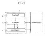
- a portable dosing apparatus (1) for continuously dosing a body with a solution at a dispensing rate that can be variedcomprises, according to the present invention, a tank unit (2) for holding the solution, a pump unit (3) for pumping the solution from the tank unit to the body, and a controller (4) for controlling the pump unit, configured such that the tank unit, pump unit, and controller each being freely connectable and disconnectable.
- the dispensing ratecan be changed simply by changing the controller.
- the time during which dispensing is interrupted when changing the dispensing rateis extremely short.
- portable dosing apparatus of our inventionis not limited to use with humans, but can also be used with animals.
- the portable dosing apparatuscan be easily attached to the body.
- a means for securing the portable dosing apparatus to the bodysuch as wrist strap 11
- the portable dosing apparatuscan be easily attached to the body.
- Such an exemplary meansis a strap like that of a wristwatch.
- the controllertypically comprises a CPU, a reference signal generating circuit for CPU operation, and a ROM for storing a control program.
- the controller in our inventionadditionally has a dispensing parameter input means (such as buttons 41 b ) for externally inputting dispensing parameters, and a display ( 44 ) for displaying dispensing parameters so that the controller can control the pump unit according to the dispensing parameters.
- the portable dosing apparatusalso has a status information input means ( 42 ) for inputting status information indicative of a condition of the body.
- the controllercontrols the pump unit according to status information from this status information input means.
- the controllercan, using the control program stored to ROM, for example, use the supplied information to control the pump unit. As a result, dosage can be easily optimally adjusted even if a person with specialist knowledge is not present.
- the tank unit of this portable dosing apparatuspreferably has a solution tank ( 21 ) that is expandable for internally storing the solution; and a pressure applying means ( 23 ) for applying pressure to the solution tank in a direction reducing an internal volume of the solution tank so as to pressurize the solution.
- the pressure applying means ( 23 )can thus pressurize the solution in the solution tank, enabling the solution to flow easily from the solution tank.
- the load on the pump unit upon dispensingis therefore low, and solution's backflow is suppressed.
- the pump unitpreferably has an actuator driven according to a drive signal from the controller; a drive power transfer mechanism (such as gear train 34 ) for transferring drive power from the actuator; and a pump ( 33 ) for pumping solution by means of drive power transferred from the drive power transfer mechanism.
- a drive power transfer mechanismsuch as gear train 34
- pump33
- This actuatoris preferably an ultrasonic motor ( 5 ) or a piezoelectric actuator.
- the size of the pump unitis reduced and the portability of the portable dosing apparatus is improved.
- the ultrasonic motor and piezoelectric actuatorare not magnetically driven, there is substantially no chance of misoperation when close to a magnetic device. The reliability of the portable dosing apparatus is thus improved.
- the pump unitpreferably comprises an actuator driven according to a drive signal from the controller; and a pump ( 73 ) for pumping solution rotatively by means of drive power transferred directly from the actuator.
- This actuatorin this case is again preferably an ultrasonic motor ( 8 ) or a piezoelectric actuator ( 63 a ).
- the size of the pump unitis reduced and the portability of the portable dosing apparatus is improved.
- the ultrasonic motor and piezoelectric actuatorare not magnetically driven, there is substantially no chance of misoperation when close to a magnetic device. The reliability of the portable dosing apparatus is thus improved.
- the ultrasonic motor or piezoelectric actuatordirectly drive the pump unit, a power transfer mechanism is not needed, and a compact, lightweight pump unit can thus be achieved.
- the portable dosing apparatusfurther preferably comprises an operation detection means (such as rotational distance detector 37 ) for detecting pump unit operation and outputting a detection signal to the controller.
- an operation detection meanssuch as rotational distance detector 37
- the reliability of the portable dosing apparatusis yet further improved as a result of the controller controlling the pump unit while monitoring pump unit operation.
- the portable dosing apparatusadditionally has a backflow prevention means (such as ratchet 33 e ) preventing the pump unit from operating in reverse.
- a backflow prevention meanssuch as ratchet 33 e
- the backflow prevention meanssignificantly lowers the chances that the pump will operate in reverse or the solution backflow will occur.
- the reliability of the portable dosing apparatusis thus yet further improved.
- the portable dosing apparatusalso has a needle ( 12 ) for injecting solution to the body.
- FIG. 1is a block diagram of a portable dosing apparatus according to a first embodiment of the present invention
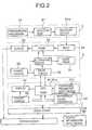
- FIG. 2is a more detailed block diagram of the portable dosing apparatus 1 shown in FIG. 1;
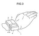
- FIGS. 3 and 4show how the portable dosing apparatus 1 is typically worn by a user
- FIG. 5is a side view of the tank unit 2 shown in FIG.
- FIG. 6is a top view of the pump unit 3 shown in FIG. 1;
- FIG. 7is a section view of an ultrasonic motor 5 that is the power source for pump unit 3 in the first embodiment shown in FIG. 1;
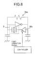
- FIG. 8is a circuit diagram of the drive signal generating circuit of ultrasonic motor 5 in the first embodiment shown in FIG. 1;
- FIG. 9is a circuit diagram of the drive state detection circuit for detecting operation of pump unit 3 in the first embodiment shown in FIG. 1;
- FIG. 10is a block diagram of the control unit 4 in the first embodiment shown in FIG. 1;
- FIG. 11Ais a top view of an alternative version of pump unit 3
- FIG. 11Bis a section view of the same;
- FIG. 12is a block diagram of a portable dosing apparatus according to a second preferred embodiment of the invention.
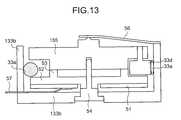
- FIG. 13is a section view of the pump 73 and ultrasonic motor 8 in the second preferred embodiment of the invention shown in FIG. 12;
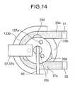
- FIG. 14is a plan view of the pump 73 and ultrasonic motor 8 in the second preferred embodiment of the invention shown in FIG. 12 .
- FIGS. 1 to 10A first preferred embodiment of a portable dosing apparatus according to the present invention is described below with reference to the accompanying FIGS. 1 to 10 .
- FIG. 1is a block diagram of this portable dosing apparatus 1 comprising a tank unit 2 , pump unit 3 , and control unit 4 .
- FIG. 2is a more detailed block diagram of the components shown in FIG. 1 .
- FIGS. 3 and 4illustrate how the portable dosing apparatus 1 is typically worn by a user.
- FIG. 5is a side view of the tank unit 2 shown in FIG. 1 .
- FIG. 6is a top view of the pump unit 3 .
- FIG. 7is a section view showing details of an ultrasonic motor 5 that is the power source for pump unit 3 .
- FIG. 8is a circuit diagram of the drive signal generating circuit 36 a of ultrasonic motor 5
- FIG. 9is a circuit diagram of the drive state detection circuit 36 b for detecting operation of pump unit 3 .
- FIG. 10is a block diagram of the control unit 4 .
- the tank unit 2 of the portable dosing apparatus 1internally holds the solution to be dispensed; the pump unit 3 dispenses the solution from tank unit 2 to the patient; and the control unit 4 controls the pump unit 3 .
- these unitsare attached to a wrist strap 11 so that they can be connected and disconnected from each other.
- control unit 4controls pump unit 3 to adjust the dispensing rate according to such patient information as the blood pressure, heart rate, and blood sugar.
- the control unit 4also monitors pump unit 3 drive status.
- solution pumped by pump unit 3is injected into the patient's body by way of needle 12 .
- tank unit 2has a bellows-like solution tank 21 disposed on a base 22 , and a pressurizing mechanism 23 whereby force can be applied so as to push down on solution tank 21 .
- Solution outlet 21 a for connecting solution tank 21 to the inlet 31 of pump unit 3 , further described below,is disposed on the bottom of solution tank 21 passing through base 22 .
- solution tank 21 shown inis FIG. 5 inflated by the solution stored therein.
- the solution in solution tank 21is thus pressurized by the force applied from pressurizing mechanism 23 and the compressive force of the solution tank 21 itself.
- pump unit 3has an inlet 31 through which solution is introduced to the pump unit 3 , an outlet 32 from which solution leaves the pump unit 3 , a pump 33 for pumping solution introduced from inlet 31 out from outlet 32 , an ultrasonic motor 5 for driving pump 33 by means of intervening gear train 34 , ultrasonic motor power source 35 , and ultrasonic motor drive circuit 36 .
- pump 33has a flexible tube 33 a connecting inlet 31 and outlet 32 disposed along the inside wall of a hollow circular container 33 b .
- a disc 33 c turned by drive power from ultrasonic motor 5is disposed coaxially to and inside circular container 33 b .
- Independently rotating rollers 33 dare disposed at 120 degree intervals around the side of disc 33 c so that the rollers 33 d press against flexible tube 33 a.
- Pump 33is thus a pump that pushes solution inside flexible tube 33 a from inlet 31 to outlet 32 as a result of rollers 33 d pushing against and rotating along the surface of flexible tube 33 a.
- a ratchet 33 e(backflow prevention means) is also disposed to disc 33 c.
- a rotational distance detector 37(operation detection means) is further disposed to one of the gears of gear train 34 .
- This rotational distance detector 37has a plurality of holes 37 a in the gear spaced at a constant angular increment, a light emitting means, and a photodiode 37 b .
- This rotational distance detector 37detects the distance of gear train 34 , that is disc 33 c , rotation, and outputs a detection signal to control unit 4 by way of drive circuit 36 .
- ultrasonic motor 5has a disc-shaped piezoelectric element 51 ; disc-shaped vibrator 52 fixed to the top of piezoelectric element 51 ; a plurality of protrusions 53 disposed integrally to the top of vibrator 52 ; a spindle 54 passing through the centers of piezoelectric element 51 and vibrator 52 and supporting them on a base; a rotor 55 supported and rotating freely on spindle 54 ; leaf spring 56 urging rotor 55 against protrusions 53 ; and lead 57 for transmitting a drive signal from drive circuit 36 to piezoelectric element 51 .
- rotor 55has on top a gear 55 a that meshes with gear train 34 .
- piezoelectric element 51is divided circumferentially into, for example, six parts, these parts being alternately polarized oppositely and divided each in two equal parts.
- the protrusions 53are disposed at the border between these polarized segments such that one protrusion 53 is located at every other polarized segment.
- This ultrasonic motor 5converts electrical energy directly into mechanical energy, features high output per unit volume, and is resistant to effects from a magnetic field.
- the drive circuit 36comprises a drive signal generating circuit 36 a as shown in FIG. 8, and a drive state detection circuit 36 b as shown in FIG. 9 .
- the drive signal generating circuit 36 ais a common self-oscillation circuit as generally used in ultrasonic motor drive circuits.
- Tri-state buffer 36 c for drive signal outputis controlled by control unit 4 .
- Drive state detection circuit 36 bamplifies and outputs a signal detected by photodiode 37 b based on a signal generated by light emitting means 37 c , which may be an LED. Drive state detection circuit 36 b is turned on and off by control unit 4 .
- control unit 4has a CPU 41 for directly controlling drive circuit 36 ; ROM 41 a to which a control program is prestored; dispensing parameter input means 41 c such as buttons 41 b for inputting a user-generated signal to CPU 41 ; reference signal generator 43 for generating a reference signal for driving CPU 41 ; display 44 for displaying the dispensing rate, dose, and biological information as controlled by CPU 41 ; and power source 45 .
- a status information input means 42can also be provided for inputting to CPU 41 a signal indicative of the patient condition.
- display 44consists basically of an LCD panel 44 a and LCD driver 44 b .
- CPU 41has a plurality of buttons 41 b as the dispensing parameter input means, including an on/off button, dispensing rate adjusting button, and an interval adjustment button.
- CPU 41controls ultrasonic motor 5 according to a signal input from buttons 41 b and status information input means 42 to adjust the dosage (volume) and dispensing rate.
- the dosage and dispensing ratecan be adjusted while confirming the dispensing conditions on display 44 . It is also possible to replace only the control unit 4 to adjust the dispensing conditions. As a result, it is not necessary to remove or replace any part of the dispensing path in order to change the dispensing conditions. Dispensing the solution is interrupted for only a very short time when changing the dispensing rate.
- control unit 4can automatically adjust dispensing conditions according to patient information detected and supplied from status information input means 42 .
- the load on ultrasonic motor 5is small because pressurizing mechanism 23 and solution tank 21 both pressurize the solution in solution tank 21 , and the solution is thus able to flow easily from the solution tank 21 .
- the ultrasonic motor 5is not magnetically driven there is substantially no possibility of misoperation when close to a magnetic device, that is, when exposed to a magnetic field. The reliability of the portable dosing apparatus 1 is thereby further improved.
- the control unit 4can also control pump unit 3 while monitoring the pump unit 3 operating status by means of rotational distance detector 37 and drive state detection circuit 36 b .
- Pump unit 3is also prevented by the ratchet 33 e from operating in reverse, thereby yet further improving the reliability of the portable dosing apparatus 1 .
- the portable dosing apparatus 2uses the pump unit 7 shown in FIGS. 12 to 14 in place of the pump unit 3 of the first embodiment.
- FIG. 12is a detailed block diagram of this portable dosing apparatus 122
- FIG. 13is a section view of the pump unit 7
- FIG. 14is a plan view of the pump unit 7 .
- Pump unit 3 and pump unit 7differ in that whereas pump unit 3 comprises ultrasonic motor 5 , outlet 32 , inlet 31 , gear train 34 , drive circuit 36 , power source 35 , and pump 33 , and pump 33 is driven by ultrasonic motor 5 by way of gear train 34 , pump unit 7 does not have a gear train 34 .
- the ultrasonic motor 8 used in pump unit 7 in place of ultrasonic motor 5directly drives pump 73 , which replaces pump 33 .
- pump unit 7comprises inlet 31 and outlet 32 , pump 73 for pumping solution in from inlet 31 and out from outlet 32 , ultrasonic motor 8 for directly driving pump 73 , power source 35 for ultrasonic motor 8 , and ultrasonic motor drive circuit 36 .
- pump 73has a flexible tube 33 a connecting inlet 31 and outlet 32 disposed along the inside wall of a hollow circular container 133 b .
- ultrasonic motor 8is disposed in circular container 133 b so that the motor rotor 155 is concentric to circular container 133 b .
- Independently rotating rollers 33 dare disposed at 120 degree intervals around the side of rotor 155 so that the rollers 33 d press against flexible tube 33 a . It should be noted that rotor 155 and ultrasonic motor 8 are not contained in pump 73 , and are further described below.
- Pump 73is thus a pump that pushes solution inside flexible tube 33 a from inlet 31 to outlet 32 as a result of rollers 33 d pushing against and rotating along the surface of flexible tube 33 a.
- a plurality of reflectors 137 aare disposed at a constant angular interval around rotor 155 on the side thereof opposite the surface that contacts protrusions 53 .
- the rotational distance detector 37(operation detection means) comprising a light emitting means and photodiode 37 b is disposed above reflectors 137 a with a specific gap therebetween. The rotational distance detector 37 thus detects the distance of rotor 155 rotation, and supplies a corresponding detection signal to control unit 4 by way of drive circuit 36 .
- the ultrasonic motor 8has a disc-shaped piezoelectric element 51 ; disc-shaped vibrator 52 fixed to the top of piezoelectric element 51 ; a plurality of protrusions 53 disposed integrally to the top of vibrator 52 ; a spindle 54 passing through the centers of piezoelectric element 51 and vibrator 52 and supporting them on a base; rotor 155 supported and rotating freely on spindle 54 ; leaf spring 56 urging rotor 155 against protrusions 53 ; and lead 57 for transmitting a drive signal from drive circuit 36 to piezoelectric element 51 .
- rollers 33 dare disposed to rotor 155 in this exemplary embodiment.
- pump 73can be driven directly by ultrasonic motor 8 .
- pump unit 7can be effectively downsized. Assembly is also simplified, and manufacturing cost is reduced, because the number of parts is also reduced.
- a pump unit 6 shown in FIG. 11can be used in place of pump unit 3 .
- pump unit 6has inlet 61 , outlet 62 and a storage compartment 63 .
- Inlet 61 and outlet 62open and close by means of a piezoelectric actuator 61 a , 62 a , respectively.
- a storage compartment 63 connected to inlet 61 and outlet 62temporarily stores solution.
- This pump unit 6is driven by a piezoelectric actuator driver 64 .
- a piezoelectric actuator 63 ais also disposed to one side of storage compartment 63 . Piezoelectric actuator 63 a can be driven to expand or contract itself, thus to change and adjust the capacity of storage compartment 63 .
- pump unit 6operates by opening only inlet 61 , expanding storage compartment 63 to draw solution therein, then closing inlet 61 and opening outlet 62 , and then compressing (contracting) storage compartment 63 to propel solution from outlet 62 .
- the benefits described abovecan also be achieved with this pump unit 6 .
- a portable dosing apparatuscan also be achieved using a motor that is driven using magnetic flux, and the type of motor or actuator used with our invention is therefore not specifically limited.
- the ultrasonic motorcan use a rectangular, annular, or other shape of vibrator.
- the drive principlecan use a standing wave or progressive wave. The shape or operating principle of the ultrasonic motor shall therefore not be specifically limited.
- controllerdirectly adjusts the dispensing conditions according to patient (biological) information, dosage can be easily optimally adjusted even if a person with specialized knowledge is not present.
- the load on the pump unitis also low because the solution in the solution tank is pressurized by a pressure applying means and can thus flow easily from the solution tank.
- the size of the pump unitis reduced and the portability of the portable dosing apparatus is improved if a compact ultrasonic motor or piezoelectric actuator with high output per unit volume is used as the drive source for the pump unit.
- the ultrasonic motor and piezoelectric actuatorare not magnetically driven, there is substantially no chance of misoperation when close to a magnetic device. The reliability of the portable dosing apparatus is thus improved.
- the ultrasonic motor or piezoelectric actuatordirectly drive the pump unit, a power transfer mechanism is not needed, and a compact, lightweight pump unit can thus be achieved.
- the reliability of the portable dosing apparatusis yet further improved as a result of the controller controlling the pump unit while monitoring pump unit operation, and a backflow prevention means significantly lowers the chances that the pump will operate in reverse or the solution backflow will occur.
Landscapes
- Health & Medical Sciences (AREA)
- Vascular Medicine (AREA)
- Engineering & Computer Science (AREA)
- Anesthesiology (AREA)
- Biomedical Technology (AREA)
- Heart & Thoracic Surgery (AREA)
- Hematology (AREA)
- Life Sciences & Earth Sciences (AREA)
- Animal Behavior & Ethology (AREA)
- General Health & Medical Sciences (AREA)
- Public Health (AREA)
- Veterinary Medicine (AREA)
- Infusion, Injection, And Reservoir Apparatuses (AREA)
- External Artificial Organs (AREA)
Abstract
Description
1. Field of the Invention
The present invention relates to a portable dosing apparatus that is capable of continuously dispensing a solution and varying the dispensing rate.
2. Description of Related Art
Portable drug dispensers that are worn by the patient and for dosing the patient with a drug are needed so that the patient can go about his or her normal daily activities while keeping his symptoms under control. Portable drug dispensers of this type include, for example, the compact peristaltic pump taught in Japanese Patent Publication Laid-Open No. 280763/1990, and the infusion pump taught in Japanese Patent Publication Laid-Open No. 236558/1987.
The peristaltic pump taught in Japanese Patent Publication Laid-Open No. 280763/1990 has a first module that is a pump module containing the injectable solution, and a second module that is a motor module containing both a controller and motor. Both the first and second modules can be installed and removed.
The infusion pump taught in Japanese Patent Publication Laid-Open No. 236558/1987 is an integrated unit, but the speed of the motor that is the source of pump drive power can be set manually, and the dispensing rate is therefore adjustable.
The operating cost of this type of portable dosing apparatus should be low because it is used daily by the patient. It is also necessary to be able to adjust the dosing rate according to the patient's symptoms.
The dosing rate of the above-noted peristaltic pump, however, is determined by the motor module, and the motor module must therefore be replaced to change the dispensing rate. However, because the motor module is part of the solution delivery path, replacing the motor module to adjust the dispensing rate means that dosing stops temporarily. Plural motor modules must therefore be provided if the dispensing rate is to be adjustable, and the cost therefore rises.
While the dispensing rate is adjustable with the above-noted infusion pump, integration of all components into a single unit means that the entire unit must be replaced when the solution runs out. Dosing is therefore interrupted for a relatively long period of time, and operating cost is high.
Both of the prior art devices described above are also powered by a motor using magnetic flux as the drive power source, thus making the power unit larger and reducing device portability. What's more, the magnetic field generated by magnetic resonance imaging (MRI) and other magnetic medical devices could cause the power unit to be misoperated.
An object of the present invention is therefore to provide a low cost portable dosing apparatus with an adjustable dispensing rate that is capable of continuous dispensing even while changing the dispensing rate.
A further object of the present invention is to provide a portable dosing apparatus that uses a motor that does not use magnetic flux, as the drive power source, and thereby achieves greater compactness and increased reliability.
To achieve the above objects, a portable dosing apparatus (1) for continuously dosing a body with a solution at a dispensing rate that can be varied comprises, according to the present invention, a tank unit (2) for holding the solution, a pump unit (3) for pumping the solution from the tank unit to the body, and a controller (4) for controlling the pump unit, configured such that the tank unit, pump unit, and controller each being freely connectable and disconnectable.
Thus comprised, the dispensing rate can be changed simply by changing the controller. In other words, because it is not necessary to replace any part of the solution dispensing path in order to change the dispensing rate, the time during which dispensing is interrupted when changing the dispensing rate is extremely short.
Furthermore, it is only necessary to replace the tank unit when the solution runs out. In addition, the relatively high cost but same pump unit is used for a specific period of time. Operating cost is therefore low.
It will also be noted that the portable dosing apparatus of our invention is not limited to use with humans, but can also be used with animals.
Furthermore, by further providing a means for securing the portable dosing apparatus to the body, such aswrist strap 11, the portable dosing apparatus can be easily attached to the body. Such an exemplary means is a strap like that of a wristwatch.
The controller typically comprises a CPU, a reference signal generating circuit for CPU operation, and a ROM for storing a control program. The controller in our invention, however, additionally has a dispensing parameter input means (such asbuttons 41b) for externally inputting dispensing parameters, and a display (44) for displaying dispensing parameters so that the controller can control the pump unit according to the dispensing parameters.
It is yet further possible to adjust the dosage, dispensing rate, and other dispensing conditions while confirming the information on a display. It is therefore possible to easily and reliably change the dispensing parameters without replacing the controller.
Yet further preferably, the portable dosing apparatus also has a status information input means (42) for inputting status information indicative of a condition of the body. In this case the controller controls the pump unit according to status information from this status information input means.
If such patient information as the heart rate, blood pressure, blood sugar, is entered, the controller can, using the control program stored to ROM, for example, use the supplied information to control the pump unit. As a result, dosage can be easily optimally adjusted even if a person with specialist knowledge is not present.
The tank unit of this portable dosing apparatus preferably has a solution tank (21) that is expandable for internally storing the solution; and a pressure applying means (23) for applying pressure to the solution tank in a direction reducing an internal volume of the solution tank so as to pressurize the solution.
The pressure applying means (23) can thus pressurize the solution in the solution tank, enabling the solution to flow easily from the solution tank. The load on the pump unit upon dispensing is therefore low, and solution's backflow is suppressed.
The pump unit preferably has an actuator driven according to a drive signal from the controller; a drive power transfer mechanism (such as gear train34) for transferring drive power from the actuator; and a pump (33) for pumping solution by means of drive power transferred from the drive power transfer mechanism.
This actuator is preferably an ultrasonic motor (5) or a piezoelectric actuator.
By using a compact ultrasonic motor or piezoelectric actuator with high output per unit volume as the drive source for the pump unit, the size of the pump unit is reduced and the portability of the portable dosing apparatus is improved.
Furthermore, because the ultrasonic motor and piezoelectric actuator are not magnetically driven, there is substantially no chance of misoperation when close to a magnetic device. The reliability of the portable dosing apparatus is thus improved.
Further, the pump unit preferably comprises an actuator driven according to a drive signal from the controller; and a pump (73) for pumping solution rotatively by means of drive power transferred directly from the actuator.
This actuator in this case is again preferably an ultrasonic motor (8) or a piezoelectric actuator (63a).
By using a compact ultrasonic motor or piezoelectric actuator with high output per unit volume as the drive source for the pump unit, the size of the pump unit is reduced and the portability of the portable dosing apparatus is improved.
Furthermore, because the ultrasonic motor and piezoelectric actuator are not magnetically driven, there is substantially no chance of misoperation when close to a magnetic device. The reliability of the portable dosing apparatus is thus improved.
Furthermore, because the ultrasonic motor or piezoelectric actuator directly drive the pump unit, a power transfer mechanism is not needed, and a compact, lightweight pump unit can thus be achieved.
Furthermore, the number of the parts is reduced, thus minimizing the manufacturing cost.
The portable dosing apparatus further preferably comprises an operation detection means (such as rotational distance detector37) for detecting pump unit operation and outputting a detection signal to the controller.
The reliability of the portable dosing apparatus is yet further improved as a result of the controller controlling the pump unit while monitoring pump unit operation.
Yet further preferably, the portable dosing apparatus additionally has a backflow prevention means (such asratchet 33e) preventing the pump unit from operating in reverse.
In this case the backflow prevention means significantly lowers the chances that the pump will operate in reverse or the solution backflow will occur. The reliability of the portable dosing apparatus is thus yet further improved.
Yet further preferably, the portable dosing apparatus also has a needle (12) for injecting solution to the body.
Other objects and attainments together with a fuller understanding of the invention will become apparent and appreciated by referring to the following description and claims taken in conjunction with the accompanying drawings.
FIG. 1 is a block diagram of a portable dosing apparatus according to a first embodiment of the present invention;
FIG. 2 is a more detailed block diagram of theportable dosing apparatus 1 shown in FIG. 1;
FIGS. 3 and 4 show how theportable dosing apparatus 1 is typically worn by a user;
FIG. 5 is a side view of thetank unit 2 shown in FIG.
FIG. 6 is a top view of thepump unit 3 shown in FIG. 1;
FIG. 7 is a section view of anultrasonic motor 5 that is the power source forpump unit 3 in the first embodiment shown in FIG. 1;
FIG. 8 is a circuit diagram of the drive signal generating circuit ofultrasonic motor 5 in the first embodiment shown in FIG. 1;
FIG. 9 is a circuit diagram of the drive state detection circuit for detecting operation ofpump unit 3 in the first embodiment shown in FIG. 1;
FIG. 10 is a block diagram of thecontrol unit 4 in the first embodiment shown in FIG. 1;
FIG. 11A is a top view of an alternative version ofpump unit 3, and FIG. 11B is a section view of the same;
FIG. 12 is a block diagram of a portable dosing apparatus according to a second preferred embodiment of the invention;
FIG. 13 is a section view of thepump 73 andultrasonic motor 8 in the second preferred embodiment of the invention shown in FIG. 12; and
FIG. 14 is a plan view of thepump 73 andultrasonic motor 8 in the second preferred embodiment of the invention shown in FIG.12.
A first preferred embodiment of a portable dosing apparatus according to the present invention is described below with reference to the accompanying FIGS. 1 to10.
FIG. 1 is a block diagram of thisportable dosing apparatus 1 comprising atank unit 2, pumpunit 3, andcontrol unit 4. FIG. 2 is a more detailed block diagram of the components shown in FIG.1.
FIGS. 3 and 4 illustrate how theportable dosing apparatus 1 is typically worn by a user.
FIG. 5 is a side view of thetank unit 2 shown in FIG.1. FIG. 6 is a top view of thepump unit 3. FIG. 7 is a section view showing details of anultrasonic motor 5 that is the power source forpump unit 3. FIG. 8 is a circuit diagram of the drivesignal generating circuit 36aofultrasonic motor 5, and FIG. 9 is a circuit diagram of the drivestate detection circuit 36bfor detecting operation ofpump unit 3. FIG. 10 is a block diagram of thecontrol unit 4.
Referring to FIG. 1, thetank unit 2 of theportable dosing apparatus 1 internally holds the solution to be dispensed; thepump unit 3 dispenses the solution fromtank unit 2 to the patient; and thecontrol unit 4 controls thepump unit 3. As shown in FIGS. 2,3, and4, these units are attached to awrist strap 11 so that they can be connected and disconnected from each other.
As described more fully below, thecontrol unit 4 controls pumpunit 3 to adjust the dispensing rate according to such patient information as the blood pressure, heart rate, and blood sugar. Thecontrol unit 4 also monitorspump unit 3 drive status.
As shown in FIG. 4, solution pumped bypump unit 3 is injected into the patient's body by way ofneedle 12.
As shown in FIG.2 and FIG. 5,tank unit 2 has a bellows-like solution tank 21 disposed on abase 22, and apressurizing mechanism 23 whereby force can be applied so as to push down onsolution tank 21.
It should be noted thatsolution tank 21 shown in is FIG. 5 inflated by the solution stored therein. The solution insolution tank 21 is thus pressurized by the force applied from pressurizingmechanism 23 and the compressive force of thesolution tank 21 itself.
As shown in FIG.2 and FIG. 6, pumpunit 3 has aninlet 31 through which solution is introduced to thepump unit 3, anoutlet 32 from which solution leaves thepump unit 3, apump 33 for pumping solution introduced frominlet 31 out fromoutlet 32, anultrasonic motor 5 for drivingpump 33 by means of interveninggear train 34, ultrasonicmotor power source 35, and ultrasonicmotor drive circuit 36.
As shown in FIG. 6, pump33 has aflexible tube 33aconnectinginlet 31 andoutlet 32 disposed along the inside wall of a hollowcircular container 33b. A disc33cturned by drive power fromultrasonic motor 5 is disposed coaxially to and insidecircular container 33b. Independently rotatingrollers 33dare disposed at 120 degree intervals around the side of disc33cso that therollers 33dpress againstflexible tube 33a.
To mechanically prevent disc33cfrom rotating in the opposite direction, aratchet 33e(backflow prevention means) is also disposed to disc33c.
A rotational distance detector37 (operation detection means) is further disposed to one of the gears ofgear train 34. This rotational distance detector37 has a plurality ofholes 37ain the gear spaced at a constant angular increment, a light emitting means, and aphotodiode 37b. This rotational distance detector37 detects the distance ofgear train 34, that is disc33c, rotation, and outputs a detection signal to controlunit 4 by way ofdrive circuit 36.
As shown in FIG. 7,ultrasonic motor 5 has a disc-shapedpiezoelectric element 51; disc-shapedvibrator 52 fixed to the top ofpiezoelectric element 51; a plurality ofprotrusions 53 disposed integrally to the top ofvibrator 52; aspindle 54 passing through the centers ofpiezoelectric element 51 andvibrator 52 and supporting them on a base; arotor 55 supported and rotating freely onspindle 54;leaf spring 56 urgingrotor 55 againstprotrusions 53; and lead57 for transmitting a drive signal fromdrive circuit 36 topiezoelectric element 51.
It should be noted thatrotor 55 has on top agear 55athat meshes withgear train 34. In addition,piezoelectric element 51 is divided circumferentially into, for example, six parts, these parts being alternately polarized oppositely and divided each in two equal parts. Theprotrusions 53 are disposed at the border between these polarized segments such that oneprotrusion 53 is located at every other polarized segment.
Thisultrasonic motor 5 converts electrical energy directly into mechanical energy, features high output per unit volume, and is resistant to effects from a magnetic field.
Thedrive circuit 36 comprises a drivesignal generating circuit 36aas shown in FIG. 8, and a drivestate detection circuit 36bas shown in FIG.9.
The drivesignal generating circuit 36ais a common self-oscillation circuit as generally used in ultrasonic motor drive circuits.Tri-state buffer 36cfor drive signal output is controlled bycontrol unit 4.
Drivestate detection circuit 36bamplifies and outputs a signal detected byphotodiode 37bbased on a signal generated by light emitting means37c, which may be an LED. Drivestate detection circuit 36bis turned on and off bycontrol unit 4.
As shown in FIG.2 and FIG. 10,control unit 4 has a CPU41 for directly controllingdrive circuit 36;ROM 41ato which a control program is prestored; dispensing parameter input means41csuch asbuttons 41bfor inputting a user-generated signal to CPU41;reference signal generator 43 for generating a reference signal for driving CPU41;display 44 for displaying the dispensing rate, dose, and biological information as controlled by CPU41; andpower source 45.
A status information input means42 can also be provided for inputting toCPU 41 a signal indicative of the patient condition.
As shown in FIG. 10,display 44 consists basically of anLCD panel 44aandLCD driver 44b. CPU41 has a plurality ofbuttons 41bas the dispensing parameter input means, including an on/off button, dispensing rate adjusting button, and an interval adjustment button.
Following the control program stored toROM 41a, CPU41 controlsultrasonic motor 5 according to a signal input frombuttons 41band status information input means42 to adjust the dosage (volume) and dispensing rate.
When the solution is consumed and must be replenished with theportable dosing apparatus 1 described above, it is only necessary to replacetank unit 2. Operating cost is therefore low.
Furthermore, the dosage and dispensing rate can be adjusted while confirming the dispensing conditions ondisplay 44. It is also possible to replace only thecontrol unit 4 to adjust the dispensing conditions. As a result, it is not necessary to remove or replace any part of the dispensing path in order to change the dispensing conditions. Dispensing the solution is interrupted for only a very short time when changing the dispensing rate.
The dosage can also be easily adjusted to be optimum even when a person with specialized knowledge is not present becausecontrol unit 4 can automatically adjust dispensing conditions according to patient information detected and supplied from status information input means42.
Furthermore, the load onultrasonic motor 5 is small because pressurizingmechanism 23 andsolution tank 21 both pressurize the solution insolution tank 21, and the solution is thus able to flow easily from thesolution tank 21.
Yet further, by using a compactultrasonic motor 5 featuring high output per unit volume as the drive source forpump unit 3, the size of the pump unit is reduced and the portability of the portable dosing apparatus is thereby improved.
Yet further, because theultrasonic motor 5 is not magnetically driven there is substantially no possibility of misoperation when close to a magnetic device, that is, when exposed to a magnetic field. The reliability of theportable dosing apparatus 1 is thereby further improved.
Thecontrol unit 4 can also controlpump unit 3 while monitoring thepump unit 3 operating status by means of rotational distance detector37 and drivestate detection circuit 36b.Pump unit 3 is also prevented by theratchet 33efrom operating in reverse, thereby yet further improving the reliability of theportable dosing apparatus 1.
Theportable dosing apparatus 2 according to this second embodiment of the invention uses thepump unit 7 shown in FIGS. 12 to14 in place of thepump unit 3 of the first embodiment. FIG. 12 is a detailed block diagram of this portable dosing apparatus122, FIG. 13 is a section view of thepump unit 7, and FIG. 14 is a plan view of thepump unit 7.
It should be noted that like parts in this second embodiment and the first embodiment described above are identified by like reference numeral, and further description thereof is thus omitted below.
This is described in further detail below.
As shown in FIG. 12, FIG. 13, and FIG. 14,pump unit 7 comprisesinlet 31 andoutlet 32, pump73 for pumping solution in frominlet 31 and out fromoutlet 32,ultrasonic motor 8 for directly drivingpump 73,power source 35 forultrasonic motor 8, and ultrasonicmotor drive circuit 36.
As shown in FIG. 14, pump73 has aflexible tube 33aconnectinginlet 31 andoutlet 32 disposed along the inside wall of a hollowcircular container 133b.ultrasonic motor 8 is disposed incircular container 133bso that themotor rotor 155 is concentric tocircular container 133b. Independently rotatingrollers 33dare disposed at 120 degree intervals around the side ofrotor 155 so that therollers 33dpress againstflexible tube 33a. It should be noted thatrotor 155 andultrasonic motor 8 are not contained inpump 73, and are further described below.
A plurality ofreflectors 137aare disposed at a constant angular interval aroundrotor 155 on the side thereof opposite the surface that contacts protrusions53. The rotational distance detector37 (operation detection means) comprising a light emitting means andphotodiode 37bis disposed abovereflectors 137awith a specific gap therebetween. The rotational distance detector37 thus detects the distance ofrotor 155 rotation, and supplies a corresponding detection signal to controlunit 4 by way ofdrive circuit 36.
As shown in FIG. 13, theultrasonic motor 8 has a disc-shapedpiezoelectric element 51; disc-shapedvibrator 52 fixed to the top ofpiezoelectric element 51; a plurality ofprotrusions 53 disposed integrally to the top ofvibrator 52; aspindle 54 passing through the centers ofpiezoelectric element 51 andvibrator 52 and supporting them on a base;rotor 155 supported and rotating freely onspindle 54;leaf spring 56 urgingrotor 155 againstprotrusions 53; and lead57 for transmitting a drive signal fromdrive circuit 36 topiezoelectric element 51. It will be remembered thatrollers 33dare disposed torotor 155 in this exemplary embodiment.
By thus disposingrollers 33dtorotor 155 and placing theflexible tube 33aaround the outside ofrotor 155 so that it is squeezed betweenrollers 33dandcircular container 133b, pump73 can be driven directly byultrasonic motor 8. By thus eliminatinggear train 34,pump unit 7 can be effectively downsized. Assembly is also simplified, and manufacturing cost is reduced, because the number of parts is also reduced.
It will also be obvious to one with ordinary skill in the related art that the present invention shall not be limited to the above described preferred embodiments and can be varied in many ways without departing from the scope of the accompanying claims.
For example, apump unit 6 shown in FIG. 11 can be used in place ofpump unit 3.
As shown in the plan view in FIG.11A and the section view in FIG. 11B,pump unit 6 hasinlet 61,outlet 62 and astorage compartment 63.Inlet 61 andoutlet 62 open and close by means of apiezoelectric actuator storage compartment 63 connected toinlet 61 andoutlet 62 temporarily stores solution. Thispump unit 6 is driven by apiezoelectric actuator driver 64.
Apiezoelectric actuator 63ais also disposed to one side ofstorage compartment 63.Piezoelectric actuator 63acan be driven to expand or contract itself, thus to change and adjust the capacity ofstorage compartment 63.
In other words, pumpunit 6 operates by openingonly inlet 61, expandingstorage compartment 63 to draw solution therein, then closinginlet 61 andopening outlet 62, and then compressing (contracting)storage compartment 63 to propel solution fromoutlet 62. The benefits described above can also be achieved with thispump unit 6.
It should be noted that other than making the portable dosing apparatus larger and more susceptible to the effects of magnetic fields, a portable dosing apparatus according to our invention can also be achieved using a motor that is driven using magnetic flux, and the type of motor or actuator used with our invention is therefore not specifically limited.
Furthermore, while a disc shaped ultrasonic motor is used in these embodiments as the ultrasonic motor, the invention shall obviously not be so limited. For example, the ultrasonic motor can use a rectangular, annular, or other shape of vibrator. In addition, the drive principle can use a standing wave or progressive wave. The shape or operating principle of the ultrasonic motor shall therefore not be specifically limited.
As described above, operating cost is low because it is only necessary to replace the tank unit when the solution runs out.
It is also possible to replace only the pump unit to, for example, change the type of solution, sterilize, or repair the pump unit.
It is yet further possible to adjust the dosage, dispensing rate, and other dispensing conditions while confirming the information on a display and also by replacing only the controller. It is therefore not necessary to change any parts of the solution delivery path when changing the dispensing conditions.
The time that dispensing is interrupted when changing the dispensing rate is therefore extremely short.
Furthermore, because the controller directly adjusts the dispensing conditions according to patient (biological) information, dosage can be easily optimally adjusted even if a person with specialized knowledge is not present.
The load on the pump unit is also low because the solution in the solution tank is pressurized by a pressure applying means and can thus flow easily from the solution tank.
Furthermore, the size of the pump unit is reduced and the portability of the portable dosing apparatus is improved if a compact ultrasonic motor or piezoelectric actuator with high output per unit volume is used as the drive source for the pump unit.
Furthermore, because the ultrasonic motor and piezoelectric actuator are not magnetically driven, there is substantially no chance of misoperation when close to a magnetic device. The reliability of the portable dosing apparatus is thus improved.
Furthermore, because the ultrasonic motor or piezoelectric actuator directly drive the pump unit, a power transfer mechanism is not needed, and a compact, lightweight pump unit can thus be achieved.
The number of parts is also reduced and manufacturing cost can therefore be kept down.
The reliability of the portable dosing apparatus is yet further improved as a result of the controller controlling the pump unit while monitoring pump unit operation, and a backflow prevention means significantly lowers the chances that the pump will operate in reverse or the solution backflow will occur.
Although the present invention has been described in connection with the preferred embodiments thereof with reference to the accompanying drawings, it is to be noted that various changes and modifications will be apparent to those skilled in the art. Such changes and modifications are to be understood as included within the scope of the present invention as defined by the appended claims, unless they depart there from.
Claims (29)
1. A portable solution delivery apparatus for supplying a body with a solution at a dispensing rate that can be varied, comprising:
a tank unit for holding the solution;
a pump unit for pumping the solution from the tank unit to the body;
a controller for controlling the pump unit; and
a housing in which the tank unit, the pumping unit, and the controller are removably disposed, the housing being removably mountable to the body.
2. A portable solution delivery apparatus according toclaim 1 ; further comprising operation detection means for detecting pump unit operation and outputting a detection signal to the controller.
3. A portable solution delivery apparatus according toclaim 1 ; wherein the controller comprises dispensing parameter input means for externally inputting a dispensing parameter; and a display for displaying a dispensing parameter; and wherein the controller controls the pump unit according to the input dispensing parameter.
4. A portable solution delivery apparatus according toclaim 1 ; further comprising status information input means for inputting status information indicative of a condition of the body; wherein the controller controls the pump unit according to status information from the status information input means.
5. A portable solution delivery apparatus according toclaim 1 ; wherein the tank unit comprises a solution tank that is expandable for internally storing the solution; and pressure applying means for applying pressure to the solution tank so as to reduce an internal volume of the solution tank so as to pressurize the solution.
6. A portable solution delivery apparatus according toclaim 1 ; wherein the pump unit comprises an actuator driven according to a drive signal from the controller; a drive power transfer mechanism for transferring drive power from the actuator; and a pump for pumping solution by means of drive power transferred from the drive power transfer mechanism.
7. A portable solution delivery apparatus according toclaim 6 ; wherein the actuator is an ultrasonic motor.
8. A portable solution delivery apparatus according toclaim 6 ; wherein the actuator is a piezoelectric actuator.
9. A portable solution delivery apparatus according toclaim 6 ; wherein the pump unit further comprises a ratchet mechanism connected to one of the drive power transfer mechanism and the pump for preventing backflow of the drive power.
10. A portable solution delivery apparatus according toclaim 1 ; wherein the pump unit comprises an actuator driven according to a drive signal from the controller; and a pump for pumping solution by means of drive power transferred from the actuator.
11. A portable solution delivery apparatus according toclaim 10 ; wherein the actuator is an ultrasonic motor.
12. A portable solution delivery apparatus according toclaim 10 ; wherein the actuator is a piezoelectric actuator.
13. A portable solution delivery apparatus according toclaim 10 ; wherein the pump unit further comprises a ratchet mechanism connected to the pump for preventing backflow of the drive power.
14. A portable solution delivery apparatus according toclaim 1 ; further comprising backflow prevention means for preventing the pump unit from operating in reverse.
15. A portable solution delivery apparatus according toclaim 1 ; further comprising a needle disposed in a flow path of the solution for injecting solution into the body.
16. A portable solution delivery apparatus for delivering a solution to a body, comprising: a tank for holding the solution; a storage compartment having a path therein through which the solution is pumped; a piezoelectric actuator disposed in the storage compartment for pumping the solution by changing the capacity of the storage compartment by undergoing expanding and contracting movement; and a controller for controlling the piezoelectric actuator.
17. A portable solution delivery apparatus according toclaim 16 ; wherein the controller comprises dispensing parameter input means for externally inputting a dispensing parameter; and a display for displaying a dispensing parameter; and wherein the controller controls the piezoelectric actuator according to the input dispensing parameter.
18. A portable solution delivery apparatus according toclaim 16 ; further comprising status information input means for inputting status information indicative of a condition of the body; wherein the controller controls the piezoelectric actuator according to the status information.
19. A portable solution deliver apparatus according toclaim 16 ; further comprising a needle provided in the flow path for injecting the solution into the body.
20. A portable solution delivery apparatus for delivering a solution to a body, comprising: a housing removably mountable to the body; a tank disposed in the housing for holding the solution; a pump unit disposed in the housing for pumping the solution from the tank to the body; a controller removably disposed in the housing for controlling the pump unit to deliver the solution at a desired dispensing rate; and a delivery device for supplying the solution to a desired part of the body; wherein the controller is removable and replaceable by another controller to change the dispensing rate of the solution.
21. A portable solution delivery apparatus according toclaim 20 ; wherein the controller comprises dispensing parameter input means for externally inputting a dispensing parameter; and a display for displaying a dispensing parameter; wherein the controller controls the pump unit according to the input dispensing parameter.
22. A portable solution delivery apparatus according toclaim 20 ; further comprising status information input means for inputting status information indicative of a condition of the body; wherein the controller controls the pump unit according to status information from the status information input means.
23. A portable solution delivery apparatus according toclaim 20 ; wherein the tank unit comprises a solution tank that is expandable for internally storing the solution; and pressure applying means for applying pressure to the solution tank to reduce an internal volume of the solution tank so as to pressurize the solution.
24. A portable solution delivery apparatus according toclaim 20 ; wherein the pump unit comprises an actuator driven according to a drive signal from the controller; a drive power transfer mechanism for transferring drive power from the actuator; and a pump for pumping solution by means of drive power transferred from the drive power transfer mechanism.
25. A portable solution delivery apparatus according toclaim 24 ; wherein the actuator is an ultrasonic motor.
26. A portable solution delivery apparatus according toclaim 24 ; wherein the actuator is a piezoelectric actuator.
27. A portable solution delivery apparatus according toclaim 20 ; further comprising operation detection means for detecting pump unit operation and outputting a detection signal to the controller.
28. A portable solution delivery apparatus according toclaim 20 ; further comprising backflow prevention means for preventing the pump unit from operating in reverse.
29. A portable solution delivery apparatus according toclaim 20 ; wherein the deliver device comprises a needle disposed in a flow path of the solution for injecting the solution into the body.
Applications Claiming Priority (4)
| Application Number | Priority Date | Filing Date | Title |
|---|---|---|---|
| JP11-283448 | 1999-10-04 | ||
| JP28344899AJP2001104478A (en) | 1999-10-04 | 1999-10-04 | Portable liquid drug administration device |
| JP11-294228 | 1999-10-15 | ||
| JP29422899AJP2001115972A (en) | 1999-10-15 | 1999-10-15 | Roller-type pump |
Publications (1)
| Publication Number | Publication Date |
|---|---|
| US6659978B1true US6659978B1 (en) | 2003-12-09 |
Family
ID=29713590
Family Applications (1)
| Application Number | Title | Priority Date | Filing Date |
|---|---|---|---|
| US09/675,229Expired - LifetimeUS6659978B1 (en) | 1999-10-04 | 2000-09-29 | Portable dosing apparatus |
Country Status (1)
| Country | Link |
|---|---|
| US (1) | US6659978B1 (en) |
Cited By (89)
| Publication number | Priority date | Publication date | Assignee | Title |
|---|---|---|---|---|
| US20030163223A1 (en)* | 2002-02-28 | 2003-08-28 | Blomquist Michael L. | Programmable insulin pump |
| US20050219288A1 (en)* | 2004-04-02 | 2005-10-06 | Jim Vogeley | Piezoelectric devices and methods and circuits for driving same |
| US20050225202A1 (en)* | 2004-04-02 | 2005-10-13 | James Vogeley | Piezoelectric devices and methods and circuits for driving same |
| US20050225201A1 (en)* | 2004-04-02 | 2005-10-13 | Par Technologies, Llc | Piezoelectric devices and methods and circuits for driving same |
| US20050256388A1 (en)* | 2002-06-17 | 2005-11-17 | Susi Roger E | Non-magnetic medical infusion device |
| US20060079758A1 (en)* | 2004-10-12 | 2006-04-13 | Susi Roger E | Non-magnetic medical infusion device |
| US20060146096A1 (en)* | 2004-12-30 | 2006-07-06 | Par Technologies, Llc | Actuators with diaphragm and methods of operating same |
| US20060173412A1 (en)* | 2002-06-17 | 2006-08-03 | Susi Roger E | Liquid infusion apparatus |
| US20060245950A1 (en)* | 2004-12-30 | 2006-11-02 | Par Technologies, Llc | Actuators with connected diaphragms |
| US7220248B2 (en) | 2002-12-23 | 2007-05-22 | M2 Medical A/S | Flexible piston rod |
| US20070129681A1 (en)* | 2005-11-01 | 2007-06-07 | Par Technologies, Llc | Piezoelectric actuation of piston within dispensing chamber |
| US7232423B2 (en) | 2002-07-24 | 2007-06-19 | M2 Medical A/S | Infusion pump system, an infusion pump unit and an infusion pump |
| US20070216256A1 (en)* | 2004-04-02 | 2007-09-20 | Par Technologies, Llc | Piezoelectric devices and methods and circuits for driving same |
| WO2007038060A3 (en)* | 2005-09-26 | 2007-10-11 | M2 Medical As | Modular infusion pump having two different energy sources |
| WO2008139459A1 (en)* | 2007-05-11 | 2008-11-20 | Medingo Ltd. | Methods and apparatus for monitoring rotation of an infusion pump driving mechanism |
| US20090076461A1 (en)* | 2007-07-13 | 2009-03-19 | Iradimed Corporation | System and method for communication with an infusion device |
| US7534226B2 (en) | 2005-09-26 | 2009-05-19 | M2 Group Holdings, Inc. | Dispensing fluid from an infusion pump system |
| US20090156990A1 (en)* | 2007-12-12 | 2009-06-18 | M2 Medical Group Holdings, Inc. | Portable Infusion Pump and Media Player |
| WO2009046989A3 (en)* | 2007-10-11 | 2009-06-18 | Roche Diagnostics Gmbh | Carrier for an infusion system |
| US20090259214A1 (en)* | 2008-04-09 | 2009-10-15 | Searete Llc, A Limited Liability Corporation Of The State Of Delaware | Agent delivery device |
| US20090275887A1 (en)* | 2008-05-05 | 2009-11-05 | M2 Medical Group Holdings, Inc. | Infusion Pump System |
| US20100049164A1 (en)* | 2008-08-20 | 2010-02-25 | M2 Medical Group Holdings, Inc. | Infusion Pump Systems and Methods |
| US20100094251A1 (en)* | 2008-10-15 | 2010-04-15 | M2 Medical Group Holdings, Inc. | Infusion Pump System and Methods |
| US7713238B2 (en) | 2005-04-06 | 2010-05-11 | M2 Group Holdings, Inc. | Medicine dispensing device |
| US7717903B2 (en) | 2007-09-06 | 2010-05-18 | M2 Group Holdings, Inc. | Operating an infusion pump system |
| US20100145276A1 (en)* | 2007-08-01 | 2010-06-10 | Ofer Yodfat | Portable infusion device with means for monitoring and controlling fluid delivery |
| US20100174266A1 (en)* | 2009-01-02 | 2010-07-08 | M2 Medical Group Holdings, Inc. | Infusion Pump System and Methods |
| US7753879B2 (en) | 2004-01-29 | 2010-07-13 | M2 Group Holdings, Inc. | Disposable medicine dispensing device |
| US7785288B2 (en) | 2002-12-23 | 2010-08-31 | Asante Solutions, Inc. | Disposable, wearable insulin dispensing device, a combination of such a device and a programming controller and a method of controlling the operation of such a device |
| US7794426B2 (en) | 2007-05-21 | 2010-09-14 | Asante Solutions, Inc. | Infusion pump system with contamination-resistant features |
| US7828528B2 (en) | 2007-09-06 | 2010-11-09 | Asante Solutions, Inc. | Occlusion sensing system for infusion pumps |
| US7833196B2 (en) | 2007-05-21 | 2010-11-16 | Asante Solutions, Inc. | Illumination instrument for an infusion pump |
| US7879026B2 (en) | 2007-09-07 | 2011-02-01 | Asante Solutions, Inc. | Controlled adjustment of medicine dispensation from an infusion pump device |
| US7887511B2 (en) | 2002-11-05 | 2011-02-15 | Asante Solutions, Inc. | Disposable wearable insulin dispensing device, a combination of such a device and a programming controller and a method of controlling the operation of such a device |
| US7892199B2 (en) | 2007-05-21 | 2011-02-22 | Asante Solutions, Inc. | Occlusion sensing for an infusion pump |
| US7935105B2 (en) | 2007-09-07 | 2011-05-03 | Asante Solutions, Inc. | Data storage for an infusion pump system |
| US7935076B2 (en) | 2007-09-07 | 2011-05-03 | Asante Solutions, Inc. | Activity sensing techniques for an infusion pump system |
| US7981102B2 (en) | 2007-05-21 | 2011-07-19 | Asante Solutions, Inc. | Removable controller for an infusion pump |
| US8057436B2 (en) | 2005-09-26 | 2011-11-15 | Asante Solutions, Inc. | Dispensing fluid from an infusion pump system |
| US8105279B2 (en) | 2005-09-26 | 2012-01-31 | M2 Group Holdings, Inc. | Dispensing fluid from an infusion pump system |
| US8192394B2 (en) | 2005-11-08 | 2012-06-05 | Asante Solutions, Inc. | Method and system for manual and autonomous control of an infusion pump |
| US8287514B2 (en) | 2007-09-07 | 2012-10-16 | Asante Solutions, Inc. | Power management techniques for an infusion pump system |
| US8287495B2 (en) | 2009-07-30 | 2012-10-16 | Tandem Diabetes Care, Inc. | Infusion pump system with disposable cartridge having pressure venting and pressure feedback |
| US8372039B2 (en) | 2005-11-08 | 2013-02-12 | Asante Solutions, Inc. | Infusion pump system |
| US8409142B2 (en) | 2005-09-26 | 2013-04-02 | Asante Solutions, Inc. | Operating an infusion pump system |
| US8454557B1 (en) | 2012-07-19 | 2013-06-04 | Asante Solutions, Inc. | Infusion pump system and method |
| US8454581B2 (en) | 2011-03-16 | 2013-06-04 | Asante Solutions, Inc. | Infusion pump systems and methods |
| US8454562B1 (en) | 2012-07-20 | 2013-06-04 | Asante Solutions, Inc. | Infusion pump system and method |
| USD691258S1 (en) | 2010-05-27 | 2013-10-08 | Asante Solutions, Inc. | Infusion pump |
| US8551046B2 (en) | 2006-09-18 | 2013-10-08 | Asante Solutions, Inc. | Dispensing fluid from an infusion pump system |
| US8585657B2 (en) | 2011-06-21 | 2013-11-19 | Asante Solutions, Inc. | Dispensing fluid from an infusion pump system |
| US8808230B2 (en) | 2011-09-07 | 2014-08-19 | Asante Solutions, Inc. | Occlusion detection for an infusion pump system |
| US8852152B2 (en) | 2011-02-09 | 2014-10-07 | Asante Solutions, Inc. | Infusion pump systems and methods |
| WO2014191038A1 (en)* | 2013-05-30 | 2014-12-04 | Weibel Cds Ag | Device for dispensing a fluid to a patient |
| US9427523B2 (en) | 2012-12-10 | 2016-08-30 | Bigfoot Biomedical, Inc. | Infusion pump system and method |
| US9446187B2 (en) | 2013-06-03 | 2016-09-20 | Bigfoot Biomedical, Inc. | Infusion pump system and method |
| US9446186B2 (en) | 2013-03-01 | 2016-09-20 | Bigfoot Biomedical, Inc. | Operating an infusion pump system |
| US9457141B2 (en) | 2013-06-03 | 2016-10-04 | Bigfoot Biomedical, Inc. | Infusion pump system and method |
| US9561324B2 (en) | 2013-07-19 | 2017-02-07 | Bigfoot Biomedical, Inc. | Infusion pump system and method |
| US9629901B2 (en) | 2014-07-01 | 2017-04-25 | Bigfoot Biomedical, Inc. | Glucagon administration system and methods |
| US9669160B2 (en) | 2014-07-30 | 2017-06-06 | Tandem Diabetes Care, Inc. | Temporary suspension for closed-loop medicament therapy |
| USD809134S1 (en) | 2016-03-10 | 2018-01-30 | Bigfoot Biomedical, Inc. | Infusion pump assembly |
| US9878097B2 (en) | 2015-04-29 | 2018-01-30 | Bigfoot Biomedical, Inc. | Operating an infusion pump system |
| US9901677B2 (en) | 2012-10-16 | 2018-02-27 | Bigfoot Biomedical, Inc. | Infusion pump system and methods |
| US9919096B2 (en) | 2014-08-26 | 2018-03-20 | Bigfoot Biomedical, Inc. | Infusion pump system and method |
| US9962486B2 (en) | 2013-03-14 | 2018-05-08 | Tandem Diabetes Care, Inc. | System and method for detecting occlusions in an infusion pump |
| US10052049B2 (en) | 2008-01-07 | 2018-08-21 | Tandem Diabetes Care, Inc. | Infusion pump with blood glucose alert delay |
| US10137246B2 (en) | 2014-08-06 | 2018-11-27 | Bigfoot Biomedical, Inc. | Infusion pump assembly and method |
| USD836769S1 (en) | 2016-12-12 | 2018-12-25 | Bigfoot Biomedical, Inc. | Insulin delivery controller |
| USD839294S1 (en) | 2017-06-16 | 2019-01-29 | Bigfoot Biomedical, Inc. | Display screen with graphical user interface for closed-loop medication delivery |
| US10258736B2 (en) | 2012-05-17 | 2019-04-16 | Tandem Diabetes Care, Inc. | Systems including vial adapter for fluid transfer |
| US10357607B2 (en) | 2007-05-24 | 2019-07-23 | Tandem Diabetes Care, Inc. | Correction factor testing using frequent blood glucose input |
| US10426896B2 (en) | 2016-09-27 | 2019-10-01 | Bigfoot Biomedical, Inc. | Medicine injection and disease management systems, devices, and methods |
| US10449294B1 (en) | 2016-01-05 | 2019-10-22 | Bigfoot Biomedical, Inc. | Operating an infusion pump system |
| US10569015B2 (en) | 2013-12-02 | 2020-02-25 | Bigfoot Biomedical, Inc. | Infusion pump system and method |
| US10569016B2 (en) | 2015-12-29 | 2020-02-25 | Tandem Diabetes Care, Inc. | System and method for switching between closed loop and open loop control of an ambulatory infusion pump |
| USD911355S1 (en) | 2018-03-29 | 2021-02-23 | Bigfoot Biomedical, Inc. | Display screen or portion thereof with graphical user interface |
| US10987468B2 (en) | 2016-01-05 | 2021-04-27 | Bigfoot Biomedical, Inc. | Operating multi-modal medicine delivery systems |
| US11090432B2 (en) | 2009-12-04 | 2021-08-17 | Smiths Medical Asd, Inc. | Advanced step therapy delivery for an ambulatory infusion pump and system |
| US11096624B2 (en) | 2016-12-12 | 2021-08-24 | Bigfoot Biomedical, Inc. | Alarms and alerts for medication delivery devices and systems |
| US11185629B2 (en) | 2016-06-08 | 2021-11-30 | Shl Medical Ag | Dosing apparatus and injection device |
| US11253652B2 (en) | 2016-11-28 | 2022-02-22 | Shl Medical Ag | Device for dispensing a substance |
| US11260169B2 (en) | 2013-03-14 | 2022-03-01 | Bigfoot Biomedical, Inc. | Infusion pump system and methods |
| US11268506B2 (en) | 2017-12-22 | 2022-03-08 | Iradimed Corporation | Fluid pumps for use in MRI environment |
| US11291763B2 (en) | 2007-03-13 | 2022-04-05 | Tandem Diabetes Care, Inc. | Basal rate testing using frequent blood glucose input |
| US11298053B2 (en) | 2007-05-30 | 2022-04-12 | Tandem Diabetes Care, Inc. | Insulin pump based expert system |
| US11389088B2 (en) | 2017-07-13 | 2022-07-19 | Bigfoot Biomedical, Inc. | Multi-scale display of blood glucose information |
| US11676694B2 (en) | 2012-06-07 | 2023-06-13 | Tandem Diabetes Care, Inc. | Device and method for training users of ambulatory medical devices |
| US12106837B2 (en) | 2016-01-14 | 2024-10-01 | Insulet Corporation | Occlusion resolution in medication delivery devices, systems, and methods |
Citations (3)
| Publication number | Priority date | Publication date | Assignee | Title |
|---|---|---|---|---|
| US4976687A (en)* | 1987-05-11 | 1990-12-11 | James Martin | Apparatus for controlling the supplying of intravenous fluids |
| US5582593A (en)* | 1994-07-21 | 1996-12-10 | Hultman; Barry W. | Ambulatory medication delivery system |
| US6102678A (en)* | 1997-04-04 | 2000-08-15 | Medtronic, Inc. | Peristaltic pump |
- 2000
- 2000-09-29USUS09/675,229patent/US6659978B1/ennot_activeExpired - Lifetime
Patent Citations (3)
| Publication number | Priority date | Publication date | Assignee | Title |
|---|---|---|---|---|
| US4976687A (en)* | 1987-05-11 | 1990-12-11 | James Martin | Apparatus for controlling the supplying of intravenous fluids |
| US5582593A (en)* | 1994-07-21 | 1996-12-10 | Hultman; Barry W. | Ambulatory medication delivery system |
| US6102678A (en)* | 1997-04-04 | 2000-08-15 | Medtronic, Inc. | Peristaltic pump |
Cited By (265)
| Publication number | Priority date | Publication date | Assignee | Title |
|---|---|---|---|---|
| US6852104B2 (en)* | 2002-02-28 | 2005-02-08 | Smiths Medical Md, Inc. | Programmable insulin pump |
| US20030163223A1 (en)* | 2002-02-28 | 2003-08-28 | Blomquist Michael L. | Programmable insulin pump |
| US7267661B2 (en)* | 2002-06-17 | 2007-09-11 | Iradimed Corporation | Non-magnetic medical infusion device |
| US8690829B2 (en) | 2002-06-17 | 2014-04-08 | Iradimed Corporation | Non-magnetic medical infusion device |
| US7553295B2 (en) | 2002-06-17 | 2009-06-30 | Iradimed Corporation | Liquid infusion apparatus |
| US20050256388A1 (en)* | 2002-06-17 | 2005-11-17 | Susi Roger E | Non-magnetic medical infusion device |
| US7753882B2 (en) | 2002-06-17 | 2010-07-13 | Iradimed Corporation | Non-magnetic medical infusion device |
| US20080004567A1 (en)* | 2002-06-17 | 2008-01-03 | Iradimed Corporation | Non-magnetic medical infusion device |
| US20060173412A1 (en)* | 2002-06-17 | 2006-08-03 | Susi Roger E | Liquid infusion apparatus |
| US8150493B2 (en) | 2002-06-17 | 2012-04-03 | Iradimed Corporation | Patient infusion and imaging system |
| US20110009733A1 (en)* | 2002-06-17 | 2011-01-13 | Iradimed Corporation | Non-magnetic medical infusion device |
| US8961462B2 (en) | 2002-07-24 | 2015-02-24 | Asante Solutions, Inc. | Infusion pump system, an infusion pump unit and an infusion pump |
| US7232423B2 (en) | 2002-07-24 | 2007-06-19 | M2 Medical A/S | Infusion pump system, an infusion pump unit and an infusion pump |
| US8597244B2 (en) | 2002-07-24 | 2013-12-03 | Asante Solutions, Inc. | Infusion pump system, an infusion pump unit and an infusion pump |
| US9463272B2 (en) | 2002-07-24 | 2016-10-11 | Bigfoot Biomedical, Inc. | Infusion pump system, an infusion pump unit and an infusion pump |
| US9308319B2 (en) | 2002-11-05 | 2016-04-12 | Bigfoot Biomedical, Inc. | Wearable insulin dispensing device, and a combination of such a device and a programming controller |
| US8801655B2 (en) | 2002-11-05 | 2014-08-12 | Asante Solutions, Inc. | Wearable insulin dispensing device, and a combination of such a device and a programming controller |
| US9757512B2 (en) | 2002-11-05 | 2017-09-12 | Bigfoot Biomedical, Inc. | Wearable insulin dispensing device, and a combination of such a device and a programming controller |
| US8795233B2 (en) | 2002-11-05 | 2014-08-05 | Asante Solutions, Inc. | Disposable wearable insulin dispensing device, a combination of such a device and a programming controller and a method of controlling the operation of such a device |
| US7887511B2 (en) | 2002-11-05 | 2011-02-15 | Asante Solutions, Inc. | Disposable wearable insulin dispensing device, a combination of such a device and a programming controller and a method of controlling the operation of such a device |
| US9295777B2 (en) | 2002-11-05 | 2016-03-29 | Bigfoot Biomedical, Inc. | Disposable wearable insulin dispensing device, a combination of such a device and a programming controller and a method of controlling the operation of such a device |
| US7220248B2 (en) | 2002-12-23 | 2007-05-22 | M2 Medical A/S | Flexible piston rod |
| US8469920B2 (en) | 2002-12-23 | 2013-06-25 | Asante Solutions, Inc. | Wearable insulin dispensing device, and a combination of such a device and a programming controller |
| US7785288B2 (en) | 2002-12-23 | 2010-08-31 | Asante Solutions, Inc. | Disposable, wearable insulin dispensing device, a combination of such a device and a programming controller and a method of controlling the operation of such a device |
| US7753879B2 (en) | 2004-01-29 | 2010-07-13 | M2 Group Holdings, Inc. | Disposable medicine dispensing device |
| US7290993B2 (en) | 2004-04-02 | 2007-11-06 | Adaptivenergy Llc | Piezoelectric devices and methods and circuits for driving same |
| US7969064B2 (en) | 2004-04-02 | 2011-06-28 | Par Technologies, Llc. | Piezoelectric devices and methods and circuits for driving same |
| US20050219288A1 (en)* | 2004-04-02 | 2005-10-06 | Jim Vogeley | Piezoelectric devices and methods and circuits for driving same |
| US20050225202A1 (en)* | 2004-04-02 | 2005-10-13 | James Vogeley | Piezoelectric devices and methods and circuits for driving same |
| US7287965B2 (en) | 2004-04-02 | 2007-10-30 | Adaptiv Energy Llc | Piezoelectric devices and methods and circuits for driving same |
| US7312554B2 (en)* | 2004-04-02 | 2007-12-25 | Adaptivenergy, Llc | Piezoelectric devices and methods and circuits for driving same |
| US20050225201A1 (en)* | 2004-04-02 | 2005-10-13 | Par Technologies, Llc | Piezoelectric devices and methods and circuits for driving same |
| US7317274B2 (en) | 2004-04-02 | 2008-01-08 | Adaptivenergy, Llc. | Piezoelectric devices and methods and circuits for driving same |
| US20080018200A1 (en)* | 2004-04-02 | 2008-01-24 | Adaptivenergy, Llc | Piezoelectric devices and methods and circuits for driving same |
| US20070216256A1 (en)* | 2004-04-02 | 2007-09-20 | Par Technologies, Llc | Piezoelectric devices and methods and circuits for driving same |
| US8262642B2 (en) | 2004-10-12 | 2012-09-11 | Iradimed Corporation | IV fluid infusion assembly |
| US20060079758A1 (en)* | 2004-10-12 | 2006-04-13 | Susi Roger E | Non-magnetic medical infusion device |
| US7404809B2 (en) | 2004-10-12 | 2008-07-29 | Iradimed Corporation | Non-magnetic medical infusion device |
| US20060146096A1 (en)* | 2004-12-30 | 2006-07-06 | Par Technologies, Llc | Actuators with diaphragm and methods of operating same |
| US20060245950A1 (en)* | 2004-12-30 | 2006-11-02 | Par Technologies, Llc | Actuators with connected diaphragms |
| US7409902B2 (en) | 2004-12-30 | 2008-08-12 | Adaptivenergy, Llc. | Actuators with connected diaphragms |
| US7267043B2 (en) | 2004-12-30 | 2007-09-11 | Adaptivenergy, Llc | Actuators with diaphragm and methods of operating same |
| US10105483B2 (en) | 2005-04-06 | 2018-10-23 | Bigfoot Biomedical, Inc. | Medicine dispensing device |
| US8226608B2 (en) | 2005-04-06 | 2012-07-24 | Asante Solutions, Inc. | Medicine dispensing device |
| US7713238B2 (en) | 2005-04-06 | 2010-05-11 | M2 Group Holdings, Inc. | Medicine dispensing device |
| US8905995B2 (en) | 2005-04-06 | 2014-12-09 | Asante Solutions, Inc. | Medicine dispensing device |
| US9814830B2 (en) | 2005-09-26 | 2017-11-14 | Bigfoot Biomedical, Inc. | Dispensing fluid from an infusion pump system |
| US8696633B2 (en) | 2005-09-26 | 2014-04-15 | Asante Solutions, Inc. | Operating an infusion pump system |
| US7794427B2 (en) | 2005-09-26 | 2010-09-14 | Asante Solutions, Inc. | Operating an infusion pump system |
| US9872957B2 (en) | 2005-09-26 | 2018-01-23 | Bigfoot Biomedical, Inc. | Operating an infusion pump system |
| US8480623B2 (en) | 2005-09-26 | 2013-07-09 | Asante Solutions, Inc. | Method for dispensing fluid from an infusion pump system |
| WO2007038060A3 (en)* | 2005-09-26 | 2007-10-11 | M2 Medical As | Modular infusion pump having two different energy sources |
| US7794428B2 (en) | 2005-09-26 | 2010-09-14 | Asante Solutions, Inc. | Operating an infusion pump system |
| US7789859B2 (en) | 2005-09-26 | 2010-09-07 | Asante Solutions, Inc. | Operating an infusion pump system |
| US7534226B2 (en) | 2005-09-26 | 2009-05-19 | M2 Group Holdings, Inc. | Dispensing fluid from an infusion pump system |
| US7776030B2 (en) | 2005-09-26 | 2010-08-17 | Asante Solutions, Inc. | Operating an infusion pump system |
| US7887512B2 (en) | 2005-09-26 | 2011-02-15 | Asante Solutions, Inc. | Operating an infusion pump system |
| US8282601B2 (en) | 2005-09-26 | 2012-10-09 | Asante Solutions, Inc. | Dispensing fluid from an infusion pump system |
| US9539388B2 (en) | 2005-09-26 | 2017-01-10 | Bigfoot Biomedical, Inc. | Operating an infusion pump system |
| US7922708B2 (en) | 2005-09-26 | 2011-04-12 | Asante Solutions, Inc. | Operating an infusion pump system |
| US9517301B2 (en) | 2005-09-26 | 2016-12-13 | Bigfoot Biomedical, Inc. | Operating an infusion pump system |
| US8747369B2 (en) | 2005-09-26 | 2014-06-10 | Asante Solutions, Inc. | Dispensing fluid from an infusion pump system |
| US7938803B2 (en) | 2005-09-26 | 2011-05-10 | Asante Solutions, Inc. | Dispensing fluid from an infusion pump system |
| US8409142B2 (en) | 2005-09-26 | 2013-04-02 | Asante Solutions, Inc. | Operating an infusion pump system |
| US10064993B2 (en) | 2005-09-26 | 2018-09-04 | Bigfoot Biomedical, Inc. | Dispensing fluid from an infusion pump system |
| US7708717B2 (en) | 2005-09-26 | 2010-05-04 | M2 Group Holdings, Inc. | Operating an infusion pump system |
| US10307536B2 (en) | 2005-09-26 | 2019-06-04 | Bigfoot Biomedical, Inc. | Operating an infusion pump system |
| US7981084B2 (en) | 2005-09-26 | 2011-07-19 | Asante Solutions, Inc. | Operating an infusion pump system |
| US8747368B2 (en) | 2005-09-26 | 2014-06-10 | Asante Solutions, Inc. | Dispensing fluid from an infusion pump system |
| US9314569B2 (en) | 2005-09-26 | 2016-04-19 | Bigfoot Biomedical, Inc. | Dispensing fluid from an infusion pump system |
| US10603431B2 (en) | 2005-09-26 | 2020-03-31 | Bigfoot Biomedical, Inc. | Dispensing fluid from an infusion pump system |
| US8057436B2 (en) | 2005-09-26 | 2011-11-15 | Asante Solutions, Inc. | Dispensing fluid from an infusion pump system |
| US8622966B2 (en) | 2005-09-26 | 2014-01-07 | Asante Solutions, Inc. | Operating an infusion pump system |
| US8105279B2 (en) | 2005-09-26 | 2012-01-31 | M2 Group Holdings, Inc. | Dispensing fluid from an infusion pump system |
| US20070129681A1 (en)* | 2005-11-01 | 2007-06-07 | Par Technologies, Llc | Piezoelectric actuation of piston within dispensing chamber |
| US9114209B2 (en) | 2005-11-08 | 2015-08-25 | Bigfoot Biomedical, Inc. | Method and system for manual and autonomous control of an infusion pump |
| US8475408B2 (en) | 2005-11-08 | 2013-07-02 | Asante Solutions, Inc. | Infusion pump system |
| US8192394B2 (en) | 2005-11-08 | 2012-06-05 | Asante Solutions, Inc. | Method and system for manual and autonomous control of an infusion pump |
| US8372039B2 (en) | 2005-11-08 | 2013-02-12 | Asante Solutions, Inc. | Infusion pump system |
| US9205192B2 (en) | 2005-11-08 | 2015-12-08 | Bigfoot Biomedical, Inc. | Method and system for manual and autonomous control of an infusion pump |
| US8430847B2 (en) | 2005-11-08 | 2013-04-30 | Asante Solutions, Inc. | Infusion pump system |
| US8679060B2 (en) | 2005-11-08 | 2014-03-25 | Asante Solutions, Inc. | Infusion pump system |
| US9878089B2 (en) | 2005-11-10 | 2018-01-30 | Iradimed Corporation | Liquid infusion apparatus |
| US11045600B2 (en) | 2005-11-10 | 2021-06-29 | Iradimed Corporation | Liquid infusion apparatus |
| US8469932B2 (en) | 2005-11-10 | 2013-06-25 | Iradimed Corporation | Liquid infusion apparatus |
| US10821223B2 (en) | 2005-11-10 | 2020-11-03 | Iradimed Corporation | Liquid infusion apparatus |
| US20090264857A1 (en)* | 2005-11-10 | 2009-10-22 | Iradimed Corporation | Liquid infusion apparatus |
| US8551046B2 (en) | 2006-09-18 | 2013-10-08 | Asante Solutions, Inc. | Dispensing fluid from an infusion pump system |
| US11291763B2 (en) | 2007-03-13 | 2022-04-05 | Tandem Diabetes Care, Inc. | Basal rate testing using frequent blood glucose input |
| WO2008139459A1 (en)* | 2007-05-11 | 2008-11-20 | Medingo Ltd. | Methods and apparatus for monitoring rotation of an infusion pump driving mechanism |
| US9480793B2 (en) | 2007-05-21 | 2016-11-01 | Bigfoot Biomedical, Inc. | Occlusion sensing for an infusion pump |
| US8454575B2 (en) | 2007-05-21 | 2013-06-04 | Asante Solutions, Inc. | Illumination instrument for an infusion pump |
| US9962482B2 (en) | 2007-05-21 | 2018-05-08 | Bigfoot Biomedical, Inc. | Removable controller for an infusion pump |
| US7833196B2 (en) | 2007-05-21 | 2010-11-16 | Asante Solutions, Inc. | Illumination instrument for an infusion pump |
| US9717849B2 (en) | 2007-05-21 | 2017-08-01 | Bigfoot Biomedical, Inc. | Occlusion sensing for an infusion pump |
| US8834420B2 (en) | 2007-05-21 | 2014-09-16 | Asante Solutions, Inc. | Illumination instrument for an infusion pump |
| US7892199B2 (en) | 2007-05-21 | 2011-02-22 | Asante Solutions, Inc. | Occlusion sensing for an infusion pump |
| US7794426B2 (en) | 2007-05-21 | 2010-09-14 | Asante Solutions, Inc. | Infusion pump system with contamination-resistant features |
| US8852141B2 (en) | 2007-05-21 | 2014-10-07 | Asante Solutions, Inc. | Occlusion sensing for an infusion pump |
| US8152765B2 (en) | 2007-05-21 | 2012-04-10 | Asante Solutions, Inc. | Infusion pump system with contamination-resistant features |
| US9474854B2 (en) | 2007-05-21 | 2016-10-25 | Bigfoot Biomedical, Inc. | Occlusion sensing for an infusion pump |
| US9440021B2 (en) | 2007-05-21 | 2016-09-13 | Bigfoot Biomedical, Inc. | Removable controller for an infusion pump |
| US8647302B2 (en) | 2007-05-21 | 2014-02-11 | Asante Solutions, Inc. | Infusion pump system with contamination-resistant features |
| US8641673B2 (en) | 2007-05-21 | 2014-02-04 | Asante Solutions, Inc. | Removable controller for an infusion pump |
| US7981102B2 (en) | 2007-05-21 | 2011-07-19 | Asante Solutions, Inc. | Removable controller for an infusion pump |
| US8211062B2 (en) | 2007-05-21 | 2012-07-03 | Asante Solutions, Inc. | Illumination instrument for an infusion pump |
| US10357607B2 (en) | 2007-05-24 | 2019-07-23 | Tandem Diabetes Care, Inc. | Correction factor testing using frequent blood glucose input |
| US11848089B2 (en) | 2007-05-24 | 2023-12-19 | Tandem Diabetes Care, Inc. | Expert system for insulin pump therapy |
| US11257580B2 (en) | 2007-05-24 | 2022-02-22 | Tandem Diabetes Care, Inc. | Expert system for insulin pump therapy |
| US10943687B2 (en) | 2007-05-24 | 2021-03-09 | Tandem Diabetes Care, Inc. | Expert system for insulin pump therapy |
| US12249412B2 (en) | 2007-05-24 | 2025-03-11 | Tandem Diabetes Care, Inc. | Expert system for insulin pump therapy |
| US11986292B2 (en) | 2007-05-30 | 2024-05-21 | Tandem Diabetes Care, Inc. | Insulin pump based expert system |
| US11298053B2 (en) | 2007-05-30 | 2022-04-12 | Tandem Diabetes Care, Inc. | Insulin pump based expert system |
| US11576594B2 (en) | 2007-05-30 | 2023-02-14 | Tandem Diabetes Care, Inc. | Insulin pump based expert system |
| US10617821B2 (en) | 2007-07-13 | 2020-04-14 | Iradimed Corporation | System and method for communication with an infusion device |
| US8105282B2 (en) | 2007-07-13 | 2012-01-31 | Iradimed Corporation | System and method for communication with an infusion device |
| US12246165B2 (en) | 2007-07-13 | 2025-03-11 | Iradimed Corporation | System and method for communication with an infusion device |
| US20090076461A1 (en)* | 2007-07-13 | 2009-03-19 | Iradimed Corporation | System and method for communication with an infusion device |
| US12251534B2 (en) | 2007-07-13 | 2025-03-18 | Iradimed Corporation | System for communication with an infusion device |
| US8500694B2 (en) | 2007-07-13 | 2013-08-06 | Iradimed Corporation | System and method for communication with an infusion device |
| US9861743B2 (en) | 2007-07-13 | 2018-01-09 | Iradimed Corporation | System and method for communication with an infusion device |
| US11291767B2 (en) | 2007-07-13 | 2022-04-05 | Iradimed Corporation | System and method for communication with an infusion device |
| US20100145276A1 (en)* | 2007-08-01 | 2010-06-10 | Ofer Yodfat | Portable infusion device with means for monitoring and controlling fluid delivery |
| US8641670B2 (en) | 2007-08-01 | 2014-02-04 | Roche Diagnostics Operations Inc. | Portable infusion device with means for monitoring and controlling fluid delivery |
| US11000645B2 (en) | 2007-09-06 | 2021-05-11 | Bigfoot Biomedical, Inc. | Operating a portable medical device |
| US7828528B2 (en) | 2007-09-06 | 2010-11-09 | Asante Solutions, Inc. | Occlusion sensing system for infusion pumps |
| US7717903B2 (en) | 2007-09-06 | 2010-05-18 | M2 Group Holdings, Inc. | Operating an infusion pump system |
| US8870853B2 (en) | 2007-09-06 | 2014-10-28 | Asante Solutions, Inc. | Operating a portable medical device |
| US10226572B2 (en) | 2007-09-06 | 2019-03-12 | Bigfoot Biomedical, Inc. | Operating a portable medical device |
| US12403245B2 (en) | 2007-09-06 | 2025-09-02 | Insulet Corporation | Operating a portable medical device |
| US8109921B2 (en) | 2007-09-06 | 2012-02-07 | Asante Solutions, Inc. | Operating a portable medical device |
| US8211093B2 (en) | 2007-09-07 | 2012-07-03 | Asante Solutions, Inc. | Data storage for an infusion pump system |
| US11241534B2 (en) | 2007-09-07 | 2022-02-08 | Bigfoot Biomedical, Inc. | Power management techniques for an infusion pump system |
| US8328754B2 (en) | 2007-09-07 | 2012-12-11 | Asante Solutions, Inc. | Activity sensing techniques for an infusion pump system |
| US7935076B2 (en) | 2007-09-07 | 2011-05-03 | Asante Solutions, Inc. | Activity sensing techniques for an infusion pump system |
| US10632257B2 (en) | 2007-09-07 | 2020-04-28 | Bigfoot Biomedical, Inc. | Activity sensing techniques for an infusion pump system |
| US8685002B2 (en) | 2007-09-07 | 2014-04-01 | Asante Solutions, Inc. | Data storage for an infusion pump system |
| US9415158B2 (en) | 2007-09-07 | 2016-08-16 | Bigfoot Biomedical, Inc. | Power management techniques for an infusion pump system |
| US7935105B2 (en) | 2007-09-07 | 2011-05-03 | Asante Solutions, Inc. | Data storage for an infusion pump system |
| US8622990B2 (en) | 2007-09-07 | 2014-01-07 | Asante Solutions, Inc. | Activity sensing techniques for an infusion pump system |
| US7879026B2 (en) | 2007-09-07 | 2011-02-01 | Asante Solutions, Inc. | Controlled adjustment of medicine dispensation from an infusion pump device |
| US8287514B2 (en) | 2007-09-07 | 2012-10-16 | Asante Solutions, Inc. | Power management techniques for an infusion pump system |
| US9254362B2 (en) | 2007-09-07 | 2016-02-09 | Bigfoot Biomedical, Inc. | Activity sensing techniques for an infusion pump system |
| US10226575B2 (en) | 2007-09-07 | 2019-03-12 | Bigfoot Biomedical, Inc. | Power management techniques for an infusion pump system |
| US8551070B2 (en) | 2007-09-07 | 2013-10-08 | Asante Solutions, Inc. | User profile backup system for an infusion pump device |
| US8032226B2 (en) | 2007-09-07 | 2011-10-04 | Asante Solutions, Inc. | User profile backup system for an infusion pump device |
| US8894628B2 (en) | 2007-09-07 | 2014-11-25 | Asante Solutions, Inc. | Activity sensing techniques for an infusion pump system |
| US10117993B2 (en) | 2007-09-07 | 2018-11-06 | Bigfoot Biomedical, Inc. | Activity sensing techniques for an infusion pump system |
| US9522232B2 (en) | 2007-09-07 | 2016-12-20 | Bigfoot Biomedical, Inc. | Data storage for an infusion pump system |
| US9381302B2 (en) | 2007-09-07 | 2016-07-05 | Bigfoot Biomedical, Inc. | User profile backup system for an infusion pump device |
| WO2009046989A3 (en)* | 2007-10-11 | 2009-06-18 | Roche Diagnostics Gmbh | Carrier for an infusion system |
| US20100234805A1 (en)* | 2007-10-11 | 2010-09-16 | Roche Diagnostics International Ag | Carrier for an infusion system |
| US9192714B2 (en) | 2007-10-11 | 2015-11-24 | Roche Diabetes Care, Inc. | Carrier for an infusion system |
| US9314566B2 (en) | 2007-12-12 | 2016-04-19 | Bigfoot Biomedical, Inc. | Portable infusion pump and media player |
| US10376634B2 (en) | 2007-12-12 | 2019-08-13 | Bigfoot Biomedical, Inc. | Portable infusion pump and media player |
| US7875022B2 (en) | 2007-12-12 | 2011-01-25 | Asante Solutions, Inc. | Portable infusion pump and media player |
| US8282626B2 (en) | 2007-12-12 | 2012-10-09 | Asante Solutions, Inc. | Portable infusion pump and media player |
| US20110082439A1 (en)* | 2007-12-12 | 2011-04-07 | Asante Solutions, Inc. | Portable Infusion Pump and Media Player |
| US20090156990A1 (en)* | 2007-12-12 | 2009-06-18 | M2 Medical Group Holdings, Inc. | Portable Infusion Pump and Media Player |
| US10052049B2 (en) | 2008-01-07 | 2018-08-21 | Tandem Diabetes Care, Inc. | Infusion pump with blood glucose alert delay |
| US11302433B2 (en) | 2008-01-07 | 2022-04-12 | Tandem Diabetes Care, Inc. | Diabetes therapy coaching |
| US20090259214A1 (en)* | 2008-04-09 | 2009-10-15 | Searete Llc, A Limited Liability Corporation Of The State Of Delaware | Agent delivery device |
| US20110178498A1 (en)* | 2008-05-05 | 2011-07-21 | Asante Solutions, Inc. | Infusion Pump System |
| US9731072B2 (en) | 2008-05-05 | 2017-08-15 | Bigfoot Biomedical, Inc. | Infusion pump system |
| US20090275887A1 (en)* | 2008-05-05 | 2009-11-05 | M2 Medical Group Holdings, Inc. | Infusion Pump System |
| US8277435B2 (en) | 2008-05-05 | 2012-10-02 | Asante Solutions, Inc. | Infusion pump system |
| US8790294B2 (en) | 2008-05-05 | 2014-07-29 | Asante Solutions, Inc. | Infusion pump system |
| US7938797B2 (en) | 2008-05-05 | 2011-05-10 | Asante Solutions, Inc. | Infusion pump system |
| US20100049164A1 (en)* | 2008-08-20 | 2010-02-25 | M2 Medical Group Holdings, Inc. | Infusion Pump Systems and Methods |
| US10737015B2 (en) | 2008-08-20 | 2020-08-11 | Bigfoot Biomedical, Inc. | Infusion pump systems and methods |
| US9078963B2 (en) | 2008-08-20 | 2015-07-14 | Asante Solutions, Inc. | Infusion pump systems and methods |
| US8221385B2 (en) | 2008-08-20 | 2012-07-17 | Asante Solutions, Inc. | Infusion pump systems and methods |
| US7959598B2 (en) | 2008-08-20 | 2011-06-14 | Asante Solutions, Inc. | Infusion pump systems and methods |
| US12296139B2 (en) | 2008-08-20 | 2025-05-13 | Insulet Corporation | Infusion pump systems and methods |
| US20110172635A1 (en)* | 2008-08-20 | 2011-07-14 | Asante Solutions, Inc. | Infusion Pump Systems and Methods |
| US9968729B2 (en) | 2008-08-20 | 2018-05-15 | Bigfoot Biomedical, Inc. | Infusion pump systems and methods |
| US11865299B2 (en) | 2008-08-20 | 2024-01-09 | Insulet Corporation | Infusion pump systems and methods |
| US8287487B2 (en) | 2008-10-15 | 2012-10-16 | Asante Solutions, Inc. | Infusion pump system and methods |
| US11957874B2 (en) | 2008-10-15 | 2024-04-16 | Insulet Corporation | Infusion pump system and methods |
| US9114210B2 (en) | 2008-10-15 | 2015-08-25 | Bigfoot Biomedical, Inc. | Infusion pump system and methods |
| US20100094251A1 (en)* | 2008-10-15 | 2010-04-15 | M2 Medical Group Holdings, Inc. | Infusion Pump System and Methods |
| US9844627B2 (en) | 2008-10-15 | 2017-12-19 | Bigfoot Biomedical, Inc. | Infusion pump system and methods |
| US8974439B2 (en) | 2009-01-02 | 2015-03-10 | Asante Solutions, Inc. | Infusion pump system and methods |
| US20100174266A1 (en)* | 2009-01-02 | 2010-07-08 | M2 Medical Group Holdings, Inc. | Infusion Pump System and Methods |
| US11135362B2 (en) | 2009-07-30 | 2021-10-05 | Tandem Diabetes Care, Inc. | Infusion pump systems and methods |
| US8287495B2 (en) | 2009-07-30 | 2012-10-16 | Tandem Diabetes Care, Inc. | Infusion pump system with disposable cartridge having pressure venting and pressure feedback |
| US11285263B2 (en) | 2009-07-30 | 2022-03-29 | Tandem Diabetes Care, Inc. | Infusion pump systems and methods |
| US9211377B2 (en) | 2009-07-30 | 2015-12-15 | Tandem Diabetes Care, Inc. | Infusion pump system with disposable cartridge having pressure venting and pressure feedback |
| US8758323B2 (en) | 2009-07-30 | 2014-06-24 | Tandem Diabetes Care, Inc. | Infusion pump system with disposable cartridge having pressure venting and pressure feedback |
| US8298184B2 (en) | 2009-07-30 | 2012-10-30 | Tandem Diabetes Care, Inc. | Infusion pump system with disposable cartridge having pressure venting and pressure feedback |
| US8926561B2 (en) | 2009-07-30 | 2015-01-06 | Tandem Diabetes Care, Inc. | Infusion pump system with disposable cartridge having pressure venting and pressure feedback |
| US12144964B2 (en) | 2009-07-30 | 2024-11-19 | Tandem Diabetes Care, Inc | Infusion pump system with disposable cartridge having pressure venting and pressure feedback |
| US11090432B2 (en) | 2009-12-04 | 2021-08-17 | Smiths Medical Asd, Inc. | Advanced step therapy delivery for an ambulatory infusion pump and system |
| US12233239B2 (en) | 2009-12-04 | 2025-02-25 | Icu Medical, Inc. | Advanced step therapy delivery for an ambulatory infusion pump and system |
| USD691258S1 (en) | 2010-05-27 | 2013-10-08 | Asante Solutions, Inc. | Infusion pump |
| US9259529B2 (en) | 2011-02-09 | 2016-02-16 | Bigfoot Biomedical, Inc. | Infusion pump systems and methods |
| US8852152B2 (en) | 2011-02-09 | 2014-10-07 | Asante Solutions, Inc. | Infusion pump systems and methods |
| US9801997B2 (en) | 2011-03-16 | 2017-10-31 | Bigfoot Biomedical, Inc. | Infusion pump systems and methods |
| US10576204B2 (en) | 2011-03-16 | 2020-03-03 | Bigfoot Biomedical, Inc. | Infusion pump systems and methods |
| US8454581B2 (en) | 2011-03-16 | 2013-06-04 | Asante Solutions, Inc. | Infusion pump systems and methods |
| US9132234B2 (en) | 2011-03-16 | 2015-09-15 | Bigfoot Biomedical, Inc. | Infusion pump systems and methods |
| US8585657B2 (en) | 2011-06-21 | 2013-11-19 | Asante Solutions, Inc. | Dispensing fluid from an infusion pump system |
| US8808230B2 (en) | 2011-09-07 | 2014-08-19 | Asante Solutions, Inc. | Occlusion detection for an infusion pump system |
| US9610404B2 (en) | 2011-09-07 | 2017-04-04 | Bigfoot Biomedical, Inc. | Method for occlusion detection for an infusion pump system |
| US10258736B2 (en) | 2012-05-17 | 2019-04-16 | Tandem Diabetes Care, Inc. | Systems including vial adapter for fluid transfer |
| US11676694B2 (en) | 2012-06-07 | 2023-06-13 | Tandem Diabetes Care, Inc. | Device and method for training users of ambulatory medical devices |
| US8454557B1 (en) | 2012-07-19 | 2013-06-04 | Asante Solutions, Inc. | Infusion pump system and method |
| US9545476B2 (en) | 2012-07-19 | 2017-01-17 | Bigfoot Biomedical, Inc. | Infusion pump system and method |
| US8945044B2 (en) | 2012-07-19 | 2015-02-03 | Asante Solutions, Inc. | Infusion pump system and method |
| US8454562B1 (en) | 2012-07-20 | 2013-06-04 | Asante Solutions, Inc. | Infusion pump system and method |
| US9517300B2 (en) | 2012-07-20 | 2016-12-13 | Bigfoot Biomedical, Inc. | Pump system and method |
| US9901677B2 (en) | 2012-10-16 | 2018-02-27 | Bigfoot Biomedical, Inc. | Infusion pump system and methods |
| US11191891B2 (en) | 2012-12-10 | 2021-12-07 | Bigfoot Biomedical, Inc. | Infusion pump system and method |
| US10232108B2 (en) | 2012-12-10 | 2019-03-19 | Bigfoot Biomedical, Inc. | Infusion pump system and method |
| US9427523B2 (en) | 2012-12-10 | 2016-08-30 | Bigfoot Biomedical, Inc. | Infusion pump system and method |
| US10661007B2 (en) | 2013-03-01 | 2020-05-26 | Bigfoot Biomedical, Inc. | Operating an infusion pump system |
| US9446186B2 (en) | 2013-03-01 | 2016-09-20 | Bigfoot Biomedical, Inc. | Operating an infusion pump system |
| US11260169B2 (en) | 2013-03-14 | 2022-03-01 | Bigfoot Biomedical, Inc. | Infusion pump system and methods |
| US9962486B2 (en) | 2013-03-14 | 2018-05-08 | Tandem Diabetes Care, Inc. | System and method for detecting occlusions in an infusion pump |
| CN105492037A (en)* | 2013-05-30 | 2016-04-13 | 韦贝尔Cds公司 | Device for dispensing a fluid to a patient |
| US10603428B2 (en) | 2013-05-30 | 2020-03-31 | Actelion Pharmaceuticals Ltd. | Device for dispensing a fluid to a patient |
| WO2014191038A1 (en)* | 2013-05-30 | 2014-12-04 | Weibel Cds Ag | Device for dispensing a fluid to a patient |
| US9457141B2 (en) | 2013-06-03 | 2016-10-04 | Bigfoot Biomedical, Inc. | Infusion pump system and method |
| US9446187B2 (en) | 2013-06-03 | 2016-09-20 | Bigfoot Biomedical, Inc. | Infusion pump system and method |
| US9956339B2 (en) | 2013-06-03 | 2018-05-01 | Bigfoot Biomedical, Inc. | Infusion pump system and method |
| US10716895B2 (en) | 2013-06-03 | 2020-07-21 | Bigfoot Biomedical, Inc. | Infusion pump system and method |
| US12064591B2 (en) | 2013-07-19 | 2024-08-20 | Insulet Corporation | Infusion pump system and method |
| US9561324B2 (en) | 2013-07-19 | 2017-02-07 | Bigfoot Biomedical, Inc. | Infusion pump system and method |
| US10207047B2 (en) | 2013-07-19 | 2019-02-19 | Bigfoot Biomedical, Inc. | Infusion pump system and method |
| US11147914B2 (en) | 2013-07-19 | 2021-10-19 | Bigfoot Biomedical, Inc. | Infusion pump system and method |
| US11464906B2 (en) | 2013-12-02 | 2022-10-11 | Bigfoot Biomedical, Inc. | Infusion pump system and method |
| US10569015B2 (en) | 2013-12-02 | 2020-02-25 | Bigfoot Biomedical, Inc. | Infusion pump system and method |
| US9629901B2 (en) | 2014-07-01 | 2017-04-25 | Bigfoot Biomedical, Inc. | Glucagon administration system and methods |
| US10549037B2 (en) | 2014-07-01 | 2020-02-04 | Bigfoot Biomedical, Inc. | Glucagon administration system and methods |
| US9669160B2 (en) | 2014-07-30 | 2017-06-06 | Tandem Diabetes Care, Inc. | Temporary suspension for closed-loop medicament therapy |
| US12053615B2 (en) | 2014-08-06 | 2024-08-06 | Insulet Corporation | Infusion pump assembly and method |
| US10137246B2 (en) | 2014-08-06 | 2018-11-27 | Bigfoot Biomedical, Inc. | Infusion pump assembly and method |
| US10994078B2 (en) | 2014-08-06 | 2021-05-04 | Bigfoot Biomedical, Inc. | Infusion pump assembly and method |
| US9919096B2 (en) | 2014-08-26 | 2018-03-20 | Bigfoot Biomedical, Inc. | Infusion pump system and method |
| US10661008B2 (en) | 2014-08-26 | 2020-05-26 | Bigfoot Biomedical, Inc. | Infusion pump system and method |
| US10603433B2 (en) | 2015-04-29 | 2020-03-31 | Bigfoot Biomedical, Inc. | Operating an infusion pump system |
| US11471598B2 (en) | 2015-04-29 | 2022-10-18 | Bigfoot Biomedical, Inc. | Operating an infusion pump system |
| US9878097B2 (en) | 2015-04-29 | 2018-01-30 | Bigfoot Biomedical, Inc. | Operating an infusion pump system |
| US10569016B2 (en) | 2015-12-29 | 2020-02-25 | Tandem Diabetes Care, Inc. | System and method for switching between closed loop and open loop control of an ambulatory infusion pump |
| US11638781B2 (en) | 2015-12-29 | 2023-05-02 | Tandem Diabetes Care, Inc. | System and method for switching between closed loop and open loop control of an ambulatory infusion pump |
| US12318578B2 (en) | 2015-12-29 | 2025-06-03 | Tandem Diabetes Care, Inc. | System and method for switching between closed loop and open loop control of an ambulatory infusion pump |
| US10987468B2 (en) | 2016-01-05 | 2021-04-27 | Bigfoot Biomedical, Inc. | Operating multi-modal medicine delivery systems |
| US10449294B1 (en) | 2016-01-05 | 2019-10-22 | Bigfoot Biomedical, Inc. | Operating an infusion pump system |
| US12106837B2 (en) | 2016-01-14 | 2024-10-01 | Insulet Corporation | Occlusion resolution in medication delivery devices, systems, and methods |
| USD809134S1 (en) | 2016-03-10 | 2018-01-30 | Bigfoot Biomedical, Inc. | Infusion pump assembly |
| US11185629B2 (en) | 2016-06-08 | 2021-11-30 | Shl Medical Ag | Dosing apparatus and injection device |
| US11806514B2 (en) | 2016-09-27 | 2023-11-07 | Bigfoot Biomedical, Inc. | Medicine injection and disease management systems, devices, and methods |
| US10426896B2 (en) | 2016-09-27 | 2019-10-01 | Bigfoot Biomedical, Inc. | Medicine injection and disease management systems, devices, and methods |
| US12350479B2 (en) | 2016-09-27 | 2025-07-08 | Bigfoot Biomedical, Inc. | Medicine injection and disease management systems, devices, and methods |
| US11957888B2 (en) | 2016-09-27 | 2024-04-16 | Bigfoot Biomedical, Inc. | Personalizing preset meal sizes in insulin delivery system |
| US11229751B2 (en) | 2016-09-27 | 2022-01-25 | Bigfoot Biomedical, Inc. | Personalizing preset meal sizes in insulin delivery system |
| US11253652B2 (en) | 2016-11-28 | 2022-02-22 | Shl Medical Ag | Device for dispensing a substance |
| USD836769S1 (en) | 2016-12-12 | 2018-12-25 | Bigfoot Biomedical, Inc. | Insulin delivery controller |
| US11096624B2 (en) | 2016-12-12 | 2021-08-24 | Bigfoot Biomedical, Inc. | Alarms and alerts for medication delivery devices and systems |
| US12076160B2 (en) | 2016-12-12 | 2024-09-03 | Insulet Corporation | Alarms and alerts for medication delivery devices and systems |
| USD839294S1 (en) | 2017-06-16 | 2019-01-29 | Bigfoot Biomedical, Inc. | Display screen with graphical user interface for closed-loop medication delivery |
| USD852837S1 (en) | 2017-06-16 | 2019-07-02 | Bigfoot Biomedical, Inc. | Display screen with graphical user interface for closed-loop medication delivery |
| US11389088B2 (en) | 2017-07-13 | 2022-07-19 | Bigfoot Biomedical, Inc. | Multi-scale display of blood glucose information |
| US11268506B2 (en) | 2017-12-22 | 2022-03-08 | Iradimed Corporation | Fluid pumps for use in MRI environment |
| USD911355S1 (en) | 2018-03-29 | 2021-02-23 | Bigfoot Biomedical, Inc. | Display screen or portion thereof with graphical user interface |
Similar Documents
| Publication | Publication Date | Title |
|---|---|---|
| US6659978B1 (en) | Portable dosing apparatus | |
| US10493203B2 (en) | Devices and methods for powering a medical device | |
| JP3177742B2 (en) | Small peristaltic pump device | |
| CA2434731C (en) | Modular infusion device and method | |
| US8641670B2 (en) | Portable infusion device with means for monitoring and controlling fluid delivery | |
| JP4999855B2 (en) | Modular portable infusion pump | |
| EP2365452B1 (en) | Fluid delivery device and methods of its operation | |
| CA1303929C (en) | Pump and a fluid dispensing device incorporating a pump | |
| US8961462B2 (en) | Infusion pump system, an infusion pump unit and an infusion pump | |
| JP5090454B2 (en) | Infusion medium delivery device and method using compressible or curved storage containers or conduits | |
| US4890984A (en) | Infusion pump system and conduit therefor | |
| US20050171512A1 (en) | Devices, systems and methods for patient infusion | |
| US20100137802A1 (en) | Methods and appratus for monitoring rotation of an infusion pump driving mechanism | |
| JPS63272359A (en) | Drug injection apparatus | |
| JPH04221574A (en) | Portable type pump for injecting thera- peutic medicine liquid | |
| KR20010108202A (en) | Mobile heart-lung machine | |
| JPH0663133A (en) | Portable automatic chemical injection device | |
| JP2004024476A (en) | Infusion pump | |
| JP2001104478A (en) | Portable liquid drug administration device | |
| WO2006118285A1 (en) | Fluid transport system and fluid discharge amount setting method | |
| KR20160054868A (en) | Air actuated pump divice for delivering drug and cartridge-way or wristwatch type infusion pump having same | |
| KR100561243B1 (en) | Portable Drug Infusion Pump | |
| US20190143031A1 (en) | Wearable insulin pump in a compact and reusable form factor | |
| JPS605797B2 (en) | Microinjection pump device | |
| AU2002247194A1 (en) | Modular infusion device and method |
Legal Events
| Date | Code | Title | Description |
|---|---|---|---|
| AS | Assignment | Owner name:SEIKO INSTRUMENTS INC., JAPAN Free format text:ASSIGNMENT OF ASSIGNORS INTEREST;ASSIGNORS:KASUGA, MASAO;KOSAKA, TAKAYUKI;IINO, AKIHIRO;AND OTHERS;REEL/FRAME:014578/0817 Effective date:20030926 | |
| STCF | Information on status: patent grant | Free format text:PATENTED CASE | |
| FPAY | Fee payment | Year of fee payment:4 | |
| FPAY | Fee payment | Year of fee payment:8 | |
| AS | Assignment | Owner name:ROCHE DIABETES CARE, INC., INDIANA Free format text:ASSIGNMENT OF ASSIGNORS INTEREST;ASSIGNOR:SEIKO INSTRUMENTS, INC.;REEL/FRAME:035468/0609 Effective date:20150313 | |
| FPAY | Fee payment | Year of fee payment:12 |