US6659611B2 - System and method for eye gaze tracking using corneal image mapping - Google Patents
System and method for eye gaze tracking using corneal image mappingDownload PDFInfo
- Publication number
- US6659611B2 US6659611B2US10/034,524US3452401AUS6659611B2US 6659611 B2US6659611 B2US 6659611B2US 3452401 AUS3452401 AUS 3452401AUS 6659611 B2US6659611 B2US 6659611B2
- Authority
- US
- United States
- Prior art keywords
- image
- coordinate system
- eye
- user
- point
- Prior art date
- Legal status (The legal status is an assumption and is not a legal conclusion. Google has not performed a legal analysis and makes no representation as to the accuracy of the status listed.)
- Expired - Lifetime, expires
Links
Images


Classifications
- A—HUMAN NECESSITIES
- A61—MEDICAL OR VETERINARY SCIENCE; HYGIENE
- A61B—DIAGNOSIS; SURGERY; IDENTIFICATION
- A61B3/00—Apparatus for testing the eyes; Instruments for examining the eyes
- A61B3/10—Objective types, i.e. instruments for examining the eyes independent of the patients' perceptions or reactions
- A61B3/113—Objective types, i.e. instruments for examining the eyes independent of the patients' perceptions or reactions for determining or recording eye movement
- G—PHYSICS
- G06—COMPUTING OR CALCULATING; COUNTING
- G06V—IMAGE OR VIDEO RECOGNITION OR UNDERSTANDING
- G06V40/00—Recognition of biometric, human-related or animal-related patterns in image or video data
- G06V40/10—Human or animal bodies, e.g. vehicle occupants or pedestrians; Body parts, e.g. hands
- G06V40/18—Eye characteristics, e.g. of the iris
- G06V40/19—Sensors therefor
Definitions
- This inventionrelates to eye gaze tracking by analysis of images taken of a user's eye.
- the inventionrelates more specifically to eye gaze tracking without calibrated cameras, direct measurements of specific users' eye geometries, or requiring the user to visually track a cursor traversing a known trajectory.
- Eye gaze tracking technologyhas proven to be useful in many different fields, including human-computer interfaces for assisting disabled people interact with a computer.
- the eye gaze trackercan be used as an input device, instead of or in addition to a mouse for a personal computer, for example, helping disabled people to move a cursor on a display screen to control their environment and communicate messages. Gaze tracking can also be used for industrial control, aviation, and emergency room situations where both hands are needed for tasks other than operation of a computer but where an available computer is useful. There is also significant research interest in eye gaze tracking for babies and animals to better understand such subjects' behavior and visual processes.
- Corneal reflection eye gaze tracking systemsproject light toward the eye and monitor the angular difference between pupil position and the reflection of the light beam from the cornea surface. Near-infrared light is often employed, as users cannot see this light and are therefore not distracted by it.
- the light reflected from the eyehas two major components. The first component is a ‘glint’, which is a very small and very bright virtual image of the light source reflected from the front surface of the corneal bulge of the eye; the glint is also known as the first Purkinje image.
- the second componentis light that has entered the eye and has been reflected back out from the retina. This light serves to illuminate the pupil of the eye from behind, causing the pupil to appear as a bright disk against a darker background.
- An eye gaze tracking systemdetermines the center of the pupil and the glint, and the change in the distance and direction between the two as the eye is rotated.
- the orientation of the eyeballcan be inferred from the differential motion of the pupil center relative to the glint.
- the eyeis often modeled as a sphere of about 12.3 mm radius having a spherical corneal bulge of about 7.4 mm radius (see “Schematic Eye” by Gullstrand, in Visual Optics , H. H. Emsley editor, 3 rd ed., p. 348, Butterworth, Scarborough, Ont., 1955, which is hereby incorporated by reference).
- the eyes of different userswill have variations from these typical values, but individual dimensional values do not generally vary significantly in the short term, and thus can be stored and used for a long period.
- the main components of a corneal reflection eye gaze tracking systeminclude a video camera sensitive to near-infrared light, a near-infrared light source (often a light-emitting diode) typically mounted to shine along the optical axis of the camera, and a computer system for analyzing images captured by the camera.
- the on-axis light sourceis positioned at or near the focal center of the camera.
- Image processing techniquessuch as intensity thresholding and edge detection identify the glint and the pupil from the image captured by the camera using on-axis light, and locate the pupil center in the camera's field of view as shown in prior art FIG. 2 .
- the optical axisis a line going from the center of the spherical corneal bulge through the center of the pupil.
- the optical axis and foveal axisare offset in each eye by an inward horizontal angle of about five degrees, with a variation of about one and one half degrees in the population.
- the offsets of the foveal axes with respect to the optical axes of a user's eyesenable better stereoscopic vision of nearby objects.
- the offsetsvary from one individual to the next, but individual offsets do not vary significantly in the short term.
- the gaze vectoris defined as the optical axis of the eye.
- the gaze position or point of regardis defined as the intersection point of the gaze vector with the object being viewed (e.g.
- Adjustments for the foveal axis offsetsare typically made after determination of the gaze vector; a default offset angle value may be used unless values from a one-time measurement of a particular user's offset angles are available.
- the usermay be asked to fix his or her gaze upon certain “known” points in a display.
- a sample of corresponding gaze vectorsis computed and used to accommodate head position, screen position and size, camera position, and to adapt the system to the specific properties of the user's eye, reducing the error in the estimate of the gaze vector to an acceptable level for subsequent operation.
- This methodis disadvantageous in that a user's flow of thought is interrupted because the gaze target has nothing to do with the work the user wishes to perform.
- the usermay also be asked to click a mouse button after visually fixating on a target, but this approach may add synchronization problems, i.e. the user could look away from the target and then click the mouse button.
- System calibrationmay need to be performed on a per-user or per-tracking-session basis, depending on the precision and repeatability of the tracking system.
- a major disadvantage of the calibration processis that it requires the user's cooperation, and thus is unsuitable for infants, animals and for non-cooperative subjects.
- U.S. Pat. No. 6,152,563 to Hutchinson et al.describes a typical corneal reflection eye gaze tracking system. The user looks at a sequence of fixed points on the screen to enable the system to map a particular glint-pupil displacement to a particular point on the screen.
- U.S. Pat. No. 5,231,674 to Cleveland et al.teaches another corneal reflection eye gaze tracking system.
- U.S. Pat. No. 5,325,133 to Adachiteaches a method for eye gaze tracking in which the relative brightness of the pupil image as observed from multiple displacement angles determines a gaze vector. Alternate light source activation, or use of light sources of different wavelengths, correlates particular light sources with particular pupil images or pupil brightness measurements.
- European Patent Application EP0631222A1incorporated herein by reference, teaches a method of calculating the center position of a pupil image wherein the brightness of a gazing point on a display is increased, causing a change in pupil area subsequently used to verify the pupil image center position.
- U.S. Pat. No. 5,481,622 to Gerhardt et al.teaches a head-mounted eye-tracking system that constructs a mapping relationship between the relative position of the pupil image center position and the point of regard on a display screen.
- the usergazes at a cursor placed at a known position in a display screen, and the invention determines the pupil center position in image coordinates. This process is repeated many times, and a set of polynomial functions are eventually fitted to define the mapping relationship.
- the observed objectis preferably a display screen or computer monitor, but may also include a desktop, a windshield, a whiteboard, an advertisement, a television screen, or any other object over which a user's vision may roam.
- each cameraincludes an on-axis light source, a focal center, and an image plane defining an image coordinate system. It is a related object of the preferred embodiment of the invention to capture images of a user's eye such that the pupil center in each image and a glint resulting from the particular camera's light source may be readily identified and located in the image plane of each camera.
- the camerascapture images of a set of reference points, or a test pattern, that defines a reference coordinate system in real space.
- the imagesinclude reflections of the test pattern from the user's cornea, which is essentially a convex spherical mirror.
- the inventionmaps or mathematically relates the test pattern image in the camera image coordinate systems to the actual test pattern through spherical and perspective transformations.
- the parameters of the relationmay include the eye-to-camera distance, the vertical and horizontal displacement of the eye from the test pattern, and the radius of cornea curvature.
- the test patternmay comprise an unobtrusively interlaced pattern depicted in a display screen, a set of light sources around a display screen border that may be sequentially activated, a printed pattern around the display screen, a set of light sources placed on the display screen surface, or any other distinctive pattern not attached to the display screen but within the user's view of the display screen vicinity.
- the test patternis preferably invisible or not obtrusive to the user.
- the test patternis preferably coplanar with the surface the user is viewing, but is not constrained as such, i.e. there may be separate reference and target coordinate systems sharing a known mapping relationship.
- the camerasare preferably positioned in the plane of the test pattern, and may for example be built into a computer display screen. Cameras may be attached to a head mounted device, such as a helmet or glasses. Alternately, the cameras may be positioned away from the reference plane and the plane of the user-viewed surface.
- the inventionapplies the mapping to subsequent images reflected from the user's cornea.
- the glint from the on-axis light source, the focal center of the camera, and the pupil centerdefine a plane in real space that intersects with a user-viewed planar surface along a line.
- This linecontains the point of regard T, which lies between the glint and the pupil center as mapped onto the screen coordinate system.
- the linealso contains point V, where a virtual light source would produce a glint at the pupil center of the reflected corneal image as seen by the camera.
- the gaze vectoris the bisector of the angle between the focal center of the camera, the pupil center in real space, and point V.
- the inventionuses the mapping relationship already determined via the test pattern to compute where a virtual light source would have to be on the user-viewed surface to create a reference point in the pupil center in the camera image coordinate system. If uncalibrated cameras are used, two cameras are required to uniquely determine the point of regard T. If one calibrated camera is used, the distance from the camera's focal center to the user's pupil needs to be known or estimated; the focal length of the camera and an estimate of the distance between the user's eyes can be used to estimate eye-to-camera distance.
- the inventionmay also interpolate the location of points T or V from a test pattern around the perimeter of the display screen, including the mapping described above. At least one of the cameras may be head-mounted. A laser pointer can generate additional reference points, and can be actively aimed to establish a reference point at point V for example. Correction for foveal axis offsets may be added.
- FIG. 1is a prior art diagram of an eye gaze tracking system.
- FIG. 2is a prior art diagram of a user's eye as viewed by a camera.
- FIG. 3is a prior art diagram of the foveal and optical axes and their offset angle.
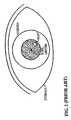
- FIG. 4is a diagram of the user's eye according to the preferred embodiment of the present invention.
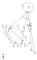
- FIG. 5is a diagram of the user's eye with regard to a camera located in a screen plane according to the preferred embodiment of the present invention.
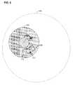
- FIG. 6is a diagram of the user's eye with regard to a camera located out of the screen plane according to the preferred embodiment of the present invention.
- FIG. 7is a flowchart of the eye gaze tracking method according to the preferred embodiment of the present invention.
- the user's eye 400includes the eyeball or sclera, a substantially spherical cornea 402 , and a pupil 404 having a pupil center 406 .
- non-spherical cornea modelsincluding parabolic models, are known in the art and can also be employed by the present invention.
- At least one camera(not shown) captures images of user's eye 400 , particularly cornea 402 .
- FIG. 4is such an image. Cameras may be head-mounted for easy acquisition of an eye image, but are preferably not head-mounted so the invention will be more widely accepted by users. The cameras track the user's head motion using known techniques.
- Each cameraincludes a focal center, an on-axis light source illuminating the eye, and an image plane defining an image coordinate system.
- the light sourceis preferably invisible to prevent user distraction, and may for example emit radiation in the near-infrared wavelength range.
- the images of user's eye 400include image aspects that will be used for determination of an eye gaze vector and determination of a point of regard, which is the intersection of the gaze vector and an observed object. These image aspects include a glint 408 due to light from the on-axis light source reflecting from eye 400 (either sclera or cornea 402 ) directly back to the camera.
- the image aspectsalso include a pupil image preferably created via retroreflection as is known in the art.
- Various image processing methods for identifying and locating the center of glint 408 , pupil 404 , and pupil center 406 in captured images of user's eye 400are known in the art.
- the image aspectsalso include a reflected version of a set of reference points 410 forming a test pattern 412 .
- Reference points 410define a reference coordinate system in real space. The relative positions of reference points 410 to each other are known, and reference points 410 are preferably co-planar, although that is not a limitation of the present invention.
- the reflection of reference points 410is spherically distorted by reflection from cornea 402 , which serves essentially as a convex spherical mirror.
- the reflected version of reference points 410is also distorted by perspective, as eye 400 is some distance from the camera and the reflected version goes through a perspective projection to the image plane. That is, test pattern 412 will be smaller in the image plane when eye 400 is farther away from reference points 410 .
- the reflectionalso varies in appearance due to the radius of cornea curvature, and the vertical and horizontal translation of user's eye 400 .
- Test pattern 412is preferably generated by a set of point light sources deployed around a display screen perimeter. If necessary, the light sources can be sequentially activated to enable easier identification of which light source corresponds to which image aspect. For example, a set of lights along one vertical edge of the display screen may be activated during acquisition of one image, then a set of lights along one horizontal edge of the display screen, and so forth. A variety of different lighting sequences and patterns can be used.
- the light sourcescan be built into a computer monitor during manufacture or subsequently attached to the screen, and preferably emit infrared light.
- test pattern 412may comprise an unobtrusively interlaced design depicted in a display screen; in this case no separate light sources are needed, but the camera is preferably synchronized to acquire an image of test pattern 412 reflection when the design is being displayed.
- a set of light sources on the display screen itselfcan also generate test pattern 412 ; for example, pixels in a liquid crystal display may include an infrared-emitting device such as a light-emitting diode. It is known in the art that red liquid crystal display cells are at least partially transparent to infrared light.
- Another method for defining test pattern 412is to deploy a high-contrast pre-printed pattern around the display screen perimeter; a checkerboard pattern for example.
- the regularly depicted display screen contentcan itself serve as test pattern 412 .
- the contentcan be fetched from video memory or a display adapter (not shown) to allow matching between the displayed content and image aspects. If a high frame rate camera is used, camera frames may be taken at a different frequency (e.g. twice the frequency) than the display screen refresh frequency, thus frames are captured in which the screen reflection changes over time. This allows easier separation of the screen reflection from the pupil image, e.g. by mere subtraction of consecutive frames.
- any distinctive pattern within the user's viewcan comprise test pattern 412 , even if not attached to the display screen or other object being viewed.
- test pattern 412is usually co-planar with the surface being viewed by the user, such as a computer monitor or display screen, but the present invention is not constrained as such.
- the reference coordinate systemmay not necessarily coincide with a coordinate system describing the target on which a point of regard exists, such as the x-y coordinates of a computer monitor. As long as a mapping between the reference coordinate system and the target coordinate system exists, the present invention can compute the point of regard.
- Other target objectscould include but are not limited to a desktop, a whiteboard, and a windshield.
- the camerais preferably positioned in the plane of reference points 410 , but the present invention is not limited to this embodiment, as will be described below.
- the present inventionmathematically maps the reference coordinate system to the image coordinate system by determining the specific spherical and perspective transformations that cause reference points 410 to appear at specific relative positions in the reflected version of test pattern 412 .
- the inventionupdates the mathematical mapping as needed to correct for changes in the position or orientation of user's eye 400 , but this updating is not necessarily required during every cycle of image capture and processing.
- the inventionthen applies the mathematical mapping to image aspects other than reflected reference points 410 , such as glint 408 and pupil center 406 , as will be described below.
- Camera 500includes a focal center 502 , an image plane 504 that defines an image coordinate system, and an on-axis light source (not shown).
- the center of user's eye 400is designated as point O.
- the reflection point of the on-axis light source from user's eye 400is designated as point G, which is seen by camera 500 as glint 408 as shown in FIG. 4 .
- the center of the pupilis designated as point P in real space, and is seen by camera 500 as pupil center 406 in image coordinates.
- Gaze vector 506is the line extending from point P to the specific location (point T) on an object being directly observed by a user.
- Point of regard 508is thus the intersection of gaze vector 506 with an observed object, and in this description the observed object is a display screen 510 as typically employed with a computer.
- Display screen 510is preferably modeled as plane S, which is screen plane 512 . While the observed object is preferably planar, the invention is not limited to gaze tracking on planar objects, as will be described further below.
- Point Vis the position of a virtual light source 514 that, if it actually existed at point V, its reflection from user's eye 400 would appear to coincide with pupil center 406 in image plane 504 of camera 500 .
- point Vis the location of the pupil center 406 when mapped from image coordinates to screen plane coordinates.
- Points F, P, G, O, T, and V as shown in FIG. 5are all co-planar. Points F, T, and V lie on a line that is co-planar with screen plane S. Angle FPT and angle VPT are equal; in other words, gaze vector 506 bisects angle FPV.
- the preferred embodiment of the inventionemploys at least one camera 500 co-planar with screen plane 512 to capture an image of reference points as reflected from cornea 402 .
- Specific reference pointsmay be identified by many different means, including alternate timing of light source energization as well as matching of specific reference point distribution patterns.
- the inventiondetermines the specific spherical and perspective transformations required to best map the reference points in real space to the test pattern they form in image space.
- the inventioncan for example optimize mapping variables (listed above) to minimize the difference between the observed test pattern in image coordinates and the results of transforming a known set of reference points in real space into an expected test pattern in image coordinates.
- the inventionapplies the mapping to observed image aspects, such as backlighted pupil images and the glint due to the on-axis light source.
- the inventioncan compute the location of point V in the coordinates of the observed object (screen plane 512 ) by locating pupil center 406 in image coordinates and then mathematically converting that location to coordinates within screen plane 512 .
- the inventioncan compute the location of glint 408 in image coordinates and determine a corresponding location in the coordinates of the observed object; in the case where camera 500 is co-planar with screen plane 512 , the mapped glint point is simply focal center 502 .
- Point of regard 508 on screen plane 512is typically the bisector of a line segment between point V and such a mapped glint point.
- Glint 408 and pupil center 406can be connected by a line in image coordinates and then reference point images that lie near the line can be selected for interpolation and mapping into the coordinates of the observed object.
- a single calibrated camera 500can determine point V and bisection of angle FPV determines gaze vector 506 ; if the eye-to-camera distance FP is known then the intersection of gaze vector 506 with screen plane 512 can be computed and determines point of regard 508 .
- the eye-to-camera distancecan be measured or estimated in many different ways, including the distance setting at which camera 500 yields a focused image, the scale of an object in image plane 504 as seen by a lens of known focal length, or via use of an infrared rangefinder.
- the present inventioncan also employ uncalibrated cameras 500 for gaze tracking, which is a significant advantage over existing gaze tracking systems.
- Each uncalibrated camera 500can determine a line on screen plane 512 containing point of regard 508 , and the intersection of two such lines determines point of regard 508 . Mere determination of a line that contains point of regard 508 is of use in many situations, as described in U.S. Ser. No. 09/844,682 cited previously.
- the intersection of the object with plane FPVis generally a curve instead of a line, and the method of computing gaze vector 506 by bisection of angle FPV will yield only approximate results. However, these results are still useful if the object being observed is not too strongly curved, or if the curvature is included in the mathematical mapping.
- An alternate embodiment of the present inventionemploys a laser pointer to create at least one reference point.
- the laser pointercan be scanned to produce a test pattern on objects in real space, so that reference points need not be placed on observed objects a priori.
- the laser pointercan be actively aimed, so that the laser pointer puts a spot at point V described above (i.e. a reflection of the laser spot is positioned at pupil center 406 in the image coordinate system).
- the lasermay emit infrared or visible light.
- Gaze vector 506can control a laser pointer such that a laser spot appears at point of regard 508 .
- the laser pointerfollows the motion of the point of regard so that user eye motion can be observed directly in real space.
- FIG. 6a diagram of user's eye 400 with regard to a camera 500 located out of the screen plane according to the preferred embodiment of the present invention is shown.
- focal center 502is no longer co-planar with screen plane 512
- the images of glint 408 and pupil center 406can be effectively projected back mathematically as points P′ and G′ on a line that is co-planar with screen plane 512 .
- Point Tis on the line connecting point G′ with point V, as previously described.
- step 700reference points 410 as described above are created or activated.
- step 702the invention acquires at least one image of cornea 402 including reflections of reference points 410 .
- step 704the invention defines a mathematical mapping between the image coordinate system and the reference coordinate system by determining the transformations (e.g. spherical and perspective) that cause reference points 410 as distributed in the image coordinate system to best fit their expected positions based on their known distribution in the reference coordinate system.
- the inventionmaps image aspects such as glint 408 and pupil center 406 from the image coordinate system to the reference coordinate system in step 706 .
- the inventioncomputes the point of regard from the mapped image aspects in step 708 , and returns to step 702 to repeat the eye gaze tracking method steps described.
- steps 702 and 704need not necessarily be performed during every single execution cycle of the method; it is within the scope of the invention that the mapping of coordinate systems by analysis of reflected reference points 410 may be performed only occasionally so the invention spends most of its time mapping image aspects other than reference points 410 and tracking the point of regard as described in steps 706 and 708 .
- a general purpose computeris programmed according to the inventive steps herein.
- the inventioncan also be embodied as an article of manufacture—a machine component—that is used by a digital processing apparatus to execute the present logic.
- This inventionis realized in a critical machine component that causes a digital processing apparatus to perform the inventive method steps herein.
- the inventionmay be embodied by a computer program that is executed by a processor within a computer as a series of computer-executable instructions. These instructions may reside, for example, in RAM of a computer or on a hard drive or optical drive of the computer, or the instructions may be stored on a DASD array, magnetic tape, electronic readonly memory, or other appropriate data storage device.
Landscapes
- Engineering & Computer Science (AREA)
- Health & Medical Sciences (AREA)
- Life Sciences & Earth Sciences (AREA)
- Human Computer Interaction (AREA)
- Physics & Mathematics (AREA)
- General Health & Medical Sciences (AREA)
- Ophthalmology & Optometry (AREA)
- Molecular Biology (AREA)
- Heart & Thoracic Surgery (AREA)
- Medical Informatics (AREA)
- Biomedical Technology (AREA)
- Surgery (AREA)
- Animal Behavior & Ethology (AREA)
- Biophysics (AREA)
- Public Health (AREA)
- Veterinary Medicine (AREA)
- General Physics & Mathematics (AREA)
- Multimedia (AREA)
- Theoretical Computer Science (AREA)
- Image Processing (AREA)
Abstract
Description
Claims (15)
Priority Applications (1)
| Application Number | Priority Date | Filing Date | Title |
|---|---|---|---|
| US10/034,524US6659611B2 (en) | 2001-12-28 | 2001-12-28 | System and method for eye gaze tracking using corneal image mapping |
Applications Claiming Priority (1)
| Application Number | Priority Date | Filing Date | Title |
|---|---|---|---|
| US10/034,524US6659611B2 (en) | 2001-12-28 | 2001-12-28 | System and method for eye gaze tracking using corneal image mapping |
Publications (2)
| Publication Number | Publication Date |
|---|---|
| US20030123027A1 US20030123027A1 (en) | 2003-07-03 |
| US6659611B2true US6659611B2 (en) | 2003-12-09 |
Family
ID=21876950
Family Applications (1)
| Application Number | Title | Priority Date | Filing Date |
|---|---|---|---|
| US10/034,524Expired - LifetimeUS6659611B2 (en) | 2001-12-28 | 2001-12-28 | System and method for eye gaze tracking using corneal image mapping |
Country Status (1)
| Country | Link |
|---|---|
| US (1) | US6659611B2 (en) |
Cited By (84)
| Publication number | Priority date | Publication date | Assignee | Title |
|---|---|---|---|---|
| US20020122014A1 (en)* | 2001-03-02 | 2002-09-05 | Rajasingham Arjuna Indraeswaran | Intelligent eye |
| US20040174496A1 (en)* | 2003-03-06 | 2004-09-09 | Qiang Ji | Calibration-free gaze tracking under natural head movement |
| US20040208394A1 (en)* | 2003-04-16 | 2004-10-21 | Sony Corporation | Image display device and method for preventing image Blurring |
| US20050099601A1 (en)* | 2003-11-07 | 2005-05-12 | Neuro Kinetics, Inc. | Portable video oculography system |
| WO2005046465A1 (en)* | 2003-11-14 | 2005-05-26 | Queen's University At Kingston | Method and apparatus for calibration-free eye tracking |
| US20050243054A1 (en)* | 2003-08-25 | 2005-11-03 | International Business Machines Corporation | System and method for selecting and activating a target object using a combination of eye gaze and key presses |
| US20050250579A1 (en)* | 2004-05-07 | 2005-11-10 | Valve Corporation | Generating eyes for a character in a virtual environment |
| US20060038881A1 (en)* | 2004-08-19 | 2006-02-23 | Microsoft Corporation | Stereoscopic image display |
| US20060110008A1 (en)* | 2003-11-14 | 2006-05-25 | Roel Vertegaal | Method and apparatus for calibration-free eye tracking |
| US20070011609A1 (en)* | 2005-07-07 | 2007-01-11 | Florida International University Board Of Trustees | Configurable, multimodal human-computer interface system and method |
| US20070171369A1 (en)* | 2006-01-16 | 2007-07-26 | Sensomotoric Instruments Gmbh | Method of determining the spatial relationship of an eye of a person with respect to a camera device |
| US20070291017A1 (en)* | 2006-06-19 | 2007-12-20 | Syeda-Mahmood Tanveer F | Camera-equipped writing tablet apparatus for digitizing form entries |
| US20090110245A1 (en)* | 2007-10-30 | 2009-04-30 | Karl Ola Thorn | System and method for rendering and selecting a discrete portion of a digital image for manipulation |
| US20090273562A1 (en)* | 2008-05-02 | 2009-11-05 | International Business Machines Corporation | Enhancing computer screen security using customized control of displayed content area |
| WO2010003410A1 (en)* | 2008-07-08 | 2010-01-14 | It-University Of Copenhagen | Eye gaze tracking |
| US20100094161A1 (en)* | 2008-10-09 | 2010-04-15 | Neuro Kinetics, Inc. | Quantitative, non-invasive, clinical diagnosis of traumatic brain injury using simulated distance visual stimulus device for neurologic testing |
| US20100092049A1 (en)* | 2008-04-08 | 2010-04-15 | Neuro Kinetics, Inc. | Method of Precision Eye-Tracking Through Use of Iris Edge Based Landmarks in Eye Geometry |
| US20100225743A1 (en)* | 2009-03-05 | 2010-09-09 | Microsoft Corporation | Three-Dimensional (3D) Imaging Based on MotionParallax |
| US20110202017A1 (en)* | 2010-02-12 | 2011-08-18 | Carl Zeiss Surgical Gmbh | Measurement system and method for establishing the refraction of an eye, the radius of curvature of the cornea or the internal pressure of an eye |
| US8020993B1 (en) | 2006-01-30 | 2011-09-20 | Fram Evan K | Viewing verification systems |
| US20110228975A1 (en)* | 2007-05-23 | 2011-09-22 | The University Of British Columbia | Methods and apparatus for estimating point-of-gaze in three dimensions |
| US8077914B1 (en)* | 2006-08-07 | 2011-12-13 | Arkady Kaplan | Optical tracking apparatus using six degrees of freedom |
| US20120230547A1 (en)* | 2009-11-27 | 2012-09-13 | Qinetiq Limited | Eye tracking |
| US20130002846A1 (en)* | 2010-03-22 | 2013-01-03 | Koninklijke Philips Electronics N.V. | System and method for tracking the point of gaze of an observer |
| US8487838B2 (en) | 2011-08-29 | 2013-07-16 | John R. Lewis | Gaze detection in a see-through, near-eye, mixed reality display |
| US20130258089A1 (en)* | 2011-11-03 | 2013-10-03 | Intel Corporation | Eye Gaze Based Image Capture |
| US20130278829A1 (en)* | 2012-04-21 | 2013-10-24 | General Electric Company | Method, system and computer readable medium for processing a medical video image |
| US20130329957A1 (en)* | 2010-12-08 | 2013-12-12 | Yoshinobu Ebisawa | Method for detecting point of gaze and device for detecting point of gaze |
| CN103530618A (en)* | 2013-10-23 | 2014-01-22 | 哈尔滨工业大学深圳研究生院 | Non-contact sight tracking method based on corneal reflex |
| US20140138544A1 (en)* | 2012-09-04 | 2014-05-22 | Innovega Inc. | Eye tracking system and related methods |
| US20140240675A1 (en)* | 2013-02-28 | 2014-08-28 | Carl Zeiss Meditec, Inc. | Systems and methods for improved ease and accuracy of gaze tracking |
| US8885882B1 (en) | 2011-07-14 | 2014-11-11 | The Research Foundation For The State University Of New York | Real time eye tracking for human computer interaction |
| US8885877B2 (en) | 2011-05-20 | 2014-11-11 | Eyefluence, Inc. | Systems and methods for identifying gaze tracking scene reference locations |
| US8911087B2 (en) | 2011-05-20 | 2014-12-16 | Eyefluence, Inc. | Systems and methods for measuring reactions of head, eyes, eyelids and pupils |
| US8929589B2 (en) | 2011-11-07 | 2015-01-06 | Eyefluence, Inc. | Systems and methods for high-resolution gaze tracking |
| US8955973B2 (en) | 2012-01-06 | 2015-02-17 | Google Inc. | Method and system for input detection using structured light projection |
| US8998414B2 (en) | 2011-09-26 | 2015-04-07 | Microsoft Technology Licensing, Llc | Integrated eye tracking and display system |
| US9039631B2 (en) | 2008-10-09 | 2015-05-26 | Neuro Kinetics | Quantitative, non-invasive, clinical diagnosis of traumatic brain injury using VOG device for neurologic testing |
| CN104661579A (en)* | 2012-07-25 | 2015-05-27 | 达瓦洛尔战略咨询和技术有限公司 | Apparatus for measuring the topography and thickness of the cornea and measuring method used |
| WO2014192001A3 (en)* | 2013-05-30 | 2015-06-04 | Umoove Services Ltd. | Smooth pursuit gaze tracking |
| US9202443B2 (en) | 2011-08-30 | 2015-12-01 | Microsoft Technology Licensing, Llc | Improving display performance with iris scan profiling |
| US9213405B2 (en) | 2010-12-16 | 2015-12-15 | Microsoft Technology Licensing, Llc | Comprehension and intent-based content for augmented reality displays |
| US20160034029A1 (en)* | 2011-12-14 | 2016-02-04 | Kenton M. Lyons | Gaze activated content transfer system |
| US9262680B2 (en) | 2012-07-31 | 2016-02-16 | Japan Science And Technology Agency | Point-of-gaze detection device, point-of-gaze detecting method, personal parameter calculating device, personal parameter calculating method, program, and computer-readable storage medium |
| US9265458B2 (en) | 2012-12-04 | 2016-02-23 | Sync-Think, Inc. | Application of smooth pursuit cognitive testing paradigms to clinical drug development |
| US9268024B1 (en) | 2012-01-06 | 2016-02-23 | Google Inc. | Expectation maximization to determine position of ambient glints |
| US9292765B2 (en) | 2014-01-07 | 2016-03-22 | Microsoft Technology Licensing, Llc | Mapping glints to light sources |
| US9323325B2 (en) | 2011-08-30 | 2016-04-26 | Microsoft Technology Licensing, Llc | Enhancing an object of interest in a see-through, mixed reality display device |
| US9380976B2 (en) | 2013-03-11 | 2016-07-05 | Sync-Think, Inc. | Optical neuroinformatics |
| US9632180B2 (en) | 2009-04-01 | 2017-04-25 | Tobii Ab | Visual display with illuminators for gaze tracking |
| US9727136B2 (en)* | 2014-05-19 | 2017-08-08 | Microsoft Technology Licensing, Llc | Gaze detection calibration |
| US9740938B2 (en) | 2015-04-28 | 2017-08-22 | Microsoft Technology Licensing, Llc | Eye gaze correction |
| US9749581B2 (en) | 2015-04-28 | 2017-08-29 | Microsoft Technology Licensing, Llc | Eye gaze correction |
| US9898082B1 (en) | 2016-11-01 | 2018-02-20 | Massachusetts Institute Of Technology | Methods and apparatus for eye tracking |
| US10016130B2 (en) | 2015-09-04 | 2018-07-10 | University Of Massachusetts | Eye tracker system and methods for detecting eye parameters |
| US10039445B1 (en) | 2004-04-01 | 2018-08-07 | Google Llc | Biosensors, communicators, and controllers monitoring eye movement and methods for using them |
| US10212414B2 (en) | 2016-08-01 | 2019-02-19 | Microsoft Technology Licensing, Llc | Dynamic realignment of stereoscopic digital consent |
| US10223832B2 (en) | 2011-08-17 | 2019-03-05 | Microsoft Technology Licensing, Llc | Providing location occupancy analysis via a mixed reality device |
| US10234940B2 (en) | 2015-02-04 | 2019-03-19 | Itu Business Development A/S | Gaze tracker and a gaze tracking method |
| US10398309B2 (en) | 2008-10-09 | 2019-09-03 | Neuro Kinetics, Inc. | Noninvasive rapid screening of mild traumatic brain injury using combination of subject's objective oculomotor, vestibular and reaction time analytic variables |
| US10437330B2 (en)* | 2017-09-25 | 2019-10-08 | Compal Electronics, Inc. | Gaze detection, identification and control method |
| US10485420B2 (en) | 2017-02-17 | 2019-11-26 | Analog Devices Global Unlimited Company | Eye gaze tracking |
| CN111339982A (en)* | 2020-03-05 | 2020-06-26 | 西北工业大学 | A feature-based method for realizing multi-level pupil center positioning technology |
| US10743808B2 (en) | 2012-08-06 | 2020-08-18 | Neuro Kinetics | Method and associated apparatus for detecting minor traumatic brain injury |
| US10761329B2 (en)* | 2016-01-05 | 2020-09-01 | Qd Laser, Inc. | Image projection device |
| US10768696B2 (en) | 2017-10-05 | 2020-09-08 | Microsoft Technology Licensing, Llc | Eye gaze correction using pursuit vector |
| US10902628B1 (en)* | 2018-06-22 | 2021-01-26 | Mirametrix Inc. | Method for estimating user eye orientation using a system-independent learned mapping |
| US20210132690A1 (en)* | 2019-11-05 | 2021-05-06 | Micron Technology, Inc. | Rendering enhancement based in part on eye tracking |
| US11127210B2 (en) | 2011-08-24 | 2021-09-21 | Microsoft Technology Licensing, Llc | Touch and social cues as inputs into a computer |
| US11386290B2 (en)* | 2019-03-29 | 2022-07-12 | Tobii Ab | Training an eye tracking model |
| US11503998B1 (en) | 2021-05-05 | 2022-11-22 | Innodem Neurosciences | Method and a system for detection of eye gaze-pattern abnormalities and related neurological diseases |
| US11750794B2 (en) | 2015-03-24 | 2023-09-05 | Augmedics Ltd. | Combining video-based and optic-based augmented reality in a near eye display |
| US11801115B2 (en) | 2019-12-22 | 2023-10-31 | Augmedics Ltd. | Mirroring in image guided surgery |
| US11896445B2 (en) | 2021-07-07 | 2024-02-13 | Augmedics Ltd. | Iliac pin and adapter |
| US11974887B2 (en) | 2018-05-02 | 2024-05-07 | Augmedics Ltd. | Registration marker for an augmented reality system |
| US11980429B2 (en) | 2018-11-26 | 2024-05-14 | Augmedics Ltd. | Tracking methods for image-guided surgery |
| US11980506B2 (en) | 2019-07-29 | 2024-05-14 | Augmedics Ltd. | Fiducial marker |
| US12044856B2 (en) | 2022-09-13 | 2024-07-23 | Augmedics Ltd. | Configurable augmented reality eyewear for image-guided medical intervention |
| US12150821B2 (en) | 2021-07-29 | 2024-11-26 | Augmedics Ltd. | Rotating marker and adapter for image-guided surgery |
| US12178666B2 (en) | 2019-07-29 | 2024-12-31 | Augmedics Ltd. | Fiducial marker |
| US12186028B2 (en) | 2020-06-15 | 2025-01-07 | Augmedics Ltd. | Rotating marker for image guided surgery |
| US12239385B2 (en) | 2020-09-09 | 2025-03-04 | Augmedics Ltd. | Universal tool adapter |
| US12354227B2 (en) | 2022-04-21 | 2025-07-08 | Augmedics Ltd. | Systems for medical image visualization |
| US12417595B2 (en) | 2021-08-18 | 2025-09-16 | Augmedics Ltd. | Augmented-reality surgical system using depth sensing |
Families Citing this family (66)
| Publication number | Priority date | Publication date | Assignee | Title |
|---|---|---|---|---|
| EP1569402A1 (en)* | 2004-02-26 | 2005-08-31 | Alcatel | Digital subscriber line modem with bitloading using channel condition model |
| GB2412431B (en)* | 2004-03-25 | 2007-11-07 | Hewlett Packard Development Co | Self-calibration for an eye tracker |
| WO2005099639A1 (en)* | 2004-04-09 | 2005-10-27 | Steinert Roger F | Laser system for vision correction |
| US8317327B2 (en)* | 2005-03-16 | 2012-11-27 | Lc Technologies, Inc. | System and method for eyeball surface topography as a biometric discriminator |
| US20070265507A1 (en)* | 2006-03-13 | 2007-11-15 | Imotions Emotion Technology Aps | Visual attention and emotional response detection and display system |
| JP4876687B2 (en)* | 2006-04-19 | 2012-02-15 | 株式会社日立製作所 | Attention level measuring device and attention level measuring system |
| TWI319680B (en)* | 2006-08-30 | 2010-01-11 | Face-detection-based remote-control system and method and face-detection-based remote-controllable multimedia system | |
| JP2008136789A (en)* | 2006-12-05 | 2008-06-19 | Nec Corp | Eyeball parameter estimation apparatus and method |
| KR100850357B1 (en)* | 2006-12-06 | 2008-08-04 | 한국전자통신연구원 | System and method for tracking gaze |
| US20100010370A1 (en) | 2008-07-09 | 2010-01-14 | De Lemos Jakob | System and method for calibrating and normalizing eye data in emotional testing |
| US8136944B2 (en) | 2008-08-15 | 2012-03-20 | iMotions - Eye Tracking A/S | System and method for identifying the existence and position of text in visual media content and for determining a subjects interactions with the text |
| WO2010100567A2 (en) | 2009-03-06 | 2010-09-10 | Imotions- Emotion Technology A/S | System and method for determining emotional response to olfactory stimuli |
| US8860729B2 (en)* | 2009-07-22 | 2014-10-14 | Imagemovers Digital Llc | Gaze intent estimation for retargeting of characters |
| IT1399174B1 (en)* | 2009-09-28 | 2013-04-11 | Corsoni | VISUAL DEFECT DETECTION SYSTEM |
| EP2309307B1 (en)* | 2009-10-08 | 2020-12-09 | Tobii Technology AB | Eye tracking using a GPU |
| US9302092B2 (en)* | 2009-12-30 | 2016-04-05 | Cardiac Pacemakers, Inc. | Multi-function lead implant tool |
| WO2011156195A2 (en)* | 2010-06-09 | 2011-12-15 | Dynavox Systems Llc | Speech generation device with a head mounted display unit |
| US9083129B2 (en) | 2010-07-14 | 2015-07-14 | Cardiac Pacemakers, Inc. | Multipolar lead evaluation device |
| ITMI20101461A1 (en)* | 2010-08-03 | 2012-02-04 | Int Op Internat Operator Sa | METHOD AND EQUIPMENT FOR THE CHOICE OF LENSES FOR THE CORRECTION OF PRESBIOPIES |
| US9760123B2 (en)* | 2010-08-06 | 2017-09-12 | Dynavox Systems Llc | Speech generation device with a projected display and optical inputs |
| DE102010040694A1 (en)* | 2010-09-14 | 2012-03-15 | Robert Bosch Gmbh | Head-Up Display |
| US9405364B2 (en)* | 2010-10-29 | 2016-08-02 | IT-Universitetet i København | Method of determining reflections of light |
| US8670183B2 (en) | 2011-03-07 | 2014-03-11 | Microsoft Corporation | Augmented view of advertisements |
| EP2583619B1 (en)* | 2011-10-22 | 2022-03-16 | Alcon Inc. | Apparatus for monitoring one or more surgical parameters of the eye |
| JP2014064784A (en)* | 2012-09-26 | 2014-04-17 | Renesas Microsystem:Kk | Visual line detection device, visual line detection method and program |
| CN102981616B (en)* | 2012-11-06 | 2017-09-22 | 中兴通讯股份有限公司 | The recognition methods of object and system and computer in augmented reality |
| CN103076876B (en)* | 2012-11-22 | 2016-02-10 | 西安电子科技大学 | Based on character entry apparatus and the method for eye tracking and speech recognition |
| US9612656B2 (en) | 2012-11-27 | 2017-04-04 | Facebook, Inc. | Systems and methods of eye tracking control on mobile device |
| US10884577B2 (en)* | 2013-01-15 | 2021-01-05 | Poow Innovation Ltd. | Identification of dynamic icons based on eye movement |
| US10515377B1 (en)* | 2013-03-14 | 2019-12-24 | Verily Life Sciences Llc | User studies using interactive devices |
| JP6210023B2 (en)* | 2013-11-28 | 2017-10-11 | 株式会社Jvcケンウッド | Gaze detection support apparatus and gaze detection support method |
| DE102014206569A1 (en) | 2014-04-04 | 2015-10-08 | Robert Bosch Gmbh | A method and apparatus for controlling a light output of an imager of a visual field display device for displaying a stereoscopic image and visual field display device |
| CN103927014A (en)* | 2014-04-21 | 2014-07-16 | 广州杰赛科技股份有限公司 | Character input method and device |
| EP3137968B1 (en) | 2014-04-29 | 2019-10-16 | Hewlett-Packard Development Company, L.P. | Gaze detector using reference frames in media |
| BR112016028995B1 (en)* | 2014-06-12 | 2023-02-14 | Sr Labs S.R.L. | CALIBRATION METHOD FOR AN EYE TRACKER, CALIBRATION DEVICE FOR AN EYE TRACKER, EYE TRACKER EQUIPMENT, METHOD OF OPERATION OF AN EYE TRACKER EQUIPMENT AND COMPUTER READABLE MEDIA |
| US9798383B2 (en)* | 2014-09-19 | 2017-10-24 | Intel Corporation | Facilitating dynamic eye torsion-based eye tracking on computing devices |
| JP6547268B2 (en)* | 2014-10-02 | 2019-07-24 | 富士通株式会社 | Eye position detection device, eye position detection method and eye position detection program |
| JP6201956B2 (en)* | 2014-10-24 | 2017-09-27 | 株式会社Jvcケンウッド | Gaze detection device and gaze detection method |
| US10354136B2 (en) | 2015-03-03 | 2019-07-16 | Apple Inc. | Head mounted eye tracking device and method for providing drift free eye tracking through a lens system |
| US9983709B2 (en)* | 2015-11-02 | 2018-05-29 | Oculus Vr, Llc | Eye tracking using structured light |
| KR101825450B1 (en)* | 2016-04-01 | 2018-02-05 | 엘지전자 주식회사 | Vehicle control apparatus and method thereof |
| CN106168853B (en)* | 2016-06-23 | 2019-10-01 | 中国科学技术大学 | A kind of free space wear-type gaze tracking system |
| US9874934B1 (en)* | 2016-07-29 | 2018-01-23 | International Business Machines Corporation | System, method, and recording medium for tracking gaze with respect to a moving plane with a camera with respect to the moving plane |
| US10137893B2 (en)* | 2016-09-26 | 2018-11-27 | Keith J. Hanna | Combining driver alertness with advanced driver assistance systems (ADAS) |
| US10022045B1 (en)* | 2017-02-28 | 2018-07-17 | David Evans | Method and apparatus for vision acuity testing |
| JP6800091B2 (en)* | 2017-06-09 | 2020-12-16 | 株式会社豊田中央研究所 | Line-of-sight measuring device and program |
| EP3453317B1 (en)* | 2017-09-08 | 2021-07-14 | Tobii AB | Pupil radius compensation |
| US10867252B2 (en) | 2017-09-08 | 2020-12-15 | Tobii Ab | Continuous calibration based on pupil characteristics |
| EP3486834B1 (en)* | 2017-11-16 | 2025-09-24 | Smart Eye AB | Detection of a pose of an eye |
| US10747310B1 (en)* | 2018-06-19 | 2020-08-18 | Facebook Technologies, Llc | Time of flight based eye tracker |
| SE542887C2 (en)* | 2018-10-31 | 2020-08-11 | Tobii Ab | Gaze tracking using mapping of pupil center position |
| SE1851597A1 (en)* | 2018-12-17 | 2020-06-02 | Tobii Ab | Gaze tracking via tracing of light paths |
| CN111513670B (en)* | 2018-12-21 | 2023-10-10 | 托比股份公司 | Estimation of corneal radius for use in eye tracking |
| JP7283841B2 (en)* | 2019-03-28 | 2023-05-30 | 株式会社豊田中央研究所 | Gaze measurement device |
| WO2021056177A1 (en) | 2019-09-24 | 2021-04-01 | Citrix Systems, Inc. | Systems and methods for screen brightness control and auto-lock based on eye detection |
| CN112578903B (en)* | 2019-09-30 | 2024-09-27 | 托比股份公司 | Eye movement tracking method and eye movement tracker |
| CN112651270B (en)* | 2019-10-12 | 2024-08-02 | 北京七鑫易维信息技术有限公司 | Gaze information determining method and device, terminal equipment and display object |
| CN111443804B (en)* | 2019-12-27 | 2022-08-19 | 安徽大学 | Method and system for describing fixation point track based on video analysis |
| CN113723155B (en)* | 2020-10-14 | 2024-09-20 | 天翼数字生活科技有限公司 | Method and system for measuring user visual experience |
| CN114967904A (en)* | 2021-02-19 | 2022-08-30 | 北京京东方光电科技有限公司 | Sight line positioning method, head-mounted display device, computer device and storage medium |
| CN112966872A (en)* | 2021-03-17 | 2021-06-15 | 京诚数字科技(江苏)有限公司 | Camera-based attention prediction analysis method and device and terminal |
| CN113592959B (en)* | 2021-08-17 | 2023-11-28 | 北京博视智动技术有限公司 | Visual processing-based membrane lamination method and system |
| CN115089300B (en)* | 2022-06-14 | 2025-09-02 | 上海微创医疗机器人(集团)股份有限公司 | Control method and surgical robot based on eye positioning and voice recognition |
| SE546205C2 (en)* | 2022-06-21 | 2024-07-02 | Tobii Ab | Method and system for determining a current gaze direction |
| CN117475501B (en)* | 2023-11-06 | 2025-10-03 | 中国科学院深圳先进技术研究院 | Method, device and equipment for processing target object's sight line information |
| CN118314204A (en)* | 2024-03-14 | 2024-07-09 | 珠海莫界科技有限公司 | Light source position calibration method, device and storage medium |
Citations (13)
| Publication number | Priority date | Publication date | Assignee | Title |
|---|---|---|---|---|
| US4597648A (en) | 1983-04-01 | 1986-07-01 | Keratometer Research And Development | Keratometer |
| US4836670A (en)* | 1987-08-19 | 1989-06-06 | Center For Innovative Technology | Eye movement detector |
| US5231674A (en) | 1989-06-09 | 1993-07-27 | Lc Technologies, Inc. | Eye tracking method and apparatus |
| US5270748A (en)* | 1992-01-30 | 1993-12-14 | Mak Technologies, Inc. | High-speed eye tracking device and method |
| US5325133A (en) | 1991-10-07 | 1994-06-28 | Konami Co., Ltd. | Device for measuring a retina reflected light amount and a gaze detecting apparatus using the same |
| US5331149A (en) | 1990-12-31 | 1994-07-19 | Kopin Corporation | Eye tracking system having an array of photodetectors aligned respectively with an array of pixels |
| EP0631222A1 (en) | 1993-06-21 | 1994-12-28 | International Business Machines Corporation | Gazing point estimation device |
| US5481622A (en)* | 1994-03-01 | 1996-01-02 | Rensselaer Polytechnic Institute | Eye tracking apparatus and method employing grayscale threshold values |
| US5644642A (en) | 1995-04-03 | 1997-07-01 | Carl Zeiss, Inc. | Gaze tracking using optical coherence tomography |
| WO1999026126A1 (en) | 1997-11-17 | 1999-05-27 | British Telecommunications Public Limited Company | User interface |
| US6061084A (en) | 1998-01-21 | 2000-05-09 | New York University | Displayer and a method for displaying |
| US6152563A (en)* | 1998-02-20 | 2000-11-28 | Hutchinson; Thomas E. | Eye gaze direction tracker |
| US6204828B1 (en) | 1998-03-31 | 2001-03-20 | International Business Machines Corporation | Integrated gaze/manual cursor positioning system |
- 2001
- 2001-12-28USUS10/034,524patent/US6659611B2/ennot_activeExpired - Lifetime
Patent Citations (13)
| Publication number | Priority date | Publication date | Assignee | Title |
|---|---|---|---|---|
| US4597648A (en) | 1983-04-01 | 1986-07-01 | Keratometer Research And Development | Keratometer |
| US4836670A (en)* | 1987-08-19 | 1989-06-06 | Center For Innovative Technology | Eye movement detector |
| US5231674A (en) | 1989-06-09 | 1993-07-27 | Lc Technologies, Inc. | Eye tracking method and apparatus |
| US5331149A (en) | 1990-12-31 | 1994-07-19 | Kopin Corporation | Eye tracking system having an array of photodetectors aligned respectively with an array of pixels |
| US5325133A (en) | 1991-10-07 | 1994-06-28 | Konami Co., Ltd. | Device for measuring a retina reflected light amount and a gaze detecting apparatus using the same |
| US5270748A (en)* | 1992-01-30 | 1993-12-14 | Mak Technologies, Inc. | High-speed eye tracking device and method |
| EP0631222A1 (en) | 1993-06-21 | 1994-12-28 | International Business Machines Corporation | Gazing point estimation device |
| US5481622A (en)* | 1994-03-01 | 1996-01-02 | Rensselaer Polytechnic Institute | Eye tracking apparatus and method employing grayscale threshold values |
| US5644642A (en) | 1995-04-03 | 1997-07-01 | Carl Zeiss, Inc. | Gaze tracking using optical coherence tomography |
| WO1999026126A1 (en) | 1997-11-17 | 1999-05-27 | British Telecommunications Public Limited Company | User interface |
| US6061084A (en) | 1998-01-21 | 2000-05-09 | New York University | Displayer and a method for displaying |
| US6152563A (en)* | 1998-02-20 | 2000-11-28 | Hutchinson; Thomas E. | Eye gaze direction tracker |
| US6204828B1 (en) | 1998-03-31 | 2001-03-20 | International Business Machines Corporation | Integrated gaze/manual cursor positioning system |
Non-Patent Citations (8)
| Title |
|---|
| Arnon Amir et al., "Calibration-Free Eye Gaze Tracking", U.S. Ser. No. 09/844,682. |
| Eye Movement Equipment Database (EMED), University of Darby, http://ibs.derby.ac.uk/emed. |
| J. Liu et al., "Three-dimensional PC: toward novel forms of human-computer interaction", in Three-Dimensional Video and Display: Devices and Systems SPIE CR76, Nov. 5-8, 2000, Boston, MA, USA. |
| K. Talmi and J. Liu, "Eye and Gaze Tracking for Visually Controlled Interactive Stereoscopic Displays", Image Communication, vol. 14, No. 10, p. 799-810, 1999. |
| P. J. Kennedy, "Point of Regard Tracking Device", IBM Technical Disclosure Bulletin vol. 34, No. 10A, Mar. 1992. |
| S. Shih, Y. Wu, J. Liu, "A Calibration-Free Gaze Tracking Technique", ICPR 2000, vol. 4, pp. 201-204, 2000. |
| Z. Zhang, "A Flexible New Technique for Camera Calibration", IEEE Transactions on Pattern Analysis and Machine Intelligence, vol. 22, No. 11, p1330-1334, 2000, also available as Technical Report MSR-TR-98-71, Microsoft Research, Microsoft Corporation, Redmond WA, http://research.microsoft.com/˜zhang/Papers/TR98-71.pdf. |
| Z. Zhang, "A Flexible New Technique for Camera Calibration", IEEE Transactions on Pattern Analysis and Machine Intelligence, vol. 22, No. 11, p1330-1334, 2000, also available as Technical Report MSR-TR-98-71, Microsoft Research, Microsoft Corporation, Redmond WA, http://research.microsoft.com/<~>zhang/Papers/TR98-71.pdf. |
Cited By (152)
| Publication number | Priority date | Publication date | Assignee | Title |
|---|---|---|---|---|
| US7091928B2 (en)* | 2001-03-02 | 2006-08-15 | Rajasingham Arjuna Indraeswara | Intelligent eye |
| US20020122014A1 (en)* | 2001-03-02 | 2002-09-05 | Rajasingham Arjuna Indraeswaran | Intelligent eye |
| US20040174496A1 (en)* | 2003-03-06 | 2004-09-09 | Qiang Ji | Calibration-free gaze tracking under natural head movement |
| US7306337B2 (en) | 2003-03-06 | 2007-12-11 | Rensselaer Polytechnic Institute | Calibration-free gaze tracking under natural head movement |
| US20040208394A1 (en)* | 2003-04-16 | 2004-10-21 | Sony Corporation | Image display device and method for preventing image Blurring |
| US9274598B2 (en) | 2003-08-25 | 2016-03-01 | International Business Machines Corporation | System and method for selecting and activating a target object using a combination of eye gaze and key presses |
| US20050243054A1 (en)* | 2003-08-25 | 2005-11-03 | International Business Machines Corporation | System and method for selecting and activating a target object using a combination of eye gaze and key presses |
| US7520614B2 (en) | 2003-11-07 | 2009-04-21 | Neuro Kinetics, Inc | Portable video oculography with region of interest image processing |
| US7866818B2 (en) | 2003-11-07 | 2011-01-11 | Neuro Kinetics, Inc | Portable modular video oculography system and video occulography system with head position sensor and video occulography system with animated eye display |
| US7731360B2 (en) | 2003-11-07 | 2010-06-08 | Neuro Kinetics | Portable video oculography system |
| US9101296B2 (en) | 2003-11-07 | 2015-08-11 | Neuro Kinetics | Integrated video and electro-oculography system |
| US7665845B2 (en) | 2003-11-07 | 2010-02-23 | Neuro Kinetics | Portable high speed head mounted pupil dilation tracking system |
| US20050099601A1 (en)* | 2003-11-07 | 2005-05-12 | Neuro Kinetics, Inc. | Portable video oculography system |
| US20070121068A1 (en)* | 2003-11-07 | 2007-05-31 | Neuro Kinetics, Inc. | Portable video oculography system with integral light stimulus system |
| US20070132841A1 (en)* | 2003-11-07 | 2007-06-14 | Neuro Kinetics, Inc. | Portable video oculography system with integral calibration light |
| US7753523B2 (en) | 2003-11-07 | 2010-07-13 | Neuro Kinetics | Portable video oculography system with integral calibration light |
| US20080278685A1 (en)* | 2003-11-07 | 2008-11-13 | Neuro Kinetics, Inc. | Portable modular video oculography system and video occulography system with head position sensor and video occulography system with animated eye display |
| US7448751B2 (en) | 2003-11-07 | 2008-11-11 | Neuro Kinetics, Inc. | Portable video oculography system with integral light stimulus system |
| US20080049187A1 (en)* | 2003-11-07 | 2008-02-28 | Neuro Kinetics, Inc. | Portable video oculography with region of interest image processing |
| US20080049186A1 (en)* | 2003-11-07 | 2008-02-28 | Neuro Kinetics, Inc. | Portable high speed head mounted pupil dilation tracking system |
| US20080273084A1 (en)* | 2003-11-07 | 2008-11-06 | Neuro Kinetics, Inc. | Integrated video and electro-oculography system |
| WO2005046465A1 (en)* | 2003-11-14 | 2005-05-26 | Queen's University At Kingston | Method and apparatus for calibration-free eye tracking |
| US20050175218A1 (en)* | 2003-11-14 | 2005-08-11 | Roel Vertegaal | Method and apparatus for calibration-free eye tracking using multiple glints or surface reflections |
| US7963652B2 (en) | 2003-11-14 | 2011-06-21 | Queen's University At Kingston | Method and apparatus for calibration-free eye tracking |
| US7809160B2 (en)* | 2003-11-14 | 2010-10-05 | Queen's University At Kingston | Method and apparatus for calibration-free eye tracking using multiple glints or surface reflections |
| US20060110008A1 (en)* | 2003-11-14 | 2006-05-25 | Roel Vertegaal | Method and apparatus for calibration-free eye tracking |
| US10039445B1 (en) | 2004-04-01 | 2018-08-07 | Google Llc | Biosensors, communicators, and controllers monitoring eye movement and methods for using them |
| US7388580B2 (en)* | 2004-05-07 | 2008-06-17 | Valve Corporation | Generating eyes for a character in a virtual environment |
| US20050250579A1 (en)* | 2004-05-07 | 2005-11-10 | Valve Corporation | Generating eyes for a character in a virtual environment |
| US7705876B2 (en) | 2004-08-19 | 2010-04-27 | Microsoft Corporation | Stereoscopic image display |
| US20060038881A1 (en)* | 2004-08-19 | 2006-02-23 | Microsoft Corporation | Stereoscopic image display |
| US9030532B2 (en) | 2004-08-19 | 2015-05-12 | Microsoft Technology Licensing, Llc | Stereoscopic image display |
| US20060038880A1 (en)* | 2004-08-19 | 2006-02-23 | Microsoft Corporation | Stereoscopic image display |
| US20070011609A1 (en)* | 2005-07-07 | 2007-01-11 | Florida International University Board Of Trustees | Configurable, multimodal human-computer interface system and method |
| US20070171369A1 (en)* | 2006-01-16 | 2007-07-26 | Sensomotoric Instruments Gmbh | Method of determining the spatial relationship of an eye of a person with respect to a camera device |
| US7600873B2 (en)* | 2006-01-16 | 2009-10-13 | Sensomotoric Instruments Gmbh | Method of determining the spatial relationship of an eye of a person with respect to a camera device |
| US8020993B1 (en) | 2006-01-30 | 2011-09-20 | Fram Evan K | Viewing verification systems |
| US8696121B1 (en) | 2006-01-30 | 2014-04-15 | Evan K. Fram | Viewing verification systems |
| US7633493B2 (en) | 2006-06-19 | 2009-12-15 | International Business Machines Corporation | Camera-equipped writing tablet apparatus for digitizing form entries |
| US20070291017A1 (en)* | 2006-06-19 | 2007-12-20 | Syeda-Mahmood Tanveer F | Camera-equipped writing tablet apparatus for digitizing form entries |
| US8077914B1 (en)* | 2006-08-07 | 2011-12-13 | Arkady Kaplan | Optical tracking apparatus using six degrees of freedom |
| US20110228975A1 (en)* | 2007-05-23 | 2011-09-22 | The University Of British Columbia | Methods and apparatus for estimating point-of-gaze in three dimensions |
| US8457352B2 (en) | 2007-05-23 | 2013-06-04 | The University Of British Columbia | Methods and apparatus for estimating point-of-gaze in three dimensions |
| US9070017B2 (en) | 2007-05-23 | 2015-06-30 | Mirametrix Inc. | Methods and apparatus for estimating point-of-gaze in three dimensions |
| US20090110245A1 (en)* | 2007-10-30 | 2009-04-30 | Karl Ola Thorn | System and method for rendering and selecting a discrete portion of a digital image for manipulation |
| US9655515B2 (en) | 2008-04-08 | 2017-05-23 | Neuro Kinetics | Method of precision eye-tracking through use of iris edge based landmarks in eye geometry |
| US20100092049A1 (en)* | 2008-04-08 | 2010-04-15 | Neuro Kinetics, Inc. | Method of Precision Eye-Tracking Through Use of Iris Edge Based Landmarks in Eye Geometry |
| US20090273562A1 (en)* | 2008-05-02 | 2009-11-05 | International Business Machines Corporation | Enhancing computer screen security using customized control of displayed content area |
| US20110182472A1 (en)* | 2008-07-08 | 2011-07-28 | Dan Witzner Hansen | Eye gaze tracking |
| US9398848B2 (en)* | 2008-07-08 | 2016-07-26 | It-University Of Copenhagen | Eye gaze tracking |
| WO2010003410A1 (en)* | 2008-07-08 | 2010-01-14 | It-University Of Copenhagen | Eye gaze tracking |
| US9039632B2 (en) | 2008-10-09 | 2015-05-26 | Neuro Kinetics, Inc | Quantitative, non-invasive, clinical diagnosis of traumatic brain injury using VOG device for neurologic optokinetic testing |
| US10398309B2 (en) | 2008-10-09 | 2019-09-03 | Neuro Kinetics, Inc. | Noninvasive rapid screening of mild traumatic brain injury using combination of subject's objective oculomotor, vestibular and reaction time analytic variables |
| US9039631B2 (en) | 2008-10-09 | 2015-05-26 | Neuro Kinetics | Quantitative, non-invasive, clinical diagnosis of traumatic brain injury using VOG device for neurologic testing |
| US20100094161A1 (en)* | 2008-10-09 | 2010-04-15 | Neuro Kinetics, Inc. | Quantitative, non-invasive, clinical diagnosis of traumatic brain injury using simulated distance visual stimulus device for neurologic testing |
| US8585609B2 (en) | 2008-10-09 | 2013-11-19 | Neuro Kinetics, Inc. | Quantitative, non-invasive, clinical diagnosis of traumatic brain injury using simulated distance visual stimulus device for neurologic testing |
| US20100225743A1 (en)* | 2009-03-05 | 2010-09-09 | Microsoft Corporation | Three-Dimensional (3D) Imaging Based on MotionParallax |
| US8743187B2 (en) | 2009-03-05 | 2014-06-03 | Microsoft Corporation | Three-dimensional (3D) imaging based on MotionParallax |
| US8199186B2 (en) | 2009-03-05 | 2012-06-12 | Microsoft Corporation | Three-dimensional (3D) imaging based on motionparallax |
| US10191542B2 (en) | 2009-04-01 | 2019-01-29 | Tobii Ab | Visual display with illuminators for gaze tracking |
| US9632180B2 (en) | 2009-04-01 | 2017-04-25 | Tobii Ab | Visual display with illuminators for gaze tracking |
| US20120230547A1 (en)* | 2009-11-27 | 2012-09-13 | Qinetiq Limited | Eye tracking |
| US8908917B2 (en)* | 2009-11-27 | 2014-12-09 | Qinetiq Limited | Eye tracking apparatus including indication of eye direction |
| US10080493B2 (en) | 2010-02-12 | 2018-09-25 | Carl Zeiss Meditec Ag | Measurement system and method for establishing the refraction of an eye, the radius of curvature of the cornea or the internal pressure of an eye |
| US20110202017A1 (en)* | 2010-02-12 | 2011-08-18 | Carl Zeiss Surgical Gmbh | Measurement system and method for establishing the refraction of an eye, the radius of curvature of the cornea or the internal pressure of an eye |
| US11039744B2 (en) | 2010-02-12 | 2021-06-22 | Carl Zeiss Meditec Ag | Measurement system and method for establishing the refraction of an eye, the radius of curvature of the cornea or the internal pressure of an eye |
| US11039743B2 (en) | 2010-02-12 | 2021-06-22 | Carl Zeiss Meditec Ag | Measurement system and method for establishing the refraction of an eye, the radius of curvature of the cornea or the internal pressure of an eye |
| US9237844B2 (en)* | 2010-03-22 | 2016-01-19 | Koninklijke Philips N.V. | System and method for tracking the point of gaze of an observer |
| US20130002846A1 (en)* | 2010-03-22 | 2013-01-03 | Koninklijke Philips Electronics N.V. | System and method for tracking the point of gaze of an observer |
| US9329683B2 (en)* | 2010-12-08 | 2016-05-03 | National University Corporation Shizuoka University | Method for detecting point of gaze and device for detecting point of gaze |
| US20130329957A1 (en)* | 2010-12-08 | 2013-12-12 | Yoshinobu Ebisawa | Method for detecting point of gaze and device for detecting point of gaze |
| US9213405B2 (en) | 2010-12-16 | 2015-12-15 | Microsoft Technology Licensing, Llc | Comprehension and intent-based content for augmented reality displays |
| US8911087B2 (en) | 2011-05-20 | 2014-12-16 | Eyefluence, Inc. | Systems and methods for measuring reactions of head, eyes, eyelids and pupils |
| US8885877B2 (en) | 2011-05-20 | 2014-11-11 | Eyefluence, Inc. | Systems and methods for identifying gaze tracking scene reference locations |
| US8885882B1 (en) | 2011-07-14 | 2014-11-11 | The Research Foundation For The State University Of New York | Real time eye tracking for human computer interaction |
| US10223832B2 (en) | 2011-08-17 | 2019-03-05 | Microsoft Technology Licensing, Llc | Providing location occupancy analysis via a mixed reality device |
| US11127210B2 (en) | 2011-08-24 | 2021-09-21 | Microsoft Technology Licensing, Llc | Touch and social cues as inputs into a computer |
| US9110504B2 (en) | 2011-08-29 | 2015-08-18 | Microsoft Technology Licensing, Llc | Gaze detection in a see-through, near-eye, mixed reality display |
| US8487838B2 (en) | 2011-08-29 | 2013-07-16 | John R. Lewis | Gaze detection in a see-through, near-eye, mixed reality display |
| US8928558B2 (en) | 2011-08-29 | 2015-01-06 | Microsoft Corporation | Gaze detection in a see-through, near-eye, mixed reality display |
| US9202443B2 (en) | 2011-08-30 | 2015-12-01 | Microsoft Technology Licensing, Llc | Improving display performance with iris scan profiling |
| US9323325B2 (en) | 2011-08-30 | 2016-04-26 | Microsoft Technology Licensing, Llc | Enhancing an object of interest in a see-through, mixed reality display device |
| US8998414B2 (en) | 2011-09-26 | 2015-04-07 | Microsoft Technology Licensing, Llc | Integrated eye tracking and display system |
| US20130258089A1 (en)* | 2011-11-03 | 2013-10-03 | Intel Corporation | Eye Gaze Based Image Capture |
| US8929589B2 (en) | 2011-11-07 | 2015-01-06 | Eyefluence, Inc. | Systems and methods for high-resolution gaze tracking |
| US9766700B2 (en)* | 2011-12-14 | 2017-09-19 | Intel Corporation | Gaze activated content transfer system |
| US20160034029A1 (en)* | 2011-12-14 | 2016-02-04 | Kenton M. Lyons | Gaze activated content transfer system |
| US9268024B1 (en) | 2012-01-06 | 2016-02-23 | Google Inc. | Expectation maximization to determine position of ambient glints |
| US8955973B2 (en) | 2012-01-06 | 2015-02-17 | Google Inc. | Method and system for input detection using structured light projection |
| US9934583B2 (en) | 2012-01-06 | 2018-04-03 | Google Llc | Expectation maximization to determine position of ambient glints |
| US20130278829A1 (en)* | 2012-04-21 | 2013-10-24 | General Electric Company | Method, system and computer readable medium for processing a medical video image |
| US9979863B2 (en)* | 2012-04-21 | 2018-05-22 | General Electric Company | Method, system and computer readable medium for processing a medical video image |
| CN104661579A (en)* | 2012-07-25 | 2015-05-27 | 达瓦洛尔战略咨询和技术有限公司 | Apparatus for measuring the topography and thickness of the cornea and measuring method used |
| US9262680B2 (en) | 2012-07-31 | 2016-02-16 | Japan Science And Technology Agency | Point-of-gaze detection device, point-of-gaze detecting method, personal parameter calculating device, personal parameter calculating method, program, and computer-readable storage medium |
| US10743808B2 (en) | 2012-08-06 | 2020-08-18 | Neuro Kinetics | Method and associated apparatus for detecting minor traumatic brain injury |
| US9040923B2 (en)* | 2012-09-04 | 2015-05-26 | Innovega, Inc. | Eye tracking system and related methods |
| US20140138544A1 (en)* | 2012-09-04 | 2014-05-22 | Innovega Inc. | Eye tracking system and related methods |
| US9265458B2 (en) | 2012-12-04 | 2016-02-23 | Sync-Think, Inc. | Application of smooth pursuit cognitive testing paradigms to clinical drug development |
| US20140240675A1 (en)* | 2013-02-28 | 2014-08-28 | Carl Zeiss Meditec, Inc. | Systems and methods for improved ease and accuracy of gaze tracking |
| US9872615B2 (en) | 2013-02-28 | 2018-01-23 | Carl Zeiss Meditec, Inc. | Systems and methods for improved ease and accuracy of gaze tracking |
| US9179833B2 (en)* | 2013-02-28 | 2015-11-10 | Carl Zeiss Meditec, Inc. | Systems and methods for improved ease and accuracy of gaze tracking |
| US10376139B2 (en) | 2013-02-28 | 2019-08-13 | Carl Zeiss Meditec, Inc. | Systems and methods for improved ease and accuracy of gaze tracking |
| US9380976B2 (en) | 2013-03-11 | 2016-07-05 | Sync-Think, Inc. | Optical neuroinformatics |
| US10635167B2 (en) | 2013-05-30 | 2020-04-28 | Umoove Services Ltd. | Smooth pursuit gaze tracking |
| WO2014192001A3 (en)* | 2013-05-30 | 2015-06-04 | Umoove Services Ltd. | Smooth pursuit gaze tracking |
| CN103530618A (en)* | 2013-10-23 | 2014-01-22 | 哈尔滨工业大学深圳研究生院 | Non-contact sight tracking method based on corneal reflex |
| US9292765B2 (en) | 2014-01-07 | 2016-03-22 | Microsoft Technology Licensing, Llc | Mapping glints to light sources |
| US10248199B2 (en) | 2014-05-19 | 2019-04-02 | Microsoft Technology Licensing, Llc | Gaze detection calibration |
| US9727136B2 (en)* | 2014-05-19 | 2017-08-08 | Microsoft Technology Licensing, Llc | Gaze detection calibration |
| US10234940B2 (en) | 2015-02-04 | 2019-03-19 | Itu Business Development A/S | Gaze tracker and a gaze tracking method |
| US12069233B2 (en) | 2015-03-24 | 2024-08-20 | Augmedics Ltd. | Head-mounted augmented reality near eye display device |
| US12063345B2 (en) | 2015-03-24 | 2024-08-13 | Augmedics Ltd. | Systems for facilitating augmented reality-assisted medical procedures |
| US11750794B2 (en) | 2015-03-24 | 2023-09-05 | Augmedics Ltd. | Combining video-based and optic-based augmented reality in a near eye display |
| US12206837B2 (en) | 2015-03-24 | 2025-01-21 | Augmedics Ltd. | Combining video-based and optic-based augmented reality in a near eye display |
| US9740938B2 (en) | 2015-04-28 | 2017-08-22 | Microsoft Technology Licensing, Llc | Eye gaze correction |
| US9749581B2 (en) | 2015-04-28 | 2017-08-29 | Microsoft Technology Licensing, Llc | Eye gaze correction |
| US10016130B2 (en) | 2015-09-04 | 2018-07-10 | University Of Massachusetts | Eye tracker system and methods for detecting eye parameters |
| US10761329B2 (en)* | 2016-01-05 | 2020-09-01 | Qd Laser, Inc. | Image projection device |
| US10212414B2 (en) | 2016-08-01 | 2019-02-19 | Microsoft Technology Licensing, Llc | Dynamic realignment of stereoscopic digital consent |
| US9898082B1 (en) | 2016-11-01 | 2018-02-20 | Massachusetts Institute Of Technology | Methods and apparatus for eye tracking |
| US10485420B2 (en) | 2017-02-17 | 2019-11-26 | Analog Devices Global Unlimited Company | Eye gaze tracking |
| US10437330B2 (en)* | 2017-09-25 | 2019-10-08 | Compal Electronics, Inc. | Gaze detection, identification and control method |
| US10488923B1 (en)* | 2017-09-25 | 2019-11-26 | Compal Electronics, Inc. | Gaze detection, identification and control method |
| US10768696B2 (en) | 2017-10-05 | 2020-09-08 | Microsoft Technology Licensing, Llc | Eye gaze correction using pursuit vector |
| US12290416B2 (en) | 2018-05-02 | 2025-05-06 | Augmedics Ltd. | Registration of a fiducial marker for an augmented reality system |
| US11980508B2 (en) | 2018-05-02 | 2024-05-14 | Augmedics Ltd. | Registration of a fiducial marker for an augmented reality system |
| US11974887B2 (en) | 2018-05-02 | 2024-05-07 | Augmedics Ltd. | Registration marker for an augmented reality system |
| US11980507B2 (en) | 2018-05-02 | 2024-05-14 | Augmedics Ltd. | Registration of a fiducial marker for an augmented reality system |
| US10902628B1 (en)* | 2018-06-22 | 2021-01-26 | Mirametrix Inc. | Method for estimating user eye orientation using a system-independent learned mapping |
| US12201384B2 (en) | 2018-11-26 | 2025-01-21 | Augmedics Ltd. | Tracking systems and methods for image-guided surgery |
| US11980429B2 (en) | 2018-11-26 | 2024-05-14 | Augmedics Ltd. | Tracking methods for image-guided surgery |
| US11386290B2 (en)* | 2019-03-29 | 2022-07-12 | Tobii Ab | Training an eye tracking model |
| US11941172B2 (en) | 2019-03-29 | 2024-03-26 | Tobii Ab | Training an eye tracking model |
| US11980506B2 (en) | 2019-07-29 | 2024-05-14 | Augmedics Ltd. | Fiducial marker |
| US12178666B2 (en) | 2019-07-29 | 2024-12-31 | Augmedics Ltd. | Fiducial marker |
| US20210132690A1 (en)* | 2019-11-05 | 2021-05-06 | Micron Technology, Inc. | Rendering enhancement based in part on eye tracking |
| US11614797B2 (en)* | 2019-11-05 | 2023-03-28 | Micron Technology, Inc. | Rendering enhancement based in part on eye tracking |
| US12383369B2 (en) | 2019-12-22 | 2025-08-12 | Augmedics Ltd. | Mirroring in image guided surgery |
| US11801115B2 (en) | 2019-12-22 | 2023-10-31 | Augmedics Ltd. | Mirroring in image guided surgery |
| US12076196B2 (en) | 2019-12-22 | 2024-09-03 | Augmedics Ltd. | Mirroring in image guided surgery |
| CN111339982A (en)* | 2020-03-05 | 2020-06-26 | 西北工业大学 | A feature-based method for realizing multi-level pupil center positioning technology |
| US12186028B2 (en) | 2020-06-15 | 2025-01-07 | Augmedics Ltd. | Rotating marker for image guided surgery |
| US12239385B2 (en) | 2020-09-09 | 2025-03-04 | Augmedics Ltd. | Universal tool adapter |
| US11503998B1 (en) | 2021-05-05 | 2022-11-22 | Innodem Neurosciences | Method and a system for detection of eye gaze-pattern abnormalities and related neurological diseases |
| US12396641B2 (en) | 2021-05-05 | 2025-08-26 | Innodem Neurosciences | Method and a system for detection of eye gaze-pattern abnormalities and related neurological diseases |
| US11896445B2 (en) | 2021-07-07 | 2024-02-13 | Augmedics Ltd. | Iliac pin and adapter |
| US12150821B2 (en) | 2021-07-29 | 2024-11-26 | Augmedics Ltd. | Rotating marker and adapter for image-guided surgery |
| US12417595B2 (en) | 2021-08-18 | 2025-09-16 | Augmedics Ltd. | Augmented-reality surgical system using depth sensing |
| US12354227B2 (en) | 2022-04-21 | 2025-07-08 | Augmedics Ltd. | Systems for medical image visualization |
| US12412346B2 (en) | 2022-04-21 | 2025-09-09 | Augmedics Ltd. | Methods for medical image visualization |
| US12044856B2 (en) | 2022-09-13 | 2024-07-23 | Augmedics Ltd. | Configurable augmented reality eyewear for image-guided medical intervention |
| US12044858B2 (en) | 2022-09-13 | 2024-07-23 | Augmedics Ltd. | Adjustable augmented reality eyewear for image-guided medical intervention |
Also Published As
| Publication number | Publication date |
|---|---|
| US20030123027A1 (en) | 2003-07-03 |
Similar Documents
| Publication | Publication Date | Title |
|---|---|---|
| US6659611B2 (en) | System and method for eye gaze tracking using corneal image mapping | |
| JP6902075B2 (en) | Line-of-sight tracking using structured light | |
| US6578962B1 (en) | Calibration-free eye gaze tracking | |
| CN109558012B (en) | Eyeball tracking method and device | |
| Zhu et al. | Novel eye gaze tracking techniques under natural head movement | |
| Shih et al. | A novel approach to 3-D gaze tracking using stereo cameras | |
| US9439592B2 (en) | Eye tracking headset and system for neuropsychological testing including the detection of brain damage | |
| Villanueva et al. | A novel gaze estimation system with one calibration point | |
| EP2150170B1 (en) | Methods and apparatus for estimating point-of-gaze in three dimensions | |
| CN102596005B (en) | Method and apparatus for automatically measuring at least one refractive property of both human eyes | |
| Coutinho et al. | Improving head movement tolerance of cross-ratio based eye trackers | |
| US12056274B2 (en) | Eye tracking device and a method thereof | |
| JP6631951B2 (en) | Eye gaze detection device and eye gaze detection method | |
| EP3542308B1 (en) | Method and device for eye metric acquisition | |
| US20070279590A1 (en) | Sight-Line Detection Method and Device, and Three-Dimensional View-Point Measurement Device | |
| WO2010003410A1 (en) | Eye gaze tracking | |
| US20110170060A1 (en) | Gaze Tracking Using Polarized Light | |
| CN112336301B (en) | Strabismus measuring equipment | |
| JP7168953B2 (en) | Gaze measurement device for automatic calibration, Gaze measurement method and Gaze measurement program | |
| JP2018099174A (en) | Pupil detector and pupil detection method | |
| Tatler et al. | Eye movement recordings in natural settings | |
| WO2022024104A1 (en) | Eye tracking systems and methods | |
| Thite et al. | The history of Eye tracking | |
| KR100311605B1 (en) | Computer Vision Based Eye Tracking Method | |
| Munn | Three-dimensional head motion, point-of-regard and encoded gaze fixations in real scenes: Next-Generation portable video-based monocular eye tracking |
Legal Events
| Date | Code | Title | Description |
|---|---|---|---|
| AS | Assignment | Owner name:INTERNATIONAL BUSINESS MACHINES CORPORATION, NEW Y Free format text:ASSIGNMENT OF ASSIGNORS INTEREST;ASSIGNORS:AMIR, ARNON;FLICKNER, MYRON DALE;KOONS, DAVID BRUCE;AND OTHERS;REEL/FRAME:012451/0003;SIGNING DATES FROM 20011217 TO 20011218 | |
| STCF | Information on status: patent grant | Free format text:PATENTED CASE | |
| FEPP | Fee payment procedure | Free format text:PAYOR NUMBER ASSIGNED (ORIGINAL EVENT CODE: ASPN); ENTITY STATUS OF PATENT OWNER: LARGE ENTITY | |
| FPAY | Fee payment | Year of fee payment:4 | |
| AS | Assignment | Owner name:IPG HEALTHCARE 501 LIMITED, UNITED KINGDOM Free format text:ASSIGNMENT OF ASSIGNORS INTEREST;ASSIGNOR:INTERNATIONAL BUSINESS MACHINES CORPORATION;REEL/FRAME:020083/0864 Effective date:20070926 | |
| FPAY | Fee payment | Year of fee payment:8 | |
| FEPP | Fee payment procedure | Free format text:PAT HOLDER CLAIMS SMALL ENTITY STATUS, ENTITY STATUS SET TO SMALL (ORIGINAL EVENT CODE: LTOS); ENTITY STATUS OF PATENT OWNER: LARGE ENTITY | |
| AS | Assignment | Owner name:TOBII TECHNOLOGY AB, SWEDEN Free format text:ASSIGNMENT OF ASSIGNORS INTEREST;ASSIGNOR:IPG HEALTHCARE 501 LIMITED;REEL/FRAME:027714/0013 Effective date:20120207 | |
| FEPP | Fee payment procedure | Free format text:PAT HOLDER NO LONGER CLAIMS SMALL ENTITY STATUS, ENTITY STATUS SET TO UNDISCOUNTED (ORIGINAL EVENT CODE: STOL); ENTITY STATUS OF PATENT OWNER: LARGE ENTITY | |
| FEPP | Fee payment procedure | Free format text:PAYER NUMBER DE-ASSIGNED (ORIGINAL EVENT CODE: RMPN); ENTITY STATUS OF PATENT OWNER: LARGE ENTITY Free format text:PAYOR NUMBER ASSIGNED (ORIGINAL EVENT CODE: ASPN); ENTITY STATUS OF PATENT OWNER: LARGE ENTITY | |
| FPAY | Fee payment | Year of fee payment:12 | |
| AS | Assignment | Owner name:TOBII AB, SWEDEN Free format text:CHANGE OF NAME;ASSIGNOR:TOBII TECHNOLOGY AB;REEL/FRAME:042980/0766 Effective date:20150206 |