US6659299B2 - Plastic blow molded freestanding container - Google Patents
Plastic blow molded freestanding containerDownload PDFInfo
- Publication number
- US6659299B2 US6659299B2US09/886,644US88664401AUS6659299B2US 6659299 B2US6659299 B2US 6659299B2US 88664401 AUS88664401 AUS 88664401AUS 6659299 B2US6659299 B2US 6659299B2
- Authority
- US
- United States
- Prior art keywords
- legs
- hub
- container
- body portion
- blow molded
- Prior art date
- Legal status (The legal status is an assumption and is not a legal conclusion. Google has not performed a legal analysis and makes no representation as to the accuracy of the status listed.)
- Expired - Fee Related
Links
Images


Classifications
- B—PERFORMING OPERATIONS; TRANSPORTING
- B65—CONVEYING; PACKING; STORING; HANDLING THIN OR FILAMENTARY MATERIAL
- B65D—CONTAINERS FOR STORAGE OR TRANSPORT OF ARTICLES OR MATERIALS, e.g. BAGS, BARRELS, BOTTLES, BOXES, CANS, CARTONS, CRATES, DRUMS, JARS, TANKS, HOPPERS, FORWARDING CONTAINERS; ACCESSORIES, CLOSURES, OR FITTINGS THEREFOR; PACKAGING ELEMENTS; PACKAGES
- B65D1/00—Rigid or semi-rigid containers having bodies formed in one piece, e.g. by casting metallic material, by moulding plastics, by blowing vitreous material, by throwing ceramic material, by moulding pulped fibrous material or by deep-drawing operations performed on sheet material
- B65D1/02—Bottles or similar containers with necks or like restricted apertures, designed for pouring contents
- B65D1/0223—Bottles or similar containers with necks or like restricted apertures, designed for pouring contents characterised by shape
- B65D1/0261—Bottom construction
- B65D1/0284—Bottom construction having a discontinuous contact surface, e.g. discrete feet
Definitions
- This inventionrelates to a plastic blow molded container having a freestanding base structure for supporting the container while being capable of withstanding internal pressure.
- Blow molded containers capable of withstanding pressurehave also been manufactured with freestanding base structures that are unitary with the container body such as disclosed by U.S. Pat. No. 3,598,270 Adomaitis; U.S. Pat. No. 3,727,783 Carmichael; U.S. Pat. No. 3,759,410 Uhilig; U.S. Pat. No. 3,871,541 Adomaitis; and U.S. Pat. No. 3,935,955 Das; and by European Patent Application Publication Number 0 225 155.
- These patentsdisclose relatively early attempts to design a freestanding blow molded container capable of withstanding internal pressure by the provision of circumferentially spaced legs having lower feet on which the container is supported.
- U.S. Pat. No. 4,785,949 Krishnakumar et al and Japanese patent document No. 4-44943 Takakusakidisclose plastic blow molded containers having freestanding base structures including feet that is separated by curved ribs that taper from wider outer upper ends to narrower inner lower ends.
- United Kingdom patent application GB2189214Adiscloses a plastic blow molded container having a unitary base structure with a recess defined by a peripheral wall and a convex bottom wall. This recess is disclosed as functioning to centralize the preform used to blow mold the container and to also prevent the lower gate area through which the preform is injection molded from becoming the lowest portion of the container in a manner that could adversely affect stability.
- An object of the present inventionis to provide an improved plastic blow molded container having a freestanding base structure that provides good stability to the container even when subjected to internal pressure.
- the plastic blow molded container incorporating the inventionhas a central axis A and includes a cylindrical body portion that extends vertically about the central axis A with a diameter D.
- An upper end closure of the containeris unitary with the upper extremity of the cylindrical body portion and includes a dispensing spout through which the container is filled and through which the container contents are subsequently dispensed as needed.
- a freestanding base structure of the containeris unitary with the cylindrical body portion to close the lower extremity thereof and is constructed in accordance with the present invention.
- the freestanding base structure of the inventionincludes a plurality of downwardly projecting hollow legs spaced circumferentially from each other with respect to the body portion.
- Each leghas a lower flat foot coplanar with the feet of the other legs to cooperate therewith in supporting the container in an upright position.
- Each legalso has an outer wall that extends from the outer extremity of the flat foot thereof to the cylindrical body portion.
- the flat foot and the outer wall of each leghave a curved junction.
- Each legalso has a inner connecting portion that is inclined and extends upwardly and inwardly from the inner extremity of its flat foot.
- a pair of side walls of each legcooperate with the flat foot, the outer wall and the planar inner connecting portion thereof to close the leg.
- the freestanding base structure of the containeralso includes a plurality of curved ribs spaced circumferentially from each other between the downwardly projecting legs and connecting the adjacent side walls of the legs.
- Each ribhas an outer upper end that has a circumferential width W u and extends upwardly for connection to the cylindrical body portion of the container.
- Each ribalso has an inner lower end located between the inner connecting portions of the legs on opposite sides of the legs and extending downwardly and inwardly toward the central axis A of the container.
- the inner lower end of each ribhas a circumferential width W l that is larger than the circumferential width W u of the outer upper end of the rib.
- Each ribalso has a curved intermediate portion that extends between the outer upper and inner lower ends thereof with an outwardly convex shape.
- a generally round hub of the freestanding base structure of the containeris located along the central axis A with the legs and the curved ribs of the base structure extending radially in an outward direction from the hub.
- This hubhas a diameter D h in the range of about 0.15 to 0.25 of the diameter D of the cylindrical body portion.
- the hubalso has connections to the upwardly extending inner connecting portions of the legs and the hub also has connection to the downwardly extending inner lower ends of the curved ribs.
- the freestanding base structure of the plastic blow molded containerhas a construction that is capable of withstanding internal pressure after filling.
- the hubhas an upwardly extending shape and includes a periphery connected to the upwardly extending inner connecting portions of the legs and to the downwardly extending inner lower ends of the curved ribs.
- the hub of the freestanding base structurehas a generally flat shape that extends horizontally and includes a periphery connected to the upwardly extending inner connecting portions of the legs and to the downwardly extending inner lower ends of the curved ribs.
- the hub of the freestanding base structurehas a downwardly extending shape including a periphery connected to the inwardly extending inner connecting portions of the legs and to the downwardly extending inner lower ends of the curved ribs.
- Each embodiment of the plastic blow molded containeralso has the lower flat feet thereof provided with an outer diameter D f and has a periphery of the hub spaced above the plane of the flat feet of the legs by a height H p , and the ratio of the diameter D f over the height H p is in the range of about 25 to 90.
- Each embodiment of the plastic blow molded containerhas the cylindrical body portion provided with a nominal wall thickness t and has the inner extremities of the flat feet, the planar inner connecting portions of the legs, the inner lower ends of the curved ribs and the hub each provided with a wall thickness t′ that is at least 1.7 times the nominal wall thickness t of the cylindrical body portion.
- Each embodiment of the plastic blow molded containerfurther has the lower flat foot of each leg provided with a truncated wedge shape and each curved rib has a generally flat cross section between its ends.
- the outer wall of each leghas a curved shape including an upper end that is tangent with the adjacent portion of the lower extremity of the cylindrical body portion.
- This outer wall of each leghas a radius of curvature R w greater than 0.75 of the diameter D of the cylindrical body portion.
- Each rib of the preferred construction of the containerhas a radius of curvature R r greater than about 0.6 of the diameter D of the cylindrical body portion and has a center of curvature on the opposite side of the central axis A from the rib.
- each embodiment of the plastic blow molded containeris disclosed as including an odd number of legs and ribs with each leg located in a diametrically opposite relationship to an associated rib.
- Five legs and five ribsmake up the freestanding base structure of each disclosed embodiment with each leg being located diametrically opposite an associated rib and with the legs and ribs extending radially from the hub in a circumferentially alternating relationship.
- FIG. 1is a side elevational view taken partially in section through one embodiment of a plastic blow molded container which includes a freestanding base structure constructed in accordance with the present invention
- FIG. 2is an enlarged view of a portion of FIG. 1 and further illustrates the construction of the freestanding base structure which has a central round hub that is illustrated as having an upwardly extending construction;
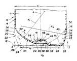
- FIG. 3is a bottom plan view of the container taken along the direction of line 3 — 3 in FIG. 2 to further illustrate the construction of the freestanding base structure;
- FIG. 4is a sectional view taken along the direction of line 4 — 4 in FIG. 2 to illustrate the construction of ribs that are located between legs of the freestanding base structure;
- FIG. 5is a sectional view similar to FIG. 2 but illustrating another embodiment of the blow molded container wherein the central round hub of the freestanding base structure has a generally flat shape that extends horizontally;
- FIG. 6is a bottom plan view of the container taken along the direction of line 6 — 6 in FIG. 5;
- FIG. 7is a sectional view taken in the same direction as FIGS. 2 and 5 but illustrating a further embodiment wherein the central round hub of the freestanding base structure has a downwardly extending construction;
- FIG. 8is a bottom plan view taken along the direction of line 8 — 8 of FIG. 7 .
- a plastic blow molded container constructed in accordance with the present inventionis generally indicated by 10 and has a central axis A that extends vertically with the container supported on a horizontal surface 12 as shown.
- the plastic blow molded container 10includes a cylindrical body portion 14 that extends vertically about the central axis A with a diameter D.
- An upper end closure 16 of the containeris unitary with the upper extremity of the cylindrical body portion 14 and includes a dispensing spout which is illustrated as having a thread 18 for securing an unshown cap-type closure.
- the containeralso includes a freestanding base structure 20 constructed according to the present invention and unitary with the cylindrical body portion 14 to close its lower extremity.
- This freestanding base structure 20as is more fully hereinafter described has the capability to provide good stability against tipping, which is especially desirable when the container is empty and being conveyed upright after manufacturing thereof and during movement through a filling line, and the freestanding base structure is also capable of withstanding internal pressure such as when the container is filled with carbonated beverage as well as resisting stress cracking.
- the freestanding base structure 20includes a plurality of downwardly projecting hollow legs 22 spaced circumferentially from each other with respect to the body portion.
- Each leg 22has a lower flat foot 24 coplanar with the feet of the other legs to cooperate therewith in Supporting the container in an upright position such as shown in FIG. 1 .
- the lower flat feet 24have an outer diameter D f that preferably is at least 0.75 of the diameter D of the cylindrical body portion to provide good stability of the container against tipping.
- Each leg 22also has an outer wall 26 that extends from the outer extremity of the flat foot 24 thereof to the cylindrical body portion 14 .
- the flat foot 24 and the outer wall 26 of each leg 22have a curved junction 28 best shown in FIG. 2 .
- This junction 28has a radius of curvature R j at the outer surface of the container which preferably is less than 0.05 of the diameter D of the cylindrical body portion.
- Each leg 22also has an inner connecting portion 30 that is shown as planar and is inclined and extends upwardly and inwardly from the inner extremity of its flat foot 24 . As best shown in FIGS. 2 and 3, each leg 22 also has a pair of side walls 32 that cooperate with the lower foot 24 , the outer wall 26 and the inner planar connecting portion 30 to close the leg.
- the freestanding base structure 20also includes a plurality of curved ribs 34 spaced circumferentially from each other between the downwardly projecting legs 22 and connecting the adjacent side walls 32 of the legs.
- Each rib 34 as shown best in FIG. 2has an outer upper end 36 that has a circumferential width W u (FIG. 3) and extends upwardly for connection to the cylindrical body portion 14 of the container as shown in FIG. 2 .
- Each rib 34also has an inner lower end 38 located between the inner connecting portions 30 of the legs 22 on opposite sides thereof as shown in FIG. 3 and extending downwardly and inwardly toward the central axis A of the container.
- each rib 34has a circumferential width W l that as shown in FIG. 3 is larger than the circumferential width W u of the outer upper end 36 of the rib.
- each rib 34also has a curved intermediate portion 40 that extends between the outer upper and inner lower ends 36 and 38 thereof with an outwardly convex shape.
- the freestanding base structure 20 of the containeralso includes a generally round hub 41 located along the central axis A with the legs 22 and curved ribs 34 extending radially therefrom in a circumferentially alternating relationship to each other.
- This hub 41has a diameter D h in the range of about 0.15 to 0.25 of the diameter D of the cylindrical body portion.
- Hub 41includes a periphery having connections 42 to the upwardly extending planar inner connecting portions 30 of the legs, and the hub periphery also has connections 43 to the downwardly extending inner lower ends 38 of the curved ribs.
- the hub 41 of the freestanding base structurehas an upwardly extending shape whose periphery is connected to the upwardly extending planar inner connecting portions 30 of the legs and to the downwardly extending inner lower ends 38 of the curved ribs as described above.
- This upwardly extending hub 41includes a round upper wall 44 and an annular wall 46 having an upper end connected to the upper wall thereof and extending downwardly therefrom with an inclination of at least 45° with respect to the flat feet 24 of the legs 22 .
- Annular wall 46 of the hub 41also has a lower end that defines a periphery of the hub and is connected to the inner connecting portions 30 of the feet 22 and to the inner lower ends 38 of the curved ribs 34 .
- the upper wall 44 of the hub 41is spaced above the plane of the flat feet 24 of the legs 22 by a greater height than the hub periphery at the lower end of annular wall 46 .
- This freestanding base constructionensures that the preform from which the container is made can be expanded to define the junctions 28 between the outer extremities of the feet 24 and the outer walls 26 with a sufficiently thick wall thickness so as to have the requisite strength.
- the hub periphery at the lower end of the annular wall 46 of the hub 41is spaced above the plane of the flat feet 24 by a height H p sufficient to maintain the center of the container spaced upwardly from the surface 12 so that the sprue nub 48 , which is used in the injection molding of the preform utilized to blow mold the container, is spaced above the support surface 12 such that the feet 24 are maintained in their coplanar relationship in surface-to-surface engagement with the support surface.
- the curved intermediate portion 40 of each rib 34has a circumferential width that tapers from the inner lower end 38 thereof to the outer upper end 36 thereof with an included angle B in the range of about 1° to 8°. Most preferably, this included angle B defined by the curved intermediate portion 40 of each rib is about 2°.
- Such a taperprovides an inner lower end 38 of the rib with the circumferential width W l that is sufficiently large to carry the stresses involved at this location which is relatively unoriented during the blow molding process as compared to the outer portions of the container.
- the inner hub areawhich has material that is not as strong due to the lack of molecular orientation during the blow molding process has a greater cross sectional area to carry the stress and thereby prevent stress cracking adjacent the hub.
- the periphery of the hub 41 as previously mentionedis spaced above the plane of the flat feet 24 of the legs 22 by the height H p , and the ratio of the diameter D f over the height H p is in the range of about 25 to 90.
- Such a ratioprovides a construction with sufficient strength to maintain the hub 41 spaced upwardly from the surface 12 on which the base structure 20 of the container 10 is supported.
- each rib 34has its curved intermediate portion 40 provided with the included angle B of about 1° to 8° as well as having the ratio of the container diameter D f over the height H p of the hub in the range of about 25 to 90.
- FIGS. 5 and 6another embodiment of the container 10 ′ has much of the same construction as the previously described embodiment except as will be noted and thus has like reference numerals identifying like components thereof such that the previous description is applicable and need not be repeated.
- the hub 41 ′ of the freestanding base structure 20 ′ of this embodimenthas a generally flat shape that extends horizontally as opposed to an upwardly extending shape as with the previously described embodiment.
- This horizontally extending flat hub 41 ′has a periphery connected by the connections 42 to the upwardly extending planar inner connecting portions 30 of the legs and by the connections 43 to the downwardly extending inner lower ends 38 of the curved ribs 34 .
- These curved ribs 34like the previously described embodiment have the circumferential width W l of the inner lower end 38 larger than the circumferential width W u of the outer upper end 36 , and preferably the intermediate portion 40 of each rib has a tapering shape between these ends with angle B in the range of about 1° to 8° and most preferably about 2°.
- the flat hub 41 ′has its periphery spaced above the plane of the lower feet 24 by a height H p with the ratio of D f over H p being in the range of about 25 to 90 in the same manner as the previously described embodiment.
- This constructionprevents injection molding sprue nub 48 ′ from adversely affecting stability of the container by maintaining it above the support surface 12 .
- this embodiment of the container 10 ′ shown in FIGS. 5 and 6is the same as the previously described embodiment of FIGS. 1 through 4.
- FIGS. 7 and 8a further embodiment of the container 10 ′′ also has generally the same construction as the embodiment of FIGS. 1 through 4 except as will be noted such that like reference numerals are applied to like components thereof and much of the previous description is applicable and thus will not be repeated.
- the plastic blow molded container 10 ′′ illustrated in FIGS. 7 and 8has its generally round hub 41 ′′ located along the central axis A provided with a downwardly extending shape whose periphery is connected by the connections 42 to the upwardly extending planar inner connecting portions 30 of the legs and by the connections 43 to the downwardly extending inner ends 38 of the curved ribs. More specifically as best illustrated in FIG.
- the central hub 41 ′′preferably has a curved shape and most preferably has a radius of curvature R h that is less than one-half the radius of curvature R r of the curved intermediate portion 40 of each rib 34 .
- These curved ribs 34like the previously described embodiments have the circumferential width W l of the inner lower end 38 larger than the circumferential width W u of the outer upper end 36 , and preferably the intermediate portion 40 of each rib has a tapering shape between these ends with angle B in the range of about 1° to 8° and most preferably about 2°.
- the downwardly extending hub 41 ′′has its periphery spaced above the plane of the flat feet 24 by a height H p with the ratio of D f over H p being in the range of about 25 to 90 in the same manner as the previously described embodiments.
- This constructionspaces the injection molding sprue nub 48 ′′ above the support surface 12 so as not to adversely affect stability of the container.
- the radius of curvature Rh of the downwardly extending hub 41 ′′is about one-third the radius of curvature R r of the intermediate portion 40 of the rib 34 which, as is hereinafter described, is greater than about 0.6 of the diameter D of the cylindrical body portion 14 .
- the cylindrical body portion 14 of the container 10 , 10 ′ and 10 ′′has a nominal wall thickness t which is normally in the range of about 0.009 to 0.011 of an inch.
- the construction of the freestanding base structure 20has the inner extremities of the flat feet 24 , the inner connecting portions 30 of the legs, the inner lower ends 38 of the curved ribs 34 and the associated hub 41 , 41 ′ and 41 ′′ each provided with a wall thickness t′ that is at least 1.7 times the nominal wall thickness t of the cylindrical body portion and preferably about 2 times the nominal wall thickness t.
- each container embodimenthas its freestanding base structure constructed such that the lower flat foot 24 of each leg 22 has a truncated wedge shape whose truncated inner end terminates at the associated planar inner connecting portion 30 of the foot and whose curved outer end is defined at the junction 28 with the associated outer wall 26 .
- each container embodimenthas each rib 34 between the adjacent pair of leg side walls 32 provided with a flat cross section along the intermediate rib portion 40 between its ends.
- This flat cross section of each rib 34thus extends from its narrower outer upper end 36 along the tapering intermediate rib portion 40 to its wider inner lower end 38 at the junction with the lower end of the annular wall 46 of the hub 42 .
- the flat rib cross-section shown in FIG. 4is illustrative of the construction of each container embodiment 10 , 10 ′ and 10 ′′.
- each leg 22has a curved shape including an upper end 50 that is tangent with the adjacent portion of the lower extremity of the cylindrical body portion 14 of the container.
- the curvature of this outer wall 26 as well as the curvature of each rib 34constitute features that enable the freestanding base structure to have good stability as well as the strength to withstand internal pressure as part of the construction previously described.
- each foothas a radius of curvature R w greater than 0.75 of the diameter D of the cylindrical body portion so that the outer diameter D f of the flat feet 24 can be as large as possible when the junction 28 is constructed as described previously with a radius of curvature R j of less than 0.05 of the diameter D of the cylindrical body portion.
- each rib 34has a radius of curvature R r greater than about 0.6 of the diameter D of the cylindrical body portion and with a center of curvature on the opposite side of the central axis A from the rib.
- the freestanding base 20 of the container 10is disclosed as including an odd number of legs 22 and ribs 34 with each leg 22 located in a diametrically opposite relationship to the associated rib 34 about the central axis A. More specifically, the containers 10 , 10 ′ and 10 ′′ are each illustrated as including five legs 22 and five ribs 34 which is the preferred number so as to provide best stability against tipping such as when supported on refrigerator wire shelves or other discontinuous supports.
- blow molded containers 10 , 10 ′ and 10 ′′ shownare manufactured from polyethylene terephthalate by injection stretch blow molding. This produces a biaxially oriented container wall with increased strength and the capability of withstanding internal pressure when made with the freestanding base structure as described above.
Landscapes
- Engineering & Computer Science (AREA)
- Ceramic Engineering (AREA)
- Mechanical Engineering (AREA)
- Containers Having Bodies Formed In One Piece (AREA)
Abstract
Description
Claims (9)
Priority Applications (4)
| Application Number | Priority Date | Filing Date | Title |
|---|---|---|---|
| US09/886,644US6659299B2 (en) | 1990-11-15 | 2001-06-21 | Plastic blow molded freestanding container |
| US10/689,360US6908002B2 (en) | 1990-11-15 | 2003-10-20 | Plastic blow molded freestanding container |
| US11/123,322US7198163B2 (en) | 1990-11-15 | 2005-05-06 | Plastic blow molded freestanding container |
| US11/688,468US7520400B2 (en) | 1990-11-15 | 2007-03-20 | Plastic blow molded freestanding container |
Applications Claiming Priority (9)
| Application Number | Priority Date | Filing Date | Title |
|---|---|---|---|
| US07/614,220US5064080A (en) | 1990-11-15 | 1990-11-15 | Plastic blow molded freestanding container |
| US07/771,636US5139162A (en) | 1990-11-15 | 1991-10-04 | Plastic blow molded freestanding container |
| US07/915,072US5287978A (en) | 1990-11-15 | 1992-07-16 | Plastic blow molded freestanding container |
| US16646093A | 1993-12-14 | 1993-12-14 | |
| US08/631,034US5685446A (en) | 1990-11-15 | 1996-04-18 | Plastic blow molded freestanding container |
| US08/877,663US5850931A (en) | 1990-11-15 | 1997-06-18 | Plastic blow molded freestanding container |
| US21031898A | 1998-12-11 | 1998-12-11 | |
| US09/502,100US6260724B1 (en) | 1990-11-15 | 2000-02-10 | Plastic blow molded freestanding container |
| US09/886,644US6659299B2 (en) | 1990-11-15 | 2001-06-21 | Plastic blow molded freestanding container |
Related Parent Applications (1)
| Application Number | Title | Priority Date | Filing Date |
|---|---|---|---|
| US09/502,100ContinuationUS6260724B1 (en) | 1990-11-15 | 2000-02-10 | Plastic blow molded freestanding container |
Related Child Applications (1)
| Application Number | Title | Priority Date | Filing Date |
|---|---|---|---|
| US10/689,360ContinuationUS6908002B2 (en) | 1990-11-15 | 2003-10-20 | Plastic blow molded freestanding container |
Publications (2)
| Publication Number | Publication Date |
|---|---|
| US20010035391A1 US20010035391A1 (en) | 2001-11-01 |
| US6659299B2true US6659299B2 (en) | 2003-12-09 |
Family
ID=46250331
Family Applications (8)
| Application Number | Title | Priority Date | Filing Date |
|---|---|---|---|
| US08/429,946Expired - LifetimeUS5615790A (en) | 1990-11-15 | 1995-04-27 | Plastic blow molded freestanding container |
| US08/631,034Expired - LifetimeUS5685446A (en) | 1990-11-15 | 1996-04-18 | Plastic blow molded freestanding container |
| US08/877,663Expired - LifetimeUS5850931A (en) | 1990-11-15 | 1997-06-18 | Plastic blow molded freestanding container |
| US09/502,100Expired - Fee RelatedUS6260724B1 (en) | 1990-11-15 | 2000-02-10 | Plastic blow molded freestanding container |
| US09/886,644Expired - Fee RelatedUS6659299B2 (en) | 1990-11-15 | 2001-06-21 | Plastic blow molded freestanding container |
| US10/689,360Expired - Fee RelatedUS6908002B2 (en) | 1990-11-15 | 2003-10-20 | Plastic blow molded freestanding container |
| US11/123,322Expired - Fee RelatedUS7198163B2 (en) | 1990-11-15 | 2005-05-06 | Plastic blow molded freestanding container |
| US11/688,468Expired - Fee RelatedUS7520400B2 (en) | 1990-11-15 | 2007-03-20 | Plastic blow molded freestanding container |
Family Applications Before (4)
| Application Number | Title | Priority Date | Filing Date |
|---|---|---|---|
| US08/429,946Expired - LifetimeUS5615790A (en) | 1990-11-15 | 1995-04-27 | Plastic blow molded freestanding container |
| US08/631,034Expired - LifetimeUS5685446A (en) | 1990-11-15 | 1996-04-18 | Plastic blow molded freestanding container |
| US08/877,663Expired - LifetimeUS5850931A (en) | 1990-11-15 | 1997-06-18 | Plastic blow molded freestanding container |
| US09/502,100Expired - Fee RelatedUS6260724B1 (en) | 1990-11-15 | 2000-02-10 | Plastic blow molded freestanding container |
Family Applications After (3)
| Application Number | Title | Priority Date | Filing Date |
|---|---|---|---|
| US10/689,360Expired - Fee RelatedUS6908002B2 (en) | 1990-11-15 | 2003-10-20 | Plastic blow molded freestanding container |
| US11/123,322Expired - Fee RelatedUS7198163B2 (en) | 1990-11-15 | 2005-05-06 | Plastic blow molded freestanding container |
| US11/688,468Expired - Fee RelatedUS7520400B2 (en) | 1990-11-15 | 2007-03-20 | Plastic blow molded freestanding container |
Country Status (1)
| Country | Link |
|---|---|
| US (8) | US5615790A (en) |
Cited By (1)
| Publication number | Priority date | Publication date | Assignee | Title |
|---|---|---|---|---|
| US20040079721A1 (en)* | 1990-11-15 | 2004-04-29 | Plastipak Packaging, Inc. | Plastic blow molded freestanding container |
Families Citing this family (69)
| Publication number | Priority date | Publication date | Assignee | Title |
|---|---|---|---|---|
| US6019236A (en) | 1997-09-10 | 2000-02-01 | Plastipak Packaging, Inc. | Plastic blow molded container having stable freestanding base |
| US5988416A (en) | 1998-07-10 | 1999-11-23 | Crown Cork & Seal Technologies Corporation | Footed container and base therefor |
| US6296471B1 (en)* | 1998-08-26 | 2001-10-02 | Crown Cork & Seal Technologies Corporation | Mold used to form a footed container and base therefor |
| US6085924A (en)* | 1998-09-22 | 2000-07-11 | Ball Corporation | Plastic container for carbonated beverages |
| USD442831S1 (en) | 1999-10-25 | 2001-05-29 | Willie Jacobs | Tilted soup bowl |
| US20040173565A1 (en)* | 1999-12-01 | 2004-09-09 | Frank Semersky | Pasteurizable wide-mouth container |
| US6269962B1 (en)* | 2000-01-21 | 2001-08-07 | Colgate-Palmolive Company | Enhanced strength container |
| US6378723B1 (en) | 2000-02-05 | 2002-04-30 | J. P. Casey | Container having bottom lug for radial positioning and bottom mold therefor |
| US7178687B1 (en) | 2000-04-06 | 2007-02-20 | Consolidated Container Company Lp | Moldable plastic container with hourglass profile |
| US8584879B2 (en) | 2000-08-31 | 2013-11-19 | Co2Pac Limited | Plastic container having a deep-set invertible base and related methods |
| NZ521694A (en) | 2002-09-30 | 2005-05-27 | Co2 Pac Ltd | Container structure for removal of vacuum pressure |
| US10435223B2 (en) | 2000-08-31 | 2019-10-08 | Co2Pac Limited | Method of handling a plastic container having a moveable base |
| US10246238B2 (en) | 2000-08-31 | 2019-04-02 | Co2Pac Limited | Plastic container having a deep-set invertible base and related methods |
| US20030196926A1 (en)* | 2001-04-19 | 2003-10-23 | Tobias John W. | Multi-functional base for a plastic, wide-mouth, blow-molded container |
| US8127955B2 (en) | 2000-08-31 | 2012-03-06 | John Denner | Container structure for removal of vacuum pressure |
| US7543713B2 (en) | 2001-04-19 | 2009-06-09 | Graham Packaging Company L.P. | Multi-functional base for a plastic, wide-mouth, blow-molded container |
| US8381940B2 (en) | 2002-09-30 | 2013-02-26 | Co2 Pac Limited | Pressure reinforced plastic container having a moveable pressure panel and related method of processing a plastic container |
| TWI228476B (en) | 2000-08-31 | 2005-03-01 | Co2 Pac Ltd | Semi-rigid collapsible container |
| US7900425B2 (en) | 2005-10-14 | 2011-03-08 | Graham Packaging Company, L.P. | Method for handling a hot-filled container having a moveable portion to reduce a portion of a vacuum created therein |
| US6409035B1 (en) | 2000-11-28 | 2002-06-25 | Plastipak Packaging, Inc. | Hollow plastic bottles |
| US6640989B2 (en) | 2001-02-08 | 2003-11-04 | Inoac Packaging Group Inc. | Composite container with integral support, related method and mold |
| FR2822804B1 (en)* | 2001-04-03 | 2004-06-04 | Sidel Sa | CONTAINER, ESPECIALLY BOTTLED, IN THERMOPLASTIC MATERIAL WHOSE BOTTOM HAS A CROSS FOOTPRINT |
| JP2004526642A (en) | 2001-04-19 | 2004-09-02 | グラハム・パツケージング・カンパニー・エル・ピー | Multifunctional base for blow molded plastic wide mouth containers |
| USD476896S1 (en) | 2001-09-17 | 2003-07-08 | Crown Cork & Seal Technologies Corporation | Container base |
| USD520142S1 (en) | 2002-03-15 | 2006-05-02 | Baby Innovations Marketing E | Teat |
| US9969517B2 (en) | 2002-09-30 | 2018-05-15 | Co2Pac Limited | Systems and methods for handling plastic containers having a deep-set invertible base |
| NZ569422A (en) | 2003-07-30 | 2010-02-26 | Graham Packaging Co | Container filling with base projection inverted during transportation, and being pushed up after filling |
| JP4769791B2 (en) | 2004-03-11 | 2011-09-07 | グラハム パッケージング カンパニー,エル ピー | Plastic container transport method |
| US10611544B2 (en) | 2004-07-30 | 2020-04-07 | Co2Pac Limited | Method of handling a plastic container having a moveable base |
| US20060131257A1 (en)* | 2004-12-20 | 2006-06-22 | Ball Corporation | Plastic container with champagne style base |
| US8017065B2 (en) | 2006-04-07 | 2011-09-13 | Graham Packaging Company L.P. | System and method for forming a container having a grip region |
| US8075833B2 (en) | 2005-04-15 | 2011-12-13 | Graham Packaging Company L.P. | Method and apparatus for manufacturing blow molded containers |
| CA2552105A1 (en)* | 2005-07-12 | 2007-01-12 | Pretium Packaging, Llc | Container with improved crush resistance |
| USD539661S1 (en) | 2005-07-12 | 2007-04-03 | Pretium Packaging, Llc | Container |
| US7461756B2 (en) | 2005-08-08 | 2008-12-09 | Plastipak Packaging, Inc. | Plastic container having a freestanding, self-supporting base |
| US7799264B2 (en) | 2006-03-15 | 2010-09-21 | Graham Packaging Company, L.P. | Container and method for blowmolding a base in a partial vacuum pressure reduction setup |
| US9707711B2 (en) | 2006-04-07 | 2017-07-18 | Graham Packaging Company, L.P. | Container having outwardly blown, invertible deep-set grips |
| US8747727B2 (en) | 2006-04-07 | 2014-06-10 | Graham Packaging Company L.P. | Method of forming container |
| US20090230153A1 (en)* | 2006-07-27 | 2009-09-17 | Knight John B | Dispensing Package and Methods of Using and Making |
| US20080023499A1 (en)* | 2006-07-27 | 2008-01-31 | Knight John B | Dispensing package and methods of using and making |
| FR2910438B1 (en)* | 2006-12-21 | 2010-12-10 | Evian Saeme Sa | CHAMPAGNE BOTTLE PLASTIC BOTTLE AND MANUFACTURING METHOD THEREOF |
| US11897656B2 (en) | 2007-02-09 | 2024-02-13 | Co2Pac Limited | Plastic container having a movable base |
| US11731823B2 (en) | 2007-02-09 | 2023-08-22 | Co2Pac Limited | Method of handling a plastic container having a moveable base |
| US7891513B2 (en)* | 2007-06-08 | 2011-02-22 | Amcor Limited | Container base with feet |
| US8439223B2 (en)* | 2007-08-20 | 2013-05-14 | The Procter & Gamble Company | Base cup for a supportable pressurizable container |
| US20090050599A1 (en)* | 2007-08-20 | 2009-02-26 | Matthew John Martin | Supportable pressurizable container having a bottom for receiving a dip tube and base cup therefor |
| US20090050598A1 (en)* | 2007-08-20 | 2009-02-26 | Chow-Chi Huang | Supportable pressurizable container and base cup therefor |
| US9061795B2 (en)* | 2007-08-20 | 2015-06-23 | Procter & Gamble | Supportable pressurizable container and base cup therefor with alignment tabs |
| FR2932458B1 (en)* | 2008-06-13 | 2010-08-20 | Sidel Participations | CONTAINER, IN PARTICULAR BOTTLE, IN THERMOPLASTIC MATERIAL EQUIPPED WITH A REINFORCED BACKGROUND |
| US8627944B2 (en) | 2008-07-23 | 2014-01-14 | Graham Packaging Company L.P. | System, apparatus, and method for conveying a plurality of containers |
| US8636944B2 (en) | 2008-12-08 | 2014-01-28 | Graham Packaging Company L.P. | Method of making plastic container having a deep-inset base |
| US7926243B2 (en) | 2009-01-06 | 2011-04-19 | Graham Packaging Company, L.P. | Method and system for handling containers |
| GB2473256B (en)* | 2009-09-07 | 2012-04-04 | Michael Pritchard | A water container |
| AT510506B1 (en)* | 2010-09-22 | 2013-01-15 | Red Bull Gmbh | FLOOR CONSTRUCTION FOR A PLASTIC BOTTLE |
| US8962114B2 (en) | 2010-10-30 | 2015-02-24 | Graham Packaging Company, L.P. | Compression molded preform for forming invertible base hot-fill container, and systems and methods thereof |
| US9133006B2 (en) | 2010-10-31 | 2015-09-15 | Graham Packaging Company, L.P. | Systems, methods, and apparatuses for cooling hot-filled containers |
| FR2967975B1 (en)* | 2010-11-25 | 2012-12-28 | Sidel Participations | PETALOIDE COMBINED CONTAINER BASE |
| DE102010064125A1 (en)* | 2010-12-23 | 2012-06-28 | Krones Aktiengesellschaft | Container made of a thermoplastic material |
| US9150320B2 (en) | 2011-08-15 | 2015-10-06 | Graham Packaging Company, L.P. | Plastic containers having base configurations with up-stand walls having a plurality of rings, and systems, methods, and base molds thereof |
| US9994378B2 (en) | 2011-08-15 | 2018-06-12 | Graham Packaging Company, L.P. | Plastic containers, base configurations for plastic containers, and systems, methods, and base molds thereof |
| US8919587B2 (en) | 2011-10-03 | 2014-12-30 | Graham Packaging Company, L.P. | Plastic container with angular vacuum panel and method of same |
| FR2991302B1 (en)* | 2012-05-31 | 2014-07-04 | Sidel Participations | CONTAINER HAVING A BACKGROUND PROVIDED WITH A DECOUCHEMENT VOUTE |
| USD760590S1 (en) | 2013-01-25 | 2016-07-05 | S.C. Johnson & Son, Inc. | Bottle |
| US9022776B2 (en) | 2013-03-15 | 2015-05-05 | Graham Packaging Company, L.P. | Deep grip mechanism within blow mold hanger and related methods and bottles |
| US9254937B2 (en) | 2013-03-15 | 2016-02-09 | Graham Packaging Company, L.P. | Deep grip mechanism for blow mold and related methods and bottles |
| BR112016012545B1 (en) | 2013-12-03 | 2020-12-15 | Amcor Rigid Plastics Usa, Llc | FOOT CONTAINER BASE |
| USD859994S1 (en) | 2017-10-23 | 2019-09-17 | Pretium Packaging, L.L.C. | Container |
| USD847653S1 (en) | 2017-10-23 | 2019-05-07 | Pretium Packaging, L.L.C. | Container |
| USD846992S1 (en) | 2017-10-23 | 2019-04-30 | Pretium Packaging, L.L.C. | Container |
Citations (54)
| Publication number | Priority date | Publication date | Assignee | Title |
|---|---|---|---|---|
| US3598270A (en) | 1969-04-14 | 1971-08-10 | Continental Can Co | Bottom end structure for plastic containers |
| US3727783A (en) | 1971-06-15 | 1973-04-17 | Du Pont | Noneverting bottom for thermoplastic bottles |
| US3759410A (en) | 1971-12-15 | 1973-09-18 | Owens Illinois Inc | Pressure resistant plastic container |
| US3871541A (en) | 1973-02-26 | 1975-03-18 | Continental Can Co | Bottom structure for plastic containers |
| US3935955A (en) | 1975-02-13 | 1976-02-03 | Continental Can Company, Inc. | Container bottom structure |
| US4108324A (en) | 1977-05-23 | 1978-08-22 | The Continental Group, Inc. | Ribbed bottom structure for plastic container |
| DE2920122A1 (en) | 1979-05-18 | 1980-11-20 | Voith Fischer Kunststofftech | Blow moulded plastic bottle for pressurised liquid - with five-lobed support sectors on bottom |
| US4247012A (en)* | 1979-08-13 | 1981-01-27 | Sewell Plastics, Inc. | Bottom structure for plastic container for pressurized fluids |
| US4249667A (en)* | 1979-10-25 | 1981-02-10 | The Continental Group, Inc. | Plastic container with a generally hemispherical bottom wall having hollow legs projecting therefrom |
| US4254882A (en) | 1978-09-08 | 1981-03-10 | Yoshino Kogyosho Co., Ltd. | Plastic pressure bottle |
| US4267144A (en) | 1979-07-03 | 1981-05-12 | The Continental Group, Inc. | Process of reducing blowing cycle for blow molded containers |
| US4276987A (en)* | 1979-02-07 | 1981-07-07 | Solvay & Cie | Hollow body made of an oriented thermoplastic |
| US4294366A (en) | 1980-03-17 | 1981-10-13 | Owens-Illinois, Inc. | Free-standing plastic bottle |
| US4318489A (en) | 1980-07-31 | 1982-03-09 | Pepsico, Inc. | Plastic bottle |
| US4335821A (en)* | 1979-07-03 | 1982-06-22 | The Continental Group, Inc. | Blow molded plastic material bottle bottom |
| US4368825A (en) | 1980-11-28 | 1983-01-18 | Standard Oil Company (Indiana) | Self-standing bottle structure |
| US4598831A (en) | 1983-10-31 | 1986-07-08 | Nissei Asb Machine Co., Ltd. | Heat-resistant synthetic resin bottle |
| WO1986005462A1 (en) | 1985-03-21 | 1986-09-25 | Meri-Mate Limited | Improvements in or relating to plastics containers |
| EP0219696A2 (en) | 1985-10-22 | 1987-04-29 | Unilever N.V. | Plastic hollow body |
| EP0225155A2 (en)* | 1985-11-27 | 1987-06-10 | Embee Limited | Bottle |
| GB2189214A (en) | 1986-04-21 | 1987-10-21 | Fibrenyle Ltd | Blow-moulded containers |
| US4785950A (en) | 1986-03-12 | 1988-11-22 | Continental Pet Technologies, Inc. | Plastic bottle base reinforcement |
| US4785949A (en)* | 1987-12-11 | 1988-11-22 | Continental Pet Technologies, Inc. | Base configuration for an internally pressurized container |
| US4785948A (en) | 1987-02-03 | 1988-11-22 | Herbert Strassheimer | Blow molded plastic container having a reinforced wall structure and preform therefor |
| JPH0199949A (en) | 1987-10-09 | 1989-04-18 | Toyo Seikan Kaisha Ltd | Plastic pressure container |
| US4850494A (en) | 1988-06-20 | 1989-07-25 | Hoover Universal, Inc. | Blow molded container with self-supporting base reinforced by hollow ribs |
| US4850493A (en) | 1988-06-20 | 1989-07-25 | Hoover Universal, Inc. | Blow molded bottle with self-supporting base reinforced by hollow ribs |
| US4865206A (en)* | 1988-06-17 | 1989-09-12 | Hoover Universal, Inc. | Blow molded one-piece bottle |
| US4867323A (en) | 1988-07-15 | 1989-09-19 | Hoover Universal, Inc. | Blow molded bottle with improved self supporting base |
| US4889752A (en) | 1987-05-29 | 1989-12-26 | Devtech, Inc. | One piece self-standing blow molded plastic containers |
| US4892205A (en) | 1988-07-15 | 1990-01-09 | Hoover Universal, Inc. | Concentric ribbed preform and bottle made from same |
| US4910054A (en) | 1988-12-01 | 1990-03-20 | Continental Pet Technologies, Inc. | Plastic preform having reinforced container base forming portion and container formed therefrom |
| EP0385693A1 (en) | 1989-02-27 | 1990-09-05 | Embee Limited | A plastics bottle |
| US4978015A (en)* | 1990-01-10 | 1990-12-18 | North American Container, Inc. | Plastic container for pressurized fluids |
| US5024340A (en) | 1990-07-23 | 1991-06-18 | Sewell Plastics, Inc. | Wide stance footed bottle |
| US5064080A (en) | 1990-11-15 | 1991-11-12 | Plastipak Packaging, Inc. | Plastic blow molded freestanding container |
| JPH03275431A (en)* | 1990-03-14 | 1991-12-06 | Denki Kagaku Kogyo Kk | Self-supported pressure vessel |
| US5072841A (en) | 1986-02-14 | 1991-12-17 | Norderney Investments Limited | Plastic containers |
| WO1992000880A1 (en) | 1990-07-09 | 1992-01-23 | S.C.I. Operations Pty Limited Trading As Smorgon Plastics | An improved container |
| JPH0444943A (en) | 1990-06-04 | 1992-02-14 | Toyo Seikan Kaisha Ltd | Pressure-resistant plastic bottle having resistance to stress-cracking and resistance to rocking |
| US5133468A (en) | 1991-06-14 | 1992-07-28 | Constar Plastics Inc. | Footed hot-fill container |
| US5139162A (en) | 1990-11-15 | 1992-08-18 | Plastipak Packaging, Inc. | Plastic blow molded freestanding container |
| JPH0565165A (en)* | 1991-09-06 | 1993-03-19 | Dainippon Printing Co Ltd | Pressure-resistant and self-standing container and manufacture of the same |
| US5205434A (en) | 1992-06-09 | 1993-04-27 | Constar Plastics, Inc. | Footed container |
| JPH05254529A (en)* | 1992-03-13 | 1993-10-05 | Hokkai Can Co Ltd | Bottle made of polyethylene terephthalate resin |
| US5261543A (en) | 1991-07-30 | 1993-11-16 | Sipa S.P.A. | Plastic bottle for containing both under-pressure and non under-pressure liquids |
| US5287978A (en) | 1990-11-15 | 1994-02-22 | Plastipak Packaging, Inc. | Plastic blow molded freestanding container |
| US5320230A (en) | 1992-06-08 | 1994-06-14 | Yuan Fang Limited | Base configuration for biaxial stretched blow molded pet containers |
| US5615790A (en) | 1990-11-15 | 1997-04-01 | Plastipak Packaging, Inc. | Plastic blow molded freestanding container |
| US5664695A (en) | 1995-01-06 | 1997-09-09 | Plastipak Packaging, Inc. | Plastic blow molded freestanding container |
| US5803290A (en) | 1996-08-12 | 1998-09-08 | Plastipak Packaging, Inc. | Plastic blow molded bottle having annular grip |
| US5829614A (en) | 1992-07-07 | 1998-11-03 | Continental Pet Technologies, Inc. | Method of forming container with high-crystallinity sidewall and low-crystallinity base |
| US6019236A (en) | 1997-09-10 | 2000-02-01 | Plastipak Packaging, Inc. | Plastic blow molded container having stable freestanding base |
| JP3275431B2 (en) | 1993-03-25 | 2002-04-15 | ダイキン工業株式会社 | Fluororesin molded article and method for producing the same |
Family Cites Families (4)
| Publication number | Priority date | Publication date | Assignee | Title |
|---|---|---|---|---|
| FR1489938A (en)* | 1965-07-28 | 1967-07-28 | Bristol Siddeley Engines Ltd | Joint device between rotating parts |
| US3935953A (en)* | 1974-06-24 | 1976-02-03 | Caterpillar Tractor Co. | Implement mounting means for earthworking vehicles |
| US5216543A (en)* | 1987-03-04 | 1993-06-01 | Minnesota Mining And Manufacturing Company | Apparatus and method for patterning a film |
| US5216548A (en)* | 1991-12-10 | 1993-06-01 | Industrial Technology Research Institute | Compound lens system |
- 1995
- 1995-04-27USUS08/429,946patent/US5615790A/ennot_activeExpired - Lifetime
- 1996
- 1996-04-18USUS08/631,034patent/US5685446A/ennot_activeExpired - Lifetime
- 1997
- 1997-06-18USUS08/877,663patent/US5850931A/ennot_activeExpired - Lifetime
- 2000
- 2000-02-10USUS09/502,100patent/US6260724B1/ennot_activeExpired - Fee Related
- 2001
- 2001-06-21USUS09/886,644patent/US6659299B2/ennot_activeExpired - Fee Related
- 2003
- 2003-10-20USUS10/689,360patent/US6908002B2/ennot_activeExpired - Fee Related
- 2005
- 2005-05-06USUS11/123,322patent/US7198163B2/ennot_activeExpired - Fee Related
- 2007
- 2007-03-20USUS11/688,468patent/US7520400B2/ennot_activeExpired - Fee Related
Patent Citations (56)
| Publication number | Priority date | Publication date | Assignee | Title |
|---|---|---|---|---|
| US3598270A (en) | 1969-04-14 | 1971-08-10 | Continental Can Co | Bottom end structure for plastic containers |
| US3727783A (en) | 1971-06-15 | 1973-04-17 | Du Pont | Noneverting bottom for thermoplastic bottles |
| US3759410A (en) | 1971-12-15 | 1973-09-18 | Owens Illinois Inc | Pressure resistant plastic container |
| US3871541A (en) | 1973-02-26 | 1975-03-18 | Continental Can Co | Bottom structure for plastic containers |
| US3935955A (en) | 1975-02-13 | 1976-02-03 | Continental Can Company, Inc. | Container bottom structure |
| US4108324A (en) | 1977-05-23 | 1978-08-22 | The Continental Group, Inc. | Ribbed bottom structure for plastic container |
| US4254882A (en) | 1978-09-08 | 1981-03-10 | Yoshino Kogyosho Co., Ltd. | Plastic pressure bottle |
| US4276987A (en)* | 1979-02-07 | 1981-07-07 | Solvay & Cie | Hollow body made of an oriented thermoplastic |
| DE2920122A1 (en) | 1979-05-18 | 1980-11-20 | Voith Fischer Kunststofftech | Blow moulded plastic bottle for pressurised liquid - with five-lobed support sectors on bottom |
| US4335821A (en)* | 1979-07-03 | 1982-06-22 | The Continental Group, Inc. | Blow molded plastic material bottle bottom |
| US4267144A (en) | 1979-07-03 | 1981-05-12 | The Continental Group, Inc. | Process of reducing blowing cycle for blow molded containers |
| US4247012A (en)* | 1979-08-13 | 1981-01-27 | Sewell Plastics, Inc. | Bottom structure for plastic container for pressurized fluids |
| US4249667A (en)* | 1979-10-25 | 1981-02-10 | The Continental Group, Inc. | Plastic container with a generally hemispherical bottom wall having hollow legs projecting therefrom |
| US4294366A (en) | 1980-03-17 | 1981-10-13 | Owens-Illinois, Inc. | Free-standing plastic bottle |
| US4318489A (en) | 1980-07-31 | 1982-03-09 | Pepsico, Inc. | Plastic bottle |
| US4368825A (en) | 1980-11-28 | 1983-01-18 | Standard Oil Company (Indiana) | Self-standing bottle structure |
| US4598831A (en) | 1983-10-31 | 1986-07-08 | Nissei Asb Machine Co., Ltd. | Heat-resistant synthetic resin bottle |
| WO1986005462A1 (en) | 1985-03-21 | 1986-09-25 | Meri-Mate Limited | Improvements in or relating to plastics containers |
| EP0219696A2 (en) | 1985-10-22 | 1987-04-29 | Unilever N.V. | Plastic hollow body |
| EP0225155A2 (en)* | 1985-11-27 | 1987-06-10 | Embee Limited | Bottle |
| US5072841A (en) | 1986-02-14 | 1991-12-17 | Norderney Investments Limited | Plastic containers |
| US4785950A (en) | 1986-03-12 | 1988-11-22 | Continental Pet Technologies, Inc. | Plastic bottle base reinforcement |
| GB2189214A (en) | 1986-04-21 | 1987-10-21 | Fibrenyle Ltd | Blow-moulded containers |
| US4785948A (en) | 1987-02-03 | 1988-11-22 | Herbert Strassheimer | Blow molded plastic container having a reinforced wall structure and preform therefor |
| US4889752A (en) | 1987-05-29 | 1989-12-26 | Devtech, Inc. | One piece self-standing blow molded plastic containers |
| JPH0199949A (en) | 1987-10-09 | 1989-04-18 | Toyo Seikan Kaisha Ltd | Plastic pressure container |
| US4785949A (en)* | 1987-12-11 | 1988-11-22 | Continental Pet Technologies, Inc. | Base configuration for an internally pressurized container |
| US4865206A (en)* | 1988-06-17 | 1989-09-12 | Hoover Universal, Inc. | Blow molded one-piece bottle |
| US4850494A (en) | 1988-06-20 | 1989-07-25 | Hoover Universal, Inc. | Blow molded container with self-supporting base reinforced by hollow ribs |
| US4850493A (en) | 1988-06-20 | 1989-07-25 | Hoover Universal, Inc. | Blow molded bottle with self-supporting base reinforced by hollow ribs |
| US4892205A (en) | 1988-07-15 | 1990-01-09 | Hoover Universal, Inc. | Concentric ribbed preform and bottle made from same |
| US4867323A (en) | 1988-07-15 | 1989-09-19 | Hoover Universal, Inc. | Blow molded bottle with improved self supporting base |
| US4910054A (en) | 1988-12-01 | 1990-03-20 | Continental Pet Technologies, Inc. | Plastic preform having reinforced container base forming portion and container formed therefrom |
| EP0385693A1 (en) | 1989-02-27 | 1990-09-05 | Embee Limited | A plastics bottle |
| US4978015A (en)* | 1990-01-10 | 1990-12-18 | North American Container, Inc. | Plastic container for pressurized fluids |
| JPH03275431A (en)* | 1990-03-14 | 1991-12-06 | Denki Kagaku Kogyo Kk | Self-supported pressure vessel |
| JPH0444943A (en) | 1990-06-04 | 1992-02-14 | Toyo Seikan Kaisha Ltd | Pressure-resistant plastic bottle having resistance to stress-cracking and resistance to rocking |
| WO1992000880A1 (en) | 1990-07-09 | 1992-01-23 | S.C.I. Operations Pty Limited Trading As Smorgon Plastics | An improved container |
| US5024340A (en) | 1990-07-23 | 1991-06-18 | Sewell Plastics, Inc. | Wide stance footed bottle |
| US5615790A (en) | 1990-11-15 | 1997-04-01 | Plastipak Packaging, Inc. | Plastic blow molded freestanding container |
| US5064080A (en) | 1990-11-15 | 1991-11-12 | Plastipak Packaging, Inc. | Plastic blow molded freestanding container |
| US5139162A (en) | 1990-11-15 | 1992-08-18 | Plastipak Packaging, Inc. | Plastic blow molded freestanding container |
| US5850931A (en) | 1990-11-15 | 1998-12-22 | Plastipak Packaging, Inc. | Plastic blow molded freestanding container |
| US5685446A (en) | 1990-11-15 | 1997-11-11 | Plastipak Packaging, Inc. | Plastic blow molded freestanding container |
| US5287978A (en) | 1990-11-15 | 1994-02-22 | Plastipak Packaging, Inc. | Plastic blow molded freestanding container |
| US5133468A (en) | 1991-06-14 | 1992-07-28 | Constar Plastics Inc. | Footed hot-fill container |
| US5261543A (en) | 1991-07-30 | 1993-11-16 | Sipa S.P.A. | Plastic bottle for containing both under-pressure and non under-pressure liquids |
| JPH0565165A (en)* | 1991-09-06 | 1993-03-19 | Dainippon Printing Co Ltd | Pressure-resistant and self-standing container and manufacture of the same |
| JPH05254529A (en)* | 1992-03-13 | 1993-10-05 | Hokkai Can Co Ltd | Bottle made of polyethylene terephthalate resin |
| US5320230A (en) | 1992-06-08 | 1994-06-14 | Yuan Fang Limited | Base configuration for biaxial stretched blow molded pet containers |
| US5205434A (en) | 1992-06-09 | 1993-04-27 | Constar Plastics, Inc. | Footed container |
| US5829614A (en) | 1992-07-07 | 1998-11-03 | Continental Pet Technologies, Inc. | Method of forming container with high-crystallinity sidewall and low-crystallinity base |
| JP3275431B2 (en) | 1993-03-25 | 2002-04-15 | ダイキン工業株式会社 | Fluororesin molded article and method for producing the same |
| US5664695A (en) | 1995-01-06 | 1997-09-09 | Plastipak Packaging, Inc. | Plastic blow molded freestanding container |
| US5803290A (en) | 1996-08-12 | 1998-09-08 | Plastipak Packaging, Inc. | Plastic blow molded bottle having annular grip |
| US6019236A (en) | 1997-09-10 | 2000-02-01 | Plastipak Packaging, Inc. | Plastic blow molded container having stable freestanding base |
Cited By (6)
| Publication number | Priority date | Publication date | Assignee | Title |
|---|---|---|---|---|
| US20040079721A1 (en)* | 1990-11-15 | 2004-04-29 | Plastipak Packaging, Inc. | Plastic blow molded freestanding container |
| US6908002B2 (en)* | 1990-11-15 | 2005-06-21 | Plastipak Packaging, Inc. | Plastic blow molded freestanding container |
| US20050199578A1 (en)* | 1990-11-15 | 2005-09-15 | Plastipak Packaging, Inc. | Plastic blow molded freestanding container |
| US7198163B2 (en) | 1990-11-15 | 2007-04-03 | Plastipak Packaging, Inc. | Plastic blow molded freestanding container |
| US20070158299A1 (en)* | 1990-11-15 | 2007-07-12 | Plastipak Packaging, Inc. | Plastic blow molded freestanding container |
| US7520400B2 (en) | 1990-11-15 | 2009-04-21 | Plastipak Packaging, Inc. | Plastic blow molded freestanding container |
Also Published As
| Publication number | Publication date |
|---|---|
| US5685446A (en) | 1997-11-11 |
| US7198163B2 (en) | 2007-04-03 |
| US6908002B2 (en) | 2005-06-21 |
| US7520400B2 (en) | 2009-04-21 |
| US20050199578A1 (en) | 2005-09-15 |
| US5615790A (en) | 1997-04-01 |
| US6260724B1 (en) | 2001-07-17 |
| US20040079721A1 (en) | 2004-04-29 |
| US5850931A (en) | 1998-12-22 |
| US20010035391A1 (en) | 2001-11-01 |
| US20070158299A1 (en) | 2007-07-12 |
Similar Documents
| Publication | Publication Date | Title |
|---|---|---|
| US6659299B2 (en) | Plastic blow molded freestanding container | |
| US5287978A (en) | Plastic blow molded freestanding container | |
| US5064080A (en) | Plastic blow molded freestanding container | |
| US6019236A (en) | Plastic blow molded container having stable freestanding base | |
| US5139162A (en) | Plastic blow molded freestanding container | |
| US5664695A (en) | Plastic blow molded freestanding container | |
| CN1081419A (en) | The container that leg is arranged |
Legal Events
| Date | Code | Title | Description |
|---|---|---|---|
| AS | Assignment | Owner name:COMERICA BANK, AS AGENT, MICHIGAN Free format text:AMENDED AND RESTATED SECURITY AGREEMENT;ASSIGNORS:PLASTIPAK HOLDINGS, INC.;PLASTIPAK PACKAGING, INC.;WHITELINE EXPRESS, LTD.;AND OTHERS;REEL/FRAME:016418/0001 Effective date:20050128 | |
| FPAY | Fee payment | Year of fee payment:4 | |
| FPAY | Fee payment | Year of fee payment:8 | |
| REMI | Maintenance fee reminder mailed | ||
| LAPS | Lapse for failure to pay maintenance fees | ||
| STCH | Information on status: patent discontinuation | Free format text:PATENT EXPIRED DUE TO NONPAYMENT OF MAINTENANCE FEES UNDER 37 CFR 1.362 | |
| FP | Lapsed due to failure to pay maintenance fee | Effective date:20151209 | |
| AS | Assignment | Owner name:PLASTIPAK PACKAGING, INC., MICHIGAN Free format text:RELEASE BY SECURED PARTY;ASSIGNOR:COMERICA BANK, AS AGENT;REEL/FRAME:044485/0515 Effective date:20171012 Owner name:WHITELINE EXPRESS, LTD., MICHIGAN Free format text:RELEASE BY SECURED PARTY;ASSIGNOR:COMERICA BANK, AS AGENT;REEL/FRAME:044485/0515 Effective date:20171012 Owner name:CLEAN TECH, INC., MICHIGAN Free format text:RELEASE BY SECURED PARTY;ASSIGNOR:COMERICA BANK, AS AGENT;REEL/FRAME:044485/0515 Effective date:20171012 Owner name:PLASTIPAK HOLDINGS, INC., MICHIGAN Free format text:RELEASE BY SECURED PARTY;ASSIGNOR:COMERICA BANK, AS AGENT;REEL/FRAME:044485/0515 Effective date:20171012 Owner name:TABB REALTY, LLC, MICHIGAN Free format text:RELEASE BY SECURED PARTY;ASSIGNOR:COMERICA BANK, AS AGENT;REEL/FRAME:044485/0515 Effective date:20171012 |