US6659222B1 - Multi-chambered muffler - Google Patents
Multi-chambered mufflerDownload PDFInfo
- Publication number
- US6659222B1 US6659222B1US09/914,905US91490501AUS6659222B1US 6659222 B1US6659222 B1US 6659222B1US 91490501 AUS91490501 AUS 91490501AUS 6659222 B1US6659222 B1US 6659222B1
- Authority
- US
- United States
- Prior art keywords
- muffler
- baffle
- chamber
- outer shell
- tube
- Prior art date
- Legal status (The legal status is an assumption and is not a legal conclusion. Google has not performed a legal analysis and makes no representation as to the accuracy of the status listed.)
- Expired - Fee Related
Links
Images


Classifications
- F—MECHANICAL ENGINEERING; LIGHTING; HEATING; WEAPONS; BLASTING
- F01—MACHINES OR ENGINES IN GENERAL; ENGINE PLANTS IN GENERAL; STEAM ENGINES
- F01N—GAS-FLOW SILENCERS OR EXHAUST APPARATUS FOR MACHINES OR ENGINES IN GENERAL; GAS-FLOW SILENCERS OR EXHAUST APPARATUS FOR INTERNAL-COMBUSTION ENGINES
- F01N13/00—Exhaust or silencing apparatus characterised by constructional features
- F01N13/18—Construction facilitating manufacture, assembly, or disassembly
- F01N13/1872—Construction facilitating manufacture, assembly, or disassembly the assembly using stamp-formed parts or otherwise deformed sheet-metal
- F01N13/1877—Construction facilitating manufacture, assembly, or disassembly the assembly using stamp-formed parts or otherwise deformed sheet-metal the channels or tubes thereof being made integrally with the housing
- F—MECHANICAL ENGINEERING; LIGHTING; HEATING; WEAPONS; BLASTING
- F01—MACHINES OR ENGINES IN GENERAL; ENGINE PLANTS IN GENERAL; STEAM ENGINES
- F01N—GAS-FLOW SILENCERS OR EXHAUST APPARATUS FOR MACHINES OR ENGINES IN GENERAL; GAS-FLOW SILENCERS OR EXHAUST APPARATUS FOR INTERNAL-COMBUSTION ENGINES
- F01N1/00—Silencing apparatus characterised by method of silencing
- F01N1/02—Silencing apparatus characterised by method of silencing by using resonance
- F01N1/023—Helmholtz resonators
- F—MECHANICAL ENGINEERING; LIGHTING; HEATING; WEAPONS; BLASTING
- F01—MACHINES OR ENGINES IN GENERAL; ENGINE PLANTS IN GENERAL; STEAM ENGINES
- F01N—GAS-FLOW SILENCERS OR EXHAUST APPARATUS FOR MACHINES OR ENGINES IN GENERAL; GAS-FLOW SILENCERS OR EXHAUST APPARATUS FOR INTERNAL-COMBUSTION ENGINES
- F01N1/00—Silencing apparatus characterised by method of silencing
- F01N1/08—Silencing apparatus characterised by method of silencing by reducing exhaust energy by throttling or whirling
- F01N1/084—Silencing apparatus characterised by method of silencing by reducing exhaust energy by throttling or whirling the exhaust gases flowing through the silencer two or more times longitudinally in opposite directions, e.g. using parallel or concentric tubes
- F—MECHANICAL ENGINEERING; LIGHTING; HEATING; WEAPONS; BLASTING
- F01—MACHINES OR ENGINES IN GENERAL; ENGINE PLANTS IN GENERAL; STEAM ENGINES
- F01N—GAS-FLOW SILENCERS OR EXHAUST APPARATUS FOR MACHINES OR ENGINES IN GENERAL; GAS-FLOW SILENCERS OR EXHAUST APPARATUS FOR INTERNAL-COMBUSTION ENGINES
- F01N13/00—Exhaust or silencing apparatus characterised by constructional features
- F01N13/009—Exhaust or silencing apparatus characterised by constructional features having two or more separate purifying devices arranged in series
- F01N13/0097—Exhaust or silencing apparatus characterised by constructional features having two or more separate purifying devices arranged in series the purifying devices are arranged in a single housing
- F—MECHANICAL ENGINEERING; LIGHTING; HEATING; WEAPONS; BLASTING
- F01—MACHINES OR ENGINES IN GENERAL; ENGINE PLANTS IN GENERAL; STEAM ENGINES
- F01N—GAS-FLOW SILENCERS OR EXHAUST APPARATUS FOR MACHINES OR ENGINES IN GENERAL; GAS-FLOW SILENCERS OR EXHAUST APPARATUS FOR INTERNAL-COMBUSTION ENGINES
- F01N13/00—Exhaust or silencing apparatus characterised by constructional features
- F01N13/18—Construction facilitating manufacture, assembly, or disassembly
- F01N13/1872—Construction facilitating manufacture, assembly, or disassembly the assembly using stamp-formed parts or otherwise deformed sheet-metal
- F—MECHANICAL ENGINEERING; LIGHTING; HEATING; WEAPONS; BLASTING
- F01—MACHINES OR ENGINES IN GENERAL; ENGINE PLANTS IN GENERAL; STEAM ENGINES
- F01N—GAS-FLOW SILENCERS OR EXHAUST APPARATUS FOR MACHINES OR ENGINES IN GENERAL; GAS-FLOW SILENCERS OR EXHAUST APPARATUS FOR INTERNAL-COMBUSTION ENGINES
- F01N2470/00—Structure or shape of exhaust gas passages, pipes or tubes
- F01N2470/02—Tubes being perforated
- F—MECHANICAL ENGINEERING; LIGHTING; HEATING; WEAPONS; BLASTING
- F01—MACHINES OR ENGINES IN GENERAL; ENGINE PLANTS IN GENERAL; STEAM ENGINES
- F01N—GAS-FLOW SILENCERS OR EXHAUST APPARATUS FOR MACHINES OR ENGINES IN GENERAL; GAS-FLOW SILENCERS OR EXHAUST APPARATUS FOR INTERNAL-COMBUSTION ENGINES
- F01N2470/00—Structure or shape of exhaust gas passages, pipes or tubes
- F01N2470/06—Tubes being formed by assembly of stamped or otherwise deformed sheet-metal
- F—MECHANICAL ENGINEERING; LIGHTING; HEATING; WEAPONS; BLASTING
- F01—MACHINES OR ENGINES IN GENERAL; ENGINE PLANTS IN GENERAL; STEAM ENGINES
- F01N—GAS-FLOW SILENCERS OR EXHAUST APPARATUS FOR MACHINES OR ENGINES IN GENERAL; GAS-FLOW SILENCERS OR EXHAUST APPARATUS FOR INTERNAL-COMBUSTION ENGINES
- F01N2490/00—Structure, disposition or shape of gas-chambers
- F01N2490/14—Dead or resonance chambers connected to gas flow tube by relatively short side-tubes
- F—MECHANICAL ENGINEERING; LIGHTING; HEATING; WEAPONS; BLASTING
- F01—MACHINES OR ENGINES IN GENERAL; ENGINE PLANTS IN GENERAL; STEAM ENGINES
- F01N—GAS-FLOW SILENCERS OR EXHAUST APPARATUS FOR MACHINES OR ENGINES IN GENERAL; GAS-FLOW SILENCERS OR EXHAUST APPARATUS FOR INTERNAL-COMBUSTION ENGINES
- F01N2490/00—Structure, disposition or shape of gas-chambers
- F01N2490/15—Plurality of resonance or dead chambers
- F01N2490/155—Plurality of resonance or dead chambers being disposed one after the other in flow direction
Definitions
- This inventionrelates to exhaust systems and, in particular, to mufflers for quieting the exhaust noise of vehicle engines. More particularly, this invention relates to mufflers having outer shells and passageways for conducting exhaust product through a region defined by the outer shells to quiet noise associated with the exhaust product.
- a muffleris created by joining two half shells at their peripheries to form an internal chamber therebetween.
- a baffle plateextends between the two shells to divide the chamber into two subchambers.
- the baffleis provided with an aperture into which a pair of inner plates are inserted to further divide the subchambers.
- An inlet and an outlet pipeextend through the shells and are supported by additional apertures in the baffle.
- the pair of inner platesdefine a passageway between two of the subchambers as well as a pair of tuning chambers between subchambers for noise reduction.
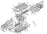
- FIG. 1is a perspective exploded view of a muffler including horizontal top and bottom outer shells, vertical first and second inner plates, an inlet tube, an outlet tube and a baffle plate;
- FIG. 2is a perspective view of the baffle plate, the vertical first and second inner plates, the inlet tube, and the outlet tube, with portions broken away, showing the vertical first and second inner plates mated together and positioned to extend through the baffle plate to form a lower tuning throat, a middle conductor tube, and an upper tuning throat, the inlet tube positioned to extend through the baffle plate, and the outlet tube positioned to extend through the baffle plate so that the vertical first and second inner plates, the baffle, the inlet tube, and the outlet tube cooperate to form a subassembly;
- FIG. 3is a cross-sectional view of the muffler taken along line 3 — 3 of FIG. 4 after the subassembly of FIG. 2 is positioned between the horizontal top and bottom outer shells showing the baffle plate including a central plate-receiving aperture sized and shaped to receive the vertical first and second inner plates therein after the plates are mated together, an inlet tube-receiving aperture to the right of the central plate-receiving aperture sized to receive the inlet tube, and an outlet tube-receiving aperture to the left of the central plate-receiving aperture sized to receive the outlet tube;
- FIG. 4is a top plan view of the muffler of FIG. 3, with portions of the top outer shell, inlet tube, and outlet tube broken away, showing the top and bottom outer shells cooperating to define a chamber, the vertical first and second inner plates cooperating with the baffle plate to partition the chamber into first, second, third, and fourth subchambers so that the inlet tube receives exhaust gases generated by an engine, communicates the exhaust gas through the lower-left first subchamber, and “dumps” the exhaust gas into the lower-right second subchambers the middle conductor defined by the vertical first and second inner plates communicates the exhaust gases “diagonally” from the second subchamber to the upper-left third subchamber, and the outlet tube communicates the exhaust gases through the upper-right fourth subchamber into the remainder of the exhaust system including a tailpipe;
- FIG. 5is a transverse sectional view of the muffler of FIG. 1 taken along lines 5 — 5 of FIG. 2 and after the installation of the subassembly of FIG. 2 in the chamber defined by the top and bottom outer shells showing the upper tuning throat defined by the vertical first and second inner plates including a first open end communicating with the upper-left third subchamber and a second open end communicating with the upper-right fourth subchamber to permit communication of noise between the third and fourth subchambers so that the fourth subchamber acts as a Helmholtz tuning subchamber;
- FIG. 6is a transverse sectional view of the muffler similar to FIG. 5, taken along lines 6 — 6 of FIG. 2, showing the middle conductor tube defined by the vertical first and second plates including a first opening communicating with the second subchamber and a second opening communicating with the third subchamber so that exhaust gases flow diagonally from the second subchamber to the third subchamber and the second and third subchambers act as first and second transfer subchambers and the middle conductor acts as a conduit therebetween; and
- FIG. 7is a transverse sectional view of the muffler, taken along lines 7 — 7 of FIG. 2, showing the lower tuning throat defined by the vertical first and second inner plates including a first opening communicating with the second subchamber and a second opening communicating with the first subchamber to permit communication of noise between the second and first subchambers so that the first subchamber acts as a Helmholtz tuning subchamber.
- FIG. 1A stamp-formed muffler 10 according to the present invention is shown in FIG. 1 .
- Muffler 10includes a stamped top outer shell 12 , a stamped bottom outer shell 14 , a stamped vertical first inner plate 16 , a stamped vertical second inner plate 18 , a vertical baffle plate 20 , an inlet tube 22 , and an outlet tube 24 as shown in FIG. 1 .
- first and second inner plates 16 , 18 , inlet tube 22 , and outlet tube 24are positioned to extend through baffle plate 20 to form a subassembly 31 as shown in FIG. 2 .
- Top and bottom outer shells 12 , 14define a chamber 33 .
- Subassembly 31is positioned between top and bottom outer shells 12 , 14 and partitions chamber 33 into first, second, third, and fourth subchambers 35 , 37 , 39 , 41 .
- muffler 10is installed in a vehicle (not shown) as part of an exhaust system 43 as shown diagrammatically in FIG. 4 .
- An engine 29generates exhaust gas that flows through exhaust system 43 and into inlet tube 22 of muffler 10 .
- Inlet tube 22communicates exhaust gas through first subchamber 35 into second subchamber 37 .
- First and second vertical inner plates 16 , 18cooperate to define a middle conductor tube 45 that communicates the exhaust gas “diagonally” across muffler 10 from second subchamber 37 to third subchamber 39 .
- Outlet tube 24then communicates the exhaust gas from third subchamber 39 through fourth subchamber 41 into the remainder of exhaust system 43 including a tail pipe 27 where the exhaust gas is dissipated in the atmosphere.
- Muffler 10is assembled by placing first and second inner plates 16 , 18 together, inserting first and second inner plates 16 , 18 through a plate-receiving aperture 26 formed in baffle plate 20 , and inserting inlet and outlet tubes 22 , 24 through respective inlet and outlet tube-receiving apertures 28 , 30 formed in baffle plate 20 to create subassembly 31 as shown in FIG. 2 .
- Top and bottom shells 12 , 14cooperate to accept subassembly 31 therebetween and top and bottom shells 12 , 14 are welded or otherwise mechanically fastened together to define muffler 10 .
- top and bottom shells 12 , 14When top and bottom shells 12 , 14 are mated together, they define chamber 33 and secure baffle plate 20 , first and second inner plates 16 , 18 , and inlet and outlet tubes 22 , 24 between top and bottom shells 12 , 14 as shown in FIGS. 3-7.
- Top shell 12is shaped to include various contours and edges as shown, for example, in FIG. 1 .
- Top shell 12includes a top wall 32 , first and second end walls 34 , 36 , first and second side walls 38 , 40 extending between first and second end walls 34 , 36 , and a flange 42 appended to side walls 38 , 40 and end walls 34 , 36 as shown in FIG. 1 .
- First and second end walls 34 , 36 and first and second side walls 38 , 40are appended to top wall 32 and extend from top wall 32 to flange 42 at a perimeter edge 46 as shown in FIG. 1 .
- Top wall 32 , first and second end walls 34 , 36 , and first and second side walls 38 , 40are formed to include stiffening ribs 44 .
- First end wall 34is formed to include an inlet passageway 48 and second end wall 36 is formed to include an outlet passageway 50 as shown in FIGS. 1 and 4.
- bottom shell 14is formed to include various contours and edges as shown, for example, in FIG. 1 .
- Bottom shell 14includes a bottom wall 52 , first and second end walls 54 , 56 , first and second side walls 58 , 60 extending between first and second end walls 54 , 56 , and a flange 62 appended to end walls 54 , 56 , and side walls 58 , 60 .
- First and second end walls 54 , 56 and first and second side walls 58 , 60are appended to bottom wall 52 and extend from bottom wall 59 to flange 62 at a perimeter edge 66 as shown, for example, in FIG. 1 .
- Bottom wall 52 , first and second end walls 54 , 56 , and first and second side walls 58 , 60are formed to include stiffening ribs 64 .
- ribs 64raise the resonant frequency of the bottom shell 14 which reduces the vibration of and noise created by bottom shell 14 .
- First end wall 54is formed to include an inlet passageway 68 and second end wall 56 is formed to include an outlet passageway 70 as shown in FIGS. 1 and 5.
- Baffle plate 20is formed to include edges and contours to interact with top and bottom shells 12 , 14 , first and second innerplates 16 , 18 , and inlet and outlet tubes 22 , 24 .
- Baffle plate 20includes a base 29 , a first inner flange 74 defining plate-receiving aperture 26 , a second inner flange 71 defining inlet tube-receiving aperture 28 , a third inner flange 75 defining outlet tube-receiving aperture 30 , and an outer flange 76 at a perimeter edge 78 as shown, for example, in FIGS. 1 and 3.
- First and second inner plates 16 , 18extend through plate-receiving aperture 26 as shown, for example, in FIG. 2 .
- First and second inner plates 16 , 18are secured to baffle plate 20 by a press-fit with first inner flange 74 .
- Outer flange 76 of baffle plate 20engages top and bottom shells 12 , 14 as shown in FIGS. 5-7. More specifically, outer flange 76 is positioned to lie in a groove 80 defined by ribs 44 , 64 of top and bottom shells 12 , 14 as shown, for example, in FIGS. 5-7.
- the outer flange of the baffle platemay be welded or otherwise coupled to the top and bottom shells.
- the outer flange of the baffle plateis not nested in grooves but “free-floats” between the top and bottom shells.
- baffle plate 20cooperates with first and second inner plates 16 , 18 to divide plate-receiving chamber 33 into first, second, third, and fourth subchambers 35 , 37 , 39 , 41 as shown, for example, in FIG. 4 .
- Subchambers 35 , 37 , 39 , 41are created without a drawing process being performed on either top wall 32 or bottom wall 52 of top and bottom shells 12 , 14 , respectively.
- Top and bottom walls 32 , 52are referred to as creaseless top and bottom walls 32 , 52 because no drawing processes are performed on creaseless top and bottom walls 32 , 52 to form subcharnbers 35 , 37 , 39 , 41 .
- Stiffening ribs 44 , 64 formed on top and bottom walls 32 , 52serve the limited purpose of reducing the vibration of and noise created by top and bottom shells 12 , 14 and do not define subchambers between top and bottom shells 12 , 14 .
- Inlet tube 22includes a first end 122 , a second end 124 spaced apart from first end 122 , and a plurality of perforations 126 .
- outlet tube 24includes a first end 128 , a second end 130 spaced apart from first end 128 , and a plurality of perforations 132 .
- Inlet and outlet tubes 22 , 24extend through respective inlet and outlet tube-receiving apertures 28 , 30 of baffle plate 20 as shown in FIG. 2 .
- Inlet and outlet tubes 22 , 24are then secured to baffle plate 20 by a press-fit with respective second and third inner flanges 71 , 75 .
- first end 122 of inlet tube 22is positioned to lie between inlet passageways 48 , 68 of top and bottom shells 12 , 14 .
- second end 130 of outlet tube 24is positioned to lie between outlet passageways 50 , 70 of top and bottom shells 12 , 14 .
- First and second inner plates 16 , 18are stamped from a sheet of stainless steel in the shape as shown in FIGS. 1 and 3.
- the components of the mufflermay be stamped from sheets of cold-rolled, stainless steel, aluminized stainless steel, and any other appropriate type of material.
- First inner plate 16includes a base 90 having an outer periphery 91 , a first channel 92 , a second channel 94 , and a third channel 96 as shown, for example, in FIG. 1 .
- Second inner plate 18is similar to first inner plate 16 and includes a base 98 having an outer periphery 99 , a first channel 110 , a second channel 112 , and a third channel 114 as shown, for example, in FIG. 1 .
- Outer peripheries 91 , 99are positioned to lie in a groove 81 defined by ribs 44 , 64 of top and bottom shells 12 , 14 as shown, for example, in FIGS. 5-7.
- the first and second inner platesinclude outer flanges (not shown) coupled to the outer peripheries of respective bases and positioned in groove 81 .
- first and second inner plates 16 , 18are positioned in plate-receiving aperture 26 of baffle plate 20 , a plane defined by bases 90 , 98 of first and second inner plates 16 , 18 is substantially perpendicular to a plane defined by base 21 of baffle plate 20 as shown in FIG. 4 .
- the plane defined by base 21 of baffle plate 20is substantially perpendicular to top wall 32 of top outer shell 12 and bottom wall 52 of bottom outer shell 14 and the plane defined by bases 90 , 98 of first and second inner plates 16 , 18 is substantially perpendicular to top wall 32 of top outer shell 12 and bottom wall 52 of bottom outer shell 14 .
- inlet and outlet tubes 22 , 158are substantially parallel to top wall 32 and bottom wall 52 , substantially perpendicular to the plane defined by base 21 of baffle plate 20 , and substantially parallel to and spaced apart from the plane defined by bases 90 , 98 of first and second inner plates 16 , 18 .
- first and second inner plates 16 , 18 , and outlet tube 24cooperate to form a path for exhaust gas to flow through muffler 10 .
- first channels 92 , 110cooperate to define a lower first tuning throat 116 as shown in FIG. 7
- second channels 94 , 112cooperate to define a middle tube 118 as shown in FIG. 6,
- third channels 96 , 114combine to define an upper second tuning throat 120 as shown in FIG. 5 .
- first and second inner plates 16 , 18are connected together by seam welding between and along the length of the respective cooperating channels 92 , 110 ; 94 , 112 ; and 96 , 114 . As shown in FIG.
- inlet tube 22 , outlet tube 158 , and middle tube 118are coplanar in a horizontal plane defined therethrough and spaced apart from bottom wall 52 of bottom outer shell 14 by a substantially equal vertical distance.
- First tuning throat 116is vertically lower than the plane defined by inlet tube 22 , outlet tube 158 , and middle tube 118 .
- second tuning throat 120is vertically higher than the plane defined by inlet tube 22 , outlet tube 158 , and middle tube 118 .
- Exhaust gasflows from first end 122 of inlet tube 22 to second end 130 of outlet tube 24 along a serpentine path 53 through inlet tube 22 , tube 118 of vertical first and second inner plates 16 , 18 , and outlet tube 24 as best shown in FIGS. 4 and 6.
- Inlet tube 22is formed to permit communication of exhaust gas from exhaust system 43 to second subchamber 37 .
- Second end 124 of inlet tube 22is formed to include an opening 134 that communicates with second subchamber 37 .
- Middle tube 118 of inner plates 16 , 18is formed to permit communication of exhaust gas from second subchamber 37 to third subchamber 39 .
- Tube 118includes a first end 138 positioned to lie adjacent to second end walls 36 , 56 of top and bottom shells 12 , 14 and a second end 140 positioned to lie adjacent to first end walls 34 , 54 of top and bottom shells 12 , 14 as shown, for example, in FIG. 5 .
- second channel 94 of first inner plate 16is formed to include an open end 142 that defines an opening 144 through which exhaust gas travels between second subchamber 37 and tube 118 .
- second channel 112 of second inner plate 18is formed to include an open end 146 that defines an opening 148 through which exhaust gas travels between tube 118 and third subchamber 39 .
- second channel 112 of second inner plate 18is formed to include a closed end 141 that prevents gas from passing into fourth subchamber 41 from tube 118 .
- second channel 94 of first inner plate 16is formed to include a closed end 145 that prevents gas from passing into first subchamber 35 from tube 118 .
- Outlet tube 158is formed to permit communication of exhaust gases from muffler 10 to the remainder of exhaust system 43 including tail pipe 27 as shown in FIG. 4 .
- First end 128 of outlet tube 24is formed to include an opening 136 that communicates with third subchamber 39 as shown in FIG. 5 . Exhaust gas enters outlet tube 158 through opening 136 then exists muffler 10 through second end 130 to the remainder of exhaust system 43 .
- First tuning throat 116is formed to permit communication of noise from second subchamber 37 to first subchamber 82 as shown in FIG. 7 .
- First tuning throat 116includes a first end 150 positioned to lie adjacent to second end walls 36 , 56 of top and bottom shells 12 , 14 and a second end 152 positioned to lie adjacent to first end walls 34 , 54 of top and bottom shells 12 , 14 .
- first channel 92 of first inner plate 16is formed to include an open end 154 that defines an opening 156 through which noise enters first tuning throat 116 from second subchamber 37 as shown in FIG. 7 .
- first channel 92 of first inner plate 16is formed to include an open end 158 defining an opening 160 through which noise that entered first tuning throat 116 exits into first subchamber 35 .
- first channel 110 of second inner plate 18is formed to include a closed end 153 that prevents gas from entering fourth subchamber 41 from first tuning throat 116 .
- first channel 110 of second inner plate 18is formed to include a closed end 157 that prevents gas from entering third subchamber 39 from tuning throat 116 .
- first tuning throat 116allows low frequency noise to pass from second subchamber 37 into first subchamber 35 so that first subchamber 35 acts as a first Helmholtz tuning subchamber 159 for the attenuation of such low frequency noise.
- Second tuning throat 120is formed to permit communication of noise from third subchamber 39 to fourth subchamber 41 as shown in FIG. 5 .
- Second tuning throat 120includes a first end 162 positioned to lie adjacent to first end walls 34 , 54 of top and bottom shells 12 , 14 and a second end 164 positioned to lie adjacent to second end walls 36 , 56 of top and bottom shells 12 , 14 .
- third channel 114 of second inner plate 18is formed to include an open end 166 that defines an opening 168 through which noise enters second tuning throat 120 from third subchamber 39 .
- third channel 114 of second inner plate 18is formed to include an open end 170 defining an opening 172 through which noise that entered second tuning throat 120 exits into fourth subchamber 41 .
- third channel 96 of first inner plate 16is formed to include a closed end 165 that prevents gas from entering first subchamber 35 from second tuning throat 120 .
- third channel 96 of first inner plate 16is formed to include a closed end 169 that prevents gas from entering second subchamber 37 from second tuning throat 120 .
- second tuning throat 120allows low frequency noise to pass from third subchamber 39 into fourth subchamber 41 so that fourth subchamber 41 acts as a second Helmholtz tuning subchamber 161 for the attenuation of such low frequency noise.
- First and second tuning throats 116 , 120having respective lengths 117 , 121 and inside diameters 119 , 123 as shown in FIGS. 7 and 4.
- Lengths 117 , 121 and inside diameters 119 , 123are selected to attenuate a specific range of frequencies.
- Length 117 and inside diameter 119 of first tuning throat 116may be the same or different than respective length 121 and diameter 123 of second tuning throat 120 .
- Exhaust gastravels through muffler 10 along serpentine path 53 until it exits muffler 10 .
- Exhaust gasenters muffler 10 through first end 122 of inlet tube 22 in direction 174 as shown in FIG. 5 .
- Exhaust gasflows through inlet tube 22 and exits inlet tube 22 in direction 176 through opening 134 into second subchamber 37 .
- Inlet tube 22is formed to include perforations 126 through which exhaust gas in inlet tube 22 also communicates with second subchamber 37 . Perforations attenuate high frequency noise and aid in “tuning” the muffler.
- first tuning throat 116permits exhaust gas to communicate between second subchamber 37 and first subchamber 35 .
- Exhaust gascontinues flowing in direction 180 from second subchamber 37 through opening 144 of tube 118 as shown in FIG. 5 .
- Exhaust gasflows diagonally through middle tube 118 and exits tube 118 in direction 182 through opening 168 into third subchamber 34 as shown in FIG. 5.
- a portion of tube 118 lying in second subchamber 84is formed to include a plurality of perforations 186 through which exhaust gas in inlet tube 22 communicates with second subchamber 37 .
- a portion of tube 118 lying in third subchamber 88is formed to include perforations 178 through which exhaust gas also communicates with third subchamber 39 .
- Outlet tube 24is formed to include perforations 132 through which exhaust gas in outlet tube 24 communicates with third subchamber 39 .
- second tuning throat 120permits exhaust gas to communicate between third subchamber 39 and fourth subchamber 41 .
- Exhaust gasthen exits muffler 10 in direction 190 through second end 130 of outlet tube 24 as shown in FIG. 5 into the remainder of exhaust system 43 .
- the inlet tube, outlet tube, and the tubemay be formed to include louvers (not shown) instead of perforations.
Landscapes
- Engineering & Computer Science (AREA)
- Chemical & Material Sciences (AREA)
- Combustion & Propulsion (AREA)
- Mechanical Engineering (AREA)
- General Engineering & Computer Science (AREA)
- Exhaust Silencers (AREA)
Abstract
Description
Claims (28)
Priority Applications (1)
| Application Number | Priority Date | Filing Date | Title |
|---|---|---|---|
| US09/914,905US6659222B1 (en) | 1999-03-05 | 2000-03-03 | Multi-chambered muffler |
Applications Claiming Priority (3)
| Application Number | Priority Date | Filing Date | Title |
|---|---|---|---|
| US12288199P | 1999-03-05 | 1999-03-05 | |
| US09/914,905US6659222B1 (en) | 1999-03-05 | 2000-03-03 | Multi-chambered muffler |
| PCT/US2000/005673WO2000052312A1 (en) | 1999-03-05 | 2000-03-03 | Multi-chambered muffler |
Publications (1)
| Publication Number | Publication Date |
|---|---|
| US6659222B1true US6659222B1 (en) | 2003-12-09 |
Family
ID=22405388
Family Applications (1)
| Application Number | Title | Priority Date | Filing Date |
|---|---|---|---|
| US09/914,905Expired - Fee RelatedUS6659222B1 (en) | 1999-03-05 | 2000-03-03 | Multi-chambered muffler |
Country Status (3)
| Country | Link |
|---|---|
| US (1) | US6659222B1 (en) |
| EP (1) | EP1157199A4 (en) |
| WO (1) | WO2000052312A1 (en) |
Cited By (13)
| Publication number | Priority date | Publication date | Assignee | Title |
|---|---|---|---|---|
| US20050155817A1 (en)* | 2004-01-17 | 2005-07-21 | Jan Brand | Muffler for internal combustion motor vehicles |
| US7108646B1 (en)* | 2002-11-12 | 2006-09-19 | Quick Catherine G | Infant roll cushion and method |
| US20070062757A1 (en)* | 2005-09-21 | 2007-03-22 | Arvin Technologies, Inc. | Pressed assembly for passive valve installation |
| US20090188747A1 (en)* | 2008-01-28 | 2009-07-30 | Benteler Automobiltechnik Gmbh | Method of making an exhaust-noise attenuation muffler, and exhaust-noise attenuation muffler |
| US20100193282A1 (en)* | 2009-01-30 | 2010-08-05 | Geon-Seok Kim | Broadband noise resonator |
| US20100247945A1 (en)* | 2009-03-30 | 2010-09-30 | Gm Global Technology Operations, Inc. | Sheet Metal Panel Shape for Low Sound Radiation |
| US20100307865A1 (en)* | 2009-06-08 | 2010-12-09 | Olsen Douglas M | Silencer for internal combustion engine |
| US20140096856A1 (en)* | 2012-10-04 | 2014-04-10 | Friedrich Boysen Gmbh & Co. Kg | Exhaust gas system component for internal combustion engine and method of manufacturing an exhaust gas system component |
| US9163547B2 (en)* | 2012-06-13 | 2015-10-20 | Eberspächer Exhaust Technology GmbH & Co. KG | Lightweight construction silencer |
| US20170159520A1 (en)* | 2015-12-07 | 2017-06-08 | Eberspächer Exhaust Technology GmbH & Co. KG | Muffler and method for manufacturing same |
| US9677455B2 (en) | 2014-07-17 | 2017-06-13 | Big Rapids Products, Inc. | Stackable muffler shell |
| DE102013223992B4 (en) | 2012-12-07 | 2022-03-03 | Hanon Systems | Universal damping device for an air conditioning circuit |
| EP4112892A1 (en)* | 2021-06-30 | 2023-01-04 | Purem GmbH | Sound absorber |
Citations (12)
| Publication number | Priority date | Publication date | Assignee | Title |
|---|---|---|---|---|
| US3125182A (en)* | 1964-03-17 | earley | ||
| US4164266A (en) | 1976-08-19 | 1979-08-14 | Lars Collin | Exhaust gas muffler |
| US4700806A (en) | 1986-11-25 | 1987-10-20 | Ap Industries, Inc. | Stamp formed muffler |
| US4941545A (en) | 1989-04-28 | 1990-07-17 | Arvin Industries, Inc. | Muffler assembly |
| US5012891A (en)* | 1989-02-15 | 1991-05-07 | Tennessee Gas Pipeline Company | Muffler assembly |
| US5229557A (en) | 1991-05-28 | 1993-07-20 | Arvin Industries, Inc. | Rigidified muffler assembly |
| US5597986A (en)* | 1995-02-27 | 1997-01-28 | Ap Parts Manufacturing Company | Stamp formed muffler with nested chambers |
| US5816361A (en)* | 1994-03-02 | 1998-10-06 | Ap Parts Manufacturing Company | Exhaust mufflers with stamp formed internal components and method of manufacture |
| US5859394A (en)* | 1997-06-12 | 1999-01-12 | Ap Parts Manufacturing Company | Muffler with stamped internal plates defining tubes and separating chambers |
| US6135237A (en)* | 1998-04-03 | 2000-10-24 | Arvin Industries, Inc. | Stamp-formed muffler |
| US6164412A (en)* | 1998-04-03 | 2000-12-26 | Arvin Industries, Inc. | Muffler |
| US6341664B1 (en)* | 2000-01-13 | 2002-01-29 | Goerlich's Inc. | Exhaust muffler with stamp formed internal assembly |
Family Cites Families (2)
| Publication number | Priority date | Publication date | Assignee | Title |
|---|---|---|---|---|
| US4759423A (en)* | 1987-06-11 | 1988-07-26 | Ap Industries, Inc. | Tube and chamber construction for an exhaust muffler |
| US5949035A (en)* | 1997-03-24 | 1999-09-07 | Arvin Industries, Inc. | Stamp-formed muffler having a unitary inner cartridge |
- 2000
- 2000-03-03EPEP00919358Apatent/EP1157199A4/ennot_activeWithdrawn
- 2000-03-03WOPCT/US2000/005673patent/WO2000052312A1/ennot_activeApplication Discontinuation
- 2000-03-03USUS09/914,905patent/US6659222B1/ennot_activeExpired - Fee Related
Patent Citations (13)
| Publication number | Priority date | Publication date | Assignee | Title |
|---|---|---|---|---|
| US3125182A (en)* | 1964-03-17 | earley | ||
| US4164266A (en) | 1976-08-19 | 1979-08-14 | Lars Collin | Exhaust gas muffler |
| US4700806A (en) | 1986-11-25 | 1987-10-20 | Ap Industries, Inc. | Stamp formed muffler |
| US5012891A (en)* | 1989-02-15 | 1991-05-07 | Tennessee Gas Pipeline Company | Muffler assembly |
| US4941545A (en) | 1989-04-28 | 1990-07-17 | Arvin Industries, Inc. | Muffler assembly |
| US5147987A (en) | 1989-04-28 | 1992-09-15 | Arvin Industries, Inc. | Muffler assembly |
| US5229557A (en) | 1991-05-28 | 1993-07-20 | Arvin Industries, Inc. | Rigidified muffler assembly |
| US5816361A (en)* | 1994-03-02 | 1998-10-06 | Ap Parts Manufacturing Company | Exhaust mufflers with stamp formed internal components and method of manufacture |
| US5597986A (en)* | 1995-02-27 | 1997-01-28 | Ap Parts Manufacturing Company | Stamp formed muffler with nested chambers |
| US5859394A (en)* | 1997-06-12 | 1999-01-12 | Ap Parts Manufacturing Company | Muffler with stamped internal plates defining tubes and separating chambers |
| US6135237A (en)* | 1998-04-03 | 2000-10-24 | Arvin Industries, Inc. | Stamp-formed muffler |
| US6164412A (en)* | 1998-04-03 | 2000-12-26 | Arvin Industries, Inc. | Muffler |
| US6341664B1 (en)* | 2000-01-13 | 2002-01-29 | Goerlich's Inc. | Exhaust muffler with stamp formed internal assembly |
Cited By (20)
| Publication number | Priority date | Publication date | Assignee | Title |
|---|---|---|---|---|
| US7108646B1 (en)* | 2002-11-12 | 2006-09-19 | Quick Catherine G | Infant roll cushion and method |
| US20050155817A1 (en)* | 2004-01-17 | 2005-07-21 | Jan Brand | Muffler for internal combustion motor vehicles |
| US20070062757A1 (en)* | 2005-09-21 | 2007-03-22 | Arvin Technologies, Inc. | Pressed assembly for passive valve installation |
| US7575096B2 (en)* | 2005-09-21 | 2009-08-18 | Emcon Technologies Llc | Pressed assembly for passive valve installation |
| US20090188747A1 (en)* | 2008-01-28 | 2009-07-30 | Benteler Automobiltechnik Gmbh | Method of making an exhaust-noise attenuation muffler, and exhaust-noise attenuation muffler |
| US7926615B2 (en)* | 2008-01-28 | 2011-04-19 | Benteler Automobiltechnik Gmbh | Method of making an exhaust-noise attenuation muffler, and exhaust-noise attenuation muffler |
| US7934581B2 (en)* | 2009-01-30 | 2011-05-03 | Eaton Corporation | Broadband noise resonator |
| US20100193282A1 (en)* | 2009-01-30 | 2010-08-05 | Geon-Seok Kim | Broadband noise resonator |
| US20100247945A1 (en)* | 2009-03-30 | 2010-09-30 | Gm Global Technology Operations, Inc. | Sheet Metal Panel Shape for Low Sound Radiation |
| US7942240B2 (en) | 2009-06-08 | 2011-05-17 | Honda Motor Co., Ltd. | Silencer for internal combustion engine |
| US20100307865A1 (en)* | 2009-06-08 | 2010-12-09 | Olsen Douglas M | Silencer for internal combustion engine |
| US9163547B2 (en)* | 2012-06-13 | 2015-10-20 | Eberspächer Exhaust Technology GmbH & Co. KG | Lightweight construction silencer |
| US20140096856A1 (en)* | 2012-10-04 | 2014-04-10 | Friedrich Boysen Gmbh & Co. Kg | Exhaust gas system component for internal combustion engine and method of manufacturing an exhaust gas system component |
| US9133962B2 (en)* | 2012-10-04 | 2015-09-15 | Friedrich Boysen Gmbh & Co. Kg | Exhaust gas system component for internal combustion engine and method of manufacturing an exhaust gas system component |
| DE102013223992B4 (en) | 2012-12-07 | 2022-03-03 | Hanon Systems | Universal damping device for an air conditioning circuit |
| US9677455B2 (en) | 2014-07-17 | 2017-06-13 | Big Rapids Products, Inc. | Stackable muffler shell |
| US20170159520A1 (en)* | 2015-12-07 | 2017-06-08 | Eberspächer Exhaust Technology GmbH & Co. KG | Muffler and method for manufacturing same |
| US10174654B2 (en)* | 2015-12-07 | 2019-01-08 | Eberspächer Exhaust Technology GmbH & Co. KG | Muffler and method for manufacturing same |
| EP4112892A1 (en)* | 2021-06-30 | 2023-01-04 | Purem GmbH | Sound absorber |
| US12104512B2 (en) | 2021-06-30 | 2024-10-01 | Purem GmbH | Muffler and method for making the same |
Also Published As
| Publication number | Publication date |
|---|---|
| EP1157199A4 (en) | 2002-05-29 |
| WO2000052312A9 (en) | 2002-07-11 |
| WO2000052312A1 (en) | 2000-09-08 |
| EP1157199A1 (en) | 2001-11-28 |
Similar Documents
| Publication | Publication Date | Title |
|---|---|---|
| US6164412A (en) | Muffler | |
| US4700806A (en) | Stamp formed muffler | |
| US6659222B1 (en) | Multi-chambered muffler | |
| EP0564692B1 (en) | Stamp formed muffler with inline expansion chamber and arcuately formed effective flow tubes | |
| US5147987A (en) | Muffler assembly | |
| US5173577A (en) | Stamp formed muffler with low back pressure | |
| US4736817A (en) | Stamp formed muffler | |
| US4760894A (en) | Exhaust muffler with angularly aligned inlets and outlets | |
| US5597986A (en) | Stamp formed muffler with nested chambers | |
| US5448831A (en) | Method of manufacturing a stamp formed muffler with hermetically sealed laminated outer shell | |
| US6135237A (en) | Stamp-formed muffler | |
| US4953660A (en) | Muffler with two part housing and flow tubes | |
| US6415889B1 (en) | Stamped-formed muffler apparatus and assembly process | |
| US6457553B1 (en) | Low cost muffler | |
| US6257367B1 (en) | Stamp-formed muffler | |
| US5949035A (en) | Stamp-formed muffler having a unitary inner cartridge | |
| US5473891A (en) | Three-piece stamp formed connector for achieving equal length exhaust pipes | |
| US5428194A (en) | Narrow width stamp formed muffler | |
| US6199659B1 (en) | Stamp-formed muffler | |
| EP0856647B1 (en) | Muffler with stamped internal plates defining tubes and separating chambers | |
| US20240035405A1 (en) | Exhaust sound attenuation and control system | |
| US12305546B2 (en) | Exhaust sound attenuation and control system | |
| US3513939A (en) | Exhaust gas muffler | |
| CA2045700C (en) | Muffler assembly | |
| JP2025142752A (en) | silencer |
Legal Events
| Date | Code | Title | Description |
|---|---|---|---|
| AS | Assignment | Owner name:ARVINMERITOR, INC., MICHIGAN Free format text:MERGER;ASSIGNOR:ARVIN INDUSTRIES, INC.;REEL/FRAME:011328/0300 Effective date:20000707 | |
| AS | Assignment | Owner name:ARVINMERITOR, INC., MICHIGAN Free format text:ASSIGNMENT OF ASSIGNORS INTEREST;ASSIGNOR:ALLMAN, JAMES R.;REEL/FRAME:012217/0137 Effective date:20010910 | |
| AS | Assignment | Owner name:JPMORGAN CHASE BANK, NATIONAL ASSOCIATION, FOR ITS Free format text:SECURITY AGREEMENT;ASSIGNOR:ARVINMERITOR, INC.;REEL/FRAME:018184/0356 Effective date:20060823 | |
| AS | Assignment | Owner name:ARVINMERITOR, INC., MICHIGAN Free format text:PARTIAL RELEASE OF PATENT SECURITY INTEREST;ASSIGNOR:JPMORGAN CHASE BANK, NATIONAL ASSOCIATION;REEL/FRAME:019341/0492 Effective date:20070516 | |
| AS | Assignment | Owner name:ET US HOLDINGS LLC, DELAWARE Free format text:ASSIGNMENT OF ASSIGNORS INTEREST;ASSIGNOR:ARVINMERITOR, INC.;REEL/FRAME:019379/0277 Effective date:20070516 | |
| AS | Assignment | Owner name:THE CIT GROUP/BUSINESS CREDIT, INC.,ILLINOIS Free format text:SECURITY AGREEMENT;ASSIGNOR:ET US HOLDINGS LLC;REEL/FRAME:019353/0736 Effective date:20070525 Owner name:THE CIT GROUP/BUSINESS CREDIT, INC., ILLINOIS Free format text:SECURITY AGREEMENT;ASSIGNOR:ET US HOLDINGS LLC;REEL/FRAME:019353/0736 Effective date:20070525 | |
| REMI | Maintenance fee reminder mailed | ||
| LAPS | Lapse for failure to pay maintenance fees | ||
| STCH | Information on status: patent discontinuation | Free format text:PATENT EXPIRED DUE TO NONPAYMENT OF MAINTENANCE FEES UNDER 37 CFR 1.362 | |
| FP | Lapsed due to failure to pay maintenance fee | Effective date:20071209 | |
| AS | Assignment | Owner name:EMCON TECHNOLOGIES LLC (FORMERLY KNOWN AS ET US HO Free format text:RELEASE BY SECURED PARTY;ASSIGNOR:CIT GROUP/BUSINESS CREDIT, INC.;REEL/FRAME:023957/0741 Effective date:20100208 | |
| AS | Assignment | Owner name:AXLETECH INTERNATIONAL IP HOLDINGS, LLC, MICHIGAN Free format text:RELEASE BY SECURED PARTY;ASSIGNOR:JPMORGAN CHASE BANK, N.A., AS ADMINISTRATIVE AGENT;REEL/FRAME:061521/0550 Effective date:20220803 Owner name:MERITOR TECHNOLOGY, LLC, MICHIGAN Free format text:RELEASE BY SECURED PARTY;ASSIGNOR:JPMORGAN CHASE BANK, N.A., AS ADMINISTRATIVE AGENT;REEL/FRAME:061521/0550 Effective date:20220803 Owner name:MOTOR HEAVY VEHICLE SYSTEMS, LLC, MICHIGAN Free format text:RELEASE BY SECURED PARTY;ASSIGNOR:JPMORGAN CHASE BANK, N.A., AS ADMINISTRATIVE AGENT;REEL/FRAME:061521/0550 Effective date:20220803 Owner name:ARVINMERITOR OE, LLC, MICHIGAN Free format text:RELEASE BY SECURED PARTY;ASSIGNOR:JPMORGAN CHASE BANK, N.A., AS ADMINISTRATIVE AGENT;REEL/FRAME:061521/0550 Effective date:20220803 Owner name:MERITOR HEAVY VEHICLE SYSTEMS, LLC, MICHIGAN Free format text:RELEASE BY SECURED PARTY;ASSIGNOR:JPMORGAN CHASE BANK, N.A., AS ADMINISTRATIVE AGENT;REEL/FRAME:061521/0550 Effective date:20220803 Owner name:ARVINMERITOR TECHNOLOGY, LLC, MICHIGAN Free format text:RELEASE BY SECURED PARTY;ASSIGNOR:JPMORGAN CHASE BANK, N.A., AS ADMINISTRATIVE AGENT;REEL/FRAME:061521/0550 Effective date:20220803 Owner name:MAREMOUNT CORPORATION, MICHIGAN Free format text:RELEASE BY SECURED PARTY;ASSIGNOR:JPMORGAN CHASE BANK, N.A., AS ADMINISTRATIVE AGENT;REEL/FRAME:061521/0550 Effective date:20220803 Owner name:EUCLID INDUSTRIES, LLC, MICHIGAN Free format text:RELEASE BY SECURED PARTY;ASSIGNOR:JPMORGAN CHASE BANK, N.A., AS ADMINISTRATIVE AGENT;REEL/FRAME:061521/0550 Effective date:20220803 Owner name:GABRIEL RIDE CONTROL PRODUCTS, INC., MICHIGAN Free format text:RELEASE BY SECURED PARTY;ASSIGNOR:JPMORGAN CHASE BANK, N.A., AS ADMINISTRATIVE AGENT;REEL/FRAME:061521/0550 Effective date:20220803 Owner name:ARVIN TECHNOLOGIES, INC., MICHIGAN Free format text:RELEASE BY SECURED PARTY;ASSIGNOR:JPMORGAN CHASE BANK, N.A., AS ADMINISTRATIVE AGENT;REEL/FRAME:061521/0550 Effective date:20220803 Owner name:MERITOR TRANSMISSION CORPORATION, MICHIGAN Free format text:RELEASE BY SECURED PARTY;ASSIGNOR:JPMORGAN CHASE BANK, N.A., AS ADMINISTRATIVE AGENT;REEL/FRAME:061521/0550 Effective date:20220803 Owner name:ARVINMERITOR, INC., MICHIGAN Free format text:RELEASE BY SECURED PARTY;ASSIGNOR:JPMORGAN CHASE BANK, N.A., AS ADMINISTRATIVE AGENT;REEL/FRAME:061521/0550 Effective date:20220803 |