US6658991B2 - Barbeque grill spit assembly - Google Patents
Barbeque grill spit assemblyDownload PDFInfo
- Publication number
- US6658991B2 US6658991B2US09/759,399US75939901AUS6658991B2US 6658991 B2US6658991 B2US 6658991B2US 75939901 AUS75939901 AUS 75939901AUS 6658991 B2US6658991 B2US 6658991B2
- Authority
- US
- United States
- Prior art keywords
- spit
- rotisserie
- bracket
- brackets
- drive gear
- Prior art date
- Legal status (The legal status is an assumption and is not a legal conclusion. Google has not performed a legal analysis and makes no representation as to the accuracy of the status listed.)
- Expired - Fee Related
Links
- 235000013305foodNutrition0.000claimsdescription221
- 238000010411cookingMethods0.000claimsdescription125
- 239000011521glassSubstances0.000description59
- 238000010438heat treatmentMethods0.000description47
- 239000002184metalSubstances0.000description40
- 229910052751metalInorganic materials0.000description40
- 239000003570airSubstances0.000description31
- 238000004140cleaningMethods0.000description26
- 238000013461designMethods0.000description22
- 238000010025steamingMethods0.000description19
- 239000004519greaseSubstances0.000description17
- 238000010792warmingMethods0.000description17
- 230000008901benefitEffects0.000description16
- 239000003921oilSubstances0.000description15
- 241000287828Gallus gallusSpecies0.000description12
- 210000003811fingerAnatomy0.000description12
- 238000000034methodMethods0.000description12
- 235000013330chicken meatNutrition0.000description11
- 235000013311vegetablesNutrition0.000description10
- 238000000576coating methodMethods0.000description9
- 238000010276constructionMethods0.000description9
- 239000007788liquidSubstances0.000description8
- 239000000463materialSubstances0.000description8
- XLYOFNOQVPJJNP-UHFFFAOYSA-NwaterSubstancesOXLYOFNOQVPJJNP-UHFFFAOYSA-N0.000description8
- 230000007246mechanismEffects0.000description7
- 230000008569processEffects0.000description7
- 230000009467reductionEffects0.000description7
- 230000005540biological transmissionEffects0.000description6
- 239000011248coating agentSubstances0.000description6
- 238000003780insertionMethods0.000description6
- 230000037431insertionEffects0.000description6
- 235000013372meatNutrition0.000description6
- 230000000284resting effectEffects0.000description6
- 210000004247handAnatomy0.000description5
- 210000003128headAnatomy0.000description5
- 239000004033plasticSubstances0.000description5
- 229920003023plasticPolymers0.000description5
- 239000000779smokeSubstances0.000description5
- 230000001360synchronised effectEffects0.000description5
- 241000286209PhasianidaeSpecies0.000description4
- 238000005524ceramic coatingMethods0.000description4
- 238000001816coolingMethods0.000description4
- 235000021268hot foodNutrition0.000description3
- 238000004519manufacturing processMethods0.000description3
- 239000003381stabilizerSubstances0.000description3
- 238000013022ventingMethods0.000description3
- 238000004804windingMethods0.000description3
- 241000251468ActinopterygiiSpecies0.000description2
- 229910000831SteelInorganic materials0.000description2
- 239000000919ceramicSubstances0.000description2
- 230000008602contractionEffects0.000description2
- 239000008162cooking oilSubstances0.000description2
- 230000008878couplingEffects0.000description2
- 238000010168coupling processMethods0.000description2
- 238000005859coupling reactionMethods0.000description2
- 230000009977dual effectEffects0.000description2
- 230000005611electricityEffects0.000description2
- 239000003925fatSubstances0.000description2
- 230000004313glareEffects0.000description2
- 230000005484gravityEffects0.000description2
- 235000015090marinadesNutrition0.000description2
- 230000000149penetrating effectEffects0.000description2
- 238000002360preparation methodMethods0.000description2
- 230000000630rising effectEffects0.000description2
- 238000005096rolling processMethods0.000description2
- 238000000926separation methodMethods0.000description2
- 238000004904shorteningMethods0.000description2
- 238000009987spinningMethods0.000description2
- 239000010959steelSubstances0.000description2
- 238000003756stirringMethods0.000description2
- 210000003813thumbAnatomy0.000description2
- 210000000707wristAnatomy0.000description2
- 241000272525Anas platyrhynchosSpecies0.000description1
- 241000272517AnseriformesSpecies0.000description1
- 229920000742CottonPolymers0.000description1
- 241000238557DecapodaSpecies0.000description1
- 239000004278EU approved seasoningSubstances0.000description1
- 239000004743PolypropyleneSubstances0.000description1
- 235000002595Solanum tuberosumNutrition0.000description1
- 244000061456Solanum tuberosumSpecies0.000description1
- 235000002017Zea mays subsp maysNutrition0.000description1
- 241000482268Zea mays subsp. maysSpecies0.000description1
- 238000013019agitationMethods0.000description1
- 239000012080ambient airSubstances0.000description1
- 238000013459approachMethods0.000description1
- 230000000712assemblyEffects0.000description1
- 238000000429assemblyMethods0.000description1
- 235000015241baconNutrition0.000description1
- 239000003610charcoalSubstances0.000description1
- 230000001276controlling effectEffects0.000description1
- 238000005034decorationMethods0.000description1
- 230000007423decreaseEffects0.000description1
- 239000003599detergentSubstances0.000description1
- 238000011161developmentMethods0.000description1
- 238000004851dishwashingMethods0.000description1
- 239000006185dispersionSubstances0.000description1
- 238000009826distributionMethods0.000description1
- 230000003670easy-to-cleanEffects0.000description1
- 239000004744fabricSubstances0.000description1
- 235000011194food seasoning agentNutrition0.000description1
- 235000011389fruit/vegetable juiceNutrition0.000description1
- 230000003760hair shineEffects0.000description1
- 238000005286illuminationMethods0.000description1
- 239000000976inkSubstances0.000description1
- 230000001788irregularEffects0.000description1
- 241000238565lobsterSpecies0.000description1
- 150000002739metalsChemical class0.000description1
- 229920000515polycarbonatePolymers0.000description1
- 239000004417polycarbonateSubstances0.000description1
- -1polypropylenePolymers0.000description1
- 229920001155polypropylenePolymers0.000description1
- 229920001296polysiloxanePolymers0.000description1
- 235000012015potatoesNutrition0.000description1
- 230000002035prolonged effectEffects0.000description1
- 230000001105regulatory effectEffects0.000description1
- 235000015067saucesNutrition0.000description1
- 238000006748scratchingMethods0.000description1
- 230000002393scratching effectEffects0.000description1
- 235000014102seafoodNutrition0.000description1
- 230000035939shockEffects0.000description1
- 239000000344soapSubstances0.000description1
- 239000007787solidSubstances0.000description1
- 235000014347soupsNutrition0.000description1
- 235000013599spicesNutrition0.000description1
- 238000003860storageMethods0.000description1
- 238000012360testing methodMethods0.000description1
- 229920001187thermosetting polymerPolymers0.000description1
- 238000012546transferMethods0.000description1
- 239000002699waste materialSubstances0.000description1
Images


Classifications
- A—HUMAN NECESSITIES
- A47—FURNITURE; DOMESTIC ARTICLES OR APPLIANCES; COFFEE MILLS; SPICE MILLS; SUCTION CLEANERS IN GENERAL
- A47J—KITCHEN EQUIPMENT; COFFEE MILLS; SPICE MILLS; APPARATUS FOR MAKING BEVERAGES
- A47J37/00—Baking; Roasting; Grilling; Frying
- A47J37/06—Roasters; Grills; Sandwich grills
- A47J37/07—Roasting devices for outdoor use; Barbecues
- A—HUMAN NECESSITIES
- A47—FURNITURE; DOMESTIC ARTICLES OR APPLIANCES; COFFEE MILLS; SPICE MILLS; SUCTION CLEANERS IN GENERAL
- A47J—KITCHEN EQUIPMENT; COFFEE MILLS; SPICE MILLS; APPARATUS FOR MAKING BEVERAGES
- A47J37/00—Baking; Roasting; Grilling; Frying
- A47J37/06—Roasters; Grills; Sandwich grills
- A47J37/0623—Small-size cooking ovens, i.e. defining an at least partially closed cooking cavity
- A47J37/0629—Small-size cooking ovens, i.e. defining an at least partially closed cooking cavity with electric heating elements
- A47J37/0635—Small-size cooking ovens, i.e. defining an at least partially closed cooking cavity with electric heating elements with reflectors
- A—HUMAN NECESSITIES
- A47—FURNITURE; DOMESTIC ARTICLES OR APPLIANCES; COFFEE MILLS; SPICE MILLS; SUCTION CLEANERS IN GENERAL
- A47J—KITCHEN EQUIPMENT; COFFEE MILLS; SPICE MILLS; APPARATUS FOR MAKING BEVERAGES
- A47J37/00—Baking; Roasting; Grilling; Frying
- A47J37/04—Roasting apparatus with movably-mounted food supports or with movable heating implements; Spits
- A47J37/041—Roasting apparatus with movably-mounted food supports or with movable heating implements; Spits with food supports rotating about a horizontal axis
- A—HUMAN NECESSITIES
- A47—FURNITURE; DOMESTIC ARTICLES OR APPLIANCES; COFFEE MILLS; SPICE MILLS; SUCTION CLEANERS IN GENERAL
- A47J—KITCHEN EQUIPMENT; COFFEE MILLS; SPICE MILLS; APPARATUS FOR MAKING BEVERAGES
- A47J37/00—Baking; Roasting; Grilling; Frying
- A47J37/04—Roasting apparatus with movably-mounted food supports or with movable heating implements; Spits
- A47J37/042—Roasting apparatus with movably-mounted food supports or with movable heating implements; Spits with food supports arranged on wheels or spiders rotating about a horizontal axis
- A—HUMAN NECESSITIES
- A47—FURNITURE; DOMESTIC ARTICLES OR APPLIANCES; COFFEE MILLS; SPICE MILLS; SUCTION CLEANERS IN GENERAL
- A47J—KITCHEN EQUIPMENT; COFFEE MILLS; SPICE MILLS; APPARATUS FOR MAKING BEVERAGES
- A47J37/00—Baking; Roasting; Grilling; Frying
- A47J37/04—Roasting apparatus with movably-mounted food supports or with movable heating implements; Spits
- A47J37/043—Roasting apparatus with movably-mounted food supports or with movable heating implements; Spits with food supports rotating about a vertical axis
- A—HUMAN NECESSITIES
- A47—FURNITURE; DOMESTIC ARTICLES OR APPLIANCES; COFFEE MILLS; SPICE MILLS; SUCTION CLEANERS IN GENERAL
- A47J—KITCHEN EQUIPMENT; COFFEE MILLS; SPICE MILLS; APPARATUS FOR MAKING BEVERAGES
- A47J37/00—Baking; Roasting; Grilling; Frying
- A47J37/04—Roasting apparatus with movably-mounted food supports or with movable heating implements; Spits
- A47J37/047—Roasting apparatus with movably-mounted food supports or with movable heating implements; Spits with rotating drums or baskets
- A—HUMAN NECESSITIES
- A47—FURNITURE; DOMESTIC ARTICLES OR APPLIANCES; COFFEE MILLS; SPICE MILLS; SUCTION CLEANERS IN GENERAL
- A47J—KITCHEN EQUIPMENT; COFFEE MILLS; SPICE MILLS; APPARATUS FOR MAKING BEVERAGES
- A47J37/00—Baking; Roasting; Grilling; Frying
- A47J37/06—Roasters; Grills; Sandwich grills
- A47J37/0623—Small-size cooking ovens, i.e. defining an at least partially closed cooking cavity
- A47J37/0629—Small-size cooking ovens, i.e. defining an at least partially closed cooking cavity with electric heating elements
- A47J37/0641—Small-size cooking ovens, i.e. defining an at least partially closed cooking cavity with electric heating elements with forced air circulation, e.g. air fryers
- A—HUMAN NECESSITIES
- A47—FURNITURE; DOMESTIC ARTICLES OR APPLIANCES; COFFEE MILLS; SPICE MILLS; SUCTION CLEANERS IN GENERAL
- A47J—KITCHEN EQUIPMENT; COFFEE MILLS; SPICE MILLS; APPARATUS FOR MAKING BEVERAGES
- A47J37/00—Baking; Roasting; Grilling; Frying
- A47J37/06—Roasters; Grills; Sandwich grills
- A47J37/07—Roasting devices for outdoor use; Barbecues
- A47J37/0745—Roasting devices for outdoor use; Barbecues with motor-driven food supports
Definitions
- the present inventionrelates to cooking devices, and more particularly to food supporting rotisserie spits that are used in barbeque grills.
- rotisserieis fitted to outdoor grills. These devices generally have a gear reduced electric motor powering a single horizontal spit rod. They also typically include stabilizers that are connected to the spit rod to hold the food being cooked in place. These types of rotisseries have their shortcomings. In particular, these types of rotisseries do not adequately support the food being cooked and they are difficult to set up. Further, the screws used in securing the stabilizers frequently freeze and break. These shortcomings tend to make the use of a rotisserie on a barbeque more difficult. This may explain why most barbeque grills are sold with a rotisserie accessory package, and why most barbeque grill owners do not own a rotisserie accessory package.
- one of the many objects of the present inventionis to provide apparatus and methodology that simplifies and optimizes the experience of rotisserie cooking on a barbeque grill.
- the present inventionis a rotisserie spit kit adapted for use on a barbeque grill.
- the rotisserie spit assemblyincludes a spit rod, a circular set of geared teeth, and two stud axles.
- the assemblyincludes two separate spit rods.
- the kitalso includes two brackets that can be mounted onto a conventional barbeque grill.
- the kitalso includes a motor that can be mounted onto one of the brackets to rotate the rotisserie.
- the motorincludes a drive shaft and a drive gear.
- Each of the bracketshave a plurality of detents or recesses that can receive one of the stud axles such that the spit rods are in a generally horizontal position.
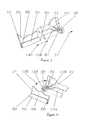
- FIG. 1is a perspective view of a preferred embodiment of the present inventions showing phantom lines for various glass door positions.
- FIG. 2is a section view of the preferred embodiment shown in FIG. 1 as indicated in FIG. 8 .
- FIG. 3is a broken out perspective view of the front lower right corner of the preferred embodiment shown in FIG. 1 showing in phantom lines how the glass door is mounted.
- FIG. 4is a broken out perspective view of the front lower left corner of the preferred embodiment shown in FIG. 1 showing in phantom lines how the glass door is mounted.
- FIG. 5is an enlarged section of FIG. 1 showing details of the timer, control switch, heater indication light and the vents in the side wall.
- FIG. 6is a perspective view of the section shown in FIG. 2 .
- FIG. 7is the same perspective view shown in FIG. 6 but with the spit plate removed and an alternative fan activated heat removal and cabinet cooling system installed.
- FIG. 8is a section taken through the alternative fan activated preferred embodiment shown in FIG. 7 as indicated in FIG. 7 .
- FIG. 9is a detailed perspective view of the light used to illuminate the cooking interior of the preferred embodiments shown in FIGS. 1 through 6 with the translucent red lens shown in dotted lines.
- FIG. 10is an enlarged detail of FIG. 1 showing in greater detail the upper left corner of the preferred embodiment shown in FIG. 1 .
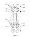
- FIG. 11is a perspective view of a preferred spit assembly including a spit support platform.
- FIG. 12is a sectioned perspective view taken from below of the lid used on the warming/steaming tray unit showing ribbing used to prevent uncontrolled dripping of condensed liquids.
- FIG. 13is a perspective view of the spit assembly shown in FIG. 11 mounting a rotary cooking container.
- FIG. 13Ais a perspective view of an alternative rotary cooking container to the one shown in FIG. 13 but which does not require a separate spit assembly in order to operate.
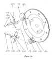
- FIG. 14is a broken perspective section of a kabob rod showing with phantom lines how it mounts into the spit plate.
- FIG. 15is a plan side view of the spit plate and kabob rod shown in FIG. 14 showing how the kabob rod is turned by the drive gear when the spit plate rotates.
- FIG. 16is a perspective view of a food cooking basket showing in phantom lines how the lid for the basket is mounted.
- FIG. 17is a perspective view of the food cooking basket shown in FIG. 16 with food contained within the basket and the basket mounted on the spit assembly.
- FIG. 18is a perspective view of an alternative spit support platform.
- FIG. 19shows the alternative spit support platform shown in FIG. 18 being used to support spit mounted food including use of gloves specifically designed for use in rotisseries.
- FIG. 20illustrates a barbeque grill with a rotisserie spit assembly in accordance with a preferred embodiment of the present invention.
- FIGS. 21 and 22are sectional views of the preferred embodiment of the present invention shown in FIG. 20 .
- An embodiment utilizing the present inventionscomprises a metal enclosure 20 including an essentially horizontal metal floor 22 and metal roof 24 , a generally vertical metal back 26 , and two essentially vertical side walls including a double paneled right side wall 28 and a double paneled left side wall 30 , and an inclined glass front door 32 .
- a curved metal section 34 containing louver vents 238joins the generally vertical metal back 26 to the essentially horizontal metal roof 24 .
- Two horizontal front-to-back running rod-like side rails 38 40one located below the double paneled right side wall 28 and one disposed below the double paneled left side wall 30 , support the metal enclosure 20 and raise it off a countertop 42 or flat surface on which it might rest.
- Four rubber feet 44 , 46 , 48 located on the bottom 52 of the side rails 38 40keep the rails 38 40 from scratching countertops 42 and help prevent the embodiment from skidding.
- the side rails 38 , 40have lifting handles 54 , 56 projecting from their sides, one 54 projecting rightward from the right side rail 38 , and one 56 projecting leftward from the left side rail 40 . These lifting handles 54 , 56 allow the embodiment to be lifted and carried.
- the side rails 38 , 40also incorporate two cord winding projections 58 , 60 extending rearward, one 58 from the back of the right side rail 38 and one 60 from the back of the left side rail 40 .
- These cord winding projections 58 , 60serve to wrap the cord for shortening its length, or for storing the cord while carrying the embodiment or during storage, or for other reasons.
- the cord winding projections 58 , 60also keep the back 26 of the embodiment from directly contacting a vertical back wall.
- the glass front door 32is essentially a single flat panel of glass 64 with a round steel axle rod 66 held along its lower edge 68 by a “U” shaped channel 70 which is silicone glued to both the lower edge 68 of the panel of glass 64 and the axle rod.
- This axle rodextends outward 72 , 74 from both lower corners 76 78 of the panel of glass 64 .
- the rails 38 , 40provide tracks 81 , 83 which engage and support the two ends 80 , 82 of the round steel axle rod 66 which extend horizontally from each lower corner of the lower edge 68 of the glass front door 32 , and this engagement with these tracks 81 83 controls movement of the glass front door 32 to pivot downward 84 from the door's 32 closed position 85 and to slide under 87 the metal enclosure 20 .
- handles 90 , 92In the upper right corner 86 of the panel of glass 64 and the upper left corner 88 , there are two handles 90 , 92 , one for each corner 86 , 88 , which have rod-like grips 94 , 96 which extend horizontally outward 72 , 74 in opposite directions. By making the grips extend horizontally instead of vertically, the overall height of the embodiment is minimized. This may be particularly advantageous in placing the embodiment below over counter cabinets or other overhead objects.
- the handle geometryis such that either handle 90 , 92 or both handles 90 , 92 may be easily used to grip and open or close the glass door 32 , or slide it 32 under 87 the metal enclosure 20 or hold the door for other reasons such as removal.
- the inclined glass door 32may be held closed 85 by gravity alone, requiring no other latching mechanism.
- this preferred embodiment door constructiongenerally: reduces required assembly parts, simplifies manufacturing, makes manufacturing tolerances wider, and makes user operation easier and more reliable.
- the inclined glass door 32When compared to a vertical glass door, the inclined glass door 32 also typically permits more ambient light to enter the cooking cavity and allows viewing of food being cooked from a broader range of vertical angles, thus making viewing of the food being cooked easier and more convenient. This in turn makes it easier to determine cooking progress and turns cooking of rotisserie food into an entertaining and taste tantalizing show.
- a light 98 mounted between the panels 99 101 of the double paneled right side wall 28introduces additional light into the cooking cavity 104 and further adds to the food viewing advantages just stated.
- This light 98has a frosted translucent glass cover 100 which is in a contiguous plane with the interior wall 101 of the double paneled right side wall 28 .
- This cover 100separates the light bulb 98 from the cooking cavity 104 .
- the light bulb 98has a shiny metal reflector 106 behind it which backs onto the outside wall 99 of the double paneled right side wall 28 .
- the light 98is wired to come on any time the embodiment's heat coil 110 is on.
- a translucent red colored lens 112penetrates the reflector 106 located behind the light bulb 98 and penetrates the outside panel 99 of the double paneled right side wall 28 . Light shines through this red colored lens from the light 98 whenever the light bulb 98 and thus the heat coil 110 is on.
- This red colored lens 112is visible on the outside of the right side wall 99 and gives a clear visible indication of when the heat coil 110 is operating.
- Using a single light 98 to both illuminate the interior of the cooking cavity 104 , as well as give indication on the outside of the embodiment of when the heat coil 110 is operatingcuts down on required parts, simplifies embodiment construction, and increases embodiment reliability.
- Such a operation warning lightmay also meet the requirements for an “on” indicator as set by safety regulatory bodies such as Underwriters Laboratories.
- the lens colormay also be changed, as an example to green, to match foreign safety standards such as those established by TUV in Germany.
- the glass door 32is silk printed 114 , 118 with trademark, decoration and safety markings.
- markings 114may be printed in translucent inks which may be back lit by illumination from the light 98 mounted into the double paneled right side wall 28 .
- Such glowing back lit markings 114may be thus made to be much more visible and dramatic, especially in dark rooms, than similar common unlit markings.
- Markings 114 on the panel of glass 64may by placed to block glare from light 98 mounted into the double paneled right side wall 28 from shining into viewer's eyes thus making the embodiment more pleasant to look at due to less emitted light glare.
- Markings 118 on the door 32may match the color of the enclosure door 32 frame 116 which backs portions of the glass door 32 when the door 32 is closed 85 . Such markings 118 when viewed against the background of the like colored enclosure frame 116 when the door 32 is closed 85 , may be virtually invisible. When the glass door 32 is lowered 84 , however, the markings 118 may become very visible. Thus a warning marking such as “Caution-Hot Surface” 118 may be printed to appear mirror imaged and upside down over when it is virtually invisible while the door 32 is closed 85 and the marking 118 is displayed against the like colored frame 116 background. When the door 32 is lowered 84 and opened 134 , 87 , however, the marking 118 may become clearly visible and appear in proper orientation, that is right side up and not mirror imaged, reading correctly “Caution-Hot Surface”.
- any inclination past verticalmay be used for the glass front door 32 , but an angle between five and twenty-five degrees has been found to be most advantageous for producing satisfactory door latching and food viewing, as well as for conserving valuable countertop-space. Too flat a glass angle stretches out the bottom of the enclosure and consumes an unacceptable amount of countertop space. Too steep a glass angle won't allow proper door latching and provides a poor view of foods being cooked. Inclining the front of the enclosure increases the enclosure's footprint on a countertop and thus increases its stability and decreases any tendency to tip over or be accidentally moved.
- This embodimentmay be constructed at any scale. However, two sizes have been found to be particularly advantageous. For large families, or for parties and entertaining, an enclosure with cooking cavity 104 interior dimensions between eleven and thirteen inches wide side to side, ten to twelve inches from the cooking cavity ceiling 142 to the top of the drip pan 120 , as explained later herein, and ten to twelve inches deep from the inside of the glass door 32 to the front of the heating rods 110 , as explained later, as measured horizontally midway between the ceiling 142 and the top of the drip pan 120 . When constructed at this scale, the embodiment can cook a fifteen pound turkey, or two six pound chickens. Fifteen pound turkeys are considered among the largest turkeys commonly sold around Thanksgiving and Christmas. And six pound chickens are among the largest commonly sold popular chickens sold in U.S. supermarkets. Thus such a size meets the needs of most large families or people who entertain.
- a second advantageous sizemeets the needs of smaller families, people who live alone, or people with very small kitchens.
- a cooking cavity 104with interior dimensions between nine and eleven inches wide, seven to nine inches from the cooking cavity ceiling to the top of the drip pan, and seven to nine inches deep from the inside of the glass door 32 to the front of the heating rods is particularly advantageous.
- the embodimentcan cook a six pound chicken, or two three pound chickens. Three pound chickens are among the smallest commonly sold chickens. This size thus meets the needs of most smaller families or people who live alone.
- the inclined glass front door 32may rotate downward 84 and following such rotation to an essentially horizontal position 85 , slide under 87 the metal enclosure 20 with glass front door's 32 axles 80 82 engaging into the tracks 81 , 83 in the two front-to-back side rails 38 , 40 .
- the top 126 of the glass door 32is held off the countertop 42 by flat horizontal ribs 91 , 93 in the side rails 38 , 40 .
- the glass door 32is out of the way of foods being loaded into or removed from the cooking cavity 104 . This is particularly advantageous when the door 32 is hot and user contact with it might cause burns.
- the enclosure 20may be placed on the edge 30 of a countertop 42 and the glass door 32 may be rotated below the countertop 42 level 132 where it will also be out of the way of food loading and unloading.
- the glass door 32may be opened 134 onto a countertop by being rotated down 84 from its closed position 85 to the countertop.
- the glass front door 32is also removable for cleaning, food loading, or other purposes.
- this removalis accomplished by moving the door's 32 left axle 82 out of engagement with the track 83 in the left side rail 40 by sliding the axle 82 through a slot 138 located in the front of the left side rail 40 .
- the right axle 80is pulled out of engagement with the track 81 in the right side rail 38 by moving the glass door 32 and the attached right axle 80 to the left 140 , away from the right rail 38 .
- Reinstalling the glass door 32is done by reversing the above procedure.
- the door 32may be washed in a dishwasher, or sink, or immersed in liquid.
- constructionwhen compared to doors which have framed glass, construction is generally: simpler, has fewer parts, is less expensive, and is lighter in weight for comparable transparent viewing area. Appearance is also typically cleaner. And the viewing area is unsurpassed compared to most other constructions.
- a warming/steaming tray unit 144comprising a lower heating pan 146 , an intermediate steaming tray 148 with holes 149 in its floor which rests down into the lower heating pan 146 , and a warming tray lid 150 which caps and encloses both the lower heating pan 146 and the intermediate steaming tray 148 .
- This unitis supported by four frustum conical feet 152 projecting from near each of the four corners of the bottom of the lower heating pan 146 , each of the feet 152 which rests into its own two level inverted wedding cake shaped support indention 154 located near each of the corners of the roof 24 of the metal enclosure 20 .
- Each foot 152may rest in the lower most level of each such indention 154 allowing direct contact between the roof 24 of the metal enclosure 20 and the floor 156 of the lower heating pan 146 ; or each foot 152 may rest at the next level up of each indention 154 providing an air space 158 between the roof 24 of the metal enclosure 20 and the floor of the lower heating pan 146 , thus lowering the temperature of the floor 156 of the lower heating pan 146 and the temperature inside the warming/steaming tray unit 144 .
- Such temperature controlmay be used in warming, cooking or steaming foods or in any combination of these functions or other functions—i.e. steaming vegetables and then keeping them warm.
- the warming/steaming tray unit 144may be used to warm, cook or steam foods, either simultaneous with rotisserie cooking or independent of it. And it may perform these functions either with or without the intermediate steaming tray 148 in place, and either with or without the warming tray lid 150 in place.
- Handles 160 on either side of the heating pan 146make it easy to lift the entire warming/steaming tray unit 144 , with or without the intermediate streaming tray 148 , and with or without the warming tray lid 150 in place.
- the placement of the warming/steaming tray feet 152is symmetrical both front to back and side to side thus allowing the user to place it 144 on top of the metal enclosure 20 with a given heating pan handle 160 on the right side or on the left side of the metal enclosure 20 .
- Watermay be placed in the lower heating pan 146 and the intermediate steaming tray 148 put in place to facilitate the steaming of vegetables or other foods.
- droplets of waterWhen foods are being steamed or when moist foods are being heated in the warming/steaming tray unit 144 , droplets of water generally condense on the warming tray lid 150 . These droplets may present a safety hazard when the user lifts off the lid because the droplets may be hot and tend to run to the side of the lid 150 and drop onto the user when the lid is lifted and tilted. As shown in FIG. 12, to help prevent this from happening, the lid 150 has several concentric “V” shaped ribs 151 on the underside of its top surface. When the lid 150 is lifted and tilted, water droplets on this surface begin to run to the side of the lid 150 .
- the warming tray lid 150may be constructed of any of many suitable materials. It would be advantageous for it 150 to be translucent or transparent so cooking or steaming progress as well as the food being cooked could be observed without removing the lid 150 . Glass or plastics such as polypropylene, polycarbonate, or UltemTM from GE Plastics might be suitable for use in constructing the lid 150 as examples.
- the warming tray lid 150has a handle 153 in the center of its outside top surface to help in its use. This handle 153 is textured to help prevent slippage.
- a drip pan 120which mounts inside it, and is covered by, a grate cover 162 .
- the drip pan 120collects grease, oil, and liquid which come from the food being rotisserie cooked.
- the grate cover 162is a metal cover perforated with slots 163 which reduces splashing, and smoke, and flares from liquids from the rotisserie cooked foods splashing and hitting heat coils 110 and other hot surfaces, and diminishes the risk fire from hot grease and oil inside which has dripped from rotisserie cooking food into the drip pan 120 becoming overheated and igniting.
- the drip pan 120 and capping grate cover 162may be pulled out 164 to facilitate their own cleaning, or the embodiment's interior cleaning, or for other purposes.
- the grate cover 162 and underlying drip pan 120both tend to get dirty during rotisserie cooking.
- bothare covered on their upper sides with a nonstick coating similar to that used in nonstick fry pans.
- Such coatinggreatly reduces cleanup, particularly on the grate cover 162 which may get grease, oil and residue dripped on it while simultaneously being exposed to high heat from the heat coil 110 which bakes the drippings on.
- the drip pan 120may be pulled out part way 166 to prevent grease and oil from dripping onto counter tops or the glass front door 32 when food is being prepared for cooking in the spit track rest position 168 , as explained later, or when food is being removed from the metal enclosure 20 after cooking.
- the grate cover 162 and drip pan 120are each square, thus allowing the user to place the grate cover 162 in the drip pan 120 with any given corner of the grate cover 162 resting in any corner of the drip pan 120 , and allowing the drip pan 120 to be placed in the metal enclosure 20 with any of its four corners resting in any corner of the metal enclosure 20 .
- the embodiment's spit assembly 170comprises a first metal spit plate 172 and a second metal spit plate 174 .
- the first metal spit plate 172has two sharpened cylindrical spit rods 176 , 178 attached at right angles to it.
- This first metal spit plate 172is circular in outline with gear teeth 180 on its periphery and eight evenly spaced essentially round kabob holes 182 penetrating it just inside of and adjacent to the gear teeth 180 .
- These kabob holes 182are for supporting kabob rods 184 as explained later.
- the center of the first metal plate 172is frustum conically indented away from the projecting attached spit rods with a stub axle 186 projecting from the back bottom center of the plate's 172 frustum conical indent.
- the stub axle 186has circular grooves 188 cut into its cylindrical periphery. These grooves 188 help to prevent squeaking from the stub axles rubbing against their support tracks 198 , 200 , described later, when the spit assembly 170 is rotating.
- the second metal spit plate 174is the mirror image of the first metal spit plate 172 except in place of the two attached spit rods 176 , 178 it has two short spit rod support tubes 192 attached. These tubes 192 receive, and hold by an overlapping friction fit, the sharpened ends of the two spit rods 176 , 178 .
- Foodsare secured to the spit simply by running one or both of the two sharpened spit rods 176 , 178 through the food and then capping the rods by pushing the tubes 192 in the second spit plate 174 over the sharpened ends of the spit rods 176 , 178 projecting from the first spit plate 172 .
- the foodis then easily inserted into the embodiment as explained later.
- the spit assembly 170 of this embodimenthas several advantages over other available spit assemblies. It's compact and efficient in the use of space both inside and outside the cooking cavity 104 . Because the spit assembly 170 is placed straight into the cooking cavity without angling or sliding into a drive socket, and because no drive forks or other space robbing mechanisms are required to hold even large and heavy pieces of food, almost the entire length of the spit rods 176 , 178 , which run almost the full width of the cooking cavity 104 from the interior left oven wall 103 to the interior right oven wall 101 , may be used to cook food. Other available spit rods, because they must be angled into place and slid into a drive socket are far less efficient in cooking space utilization.
- spit rods 176 , 178on the preferred embodiment there is no loss of space outside the cooking cavity 104 while foods are being loaded into or are being cooked in the cooking cavity 104 .
- Other available spit rodshave handles which project beyond their cooking enclosure and waste valuable counter space.
- the spit assembly 170 on this embodimentholds foods more firmly than other single spit rod designs. This advantage means that even heavy and large foods rotate solidly with the spit assembly 170 and don't become loose and flop or fall off the rods 176 , 178 . On other spit rod designs, foods tend to shift while rotating and become loose and fall off the spit rods when this looseness bores a hole through the food being cooked.
- the spit assembly 170 on the preferred embodimentalso integrates the mounting of self-rotating kabob rods into its design. Many other spit rod designs don't even plan for the mounting of non-rotating kabob rods.
- spit assembly 170 on the preferred embodimentalso allows for the easy and solid mounting of other cooking accessories such as cooking baskets 270 .
- Other spit rods designsmay make no such provisions.
- the spit assembly 170 on the preferred embodimentmakes food mounting easy.
- the foodis simply pushed onto the two relatively skinny and sharp spit rods 176 , 178 , the second spit plate 174 slid into place, and the assembly, food and all, is placed directly into the cooking cavity 104 .
- Other designshave thicker spit rods which are more difficult to shove through foods, and these designs may require hard to use accessories, such as mounting forks, to secure the foods from rotating independently of the spit while cooking, and placing foods into their cooking enclosures is more difficult, as explained in the next paragraph.
- the spit assembly 170 on the preferred embodimentis easy and intuitive to load into the cooking cavity 104 .
- the assembly 170is simply shoved directly into the cooking cavity without angling or having to align its end with and slide it into a drive socket.
- Other designs with drive sockets or other complicated drive meansare far more difficult to use.
- the assembly 170is simply slide straight out of the cooking cavity 104 , the second spit plate 174 easily removed, and the foods slid off the two rods 176 , 178 .
- Other spit rodsare difficult to remove from their cooking enclosures, some requiring the attachment of handles or lifting devices, and/or angling to uncouple drive mechanisms, and may require the additional steps of removal of accessories, such as food mounting forks.
- the spit assembly 170 on the preferred embodimentmay be mounted closer to the cooking heat source 110 to speed cooking of smaller foods.
- Other spit rod designsdon't offer this feature.
- spit rods 176 , 178are cleaned by nonstick coating, similar to that used in nonstick fry pans, covering their surfaces which contact food during cooking.
- the ends of the spit rodsmay be left uncoated to facilitate the easy insertion of the rods 176 , 178 into the spit rod support tubes 192 .
- a spit support base 194is supplied with the preferred embodiment.
- This spit support base 194can hold the first spit plate 172 with its spit rods 176 , 178 projecting directly upward. In this position, foods can be easily loaded onto the spit rods 176 , 178 by lowering the foods onto the pointed ends of the rods 176 178 .
- the spit support base 194can be used to help in serving.
- the support base 194possibly after being placed on top of a plate, can hold foods skewered on the vertically disposed spit rods 176 , 178 while the food is being removed from the spit rods 176 , 178 or while the food is being carved.
- a variant 196 of the spit support base 194 shown in FIGS. 18 and 19expands the diameter of the support base 194 and allows the expanded diameter support base 196 to be used for all of the original 194 support base's functions plus it may be used as a serving plate for foods either not skewered or positioned on vertically supported spit rods 176 , 178 .
- this larger variant 196may eliminate any need for a plate when the support base is used as a serving platform holding the spit assembly 170 with its rods 176 , 178 disposed vertically.
- this spit support base variant 196may also be used to help load and unload foods into and from the embodiment.
- the support base 196is placed under the food, and the support base 196 along with the food which it supports is lifted and moved to load the food into, or remove the food from, the enclosure 20 .
- any dish shaped devicemight be used to help load and unload food to and from the enclosure 20 .
- Such a shapeis enhanced for this use if its perimeter is raised in a manner similar to that found on a soup bowl. Such a raised perimeter helps better support the foods being inserted into or removed from the enclosure 20 and more reliably holds liquids which may drip form such foods.
- Either the original 194 or the variant 196 spit support basemay be used to keep the spit assembly 170 from rolling on a countertop.
- one of the spit plates 172 , 174is placed into either an upright or inverted spit support base 194 , 196 resting on the countertop which thus prevents the spit assembly 170 from rolling by providing a stable indention, i.e. either the top face or bottom face of the support base 194 , 196 resting flat on the counter, in which one of the round spit plates 172 , 174 may rest.
- the spit assembly 170is ready to be loaded into the embodiment enclosure 20 .
- the double paneled right side wall 28 and the double paneled left side wall 30each contain an indented spit support track 198 200 on their interior panels 101 , 103 .
- the spit support track 200 on the interior panel 103 of the left double paneled side wall 30is a mirror image of the spit support track 198 on the interior panel 101 of the right double paneled side wall 28 .
- each track 198 , 200engages the stub axles 186 on the spit plates 172 , 174 when the spit assembly 170 is slid into the enclosure 20 .
- the tracks 198 , 200allow the spit assembly 170 , including any spit accessories or any food thereon, to slide in and out of the enclosure 20 .
- each track 198 200has three axle positioning indents 168 , 122 , 202 which can support and hold the stub axles 186 , and thus the spit assembly 170 . in specific track 198 , 200 locations.
- the first 168 of these axle positioning indents 168 , 122 , 202is located on each track 198 200 adjacent to the door 32 opening.
- This indent 168is referred to as the rest position and has several functions. First, when loading or unloading food from the embodiment, it may be first rested in this position 168 where a better grip may be obtained on the food or where it simply may be rested. It also serves as the first location to catch the spit assembly 170 as it's being loaded into the embodiment, and the last location to catch the spit assembly 170 before it leaves.
- foodscan be centered on the spit rod, or ties to secure the wings and legs on a chicken might be readjusted, or barbeque sauce can be brushed on a chicken or baby back ribs, or seasonings applied to other foods.
- the rest position 168When the rest position 168 is being used for food preparation, it may be advantageous to pull the drip pan 120 and attached grate cover 162 to their part way out position 166 , as explained earlier, to keep foods and preparations from dripping or dropping onto the countertop or glass door.
- each spit support track 198 , 200is backed by an upwardly inclined track portion 204 .
- This inclined track 204combined with the large open front throat of the track and rest position 168 , makes it easy to catch the spit assembly 170 and hold it in the rest position 168 when it's inserted into the enclosure 20 , and it makes it obvious that the spit assembly 170 has been caught in the rest position 168 when it is being removed from the enclosure 20 .
- the tracks' 198 , 200 lowered front portionsallows foods to duck under the enclosure's roof 24 front overhang 206 , thus allowing larger foods to be loaded into the enclosure 20 .
- the roof 24 front overhang 206is necessary to give strength to the front of the roof 24 , and without lowering the front of the track, the size of the foods which might be loaded into the enclosure 20 could be reduced and be smaller than the capacity of the enclosure 20 itself.
- the assembly 170When the spit assembly 170 is being loaded into the enclosure 20 , the assembly 170 first passes the rest position 168 , then the inclined track portion 204 , and next it comes to the low heat position 122 where its stub axles 186 can be engaged by gravity into a detent 168 , 122 , 202 and rotate. In the low heat position 122 the gear teeth 180 on the perimeter of the spit plate closest to the right side inner side wall 101 engage a motor driven drive gear 208 which penetrates into the enclosure through the right side inner side wall 101 . The spit assembly 170 and any spit accessories or food thereon, may be rotated by this motor driven drive gear 208 in front of the embodiment's rear heating element 110 , which is described later herein.
- a quick and easy method of tying up loose parts of foods to be rotisserie cookedhas been found using the spit support track 200 , timer 222 and control switch 224 .
- wings and legs on chickens, ducks and turkeyscan be easily secured using this method.
- the end of a length of stringis secured to a wing, leg or other part of the fowl using a simple wrap or a slip knot as examples.
- the end of the stringmight be indirectly secured to the fowl by securing the string to the spit assembly 170 . This might be done while the fowl is supported on the spit assembly 170 in the spit support track 200 rest position 168 or while the fowl is outside the embodiment.
- the spit assembleis moved back to either the low heat 122 or high heat 202 spit support track 200 position.
- the control switch 224is then turned to the “no heat rotation” 252 position and the timer turned on.
- the stringautomatically wraps around the fowl's loose parts thus securing them.
- the timeris turned off, the string is cut, and its end tied or wrapped or otherwise secured to the fowl on a wing, leg or other part.
- the cut end of the stringmight be indirectly secured to the fowl by securing the end to the spit assembly 170 .
- the direction of spit assembly 170 rotationis important in producing satisfactory cooking results.
- the embodiment's heating element 110is located half way up, and directly adjacent to, the back 26 wall of the enclosure 20 .
- the drive gear 208rotates the spit assembly 170 so food rotate 175 from the top of the enclosure 20 down to directly in front of the heating element 110 and then down to the bottom of the enclosure where the food rotates 175 back to the top of the enclosure 20 while the food faces away from the heating element 110 . Reversing this rotation 175 has been found to result in smoke, small flare-ups and less tasty food.
- the speed of spit assembly rotationhas also been found to be important in producing rotisserie cooked foods with generally superior taste and texture.
- the preferred embodimenthas a spit assembly 170 rotation speed of between 3.5 and 5 rpm. This is typically faster than most home rotisseries operate
- the low heat position 122may support large foods up to the capacity of the enclosure 20 . However, it may also support foods of any size including smaller sized foods. In some cases the low heat position 122 may be desirable to cook smaller foods slower as an example.
- Rotisserie cooking in the preferred embodimentdiffers in several ways from conventional oven cooking.
- conventional oven cookingthe food remains stationary and is cooked by hot air.
- foodis rotated about a horizontal axis and is cooked by a combination of both radiant energy coming directly from the heat coil 110 and air heated by the heat coil 110 .
- Radiant energyis generally more efficient than hot air in conveying cooking energy to food and thus typically gets foods hotter quicker.
- radiant energytends to dry out and burn foods as is the case in most conventional oven broilers. Also, without food rotation, radiant energy tends to cook grease and oil into foods, and particularly into meats.
- Rotisserie cooking in the preferred embodimentis generally quicker than conventional oven cooking. This is partly due to the efficiency of radiant energy heating and also due to food movement which helps break the air boundary layer around foods being cooked and thus speeds hot air heat transfer to foods in a similar manner to fan driven home convection bake ovens.
- Cooking speedis also increased because foods are alternately super heated on their surfaces as they pass directly in front of the heating coil and then the heat is allowed to soak into the foods as they rotate away from the heating coil.
- the high heat track position 202Directly behind and above the low heat track position 122 , is the high heat track position 202 .
- the stub axles 186 of the spit assembly 170may be pushed back, raised and rested into this position.
- the gear teeth 180 in the perimeter of the spit plate closest to the right side inner side wall 101may engage the drive gear 208 and the spit assembly 170 may be thus power rotated.
- Smaller foodsmay be rotated closer to the heating element 110 in the high heat track position 202 which may greatly reduce such smaller foods' cooking times.
- Inserting the spit assembly 170 into the preferred embodimentrequires only resting it on the left and right spit support tracks 200 198 and lifting and pushing it back into the enclosure 20 to the desired use position 168 , 122 , 202 , be it the rest position 168 , the low heat position 122 or the high heat position 202 .
- Removing the spit assembly 170 from the high heat track position 202 , the low heat track position 122 , or from the rest track position 168 ,requires only lifting and pulling the spit assembly 170 toward the front of the enclosure 20 .
- the spit plate's 172 , 174 large outer diameter gear 180greatly reduces the play and backlash in the motor speed reduction gear drive train caused when off-center weighted foods are rotated.
- the motorpushes off-center foods uphill until the off-center weight swings over the top of center and then moves downhill constrained by the drag of the motor.
- the shift from the motor pulling the food uphill to the motor constraining the food's movement downhillcauses a shock load on all the gears in the gear reduction train, and particularly on the final drive gears, as any free movement, or play, between the gears in the gear train shifts with the full power of the off-center weighted foods behind it.
- Typical final drive gears found in rotisserie drive trainsare one-tenth or less of the diameter of the spit plate's outer gear teeth 180 and thus generally are far less durable, have far more play, and put far more load on both the spit and attached food, and on the rest of the reduction drive gear train itself. This in turn may result in shorter motor and gear life, food disengaging from and falling off of the spit rod, and unacceptable levels of noise and vibration.
- the speed reduction between the drive gear 208 and the gear teeth 180 on the spit plate 172 , 174is ten-to-one in the preferred embodiment but may be greater or less depending on the desired diameter of the spit plate and the coarseness needed in the gear teeth.
- such a high gear reduction outside of the gear transmission 210 attached to the gear reduced motor 212means that fewer and less durable, which may translate to less expensive, gears may be used inside the gear transmission 210 attached to the gear reduced motor 212 .
- Both the first 172 and the second spit plates 174each have eight evenly spaced kabob holes 182 penetrating their structure just inside their perimeter gear teeth 180 . These holes 182 are designed to hold the ends of self rotating kabob rods 184 . Each kabob hole 182 is essentially circular hole passing through the spit plate 172 , 174 with four evenly spaced semicircular lobes 214 carved into its perimeter.
- Each kabob rod 184has a pointed end 216 , and an end with a drive cam 218 and retaining spring 220 .
- the kabob rods 184work by the spit assembly 170 first being put together with the spit rod holding tubes 192 on the second spit plate 174 being pushed over the pointed ends of the two spit rods 176 178 projecting from the first spit plate 172 .
- Each kabob rod 184 to be usedis then loaded with food by skewering the food onto the kabob rod 184 using its pointed end 216 .
- Any number of kabob rods 184may be used at any one time, from one up to the spit assembly's 170 capacity of eight.
- the pointed end 216 of the kabob rod 184is inserted through a kabob hole 182 in the spit plate 172 , 174 which will be closest to the inner panel 103 of double paneled left wall 30 . Then the rod 184 is backed into an opposing hole 182 in the other spit plate 172 174 where the retaining spring 220 , as its widest 183 part passes through the kabob hole, snaps and retains the kabob rod 184 from side to side movement away from or toward either spit plate 172 , 174 similar to the way a clothing snap works. This insertion process is easy and intuitive and is repeated for each kabob rod 184 to be used.
- Insertion of the kabob rods 184 onto the spit assembly 170may be done while the spit assembly 170 is outside of the enclosure 20 or while it is placed in a track position inside the enclosure 20 , such, as an example, as being placed in the rest position 168 .
- the spit assembly 170 with attached kabob rods 184is then inserted into the low heat track position 122 , and the embodiment turned on by setting the cooking time on the timer 222 and turning the control switch 224 to the “Normal Heat Rotation” position.
- each 350 degree rotation 175 of the spit assembly 170causes each kabob rod 184 to be rotated 177 one-quarter turn by the kabob rod's 184 drive cam 218 being rotated by the spit plate 172 , 174 into the drive gear 208 which forces one of the kabob rod's cam 218 arms striking the drive gear 208 to move and consequently causes the one-quarter turn rotation of the kabob rod 184 .
- the four lobes 214 in each of the spit plate 172 , 174 kabob holes 182help stop each kabob rod 184 at even one-quarter turn intervals, and also help prevent a kabob rod 184 from rotating in its kabob hole 182 when it is not being driven by the drive gear 208 pushing on the kabob rod cam 218 .
- This kabob rod 184 automatic rotationresults in all sides of the kabob rod cooked food being cooked evenly, unlike in most rotisserie kabob cooking where one side of the kabob food gets cooked more than the opposite side.
- the kabob rods 184 on the preferred embodimentare better than others commonly available for several reasons. First, they 184 may automatically rotate, as explained above, which cooks kabob foods more evenly on all sides than non-rotating rods.
- one, or up to the spit wheel's capacity of eight kabob rodscan be in use at any time.
- Some kabob rodsrequire the entire transport wheel to be loaded with kabob rods in order to operate.
- the rods 184can be inserted or removed while the rods 184 are inside the cooking cavity 104 .
- Many kabob rodsrequire a lot of space to be inserted or removed from their transport wheel, and thus they could not be inserted and removed from inside a confined cooking space.
- the rods 184are very efficient in space utilization and allow foods to be placed along most of the rod's 184 entire length.
- the rod's 184 means of attaching to their transport wheels 172 , 174is compact and therefor allows more room for cooking foods with less wasted space for attachment to the transport wheels 172 , 174 .
- Many kabob rodsuse a substantial portion of their length for coupling which limits their cooking space.
- kabob rods 184intuitively snap into place which makes them easy to use. This also generally removes the need for user instructions. Many kabob rods have complicated coupling mechanisms which are both difficult to use and require detailed user instructions.
- the rods 184offer the ability for each rod 184 to automatically rotate or remain stationary at the user's discretion and in any combination (i.e. 3 rotating and 2 remaining stationary all simultaneously) simply by the user facing the rod's cam 218 toward or away from the drive gear 208 side of the cooking cavity 104 . This feature is not found on other kabob rod designs.
- a serpentine shaped electric heat coil 110directly adjacent to, and approximately half way up the back 26 of the enclosure 20 of the preferred embodiment, is a serpentine shaped electric heat coil 110 .
- This coil 110winds back and forth across the back 26 of the enclosure 20 creating four straight heat rods 226 terminated by three “U” turns 228 and two rods passing through the enclosure's right side interior wall.
- the coilis supported on its right and left ends by support brackets 230 , 232 which slide over the “U” turns 228 in the coil and position it to allow for expansion and contraction as the coil heats and cools, while maintaining the coil's correct position.
- This heat coil 110unlike heating elements in conventional ovens which turn on and off under thermostatic control, may remain constantly on during cooking. This minimizes cooking times and simplifies embodiment construction when compared to rotisseries which cycle on and off while cooking. Alternatively the heat coil 110 may be thermostatically controlled and forgo these advantages.
- the embodimentis continuously heating air inside the enclosure 20 , and is constantly radiating cooking energy.
- the preferred embodimentobviates the need for safety devices such as safety thermostats and thermal fuses designed to protect the device if a user set thermostat should fail. This further simplifies construction of the embodiment when compared to most conventional oven constructions.
- Some rotisseriesplace their heating elements or sources of heat below the spit. This may create safety problems from grease fires and flare ups. When grease, oil and residue collected in drip receptacles below the spit become overheated from a heating source located below the spit, smoke and fires can result. When grease, oil or other residue drip or splash onto heating elements, other heat sources, or other hot surfaces, fire and smoke can also result. Heat sources located below the spit also tend to raise the overall height of the rotisserie which may be a problem when it is used in kitchens with cabinets located over their countertops.
- Some enclosed rotisseriesplace their heating source above the spit assembly. These elements, due to their locations, and because both radiant and convection heat given off by the elements tends to rise, are generally less efficient than heat sources placed lower in the cooking enclosure 20 . This high position also tends to raise the overall height of the rotisserie which may be a problem when they are used in kitchens with cabinets located over their countertops. This problem is compounded by top mounted heating sources superheating the top of the cooking enclosure 20 which in turn may cause heat damage to over-counter cabinets. Such superheating may also create heat and fire safety hazards.
- Both low and roof mounted heating elementsbecause they may have their heat sources located near the middle or front of the rotisserie, may create an increased potential for users burning their hands when inserting and removing foods from the rotisserie enclosure when compared to a back mounted heating element.
- this embodimentplacing its heating element mid way between the floor 22 and ceiling 24 of the embodiment enclosure 20 , problems of both low and high mounted heat sources are overcome.
- this mid way heating element 110 locationhelps minimize the overall height of the embodiment, and greatly reduces any chance of smoke and fires from the contents of the drip pan becoming overheated or from grease, oil or other residues splashing onto heat coil 110 or heat coil warmed hot surfaces.
- this mid locationWhen compared to roof mounted heat elements, this mid location also reduces the temperature of the roof 24 of the embodiment, thus reducing the risk of heat damage to over-counter cabinets and the risk of burning users on the roof 24
- This mid location in the preferred embodimentis also generally more efficient in conveying cooking energy than heat coils mounted above the spit assembly 170 .
- This mid locationwhen compared to heat elements located above or below the spit which generally are closer to the front of the enclosure, also tends to reduce the temperature on the outside of the front door 32 , including the front door 32 glass, which in turn reduces the risk a user will burn themselves on these surfaces.
- the mid heat element 110 locationin general, when compared to heat element locations above or below the spit assembly, reduces all temperatures on the forward exterior of the enclosure 20 where users are most likely to come in contact and potentially burn themselves. This in general reduces user safety hazards both directly from burning themselves on the enclosure 20 or from accidents, such as accidentally dropping hot food, after unintentional contact with such hot enclosure 20 surfaces.
- a removable cleaning shield 234Located directly behind the heating element 110 , and held in place by the left 230 and right 232 heater element support brackets, is a removable cleaning shield 234 .
- grease, oil and residuemay be splattered off food as the food becomes heated in front of the heating element 110 .
- the area behind and adjacent to the heating element 110tends to get dirty. Heat from the heating element 110 bakes on the grease, oil and residue and makes cleanup difficult.
- the cleaning shield 234may be coated with a nonstick ceramic coating similar to that used in many of today's nonstick fry pans. This coating is medium gray in color and thus tends not to show when it is dirty.
- the cleaning shield 234is easy to clean simply by gripping the shield 234 by its bent-over top edge 236 and pulling it up and forward 235 and out of the enclosure 20 . Once thus removed, the shield 234 may be washed in a sink or dishwasher. Reinserting the cleaning shield 234 is accomplished by reversing the removal process.
- the cleaning shield 234receives radiant heat from the element 110 .
- the medium gray ceramic coating on the cleaning shield 234has been found to cook foods as fast or even faster than their shiny counterparts.
- the medium gray ceramic nonstick coated cleaning shield 234gets hotter than a similar shiny cleaning shield. This in turn raises the interior air temperature of the enclosure 20 which in turn reduces cooking times.
- radiant energy striking the medium gray ceramic nonstick coated cleaning shieldis reradiated at a lower infrared frequency than radiant energy striking a shiny cleaning shield. This lower frequency tends to absorb quicker and deeper into foods which in turn results in shorter cooking times.
- the nonstick ceramic coating on the cleaning shield 234by not readily showing when it is dirty, reduces the amount of cleaning that the cleaning shield 234 requires. This same coating, when compared to other surfaces, makes cleaning the shield much easier. Cleaning ease is also greatly enhanced by the cleaning shield 234 being easy to remove from and reinsert into the enclosure 20 .
- the heating element 110 in the preferred embodimentremains constantly on during rotisserie cooking which creates hot air which must be safely vented from the enclosure's 20 interior.
- vents 238Directly behind the heat shield 234 , on the curved center wall section 34 connecting the back 26 of the enclosure 20 to the roof 24 of the enclosure 20 , are upward facing vents 238 . These vents 238 allow air heated by the constantly operating heating element to escape the enclosure's 20 interior. These louvered vents 238 are indented inward with their openings at the top of the indent.
- This arrangement of upward facing louvers 238reduces potential heat damage to overhead cabinets when compared to more conventional indented louvers with their openings at the bottom of the indent. This is because hot air must first rise above the louver 238 and then exit by dropping down into the louver 238 opening rather than simply rising directly through the louver opening.
- gaps 240 , 242 , 244 , 246between the glass door 32 and the frame 116 it rests against on all four sides of the door 32 .
- the gaps on the lower side of the glass door 32generally allow cool air to enter the enclosure's 20 interior, and the gaps around the upper section of the glass door 32 generally allow hot air to exit from inside the enclosure 20 . This air movement helps control interior enclosure 20 temperatures which might otherwise rise to unacceptable levels due to the heat element 110 remaining constantly on during rotisserie cooking.
- the gaps 240 , 242 between the door frame 116 and the glass door 32are exceptionally wide on both the left 242 and right 240 sides of the glass door 32 .
- Hot air exiting out these left 242 and right 240 side gapsis dispersed and broken up by these exceptionally wide gaps 240 , 242 being inclined with the glass door 32 which help form the side gaps 240 , 242 .
- Such dispersion and breakup of the hot air rising from the inclined side gaps 240 242helps prevent heat damage to overhead cabinets which the embodiment might be placed under.
- the interior temperature of the enclosure 20is controlled by the venting already described both on the curved wall 34 connecting the back 26 wall of the enclosure 20 with the roof 24 of the enclosure 20 and the venting from the gaps 240 , 242 , 244 246 surrounding the door.
- An equilibriumis reached involving the cooking energy supplied by heating element 110 , a cooling affect from the cooler temperature of the food being cooked, the amount of venting, and the ambient air temperature of the room in which the embodiment is operating.
- the preferred embodimentis engineered to produce an air temperature measured near the center of the enclosure's 20 interior of around 250 to 375 degrees Fahrenheit. Such a temperature, when compared to both warmer and cooler cooking temperatures, has been found to produce exceptionally satisfactory results in rotisserie cooked food taste and texture.
- FIGS. 7 and 8An alternate form of controlling cooking temperatures is shown in FIGS. 7 and 8.
- the shaft of the gear reduced motor 212is extended through the case of the gear transmission 210 and a radial fan 258 is attached to the end of the motor's shaft.
- This fan 258pulls through it both cool air 260 from outside of the enclosure 20 as well as hot air 262 from inside the enclosure 20 .
- the cool air 260 and hot air 262are mixed and the combined warm air move into the space between the interior wall 101 and outside wall 99 of the double paneled right side wall 28 .
- a long scoop shaped vent 264 adjacent to the right side of the glass door 32directs warm air out 266 over the exterior of the glass door when the embodiment is on and cooking with the glass door 32 closed. This directed warm air 266 cools the exterior of the glass door to help lower its temperature and thus the chances of a user getting burned by touching its surface.
- vents 268 at the top of the double paneled right side wall 28direct 280 the warm air moved by the fan 258 out 280 over the metal roof 24 of the enclosure 20 thus cooling the roof 24 and lowering its temperature to reduce the risks of burns from users accidentally touching the roof 24 when it is hot. Air from these vents 268 is blocked when the warming/steaming tray unit 144 is placed on top 24 of the enclosure 20 thus increasing the heat on the metal roof 24 and allowing the warming/steaming tray unit 144 to function in its normal way.
- ventsmay be placed in other locations around the double paneled right side wall 28 , such as example adjacent to the curved metal section 34 or back 26 of the enclosure, to help vent the interior of the enclosure 20 and reduce the chances of accidental burns from a user touching that section 34 , 26 by mistake.
- the enclosure 20is generally symmetrical side to side when viewed from the front. However there a few exceptions to this.
- a control/motor housing 248mounted to the outside panel 99 of the double paneled right side wall 28 .
- the control/motor housing 248has a power cord 250 extending out its back and contains within it: a three hour mechanical timer 222 , a control switch 224 , and a gear reduced 210 motor 212 which powers the drive gear 208 , referred to earlier, projecting through the interior panel 101 of the double paneled right side wall 28 .
- the heat element 110also projects from the interior panel 101 of the double paneled right side wall 28 and is supported by brackets 230 , 232 attached to both the right interior side wall 101 and the left interior side wall 103 .
- a light 98 and light reflector 106mounted between the interior 101 and exterior 99 panels of the double paneled right side wall 28 which lights the interior of the enclosure 20 through a translucent glass cover 100 disposed on the interior wall 101 of the double paneled right side wall 28 .
- This light 98has a red lens 112 which extends from the light 98 through the light reflector 106 and exterior right panel 99 to the outside of the double paneled right side wall 28 .
- the control/motor housing 248is attached to the outer panel 99 of the double paneled right side wall 28 .
- the preferred embodimentmounts its controls 222 , 224 more than one-third the way back on its right side. It also mounts the control/motor housing 248 above the bottom of the embodiment, so that more than one-eighth of the outer panel of the double paneled right side wall 28 is left exposed under the control/motor cover 248 to allow items on the countertop 42 on which the embodiment might rest to move and reside under the control/motor housing 248 .
- the surface on which they are displayedis inclined, and inclined both in plan and side views.
- Such double inclinationby facing the controls 222 224 toward the user whose eyes and hands are generally disposed above and to the right side of the enclosure 20 , helps in both the viewing and the use of the controls 222 , 224 .
- the firstis a mechanical three hour count down timer 222 .
- This windup timer 222allows the embodiment to operate for up to three hours without having to reset the timer 222 .
- An electronic digitalcan be substituted to perform the same function.
- Three hoursis appropriate because a fifteen pound turkey takes about 12 minutes per pound to cook or about three hours in total. Thus three hours may accommodate such a large item without having excess time which might result in timer inaccuracies and loss of safety advantages.
- a four hour mechanical timermight have its time markings closer together on its dial and might have a mechanism which is inherently less accurate than a three hour timer. Both of these conditions would reduce the timing accuracy for the user. And safety might be reduced it the user could leave the embodiment for four, five, or six hours, instead of only three hours maximum.
- the second control deviceis a control switch 224 which regulates the functions of the heat element 110 , the gear reduced motor 212 , and the light 98 .
- the control switch 224is only functional when the timer 222 is set and running with time on it. As shown in FIG. 5, the control switch 224 has three positions 252 , 254 , 256 . Starting from the left, the first position 252 called “No Heat Rotation” turns on the gear reduced motor 212 , causing the spit assembly 170 , if installed, to rotate, and turns off both the light 98 and the heat element 110 .
- the light 98 being off, along with no light shining through the red lens 112indicates to the user that the heating element 110 is off and is not receiving electricity.
- This first switch position 252is generally used after foods have been rotisserie cooked to cool the foods down while continuing the rotational flow of juices in and around the foods. It 252 keeps foods moist while not allowing grease, oil and/or other liquids to settle into the foods. It 252 may be used with the glass door 32 open 132 134 87 or closed 85 depending on whether it's desirable to cool the foods to serving temperature rapidly or slowly. If the first switch position 252 is used with an electronic timer, the heat element 110 might be run at lower wattage or cycled on and off during this cooling down period to keep the foods warm for a prolonged period of time.
- the second control switch position 254titled “Normal Rotation”, is used for rotisserie cooking.
- this control switch position 254the gear reduced motor 212 , the heat element 110 , and the light 98 all remain on.
- the light 98 being on, along with light shining through the red lens 112indicates to the user that the heating element 110 is on and receiving electricity.
- foodsare rotisserie cooked for the amount of time set on the timer 222 .
- the third control switch position 256titled “Pause to Sear”, is used to brown or sear the surfaces of foods.
- this control switch position 256the gear reduced motor 212 is turned off, thus stopping the spit assembly 170 from rotating, but the heat element 110 , and the light 98 remain on.
- Using this switch position 256involves rotating the food using either of the other two control switch positions 252 , 254 until the side of the food to be browned or seared faces the heating element 110 , and then turning the control switch 224 to the “Pause to Sear” position 256 .
- the foodwill brown or sear in this position 256 until the time set on the timer 222 expires.
- the gear reduced motoris enclosed in the control/motor housing.
- many types of motors and gear transmissionsmight be suitable, a half inch stack shaded pole motor with spur and helical reduction has been found to produce particularly satisfactory results in the larger size embodiment whose dimensions have been described earlier
- Synchronous motorshave an advantage in generally producing less noise than generally larger shaded pole motors and other motors commonly used in rotisseries.
- Use of the spit plate as an extra large and durable final drive gearallows use of synchronous motors which usually have less durable transmissions than those used on the more expensive shaded pole motors.
- a metal wire basket 270might be fitted.
- This wire basket 270might have a metal wire framework covered with a nonstick coating to prevent foods from sticking to the basket.
- the lid 272 of the basket 270is fitted with a fixed wire tab 274 on one side and a finger retractable wire tab 276 on the opposite side. Each tab fits into one of several slots 278 280 defined by wires on each side of the dished out lower part 282 of the basket 270 .
- the lid 272may be adjusted to clamp onto and hold during rotisserie cooking several different thicknesses of foods.
- the lid 272 and the lower part 282 of the basket 270There is a certain degree of springiness in the lid 272 and the lower part 282 of the basket 270 , and this springiness allows the food 284 being held in the basket 270 to be clamped under pressure between the lid 272 and the lower part 282 of the basket 270 so that the food 284 is prevented from shifting while cooking.
- the same springinessallows different thicknesses of food to be held securely at the same time. Helping this ability to accommodate different thickness food simultaneously, the fixed tab 274 and the finger retractable tab 276 may each be inserted at different heights above the floor 286 of the dished out lower part 282 of the basket 270 .
- Securing food in the basket 270is a simple process.
- the food 284is first placed on the floor 286 of the dished out lower part 282 of the basket 270 .
- the fixed wire tab 274 on the lid 272is slid into 283 one of the slots 278 on the side of the dished out lower part 282 of the basket 270 .
- the slot 278 chosen, and hence the height of the lid 272 above the floor 286 adjacent to the fixed wire tab 274should be slightly lower than the height of the food 284 directly adjacent to the slot 278 .
- the finger retractable wire tab 276is then retracted 288 by squeezing on the movable 290 and fixed 292 handles of the finger retractable wire tab 276 .
- the finger retractable wire tab 276 side of the lid 272is then lowered 294 to clamp the food and the retractable wire tab 288 inserted into one of the slots 280 on the side of the dished out lower part 282 of the basket 270 by releasing finger pressure on the movable 290 and fixed 292 handles of the finger retractable wire tab 276 .
- Attaching the basket to the spit assembly 170is done by simply inserting the two spit rods 176 , 178 through four integral semicircular loops 296 which are part of the dished out lower part 282 of the basket 270 , and then placing the second spit plate 174 over the ends of the spit rods 176 , 178 and inserting the spit assembly 170 with the basket 270 in the normal manner into the cooking cavity 104 .
- the basket 270is centered on the spit assembly 170 and fits between the two spit rods 176 , 178 . This is different than most spit baskets which either have a spit rod running through their center or are placed off center to the spit assembly rotation axis. Those baskets with a spit rod through their center limit their capacity to cook large flat foods such a steaks and fish. Those baskets which are placed off center to the spit rotation axis cook one side of the foods they contain more thoroughly than the other. By contrast, compared to these alternative designs, the basket of the preferred embodiment cooks food more evenly on both sides and has the ability to hold foods up to the full size of the basket. In the real world, both of these are major advantages in rotisserie cooking.
- the fixed 274 and finger retractable tab 276 lid 272 attachment design of the preferred embodimentalso has major advantages over other lid latching designs. As an example, many designs adjust to only one thickness of food.
- the preferred embodimentthrough use of two tabs 274 , 276 which fit into separate slots 278 , 280 which individually adjust their heights, not only allows adjustment to different thickness foods, but allows several different thickness foods to be held in the basket 270 simultaneously.
- the preferred embodimentis springy which allows it not only adjust to different thickness foods being simultaneously held, but allows it also to put clamping pressure on the foods, even foods of different thicknesses, being held in the basket so they won't shift during rotisserie cooking. Shifting foods tend to get damaged and to fall out of the basket.
- Rigid basket designsgenerally don't provide this spring loaded clamping pressure.
- the finger latching mechanism used on the preferred embodimentis also superior in simplicity and ease of use compared to other basket designs.
- the basket on the preferred embodimentmay be secured closed with food in it using only one hand. Many other designs require two hands to close and latch.
- FIGS. 16 and 17illustrate a relatively flat basket, perhaps as an example, one to one-and-a-half inches thick, which would be inserted with the spit assembly 170 in the low heat position 122 and hold such foods as steaks, fish and small vegetables.
- This basket's 270 perimeteris determined by the maximum size which will fit between the first 172 and second 174 spit plates and clear: the heat rods 110 , the glass door 32 , the cooking cavity ceiling 142 , and grate cover 162 .
- a thicker basketperhaps twice as thick as the previous basket 270 but otherwise similar in shape and dimensions to the previous basket, might be made to hold lobster tails, potatoes, and other larger vegetables and foods, as well as hold all the kinds of foods the previous basket 270 might hold.
- Such a thick basketmight also be made which would only extend out to the perimeters of the first 172 and second 174 spit plates.
- Such a basketmight be used when it is mounted to the spit assembly 170 and the spit assembly 170 is supported in the high heat position 202 , closer to the heat coil 110 where the reduced size would now allow the basket to clear. It would hold all the same foods the previous two described baskets could, but in smaller amounts. In return for these smaller amounts due to its restricted size, this basket would cook foods faster when it was placed in the high heat position. 202 This basket could also be used in the low heat position 122 if slower cooking speeds were desirable.
- another accessory which might be included with the preferred embodimentis the rotary cooking container 298 which stir fries and rotary cooks foods such as meats, vegetables, popcorn, shrimp, seafood, etc.
- This containercan also be used with or without rotation but without heat inside the embodiment to marinate meats and vegetables by simply putting the meats or vegetables into the container 298 along with a marinade or rub and leaving the timer 222 in the off position or turning on the timer and placing the switch into the “No Heat Rotation” position.
- the rotary movementif used, helps the marinade penetrate all sides of the meats or vegetables or helps the rubs coat all sides of the meats or vegetables with little or no intervention on the part of the user.
- This accessorycomprises a spit assembly 170 mounted cylindrical tubular housing 300 with at least one opening on one end, such opening 302 which may be covered by a lid or door when cooking.
- Several agitation blades 304project from the interior surfaces of the cylindrical housing 300 , and help move and direct food inside the housing 300 while the housing 300 is being rotated.
- the cylindrical housing 300is mounted onto the spit rods 176 , 178 through holes in the housing's ends 306 308 .
- a shape other than cylindricalmay be used for the tubular housing 300 of the rotary cooking container 298 .
- the tubular housingmight be squarcle (cross between a square and a circle like an old television screen), square, pentagonal, hexagonal, irregular, or other shape in cross section.
- the usermounts the tubular housing 300 onto the spit rods 176 , 178 , puts food and possibly cooking oil, spices, etc. inside the housing 300 though the hole 302 or holes 302 in the ends 306 , 308 of the housing 300 , caps the housing 300 if a cap or door is to be used, and places the spit assembly 170 , including the rotary cooking container 298 with its food contents, into the low 122 or high heat 202 spit mounting positions inside the enclosure 20 .
- the cooking process which follows thisis like normal rotisserie cooking, except foods can be tumbled as they cook inside the container, and if cooking oil is present, a form of stir frying may be performed.
- the rotary cooking container 298may be fabricated from stamped, rolled or cast metal, or from glass or from other appropriate materials well known in the art.
- FIG. 13 AAn alternative rotary cooking container 299 is shown in FIG. 13 A.
- This container 299requires no spit assembly 170 to operate, but instead incorporates integral stub axles 301 303 and an attached spit plate 305 with gear teeth 307 to support and rotate the container 299 inside the cooking cavity 104 .
- Agitators 309 inside the container 299help move and tumble the food during cooking, application of rubs, marination.
- a liquid tight door 311covers an opening 313 in the side of the container 299 through which the container 299 may be loaded and unloaded. Steam and expanding and contracting gasses are vented through a small vent hole 315 located adjacent to one of the integral stub axles 303 .
- This alternative rotary container 299has large useable capacity because there are no spit rods running through its center. It also may be very easy to load and unload due to the large opening 313 in its side. It also has the added advantage that no assembly is required, the container is complete and does not require a spit assembly 170 to be placed through its center to operate. And this container 299 may be used for all the same function of the rotary cooking container shown in FIG. 13 .
- Either the rotary cooking container shown in FIG. 13 or the one shown in FIG. 13Aadd a convenient cooking feature of automatically agitating foods without user intervention. When cooking, this means that foods tend not to burn and may be cooked with little or no oil or fats. Either rotary cooking container may be nonstick coated on their interiors to help facilitate not using fats and oils during cooking. Such coatings are well known in the art and thus are not described in detail herein.
- Inserting and removing foods into and from the cooking cavity 104 of the preferred embodimentis typically an easy process.
- the preferred embodimentincludes a pair of gloves 310 shown in FIG. 19 to simplify the process.
- These gloves 310are different than normal kitchen gloves however.
- Their 310 outer surfaces 312are coated with a flexible, water and grease tight material, like plastic or rubber, similar to a set of dishwashing gloves. This water and grease tight material covers an insulating layer of cotton fabric less than ⁇ fraction (1/16) ⁇ of an inch thick which helps prevent hot foods from burning the user.
- the gloves 310extend over the wrists and cover part of the user's lower arm.
- a usermay lift foods, such as chickens, turkeys, steaks, ribs or vegetables, which are either mounted or not mounted on the spit assembly, both into or out of the preferred embodiment's cooking cavity 104 , when the food is either hot or cold, using the gloves 310 .
- foodssuch as chickens, turkeys, steaks, ribs or vegetables, which are either mounted or not mounted on the spit assembly, both into or out of the preferred embodiment's cooking cavity 104 , when the food is either hot or cold, using the gloves 310 .
- the gloves 310prevent the user's hands from getting dirty or greasy and help protect the user from getting burned when handling hot foods.
- the gloves 310also simplify handling cooked and uncooked foods in general, and make easier the mounting and releasing foods to and from the spit assembly by removing concerns the user might have of getting dirty and greasy, and getting burned when directly using his or her hands to help perform these tasks.
- the gloves 310can also help protect the user from cuts which he might get using knives or other kitchen utensils, or from the spit rods 176 , 178 and other rotisseries parts and accessories.
- the gloves 310are washable simply by placing them under running water and possibly using a little soap or detergent to help remove grease.
- the gloves 310are formed as normal four finger one thumb gloves, however they may also be formed as mitts with only one separation between thumb and finger enclosure areas, or they may have separations for every two or three fingers etc.
- conventional cooking gloves and mittscan not protect a user from hot grease, liquids and oils when directly handing rotisserie cooked foods, nor can such gloves and mitts be easily cleaned.
- conventional cooking gloves and mittsgenerally do not extend over the user's wrists and lower arms and thus do not provide protection against burns in these areas which approach hot cooking cavity walls while the user is reaching into the rotisserie cooking cavity to mount or unmount the spit assembly and for other reasons.
- scale and proportionsmay be changed to provide increase capacity or more efficient use of available space; materials may be changed such as use of cast or stamped metals, or use of glass or thermoset or thermoform plastics to form the enclosure 20 or parts therein such as the spit plates 172 , 174 and drip pan 120 or other parts; other types of motors might be used such as PM dc motors, universal motors, inductance motors, synchronous motors, etc.; pots, pans, fry pans etc.
- curved glassmight be substituted for the single flat panel of glass 64 used in the inclined door 32 ;
- the control/motor housing 248might be round, square or other shape in side view;
- the light 98might be placed in other parts of the enclosure such as in the forward upper corner;
- electronics and possibly remote controlled electronicsmight be used to control the oven;
- bigger or smaller diameter spit plates 172 , 174might be used to give more kabob locations and better mechanical drive advantages or make handling of the spit assembly 170 easier;
- other types of handles 90might be used on the door 32 such as a more conventional center handle or handles extending from the sides of the door 32 , or a handle going the full width of the top of the door; materials other than glass might be used for the door 32 such as plastic or metal.
- a barbeque grill 500 and a rotisserie spit assembly 502are provided in the preferred embodiment of the present invention.
- the barbeque grill 500includes a lower pan 504 and a heat source 506 .
- the lower pan 504usually has four walls 508 , 510 , 512 and 514 .
- the heat source 506is typically a gas burner element that supplies a flame from a gas source. Any other type of heat source, however may be used. Thus, charcoal, electric heaters and any other heat source can be used.
- the barbeque grill 500also typically, but not necessarily, will include a top 516 that covers the lower pan 504 when lowered.
- the top 516is typically hinged to the lower pan 504 via hinges 518 and 520 .
- the top 516also typically includes a slot 522 on each of its sides to allow it to be lowered onto the lower pan 504 when a rotisserie device is attached to the grill.
- the present inventioncan be used with any form of barbeque grill in addition to the grill 500 illustrated.
- the grill 500can have a lower pan 504 that is round, rectangular, circular, elliptical or any other shape.
- the walls 508 to 514can be vertical or angled off of vertical.
- the barbeque grill 500includes a rotisserie spit assembly 502 .
- the rotisserie spit assembly 502is similar to the spit assembly shown in FIGS. 1 to 19 and has been fully described with reference to those FIGS.
- the spit assembly 502includes two circular plates 524 and 526 .
- the circular plate 524includes two tubes 528 and 530 and the circular plate 526 includes two tubes 532 and 534 .
- a spit rod 536extends between the tubes 528 and 532 .
- a second spit rod 538extends between the tubes 530 and 534 .
- the tubes 528 and 534are adapted to receive the ends of the spit rods 536 and 538 in a friction fit so that the spit rods 536 and 538 can be easily assembled and disassembled.
- the ends of the spit rods 536 and 538are pointed to allow easy insertion of the rods 536 and 538 into food and into the tubes 532 and 534 .
- end of the tubes 532 and 534be flared.
- the openings in the tubes 532 and 534 , where the spit rods first enters the tubesis at least three times the diameter of the spit rods.
- the spit rods 536 and 538attach to the tubes 528 and 530 via an overlapping friction fit. Additionally, set screws or other fasteners are also used to connect the spit rods 536 and 538 to the tubes 528 and 530 . Each spit rod 536 and 538 may also have an annular groove adjacent to its end to help a set screw fasten to each spit rod 536 and 538 .
- the rotisserie spit assembly 502 of the present inventionalso includes at least one set of circular geared teeth 540 .
- a second set of geared teeth 542is provided on the other end of the rotisserie spit assembly 502 .
- one of these sets of geared teeth 540 or 542engages a drive mechanism to cause the rotation of the rotisserie spit assembly 502 .
- the placement of the geared teeth 540 and 542 on either end of the rotisserie spit assembly 502eases the use of the assembly 502 by allowing the user to place the assembly 502 in the grill 500 without concern about the orientation of the assembly 502 .
- circular set of geared teeth 540 and 542are illustrated around the periphery of the circular plates 524 and 526 , respectively, they can be also be placed in other areas of the rotisserie spit assembly 502 .
- the circular set of geared teeth 540 and 542could be located around any circumference of the circular plates 524 and 526 respectively.
- Each of the circular plates 524 and 526includes a stub axle 544 and 546 , respectively. These stub axles 544 and 546 are located in the center of the circular plates 524 and 526 and face outward from the rotisserie spit assembly 502 . The stub axles 544 and 546 support the rotisserie assembly 502 when it is placed in the barbeque grill 500 during rotisserie operations.
- the present inventionalso includes two brackets 548 and 550 that support the rotisserie assembly 502 and a motor 552 .
- the motor 552has an electric cord 554 that is used to provide electrical power to the motor 552 .
- each of the two brackets 548 and 550are attached to the walls 508 and 512 , respectively of the barbeque grill 500 . While many different attachment methods can be utilized to secure the brackets 548 and 550 to the barbeque grill 500 , a preferred method of making the attachment is illustrated in FIGS. 20 to 22 .
- the bracket 550has a U-shaped clamp section 556 at its base.
- the clamp section 556has an outer leg 558 and an inner leg 560 .
- the legs 558 and 560are joined together at their tops by a tapered, V-shaped span 562 . Due to the tapering of the V-shaped span 562 , the span 562 straddles and self-centers itself on the horizontal upper edge 564 of the grill wall 512 .
- the bracket 550includes a spit axle support wall 574 that is located above the U-shaped clamp section 556 .
- the spit axle support wall 574 and the U-shaped clamp section 556can be constructed from a single piece of material or they may be constructed from multiple parts.
- the spit axle support wall 574includes a plurality of detents 576 , 578 and 580 . These detents 576 , 578 and 580 are recesses in the top portion of the spit axle support wall 574 that can receive one of the stub axles 544 or 546 to support the rotisserie spit assembly 502 at different distances from the heat source 506 . For example, when a stub axle is in the detent 576 , the rotisserie spit assembly 502 is closest to the heat source 506 .
- the rotisserie spit assembly 502When a stub axle is in the detent 578 , the rotisserie spit assembly 502 is farther from the heat source 506 than when the stub axle is in the detent 576 when a stub axle is in the detent 580 , the rotisserie spit assembly 502 is farther from the heat source 506 than when the stub axle is in the detent 578 .
- the spit axle support wall 574should be mounted vertically on the grill 500 .
- the outer leg 558has a set screw 566 with a knurled head 568 near the lower portion of the outer leg 558 and the inner leg 560 also has a set screw 570 with a knurled head 572 near its lower portion.
- the bracket 550can be adjusted and attached such that the spit axle support wall 574 is in a vertical disposition. This vertical disposition can be obtained even on barbeques having different inclines on their side walls 512 .
- the set screws 566 and 570can be tightened using tools, or better, by tightening using hand pressure on the knurled heads 568 and 572 .
- the bracket 548has a similar construction as the bracket 550 .
- the bracket 548includes a U-shaped clamp section 582 at its base.
- the clamp section 582has an outer leger 584 and an inner leg 586 .
- the legs 584 and 586are joined together at their tops by a tapered, V-shaped span 588 . Due to the tapering of the V-shaped span 588 , the span 588 straddles and self-centers itself on the horizontal upper edge of the grill wall 508 .
- the bracket 548includes a pit axle support wall 600 that is located above the U-shaped clamp section 582 .
- the spit axle support wall 600 and the U-shaped clamp section 582can be constructed from a single piece of material or they may be constructed from multiple parts.
- the spit axle support wall 600includes a plurality of ndetents 602 , 604 and 606 (illustrated behind the circular plate 524 ). These detents 602 , 604 and 606 are recesses in the top portion of the spit axle support wall 600 that can receive one of the stub axles 544 or 546 to support the rotisserie spit assembly 502 at different distances from the heat source 506 . These detents 602 , 604 and 606 are located opposite the detents 576 , 578 and 580 respectively.
- the stub axles 544 and 546are meant to be positioned in the detent pairs 576 and 602 in the detent pair 578 and 604 or in the detent pair 580 and 606 , so that the rotisserie spit assembly 502 is in a horizontal position.
- the rotisserie spit assembly 502is closest to the heat source 506 .
- the rotisserie spit assembly 502is farther from the heat source 506 than when the stub axles are in the detent pair 576 and 602 .
- the rotisserie spit assembly 502is farther from the heat source 506 than when the stub axles are in the detent pairs 578 and 604 .
- the spit axle support wall 600should also be mounted vertically on the grill 500 .
- a similar dual set screw arrangementthat was previously described with respect to the spit axle support wall 574 is provided to enable the vertical mounting of the spit axle support wall 600 .
- the outer leg 584has a set screw 592 with a knurled head 594 near the lower portion of the outer leg 584 and the inner leg 586 also has a set screw 596 with a knurled head 598 near its lower portion.
- the bracket 548can be adjusted and attached such that the spit axle support wall 600 is in a vertical disposition. This vertical disposition can be obtained even on barbeques having different inclines on their side walls 508 .
- the motor 552is affixed to the bracket 550 .
- the motor 552is preferably a gear-reduced motor.
- a drive shaft 608extends from the motor 552 .
- the drive shaft 608extends through a hole 610 in the bracket 550 .
- a drive gear 612is connected to the end of the drive shaft 608 .
- the drive gear 612is on the opposite side of the bracket 550 than the motor 552 .
- the drive gear 612has gear teeth around its periphery that mesh with the gear teeth 542 around the periphery of the circular plate 526 .
- the mesh of the drive gear 612will mesh with the gear teeth 540 around the periphery of the circular plate 524 .
- a switch 614is provided to activate and deactivate the motor 552 .
- the motor 552When the motor 552 is activated, the motor causes the drive shaft 608 and the drive gear 612 to rotate. This rotation causes the rotation of the rotisserie spit assembly 502 when the gear teeth 542 on the circular plate 526 are meshed with the gear teeth on the drive gear 612 .
- the gear teeth around the periphery of the drive gear 612engage the gear teeth around the periphery of one of the circular plates 524 and 526 regardless of which detent 576 , 578 or 580 the respective stub axle is positioned in.
- the rotisserie spit assembly 502rotates regardless of which position the assembly 502 is placed on the brackets 548 and 550 . The position is chosen on the basis of how close the user wants the food being rotisserie cooked to the heat source 506 .
- the gear teeth around the periphery of the drive gear 612engage the gear teeth around the periphery of one of the circular plates 524 and 526 when the respective stub axles 546 and 544 are in the detent pair 576 and 602 or when in the detent pair 578 and 604 .
- the rotisserie spit assembly 502rotates in this embodiment when the rotisserie spit assembly 502 is positioned as described.
- the gear teeth around the periphery of the drive gear 612do not engage the gear teeth around the periphery of one of the circular plates 524 and 526 when the respective stub axles 546 and 544 are in the detent pair 580 and 606 , so that the rotisserie spit assembly 502 does not rotate.
- the multiple detentsallow the rotisserie spit assembly 502 to be mounted at various distances and angles from the heat source 506 . This can be used to speed or slow food cooking and to adjust the temperature at which the food is cooked. This is a desirable feature in many recipes.
- Several stepsare preferably followed to mount food onto the spit rods 536 and 538 and then cook the food.
- a userpreferably pushes the pointed ends of the spit rods 536 and 538 through the food and then centers the food on the spit rods 536 and 538 .
- the pointed ends of the spit rods 536 and 538are inserted into the tubes 532 and 534 , which hold the spit rods 536 and 538 in a friction fit.
- the usertakes the rotisserie spit assembly 502 and places it on one of the detent pairs on the brackets 548 and 550 . If the gear teeth on one of the circular plates 524 or 526 meshes with the gear teeth on the drive gear 612 , then the rotisserie spit assembly 502 rotates past the heat source 506 so that the food is rotisserie cooked.
- the two spit rod design of the present inventionwhen compared to conventional single spit rod, allows foods to be mounted more off-center. This in turn may allow more food to be mounted to the rods by allowing the counter-balanced mounting of several pieces of food.
- Removing the food from the two spit rods 536 and 538is accomplished by lifting the rotisserie spit assembly 502 free of the bracket walls 548 and 550 and then removing the circular spit plate 526 from the spit rods 536 and 538 . In many cases, this is easier than using a single heavy spit rod, because the two thinner spit rods 536 and 538 will slide easier from food than from a single heavy rod. Also, there are no forks, stabilizers or other hardware that must be removed to dismount the food.
- the circular plates 524 and 526function to block splattering grease and oil from hitting the walls 508 to 514 . Further, these plates 524 and 526 are removable and may be placed in a sink or dishwasher for easy cleaning.
- FIGS. 16 and 17can be used.
- the kabob rods illustrated in FIGS. 14 and 15can be used with the rotisserie spit assembly 502 on the grill 500 .
- the kabob rodswould be inserted into the holes 620 in the circular plates 524 and 526 .
- the kabob rodsOn rotation of the rotisserie spit assembly 502 , the kabob rods would catch on the drive gear 612 so that the kabob rods would rotate relative to the rotisserie spit assembly 502 , in a manner similar to the way the kabob rod rotates when it catches the drive gear 208 in the counter top oven disclosed herein.
- the kitpreferably includes the rotisserie spit assembly 502 , with the two spit rods and the two circular plates.
- the kitalso preferably includes the motor 552 with the drive shaft 608 and the drive gear 612 .
- the kitfurther preferably includes the brackets 548 and 550 , with the previously described set screw arrangement, and a basket such as the type illustrated in FIGS. 16 and 17.
- the kitcan also include a plurality of kabob rods. Further a spit support base 186 can be included in the kit.
Landscapes
- Engineering & Computer Science (AREA)
- Food Science & Technology (AREA)
- Baking, Grill, Roasting (AREA)
- Apparatus Associated With Microorganisms And Enzymes (AREA)
- Packages (AREA)
- Washing And Drying Of Tableware (AREA)
Abstract
Description
Claims (45)
Priority Applications (13)
| Application Number | Priority Date | Filing Date | Title |
|---|---|---|---|
| US09/759,399US6658991B2 (en) | 1998-12-21 | 2001-01-12 | Barbeque grill spit assembly |
| CA002550036ACA2550036A1 (en) | 2001-01-12 | 2002-01-04 | Barbeque grill spit assembly |
| CA002366635ACA2366635A1 (en) | 2001-01-12 | 2002-01-04 | Barbeque grill spit assembly |
| AU10080/02AAU777121B2 (en) | 2001-01-12 | 2002-01-07 | Barbeque grill spit assembly |
| DE60213291TDE60213291D1 (en) | 2001-01-12 | 2002-01-08 | Skewer unit for Barbecue Grill |
| DE60204060TDE60204060T2 (en) | 2001-01-12 | 2002-01-08 | Pike unit for barbecue grill |
| EP05075354AEP1535556B1 (en) | 2001-01-12 | 2002-01-08 | A barbeque grill spit assembly |
| AT02090002TATE295109T1 (en) | 2001-01-12 | 2002-01-08 | SKEWER UNIT FOR BARBECUE GRILL |
| EP06090100AEP1700550A1 (en) | 2001-01-12 | 2002-01-08 | A barbeque grill spit assembly |
| AT05075354TATE333230T1 (en) | 2001-01-12 | 2002-01-08 | SKEWER UNIT FOR BARBECUE GRILL |
| EP02090002AEP1222889B1 (en) | 2001-01-12 | 2002-01-08 | A barbeque grill spit assembly |
| KR10-2002-0001777AKR100493601B1 (en) | 2001-01-12 | 2002-01-11 | A barbeque grill spit assembly |
| HK03100435.0AHK1048240B (en) | 2001-01-12 | 2003-01-17 | A barbeque grill spit assembly |
Applications Claiming Priority (4)
| Application Number | Priority Date | Filing Date | Title |
|---|---|---|---|
| US09/217,944US6170390B1 (en) | 1998-12-21 | 1998-12-21 | Enclosed rotisserie with added convenience |
| US09/436,614US6173645B1 (en) | 1999-11-09 | 1999-11-09 | Convenient food supporting vessel for use on a rotisserie cooking spit |
| US09/662,308US6393972B1 (en) | 1998-12-21 | 2000-09-15 | Rotisserie oven having tracks for loading a spit assembly |
| US09/759,399US6658991B2 (en) | 1998-12-21 | 2001-01-12 | Barbeque grill spit assembly |
Related Parent Applications (1)
| Application Number | Title | Priority Date | Filing Date |
|---|---|---|---|
| US09/662,308Continuation-In-PartUS6393972B1 (en) | 1998-12-21 | 2000-09-15 | Rotisserie oven having tracks for loading a spit assembly |
Publications (2)
| Publication Number | Publication Date |
|---|---|
| US20030019368A1 US20030019368A1 (en) | 2003-01-30 |
| US6658991B2true US6658991B2 (en) | 2003-12-09 |
Family
ID=25055498
Family Applications (1)
| Application Number | Title | Priority Date | Filing Date |
|---|---|---|---|
| US09/759,399Expired - Fee RelatedUS6658991B2 (en) | 1998-12-21 | 2001-01-12 | Barbeque grill spit assembly |
Country Status (8)
| Country | Link |
|---|---|
| US (1) | US6658991B2 (en) |
| EP (3) | EP1535556B1 (en) |
| KR (1) | KR100493601B1 (en) |
| AT (2) | ATE333230T1 (en) |
| AU (1) | AU777121B2 (en) |
| CA (1) | CA2366635A1 (en) |
| DE (2) | DE60204060T2 (en) |
| HK (1) | HK1048240B (en) |
Cited By (31)
| Publication number | Priority date | Publication date | Assignee | Title |
|---|---|---|---|---|
| US20060225580A1 (en)* | 2006-04-13 | 2006-10-12 | Juan Fernandez | Vertical and horizontal oven |
| US7164850B1 (en)* | 2005-11-29 | 2007-01-16 | Wei-Teh Ho | Portable barbecue box |
| US20070034621A1 (en)* | 2004-09-20 | 2007-02-15 | Popeil Ronald M | Rotisserie oven having horizontally and vertically oriented cooking elements |
| US7263990B1 (en) | 2005-02-16 | 2007-09-04 | Lenhart Philip R | Configurable outdoor cooking apparatus with cooking temperature control |
| US20080164246A1 (en)* | 2007-01-08 | 2008-07-10 | Dimplex North America Limited | Barbecue grill |
| US20090090248A1 (en)* | 1998-12-21 | 2009-04-09 | Ronco Acquisition Corporation | Rotisserie cooker |
| US20090282989A1 (en)* | 2008-05-16 | 2009-11-19 | Robert David Garnache | Universal rotisserie cooking apparatus |
| US7626142B2 (en) | 1998-12-21 | 2009-12-01 | Ronco Acquisition Corporation | Enclosed rotisserie with detachable electronic components |
| WO2010053538A1 (en)* | 2008-11-06 | 2010-05-14 | Edward Jones | Kabob cooker and grill |
| US7739948B2 (en) | 1997-07-07 | 2010-06-22 | Ronco Acquisition Corporation | Simplified device to quickly cook food |
| US7878111B2 (en) | 1998-12-21 | 2011-02-01 | Ronco Acquisition Corporation | Heating and venting arrangement for a rotisserie oven |
| US7934494B1 (en)* | 2003-10-10 | 2011-05-03 | Donna Gail Schneider | Collapsible heating apparatus |
| US8017167B2 (en) | 1998-12-21 | 2011-09-13 | Ronco Holding, Inc. | Food cooking basket for a rotisserie oven |
| US20120037012A1 (en)* | 2010-08-10 | 2012-02-16 | Stier Randal J | Charcoal Barbecue Rotisserie Grill Cooker |
| US8707857B2 (en) | 2005-08-08 | 2014-04-29 | Ronald M. Popeil | Cooking device to deep fat fry foods |
| US8850966B2 (en) | 2011-02-15 | 2014-10-07 | King Fahd University Of Petroleum And Minerals | Food retainer for rotary grill |
| US9155422B1 (en)* | 2008-09-24 | 2015-10-13 | Susan M. Wohld | Turkey flipper and method for making and using |
| US20150327725A1 (en)* | 2014-05-15 | 2015-11-19 | Spyridon A. Mpitzios | Apparatus that will insure a healthy cooking of a wide range of produce using a minimum amount of oil, or in some cases no oil at all. |
| US9211035B2 (en) | 2011-01-28 | 2015-12-15 | Thomas W. Shilling | Food preparation apparatus and method |
| USD771994S1 (en)* | 2015-04-15 | 2016-11-22 | Blue Rhino Global Sourcing, Inc. | Rotisserie |
| US9993109B2 (en) | 2015-08-26 | 2018-06-12 | Keith Brown | Rotisserie rod and adaptor |
| USD847441S1 (en)* | 2017-05-03 | 2019-04-30 | DeerRoots, LLC | Animal feeder housing |
| US10463195B2 (en)* | 2016-08-18 | 2019-11-05 | Fred Moss | Combined barbecue beverage dispensing system |
| US10912319B2 (en) | 2016-09-07 | 2021-02-09 | Alan Backus | Method and apparatus for food dehydration |
| US10973236B2 (en)* | 2018-09-07 | 2021-04-13 | Deonarine Bassit | Automatic meat seasoning apparatus |
| US11045047B2 (en) | 2017-11-10 | 2021-06-29 | Ron's Enterprises, Inc. | Variable capacity oven |
| US11076717B2 (en)* | 2015-03-23 | 2021-08-03 | Dov Z. Glucksman | Counter top cooking appliance |
| US11197489B2 (en) | 2016-09-07 | 2021-12-14 | Alan Backus | Method and apparatus for food dehydration |
| US11198991B1 (en) | 2021-03-26 | 2021-12-14 | Alan Backus | System and method for fluid handling in a shower or bath |
| US11406223B2 (en) | 2015-05-28 | 2022-08-09 | Alan L. Backus | System and method for sous vide cooking |
| WO2022203857A1 (en) | 2021-03-23 | 2022-09-29 | Weber-Stephen Products Llc | Cooking chamber lighting for pellet grills |
Families Citing this family (17)
| Publication number | Priority date | Publication date | Assignee | Title |
|---|---|---|---|---|
| US7028415B2 (en)* | 2002-04-30 | 2006-04-18 | Alan Heinzen | Canted manually loaded produce dryer |
| KR100743273B1 (en)* | 2006-06-02 | 2007-07-26 | 엘지전자 주식회사 | Door opener of the oven |
| US8485176B2 (en)* | 2009-02-18 | 2013-07-16 | Masterbuilt Manufacturing, Inc. | Cooking apparatus with adjustable fuel support |
| IT1393881B1 (en)* | 2009-04-06 | 2012-05-11 | Roberto Martini | VERSATILE EQUIPMENT AND PERFECTED FOR COOKING FOOD PRODUCTS |
| DE102009045095C5 (en) | 2009-09-29 | 2019-04-18 | Fresenius Medical Care Deutschland Gmbh | Housing with flap |
| US9155421B2 (en)* | 2011-03-31 | 2015-10-13 | Michael Esposito | Rotisserie grill |
| US10149571B1 (en)* | 2013-09-17 | 2018-12-11 | Shiv Tasker | Skewer holder |
| CN105011779A (en)* | 2015-07-28 | 2015-11-04 | 中山市马迅电器有限公司 | Baking working method of electric oven |
| TW201731430A (en)* | 2016-02-25 | 2017-09-16 | Panasonic Ip Man Co Ltd | Induction heating cooker and grill tray |
| KR102065460B1 (en)* | 2016-06-21 | 2020-01-13 | 김나영 | Barbecue apparatus |
| CN112586999B (en)* | 2020-11-26 | 2022-12-30 | 佛山市凯烨五金制品有限公司 | Low-smoke whole-sheep barbecue grill |
| EP4262494A4 (en) | 2020-12-18 | 2025-03-19 | W.C. Bradley Co. | INDICATED VENTILATION FOR NATURAL DRAFT COOKING APPLIANCES |
| CN112641343B (en)* | 2020-12-21 | 2023-03-28 | 安徽祥源食品有限公司 | Mechanical type food processing is with rotatory oven |
| CN113753980B (en)* | 2021-09-14 | 2023-05-30 | 湖南竞捷科技有限公司 | Wall-mounted water purifier and precise water filling device for wall-mounted water purifier |
| CN115751893B (en)* | 2022-10-27 | 2025-03-21 | 梁眉佳 | A gypsum drying process for architectural design |
| IT202300012540A1 (en)* | 2023-06-19 | 2024-12-19 | We Grill And More S R L | AUTOMATED INFRARED OVEN FOR COOKING GRILLED FOOD WITH IOT SUPPORT |
| EP4534915A1 (en)* | 2023-10-02 | 2025-04-09 | E.G.O. Elektro-Gerätebau GmbH | Baking oven and method for operating a baking oven |
Citations (365)
| Publication number | Priority date | Publication date | Assignee | Title |
|---|---|---|---|---|
| US199712A (en) | 1878-01-29 | Improvement in rollers for drain-tile machines | ||
| US251657A (en) | 1881-12-27 | Stove-door | ||
| US257609A (en) | 1882-05-09 | Device for converting motion in sewing-machines | ||
| US427671A (en) | 1890-05-13 | Revolving self-basting oven | ||
| US442758A (en) | 1890-12-16 | Fastening for mailing-boxes | ||
| US504256A (en) | 1893-08-29 | Cooking apparatus | ||
| US553363A (en) | 1896-01-21 | Xroastsng-pan | ||
| US559720A (en) | 1896-05-05 | Island | ||
| US693725A (en) | 1901-07-11 | 1902-02-18 | Frank H Wright | Broiler. |
| US714430A (en) | 1902-03-05 | 1902-11-25 | Salome Worley | Culinary appliance. |
| US807162A (en) | 1902-06-07 | 1905-12-12 | Horace C Gardner | Apparatus for processing meats, &c. |
| US848018A (en) | 1906-04-16 | 1907-03-26 | Stephan A Engelhard | Meat-broiler. |
| US904382A (en) | 1908-06-26 | 1908-11-17 | Horace S Van Patten | Cooking utensil. |
| US961543A (en) | 1909-10-15 | 1910-06-14 | Henry W Sidgreaves | Flat-iron handle cooler. |
| US1045049A (en) | 1911-12-30 | 1912-11-19 | Baltimore Gas Appliance And Mfg Company | Broiler. |
| US1063516A (en) | 1912-03-29 | 1913-06-03 | Leon S Dunn | Combination cooking utensil. |
| US1093883A (en) | 1911-03-29 | 1914-04-21 | Louis Henry Raillere | Broiler. |
| US1584121A (en) | 1925-09-28 | 1926-05-11 | American Stove Co | Oven door |
| US1666394A (en) | 1927-05-09 | 1928-04-17 | Ben E Miglin | Roaster |
| US1723704A (en) | 1926-06-30 | 1929-08-06 | Eureka Steel Range Company | Stove or range |
| US1786300A (en) | 1928-02-08 | 1930-12-23 | Harrison Monroe | Machine or apparatus for treating foods or the like |
| US1976989A (en) | 1932-12-17 | 1934-10-16 | Conrad A Mcglamery | Portable roasting oven |
| US1993607A (en) | 1931-06-04 | 1935-03-05 | John R Clark | Rotary grill |
| US2012811A (en) | 1932-05-14 | 1935-08-27 | Duffy John | Roasting apparatus |
| US2048769A (en) | 1934-12-15 | 1936-07-28 | John R Anderson | Cooking apparatus |
| US2085169A (en) | 1935-11-06 | 1937-06-29 | John M Prood | Broiler |
| US2102097A (en) | 1935-07-27 | 1937-12-14 | Forestek Plating & Mfg Company | Cooking apparatus |
| GB478044A (en) | 1936-05-14 | 1938-01-11 | Gaston Roquejoffre | An improved cooking utensil |
| DE657089C (en) | 1936-05-14 | 1938-02-24 | Gaston Roquejoffre | Kitchen device for holding the meat to be roasted, roasted or cooked or other food to be prepared in different positions |
| US2130259A (en) | 1937-10-12 | 1938-09-13 | Bonaguidi George Cleto | Roasting spit |
| US2133667A (en) | 1937-06-10 | 1938-10-18 | Robert W Mitchell | Means for shaping and smoking meats |
| US2136658A (en) | 1937-04-15 | 1938-11-15 | Westberg Harry | Wiener roaster and the like |
| US2142390A (en) | 1936-08-07 | 1939-01-03 | Nelson Littell | Cooking apparatus |
| FR853400A (en) | 1938-11-04 | 1940-03-18 | Rotisserie oven | |
| US2245220A (en) | 1938-07-08 | 1941-06-10 | Daniel G Nelson | Barbecue apparatus |
| US2297825A (en) | 1940-10-12 | 1942-10-06 | Stephen N Bobo | Steak holder for broiling apparatus |
| US2472164A (en) | 1945-05-09 | 1949-06-07 | Mannheimer Carl | Cooking apparatus |
| US2501104A (en) | 1947-01-10 | 1950-03-21 | Michigan Wire Goods Company | Combination grill and grid |
| US2502685A (en) | 1946-11-25 | 1950-04-04 | Henry T Warner | Barbecue apparatus |
| US2607286A (en) | 1949-10-21 | 1952-08-19 | Krissel Joseph | Portable broiler |
| US2616360A (en) | 1949-02-24 | 1952-11-04 | Thompson Viola | Barbecue rack |
| US2618730A (en) | 1952-06-07 | 1952-11-18 | Panken Albert | Collapsible broiler and barbecue device |
| US2619951A (en) | 1950-03-07 | 1952-12-02 | Kahn Allen | Portable barbecue grill |
| US2638841A (en) | 1952-08-19 | 1953-05-19 | Clifford A Boyce | Grill |
| US2649852A (en) | 1949-06-02 | 1953-08-25 | Abe Gollob | Hot dog barbecue and bun warmer |
| US2681001A (en) | 1950-10-23 | 1954-06-15 | Evelyn C Smith | Charcoal planker |
| DE1679001U (en) | 1954-02-03 | 1954-07-01 | Cornelius Petersen | DOOR OPENING INDICATORS ON MOTOR VEHICLES. |
| US2696163A (en) | 1954-01-22 | 1954-12-07 | Galley John | Barbecue apparatus |
| US2701516A (en) | 1951-08-27 | 1955-02-08 | Dorsey Hugh | Basting apparatus for food cooking machines |
| US2705450A (en) | 1954-05-19 | 1955-04-05 | Peerless Corp | Rotary roaster and corn popper |
| US2722882A (en) | 1955-05-03 | 1955-11-08 | Robert G Wilson | Barbecue machine |
| US2727315A (en) | 1952-09-20 | 1955-12-20 | Gen Motors Corp | Domestic appliance |
| FR1116586A (en) | 1954-12-27 | 1956-05-09 | Alliages Legers De Paris Zeppe | Spit |
| US2759411A (en) | 1951-09-28 | 1956-08-21 | Preway Inc | Rotatable louver unit |
| US2760428A (en) | 1953-08-03 | 1956-08-28 | Misak K Boyajian | Rotisserie attachments |
| US2762293A (en) | 1953-05-14 | 1956-09-11 | Misak K Boyajian | Rotisserie |
| US2809579A (en) | 1954-06-07 | 1957-10-15 | Knapp Monarch Co | Rotisserie |
| US2811099A (en) | 1956-05-15 | 1957-10-29 | Columbia Burner Company | Rotisserie |
| US2815707A (en) | 1954-07-06 | 1957-12-10 | Walker C Morrow | Barbecue |
| US2821187A (en) | 1953-05-25 | 1958-01-28 | John C Tescula | Charcoal broiler |
| US2827847A (en) | 1955-04-14 | 1958-03-25 | Us Mfg Corp | Steak and frankfurter broiler |
| US2828733A (en) | 1954-07-02 | 1958-04-01 | Walker Machine & Foundry Corp | Charcoal grill |
| US2831421A (en) | 1956-02-21 | 1958-04-22 | Thomas W Mele | Barbecue mechanism |
| US2831420A (en) | 1957-03-12 | 1958-04-22 | Radman William | Frankfurter cooking device |
| US2839989A (en) | 1956-10-17 | 1958-06-24 | Laverne O Persinger | Barbeque grill attachment |
| US2846941A (en) | 1956-02-13 | 1958-08-12 | Goodwin Fred William | Barbecue basket |
| US2851575A (en) | 1955-11-01 | 1958-09-09 | Hupp Corp | Portable vertical broiler and rack for electric oven |
| DE1779063U (en) | 1958-03-22 | 1958-12-11 | Siemens Schukkertwerke Ag | LONG RANGE LUMINAIRE, IN PARTICULAR MAST-LAMP LUMINAIRE. |
| US2867163A (en) | 1955-05-09 | 1959-01-06 | Abe M Bloom | Roasting machine for hamburger patties, or the like |
| US2882812A (en) | 1958-05-07 | 1959-04-21 | Marvin J Greenwald | Basket device for supporting and confining a roast or the like in a rotisserie |
| US2885950A (en) | 1957-08-05 | 1959-05-12 | Niagara Instr Corp | Convertible grill |
| US2887944A (en) | 1955-05-03 | 1959-05-26 | Walker Brooks | Barbecue rotisserie |
| US2888872A (en) | 1956-11-27 | 1959-06-02 | Charles G Bathe | Apparatus for and method of smoking fowl or other meats |
| US2895408A (en) | 1957-02-27 | 1959-07-21 | Washburn Co | Spit basket |
| US2898437A (en) | 1956-06-06 | 1959-08-04 | Gen Electric | Combination electric cooking appliance |
| US2925081A (en) | 1957-03-06 | 1960-02-16 | Borg Warner | Slide-away door structure |
| US2938450A (en) | 1955-04-12 | 1960-05-31 | Gayle E Carpenter | Outdoor cooking apparatus |
| US2939383A (en) | 1957-10-07 | 1960-06-07 | Fryonic Corp | Cooking device |
| US2940380A (en) | 1959-01-22 | 1960-06-14 | Rampel Leopold Jacques | Rotary broiler |
| GB850083A (en) | 1957-04-26 | 1960-09-28 | Lyons & Co Ltd J | Improvements in or relating to cooking apparatus |
| US2979053A (en) | 1959-07-22 | 1961-04-11 | Gen Motors Corp | Domestic appliance |
| US2983218A (en) | 1958-11-26 | 1961-05-09 | Big Boy Mfg Company | Barbecue grill attachment |
| FR1265159A (en) | 1959-01-26 | 1961-06-30 | Roasting pan | |
| GB880899A (en) | 1960-01-27 | 1961-10-25 | Rotis O Mat Ltd | Improvements in and relating to cooking apparatus |
| US3025783A (en) | 1960-06-16 | 1962-03-20 | Irene M Coudek | Rotisserie basket |
| US3045581A (en) | 1959-05-15 | 1962-07-24 | Berns Air King Corp | Broiler charcoal holder and food rack |
| FR1300126A (en) | 1961-03-15 | 1962-08-03 | Grill without spit | |
| AT223335B (en) | 1959-08-27 | 1962-09-10 | Oatley Technical Dev | Spit roasting device |
| US3070953A (en) | 1961-05-18 | 1963-01-01 | Ralph E Carrel | Temperature operated prime mover |
| US3074360A (en) | 1960-03-18 | 1963-01-22 | Charles M Vaughan | Oven |
| US3079208A (en) | 1957-02-12 | 1963-02-26 | Compton Charles Edward | Cooking apparatus |
| US3085500A (en) | 1956-11-20 | 1963-04-16 | Warren O Russell | Cooking apparatus |
| US3100435A (en) | 1961-03-08 | 1963-08-13 | Whirlpool Co | Rotisserie rack having means for disengaging the drive motor |
| US3103161A (en) | 1959-04-06 | 1963-09-10 | Merl G Whitehead | Barbecuing apparatus |
| US3104605A (en) | 1960-10-06 | 1963-09-24 | Charles H Mckinney | Skewer holder |
| DE1162985B (en) | 1958-04-14 | 1964-02-13 | Licentia Gmbh | Grill device |
| US3121424A (en) | 1961-05-04 | 1964-02-18 | Warren O Russell | Outdoor cooking apparatus |
| US3125015A (en) | 1964-03-17 | Rotisserie wheel | ||
| US3126814A (en) | 1964-03-31 | Rotisserie | ||
| US3127889A (en) | 1960-09-23 | 1964-04-07 | Mills Prod Inc | Oven closure and hinge construction |
| US3129653A (en) | 1960-06-22 | 1964-04-21 | Wallace Krakauer | Steam driven spit for charcoal grills |
| US3181453A (en) | 1964-02-18 | 1965-05-04 | Edward F Moran | Portable power operated barbecue apparatus |
| US3182585A (en) | 1962-08-21 | 1965-05-11 | Joseph T Rensch | Portable grill |
| US3188939A (en) | 1962-12-26 | 1965-06-15 | Washburn Co | Spit basket |
| GB996233A (en) | 1963-10-11 | 1965-06-23 | Moffats Ltd | Improvements in or relating to door mounting structures |
| US3196776A (en) | 1962-08-20 | 1965-07-27 | Henry Fitzpatrick | Multiple spit with individual spit rotators |
| US3205812A (en) | 1961-02-13 | 1965-09-14 | Morris F Booth | Skewer cooking |
| US3240147A (en) | 1963-06-17 | 1966-03-15 | S W Farber Inc | Broiler and rotisserie combination |
| US3248518A (en) | 1964-09-23 | 1966-04-26 | Mc Graw Edison Co | Broiler-rotisserie |
| US3269299A (en) | 1965-08-24 | 1966-08-30 | Nielsen Knud Bjarne | Apparatus for grilling of chickens |
| US3276351A (en) | 1964-03-05 | 1966-10-04 | Edwin P Sundholm | Portable charcoal cooker |
| US3285238A (en) | 1964-08-04 | 1966-11-15 | Norfield Mfg Co | Barbecue unit |
| CH424144A (en) | 1965-08-25 | 1966-11-15 | Keller Curt Ing Dr | Grill skewer |
| US3315591A (en) | 1964-03-30 | 1967-04-25 | Herbert A Elliott | Barbecue device |
| US3329082A (en) | 1965-03-29 | 1967-07-04 | Dominion Electric Corp | Shish kabab cooking fixture |
| US3333529A (en) | 1963-12-20 | 1967-08-01 | Robert G Wilson | Oven supports |
| US3335712A (en) | 1965-10-23 | 1967-08-15 | Marasco Vincent | Charcoal broiler |
| US3348471A (en) | 1966-06-16 | 1967-10-24 | William E Lackenbauer | Charcoal broiler |
| US3355573A (en) | 1965-08-06 | 1967-11-28 | Robert G Wilson | Combination oven |
| US3362320A (en) | 1966-01-04 | 1968-01-09 | Marasco Vincent | Broiler |
| DE1998600U (en) | 1964-08-13 | 1968-12-19 | Siemens Elektrogeraete Gmbh | GRILL |
| DE1429829A1 (en) | 1965-08-17 | 1969-04-30 | Faliero Bondanini | Grill device with vertical rotatable roasting tray and skewers |
| DE1454157A1 (en) | 1964-09-19 | 1969-08-07 | Siemens Elektrogeraete Gmbh | Grill equipment |
| US3473463A (en) | 1968-05-20 | 1969-10-21 | Herbert E Mcknight | Coffee maker |
| US3503323A (en) | 1966-05-25 | 1970-03-31 | Fedders Corp | Food cooking apparatus |
| SE323756B (en) | 1964-12-03 | 1970-05-11 | Barbecue King Ltd | |
| US3511170A (en) | 1968-10-08 | 1970-05-12 | Robert H O Connor | Toaster accessory for broiling meat |
| DE1454014B2 (en) | 1963-04-29 | 1970-07-16 | Licentia Patent-Verwaltungs'-GmbH, 6000 Frankfurt | Box-shaped, electrically heated table grill device |
| US3527155A (en) | 1968-12-04 | 1970-09-08 | Donald G Renn | Skewer assembly for rotisseries |
| US3529536A (en) | 1967-11-16 | 1970-09-22 | Richard J Milhem | Basting barrel |
| US3559565A (en) | 1968-12-24 | 1971-02-02 | Clarence A Get | Barbecue grill |
| US3566777A (en) | 1969-12-04 | 1971-03-02 | Charmglow Manufacturing Co | Removable closure member for basket |
| DE7047203U (en) | 1971-04-01 | Imperial Werke Gmbh | Oven with grill arrangement | |
| FR2078609A5 (en) | 1970-02-17 | 1971-11-05 | Braun Ag | |
| GB1257945A (en) | 1969-10-20 | 1971-12-22 | ||
| DE7213693U (en) | 1972-08-10 | Pasch H | Double grid for infrared grill automata | |
| US3693538A (en) | 1970-11-19 | 1972-09-26 | Gen Electric | Electric oven toaster construction |
| US3734740A (en) | 1971-05-24 | 1973-05-22 | S Zenos | Continuous food cooking device |
| US3782268A (en) | 1972-09-25 | 1974-01-01 | J Navarro | Rotary roasting device |
| US3797379A (en) | 1972-05-01 | 1974-03-19 | A Brion | Barbecue meat holder |
| US3802331A (en) | 1972-07-05 | 1974-04-09 | Univ Iowa State Res Found Inc | Rotisserie |
| US3805762A (en) | 1972-10-20 | 1974-04-23 | N Nelson | Multipurpose fireplace |
| US3807292A (en) | 1971-06-14 | 1974-04-30 | Traitements Thermiques Sa | Apparatus for cooking food products |
| DE7407464U (en) | 1974-07-18 | Giesbert H Kg | Grill device | |
| US3838538A (en) | 1972-07-04 | 1974-10-01 | Simpson Pope Ltd | Oven door mounting |
| US3848522A (en) | 1972-07-10 | 1974-11-19 | Mc Graw Edison Co | Rotisserie spit mounting means |
| US3867605A (en) | 1973-08-06 | 1975-02-18 | Welbuilt Corp | Microwave oven |
| US3867877A (en) | 1973-11-08 | 1975-02-25 | Ludwig J Zajc | Spit basket and support therefor |
| US3901136A (en) | 1974-01-28 | 1975-08-26 | Wilson R | Display oven |
| US3931758A (en) | 1974-06-28 | 1976-01-13 | The Raymond Lee Organization, Inc. | Spit |
| US3935806A (en) | 1974-03-21 | 1976-02-03 | The Raymond Lee Organization, Inc. | Smokeless barbecue unit |
| US3935807A (en) | 1974-07-10 | 1976-02-03 | G & M Enterprises | Automatic baking apparatus |
| US3939761A (en) | 1972-05-01 | 1976-02-24 | Mcginty Clarence E | Barbecue rotisserie apparatus |
| US3943837A (en) | 1975-05-08 | 1976-03-16 | Theodore Trkla | Dual purpose barbecue grill and rotisserie |
| US3959620A (en) | 1973-11-07 | 1976-05-25 | Stephen Jr George A | Electric barbecue grill |
| DE2205703C3 (en) | 1971-02-08 | 1976-07-15 | Moulinex S.A, Bagnolet, Seine (Frankreich) | Grill device with rotatable skewer |
| US3980010A (en) | 1974-09-18 | 1976-09-14 | Luigi Collinucci | Cooking spit |
| US4005646A (en) | 1974-10-04 | 1977-02-01 | Firma Gebr. Cramer | Rotatable grill |
| FR2276799B3 (en) | 1974-07-04 | 1977-05-06 | Navarro Jorge | |
| US4051838A (en) | 1976-04-27 | 1977-10-04 | Cheryl Pinckney | Oven rack |
| DE2646811A1 (en) | 1976-10-16 | 1978-04-20 | Johann Georg Buehler | Food e.g. game roasting container - consists of two thin walled half-containers with fasteners, steam hole and fat trap |
| US4089258A (en) | 1975-08-29 | 1978-05-16 | Ducane Heating Corporation | Gas fired barbecue unit |
| US4103605A (en) | 1977-01-17 | 1978-08-01 | N.P.I. Corporation | Meatball cooker |
| US4103606A (en) | 1977-04-22 | 1978-08-01 | Mr. Drumstick, Inc. | Cooking device |
| US4106473A (en) | 1977-01-15 | 1978-08-15 | Ewg Import-Und Export-Gesellschaft Mit Beschrankter Haftung | Grilling device with warming chamber |
| CH603130A5 (en) | 1976-06-11 | 1978-08-15 | Therma Ag | Oven container for cooking bulk food |
| US4112832A (en)* | 1977-01-24 | 1978-09-12 | Anton Severdia | Rotisserie and clockwork motor therefor |
| US4114523A (en) | 1976-05-05 | 1978-09-19 | General Electric Company | Oscillatory drive means for a rotisserie spit |
| US4119020A (en) | 1976-05-10 | 1978-10-10 | Sharp Douglas Cecil William Th | Apparatus for making hot dogs and the like |
| US4154154A (en) | 1976-06-01 | 1979-05-15 | Vivian Weldon B | Skewered food cooking devices |
| US4158992A (en) | 1977-06-17 | 1979-06-26 | Malafouris Dannie O | Combination hibachi-type grill and rotisserie |
| US4163894A (en) | 1977-12-08 | 1979-08-07 | Chambers Corporation | Oven having a diluting ventilation system |
| US4165683A (en) | 1978-02-06 | 1979-08-28 | Innovative Industries, Inc. | Barbecue apparatus |
| US4176592A (en) | 1978-03-10 | 1979-12-04 | Doyle Charles E Jr | Skewer |
| US4181074A (en) | 1976-07-23 | 1980-01-01 | Hieb Arthur J | Rotisserie and brazier |
| US4214516A (en) | 1979-02-08 | 1980-07-29 | Friedl V L | Barbecue oven |
| US4244979A (en) | 1979-05-10 | 1981-01-13 | National Equipment Corporation | Oven-type apparatus and method |
| US4270444A (en) | 1978-09-06 | 1981-06-02 | Robert Geissmann | Spit roaster |
| DE3000653A1 (en) | 1980-01-10 | 1981-07-16 | Heinrich 2081 Borstel-Hohenraden Biel jun. | Transportable meat grilling installation - has grill positioned horizontally rotatable with electric drive motor and heater connectable to domestic grid |
| US4286133A (en) | 1979-05-29 | 1981-08-25 | Whirlpool Corporation | Bi-rotational microwave oven turntable/rotisserie |
| FR2477396A1 (en) | 1980-03-10 | 1981-09-11 | Lattore Jean | Support disc for roasting spit - has notches around its circumference, and two springs |
| US4300443A (en) | 1980-05-29 | 1981-11-17 | Joseph A. Morcos | Broiling apparatus |
| US4301718A (en) | 1979-10-25 | 1981-11-24 | Pennant Products, Inc. | Rotary retort |
| US4304177A (en) | 1980-02-25 | 1981-12-08 | Arthur D. Little, Inc. | Food cooking apparatus |
| US4321857A (en) | 1980-04-08 | 1982-03-30 | Best Willie H | Infrared gas grill |
| US4327274A (en) | 1978-08-21 | 1982-04-27 | General Electric Company | Ventilation system for combination microwave oven and exhaust vent |
| US4335289A (en) | 1978-12-21 | 1982-06-15 | Amana Refrigeration, Inc. | Microwave oven |
| FR2498915A1 (en) | 1981-02-04 | 1982-08-06 | Chaveron Louis | Rotary cooking drum for indoor or outdoor use - consists of two coaxial discs on mounted cross bars, with notches around periphery, to support skewers |
| US4355569A (en) | 1980-11-24 | 1982-10-26 | Sage Thomas L | Rotary hot dog cooker |
| US4355626A (en) | 1980-06-30 | 1982-10-26 | Eagle-Picher Industries, Inc. | Stove having extruded door opening and method of making same |
| US4366750A (en) | 1981-02-12 | 1983-01-04 | Wear-Ever Aluminum, Inc. | Rotary skewer cooker |
| US4372199A (en) | 1981-02-12 | 1983-02-08 | Wear-Ever Aluminum, Inc. | Rotary skewer cooker |
| US4407189A (en) | 1982-07-12 | 1983-10-04 | Amco Corporation | Roast spit |
| US4409452A (en) | 1980-06-19 | 1983-10-11 | Hitachi Heating Appliances Co., Ltd. | High-frequency heating appliance |
| US4410553A (en) | 1981-08-28 | 1983-10-18 | Mcginty James | Method and apparatus for cooking particulate foodstuffs |
| US4418261A (en) | 1982-01-15 | 1983-11-29 | Amana Refrigeration, Inc. | Microwave oven and ventilator system |
| US4421016A (en) | 1980-08-20 | 1983-12-20 | Sich Mirko H | Cooking apparatus |
| US4442763A (en) | 1983-01-10 | 1984-04-17 | Belson Manufacturing Co., Inc. | Meat roaster |
| US4450758A (en) | 1982-01-04 | 1984-05-29 | Belinkoff Irving R | Rotary cooking device |
| US4454805A (en) | 1981-06-02 | 1984-06-19 | Matthews Frank H | Stove top grill |
| US4455928A (en) | 1982-09-30 | 1984-06-26 | Townsend Engineering Company | Means for injecting fluids into food products |
| US4470343A (en) | 1981-06-19 | 1984-09-11 | Didier Irvin M | Outdoor cooker |
| US4483241A (en) | 1982-09-27 | 1984-11-20 | Jenn-Air Corporation | Combination rotisserie-shish kebab accessory |
| US4491065A (en) | 1982-05-06 | 1985-01-01 | Larry Poulson | Food heating apparatus |
| US4505195A (en) | 1983-09-12 | 1985-03-19 | Waltman John H | Rotisserie |
| US4508024A (en) | 1984-04-09 | 1985-04-02 | Perkins Gary M | Indoor-outdoor convertible cooker |
| DE3214818C2 (en) | 1982-04-21 | 1985-05-09 | Clemens 5473 Kruft Lehmann | Barbecue device with a housing having a support disk arranged therein |
| US4520791A (en) | 1982-03-22 | 1985-06-04 | Chamberlain Joseph G | Jacketed wood stove |
| DE3401002A1 (en) | 1984-01-13 | 1985-07-25 | Buchmann, Rudolf C., 7570 Baden-Baden | Multi-purpose grilling device for vertical or horizontal operation |
| US4548130A (en) | 1984-02-29 | 1985-10-22 | Lester Diener | Automatic food cooking machine |
| US4556046A (en) | 1984-04-12 | 1985-12-03 | Pizza Hut, Inc. | Hood for oven in pizza delivery vehicle |
| US4555986A (en) | 1984-03-15 | 1985-12-03 | Robert F. Cimini | Cage rotisserie |
| US4562771A (en) | 1984-09-19 | 1986-01-07 | Cuisinarts, Inc. | Flip-over drive system for a removable oven rotisserie |
| US4572062A (en) | 1985-01-07 | 1986-02-25 | Widdowson Richard E | Rotisserie grill |
| US4583452A (en) | 1984-07-13 | 1986-04-22 | Grosse Eric F | Food holder for barbecue rotisserie |
| US4585661A (en) | 1985-02-14 | 1986-04-29 | Taco Bell | Heating apparatus and method of heating a food product |
| US4591683A (en) | 1982-07-17 | 1986-05-27 | Microwave Ovens Limited | Microwave ovens and methods of cooking food |
| US4600254A (en) | 1983-07-18 | 1986-07-15 | Steelcase Canada Ltd. | Sliding door having pinion and idler wheel |
| US4625634A (en) | 1985-07-05 | 1986-12-02 | Cramer Gmbh & Co. Kg | Grill basket |
| US4661669A (en) | 1985-03-14 | 1987-04-28 | Kabushiki Kaisha Toshiba | Microwave oven with improved cooling arrangement |
| US4688541A (en) | 1986-07-22 | 1987-08-25 | Weber-Stephen Products Co. | Attachment for barbecue grill |
| CH662496A5 (en) | 1984-12-12 | 1987-10-15 | H N S A | Oven-roaster |
| US4726352A (en) | 1986-09-19 | 1988-02-23 | Force 10 Marine Ltd. | Container assembly |
| US4743737A (en) | 1986-02-20 | 1988-05-10 | Tateishi Arthur K | Oscillating louver electric fan heater |
| FR2603178B3 (en) | 1986-09-02 | 1988-11-10 | Horoldt Udo | APPARATUS FOR GRILLING PRODUCTS BROKEN ON SKEWERS |
| US4817514A (en) | 1987-01-05 | 1989-04-04 | W. C. Bradley Company | Modular rotisserie rod assembly |
| US4839186A (en) | 1987-12-23 | 1989-06-13 | Boyle Peter J | Apparatus for and method of cooking pieces of food |
| FR2625668A1 (en) | 1988-01-13 | 1989-07-13 | Organisation Gestion Tech | Oven with rotating basket |
| US4867051A (en) | 1988-10-24 | 1989-09-19 | Schalk Frederick C | Barbeque grill apparatus |
| US4870896A (en) | 1987-12-28 | 1989-10-03 | Matsushita Electric Industrial Co., Ltd. | Installation method of a kneading trough in an oven and its apparatus |
| US4886044A (en) | 1988-08-17 | 1989-12-12 | Best Willie H | Infrared gas grill |
| US4924766A (en) | 1987-01-05 | 1990-05-15 | W. C. Bradley Company | Rotisserie assembly |
| US4968515A (en) | 1988-09-01 | 1990-11-06 | Henny Penny Corporation | Rotisserie control device |
| EP0396470A1 (en) | 1989-05-03 | 1990-11-07 | Yvon Julian | Process and device for the automatic cooking of foodstuffs |
| US4986174A (en) | 1989-04-27 | 1991-01-22 | Nelgo Manufacturing, Inc. | Automatic food cooking machine |
| US5001971A (en) | 1990-05-15 | 1991-03-26 | Belson Manufacturing Co., Inc. | Shish kabob rotisserie |
| US5039535A (en) | 1988-01-14 | 1991-08-13 | Lang Manufacturing Company | Method of cooking food products |
| US5038748A (en) | 1990-08-30 | 1991-08-13 | General Electric Company | Self-cleaning gas range having heat baffle assembly |
| US5058493A (en) | 1989-10-17 | 1991-10-22 | Charles Basek | Cooking device |
| DE4112325A1 (en) | 1990-06-22 | 1992-01-02 | Mones Gmbh | Appliance for roasting foodstuffs - has horizontally mounted spits which are rotated by electric motor |
| US5134927A (en) | 1991-01-10 | 1992-08-04 | Mccarthy Iii Edward | Automatic forced air food heating apparatus |
| US5136933A (en) | 1991-01-18 | 1992-08-11 | Soheyl Derakhshan | Rotary orbital rotisserie |
| ES2029576A6 (en) | 1990-05-04 | 1992-08-16 | Cantero Pujol Jorge | Machine for roasting chickens and other animals |
| US5146842A (en) | 1992-01-27 | 1992-09-15 | Brinker International, Inc. | Rotisserie |
| US5148737A (en) | 1989-06-09 | 1992-09-22 | Cyclofur Company, L.P. | Hot air circulating oven and food heating apparatus |
| EP0281866B1 (en) | 1987-03-06 | 1992-11-04 | Ernst Zobrist | Grilling device |
| EP0332505B1 (en) | 1988-03-07 | 1992-11-04 | Société SCHOLTES | Microwave oven |
| US5163358A (en) | 1989-04-14 | 1992-11-17 | The Thermos Company, Inc. | Two-in-one barbeque grill |
| US5172628A (en) | 1991-06-03 | 1992-12-22 | Pillsbury Thomas J | Rotary food cooking device for a grill |
| US5182981A (en) | 1992-07-01 | 1993-02-02 | Robert Wilcox | Revolving peanut roasting apparatus |
| US5184540A (en) | 1991-04-12 | 1993-02-09 | Renato Riccio | Cooking apparatus with rotisserie and reclamation trap |
| US5193444A (en) | 1991-04-16 | 1993-03-16 | Rair Systems, Inc. | Apparatus for heating, cooking and roasting food |
| US5205208A (en) | 1992-07-23 | 1993-04-27 | Nelgo Manufacturing, Inc. | Food product carrier for an automatic cooking machine |
| US5205207A (en) | 1992-07-17 | 1993-04-27 | Mcguire Kevin | Multimodal rotisserie |
| DE4226098A1 (en) | 1991-10-22 | 1993-04-29 | Heiko Lohgeerds | Grill with rotating spit and heater inside compartment - has fat collector trough, deflector plates, electric motor and lid and sides |
| US5235148A (en) | 1989-04-19 | 1993-08-10 | Matsushita Electric Industrial Co., Ltd. | Heating apparatus |
| US5235903A (en) | 1992-03-17 | 1993-08-17 | Tippmann Eugene R | Subatmospheric pressure cook-and-hold steaming oven |
| US5275095A (en) | 1991-10-16 | 1994-01-04 | Stork Protecon B.V. | Brine injection device |
| US5297534A (en) | 1993-06-14 | 1994-03-29 | Louden William R | Barbecue grill apparatus |
| USD347762S (en) | 1991-09-30 | 1994-06-14 | Kambrook Distributing Pty. Ltd. | Toaster |
| US5325767A (en) | 1993-02-10 | 1994-07-05 | Belson Manufacturing Co., Inc. | Spit basket |
| SE500872C2 (en) | 1993-05-28 | 1994-09-19 | Hackman Storkoek Ab | Arrangement for heat treatment of potato chips with hot air - has chips placed in container drum with air permeable openings and drivably fitted internally in oven functioning with hot air |
| US5361686A (en) | 1992-11-10 | 1994-11-08 | Henny Penny Corporation | Rotisserie oven |
| US5367950A (en) | 1994-01-18 | 1994-11-29 | Rts Enterprises, Inc. | Vertical heat source rotisserie |
| US5373778A (en) | 1992-05-14 | 1994-12-20 | Moreth; R. Edward | Roasting oven |
| US5373809A (en) | 1994-04-07 | 1994-12-20 | Sphar; Wayne A. | Pet cage doors with raised central sections |
| US5379685A (en) | 1994-01-07 | 1995-01-10 | Black & Decker Inc. | Venting system for an electric toaster |
| US5390588A (en) | 1994-01-07 | 1995-02-21 | Black & Decker Inc. | Toasting cavity for an electric toaster |
| US5405627A (en) | 1991-05-30 | 1995-04-11 | Ito Co., Ltd. | Pizza crust and process for production thereof |
| US5404795A (en) | 1994-03-28 | 1995-04-11 | Coble; Wayne R. | Barbeque grill |
| US5410948A (en) | 1994-03-21 | 1995-05-02 | Eickmeyer; Bryon G. | Cooking grills with automatically rotatable food supporting racks |
| US5410950A (en) | 1993-05-26 | 1995-05-02 | Rone; Wilbur | Adjustable rotisserie |
| US5417148A (en) | 1992-04-23 | 1995-05-23 | Cavallo; Vincenzo | Apparatus for dry-cooking food products |
| DE4413050C1 (en) | 1994-04-15 | 1995-06-14 | Premark Feg Corp | Oven for cooking food with cooker compartment |
| US5427015A (en) | 1993-09-15 | 1995-06-27 | Lyco Manufacturing, Inc. | Drum with exterior frame for blanchers and coolers |
| US5429042A (en) | 1992-11-23 | 1995-07-04 | Henny Penny Corporation | Spit for rotisserie oven |
| US5431093A (en) | 1994-04-15 | 1995-07-11 | Dodgen Industries, Inc. | Barbecue device |
| US5441037A (en) | 1995-01-09 | 1995-08-15 | Ruey Bor Enterprise Co., Ltd. | Multipurpose gas light |
| US5442999A (en) | 1994-04-28 | 1995-08-22 | The Broaster Company | Vertical spit for a display, roasting or warming oven |
| US5445064A (en) | 1994-12-01 | 1995-08-29 | Lopata; Ira L. | Skewer for rotiesserie |
| US5445065A (en) | 1994-12-01 | 1995-08-29 | Lopata; Ira L. | Self centering means of a planetary gear system for rotisserie |
| US5447620A (en) | 1992-06-23 | 1995-09-05 | Compagnie Francaise D'etudes Et De Construction Technip | Method of dehydrating the solvent resulting from a process step of dewaxing hydrocarbons |
| US5447096A (en) | 1992-09-09 | 1995-09-05 | Buerge; Philippe | Horizontally and vertically movable gridiron |
| US5451744A (en) | 1992-11-10 | 1995-09-19 | Henny Penny Corporation | Rotisserie oven |
| US5469782A (en) | 1995-01-13 | 1995-11-28 | Wong; Don M. | Food flipping assembly |
| US5471915A (en) | 1994-12-01 | 1995-12-05 | Lopata; Ira L. | Skewer driver for rotisserie |
| US5473977A (en) | 1993-02-26 | 1995-12-12 | Technology Licensing Corporation | Planetary spit arrangement |
| US5485780A (en) | 1993-02-26 | 1996-01-23 | Food Automation Service Techniques, Inc. | Rotisserie oven |
| US5497697A (en) | 1994-09-19 | 1996-03-12 | Promny; Lech | Tumbler basket |
| DE29602405U1 (en) | 1995-02-24 | 1996-05-09 | Atag Keukentechniek B.V., Ulft | Device for grilling food |
| US5515774A (en) | 1994-10-11 | 1996-05-14 | Swisher Mower & Machine Co., Inc. | Rotary cooker/smoker |
| US5518127A (en) | 1994-06-20 | 1996-05-21 | Kfc Corporation | Compact mobile rotisserie preparation workstation |
| US5533440A (en) | 1993-07-07 | 1996-07-09 | Winmint Manufacturing Pty Limited | Rotisserie |
| US5545874A (en) | 1992-03-09 | 1996-08-13 | Hansson; Bengt H. | Hot-air oven for cooking food in hot air |
| US5560285A (en) | 1995-03-23 | 1996-10-01 | Remco Technologies, Inc. | Roasting oven |
| US5566997A (en) | 1996-02-05 | 1996-10-22 | Jyudung Plastics Corporation | Corn skewer |
| US5575196A (en) | 1995-07-17 | 1996-11-19 | Applicon Ltd. | Grilling appliance |
| US5579681A (en) | 1994-10-10 | 1996-12-03 | Ubert Gastrotechnik G.M.B.H. | Basket guide for a hot air oven |
| US5588353A (en) | 1995-07-18 | 1996-12-31 | Appliance Development Corp. | Automatic bread-making apparatus |
| US5592869A (en) | 1996-05-17 | 1997-01-14 | Lyco Manufacturing Inc. | Open throat blancher with support braces |
| US5598769A (en) | 1995-04-26 | 1997-02-04 | Foodservice Equipment, Engineering & Consulting, Inc. | Cooking oven |
| US5598582A (en) | 1995-03-06 | 1997-02-04 | Marmon Holdings, Inc. | Heat resistant and cut and puncture protective hand covering |
| US5601070A (en) | 1996-06-17 | 1997-02-11 | Middleby Marshall, Inc. | Convection oven |
| US5611265A (en) | 1996-09-13 | 1997-03-18 | Ronci; Fernando F. | Combination charbroiler and fryer with spinning food basket |
| US5619909A (en) | 1995-12-01 | 1997-04-15 | Volk Enterprises, Inc. | Fastener for securing meat to a rotisserie spit |
| US5632098A (en) | 1996-04-04 | 1997-05-27 | Finch; Timothy S. | Bean roasting system |
| US5632265A (en) | 1994-04-26 | 1997-05-27 | Modern Home Products Corp. | Grill mounting assembly |
| US5639497A (en) | 1996-02-05 | 1997-06-17 | Cleveland Range, Inc. | Cooking control system for rotisserie ovens |
| US5665258A (en) | 1995-05-16 | 1997-09-09 | Lundar Electric Ind. Co., Ltd. | Vertical electric-heating oven |
| US5669290A (en) | 1995-04-11 | 1997-09-23 | Natsumi; Yoshio | Revolving spit-grilling apparatus |
| US5671659A (en) | 1995-07-05 | 1997-09-30 | Swindle; Martin Van Buren | Food skewer tool |
| US5697289A (en) | 1995-07-21 | 1997-12-16 | Hackett; Kenneth Paul | Cooking appliance |
| US5715744A (en) | 1993-04-22 | 1998-02-10 | Coutant; Jean Noel | Device for rotating rotisserie skewers |
| US5716657A (en) | 1995-06-07 | 1998-02-10 | Liebermann; Benno E. | Low temperature clamshell cooking and staging process |
| US5720217A (en) | 1995-08-07 | 1998-02-24 | T & P Hoagie Systems, Inc. | Rotisserie apparatus for cooking food items |
| USD391799S (en) | 1997-01-10 | 1998-03-10 | Sunbeam Products, Inc. | Rotisserie cooker |
| US5727719A (en) | 1996-04-10 | 1998-03-17 | Jesse G. Veliz | Beverage and food holder |
| US5735191A (en) | 1997-06-17 | 1998-04-07 | Russell; Gordon K. | Cooking appliance for meat and buns |
| US5740724A (en) | 1995-05-17 | 1998-04-21 | Fabrikant; Marvin | Device for cooking or grilling small pieces of food and method of use |
| US5740722A (en) | 1994-10-17 | 1998-04-21 | Emsens; Michel | Machine for the automatic production of meat and/or vegetable kebabs |
| US5746116A (en) | 1997-04-28 | 1998-05-05 | Apw/Wyott Foodservice Equipment Company | Rapid toasting apparatus |
| US5761991A (en) | 1996-08-22 | 1998-06-09 | Cleveland Range, Inc. | Adjustable rotisserie basket assembly |
| USD395980S (en) | 1997-06-30 | 1998-07-14 | Seb | Fryer |
| US5780815A (en) | 1996-05-17 | 1998-07-14 | Air Fry, Inc. | Oil-free fryer, food cooker |
| US5778766A (en) | 1996-09-09 | 1998-07-14 | Wang; Donglei | Automatic breadmaker having toaster oven function |
| US5785046A (en) | 1996-08-09 | 1998-07-28 | Colla; Gregory D. | Portable fire pit |
| US5793610A (en) | 1996-01-25 | 1998-08-11 | Dell Usa, L.P. | Multi-position air regulation device |
| US5798505A (en) | 1995-10-07 | 1998-08-25 | Samsung Electronics Co., Ltd. | Microwave oven with upwardly directed air discharge duct |
| US5801362A (en) | 1994-01-14 | 1998-09-01 | Hudson Standard Corporation | Portable electric oven with fan and motor arrangement for improved heated air flow and motor cooling |
| US5799569A (en) | 1996-06-04 | 1998-09-01 | Moreth; R. Edward | Roasting oven spit and mounting structure |
| US5801357A (en) | 1995-11-28 | 1998-09-01 | Seb S.A. | Electric barbecue with rotisserie |
| US5802962A (en) | 1998-02-05 | 1998-09-08 | Goldyn; Robert | Outdoor adjustable grill |
| US5809995A (en) | 1996-08-09 | 1998-09-22 | Paloma Industries, Ltd. | Deep-frying apparatus with food debris shield |
| US5819639A (en) | 1997-12-16 | 1998-10-13 | Spell; Barry L. | Rotisserie apparatus |
| US5845563A (en) | 1997-01-10 | 1998-12-08 | Sunbeam Products, Inc. | Rotisserie cooker |
| US5881640A (en) | 1997-01-17 | 1999-03-16 | Wolfking Danmark A/S | Apparatus for injecting brine into food products |
| US5887513A (en) | 1998-08-06 | 1999-03-30 | Fielding; Douglas R. | Multiple kabob holder |
| US5910332A (en) | 1997-07-02 | 1999-06-08 | Fakieh; Abdul Rahman | Rotisserie broiler |
| US5918534A (en) | 1998-07-08 | 1999-07-06 | Medina; Henry | Cooking spit with heat transfer means |
| DE29909108U1 (en) | 1999-03-01 | 1999-08-12 | Tsai, Chiung-Hua Huang, Yung-Kang, Tainan | Grill holder |
| USD415923S (en) | 1998-03-02 | 1999-11-02 | Hermansson A E | Cooking grill |
| US5974956A (en) | 1998-06-05 | 1999-11-02 | Mcconnell; James W. | Staged rotisserie |
| US5981926A (en) | 1997-07-12 | 1999-11-09 | Samsung Electronics, Co., Ltd. | Roasting spit for a microwave oven |
| US5997928A (en) | 1997-02-25 | 1999-12-07 | Fast Food Factory, Inc. | Method and apparatus for verifying contents of vending systems |
| DE29916242U1 (en) | 1999-08-05 | 1999-12-30 | Lundar Electric Industrial Co., Ltd., Yung-Kang, Tainan | Multi-purpose grill |
| US6009797A (en) | 1999-08-31 | 2000-01-04 | Lin; Ching-Mei | Rotating structure of an oven |
| DE29916161U1 (en) | 1999-09-14 | 2000-01-05 | Lin, Ching-Mei, Kuei-Jen Shiang, Tainan | Rotary structure of an oven |
| US6023049A (en) | 1999-04-13 | 2000-02-08 | Huang; Sheng-I | Inserting structure of an oil collecting plate for an electric oven |
| US6038965A (en) | 1998-09-22 | 2000-03-21 | Thorndyke; Robert J. | Barbecue grill |
| US6041694A (en) | 1999-01-06 | 2000-03-28 | Lundar Electric Inductrial Co., Ltd. | Oven with multiple roast pans |
| USD422172S (en) | 1998-11-05 | 2000-04-04 | Lundar Electric Industrial Co., Ltd. | Roaster |
| US6047633A (en) | 1998-06-23 | 2000-04-11 | Khaytman; Yefim B. | Shish kebab rotisserie |
| US6079322A (en) | 1999-09-30 | 2000-06-27 | Su; Yung-Sen | Rotary roasting food holder for a barbecue stove |
| US6079319A (en) | 1998-11-13 | 2000-06-27 | Termozeta S.P.A. | Domestic electric device for cooking food |
| US6085642A (en) | 1998-07-20 | 2000-07-11 | Terry; Chase Neveon | Guard dog cooking utensil |
| US6119586A (en) | 1999-08-31 | 2000-09-19 | Nelgo Manufacturing, Inc. | Automatic barbeque assembly with bypass lever |
| US6138553A (en) | 1999-04-23 | 2000-10-31 | Toebben; Harvey O. | Rotary cooking apparatus |
| USD433867S (en) | 2000-02-22 | 2000-11-21 | Lundar Electric Industrial Co., Ltd. | Oven |
| USD434939S (en) | 1999-03-23 | 2000-12-12 | U.S. Philips Corporation | Toaster oven |
| US6167800B1 (en) | 2000-03-16 | 2001-01-02 | Yung Sen Su | Oven |
| US6178879B1 (en) | 2000-01-29 | 2001-01-30 | Han Sung Enertec Co., Ltd. | Portable roaster |
| US6182560B1 (en) | 1999-06-15 | 2001-02-06 | Alphonso G. Andress | Vertical hearth barbecue grill |
| US6250211B1 (en) | 1999-05-21 | 2001-06-26 | Nelgo Manufacturing, Inc. | Barbecue assembly with laterally movable spit arm |
| US6257128B1 (en) | 2000-12-29 | 2001-07-10 | Ying-Fu Chen | Roaster oven |
| US6279165B1 (en) | 2000-05-24 | 2001-08-28 | Kabushiki Kaisha Kohchi | Gripping glove |
Family Cites Families (5)
| Publication number | Priority date | Publication date | Assignee | Title |
|---|---|---|---|---|
| KR950002950U (en)* | 1993-07-14 | 1995-02-16 | 엄용태 | Rotary BBQ |
| US6170390B1 (en)* | 1998-12-21 | 2001-01-09 | Alan L. Backus | Enclosed rotisserie with added convenience |
| KR200172158Y1 (en)* | 1999-09-27 | 2000-03-15 | 주식회사모닝아트 | Chicken cooked whole and roaster having opening and closing cover |
| KR200207281Y1 (en)* | 2000-06-27 | 2000-12-15 | 한성에너텍주식회사 | Carrying along for turning equipment |
| KR200206810Y1 (en)* | 2000-06-30 | 2000-12-15 | 이원중 | Comportable barbecue device |
- 2001
- 2001-01-12USUS09/759,399patent/US6658991B2/ennot_activeExpired - Fee Related
- 2002
- 2002-01-04CACA002366635Apatent/CA2366635A1/ennot_activeAbandoned
- 2002-01-07AUAU10080/02Apatent/AU777121B2/ennot_activeCeased
- 2002-01-08ATAT05075354Tpatent/ATE333230T1/ennot_activeIP Right Cessation
- 2002-01-08EPEP05075354Apatent/EP1535556B1/ennot_activeExpired - Lifetime
- 2002-01-08ATAT02090002Tpatent/ATE295109T1/ennot_activeIP Right Cessation
- 2002-01-08EPEP06090100Apatent/EP1700550A1/ennot_activeWithdrawn
- 2002-01-08DEDE60204060Tpatent/DE60204060T2/ennot_activeExpired - Fee Related
- 2002-01-08EPEP02090002Apatent/EP1222889B1/ennot_activeExpired - Lifetime
- 2002-01-08DEDE60213291Tpatent/DE60213291D1/ennot_activeExpired - Lifetime
- 2002-01-11KRKR10-2002-0001777Apatent/KR100493601B1/ennot_activeExpired - Fee Related
- 2003
- 2003-01-17HKHK03100435.0Apatent/HK1048240B/ennot_activeIP Right Cessation
Patent Citations (372)
| Publication number | Priority date | Publication date | Assignee | Title |
|---|---|---|---|---|
| US553363A (en) | 1896-01-21 | Xroastsng-pan | ||
| US251657A (en) | 1881-12-27 | Stove-door | ||
| US257609A (en) | 1882-05-09 | Device for converting motion in sewing-machines | ||
| US427671A (en) | 1890-05-13 | Revolving self-basting oven | ||
| US442758A (en) | 1890-12-16 | Fastening for mailing-boxes | ||
| US504256A (en) | 1893-08-29 | Cooking apparatus | ||
| US3126814A (en) | 1964-03-31 | Rotisserie | ||
| US559720A (en) | 1896-05-05 | Island | ||
| US199712A (en) | 1878-01-29 | Improvement in rollers for drain-tile machines | ||
| DE7407464U (en) | 1974-07-18 | Giesbert H Kg | Grill device | |
| DE7213693U (en) | 1972-08-10 | Pasch H | Double grid for infrared grill automata | |
| US3125015A (en) | 1964-03-17 | Rotisserie wheel | ||
| DE7047203U (en) | 1971-04-01 | Imperial Werke Gmbh | Oven with grill arrangement | |
| US693725A (en) | 1901-07-11 | 1902-02-18 | Frank H Wright | Broiler. |
| US714430A (en) | 1902-03-05 | 1902-11-25 | Salome Worley | Culinary appliance. |
| US807162A (en) | 1902-06-07 | 1905-12-12 | Horace C Gardner | Apparatus for processing meats, &c. |
| US848018A (en) | 1906-04-16 | 1907-03-26 | Stephan A Engelhard | Meat-broiler. |
| US904382A (en) | 1908-06-26 | 1908-11-17 | Horace S Van Patten | Cooking utensil. |
| US961543A (en) | 1909-10-15 | 1910-06-14 | Henry W Sidgreaves | Flat-iron handle cooler. |
| US1093883A (en) | 1911-03-29 | 1914-04-21 | Louis Henry Raillere | Broiler. |
| US1045049A (en) | 1911-12-30 | 1912-11-19 | Baltimore Gas Appliance And Mfg Company | Broiler. |
| US1063516A (en) | 1912-03-29 | 1913-06-03 | Leon S Dunn | Combination cooking utensil. |
| US1584121A (en) | 1925-09-28 | 1926-05-11 | American Stove Co | Oven door |
| US1723704A (en) | 1926-06-30 | 1929-08-06 | Eureka Steel Range Company | Stove or range |
| US1666394A (en) | 1927-05-09 | 1928-04-17 | Ben E Miglin | Roaster |
| US1786300A (en) | 1928-02-08 | 1930-12-23 | Harrison Monroe | Machine or apparatus for treating foods or the like |
| US1993607A (en) | 1931-06-04 | 1935-03-05 | John R Clark | Rotary grill |
| US2012811A (en) | 1932-05-14 | 1935-08-27 | Duffy John | Roasting apparatus |
| US1976989A (en) | 1932-12-17 | 1934-10-16 | Conrad A Mcglamery | Portable roasting oven |
| US2048769A (en) | 1934-12-15 | 1936-07-28 | John R Anderson | Cooking apparatus |
| US2102097A (en) | 1935-07-27 | 1937-12-14 | Forestek Plating & Mfg Company | Cooking apparatus |
| US2085169A (en) | 1935-11-06 | 1937-06-29 | John M Prood | Broiler |
| DE657089C (en) | 1936-05-14 | 1938-02-24 | Gaston Roquejoffre | Kitchen device for holding the meat to be roasted, roasted or cooked or other food to be prepared in different positions |
| GB478044A (en) | 1936-05-14 | 1938-01-11 | Gaston Roquejoffre | An improved cooking utensil |
| US2142390A (en) | 1936-08-07 | 1939-01-03 | Nelson Littell | Cooking apparatus |
| US2136658A (en) | 1937-04-15 | 1938-11-15 | Westberg Harry | Wiener roaster and the like |
| US2133667A (en) | 1937-06-10 | 1938-10-18 | Robert W Mitchell | Means for shaping and smoking meats |
| US2130259A (en) | 1937-10-12 | 1938-09-13 | Bonaguidi George Cleto | Roasting spit |
| US2245220A (en) | 1938-07-08 | 1941-06-10 | Daniel G Nelson | Barbecue apparatus |
| FR853400A (en) | 1938-11-04 | 1940-03-18 | Rotisserie oven | |
| US2297825A (en) | 1940-10-12 | 1942-10-06 | Stephen N Bobo | Steak holder for broiling apparatus |
| US2472164A (en) | 1945-05-09 | 1949-06-07 | Mannheimer Carl | Cooking apparatus |
| US2502685A (en) | 1946-11-25 | 1950-04-04 | Henry T Warner | Barbecue apparatus |
| US2501104A (en) | 1947-01-10 | 1950-03-21 | Michigan Wire Goods Company | Combination grill and grid |
| US2616360A (en) | 1949-02-24 | 1952-11-04 | Thompson Viola | Barbecue rack |
| US2649852A (en) | 1949-06-02 | 1953-08-25 | Abe Gollob | Hot dog barbecue and bun warmer |
| US2607286A (en) | 1949-10-21 | 1952-08-19 | Krissel Joseph | Portable broiler |
| US2619951A (en) | 1950-03-07 | 1952-12-02 | Kahn Allen | Portable barbecue grill |
| US2681001A (en) | 1950-10-23 | 1954-06-15 | Evelyn C Smith | Charcoal planker |
| US2701516A (en) | 1951-08-27 | 1955-02-08 | Dorsey Hugh | Basting apparatus for food cooking machines |
| US2759411A (en) | 1951-09-28 | 1956-08-21 | Preway Inc | Rotatable louver unit |
| US2618730A (en) | 1952-06-07 | 1952-11-18 | Panken Albert | Collapsible broiler and barbecue device |
| US2638841A (en) | 1952-08-19 | 1953-05-19 | Clifford A Boyce | Grill |
| US2727315A (en) | 1952-09-20 | 1955-12-20 | Gen Motors Corp | Domestic appliance |
| US2762293A (en) | 1953-05-14 | 1956-09-11 | Misak K Boyajian | Rotisserie |
| US2821187A (en) | 1953-05-25 | 1958-01-28 | John C Tescula | Charcoal broiler |
| US2760428A (en) | 1953-08-03 | 1956-08-28 | Misak K Boyajian | Rotisserie attachments |
| US2696163A (en) | 1954-01-22 | 1954-12-07 | Galley John | Barbecue apparatus |
| DE1679001U (en) | 1954-02-03 | 1954-07-01 | Cornelius Petersen | DOOR OPENING INDICATORS ON MOTOR VEHICLES. |
| US2705450A (en) | 1954-05-19 | 1955-04-05 | Peerless Corp | Rotary roaster and corn popper |
| US2809579A (en) | 1954-06-07 | 1957-10-15 | Knapp Monarch Co | Rotisserie |
| US2828733A (en) | 1954-07-02 | 1958-04-01 | Walker Machine & Foundry Corp | Charcoal grill |
| US2815707A (en) | 1954-07-06 | 1957-12-10 | Walker C Morrow | Barbecue |
| FR1116586A (en) | 1954-12-27 | 1956-05-09 | Alliages Legers De Paris Zeppe | Spit |
| US2938450A (en) | 1955-04-12 | 1960-05-31 | Gayle E Carpenter | Outdoor cooking apparatus |
| US2827847A (en) | 1955-04-14 | 1958-03-25 | Us Mfg Corp | Steak and frankfurter broiler |
| US2887944A (en) | 1955-05-03 | 1959-05-26 | Walker Brooks | Barbecue rotisserie |
| US2722882A (en) | 1955-05-03 | 1955-11-08 | Robert G Wilson | Barbecue machine |
| US2867163A (en) | 1955-05-09 | 1959-01-06 | Abe M Bloom | Roasting machine for hamburger patties, or the like |
| US2851575A (en) | 1955-11-01 | 1958-09-09 | Hupp Corp | Portable vertical broiler and rack for electric oven |
| US2846941A (en) | 1956-02-13 | 1958-08-12 | Goodwin Fred William | Barbecue basket |
| US2831421A (en) | 1956-02-21 | 1958-04-22 | Thomas W Mele | Barbecue mechanism |
| US2811099A (en) | 1956-05-15 | 1957-10-29 | Columbia Burner Company | Rotisserie |
| US2898437A (en) | 1956-06-06 | 1959-08-04 | Gen Electric | Combination electric cooking appliance |
| US2839989A (en) | 1956-10-17 | 1958-06-24 | Laverne O Persinger | Barbeque grill attachment |
| US3085500A (en) | 1956-11-20 | 1963-04-16 | Warren O Russell | Cooking apparatus |
| US2888872A (en) | 1956-11-27 | 1959-06-02 | Charles G Bathe | Apparatus for and method of smoking fowl or other meats |
| US3079208A (en) | 1957-02-12 | 1963-02-26 | Compton Charles Edward | Cooking apparatus |
| US2895408A (en) | 1957-02-27 | 1959-07-21 | Washburn Co | Spit basket |
| US2925081A (en) | 1957-03-06 | 1960-02-16 | Borg Warner | Slide-away door structure |
| US2831420A (en) | 1957-03-12 | 1958-04-22 | Radman William | Frankfurter cooking device |
| GB850083A (en) | 1957-04-26 | 1960-09-28 | Lyons & Co Ltd J | Improvements in or relating to cooking apparatus |
| US2885950A (en) | 1957-08-05 | 1959-05-12 | Niagara Instr Corp | Convertible grill |
| US2939383A (en) | 1957-10-07 | 1960-06-07 | Fryonic Corp | Cooking device |
| DE1779063U (en) | 1958-03-22 | 1958-12-11 | Siemens Schukkertwerke Ag | LONG RANGE LUMINAIRE, IN PARTICULAR MAST-LAMP LUMINAIRE. |
| DE1162985B (en) | 1958-04-14 | 1964-02-13 | Licentia Gmbh | Grill device |
| US2882812A (en) | 1958-05-07 | 1959-04-21 | Marvin J Greenwald | Basket device for supporting and confining a roast or the like in a rotisserie |
| US2983218A (en) | 1958-11-26 | 1961-05-09 | Big Boy Mfg Company | Barbecue grill attachment |
| US2940380A (en) | 1959-01-22 | 1960-06-14 | Rampel Leopold Jacques | Rotary broiler |
| FR1265159A (en) | 1959-01-26 | 1961-06-30 | Roasting pan | |
| US3103161A (en) | 1959-04-06 | 1963-09-10 | Merl G Whitehead | Barbecuing apparatus |
| US3045581A (en) | 1959-05-15 | 1962-07-24 | Berns Air King Corp | Broiler charcoal holder and food rack |
| US2979053A (en) | 1959-07-22 | 1961-04-11 | Gen Motors Corp | Domestic appliance |
| AT223335B (en) | 1959-08-27 | 1962-09-10 | Oatley Technical Dev | Spit roasting device |
| GB880899A (en) | 1960-01-27 | 1961-10-25 | Rotis O Mat Ltd | Improvements in and relating to cooking apparatus |
| US3074360A (en) | 1960-03-18 | 1963-01-22 | Charles M Vaughan | Oven |
| US3025783A (en) | 1960-06-16 | 1962-03-20 | Irene M Coudek | Rotisserie basket |
| US3129653A (en) | 1960-06-22 | 1964-04-21 | Wallace Krakauer | Steam driven spit for charcoal grills |
| US3127889A (en) | 1960-09-23 | 1964-04-07 | Mills Prod Inc | Oven closure and hinge construction |
| US3104605A (en) | 1960-10-06 | 1963-09-24 | Charles H Mckinney | Skewer holder |
| US3205812A (en) | 1961-02-13 | 1965-09-14 | Morris F Booth | Skewer cooking |
| US3100435A (en) | 1961-03-08 | 1963-08-13 | Whirlpool Co | Rotisserie rack having means for disengaging the drive motor |
| FR1300126A (en) | 1961-03-15 | 1962-08-03 | Grill without spit | |
| US3121424A (en) | 1961-05-04 | 1964-02-18 | Warren O Russell | Outdoor cooking apparatus |
| US3070953A (en) | 1961-05-18 | 1963-01-01 | Ralph E Carrel | Temperature operated prime mover |
| US3196776A (en) | 1962-08-20 | 1965-07-27 | Henry Fitzpatrick | Multiple spit with individual spit rotators |
| US3182585A (en) | 1962-08-21 | 1965-05-11 | Joseph T Rensch | Portable grill |
| US3188939A (en) | 1962-12-26 | 1965-06-15 | Washburn Co | Spit basket |
| DE1454014B2 (en) | 1963-04-29 | 1970-07-16 | Licentia Patent-Verwaltungs'-GmbH, 6000 Frankfurt | Box-shaped, electrically heated table grill device |
| US3240147A (en) | 1963-06-17 | 1966-03-15 | S W Farber Inc | Broiler and rotisserie combination |
| GB996233A (en) | 1963-10-11 | 1965-06-23 | Moffats Ltd | Improvements in or relating to door mounting structures |
| US3333529A (en) | 1963-12-20 | 1967-08-01 | Robert G Wilson | Oven supports |
| US3181453A (en) | 1964-02-18 | 1965-05-04 | Edward F Moran | Portable power operated barbecue apparatus |
| US3276351A (en) | 1964-03-05 | 1966-10-04 | Edwin P Sundholm | Portable charcoal cooker |
| US3315591A (en) | 1964-03-30 | 1967-04-25 | Herbert A Elliott | Barbecue device |
| US3285238A (en) | 1964-08-04 | 1966-11-15 | Norfield Mfg Co | Barbecue unit |
| DE1998600U (en) | 1964-08-13 | 1968-12-19 | Siemens Elektrogeraete Gmbh | GRILL |
| DE1454157A1 (en) | 1964-09-19 | 1969-08-07 | Siemens Elektrogeraete Gmbh | Grill equipment |
| US3248518A (en) | 1964-09-23 | 1966-04-26 | Mc Graw Edison Co | Broiler-rotisserie |
| SE323756B (en) | 1964-12-03 | 1970-05-11 | Barbecue King Ltd | |
| US3329082A (en) | 1965-03-29 | 1967-07-04 | Dominion Electric Corp | Shish kabab cooking fixture |
| US3355573A (en) | 1965-08-06 | 1967-11-28 | Robert G Wilson | Combination oven |
| DE1429829A1 (en) | 1965-08-17 | 1969-04-30 | Faliero Bondanini | Grill device with vertical rotatable roasting tray and skewers |
| US3269299A (en) | 1965-08-24 | 1966-08-30 | Nielsen Knud Bjarne | Apparatus for grilling of chickens |
| CH424144A (en) | 1965-08-25 | 1966-11-15 | Keller Curt Ing Dr | Grill skewer |
| US3335712A (en) | 1965-10-23 | 1967-08-15 | Marasco Vincent | Charcoal broiler |
| US3362320A (en) | 1966-01-04 | 1968-01-09 | Marasco Vincent | Broiler |
| US3503323A (en) | 1966-05-25 | 1970-03-31 | Fedders Corp | Food cooking apparatus |
| US3348471A (en) | 1966-06-16 | 1967-10-24 | William E Lackenbauer | Charcoal broiler |
| US3529536A (en) | 1967-11-16 | 1970-09-22 | Richard J Milhem | Basting barrel |
| US3473463A (en) | 1968-05-20 | 1969-10-21 | Herbert E Mcknight | Coffee maker |
| US3511170A (en) | 1968-10-08 | 1970-05-12 | Robert H O Connor | Toaster accessory for broiling meat |
| US3527155A (en) | 1968-12-04 | 1970-09-08 | Donald G Renn | Skewer assembly for rotisseries |
| US3559565A (en) | 1968-12-24 | 1971-02-02 | Clarence A Get | Barbecue grill |
| GB1257945A (en) | 1969-10-20 | 1971-12-22 | ||
| US3566777A (en) | 1969-12-04 | 1971-03-02 | Charmglow Manufacturing Co | Removable closure member for basket |
| FR2078609A5 (en) | 1970-02-17 | 1971-11-05 | Braun Ag | |
| US3693538A (en) | 1970-11-19 | 1972-09-26 | Gen Electric | Electric oven toaster construction |
| DE2205703C3 (en) | 1971-02-08 | 1976-07-15 | Moulinex S.A, Bagnolet, Seine (Frankreich) | Grill device with rotatable skewer |
| US3734740A (en) | 1971-05-24 | 1973-05-22 | S Zenos | Continuous food cooking device |
| US3807292A (en) | 1971-06-14 | 1974-04-30 | Traitements Thermiques Sa | Apparatus for cooking food products |
| US3939761A (en) | 1972-05-01 | 1976-02-24 | Mcginty Clarence E | Barbecue rotisserie apparatus |
| US3797379A (en) | 1972-05-01 | 1974-03-19 | A Brion | Barbecue meat holder |
| US3838538A (en) | 1972-07-04 | 1974-10-01 | Simpson Pope Ltd | Oven door mounting |
| US3802331A (en) | 1972-07-05 | 1974-04-09 | Univ Iowa State Res Found Inc | Rotisserie |
| US3848522A (en) | 1972-07-10 | 1974-11-19 | Mc Graw Edison Co | Rotisserie spit mounting means |
| US3782268A (en) | 1972-09-25 | 1974-01-01 | J Navarro | Rotary roasting device |
| US3805762A (en) | 1972-10-20 | 1974-04-23 | N Nelson | Multipurpose fireplace |
| US3867605A (en) | 1973-08-06 | 1975-02-18 | Welbuilt Corp | Microwave oven |
| US3959620A (en) | 1973-11-07 | 1976-05-25 | Stephen Jr George A | Electric barbecue grill |
| US3867877A (en) | 1973-11-08 | 1975-02-25 | Ludwig J Zajc | Spit basket and support therefor |
| US3901136A (en) | 1974-01-28 | 1975-08-26 | Wilson R | Display oven |
| US3935806A (en) | 1974-03-21 | 1976-02-03 | The Raymond Lee Organization, Inc. | Smokeless barbecue unit |
| US3931758A (en) | 1974-06-28 | 1976-01-13 | The Raymond Lee Organization, Inc. | Spit |
| FR2276799B3 (en) | 1974-07-04 | 1977-05-06 | Navarro Jorge | |
| US3935807A (en) | 1974-07-10 | 1976-02-03 | G & M Enterprises | Automatic baking apparatus |
| US3980010A (en) | 1974-09-18 | 1976-09-14 | Luigi Collinucci | Cooking spit |
| US4005646A (en) | 1974-10-04 | 1977-02-01 | Firma Gebr. Cramer | Rotatable grill |
| US3943837A (en) | 1975-05-08 | 1976-03-16 | Theodore Trkla | Dual purpose barbecue grill and rotisserie |
| US4089258A (en) | 1975-08-29 | 1978-05-16 | Ducane Heating Corporation | Gas fired barbecue unit |
| US4051838A (en) | 1976-04-27 | 1977-10-04 | Cheryl Pinckney | Oven rack |
| US4114523A (en) | 1976-05-05 | 1978-09-19 | General Electric Company | Oscillatory drive means for a rotisserie spit |
| US4119020A (en) | 1976-05-10 | 1978-10-10 | Sharp Douglas Cecil William Th | Apparatus for making hot dogs and the like |
| US4154154A (en) | 1976-06-01 | 1979-05-15 | Vivian Weldon B | Skewered food cooking devices |
| CH603130A5 (en) | 1976-06-11 | 1978-08-15 | Therma Ag | Oven container for cooking bulk food |
| US4181074A (en) | 1976-07-23 | 1980-01-01 | Hieb Arthur J | Rotisserie and brazier |
| DE2646811A1 (en) | 1976-10-16 | 1978-04-20 | Johann Georg Buehler | Food e.g. game roasting container - consists of two thin walled half-containers with fasteners, steam hole and fat trap |
| US4106473A (en) | 1977-01-15 | 1978-08-15 | Ewg Import-Und Export-Gesellschaft Mit Beschrankter Haftung | Grilling device with warming chamber |
| US4103605A (en) | 1977-01-17 | 1978-08-01 | N.P.I. Corporation | Meatball cooker |
| US4112832A (en)* | 1977-01-24 | 1978-09-12 | Anton Severdia | Rotisserie and clockwork motor therefor |
| US4103606A (en) | 1977-04-22 | 1978-08-01 | Mr. Drumstick, Inc. | Cooking device |
| US4158992A (en) | 1977-06-17 | 1979-06-26 | Malafouris Dannie O | Combination hibachi-type grill and rotisserie |
| US4163894A (en) | 1977-12-08 | 1979-08-07 | Chambers Corporation | Oven having a diluting ventilation system |
| US4165683A (en) | 1978-02-06 | 1979-08-28 | Innovative Industries, Inc. | Barbecue apparatus |
| US4176592A (en) | 1978-03-10 | 1979-12-04 | Doyle Charles E Jr | Skewer |
| US4327274A (en) | 1978-08-21 | 1982-04-27 | General Electric Company | Ventilation system for combination microwave oven and exhaust vent |
| US4270444A (en) | 1978-09-06 | 1981-06-02 | Robert Geissmann | Spit roaster |
| US4335289A (en) | 1978-12-21 | 1982-06-15 | Amana Refrigeration, Inc. | Microwave oven |
| US4214516A (en) | 1979-02-08 | 1980-07-29 | Friedl V L | Barbecue oven |
| US4244979A (en) | 1979-05-10 | 1981-01-13 | National Equipment Corporation | Oven-type apparatus and method |
| US4286133A (en) | 1979-05-29 | 1981-08-25 | Whirlpool Corporation | Bi-rotational microwave oven turntable/rotisserie |
| US4301718A (en) | 1979-10-25 | 1981-11-24 | Pennant Products, Inc. | Rotary retort |
| DE3000653A1 (en) | 1980-01-10 | 1981-07-16 | Heinrich 2081 Borstel-Hohenraden Biel jun. | Transportable meat grilling installation - has grill positioned horizontally rotatable with electric drive motor and heater connectable to domestic grid |
| US4304177A (en) | 1980-02-25 | 1981-12-08 | Arthur D. Little, Inc. | Food cooking apparatus |
| FR2477396A1 (en) | 1980-03-10 | 1981-09-11 | Lattore Jean | Support disc for roasting spit - has notches around its circumference, and two springs |
| US4321857A (en) | 1980-04-08 | 1982-03-30 | Best Willie H | Infrared gas grill |
| US4300443A (en) | 1980-05-29 | 1981-11-17 | Joseph A. Morcos | Broiling apparatus |
| US4409452A (en) | 1980-06-19 | 1983-10-11 | Hitachi Heating Appliances Co., Ltd. | High-frequency heating appliance |
| US4355626A (en) | 1980-06-30 | 1982-10-26 | Eagle-Picher Industries, Inc. | Stove having extruded door opening and method of making same |
| US4421016A (en) | 1980-08-20 | 1983-12-20 | Sich Mirko H | Cooking apparatus |
| US4355569A (en) | 1980-11-24 | 1982-10-26 | Sage Thomas L | Rotary hot dog cooker |
| FR2498915A1 (en) | 1981-02-04 | 1982-08-06 | Chaveron Louis | Rotary cooking drum for indoor or outdoor use - consists of two coaxial discs on mounted cross bars, with notches around periphery, to support skewers |
| US4366750A (en) | 1981-02-12 | 1983-01-04 | Wear-Ever Aluminum, Inc. | Rotary skewer cooker |
| US4372199A (en) | 1981-02-12 | 1983-02-08 | Wear-Ever Aluminum, Inc. | Rotary skewer cooker |
| US4454805A (en) | 1981-06-02 | 1984-06-19 | Matthews Frank H | Stove top grill |
| US4470343A (en) | 1981-06-19 | 1984-09-11 | Didier Irvin M | Outdoor cooker |
| US4410553A (en) | 1981-08-28 | 1983-10-18 | Mcginty James | Method and apparatus for cooking particulate foodstuffs |
| US4450758A (en) | 1982-01-04 | 1984-05-29 | Belinkoff Irving R | Rotary cooking device |
| US4418261A (en) | 1982-01-15 | 1983-11-29 | Amana Refrigeration, Inc. | Microwave oven and ventilator system |
| US4520791A (en) | 1982-03-22 | 1985-06-04 | Chamberlain Joseph G | Jacketed wood stove |
| DE3214818C2 (en) | 1982-04-21 | 1985-05-09 | Clemens 5473 Kruft Lehmann | Barbecue device with a housing having a support disk arranged therein |
| US4491065A (en) | 1982-05-06 | 1985-01-01 | Larry Poulson | Food heating apparatus |
| US4407189A (en) | 1982-07-12 | 1983-10-04 | Amco Corporation | Roast spit |
| US4591683A (en) | 1982-07-17 | 1986-05-27 | Microwave Ovens Limited | Microwave ovens and methods of cooking food |
| US4483241A (en) | 1982-09-27 | 1984-11-20 | Jenn-Air Corporation | Combination rotisserie-shish kebab accessory |
| US4455928A (en) | 1982-09-30 | 1984-06-26 | Townsend Engineering Company | Means for injecting fluids into food products |
| US4442763A (en) | 1983-01-10 | 1984-04-17 | Belson Manufacturing Co., Inc. | Meat roaster |
| US4600254A (en) | 1983-07-18 | 1986-07-15 | Steelcase Canada Ltd. | Sliding door having pinion and idler wheel |
| US4505195A (en) | 1983-09-12 | 1985-03-19 | Waltman John H | Rotisserie |
| DE3401002A1 (en) | 1984-01-13 | 1985-07-25 | Buchmann, Rudolf C., 7570 Baden-Baden | Multi-purpose grilling device for vertical or horizontal operation |
| US4548130A (en) | 1984-02-29 | 1985-10-22 | Lester Diener | Automatic food cooking machine |
| US4555986A (en) | 1984-03-15 | 1985-12-03 | Robert F. Cimini | Cage rotisserie |
| US4508024A (en) | 1984-04-09 | 1985-04-02 | Perkins Gary M | Indoor-outdoor convertible cooker |
| US4556046A (en) | 1984-04-12 | 1985-12-03 | Pizza Hut, Inc. | Hood for oven in pizza delivery vehicle |
| US4583452A (en) | 1984-07-13 | 1986-04-22 | Grosse Eric F | Food holder for barbecue rotisserie |
| US4562771A (en) | 1984-09-19 | 1986-01-07 | Cuisinarts, Inc. | Flip-over drive system for a removable oven rotisserie |
| CH662496A5 (en) | 1984-12-12 | 1987-10-15 | H N S A | Oven-roaster |
| US4572062A (en) | 1985-01-07 | 1986-02-25 | Widdowson Richard E | Rotisserie grill |
| US4585661A (en) | 1985-02-14 | 1986-04-29 | Taco Bell | Heating apparatus and method of heating a food product |
| US4661669A (en) | 1985-03-14 | 1987-04-28 | Kabushiki Kaisha Toshiba | Microwave oven with improved cooling arrangement |
| US4625634A (en) | 1985-07-05 | 1986-12-02 | Cramer Gmbh & Co. Kg | Grill basket |
| US4743737A (en) | 1986-02-20 | 1988-05-10 | Tateishi Arthur K | Oscillating louver electric fan heater |
| US4688541A (en) | 1986-07-22 | 1987-08-25 | Weber-Stephen Products Co. | Attachment for barbecue grill |
| FR2603178B3 (en) | 1986-09-02 | 1988-11-10 | Horoldt Udo | APPARATUS FOR GRILLING PRODUCTS BROKEN ON SKEWERS |
| US4726352A (en) | 1986-09-19 | 1988-02-23 | Force 10 Marine Ltd. | Container assembly |
| US4817514A (en) | 1987-01-05 | 1989-04-04 | W. C. Bradley Company | Modular rotisserie rod assembly |
| US4924766A (en) | 1987-01-05 | 1990-05-15 | W. C. Bradley Company | Rotisserie assembly |
| EP0281866B1 (en) | 1987-03-06 | 1992-11-04 | Ernst Zobrist | Grilling device |
| US4839186A (en) | 1987-12-23 | 1989-06-13 | Boyle Peter J | Apparatus for and method of cooking pieces of food |
| US4870896A (en) | 1987-12-28 | 1989-10-03 | Matsushita Electric Industrial Co., Ltd. | Installation method of a kneading trough in an oven and its apparatus |
| FR2625668A1 (en) | 1988-01-13 | 1989-07-13 | Organisation Gestion Tech | Oven with rotating basket |
| US5039535A (en) | 1988-01-14 | 1991-08-13 | Lang Manufacturing Company | Method of cooking food products |
| EP0332505B1 (en) | 1988-03-07 | 1992-11-04 | Société SCHOLTES | Microwave oven |
| US4886044A (en) | 1988-08-17 | 1989-12-12 | Best Willie H | Infrared gas grill |
| US4968515A (en) | 1988-09-01 | 1990-11-06 | Henny Penny Corporation | Rotisserie control device |
| US4867051A (en) | 1988-10-24 | 1989-09-19 | Schalk Frederick C | Barbeque grill apparatus |
| US5163358A (en) | 1989-04-14 | 1992-11-17 | The Thermos Company, Inc. | Two-in-one barbeque grill |
| US5235148A (en) | 1989-04-19 | 1993-08-10 | Matsushita Electric Industrial Co., Ltd. | Heating apparatus |
| US4986174A (en) | 1989-04-27 | 1991-01-22 | Nelgo Manufacturing, Inc. | Automatic food cooking machine |
| EP0396470A1 (en) | 1989-05-03 | 1990-11-07 | Yvon Julian | Process and device for the automatic cooking of foodstuffs |
| US5148737A (en) | 1989-06-09 | 1992-09-22 | Cyclofur Company, L.P. | Hot air circulating oven and food heating apparatus |
| US5058493A (en) | 1989-10-17 | 1991-10-22 | Charles Basek | Cooking device |
| ES2029576A6 (en) | 1990-05-04 | 1992-08-16 | Cantero Pujol Jorge | Machine for roasting chickens and other animals |
| US5001971A (en) | 1990-05-15 | 1991-03-26 | Belson Manufacturing Co., Inc. | Shish kabob rotisserie |
| DE4112325A1 (en) | 1990-06-22 | 1992-01-02 | Mones Gmbh | Appliance for roasting foodstuffs - has horizontally mounted spits which are rotated by electric motor |
| US5038748A (en) | 1990-08-30 | 1991-08-13 | General Electric Company | Self-cleaning gas range having heat baffle assembly |
| US5134927A (en) | 1991-01-10 | 1992-08-04 | Mccarthy Iii Edward | Automatic forced air food heating apparatus |
| US5136933A (en) | 1991-01-18 | 1992-08-11 | Soheyl Derakhshan | Rotary orbital rotisserie |
| US5184540A (en) | 1991-04-12 | 1993-02-09 | Renato Riccio | Cooking apparatus with rotisserie and reclamation trap |
| US5361685A (en) | 1991-04-12 | 1994-11-08 | Renato Riccio | Cooking apparatus |
| US5465653A (en) | 1991-04-12 | 1995-11-14 | Riccio; Renato | Spit used in cooking apparatus |
| US5193444A (en) | 1991-04-16 | 1993-03-16 | Rair Systems, Inc. | Apparatus for heating, cooking and roasting food |
| US5405627A (en) | 1991-05-30 | 1995-04-11 | Ito Co., Ltd. | Pizza crust and process for production thereof |
| US5172628A (en) | 1991-06-03 | 1992-12-22 | Pillsbury Thomas J | Rotary food cooking device for a grill |
| USD347762S (en) | 1991-09-30 | 1994-06-14 | Kambrook Distributing Pty. Ltd. | Toaster |
| US5275095A (en) | 1991-10-16 | 1994-01-04 | Stork Protecon B.V. | Brine injection device |
| DE4226098A1 (en) | 1991-10-22 | 1993-04-29 | Heiko Lohgeerds | Grill with rotating spit and heater inside compartment - has fat collector trough, deflector plates, electric motor and lid and sides |
| US5146842A (en) | 1992-01-27 | 1992-09-15 | Brinker International, Inc. | Rotisserie |
| US5545874A (en) | 1992-03-09 | 1996-08-13 | Hansson; Bengt H. | Hot-air oven for cooking food in hot air |
| US5235903A (en) | 1992-03-17 | 1993-08-17 | Tippmann Eugene R | Subatmospheric pressure cook-and-hold steaming oven |
| US5417148A (en) | 1992-04-23 | 1995-05-23 | Cavallo; Vincenzo | Apparatus for dry-cooking food products |
| US5373778A (en) | 1992-05-14 | 1994-12-20 | Moreth; R. Edward | Roasting oven |
| US5447620A (en) | 1992-06-23 | 1995-09-05 | Compagnie Francaise D'etudes Et De Construction Technip | Method of dehydrating the solvent resulting from a process step of dewaxing hydrocarbons |
| US5182981A (en) | 1992-07-01 | 1993-02-02 | Robert Wilcox | Revolving peanut roasting apparatus |
| US5205207A (en) | 1992-07-17 | 1993-04-27 | Mcguire Kevin | Multimodal rotisserie |
| US5205208A (en) | 1992-07-23 | 1993-04-27 | Nelgo Manufacturing, Inc. | Food product carrier for an automatic cooking machine |
| US5447096A (en) | 1992-09-09 | 1995-09-05 | Buerge; Philippe | Horizontally and vertically movable gridiron |
| US5451744A (en) | 1992-11-10 | 1995-09-19 | Henny Penny Corporation | Rotisserie oven |
| US5361686A (en) | 1992-11-10 | 1994-11-08 | Henny Penny Corporation | Rotisserie oven |
| US5429042A (en) | 1992-11-23 | 1995-07-04 | Henny Penny Corporation | Spit for rotisserie oven |
| US5325767A (en) | 1993-02-10 | 1994-07-05 | Belson Manufacturing Co., Inc. | Spit basket |
| US5473977A (en) | 1993-02-26 | 1995-12-12 | Technology Licensing Corporation | Planetary spit arrangement |
| US5485780A (en) | 1993-02-26 | 1996-01-23 | Food Automation Service Techniques, Inc. | Rotisserie oven |
| US5715744A (en) | 1993-04-22 | 1998-02-10 | Coutant; Jean Noel | Device for rotating rotisserie skewers |
| US5410950A (en) | 1993-05-26 | 1995-05-02 | Rone; Wilbur | Adjustable rotisserie |
| SE500872C2 (en) | 1993-05-28 | 1994-09-19 | Hackman Storkoek Ab | Arrangement for heat treatment of potato chips with hot air - has chips placed in container drum with air permeable openings and drivably fitted internally in oven functioning with hot air |
| US5297534A (en) | 1993-06-14 | 1994-03-29 | Louden William R | Barbecue grill apparatus |
| US5533440A (en) | 1993-07-07 | 1996-07-09 | Winmint Manufacturing Pty Limited | Rotisserie |
| US5427015A (en) | 1993-09-15 | 1995-06-27 | Lyco Manufacturing, Inc. | Drum with exterior frame for blanchers and coolers |
| US5379685A (en) | 1994-01-07 | 1995-01-10 | Black & Decker Inc. | Venting system for an electric toaster |
| US5390588A (en) | 1994-01-07 | 1995-02-21 | Black & Decker Inc. | Toasting cavity for an electric toaster |
| US5471914A (en) | 1994-01-07 | 1995-12-05 | Black & Decker Inc. | Toasting cavity for an electric toaster |
| US5801362A (en) | 1994-01-14 | 1998-09-01 | Hudson Standard Corporation | Portable electric oven with fan and motor arrangement for improved heated air flow and motor cooling |
| US5367950A (en) | 1994-01-18 | 1994-11-29 | Rts Enterprises, Inc. | Vertical heat source rotisserie |
| US5410948A (en) | 1994-03-21 | 1995-05-02 | Eickmeyer; Bryon G. | Cooking grills with automatically rotatable food supporting racks |
| US5404795A (en) | 1994-03-28 | 1995-04-11 | Coble; Wayne R. | Barbeque grill |
| US5373809A (en) | 1994-04-07 | 1994-12-20 | Sphar; Wayne A. | Pet cage doors with raised central sections |
| US5562022A (en) | 1994-04-15 | 1996-10-08 | Premark Feg Corporation | Oven system |
| DE4413050C1 (en) | 1994-04-15 | 1995-06-14 | Premark Feg Corp | Oven for cooking food with cooker compartment |
| US5431093A (en) | 1994-04-15 | 1995-07-11 | Dodgen Industries, Inc. | Barbecue device |
| US5632265A (en) | 1994-04-26 | 1997-05-27 | Modern Home Products Corp. | Grill mounting assembly |
| US5442999A (en) | 1994-04-28 | 1995-08-22 | The Broaster Company | Vertical spit for a display, roasting or warming oven |
| US5518127A (en) | 1994-06-20 | 1996-05-21 | Kfc Corporation | Compact mobile rotisserie preparation workstation |
| US5497697A (en) | 1994-09-19 | 1996-03-12 | Promny; Lech | Tumbler basket |
| US5579681A (en) | 1994-10-10 | 1996-12-03 | Ubert Gastrotechnik G.M.B.H. | Basket guide for a hot air oven |
| US5515774A (en) | 1994-10-11 | 1996-05-14 | Swisher Mower & Machine Co., Inc. | Rotary cooker/smoker |
| US5740722A (en) | 1994-10-17 | 1998-04-21 | Emsens; Michel | Machine for the automatic production of meat and/or vegetable kebabs |
| US5471915A (en) | 1994-12-01 | 1995-12-05 | Lopata; Ira L. | Skewer driver for rotisserie |
| US5445065A (en) | 1994-12-01 | 1995-08-29 | Lopata; Ira L. | Self centering means of a planetary gear system for rotisserie |
| US5445064A (en) | 1994-12-01 | 1995-08-29 | Lopata; Ira L. | Skewer for rotiesserie |
| US5441037A (en) | 1995-01-09 | 1995-08-15 | Ruey Bor Enterprise Co., Ltd. | Multipurpose gas light |
| US5469782A (en) | 1995-01-13 | 1995-11-28 | Wong; Don M. | Food flipping assembly |
| DE29602405U1 (en) | 1995-02-24 | 1996-05-09 | Atag Keukentechniek B.V., Ulft | Device for grilling food |
| US5598582A (en) | 1995-03-06 | 1997-02-04 | Marmon Holdings, Inc. | Heat resistant and cut and puncture protective hand covering |
| US5560285A (en) | 1995-03-23 | 1996-10-01 | Remco Technologies, Inc. | Roasting oven |
| US5669290A (en) | 1995-04-11 | 1997-09-23 | Natsumi; Yoshio | Revolving spit-grilling apparatus |
| US5598769A (en) | 1995-04-26 | 1997-02-04 | Foodservice Equipment, Engineering & Consulting, Inc. | Cooking oven |
| US5665258A (en) | 1995-05-16 | 1997-09-09 | Lundar Electric Ind. Co., Ltd. | Vertical electric-heating oven |
| US5740724A (en) | 1995-05-17 | 1998-04-21 | Fabrikant; Marvin | Device for cooking or grilling small pieces of food and method of use |
| US5740724C1 (en) | 1995-05-17 | 2001-04-03 | Marvin Fabrikant | Device for cooking or grilling small pieces of food and method of use |
| US5716657A (en) | 1995-06-07 | 1998-02-10 | Liebermann; Benno E. | Low temperature clamshell cooking and staging process |
| US5671659A (en) | 1995-07-05 | 1997-09-30 | Swindle; Martin Van Buren | Food skewer tool |
| US5575196A (en) | 1995-07-17 | 1996-11-19 | Applicon Ltd. | Grilling appliance |
| US5588353A (en) | 1995-07-18 | 1996-12-31 | Appliance Development Corp. | Automatic bread-making apparatus |
| US5697289A (en) | 1995-07-21 | 1997-12-16 | Hackett; Kenneth Paul | Cooking appliance |
| US5720217A (en) | 1995-08-07 | 1998-02-24 | T & P Hoagie Systems, Inc. | Rotisserie apparatus for cooking food items |
| US5798505A (en) | 1995-10-07 | 1998-08-25 | Samsung Electronics Co., Ltd. | Microwave oven with upwardly directed air discharge duct |
| US5801357A (en) | 1995-11-28 | 1998-09-01 | Seb S.A. | Electric barbecue with rotisserie |
| US5619909A (en) | 1995-12-01 | 1997-04-15 | Volk Enterprises, Inc. | Fastener for securing meat to a rotisserie spit |
| US5793610A (en) | 1996-01-25 | 1998-08-11 | Dell Usa, L.P. | Multi-position air regulation device |
| US5639497A (en) | 1996-02-05 | 1997-06-17 | Cleveland Range, Inc. | Cooking control system for rotisserie ovens |
| US5566997A (en) | 1996-02-05 | 1996-10-22 | Jyudung Plastics Corporation | Corn skewer |
| US5632098A (en) | 1996-04-04 | 1997-05-27 | Finch; Timothy S. | Bean roasting system |
| US5727719A (en) | 1996-04-10 | 1998-03-17 | Jesse G. Veliz | Beverage and food holder |
| US5780815A (en) | 1996-05-17 | 1998-07-14 | Air Fry, Inc. | Oil-free fryer, food cooker |
| US5592869A (en) | 1996-05-17 | 1997-01-14 | Lyco Manufacturing Inc. | Open throat blancher with support braces |
| US5799569A (en) | 1996-06-04 | 1998-09-01 | Moreth; R. Edward | Roasting oven spit and mounting structure |
| US5601070A (en) | 1996-06-17 | 1997-02-11 | Middleby Marshall, Inc. | Convection oven |
| US5785046A (en) | 1996-08-09 | 1998-07-28 | Colla; Gregory D. | Portable fire pit |
| US5809995A (en) | 1996-08-09 | 1998-09-22 | Paloma Industries, Ltd. | Deep-frying apparatus with food debris shield |
| US5761991A (en) | 1996-08-22 | 1998-06-09 | Cleveland Range, Inc. | Adjustable rotisserie basket assembly |
| US5778766A (en) | 1996-09-09 | 1998-07-14 | Wang; Donglei | Automatic breadmaker having toaster oven function |
| US5611265A (en) | 1996-09-13 | 1997-03-18 | Ronci; Fernando F. | Combination charbroiler and fryer with spinning food basket |
| US5845563A (en) | 1997-01-10 | 1998-12-08 | Sunbeam Products, Inc. | Rotisserie cooker |
| USD391799S (en) | 1997-01-10 | 1998-03-10 | Sunbeam Products, Inc. | Rotisserie cooker |
| US5881640A (en) | 1997-01-17 | 1999-03-16 | Wolfking Danmark A/S | Apparatus for injecting brine into food products |
| US5997928A (en) | 1997-02-25 | 1999-12-07 | Fast Food Factory, Inc. | Method and apparatus for verifying contents of vending systems |
| US5746116A (en) | 1997-04-28 | 1998-05-05 | Apw/Wyott Foodservice Equipment Company | Rapid toasting apparatus |
| US5735191A (en) | 1997-06-17 | 1998-04-07 | Russell; Gordon K. | Cooking appliance for meat and buns |
| USD395980S (en) | 1997-06-30 | 1998-07-14 | Seb | Fryer |
| US5910332A (en) | 1997-07-02 | 1999-06-08 | Fakieh; Abdul Rahman | Rotisserie broiler |
| US5981926A (en) | 1997-07-12 | 1999-11-09 | Samsung Electronics, Co., Ltd. | Roasting spit for a microwave oven |
| US5819639A (en) | 1997-12-16 | 1998-10-13 | Spell; Barry L. | Rotisserie apparatus |
| US5802962A (en) | 1998-02-05 | 1998-09-08 | Goldyn; Robert | Outdoor adjustable grill |
| USD415923S (en) | 1998-03-02 | 1999-11-02 | Hermansson A E | Cooking grill |
| US5974956A (en) | 1998-06-05 | 1999-11-02 | Mcconnell; James W. | Staged rotisserie |
| US6047633A (en) | 1998-06-23 | 2000-04-11 | Khaytman; Yefim B. | Shish kebab rotisserie |
| US5918534A (en) | 1998-07-08 | 1999-07-06 | Medina; Henry | Cooking spit with heat transfer means |
| US6085642A (en) | 1998-07-20 | 2000-07-11 | Terry; Chase Neveon | Guard dog cooking utensil |
| US5887513A (en) | 1998-08-06 | 1999-03-30 | Fielding; Douglas R. | Multiple kabob holder |
| US6038965A (en) | 1998-09-22 | 2000-03-21 | Thorndyke; Robert J. | Barbecue grill |
| USD422172S (en) | 1998-11-05 | 2000-04-04 | Lundar Electric Industrial Co., Ltd. | Roaster |
| US6079319A (en) | 1998-11-13 | 2000-06-27 | Termozeta S.P.A. | Domestic electric device for cooking food |
| US6041694A (en) | 1999-01-06 | 2000-03-28 | Lundar Electric Inductrial Co., Ltd. | Oven with multiple roast pans |
| US5970854A (en) | 1999-03-01 | 1999-10-26 | Tsai; Chiung-Hua Huang | Roasting jack |
| DE29909108U1 (en) | 1999-03-01 | 1999-08-12 | Tsai, Chiung-Hua Huang, Yung-Kang, Tainan | Grill holder |
| USD434939S (en) | 1999-03-23 | 2000-12-12 | U.S. Philips Corporation | Toaster oven |
| US6023049A (en) | 1999-04-13 | 2000-02-08 | Huang; Sheng-I | Inserting structure of an oil collecting plate for an electric oven |
| US6138553A (en) | 1999-04-23 | 2000-10-31 | Toebben; Harvey O. | Rotary cooking apparatus |
| US6250211B1 (en) | 1999-05-21 | 2001-06-26 | Nelgo Manufacturing, Inc. | Barbecue assembly with laterally movable spit arm |
| US6182560B1 (en) | 1999-06-15 | 2001-02-06 | Alphonso G. Andress | Vertical hearth barbecue grill |
| US6076453A (en) | 1999-08-05 | 2000-06-20 | Lundar Electric Industrial Co., Ltd. | Multipurpose roaster |
| DE29916242U1 (en) | 1999-08-05 | 1999-12-30 | Lundar Electric Industrial Co., Ltd., Yung-Kang, Tainan | Multi-purpose grill |
| US6009797A (en) | 1999-08-31 | 2000-01-04 | Lin; Ching-Mei | Rotating structure of an oven |
| US6119586A (en) | 1999-08-31 | 2000-09-19 | Nelgo Manufacturing, Inc. | Automatic barbeque assembly with bypass lever |
| DE29916161U1 (en) | 1999-09-14 | 2000-01-05 | Lin, Ching-Mei, Kuei-Jen Shiang, Tainan | Rotary structure of an oven |
| US6079322A (en) | 1999-09-30 | 2000-06-27 | Su; Yung-Sen | Rotary roasting food holder for a barbecue stove |
| US6178879B1 (en) | 2000-01-29 | 2001-01-30 | Han Sung Enertec Co., Ltd. | Portable roaster |
| USD433867S (en) | 2000-02-22 | 2000-11-21 | Lundar Electric Industrial Co., Ltd. | Oven |
| US6167800B1 (en) | 2000-03-16 | 2001-01-02 | Yung Sen Su | Oven |
| US6279165B1 (en) | 2000-05-24 | 2001-08-28 | Kabushiki Kaisha Kohchi | Gripping glove |
| US6257128B1 (en) | 2000-12-29 | 2001-07-10 | Ying-Fu Chen | Roaster oven |
Non-Patent Citations (17)
Cited By (38)
| Publication number | Priority date | Publication date | Assignee | Title |
|---|---|---|---|---|
| US7739948B2 (en) | 1997-07-07 | 2010-06-22 | Ronco Acquisition Corporation | Simplified device to quickly cook food |
| US7878111B2 (en) | 1998-12-21 | 2011-02-01 | Ronco Acquisition Corporation | Heating and venting arrangement for a rotisserie oven |
| US8017167B2 (en) | 1998-12-21 | 2011-09-13 | Ronco Holding, Inc. | Food cooking basket for a rotisserie oven |
| US20090090248A1 (en)* | 1998-12-21 | 2009-04-09 | Ronco Acquisition Corporation | Rotisserie cooker |
| US7626142B2 (en) | 1998-12-21 | 2009-12-01 | Ronco Acquisition Corporation | Enclosed rotisserie with detachable electronic components |
| US7934494B1 (en)* | 2003-10-10 | 2011-05-03 | Donna Gail Schneider | Collapsible heating apparatus |
| US20070034621A1 (en)* | 2004-09-20 | 2007-02-15 | Popeil Ronald M | Rotisserie oven having horizontally and vertically oriented cooking elements |
| US7514651B2 (en) | 2004-09-20 | 2009-04-07 | Ronco Acquisition Corporation | Rotisserie oven having horizontally and vertically oriented cooking elements |
| US7263990B1 (en) | 2005-02-16 | 2007-09-04 | Lenhart Philip R | Configurable outdoor cooking apparatus with cooking temperature control |
| US8707857B2 (en) | 2005-08-08 | 2014-04-29 | Ronald M. Popeil | Cooking device to deep fat fry foods |
| US7164850B1 (en)* | 2005-11-29 | 2007-01-16 | Wei-Teh Ho | Portable barbecue box |
| US7921768B2 (en) | 2006-04-13 | 2011-04-12 | Products Of Tomorrow, Inc. | Vertical and horizontal oven |
| US20060225580A1 (en)* | 2006-04-13 | 2006-10-12 | Juan Fernandez | Vertical and horizontal oven |
| US20080164246A1 (en)* | 2007-01-08 | 2008-07-10 | Dimplex North America Limited | Barbecue grill |
| US8053707B2 (en)* | 2007-01-08 | 2011-11-08 | Dimplex North America Limited | Barbecue grill |
| US20090282989A1 (en)* | 2008-05-16 | 2009-11-19 | Robert David Garnache | Universal rotisserie cooking apparatus |
| US9155422B1 (en)* | 2008-09-24 | 2015-10-13 | Susan M. Wohld | Turkey flipper and method for making and using |
| WO2010053538A1 (en)* | 2008-11-06 | 2010-05-14 | Edward Jones | Kabob cooker and grill |
| US20120097046A1 (en)* | 2008-11-06 | 2012-04-26 | Edward Michael Jones | Kabob cooker and grill |
| US8739693B2 (en)* | 2010-08-10 | 2014-06-03 | Randal J. Stier | Charcoal barbecue rotisserie grill cooker |
| US20120037012A1 (en)* | 2010-08-10 | 2012-02-16 | Stier Randal J | Charcoal Barbecue Rotisserie Grill Cooker |
| US9211035B2 (en) | 2011-01-28 | 2015-12-15 | Thomas W. Shilling | Food preparation apparatus and method |
| US8850966B2 (en) | 2011-02-15 | 2014-10-07 | King Fahd University Of Petroleum And Minerals | Food retainer for rotary grill |
| US20150327725A1 (en)* | 2014-05-15 | 2015-11-19 | Spyridon A. Mpitzios | Apparatus that will insure a healthy cooking of a wide range of produce using a minimum amount of oil, or in some cases no oil at all. |
| US11076717B2 (en)* | 2015-03-23 | 2021-08-03 | Dov Z. Glucksman | Counter top cooking appliance |
| USD771994S1 (en)* | 2015-04-15 | 2016-11-22 | Blue Rhino Global Sourcing, Inc. | Rotisserie |
| US11406223B2 (en) | 2015-05-28 | 2022-08-09 | Alan L. Backus | System and method for sous vide cooking |
| US9993109B2 (en) | 2015-08-26 | 2018-06-12 | Keith Brown | Rotisserie rod and adaptor |
| US10463195B2 (en)* | 2016-08-18 | 2019-11-05 | Fred Moss | Combined barbecue beverage dispensing system |
| US10912319B2 (en) | 2016-09-07 | 2021-02-09 | Alan Backus | Method and apparatus for food dehydration |
| US11197489B2 (en) | 2016-09-07 | 2021-12-14 | Alan Backus | Method and apparatus for food dehydration |
| USD847441S1 (en)* | 2017-05-03 | 2019-04-30 | DeerRoots, LLC | Animal feeder housing |
| US11045047B2 (en) | 2017-11-10 | 2021-06-29 | Ron's Enterprises, Inc. | Variable capacity oven |
| US10973236B2 (en)* | 2018-09-07 | 2021-04-13 | Deonarine Bassit | Automatic meat seasoning apparatus |
| WO2022203857A1 (en) | 2021-03-23 | 2022-09-29 | Weber-Stephen Products Llc | Cooking chamber lighting for pellet grills |
| EP4312682A4 (en)* | 2021-03-23 | 2024-08-28 | Weber-Stephen Products LLC | Cooking chamber lighting for pellet grills |
| US12379102B2 (en) | 2021-03-23 | 2025-08-05 | Weber-Stephen Products Llc | Cooking chamber lighting for pellet grills |
| US11198991B1 (en) | 2021-03-26 | 2021-12-14 | Alan Backus | System and method for fluid handling in a shower or bath |
Also Published As
| Publication number | Publication date |
|---|---|
| ATE295109T1 (en) | 2005-05-15 |
| KR20020061116A (en) | 2002-07-22 |
| EP1535556A1 (en) | 2005-06-01 |
| KR100493601B1 (en) | 2005-06-10 |
| EP1700550A1 (en) | 2006-09-13 |
| US20030019368A1 (en) | 2003-01-30 |
| AU1008002A (en) | 2002-07-18 |
| CA2366635A1 (en) | 2002-07-12 |
| ATE333230T1 (en) | 2006-08-15 |
| HK1048240B (en) | 2005-11-18 |
| HK1048240A1 (en) | 2003-03-28 |
| DE60204060T2 (en) | 2006-03-16 |
| DE60204060D1 (en) | 2005-06-16 |
| EP1535556B1 (en) | 2006-07-19 |
| EP1222889A1 (en) | 2002-07-17 |
| DE60213291D1 (en) | 2006-08-31 |
| EP1222889B1 (en) | 2005-05-11 |
| AU777121B2 (en) | 2004-09-30 |
Similar Documents
| Publication | Publication Date | Title |
|---|---|---|
| US6658991B2 (en) | Barbeque grill spit assembly | |
| US6408742B1 (en) | Spit rod assembly for rotisserie oven | |
| US6330855B2 (en) | Rotisserie oven having a heat shield | |
| US7225729B2 (en) | Countertop rotisserie oven with warming unit | |
| US6988445B1 (en) | Enclosed rotisserie with added convenience | |
| US20110132891A1 (en) | Heating and Venting Arrangement for a Rotisserie Oven | |
| CA2550036A1 (en) | Barbeque grill spit assembly |
Legal Events
| Date | Code | Title | Description |
|---|---|---|---|
| AS | Assignment | Owner name:RONCO MARKETING CORPORATION,CALIFORNIA Free format text:ASSIGNMENT OF ASSIGNORS INTEREST;ASSIGNORS:BACKUS, ALAN L.;POPEIL, RONALD M.;REEL/FRAME:017422/0129 Effective date:20060404 Owner name:RONCO MARKETING CORPORATION, CALIFORNIA Free format text:ASSIGNMENT OF ASSIGNORS INTEREST;ASSIGNORS:BACKUS, ALAN L.;POPEIL, RONALD M.;REEL/FRAME:017422/0129 Effective date:20060404 | |
| AS | Assignment | Owner name:CROSSROADS FINANCIAL, LLC, FLORIDA Free format text:SECURITY AGREEMENT;ASSIGNOR:RONCO MARKETINGCORPORATION;REEL/FRAME:018367/0919 Effective date:20060929 | |
| AS | Assignment | Owner name:LAURUS MASTER FUND, LTD., NEW YORK Free format text:ASSIGNMENT OF ASSIGNORS INTEREST;ASSIGNOR:RONCO MARKETING CORPORATION;REEL/FRAME:018498/0581 Effective date:20061018 | |
| AS | Assignment | Owner name:RONCO MARKETING CORPORATION, CALIFORNIA Free format text:RELEASE OF SECURITY INTEREST;ASSIGNOR:CROSSROADS FINANCIAL, LLC;REEL/FRAME:019390/0383 Effective date:20061018 | |
| FPAY | Fee payment | Year of fee payment:4 | |
| AS | Assignment | Owner name:KALLINA CORPORATION, NEW YORK Free format text:INTELLECTUAL PROPERTY SECURITY AGREEMENT;ASSIGNOR:RONCO ACQUISITION CORPORATION;REEL/FRAME:020072/0803 Effective date:20070809 Owner name:KALLINA CORPORATION,NEW YORK Free format text:INTELLECTUAL PROPERTY SECURITY AGREEMENT;ASSIGNOR:RONCO ACQUISITION CORPORATION;REEL/FRAME:020072/0803 Effective date:20070809 | |
| AS | Assignment | Owner name:RONCO ACQUISITION CORPORATION, CALIFORNIA Free format text:ASSET PURCHASE AGREEMENT;ASSIGNORS:RONCO CORPORATION;RONCO MARKETING CORPORATION;REEL/FRAME:020679/0917 Effective date:20070713 Owner name:RONCO ACQUISITION CORPORATION,CALIFORNIA Free format text:ASSET PURCHASE AGREEMENT;ASSIGNORS:RONCO CORPORATION;RONCO MARKETING CORPORATION;REEL/FRAME:020679/0917 Effective date:20070713 | |
| AS | Assignment | Owner name:LV ADMINISTRATIVE SERVICES, INC., NEW YORK Free format text:SECURITY AGREEMENT;ASSIGNOR:RONCO ACQUISITION CORPORATION;REEL/FRAME:020845/0004 Effective date:20080415 Owner name:LV ADMINISTRATIVE SERVICES, INC.,NEW YORK Free format text:SECURITY AGREEMENT;ASSIGNOR:RONCO ACQUISITION CORPORATION;REEL/FRAME:020845/0004 Effective date:20080415 | |
| AS | Assignment | Owner name:RONCO AQUISITION, LLC, NEW YORK Free format text:CHANGE OF NAME;ASSIGNOR:RONCO ACQUISITION CORPORATION;REEL/FRAME:025764/0871 Effective date:20091104 | |
| AS | Assignment | Owner name:LV ADMINISTRATIVE SERVICES, AS AGENT, NEW YORK Free format text:SECURITY AGREEMENT;ASSIGNOR:RONCO HOLDINGS, INC.;REEL/FRAME:026035/0001 Effective date:20110114 | |
| REMI | Maintenance fee reminder mailed | ||
| AS | Assignment | Owner name:RONCO HOLDINGS, INC., TEXAS Free format text:ASSIGNMENT OF ASSIGNORS INTEREST;ASSIGNOR:RONCO ACQUISITION, LLC;REEL/FRAME:027345/0739 Effective date:20110114 | |
| LAPS | Lapse for failure to pay maintenance fees | ||
| STCH | Information on status: patent discontinuation | Free format text:PATENT EXPIRED DUE TO NONPAYMENT OF MAINTENANCE FEES UNDER 37 CFR 1.362 | |
| FP | Lapsed due to failure to pay maintenance fee | Effective date:20111209 |