US6658861B1 - Cooling of high power density devices by electrically conducting fluids - Google Patents
Cooling of high power density devices by electrically conducting fluidsDownload PDFInfo
- Publication number
- US6658861B1 US6658861B1US10/314,018US31401802AUS6658861B1US 6658861 B1US6658861 B1US 6658861B1US 31401802 AUS31401802 AUS 31401802AUS 6658861 B1US6658861 B1US 6658861B1
- Authority
- US
- United States
- Prior art keywords
- liquid metal
- heat exchanger
- solid
- heat
- high power
- Prior art date
- Legal status (The legal status is an assumption and is not a legal conclusion. Google has not performed a legal analysis and makes no representation as to the accuracy of the status listed.)
- Expired - Fee Related
Links
- 239000012530fluidSubstances0.000titleclaimsdescription78
- 238000001816coolingMethods0.000titleclaimsdescription38
- 229910001338liquidmetalInorganic materials0.000claimsabstractdescription83
- 239000000463materialSubstances0.000claimsdescription14
- 238000000034methodMethods0.000claimsdescription8
- APFVFJFRJDLVQX-UHFFFAOYSA-Nindium atomChemical compound[In]APFVFJFRJDLVQX-UHFFFAOYSA-N0.000claimsdescription7
- GYHNNYVSQQEPJS-UHFFFAOYSA-NGalliumChemical compound[Ga]GYHNNYVSQQEPJS-UHFFFAOYSA-N0.000claimsdescription5
- 229910000846In alloyInorganic materials0.000claimsdescription5
- 229910052733galliumInorganic materials0.000claimsdescription5
- 229910052738indiumInorganic materials0.000claimsdescription5
- 229920000642polymerPolymers0.000claimsdescription5
- 239000003870refractory metalSubstances0.000claimsdescription4
- QSHDDOUJBYECFT-UHFFFAOYSA-NmercuryChemical compound[Hg]QSHDDOUJBYECFT-UHFFFAOYSA-N0.000claimsdescription3
- 229910052753mercuryInorganic materials0.000claimsdescription3
- 238000005086pumpingMethods0.000claimsdescription3
- 229910000807Ga alloyInorganic materials0.000claimsdescription2
- 229910000978Pb alloyInorganic materials0.000claimsdescription2
- 229910001128Sn alloyInorganic materials0.000claimsdescription2
- UDRRLPGVCZOTQW-UHFFFAOYSA-Nbismuth leadChemical compound[Pb].[Bi]UDRRLPGVCZOTQW-UHFFFAOYSA-N0.000claimsdescription2
- JWVAUCBYEDDGAD-UHFFFAOYSA-Nbismuth tinChemical compound[Sn].[Bi]JWVAUCBYEDDGAD-UHFFFAOYSA-N0.000claimsdescription2
- 230000006835compressionEffects0.000claimsdescription2
- 238000007906compressionMethods0.000claimsdescription2
- 239000006023eutectic alloySubstances0.000claimsdescription2
- BITYAPCSNKJESK-UHFFFAOYSA-NpotassiosodiumChemical compound[Na].[K]BITYAPCSNKJESK-UHFFFAOYSA-N0.000claimsdescription2
- PXHVJJICTQNCMI-UHFFFAOYSA-NNickelChemical compound[Ni]PXHVJJICTQNCMI-UHFFFAOYSA-N0.000description18
- 238000012546transferMethods0.000description12
- 229910052759nickelInorganic materials0.000description9
- 229910052782aluminiumInorganic materials0.000description8
- XAGFODPZIPBFFR-UHFFFAOYSA-NaluminiumChemical compound[Al]XAGFODPZIPBFFR-UHFFFAOYSA-N0.000description8
- 239000007788liquidSubstances0.000description7
- RYGMFSIKBFXOCR-UHFFFAOYSA-NCopperChemical compound[Cu]RYGMFSIKBFXOCR-UHFFFAOYSA-N0.000description6
- 239000004809TeflonSubstances0.000description6
- 229920006362Teflon®Polymers0.000description6
- 238000010276constructionMethods0.000description6
- 229910052802copperInorganic materials0.000description6
- 239000010949copperSubstances0.000description6
- 238000013461designMethods0.000description6
- XLYOFNOQVPJJNP-UHFFFAOYSA-NwaterSubstancesOXLYOFNOQVPJJNP-UHFFFAOYSA-N0.000description6
- 229910052797bismuthInorganic materials0.000description5
- JCXGWMGPZLAOME-UHFFFAOYSA-Nbismuth atomChemical compound[Bi]JCXGWMGPZLAOME-UHFFFAOYSA-N0.000description5
- 239000004065semiconductorSubstances0.000description5
- WFKWXMTUELFFGS-UHFFFAOYSA-NtungstenChemical compound[W]WFKWXMTUELFFGS-UHFFFAOYSA-N0.000description5
- 229910052721tungstenInorganic materials0.000description5
- 239000010937tungstenSubstances0.000description5
- 239000000956alloySubstances0.000description4
- 230000017525heat dissipationEffects0.000description4
- 229910052751metalInorganic materials0.000description4
- 239000002184metalSubstances0.000description4
- 238000012545processingMethods0.000description4
- ZOKXTWBITQBERF-UHFFFAOYSA-NMolybdenumChemical compound[Mo]ZOKXTWBITQBERF-UHFFFAOYSA-N0.000description3
- ATJFFYVFTNAWJD-UHFFFAOYSA-NTinChemical compound[Sn]ATJFFYVFTNAWJD-UHFFFAOYSA-N0.000description3
- 229910045601alloyInorganic materials0.000description3
- 229910052750molybdenumInorganic materials0.000description3
- 239000011733molybdenumSubstances0.000description3
- 239000004814polyurethaneSubstances0.000description3
- 229920002635polyurethanePolymers0.000description3
- 229910052718tinInorganic materials0.000description3
- 239000011135tinSubstances0.000description3
- 235000012431wafersNutrition0.000description3
- 229910001370Se alloyInorganic materials0.000description2
- 229910001215Te alloyInorganic materials0.000description2
- HCHKCACWOHOZIP-UHFFFAOYSA-NZincChemical compound[Zn]HCHKCACWOHOZIP-UHFFFAOYSA-N0.000description2
- 230000002411adverseEffects0.000description2
- PMHQVHHXPFUNSP-UHFFFAOYSA-Mcopper(1+);methylsulfanylmethane;bromideChemical compoundBr[Cu].CSCPMHQVHHXPFUNSP-UHFFFAOYSA-M0.000description2
- 230000005684electric fieldEffects0.000description2
- 230000005670electromagnetic radiationEffects0.000description2
- 239000011521glassSubstances0.000description2
- 230000006698inductionEffects0.000description2
- 230000008018meltingEffects0.000description2
- 238000002844meltingMethods0.000description2
- 239000000203mixtureSubstances0.000description2
- 239000002861polymer materialSubstances0.000description2
- 229910052700potassiumInorganic materials0.000description2
- 230000001105regulatory effectEffects0.000description2
- 239000011669seleniumSubstances0.000description2
- 239000000126substanceSubstances0.000description2
- 229910052725zincInorganic materials0.000description2
- 239000011701zincSubstances0.000description2
- 229910001152Bi alloyInorganic materials0.000description1
- DGAQECJNVWCQMB-PUAWFVPOSA-MIlexoside XXIXChemical compoundC[C@@H]1CC[C@@]2(CC[C@@]3(C(=CC[C@H]4[C@]3(CC[C@@H]5[C@@]4(CC[C@@H](C5(C)C)OS(=O)(=O)[O-])C)C)[C@@H]2[C@]1(C)O)C)C(=O)O[C@H]6[C@@H]([C@H]([C@@H]([C@H](O6)CO)O)O)O.[Na+]DGAQECJNVWCQMB-PUAWFVPOSA-M0.000description1
- 230000005679Peltier effectEffects0.000description1
- 239000004642PolyimideSubstances0.000description1
- ZLMJMSJWJFRBEC-UHFFFAOYSA-NPotassiumChemical compound[K]ZLMJMSJWJFRBEC-UHFFFAOYSA-N0.000description1
- 230000005678Seebeck effectEffects0.000description1
- BUGBHKTXTAQXES-UHFFFAOYSA-NSeleniumChemical compound[Se]BUGBHKTXTAQXES-UHFFFAOYSA-N0.000description1
- XUIMIQQOPSSXEZ-UHFFFAOYSA-NSiliconChemical compound[Si]XUIMIQQOPSSXEZ-UHFFFAOYSA-N0.000description1
- 229910000831SteelInorganic materials0.000description1
- 229910052776ThoriumInorganic materials0.000description1
- 230000009471actionEffects0.000description1
- 229910000828alnicoInorganic materials0.000description1
- PNEYBMLMFCGWSK-UHFFFAOYSA-Naluminium oxideInorganic materials[O-2].[O-2].[O-2].[Al+3].[Al+3]PNEYBMLMFCGWSK-UHFFFAOYSA-N0.000description1
- 229910052787antimonyInorganic materials0.000description1
- WATWJIUSRGPENY-UHFFFAOYSA-Nantimony atomChemical compound[Sb]WATWJIUSRGPENY-UHFFFAOYSA-N0.000description1
- 238000013459approachMethods0.000description1
- 238000003491arrayMethods0.000description1
- 230000008901benefitEffects0.000description1
- 230000033228biological regulationEffects0.000description1
- 230000015556catabolic processEffects0.000description1
- 239000000919ceramicSubstances0.000description1
- 230000008859changeEffects0.000description1
- 238000006243chemical reactionMethods0.000description1
- 239000004020conductorSubstances0.000description1
- 238000005260corrosionMethods0.000description1
- 230000007797corrosionEffects0.000description1
- 230000001419dependent effectEffects0.000description1
- 239000000284extractSubstances0.000description1
- 230000006870functionEffects0.000description1
- 230000005484gravityEffects0.000description1
- 239000013529heat transfer fluidSubstances0.000description1
- 238000004519manufacturing processMethods0.000description1
- 150000002739metalsChemical class0.000description1
- 238000004377microelectronicMethods0.000description1
- 238000012986modificationMethods0.000description1
- 230000004048modificationEffects0.000description1
- 230000006911nucleationEffects0.000description1
- 238000010899nucleationMethods0.000description1
- 230000005693optoelectronicsEffects0.000description1
- 230000035699permeabilityEffects0.000description1
- 239000004417polycarbonateSubstances0.000description1
- 229920000515polycarbonatePolymers0.000description1
- 229920001721polyimidePolymers0.000description1
- 239000011591potassiumSubstances0.000description1
- 229910052711seleniumInorganic materials0.000description1
- 229910052710siliconInorganic materials0.000description1
- 239000010703siliconSubstances0.000description1
- 229910052708sodiumInorganic materials0.000description1
- 239000011734sodiumSubstances0.000description1
- 238000010561standard procedureMethods0.000description1
- 239000010959steelSubstances0.000description1
- 238000006467substitution reactionMethods0.000description1
- 239000000758substrateSubstances0.000description1
- 229910052714telluriumInorganic materials0.000description1
- PORWMNRCUJJQNO-UHFFFAOYSA-Ntellurium atomChemical compound[Te]PORWMNRCUJJQNO-UHFFFAOYSA-N0.000description1
- 239000010409thin filmSubstances0.000description1
- 231100000331toxicToxicity0.000description1
- 230000002588toxic effectEffects0.000description1
- 229910052720vanadiumInorganic materials0.000description1
- LEONUFNNVUYDNQ-UHFFFAOYSA-Nvanadium atomChemical compound[V]LEONUFNNVUYDNQ-UHFFFAOYSA-N0.000description1
- 239000012808vapor phaseSubstances0.000description1
Images


Classifications
- H—ELECTRICITY
- H10—SEMICONDUCTOR DEVICES; ELECTRIC SOLID-STATE DEVICES NOT OTHERWISE PROVIDED FOR
- H10N—ELECTRIC SOLID-STATE DEVICES NOT OTHERWISE PROVIDED FOR
- H10N10/00—Thermoelectric devices comprising a junction of dissimilar materials, i.e. devices exhibiting Seebeck or Peltier effects
- F—MECHANICAL ENGINEERING; LIGHTING; HEATING; WEAPONS; BLASTING
- F04—POSITIVE - DISPLACEMENT MACHINES FOR LIQUIDS; PUMPS FOR LIQUIDS OR ELASTIC FLUIDS
- F04B—POSITIVE-DISPLACEMENT MACHINES FOR LIQUIDS; PUMPS
- F04B17/00—Pumps characterised by combination with, or adaptation to, specific driving engines or motors
- F—MECHANICAL ENGINEERING; LIGHTING; HEATING; WEAPONS; BLASTING
- F25—REFRIGERATION OR COOLING; COMBINED HEATING AND REFRIGERATION SYSTEMS; HEAT PUMP SYSTEMS; MANUFACTURE OR STORAGE OF ICE; LIQUEFACTION SOLIDIFICATION OF GASES
- F25B—REFRIGERATION MACHINES, PLANTS OR SYSTEMS; COMBINED HEATING AND REFRIGERATION SYSTEMS; HEAT PUMP SYSTEMS
- F25B21/00—Machines, plants or systems, using electric or magnetic effects
- F25B21/02—Machines, plants or systems, using electric or magnetic effects using Peltier effect; using Nernst-Ettinghausen effect
- F—MECHANICAL ENGINEERING; LIGHTING; HEATING; WEAPONS; BLASTING
- F25—REFRIGERATION OR COOLING; COMBINED HEATING AND REFRIGERATION SYSTEMS; HEAT PUMP SYSTEMS; MANUFACTURE OR STORAGE OF ICE; LIQUEFACTION SOLIDIFICATION OF GASES
- F25B—REFRIGERATION MACHINES, PLANTS OR SYSTEMS; COMBINED HEATING AND REFRIGERATION SYSTEMS; HEAT PUMP SYSTEMS
- F25B25/00—Machines, plants or systems, using a combination of modes of operation covered by two or more of the groups F25B1/00 - F25B23/00
- F—MECHANICAL ENGINEERING; LIGHTING; HEATING; WEAPONS; BLASTING
- F28—HEAT EXCHANGE IN GENERAL
- F28D—HEAT-EXCHANGE APPARATUS, NOT PROVIDED FOR IN ANOTHER SUBCLASS, IN WHICH THE HEAT-EXCHANGE MEDIA DO NOT COME INTO DIRECT CONTACT
- F28D15/00—Heat-exchange apparatus with the intermediate heat-transfer medium in closed tubes passing into or through the conduit walls ; Heat-exchange apparatus employing intermediate heat-transfer medium or bodies
- F28D15/02—Heat-exchange apparatus with the intermediate heat-transfer medium in closed tubes passing into or through the conduit walls ; Heat-exchange apparatus employing intermediate heat-transfer medium or bodies in which the medium condenses and evaporates, e.g. heat pipes
- F28D15/0266—Heat-exchange apparatus with the intermediate heat-transfer medium in closed tubes passing into or through the conduit walls ; Heat-exchange apparatus employing intermediate heat-transfer medium or bodies in which the medium condenses and evaporates, e.g. heat pipes with separate evaporating and condensing chambers connected by at least one conduit; Loop-type heat pipes; with multiple or common evaporating or condensing chambers
- H—ELECTRICITY
- H01—ELECTRIC ELEMENTS
- H01L—SEMICONDUCTOR DEVICES NOT COVERED BY CLASS H10
- H01L23/00—Details of semiconductor or other solid state devices
- H01L23/34—Arrangements for cooling, heating, ventilating or temperature compensation ; Temperature sensing arrangements
- H01L23/46—Arrangements for cooling, heating, ventilating or temperature compensation ; Temperature sensing arrangements involving the transfer of heat by flowing fluids
- H01L23/473—Arrangements for cooling, heating, ventilating or temperature compensation ; Temperature sensing arrangements involving the transfer of heat by flowing fluids by flowing liquids
- H—ELECTRICITY
- H02—GENERATION; CONVERSION OR DISTRIBUTION OF ELECTRIC POWER
- H02K—DYNAMO-ELECTRIC MACHINES
- H02K11/00—Structural association of dynamo-electric machines with electric components or with devices for shielding, monitoring or protection
- H02K11/01—Structural association of dynamo-electric machines with electric components or with devices for shielding, monitoring or protection for shielding from electromagnetic fields, i.e. structural association with shields
- H02K11/014—Shields associated with stationary parts, e.g. stator cores
- H02K11/0141—Shields associated with casings, enclosures or brackets
- F—MECHANICAL ENGINEERING; LIGHTING; HEATING; WEAPONS; BLASTING
- F25—REFRIGERATION OR COOLING; COMBINED HEATING AND REFRIGERATION SYSTEMS; HEAT PUMP SYSTEMS; MANUFACTURE OR STORAGE OF ICE; LIQUEFACTION SOLIDIFICATION OF GASES
- F25B—REFRIGERATION MACHINES, PLANTS OR SYSTEMS; COMBINED HEATING AND REFRIGERATION SYSTEMS; HEAT PUMP SYSTEMS
- F25B2321/00—Details of machines, plants or systems, using electric or magnetic effects
- F25B2321/02—Details of machines, plants or systems, using electric or magnetic effects using Peltier effects; using Nernst-Ettinghausen effects
- F25B2321/025—Removal of heat
- F25B2321/0252—Removal of heat by liquids or two-phase fluids
- H—ELECTRICITY
- H01—ELECTRIC ELEMENTS
- H01L—SEMICONDUCTOR DEVICES NOT COVERED BY CLASS H10
- H01L2924/00—Indexing scheme for arrangements or methods for connecting or disconnecting semiconductor or solid-state bodies as covered by H01L24/00
- H01L2924/0001—Technical content checked by a classifier
- H01L2924/0002—Not covered by any one of groups H01L24/00, H01L24/00 and H01L2224/00
- H—ELECTRICITY
- H02—GENERATION; CONVERSION OR DISTRIBUTION OF ELECTRIC POWER
- H02K—DYNAMO-ELECTRIC MACHINES
- H02K44/00—Machines in which the dynamo-electric interaction between a plasma or flow of conductive liquid or of fluid-borne conductive or magnetic particles and a coil system or magnetic field converts energy of mass flow into electrical energy or vice versa
- H02K44/02—Electrodynamic pumps
- H02K44/04—Conduction pumps
Definitions
- the present inventionrelates to a system for dissipating heat from a high power density device (HPDD). More specifically, the invention relates to a system that helps in effective dissipation of heat at a distance away from the HPDD.
- HPDDhigh power density device
- Electronic devicessuch as central processing units, graphic-processing units, laser diodes etc. generate a lot of heat during operation. In case the generated heat is not dissipated properly from high power density devices, this may lead to temperature buildup in these devices. The buildup of temperature can adversely affect the performance of these devices. For example, excessive temperature buildup may lead to malfunctioning or breakdown of the devices. So, it is important to remove the generated heat in order to maintain normal operating temperatures of these devices.
- the heat generated by HPDDis removed by transferring the heat to ambient atmosphere.
- Several methodsare available to transfer heat from a HPDD to the atmosphere. For example, an electric fan placed near a HPDD can blow hot air away from the device.
- a typical electric fanrequires a large amount of space and thus it may not be desirable to place a fan near the HPDD due to space constraints in the vicinity of the HPDD.
- Another way to dissipate heat from a HPDDinvolves the use of a large surface area heat sink. Essentially, the heat sink is placed in contact with the HPDD to transfer heat away from the HPDD into the heat sink. The transferred heat is then dissipated through the surface area of the heat sink, thereby reducing the amount of temperature. buildup in the HPDD. In case a significant amount of heat is generated, a larger-sized heat sink is necessary to adequately dissipate the heat. Also in some cases the heat sink cannot be placed adjacent to HPDD due to form factor restriction. This may be due to non-availability of space near the HPDD or due to other devices/components located nearby that cannot withstand the rise in temperature due to dissipated heat.
- One way of dealing with the form factor limitationis to place a heat sink at a sufficiently large distance from the HPDD. In this case, heat has to be transferred from HPDD to the heat sink before being dissipated to the atmosphere.
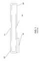
- a heat pipeis a device that can effectively transfer heat from one point to another. It consists of a sealed metal tubular container whose inner surfaces have a capillary wicking material. A fluid flows along the wick structure of the heat pipe.
- FIG. 1shows a heat pipe 101 . It has an inner lining 103 of micron scale wick structures.
- a HPDD 105transfers heat to an end 107 of heat pipe 101 . Liquid at end 107 absorbs the heat, evaporates and moves to a cold end 109 of the heat pipe. The evaporated vapor comes in contact of cold end 109 , condenses and dissipates heat. The condensed liquid moves back to end 107 by gravitation or by capillary action of the inner lining 103 .
- the wick like structure of lining 103provides capillary driving force to return the condensate to end 107 .
- a Heat pipeis useful in transferring heat away from the HPDD when the form factor and other constraints limit dissipation of heat near the HPDD itself. Further, it has the ability to transport heat against gravity with the help of porous capillaries that form the wick.
- Heat pipesexploit liquid-vapor phase change properties. Thus, maximum heat transfer is limited by vapor/liquid nucleation properties. Interface resistance between the metal surface and the liquid layer also limits the maximum heat flow. Heat pipes do not solve the problems of interface resistances at the hot source end and the cold sink end. Interface resistance between the metal surface and the liquid layer also limits the maximum heat flow. It is also not possible to cool multiple hot sources using a single heat pipe. Often these heat pipes contain CFC fluids that are not environment-friendly. The performance of these heat pipes depend on the orientation of the heat pipe structure with respect to the gravitational forces, operating temperatures, and the nature of fluids in the loop. The dependence of performance on orientation restricts the flexible positioning of heat pipes.
- the above-discussed limitations of heat pipeshave made forced fluid cooling an attractive option.
- the forced fluid coolingis based on circulating water through a HPDD. Water carries away heat from the HPDD and dissipates the heat at a sink placed at a distance. The heat is dissipated at the sink using fluid-fluid heat exchangers such as finned radiators with natural or forced convection.
- fluid-fluid heat exchangerssuch as finned radiators with natural or forced convection.
- more than one HPDDcan be cooled in a single loop.
- fluid-fluid heat exchangersincluding condensers, radiators etc.
- the inventionprovides a system for effective removal of heat from a high power density device and dissipating the heat at a distance.
- the system in accordance with the inventionhas a solid-fluid heat exchanger mounted on a high power density device.
- a closed conduit carrying liquid metalpasses through the solid-fluid heat exchanger.
- the liquid metalis circulated in the conduit.
- the liquid metalcarries away the heat generated by the high power density device and dissipates it at a heat exchanger or heat sink provided at a predefined distance away from the device.
- This systemis highly flexible and can be used in different embodiments depending on form factor limitations.
- the same conduit (carrying the liquid metal)can be used for carrying heat away from multiple devices. Multiple pumps arranged in series or parallel arrangements may also be provided.
- Two or more loops (of the conduit)can use a common pump or common solid-fluid heat exchanger.
- a loopcan dissipate heat, which is further carried away by another loop. More and more complex network of loop
- FIG. 1shows the design of a heat pipe existing in prior art
- FIG. 2shows a system for dissipating heat from a high power density device at a distance in accordance with the preferred embodiment of the invention
- FIG. 3shows the principle of an electromagnetic pump provided by the abovementioned system for circulating liquid metal
- FIG. 4shows the use of thermoelectric generator and thermoelectric cooler in the abovementioned system in accordance with an alternate embodiment of the invention
- FIG. 5shows an alternate embodiment that has a fluid-fluid heat exchanger in combination with the heat sink
- FIG. 6Ashows an embodiment that has two electromagnetic pumps in series
- FIG. 6Bshows an embodiment that has two electromagnetic pumps placed in parallel
- FIG. 7shows a complex network that utilizes a combination of multiple primary and secondary closed conduits for removing heat from multiple high power density devices.
- FIG. 2shows a system 200 for dissipating heat from high power density devices.
- System 200comprises a solid-fluid heat exchanger 201 placed adjacent to the high power density device 202 .
- a solid-fluid heat exchanger 201is filled with liquid metal that absorbs the heat from the high power density device 202 .
- a conduit 203passes through solid-fluid heat exchanger 201 that takes away the liquid metal through an end 205 of solid-fluid heat exchanger 201 and brings liquid metal back into solid-fluid heat exchanger 201 through an end 207 .
- Section 203 a of conduit 203carries hot liquid metal away from end 205 of solid-fluid heat exchanger 201 to a heat sink 209 provided at a predefined distance from solid-fluid heat exchanger 201 .
- Heat sink 209releases the heat to the atmosphere.
- the cooled liquid metalis then circulated back to solid-fluid heat exchanger 201 through section 203 b of conduit 203 .
- An electromagnetic pump 211provides the power for circulating the liquid metal in the form of a closed loop.
- system 200provides for the transport and dissipation of heat at a predefined distance away from high power density device 202 . This distance is determined based on the form factor (the configuration and physical arrangement of the various components in and around the high power density device 202 ).
- system 200provides for heat dissipation in the cases where dissipating heat in the proximity of the high power density device 202 is not desirable.
- the heat dissipated by components such as the microprocessor or the power unitis in proximity of components like memory, this heat may lead to permanent loss of data from memory.
- the heat generated by the microprocessor/power unitis dissipated at a position away from components that may get damaged.
- Heat sink 209is constructed of a low thermal resistance material. Examples of such materials include copper and aluminum. Heat sink 209 has a large surface area for effectively dissipating heat to the atmosphere. Heat sink 209 may dissipate heat by natural convection or by forced convection with the use of a fan. A finned structure (as shown in the figures) is sometimes used as a heat sink. In fact, the finned structure may also have liquid metal circulating through its fins. It will be apparent to one skilled in the art that any heat sink structure (used for transferring heat to the atmosphere) may be employed in the system without departing from the scope of the invention.
- Conduit 203is constructed of polymer materials such as teflon or polyurethane. Alternatively, refractory metals such as vanadium or molybdenum may also be used as the material of construction of conduit 203 . Polymers like teflon prove to be good conduit materials as they are inert to most chemicals, provide low resistance to flow of liquids and are resistant to high temperature corrosion.
- Solid-fluid heat exchanger 201comprises a thermally conducting surface closely attached to the high power density device and a housing containing the liquid metal.
- the thermally conducting surfacecould be a thin-film tungsten, nickel layer on the backside of the processor or a discrete surface of tungsten, nickel, anodized aluminum or nickel-coated aluminum soldered to the backside of the chip.
- the housing materialcould be an inert polymer (Teflon, polyurethane, etc.), glass or thermally conductive material such as tungsten, nickel, nickel-coated aluminum, anodized aluminum, nickel-coated copper etc.
- System 200may be used for dissipating heat from a wide variety of devices.
- high power density device 202 of FIG. 2may be a micro scale device like a microelectronic chip, an optoelectronic chip, arrays of hot chips, a laser diode, light emitting diodes (LEDs), an array of LEDs etc.
- High power density device 202may also be a central processing unit of a computer, graphical processor unit or a light bulb.
- System 200also finds application in biological, chemical, or nuclear reactors to dissipate heat generated by these reactors.
- FIG. 3shows the principle of operation of electromagnetic pumps 211 employed in the above-mentioned embodiment.
- Electromagnetic pump 211comprises of a pair of electrode plates 305 placed vertically facing each other. A DC (direct current) voltage is applied across the electrode plates. The DC voltage produces an electric field across electrode plates 305 .
- a pair of permanent magnets 307is arranged facing each other above and below the plane containing electrode plates 305 .
- a tube 309carries liquid metal. The direction of magnetic field generated by the permanent magnets 307 is perpendicular to the direction of electric field provided by the electrode plates 305 .
- An electromagnetic forceacts on the liquid metal causing it to flow in a direction perpendicular to the plane of electric and magnetic fields (as shown by the block arrow in FIG. 3 ).
- DC electromagnetic pumpsas described above
- induction electromagnetic pumps utilizing polyphase induction coilscan be used in cases where physical contact to the liquid metal is undesirable (say, where the liquid metal is corrosive).
- the systemmay need to be provided with electromagnetic interference (EMI) shielding to shield the high power density device from electromagnetic radiations generated by the pump.
- EMIelectromagnetic interference
- the electromagnetic pumpis enclosed within a housing that shields the high power density device.
- This EMI shieldingmay be provided using standard methods such as magnetic shields and EMI shielding tapes.
- magnetic shield 310confines the magnetic field within the pump.
- the magnetic shield 310may be made using high magnetic permeability materials such as steel, nickel, alnico, or permandur or other specially processed materials.
- tube 309is constructed of polymer materials such as Teflon or polyurethane. Teflon has the advantage that it can be easily machined. Alternatively, refractory metals such as tungsten or molybdenum may also be used as the material of construction of tube 309 . Ultra-thin anodized aluminum or nickel-coated aluminum or copper can also be used.
- the liquid metal carried by tube 309is an alloy of gallium and indium.
- Preferred compositionscomprise 65 to 75% by mass gallium and 20 to 25% indium. Materials such as tin, copper, zinc and bismuth may also be present in small percentages.
- One such preferred compositioncomprises 66% gallium, 20% indium, 11% tin, 1% copper, 1% zinc and 1% bismuth.
- Some examples of the commercially available Gain alloysinclude galistan—a concoction popular as a substitute for mercury (Hg) in medical applications, and newmerc.
- the various properties of Ga—In alloymake it desirable liquid metal for use in heat spreaders.
- the Ga—In alloyspans a wide range of temperature with high thermal and electrical conductivities.
- liquid metals having high thermal conductivity, high electrical conductivity and high volumetric heat capacitycan be used.
- liquid metals having high thermal conductivity, high electrical conductivity and high volumetric heat capacitycan be used.
- liquid metals that can be used in an embodiment of the inventioninclude mercury, gallium, sodium potassium eutectic alloy (78% sodium, 22% potassium by mass), bismuth tin alloy (58% bismuth, 42% tin by mass), bismuth lead alloy (55% bismuth, 45% lead) etc.
- Bismuth based alloysare generally used at high temperatures (40 to 140° C.). Pure indium can be used at temperatures above 156° C. (i.e., the melting point of indium).
- FIG. 4shows another embodiment of the invention.
- the embodimentcomprises a thermoelectric generator 401 and a thermoelectric cooler 403 .
- Thermoelectric generator 401is provided for powering electromagnetic pump 211 while thermoelectric cooler 403 is provided for a first stage spot cooling of the high power density device 202 .
- thermoelectric generator 401A face 401 a of thermoelectric generator 401 is placed in contact with section 203 a of conduit 203 .
- Section 203 acarries hot liquid metal to heat sink 209 and has a high temperature.
- a Face 401 b of thermoelectric generator 401is placed in contact with section 203 b of conduit 203 that carries liquid metal (that has been cooled after dissipating heat) away from the heat sink 209 to solid-fluid heat exchanger 201 .
- Face 401 bis thus at a relatively low temperature.
- the temperature difference between the two faces of thermoelectric generator 401is utilized to produce potential difference for powering electromagnetic pump 211 .
- the external power supplyif used, generates heat that has to be removed. This adds to the burden of heat removal from the system.
- potential difference generated by thermoelectric generator 213By using potential difference generated by thermoelectric generator 213 to run electromagnetic pump 211 ; this added burden is done away with.
- Thermoelectric generator 401is comprised of series of p type semiconductor members and n type semiconductor members sandwiched between thermally conducting, electrically-insulating substrates such as oxide-coated silicon wafers, aluminum nitride (AIN) and other thin ceramic wafers.
- Thermoelectric generator 401utilizes the “Seebeck effect” to convert the temperature difference between the hot section 203 a and the cold section 203 b of conduit 203 to electrical energy in the form of a potential difference.
- the voltage generated by thermoelectric generator 401depends on the temperature difference between the sections 203 a and 203 b .
- the performancei.e.
- thermoelectric generator 401the ratio of electrical power to the heat flow into the hot end) of thermoelectric generator 401 is governed by the Seebeck coefficient and thermal conductivity of p and n type semiconductor members used to form the device. Alloys of bismuth (Bi), tellurium (Te), antimony (Sb) and selenium (Se) are the most commonly used materials for manufacturing the semiconductor members of thermoelectric generator 401 for devices operating near room temperature.
- thermoelectric generatorsprovides sufficient power to drive the electromagnetic pumps. This may be illustrated using the following representative example:
- the power requirementis dependent on the distance the fluid needs to move. Typically, this power requirement may range from few milli-watts (say for moving the fluid a distance of 10 cm in case of a laptop), to a watt (say for moving the fluid several meters in a server rack).
- thermoelectric generatori.e. the ratio of electrical power to the heat flow into the hot end
- thermoelectric generatorE is the thermodynamic conversion efficiency
- ⁇ Tis the temperature differential between the hot and cold ends
- T his the temperature of the hot end.
- the value of ⁇is 0.1 for conventional Bi/Sb/Te/Se alloys and Pb/Te/Se alloy materials.
- the typical temperature differential across the two ends of thermoelectric generatorwould be around 15-40 K (i.e., Kelvin).
- ⁇ T30 K
- T h358 K (85° C.) the coefficient of performance ⁇ of the thermoelectric generator comes out to be 0.0084. If the high power density device dissipates 100 W, the electrical power generated by the thermoelectric generator will be 0.84 W, which is sufficient for driving the electromagnetic pump. Of course, better thermoelectric generators can easily double the performance.
- Thermoelectric cooler 403provides a first stage spot cooling of the high power density device 202 .
- Thermoelectric cooler 403utilizes the “Peltier effect” to cool the high power density device 202 .
- the construction of thermoelectric cooler 403is similar to thermoelectric generator 401 .
- a direct current supplied to the thermoelectric cooler 403produces a temperature difference between its two surfaces.
- surface of thermoelectric cooler 403 in contact with high power density device 202is at low temperature (with respect to high power density device 202 ) and surface of thermoelectric cooler in contact with solid-fluid heat exchanger 201 is at higher temperature (with respect to solid-fluid heat exchanger 201 ).
- the amount of cooling provided by thermoelectric cooler 403is a function of the current supplied to it.
- thermoelectric cooler 403is desirable in cases where surface of high power density device 202 has uneven temperature distribution with some regions having temperature much greater than other regions.
- the first stage spot cooling provided by thermoelectric cooler 403helps to make temperature distribution uniform on the surface of high power density device 202 .
- FIG. 5shows yet another embodiment of the invention.
- a fluid-fluid heat exchanger 501is provided in addition to heat sink 209 for dissipating heat from the liquid metal.
- Fluid-fluid heat exchanger 501is provided for cases where additional cooling is required or the rate of cooling of liquid metal needs to be regulated.
- liquid metal coming out through heat sink 209is further cooled using heat exchanger 501 before being circulated back to solid-fluid heat exchanger 201 .
- Fluid-fluid heat exchanger 501makes use of a fluid to absorb the heat from liquid metal. This fluid enters fluid-fluid heat exchanger 501 at one end absorbs heat from liquid metal and comes out through another end. Thus, heat is transferred from liquid metal to the fluid.
- Electromagnetic pump 211provides the power for circulating the liquid metal in form of a closed loop. In this manner, this embodiment provides for the transport and dissipation of heat at multiple positions away from high power density device 202 (shown using dashed lines).
- Fluid-fluid heat exchangersmake use of transfer of heat between two fluids over a common surface.
- use of liquid metal in the inventionmakes it possible to use a heat exchanger for dissipating heat.
- Fluid-fluid heat exchanger 501provides controlled cooling such that the rate of cooling may be regulated depending on requirements. The regulation of cooling rate may be achieved by varying the flow rate or temperature of the fluid in fluid-fluid heat exchanger 501 .
- Fluid-fluid heat exchanger 501can be tubular shell and tube type of heat exchanger with counter or concurrent flow. Heat exchanger 501 can also be a plate type heat exchanger. Fluid-fluid heat exchanger 501 may be replaced by multiple heat exchangers connected in series or parallel. In fact, in place of the combination of heat exchanger 501 and heat sink 209 , heat exchanger 501 alone can be used to dissipate heat. It will be apparent to one skilled in the art that any device that can dissipate/extract heat from liquid metal (e.g. thermoelectric cooler, vapor compression cooler) can replace heat exchanger 501 without departing from the scope of the invention.
- thermoelectric coolervapor compression cooler
- FIG. 6Ashows two electromagnetic pumps 601 and 603 in series that pump liquid metal through conduit 203 .
- Multiple electromagnetic pumps 601 and 603are provided in series configuration where power supplied by one pump is not sufficient to circulate the liquid metal in the form of a closed loop. This may be the case when heat sink 209 is placed at a relatively large distance away from solid-fluid heat exchanger 201 ( e.g. in case of a server rack).
- Two electromagnetic pumps 601 and 603may also be useful where there is sudden loss in the pressure head. In case where the pipes take sharp turns (like in case of laptop joints) a significant drop in the pressure is observed. Due to reasons mentioned above more than two electromagnetic pumps may need to be provided in series.
- FIG. 6Bshows an alternate arrangement where two electromagnetic pumps 605 and 607 arranged in parallel.
- a parallel arrangement of electromagnetic pumpsmay be used in case there are some restrictions on the diameter of the conduit (say, due to form factor limitations).
- the parallel arrangement of pumpsmay also be used where there is a restriction on the size of the pump due to form factor limitations.
- many small pumps in parallelcan be used instead of a one big sized pump.
- FIG. 7shows one such design of a heat dissipating system.
- a solid-fluid heat exchanger 701 placed adjacent to high power density devicecontains liquid metal.
- a conduit 703passes through solid-fluid heat exchanger 701 , carries away hot liquid metal and dissipates heat at a fluid-fluid heat exchanger 705 .
- EM pump 707powers the flow of liquid metal in closed conduit 703 .
- a solid-fluid heat exchanger 709(containing liquid metal) is placed adjacent to a second high power density device.
- a conduit 711carries hot liquid metal away from solid-fluid heat exchanger 709 and dissipates heat at fluid-fluid heat exchanger 705 .
- Two electromagnetic pumps 713 and 715power the flow of liquid metal in closed conduit 711 .
- Electromagnetic pumps 713 and 715are connected in parallel.
- the heat transferred by conduits 703 and 711 to fluid-fluid heat exchanger 705is carried away by the liquid metal in closed conduit 717 . This heat is dissipated at heat sink 719 .
- a pair of electromagnetic pumps 721 and 723power the flow of liquid metal in closed conduit 717 .
- Electromagnetic pumps 721 and 723are connected in series.
- Closed conduits 703 and 709(where liquid metal absorbs heat directly from high power density device) can be seen as primary closed conduits.
- Closed conduit 717can be seen as a secondary closed conduit (where liquid metal absorbs heat dissipated by other closed conduits).
- liquid metal in primary closed conduits 703 and 711dissipates heat at common fluid-fluid heat exchanger 705 .
- This heatis carried away by liquid metal in secondary closed conduit 717 and dissipated at heat sink 719 .
- a networkmay have a plurality of primary and secondary closed conduits that dissipate heat at a common heat exchanger.
- liquid metalalso provides design flexibility.
- design flexibilitydesign of circuits based on electric considerations can be first worked out. Once the electric circuits have been designed, the liquid loops can be designed based on the form factor limitations (due to the circuit components). This approach enables the design of a circuit without taking thermal considerations in account in the first place.
- the systemmay further include a heat spreader positioned adjacent to the high power density device.
- the heat spreadercan include a plurality of cooling chambers containing liquid metal and a plurality of electromagnetic pumps arranged in a configuration so as to circulate the liquid metal in the cooling chambers.
- the various embodiments provided by the inventionmay be used in computational devices such as laptops to dissipate heat generated by the central processing unit.
- the flow of liquid metal in conduits(made of polymers) provides a lot of flexibility to carry away the heat and dissipate it at a heat sink placed at bottom or screen of the laptop.
- the fluid conduitcan be flexed, or bent, allowing the flow of liquid metal to be routed across hinges (in a laptop).
- the networks of primary and secondary closed conduits provided by the inventioncan be used for cooling multiple processors in a server where several discrete high power density devices are located in close physical proximity.
- Primary closed conduitsmay be used to dissipate heat locally while secondary closed conduits can carry away this heat and dissipate it at distant less-populated areas on the board.
Landscapes
- Engineering & Computer Science (AREA)
- Physics & Mathematics (AREA)
- General Engineering & Computer Science (AREA)
- Mechanical Engineering (AREA)
- Thermal Sciences (AREA)
- Power Engineering (AREA)
- Life Sciences & Earth Sciences (AREA)
- Sustainable Development (AREA)
- Condensed Matter Physics & Semiconductors (AREA)
- General Physics & Mathematics (AREA)
- Computer Hardware Design (AREA)
- Microelectronics & Electronic Packaging (AREA)
- Electromagnetism (AREA)
- Cooling Or The Like Of Electrical Apparatus (AREA)
- Cooling Or The Like Of Semiconductors Or Solid State Devices (AREA)
Abstract
Description
Claims (16)
Priority Applications (1)
| Application Number | Priority Date | Filing Date | Title |
|---|---|---|---|
| US10/314,018US6658861B1 (en) | 2002-12-06 | 2002-12-06 | Cooling of high power density devices by electrically conducting fluids |
Applications Claiming Priority (1)
| Application Number | Priority Date | Filing Date | Title |
|---|---|---|---|
| US10/314,018US6658861B1 (en) | 2002-12-06 | 2002-12-06 | Cooling of high power density devices by electrically conducting fluids |
Publications (1)
| Publication Number | Publication Date |
|---|---|
| US6658861B1true US6658861B1 (en) | 2003-12-09 |
Family
ID=29711814
Family Applications (1)
| Application Number | Title | Priority Date | Filing Date |
|---|---|---|---|
| US10/314,018Expired - Fee RelatedUS6658861B1 (en) | 2002-12-06 | 2002-12-06 | Cooling of high power density devices by electrically conducting fluids |
Country Status (1)
| Country | Link |
|---|---|
| US (1) | US6658861B1 (en) |
Cited By (87)
| Publication number | Priority date | Publication date | Assignee | Title |
|---|---|---|---|---|
| US20040068997A1 (en)* | 2000-11-30 | 2004-04-15 | Takaaki Hirooka | Electrode cooler of processing device |
| US20040182088A1 (en)* | 2002-12-06 | 2004-09-23 | Nanocoolers, Inc. | Cooling of electronics by electrically conducting fluids |
| US20040234392A1 (en)* | 2003-05-22 | 2004-11-25 | Nanocoolers Inc. | Magnetohydrodynamic pumps for non-conductive fluids |
| US20040234379A1 (en)* | 2003-05-22 | 2004-11-25 | Nanocoolers, Inc. | Direct current magnetohydrodynamic pump configurations |
| US20050052848A1 (en)* | 2003-09-10 | 2005-03-10 | Hamman Brian A. | Liquid cooling system |
| US20050093140A1 (en)* | 2003-10-25 | 2005-05-05 | Korea Institute Of Science And Technology | Heat spreader, heat sink, heat exchanger and PDP chassis base |
| US20050099775A1 (en)* | 2003-11-12 | 2005-05-12 | Himanshu Pokharna | Pumped liquid cooling for computer systems using liquid metal coolant |
| US20050150537A1 (en)* | 2004-01-13 | 2005-07-14 | Nanocoolers Inc. | Thermoelectric devices |
| US20050150536A1 (en)* | 2004-01-13 | 2005-07-14 | Nanocoolers, Inc. | Method for forming a monolithic thin-film thermoelectric device including complementary thermoelectric materials |
| US20050160752A1 (en)* | 2004-01-23 | 2005-07-28 | Nanocoolers, Inc. | Apparatus and methodology for cooling of high power density devices by electrically conducting fluids |
| US20050189089A1 (en)* | 2004-02-27 | 2005-09-01 | Nanocoolers Inc. | Fluidic apparatus and method for cooling a non-uniformly heated power device |
| US20060033205A1 (en)* | 2004-08-13 | 2006-02-16 | Ioan Sauciuc | Liquid metal thermal interface for an integrated circuit device |
| US20060045755A1 (en)* | 2004-08-24 | 2006-03-02 | Dell Products L.P. | Information handling system including AC electromagnetic pump cooling apparatus |
| US20060073024A1 (en)* | 2004-09-17 | 2006-04-06 | Nanocoolers, Inc. | Series gated secondary loop power supply configuration for electromagnetic pump and integral combination thereof |
| US20060076046A1 (en)* | 2004-10-08 | 2006-04-13 | Nanocoolers, Inc. | Thermoelectric device structure and apparatus incorporating same |
| US20060090474A1 (en)* | 2004-10-29 | 2006-05-04 | Ioan Sauciuc | Method and apparatus for removing heat |
| US20060131002A1 (en)* | 2004-12-17 | 2006-06-22 | Fujikura Ltd. | Heat transfer device |
| US20060137360A1 (en)* | 2004-12-23 | 2006-06-29 | Nanocoolers, Inc. | Thermoelectric configuration employing thermal transfer fluid flow(s) with recuperator |
| US20060137359A1 (en)* | 2004-12-23 | 2006-06-29 | Nanocoolers, Inc. | Counterflow thermoelectric configuration employing thermal transfer fluid in closed cycle |
| US20060144566A1 (en)* | 2004-12-30 | 2006-07-06 | Jensen Kip B | System and method for cooling an integrated circuit device by electromagnetically pumping a fluid |
| US20070035928A1 (en)* | 2003-09-10 | 2007-02-15 | Qnx Cooling Systems Inc. | Cooling system |
| US20070089866A1 (en)* | 2005-10-21 | 2007-04-26 | Sun Microsystems, Inc. | Ferrofluid-cooled heat sink |
| US20070164427A1 (en)* | 2005-12-30 | 2007-07-19 | Ioan Sauciuc | Electromagnetically-actuated micropump for liquid metal alloy enclosed in cavity with flexible sidewalls |
| US20070235180A1 (en)* | 2006-04-06 | 2007-10-11 | Sun Microsystems, Inc. | Multichannel cooling system with magnetohydrodynamic pump |
| WO2005060370A3 (en)* | 2003-12-15 | 2007-12-27 | Nanocoolers Inc | Cooling of high power density devices by electrically conducting fluids |
| US20080008415A1 (en)* | 2005-04-11 | 2008-01-10 | Davis Joseph E | Reduction of mems mirror edge diffraction in a wavelength selective switch using servo-based rotation about multiple non-orthogonal axes |
| US20080010998A1 (en)* | 2006-07-17 | 2008-01-17 | Sun Microsystems, Inc. | Thermal-electric-MHD cooling |
| US7342787B1 (en) | 2004-09-15 | 2008-03-11 | Sun Microsystems, Inc. | Integrated circuit cooling apparatus and method |
| US20080062648A1 (en)* | 2006-09-11 | 2008-03-13 | Gilliland Don A | Heat Sinks for Dissipating a Thermal Load |
| US7436059B1 (en) | 2006-11-17 | 2008-10-14 | Sun Microsystems, Inc. | Thermoelectric cooling device arrays |
| US7475551B2 (en) | 2004-12-23 | 2009-01-13 | Nanocoolers, Inc. | System employing temporal integration of thermoelectric action |
| US20090034202A1 (en)* | 2007-08-03 | 2009-02-05 | Asustek Computer Inc. | Heat-dissipating module |
| US20090126922A1 (en)* | 2007-10-29 | 2009-05-21 | Jan Vetrovec | Heat transfer device |
| US20090279259A1 (en)* | 2008-05-06 | 2009-11-12 | Cripe David W | System and method for proportional cooling with liquid metal |
| US20090279257A1 (en)* | 2008-05-06 | 2009-11-12 | Rockwell Collins, Inc. | System and method for a substrate with internal pumped liquid metal for thermal spreading and cooling |
| US20090317697A1 (en)* | 2008-06-23 | 2009-12-24 | Gm Global Technology Operations, Inc. | Vehicular combination chiller bypass system and method |
| US20100006269A1 (en)* | 2005-12-21 | 2010-01-14 | Sun Microsystems, Inc. | Enhanced heat pipe cooling with mhd fluid flow |
| US7672129B1 (en) | 2006-09-19 | 2010-03-02 | Sun Microsystems, Inc. | Intelligent microchannel cooling |
| US20100066178A1 (en)* | 2008-09-12 | 2010-03-18 | Lower Nathan P | Thin, solid-state mechanism for pumping electrically conductive liquids in a flexible thermal spreader |
| US20100071883A1 (en)* | 2008-09-08 | 2010-03-25 | Jan Vetrovec | Heat transfer device |
| US20100078605A1 (en)* | 2008-09-29 | 2010-04-01 | Lower Nathan P | Glass thick film embedded passive material |
| US20100124022A1 (en)* | 2008-11-14 | 2010-05-20 | Suad Causevic | Thermoelectric cooling apparatus and method for cooling an integrated circuit |
| FR2941562A1 (en)* | 2009-01-29 | 2010-07-30 | Philippe Rhul | Integrated circuit i.e. processor, cooling system for personal computer, has visualization unit arranged opposite to opening formed in heat sink and allowing visualization of coolant during passage of coolant above chip |
| US20110024401A1 (en)* | 2008-03-12 | 2011-02-03 | Trumpf Werkzeugmaschinen Gmbh + Co. Kg | Recovery of Energy from a Laser Machining System |
| US7915527B1 (en) | 2006-08-23 | 2011-03-29 | Rockwell Collins, Inc. | Hermetic seal and hermetic connector reinforcement and repair with low temperature glass coatings |
| US8076185B1 (en) | 2006-08-23 | 2011-12-13 | Rockwell Collins, Inc. | Integrated circuit protection and ruggedization coatings and methods |
| US8084855B2 (en) | 2006-08-23 | 2011-12-27 | Rockwell Collins, Inc. | Integrated circuit tampering protection and reverse engineering prevention coatings and methods |
| CN101764498B (en)* | 2008-12-25 | 2012-02-15 | 中国科学院理化技术研究所 | Electromagnetic pump with internal slide block for driving liquid metal |
| US8166645B2 (en) | 2006-08-23 | 2012-05-01 | Rockwell Collins, Inc. | Method for providing near-hermetically coated, thermally protected integrated circuit assemblies |
| US8205337B2 (en) | 2008-09-12 | 2012-06-26 | Rockwell Collins, Inc. | Fabrication process for a flexible, thin thermal spreader |
| US20120293069A1 (en)* | 2011-05-20 | 2012-11-22 | David Irvin | Task-Lit Cabinet |
| US8363189B2 (en) | 2007-12-18 | 2013-01-29 | Rockwell Collins, Inc. | Alkali silicate glass for displays |
| US20130283253A1 (en)* | 2012-04-23 | 2013-10-24 | Enermax Technology Corporation | Water-cooling thermal dissipating system, thermal dissipatiing method thereof, and firmware updating method thereof |
| US8581108B1 (en) | 2006-08-23 | 2013-11-12 | Rockwell Collins, Inc. | Method for providing near-hermetically coated integrated circuit assemblies |
| US20130314874A1 (en)* | 2012-05-23 | 2013-11-28 | Samsung Electro-Mechanics Co., Ltd. | Heat radiation system for power module |
| US8616266B2 (en) | 2008-09-12 | 2013-12-31 | Rockwell Collins, Inc. | Mechanically compliant thermal spreader with an embedded cooling loop for containing and circulating electrically-conductive liquid |
| US8617913B2 (en) | 2006-08-23 | 2013-12-31 | Rockwell Collins, Inc. | Alkali silicate glass based coating and method for applying |
| US8637980B1 (en) | 2007-12-18 | 2014-01-28 | Rockwell Collins, Inc. | Adhesive applications using alkali silicate glass for electronics |
| US8650886B2 (en) | 2008-09-12 | 2014-02-18 | Rockwell Collins, Inc. | Thermal spreader assembly with flexible liquid cooling loop having rigid tubing sections and flexible tubing sections |
| US9435915B1 (en) | 2012-09-28 | 2016-09-06 | Rockwell Collins, Inc. | Antiglare treatment for glass |
| US9709324B1 (en)* | 2012-11-09 | 2017-07-18 | Rockwell Collins, Inc. | Liquid cooling with parasitic phase-change pumps |
| KR101815947B1 (en) | 2016-06-30 | 2018-01-08 | 조선대학교 산학협력단 | Thermal Control Apparatus using Liquid Metal |
| CN107706165A (en)* | 2017-10-30 | 2018-02-16 | 广东合新材料研究院有限公司 | A kind of liquid metal constant temperature heat abstractor |
| US10122836B2 (en) | 2016-09-28 | 2018-11-06 | Intel Corporation | Magnetic convection cooling for handheld device |
| US10312180B2 (en) | 2012-04-23 | 2019-06-04 | Enermax Technology Corporation | Water-cooling thermal dissipating system and thermal dissipating method |
| US10337770B2 (en) | 2011-07-11 | 2019-07-02 | Gentherm Incorporated | Thermoelectric-based thermal management of electrical devices |
| US10464391B2 (en)* | 2007-05-25 | 2019-11-05 | Gentherm Incorporated | System and method for distributed thermoelectric heating and cooling |
| JP2019201015A (en)* | 2018-05-14 | 2019-11-21 | 大学共同利用機関法人自然科学研究機構 | Laser device |
| US10686232B2 (en) | 2013-01-14 | 2020-06-16 | Gentherm Incorporated | Thermoelectric-based thermal management of electrical devices |
| US10700393B2 (en) | 2014-09-12 | 2020-06-30 | Gentherm Incorporated | Graphite thermoelectric and/or resistive thermal management systems and methods |
| US10720261B2 (en)* | 2016-02-02 | 2020-07-21 | Carnegie Mellon University, A Pennsylvania Non-Profit Corporation | Polymer composite with liquid phase metal inclusions |
| US10784546B2 (en) | 2013-01-30 | 2020-09-22 | Gentherm Incorporated | Thermoelectric-based thermal management system |
| CN111726973A (en)* | 2020-07-22 | 2020-09-29 | 中国科学院大学 | A device and method for realizing the cooling of a large heat flux density device by using a magnetic field |
| CN112984954A (en)* | 2021-01-29 | 2021-06-18 | 东软威特曼生物科技(沈阳)有限公司 | Refrigeration assembly, liquid cooling device and in-vitro diagnostic equipment |
| US11049624B2 (en)* | 2015-12-07 | 2021-06-29 | Ge-Hitachi Nuclear Energy Americas Llc | Nuclear reactor liquid metal coolant backflow control |
| US11069595B2 (en)* | 2018-04-23 | 2021-07-20 | Asia Vital Components Co., Ltd. | Water cooling module |
| US20210302104A1 (en)* | 2020-03-23 | 2021-09-30 | The Government Of The United States Of America, As Represented By The Secretary Of The Navy | Hybrid Loop Heat Pipe with Integrated Magnetically Levitating Bearingless Pump |
| US11152557B2 (en) | 2019-02-20 | 2021-10-19 | Gentherm Incorporated | Thermoelectric module with integrated printed circuit board |
| CN113531102A (en)* | 2021-07-16 | 2021-10-22 | 盐城工学院 | A CST liquid metal circulation loop system with both cooling and power generation functions |
| US11203249B2 (en) | 2009-05-18 | 2021-12-21 | Gentherm Incorporated | Temperature control system with thermoelectric device |
| CN113905588A (en)* | 2021-10-14 | 2022-01-07 | 中国科学院大学 | A device and method for cooling a device with a large heat flux by utilizing a magnetic field and an applied current |
| US11264655B2 (en) | 2009-05-18 | 2022-03-01 | Gentherm Incorporated | Thermal management system including flapper valve to control fluid flow for thermoelectric device |
| CN115451607A (en)* | 2022-09-13 | 2022-12-09 | 中国农业大学 | Thermoelectric system, control method and device for thermoelectric system |
| WO2023046629A1 (en)* | 2021-09-23 | 2023-03-30 | Robert Bosch Gmbh | Temperature-control assembly for a microelectric system |
| US20230127378A1 (en)* | 2020-03-20 | 2023-04-27 | Valeo Systemes Thermiques | Device for thermal regulation of at least one electronic component |
| US11993132B2 (en) | 2018-11-30 | 2024-05-28 | Gentherm Incorporated | Thermoelectric conditioning system and methods |
| US20240377142A1 (en)* | 2021-08-18 | 2024-11-14 | Kohvac Co., Ltd. | Highly Efficient Waste Cold/Warm Heat Recycling Heat Exchange Device |
Citations (4)
| Publication number | Priority date | Publication date | Assignee | Title |
|---|---|---|---|---|
| US3654528A (en)* | 1970-08-03 | 1972-04-04 | Gen Electric | Cooling scheme for a high-current semiconductor device employing electromagnetically-pumped liquid metal for heat and current transfer |
| US4177015A (en)* | 1977-03-23 | 1979-12-04 | United Kingdom Atomic Energy Authority | Electromagnetic pumps |
| US5712448A (en)* | 1996-02-07 | 1998-01-27 | California Institute Of Technology | Cooling device featuring thermoelectric and diamond materials for temperature control of heat-dissipating devices |
| US5991351A (en)* | 1998-09-22 | 1999-11-23 | U.S. Department Of Energy | Method and system to directly produce electrical power within the lithium blanket region of a magnetically confined, deuterium-tritium (DT) fueled, thermonuclear fusion reactor |
- 2002
- 2002-12-06USUS10/314,018patent/US6658861B1/ennot_activeExpired - Fee Related
Patent Citations (4)
| Publication number | Priority date | Publication date | Assignee | Title |
|---|---|---|---|---|
| US3654528A (en)* | 1970-08-03 | 1972-04-04 | Gen Electric | Cooling scheme for a high-current semiconductor device employing electromagnetically-pumped liquid metal for heat and current transfer |
| US4177015A (en)* | 1977-03-23 | 1979-12-04 | United Kingdom Atomic Energy Authority | Electromagnetic pumps |
| US5712448A (en)* | 1996-02-07 | 1998-01-27 | California Institute Of Technology | Cooling device featuring thermoelectric and diamond materials for temperature control of heat-dissipating devices |
| US5991351A (en)* | 1998-09-22 | 1999-11-23 | U.S. Department Of Energy | Method and system to directly produce electrical power within the lithium blanket region of a magnetically confined, deuterium-tritium (DT) fueled, thermonuclear fusion reactor |
Cited By (134)
| Publication number | Priority date | Publication date | Assignee | Title |
|---|---|---|---|---|
| US20040068997A1 (en)* | 2000-11-30 | 2004-04-15 | Takaaki Hirooka | Electrode cooler of processing device |
| US7000416B2 (en)* | 2000-11-30 | 2006-02-21 | Tokyo Electron Limited | Cooling apparatus and plasma processing apparatus having cooling apparatus |
| US20040182088A1 (en)* | 2002-12-06 | 2004-09-23 | Nanocoolers, Inc. | Cooling of electronics by electrically conducting fluids |
| US7131286B2 (en) | 2002-12-06 | 2006-11-07 | Nanocoolers, Inc. | Cooling of electronics by electrically conducting fluids |
| US20040234392A1 (en)* | 2003-05-22 | 2004-11-25 | Nanocoolers Inc. | Magnetohydrodynamic pumps for non-conductive fluids |
| US20040234379A1 (en)* | 2003-05-22 | 2004-11-25 | Nanocoolers, Inc. | Direct current magnetohydrodynamic pump configurations |
| US20060120878A1 (en)* | 2003-05-22 | 2006-06-08 | Nanocoolers, Inc. | Magnetofluiddynamic pumps for non-conductive fluids |
| US7466553B2 (en)* | 2003-09-10 | 2008-12-16 | Qnx Cooling Systems, Inc. | Cooling system |
| US20050052848A1 (en)* | 2003-09-10 | 2005-03-10 | Hamman Brian A. | Liquid cooling system |
| US20070035928A1 (en)* | 2003-09-10 | 2007-02-15 | Qnx Cooling Systems Inc. | Cooling system |
| US7218523B2 (en)* | 2003-09-10 | 2007-05-15 | Qnx Cooling Systems Inc | Liquid cooling system |
| US20050093140A1 (en)* | 2003-10-25 | 2005-05-05 | Korea Institute Of Science And Technology | Heat spreader, heat sink, heat exchanger and PDP chassis base |
| US7176564B2 (en)* | 2003-10-25 | 2007-02-13 | Korea Institute Of Science | Heat spreader, heat sink, heat exchanger and PDP chassis base |
| WO2005051065A3 (en)* | 2003-11-12 | 2005-10-06 | Intel Corp | Pumped liquid cooling for computer systems using liquid metal coolant |
| US20050099775A1 (en)* | 2003-11-12 | 2005-05-12 | Himanshu Pokharna | Pumped liquid cooling for computer systems using liquid metal coolant |
| WO2005060370A3 (en)* | 2003-12-15 | 2007-12-27 | Nanocoolers Inc | Cooling of high power density devices by electrically conducting fluids |
| US20050150536A1 (en)* | 2004-01-13 | 2005-07-14 | Nanocoolers, Inc. | Method for forming a monolithic thin-film thermoelectric device including complementary thermoelectric materials |
| US20050150537A1 (en)* | 2004-01-13 | 2005-07-14 | Nanocoolers Inc. | Thermoelectric devices |
| US20080239672A1 (en)* | 2004-01-23 | 2008-10-02 | Nanocoolers, Inc. | Cooling of High Power Density Devices Using Electrically Conducting Fluids |
| US20050160752A1 (en)* | 2004-01-23 | 2005-07-28 | Nanocoolers, Inc. | Apparatus and methodology for cooling of high power density devices by electrically conducting fluids |
| WO2006025852A3 (en)* | 2004-01-23 | 2007-03-15 | Nanocoolers Inc | Cooling of high power density devices using electrically conducting fluids |
| US20050189089A1 (en)* | 2004-02-27 | 2005-09-01 | Nanocoolers Inc. | Fluidic apparatus and method for cooling a non-uniformly heated power device |
| US20060033205A1 (en)* | 2004-08-13 | 2006-02-16 | Ioan Sauciuc | Liquid metal thermal interface for an integrated circuit device |
| DE112005001952B4 (en)* | 2004-08-13 | 2012-03-29 | Intel Corporation | Liquid metal thermal interface for an integrated switching device |
| US7348665B2 (en) | 2004-08-13 | 2008-03-25 | Intel Corporation | Liquid metal thermal interface for an integrated circuit device |
| WO2006020332A1 (en)* | 2004-08-13 | 2006-02-23 | Intel Corporation | Liquid metal thermal interface for an integrated circuit device |
| KR100895005B1 (en) | 2004-08-13 | 2009-04-27 | 인텔 코오퍼레이션 | Liquid Metal Thermal Interfaces for Integrated Circuit Devices |
| US20060045755A1 (en)* | 2004-08-24 | 2006-03-02 | Dell Products L.P. | Information handling system including AC electromagnetic pump cooling apparatus |
| US7342787B1 (en) | 2004-09-15 | 2008-03-11 | Sun Microsystems, Inc. | Integrated circuit cooling apparatus and method |
| US20060073024A1 (en)* | 2004-09-17 | 2006-04-06 | Nanocoolers, Inc. | Series gated secondary loop power supply configuration for electromagnetic pump and integral combination thereof |
| US20060076046A1 (en)* | 2004-10-08 | 2006-04-13 | Nanocoolers, Inc. | Thermoelectric device structure and apparatus incorporating same |
| US7340904B2 (en)* | 2004-10-29 | 2008-03-11 | Intel Corporation | Method and apparatus for removing heat |
| US20060090474A1 (en)* | 2004-10-29 | 2006-05-04 | Ioan Sauciuc | Method and apparatus for removing heat |
| US7246655B2 (en) | 2004-12-17 | 2007-07-24 | Fujikura Ltd. | Heat transfer device |
| US7540319B2 (en) | 2004-12-17 | 2009-06-02 | Fujikura Ltd. | Heat transfer device |
| US20070235178A1 (en)* | 2004-12-17 | 2007-10-11 | Fujikura Ltd | Heat transfer device |
| US20060131002A1 (en)* | 2004-12-17 | 2006-06-22 | Fujikura Ltd. | Heat transfer device |
| US7293416B2 (en) | 2004-12-23 | 2007-11-13 | Nanocoolers, Inc. | Counterflow thermoelectric configuration employing thermal transfer fluid in closed cycle |
| US7296417B2 (en) | 2004-12-23 | 2007-11-20 | Nanocoolers, Inc. | Thermoelectric configuration employing thermal transfer fluid flow(s) with recuperator |
| US20060137360A1 (en)* | 2004-12-23 | 2006-06-29 | Nanocoolers, Inc. | Thermoelectric configuration employing thermal transfer fluid flow(s) with recuperator |
| US7475551B2 (en) | 2004-12-23 | 2009-01-13 | Nanocoolers, Inc. | System employing temporal integration of thermoelectric action |
| US20060137359A1 (en)* | 2004-12-23 | 2006-06-29 | Nanocoolers, Inc. | Counterflow thermoelectric configuration employing thermal transfer fluid in closed cycle |
| US20060144566A1 (en)* | 2004-12-30 | 2006-07-06 | Jensen Kip B | System and method for cooling an integrated circuit device by electromagnetically pumping a fluid |
| US20080008415A1 (en)* | 2005-04-11 | 2008-01-10 | Davis Joseph E | Reduction of mems mirror edge diffraction in a wavelength selective switch using servo-based rotation about multiple non-orthogonal axes |
| US7621319B2 (en)* | 2005-10-21 | 2009-11-24 | Sun Microsystems, Inc. | Ferrofluid-cooled heat sink |
| US20070089866A1 (en)* | 2005-10-21 | 2007-04-26 | Sun Microsystems, Inc. | Ferrofluid-cooled heat sink |
| US20100006269A1 (en)* | 2005-12-21 | 2010-01-14 | Sun Microsystems, Inc. | Enhanced heat pipe cooling with mhd fluid flow |
| US8336611B2 (en)* | 2005-12-21 | 2012-12-25 | Oracle America, Inc. | Enhanced heat pipe cooling with MHD fluid flow |
| US7764499B2 (en) | 2005-12-30 | 2010-07-27 | Intel Corporation | Electromagnetically-actuated micropump for liquid metal alloy |
| US20070164427A1 (en)* | 2005-12-30 | 2007-07-19 | Ioan Sauciuc | Electromagnetically-actuated micropump for liquid metal alloy enclosed in cavity with flexible sidewalls |
| US20090237884A1 (en)* | 2005-12-30 | 2009-09-24 | Intel Corporation | Electromagnetically-actuated micropump for liquid metal alloy |
| US7539016B2 (en)* | 2005-12-30 | 2009-05-26 | Intel Corporation | Electromagnetically-actuated micropump for liquid metal alloy enclosed in cavity with flexible sidewalls |
| US7870893B2 (en) | 2006-04-06 | 2011-01-18 | Oracle America, Inc. | Multichannel cooling system with magnetohydrodynamic pump |
| US20070235180A1 (en)* | 2006-04-06 | 2007-10-11 | Sun Microsystems, Inc. | Multichannel cooling system with magnetohydrodynamic pump |
| US7562533B2 (en)* | 2006-07-17 | 2009-07-21 | Sun Microsystems, Inc. | Thermal-electric-MHD cooling |
| US20080010998A1 (en)* | 2006-07-17 | 2008-01-17 | Sun Microsystems, Inc. | Thermal-electric-MHD cooling |
| US9196555B1 (en) | 2006-08-23 | 2015-11-24 | Rockwell Collins, Inc. | Integrated circuit protection and ruggedization coatings and methods |
| US7915527B1 (en) | 2006-08-23 | 2011-03-29 | Rockwell Collins, Inc. | Hermetic seal and hermetic connector reinforcement and repair with low temperature glass coatings |
| US8617913B2 (en) | 2006-08-23 | 2013-12-31 | Rockwell Collins, Inc. | Alkali silicate glass based coating and method for applying |
| US8664047B2 (en) | 2006-08-23 | 2014-03-04 | Rockwell Collins, Inc. | Integrated circuit tampering protection and reverse engineering prevention coatings and methods |
| US8581108B1 (en) | 2006-08-23 | 2013-11-12 | Rockwell Collins, Inc. | Method for providing near-hermetically coated integrated circuit assemblies |
| US8935848B1 (en) | 2006-08-23 | 2015-01-20 | Rockwell Collins, Inc. | Method for providing near-hermetically coated integrated circuit assemblies |
| US8166645B2 (en) | 2006-08-23 | 2012-05-01 | Rockwell Collins, Inc. | Method for providing near-hermetically coated, thermally protected integrated circuit assemblies |
| US9565758B2 (en) | 2006-08-23 | 2017-02-07 | Rockwell Collins, Inc. | Alkali silicate glass based coating and method for applying |
| US9197024B1 (en) | 2006-08-23 | 2015-11-24 | Rockwell Collins, Inc. | Method of reinforcing a hermetic seal of a module |
| US8084855B2 (en) | 2006-08-23 | 2011-12-27 | Rockwell Collins, Inc. | Integrated circuit tampering protection and reverse engineering prevention coatings and methods |
| US8076185B1 (en) | 2006-08-23 | 2011-12-13 | Rockwell Collins, Inc. | Integrated circuit protection and ruggedization coatings and methods |
| US7408778B2 (en)* | 2006-09-11 | 2008-08-05 | International Business Machines Corporation | Heat sinks for dissipating a thermal load |
| US20080062648A1 (en)* | 2006-09-11 | 2008-03-13 | Gilliland Don A | Heat Sinks for Dissipating a Thermal Load |
| US7672129B1 (en) | 2006-09-19 | 2010-03-02 | Sun Microsystems, Inc. | Intelligent microchannel cooling |
| US7436059B1 (en) | 2006-11-17 | 2008-10-14 | Sun Microsystems, Inc. | Thermoelectric cooling device arrays |
| US10464391B2 (en)* | 2007-05-25 | 2019-11-05 | Gentherm Incorporated | System and method for distributed thermoelectric heating and cooling |
| US20090034202A1 (en)* | 2007-08-03 | 2009-02-05 | Asustek Computer Inc. | Heat-dissipating module |
| US20090126922A1 (en)* | 2007-10-29 | 2009-05-21 | Jan Vetrovec | Heat transfer device |
| US8363189B2 (en) | 2007-12-18 | 2013-01-29 | Rockwell Collins, Inc. | Alkali silicate glass for displays |
| US8637980B1 (en) | 2007-12-18 | 2014-01-28 | Rockwell Collins, Inc. | Adhesive applications using alkali silicate glass for electronics |
| US10158207B2 (en)* | 2008-03-12 | 2018-12-18 | Trumpf Werkzeugmaschinen Gmbh + Co. Kg | Recovery of energy from a laser machining system |
| US20110024401A1 (en)* | 2008-03-12 | 2011-02-03 | Trumpf Werkzeugmaschinen Gmbh + Co. Kg | Recovery of Energy from a Laser Machining System |
| US20090279257A1 (en)* | 2008-05-06 | 2009-11-12 | Rockwell Collins, Inc. | System and method for a substrate with internal pumped liquid metal for thermal spreading and cooling |
| US8174830B2 (en) | 2008-05-06 | 2012-05-08 | Rockwell Collins, Inc. | System and method for a substrate with internal pumped liquid metal for thermal spreading and cooling |
| US20090279259A1 (en)* | 2008-05-06 | 2009-11-12 | Cripe David W | System and method for proportional cooling with liquid metal |
| US8017872B2 (en) | 2008-05-06 | 2011-09-13 | Rockwell Collins, Inc. | System and method for proportional cooling with liquid metal |
| US8448460B2 (en)* | 2008-06-23 | 2013-05-28 | GM Global Technology Operations LLC | Vehicular combination chiller bypass system and method |
| US20090317697A1 (en)* | 2008-06-23 | 2009-12-24 | Gm Global Technology Operations, Inc. | Vehicular combination chiller bypass system and method |
| US20100071883A1 (en)* | 2008-09-08 | 2010-03-25 | Jan Vetrovec | Heat transfer device |
| US8221089B2 (en) | 2008-09-12 | 2012-07-17 | Rockwell Collins, Inc. | Thin, solid-state mechanism for pumping electrically conductive liquids in a flexible thermal spreader |
| US20100066178A1 (en)* | 2008-09-12 | 2010-03-18 | Lower Nathan P | Thin, solid-state mechanism for pumping electrically conductive liquids in a flexible thermal spreader |
| US8205337B2 (en) | 2008-09-12 | 2012-06-26 | Rockwell Collins, Inc. | Fabrication process for a flexible, thin thermal spreader |
| US8650886B2 (en) | 2008-09-12 | 2014-02-18 | Rockwell Collins, Inc. | Thermal spreader assembly with flexible liquid cooling loop having rigid tubing sections and flexible tubing sections |
| US8616266B2 (en) | 2008-09-12 | 2013-12-31 | Rockwell Collins, Inc. | Mechanically compliant thermal spreader with an embedded cooling loop for containing and circulating electrically-conductive liquid |
| US8119040B2 (en) | 2008-09-29 | 2012-02-21 | Rockwell Collins, Inc. | Glass thick film embedded passive material |
| US8585937B2 (en) | 2008-09-29 | 2013-11-19 | Rockwell Collins, Inc. | Glass thick film embedded passive material |
| US20100078605A1 (en)* | 2008-09-29 | 2010-04-01 | Lower Nathan P | Glass thick film embedded passive material |
| US20100124022A1 (en)* | 2008-11-14 | 2010-05-20 | Suad Causevic | Thermoelectric cooling apparatus and method for cooling an integrated circuit |
| CN101764498B (en)* | 2008-12-25 | 2012-02-15 | 中国科学院理化技术研究所 | Electromagnetic pump with internal slide block for driving liquid metal |
| FR2941562A1 (en)* | 2009-01-29 | 2010-07-30 | Philippe Rhul | Integrated circuit i.e. processor, cooling system for personal computer, has visualization unit arranged opposite to opening formed in heat sink and allowing visualization of coolant during passage of coolant above chip |
| US11264655B2 (en) | 2009-05-18 | 2022-03-01 | Gentherm Incorporated | Thermal management system including flapper valve to control fluid flow for thermoelectric device |
| US11203249B2 (en) | 2009-05-18 | 2021-12-21 | Gentherm Incorporated | Temperature control system with thermoelectric device |
| US9076893B2 (en)* | 2011-05-20 | 2015-07-07 | At&T Intellectual Property I, L.P. | Task-lit cabinet |
| US20120293069A1 (en)* | 2011-05-20 | 2012-11-22 | David Irvin | Task-Lit Cabinet |
| US9534776B2 (en) | 2011-05-20 | 2017-01-03 | At&T Intellectual Property I, L.P. | Task-lit cabinet |
| US10337770B2 (en) | 2011-07-11 | 2019-07-02 | Gentherm Incorporated | Thermoelectric-based thermal management of electrical devices |
| US10312180B2 (en) | 2012-04-23 | 2019-06-04 | Enermax Technology Corporation | Water-cooling thermal dissipating system and thermal dissipating method |
| US20130283253A1 (en)* | 2012-04-23 | 2013-10-24 | Enermax Technology Corporation | Water-cooling thermal dissipating system, thermal dissipatiing method thereof, and firmware updating method thereof |
| US20130314874A1 (en)* | 2012-05-23 | 2013-11-28 | Samsung Electro-Mechanics Co., Ltd. | Heat radiation system for power module |
| US9435915B1 (en) | 2012-09-28 | 2016-09-06 | Rockwell Collins, Inc. | Antiglare treatment for glass |
| US9709324B1 (en)* | 2012-11-09 | 2017-07-18 | Rockwell Collins, Inc. | Liquid cooling with parasitic phase-change pumps |
| US10686232B2 (en) | 2013-01-14 | 2020-06-16 | Gentherm Incorporated | Thermoelectric-based thermal management of electrical devices |
| US10784546B2 (en) | 2013-01-30 | 2020-09-22 | Gentherm Incorporated | Thermoelectric-based thermal management system |
| US10700393B2 (en) | 2014-09-12 | 2020-06-30 | Gentherm Incorporated | Graphite thermoelectric and/or resistive thermal management systems and methods |
| US11798695B2 (en)* | 2015-12-07 | 2023-10-24 | Ge-Hitachi Nuclear Energy Americas Llc | Method of configuring liquid metal-cooled nuclear reactor with backflow electromagnetic pump (EMP) |
| US11049624B2 (en)* | 2015-12-07 | 2021-06-29 | Ge-Hitachi Nuclear Energy Americas Llc | Nuclear reactor liquid metal coolant backflow control |
| US20210287814A1 (en)* | 2015-12-07 | 2021-09-16 | Ge-Hitachi Nuclear Energy Americas Llc | Method of configuring liquid metal-cooled nuclear reactor with backflow electromagnetic pump (emp) |
| US10720261B2 (en)* | 2016-02-02 | 2020-07-21 | Carnegie Mellon University, A Pennsylvania Non-Profit Corporation | Polymer composite with liquid phase metal inclusions |
| KR101815947B1 (en) | 2016-06-30 | 2018-01-08 | 조선대학교 산학협력단 | Thermal Control Apparatus using Liquid Metal |
| US10122836B2 (en) | 2016-09-28 | 2018-11-06 | Intel Corporation | Magnetic convection cooling for handheld device |
| CN107706165B (en)* | 2017-10-30 | 2023-08-15 | 广东西江数据科技有限公司 | Liquid metal constant temperature heat abstractor |
| CN107706165A (en)* | 2017-10-30 | 2018-02-16 | 广东合新材料研究院有限公司 | A kind of liquid metal constant temperature heat abstractor |
| US11069595B2 (en)* | 2018-04-23 | 2021-07-20 | Asia Vital Components Co., Ltd. | Water cooling module |
| JP2019201015A (en)* | 2018-05-14 | 2019-11-21 | 大学共同利用機関法人自然科学研究機構 | Laser device |
| US11993132B2 (en) | 2018-11-30 | 2024-05-28 | Gentherm Incorporated | Thermoelectric conditioning system and methods |
| US11152557B2 (en) | 2019-02-20 | 2021-10-19 | Gentherm Incorporated | Thermoelectric module with integrated printed circuit board |
| US20230127378A1 (en)* | 2020-03-20 | 2023-04-27 | Valeo Systemes Thermiques | Device for thermal regulation of at least one electronic component |
| US20210302104A1 (en)* | 2020-03-23 | 2021-09-30 | The Government Of The United States Of America, As Represented By The Secretary Of The Navy | Hybrid Loop Heat Pipe with Integrated Magnetically Levitating Bearingless Pump |
| US12173965B2 (en)* | 2020-03-23 | 2024-12-24 | The Government Of The United States Of America, As Represented By The Secretary Of The Navy | Hybrid loop heat pipe with integrated magnetically levitating bearingless pump |
| CN111726973A (en)* | 2020-07-22 | 2020-09-29 | 中国科学院大学 | A device and method for realizing the cooling of a large heat flux density device by using a magnetic field |
| CN112984954A (en)* | 2021-01-29 | 2021-06-18 | 东软威特曼生物科技(沈阳)有限公司 | Refrigeration assembly, liquid cooling device and in-vitro diagnostic equipment |
| CN113531102A (en)* | 2021-07-16 | 2021-10-22 | 盐城工学院 | A CST liquid metal circulation loop system with both cooling and power generation functions |
| CN113531102B (en)* | 2021-07-16 | 2023-07-04 | 盐城工学院 | CST liquid metal circulation loop system with cooling and power generation functions |
| US20240377142A1 (en)* | 2021-08-18 | 2024-11-14 | Kohvac Co., Ltd. | Highly Efficient Waste Cold/Warm Heat Recycling Heat Exchange Device |
| WO2023046629A1 (en)* | 2021-09-23 | 2023-03-30 | Robert Bosch Gmbh | Temperature-control assembly for a microelectric system |
| JP2024533680A (en)* | 2021-09-23 | 2024-09-12 | ローベルト ボツシユ ゲゼルシヤフト ミツト ベシユレンクテル ハフツング | Temperature-regulated assemblies for microelectronic systems. |
| CN113905588A (en)* | 2021-10-14 | 2022-01-07 | 中国科学院大学 | A device and method for cooling a device with a large heat flux by utilizing a magnetic field and an applied current |
| CN115451607A (en)* | 2022-09-13 | 2022-12-09 | 中国农业大学 | Thermoelectric system, control method and device for thermoelectric system |
Similar Documents
| Publication | Publication Date | Title |
|---|---|---|
| US6658861B1 (en) | Cooling of high power density devices by electrically conducting fluids | |
| US20050160752A1 (en) | Apparatus and methodology for cooling of high power density devices by electrically conducting fluids | |
| US7131286B2 (en) | Cooling of electronics by electrically conducting fluids | |
| US6708501B1 (en) | Cooling of electronics by electrically conducting fluids | |
| Schmidt | Challenges in electronic cooling: opportunities for enhanced thermal management techniques—microprocessor liquid cooled minichannel heat sink | |
| US7191820B2 (en) | Phase-change heat reservoir device for transient thermal management | |
| JP5644767B2 (en) | Heat transport structure of electronic equipment | |
| EP1148772B1 (en) | Cold plate utilizing fin with evaporating refrigerant | |
| US20100269517A1 (en) | Module for cooling semiconductor device | |
| US8522570B2 (en) | Integrated circuit chip cooling using magnetohydrodynamics and recycled power | |
| US6997241B2 (en) | Phase-change heat reservoir device for transient thermal management | |
| JP2015502054A (en) | Electronic device with cooling action by liquid metal spreader | |
| WO2005060370A2 (en) | Cooling of high power density devices by electrically conducting fluids | |
| US20050121180A1 (en) | Use of graphite foam materials in pumped liquid, two phase cooling, cold plates | |
| Lin et al. | Prospects of confined flow boiling in thermal management of microsystems | |
| US20040052051A1 (en) | Heat sink with heat pipe and base fins | |
| WO2005125297A2 (en) | Cooling electronic devices in computer systems | |
| US20100124022A1 (en) | Thermoelectric cooling apparatus and method for cooling an integrated circuit | |
| US10874034B1 (en) | Pump driven liquid cooling module with tower fins | |
| Deng et al. | Hybrid liquid metal–water cooling system for heat dissipation of high power density microdevices | |
| JP2004071969A (en) | Thermoelectric cooling apparatus | |
| US20070151275A1 (en) | Methods and apparatus for microelectronic cooling using a miniaturized vapor compression system | |
| US20070097637A1 (en) | Heat dissipation device | |
| Galins et al. | Review of cooling solutions for compact electronic devices | |
| JP4391351B2 (en) | Cooling system |
Legal Events
| Date | Code | Title | Description |
|---|---|---|---|
| AS | Assignment | Owner name:NANOCOOLERS, INC., TEXAS Free format text:ASSIGNMENT OF ASSIGNORS INTEREST;ASSIGNORS:GHOSHAL, UTTAM;MINER, ANDREW CARL;REEL/FRAME:013579/0196 Effective date:20021202 | |
| AS | Assignment | Owner name:COMERICA BANK, SUCCESSOR BY MERGER TO COMERICA BAN Free format text:SECURITY AGREEMENT;ASSIGNOR:NANOCOOLERS, INC.;REEL/FRAME:014721/0570 Effective date:20021209 | |
| CC | Certificate of correction | ||
| AS | Assignment | Owner name:COMERICA BANK, SUCCESSOR BY MERGER TO COMERICA BAN Free format text:SECURITY AGREEMENT;ASSIGNOR:NANOCOOLERS, INC.;REEL/FRAME:016470/0927 Effective date:20021209 | |
| FEPP | Fee payment procedure | Free format text:PAT HOLDER NO LONGER CLAIMS SMALL ENTITY STATUS, ENTITY STATUS SET TO UNDISCOUNTED (ORIGINAL EVENT CODE: STOL); ENTITY STATUS OF PATENT OWNER: LARGE ENTITY | |
| FPAY | Fee payment | Year of fee payment:4 | |
| AS | Assignment | Owner name:ZAGORIN O'BRIEN GRAHAM LLP, TEXAS Free format text:ASSIGNMENT OF ASSIGNORS INTEREST;ASSIGNOR:NANOCOOLERS, INC.;REEL/FRAME:023319/0196 Effective date:20091001 Owner name:NANOCOOLERS, INC., TEXAS Free format text:RELEASE BY SECURED PARTY;ASSIGNOR:COMERICA BANK, SUCCESSOR BY MERGER TO COMERICA BANK-CALIFORNIA;REEL/FRAME:023319/0209 Effective date:20090915 | |
| REMI | Maintenance fee reminder mailed | ||
| LAPS | Lapse for failure to pay maintenance fees | ||
| STCH | Information on status: patent discontinuation | Free format text:PATENT EXPIRED DUE TO NONPAYMENT OF MAINTENANCE FEES UNDER 37 CFR 1.362 | |
| FP | Lapsed due to failure to pay maintenance fee | Effective date:20111209 |