US6658692B2 - Small area deep cleaner - Google Patents
Small area deep cleanerDownload PDFInfo
- Publication number
- US6658692B2 US6658692B2US10/064,604US6460402AUS6658692B2US 6658692 B2US6658692 B2US 6658692B2US 6460402 AUS6460402 AUS 6460402AUS 6658692 B2US6658692 B2US 6658692B2
- Authority
- US
- United States
- Prior art keywords
- supply tank
- tank
- liquid
- liquid supply
- cleaning apparatus
- Prior art date
- Legal status (The legal status is an assumption and is not a legal conclusion. Google has not performed a legal analysis and makes no representation as to the accuracy of the status listed.)
- Expired - Lifetime
Links
- 239000007788liquidSubstances0.000claimsabstractdescription140
- 238000011084recoveryMethods0.000claimsabstractdescription57
- 238000004140cleaningMethods0.000claimsdescription48
- 239000012530fluidSubstances0.000claimsdescription11
- XLYOFNOQVPJJNP-UHFFFAOYSA-NwaterSubstancesOXLYOFNOQVPJJNP-UHFFFAOYSA-N0.000claimsdescription7
- 238000004891communicationMethods0.000claimsdescription4
- 230000000295complement effectEffects0.000claimsdescription3
- 239000007921spraySubstances0.000abstractdescription15
- 238000005187foamingMethods0.000abstract1
- 238000001816coolingMethods0.000description14
- 238000003809water extractionMethods0.000description4
- 230000009471actionEffects0.000description3
- 239000006260foamSubstances0.000description3
- 238000003780insertionMethods0.000description3
- 230000037431insertionEffects0.000description3
- 230000008901benefitEffects0.000description2
- 230000005484gravityEffects0.000description2
- 238000005201scrubbingMethods0.000description2
- 230000015572biosynthetic processEffects0.000description1
- 238000010276constructionMethods0.000description1
- 230000000881depressing effectEffects0.000description1
- 230000000994depressogenic effectEffects0.000description1
- 239000013536elastomeric materialSubstances0.000description1
- 239000000284extractSubstances0.000description1
- 238000000605extractionMethods0.000description1
- 230000003993interactionEffects0.000description1
- 230000014759maintenance of locationEffects0.000description1
- 239000000463materialSubstances0.000description1
- 230000013011matingEffects0.000description1
- 230000004048modificationEffects0.000description1
- 238000012986modificationMethods0.000description1
- 238000003825pressingMethods0.000description1
- 230000004044responseEffects0.000description1
- 238000007790scrapingMethods0.000description1
- 238000006748scratchingMethods0.000description1
- 230000002393scratching effectEffects0.000description1
- 229920001169thermoplasticPolymers0.000description1
- 239000004416thermosoftening plasticSubstances0.000description1
- 238000011144upstream manufacturingMethods0.000description1
- 238000013022ventingMethods0.000description1
- 230000000007visual effectEffects0.000description1
- 239000002699waste materialSubstances0.000description1
Images


Classifications
- A—HUMAN NECESSITIES
- A47—FURNITURE; DOMESTIC ARTICLES OR APPLIANCES; COFFEE MILLS; SPICE MILLS; SUCTION CLEANERS IN GENERAL
- A47L—DOMESTIC WASHING OR CLEANING; SUCTION CLEANERS IN GENERAL
- A47L11/00—Machines for cleaning floors, carpets, furniture, walls, or wall coverings
- A47L11/40—Parts or details of machines not provided for in groups A47L11/02 - A47L11/38, or not restricted to one of these groups, e.g. handles, arrangements of switches, skirts, buffers, levers
- A47L11/408—Means for supplying cleaning or surface treating agents
- A47L11/4083—Liquid supply reservoirs; Preparation of the agents, e.g. mixing devices
- A—HUMAN NECESSITIES
- A47—FURNITURE; DOMESTIC ARTICLES OR APPLIANCES; COFFEE MILLS; SPICE MILLS; SUCTION CLEANERS IN GENERAL
- A47L—DOMESTIC WASHING OR CLEANING; SUCTION CLEANERS IN GENERAL
- A47L11/00—Machines for cleaning floors, carpets, furniture, walls, or wall coverings
- A47L11/34—Machines for treating carpets in position by liquid, foam, or vapour, e.g. by steam
- A—HUMAN NECESSITIES
- A47—FURNITURE; DOMESTIC ARTICLES OR APPLIANCES; COFFEE MILLS; SPICE MILLS; SUCTION CLEANERS IN GENERAL
- A47L—DOMESTIC WASHING OR CLEANING; SUCTION CLEANERS IN GENERAL
- A47L11/00—Machines for cleaning floors, carpets, furniture, walls, or wall coverings
- A47L11/40—Parts or details of machines not provided for in groups A47L11/02 - A47L11/38, or not restricted to one of these groups, e.g. handles, arrangements of switches, skirts, buffers, levers
- A47L11/4002—Installations of electric equipment
- A47L11/4008—Arrangements of switches, indicators or the like
- A—HUMAN NECESSITIES
- A47—FURNITURE; DOMESTIC ARTICLES OR APPLIANCES; COFFEE MILLS; SPICE MILLS; SUCTION CLEANERS IN GENERAL
- A47L—DOMESTIC WASHING OR CLEANING; SUCTION CLEANERS IN GENERAL
- A47L11/00—Machines for cleaning floors, carpets, furniture, walls, or wall coverings
- A47L11/40—Parts or details of machines not provided for in groups A47L11/02 - A47L11/38, or not restricted to one of these groups, e.g. handles, arrangements of switches, skirts, buffers, levers
- A47L11/4013—Contaminants collecting devices, i.e. hoppers, tanks or the like
- A—HUMAN NECESSITIES
- A47—FURNITURE; DOMESTIC ARTICLES OR APPLIANCES; COFFEE MILLS; SPICE MILLS; SUCTION CLEANERS IN GENERAL
- A47L—DOMESTIC WASHING OR CLEANING; SUCTION CLEANERS IN GENERAL
- A47L11/00—Machines for cleaning floors, carpets, furniture, walls, or wall coverings
- A47L11/40—Parts or details of machines not provided for in groups A47L11/02 - A47L11/38, or not restricted to one of these groups, e.g. handles, arrangements of switches, skirts, buffers, levers
- A47L11/4036—Parts or details of the surface treating tools
- A47L11/4044—Vacuuming or pick-up tools; Squeegees
- A—HUMAN NECESSITIES
- A47—FURNITURE; DOMESTIC ARTICLES OR APPLIANCES; COFFEE MILLS; SPICE MILLS; SUCTION CLEANERS IN GENERAL
- A47L—DOMESTIC WASHING OR CLEANING; SUCTION CLEANERS IN GENERAL
- A47L11/00—Machines for cleaning floors, carpets, furniture, walls, or wall coverings
- A47L11/40—Parts or details of machines not provided for in groups A47L11/02 - A47L11/38, or not restricted to one of these groups, e.g. handles, arrangements of switches, skirts, buffers, levers
- A47L11/4075—Handles; levers
- A—HUMAN NECESSITIES
- A47—FURNITURE; DOMESTIC ARTICLES OR APPLIANCES; COFFEE MILLS; SPICE MILLS; SUCTION CLEANERS IN GENERAL
- A47L—DOMESTIC WASHING OR CLEANING; SUCTION CLEANERS IN GENERAL
- A47L11/00—Machines for cleaning floors, carpets, furniture, walls, or wall coverings
- A47L11/40—Parts or details of machines not provided for in groups A47L11/02 - A47L11/38, or not restricted to one of these groups, e.g. handles, arrangements of switches, skirts, buffers, levers
- A47L11/408—Means for supplying cleaning or surface treating agents
- A47L11/4088—Supply pumps; Spraying devices; Supply conduits
Definitions
- This inventionrelates to a water extraction cleaning machine and, more particularly, an upright water extraction cleaning machine
- Water extraction cleaning machineshave been used for removing dirt from surfaces such as carpeting, upholstery, drapes and the like.
- the known water extraction cleaning machinescan be in the form of a canister-type unit as disclosed in U.S. Pat. No. 5,237,720 to Blase et al. or an upright unit as disclosed in U.S. Pat. No. 5,500,977 to McAllise et al. and U.S. Pat. No. 4,559,665 to Fitzwater.
- a portable surface cleaning apparatuscomprises a base housing adapted for movement along a surface to be cleaned, an upright handle pivotally mounted to the base module, a liquid dispensing system and a dirty liquid recovery system.
- the liquid dispensing systemcomprises a liquid dispenser associated with the base module for applying liquid to a surface to be cleaned, a liquid supply tank removably mounted to the handle for holding a supply of cleaning liquid and a liquid supply conduit fluidly connected to the liquid supply tank and to the dispenser for supplying liquid to the dispenser.
- the liquid recovery systemcomprises a recovery tank removably mounted on the base housing and having a liquid recovery chamber for holding recovered liquid, a suction nozzle associated with the base housing and adapted to draw dirty liquid from the surface to be cleaned, a working air conduit extending between the recovery chamber and the suction nozzle and a vacuum source in fluid communication with the recovery chamber for generating a flow of working air from the nozzle through the working air conduit and through the recovery chamber to thereby draw dirty liquid from the surface to be cleaned through the nozzle and working air conduit, and into the recovery chamber to thereby recover the dirty liquid from the surface to be cleaned.
- a supply tank mounting assembly on a rear side of the handle and on a front side of the liquid supply tankremovably mounts the liquid supply tank to the rear side of the handle.
- the supply tank mounting assemblycomprises a pair of spaced mounting rails on the rear side the handle and a pair of spaced mounting rails on the liquid supply tank adapted to interface with the handle mounting rails to slidably mount the liquid supply tank to the rear side of the handle.
- the supply tankhas an outlet opening in a lower portion thereof and a cap is removably mounted, typically with threads, in the outlet opening.
- a siphon tubeis mounted to the cap and has a free end distal from the cap. The siphon tube is bent into a shape so that the free end of the siphon tube is adjacent the side wall at a low point in the interior of the tank when the handle is tilted in use.
- a vent holeis preferably provided in the liquid supply tank at an upper portion of the front side thereof for venting air into the supply tank.
- the liquid supply tankhas an elongated shape in a vertical direction when the handle is in an upright position and smoothly conforms to the shape of the handle to an appearance of being integrated therewith.
- the liquid supply tank front sidehas a relatively flat front portion and the handle has a recessed rear wall complementary to the flat front portion of the liquid supply tank.
- the relatively flat front portion of the supply tank front sideis received in the recessed rear wall of the handle.
- the rear wall of the liquid supply tankhas a concave outward shape.
- the front facehas a fill opening at a central portion thereof whereby the supply tank can be filled while oriented horizontally.
- a fill cap/measureis removably mounted, typically with threads, in the fill opening.
- the fill cap/measurehas on an interior end a cavity that has a predetermined capacity related to a predetermined volume in the liquid supply tank whereby the fill cap/measure serves as a measuring container for cleaning solution that is added to the predetermined volume of clean water in the liquid supply tank to form a solution of a desired concentration in the liquid supply tank.
- the liquid supply tankhas measuring indicia on the tank to indicate when the tank has been filled to the predetermined volume.
- the measuring indiciacomprises a mark on an upper portion of a wall of the liquid supply tank to indicate the predetermined volume when the tank is in an upright position.
- the measuring indiciafurther comprises a mark in a vertical direction along a side wall of the liquid supply tank near the front side thereof to indicate the predetermined volume when the tank is in a horizontal fill position.
- the supply tankis at least partially translucent or transparent so that the level of the liquid in the tank can be observed by an operator.
- the liquid supply tankhas an elongated shape in a vertical direction when the handle is in an upright position and smoothly conforms to the shape of the handle to an appearance of being integrated therewith.
- the recovery tankhas an outlet opening for passage of air directly to the atmosphere and a filter mounted in the outlet opening.
- a tank ventis mounted in the recovery tank outlet opening and the filter is mounted in the tank vent.
- the tank ventis preferably snap-fit into the outlet opening.
- the recovery tankfurther includes an inlet opening and the working air conduit is fluidly connected to the inlet opening.
- the recovery tankfurther has a diverter in alignment with the inlet opening for breaking up the flow of dirty liquid entering the liquid recovery chamber.
- the inlet openingis at an upper portion of the recovery tank and a top wall of the recovery tank is shaped to direct the flow of dirty liquid downwardly in the liquid recovery chamber.
- the recovery tankfurther has a baffle that is positioned below the inlet opening and diverter.
- the baffleincludes a plurality of openings for passage of dirty liquid and air therethrough.
- the working air conduitis formed at least in part integrally with the recovery tank.
- a cord wrapis mounted on the handle assembly for wrapping the cord in a loop
- an electrical cordis mounted to the handle adjacent the cord wrap and connected to the vacuum source
- a strain relief collaris mounted on the electrical cord at the handle and aligned with the cord wrap so that the electrical cord is relatively straight and unstressed between the handle and the cord wrap.
- the strain reliefis formed of an elastomeric material.
- the vacuum sourceincludes an inlet conduit connected to the working air conduit and a grill in the inlet conduit to prevent debris from entering the vacuum source. Further, a flow-restricting baffle upstream from the grill is in the inlet conduit.
- the base housingincluding a cooling air inlet on a lower surface thereof in communication with the vacuum motor.
- the base housingfurther comprises a cooling air outlet on a lower portion thereof.
- FIG. 1is a perspective view of a small area deep cleaner according to the invention.
- FIG. 1Ais a side view of the small area deep cleaner of FIG. 1 with the upright handle in a tilted-back position.
- FIG. 2is an exploded perspective view of an upright handle of the small area deep cleaner of FIG. 1 .
- FIG. 3is an exploded perspective view of a rear face of a liquid supply tank of the small area deep cleaner of FIGS. 1 and 2.
- FIG. 3Ais a side view of the liquid supply tank of FIG. 3 .
- FIG. 3Bis a front view of the liquid supply tank of FIGS. 3 and 3A.
- FIG. 3Cis a cross-sectional view taken through line 3 C— 3 C of FIG. 3 B.
- FIG. 4is an exploded perspective view of a floor-traveling head portion of the small area deep cleaner of FIG. 1 .
- FIG. 5is a plan view of a baffle from the small area deep cleaner of FIG. 4 .
- FIG. 6is a plan view of the floor-traveling head of the small area deep cleaner of FIGS. 1-5.
- FIG. 7is a cross-sectional view taken through lines 7 — 7 of FIG. 6 .
- FIG. 8is a cross-sectional view taken through lines 8 — 8 of FIG. 6 .
- FIG. 9is a perspective view of a recovery tank from the small area deep cleaner of FIGS. 1-8.
- FIG. 9Ais a plan view of the recovery collection tank of FIG. 9 .
- FIG. 10is a perspective view of a tank vent of the small area deep cleaner of FIGS. 1-9.
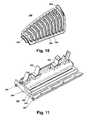
- FIG. 11is a perspective view of a bare floor tool for the small area deep cleaner of FIGS. 1-10.
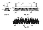
- FIG. 12is a perspective view of a brush for the small area deep cleaner of FIGS. 1-11.
- FIG. 13is an end view of the brush of FIG. 12 .
- FIG. 14is a front view of the brush of FIGS. 12-13.
- FIG. 15is a bottom view of the brush of FIGS. 12 - 14 .
- a small area deep cleaner 10according to the invention comprises an upright handle 100 pivotally connected to a floor-traveling head 200 .
- Small area deep cleaner 10is rollingly supported on a surface by wheels 272 and nozzle 260 .
- Upright handle 100includes an upright handle housing 102 comprising front and rear shells 110 , 120 , a handgrip 130 , an upper handle tube 134 , and a liquid supply tank 140 .
- Upper cord wrap 136generally projects from handgrip 130
- lower cord wrap 112generally projects from housing 102 .
- Floor-traveling head 200includes a base housing 210 and a recovery tank assembly 240 .
- Recovery tank assembly 240is secured to base housing 210 by latches 214 .
- the upright handle 100comprises front shell 110 , rear shell 120 , and handgrip 130 comprising first and second handgrip pieces 131 , 132 .
- Handgrip 130is connected to the front and rear shells 110 , 120 by upper handle tube 134 , with upper handle tube 134 received between each of front and rear shells 110 , 120 and first and second handgrip pieces 131 , 132 , and secured thereto to form the upright handle assembly 100 in combination with the liquid supply tank 140 .
- Handgrip 130further comprises a clean solution feed trigger 170 pivotally mounted to and captured between first and second handgrip pieces 131 , 132 , and upper cord wrap 136 pivotally mounted to second handgrip piece 132 .
- Trigger 170is adapted to operatively contact the upper end of an upper clean solution feed rod 172 slidably carried within upper handle tube 134 and handgrip 130 .
- Rod 172includes a number of transverse slot apertures 173 adapted to receive a fastener (not shown) during assembly of the handgrip 130 and upper handle tube 134 .
- Upper cord wrap 136is pivotally mounted to second handgrip piece 132 , and includes a detent (not shown) for aligning upper cord wrap 136 in a vertical orientation (see FIG. 1) for holding a coil of electrical cord 118 in cooperation with fixed lower cord wrap 112 molded into front and rear shells 110 , 120 .
- Upright handle housing 102includes front and rear shells 110 , 120 , each molded to include internal structural features adapted to hold and/or guide working elements of the cleaner 10 .
- Lower cord wrap 112is composed of a portion extending from a side of each of the front and rear shells 110 , 120 that together form lower cord wrap 112 when shells 110 , 120 are assembled.
- a strain relief projection 114is positioned on a side of shells 110 , 120 below and in alignment with lower cord wrap 112 . Strain relief projection 114 is adapted to receive an electrical cord strain relief 124 for aligning it with upper and lower cord wraps 136 , 112 . In assembled form, electrical cord 178 is thus aligned for storage on cord wraps 136 , 112 .
- Rear shell 120includes a power switch aperture 116 opening to a rear face thereof, and a pair of parallel liquid supply tank guide rails 118 arranged above a liquid supply tank support shelf 121 (see FIG. 1A) on a rear face of rear shell 120 .
- An opening 122is provided in the liquid supply tank support shelf 121 .
- upright handle 100further comprises an upper clean solution receiver 160 , a lower clean solution receiver 162 , a flow valve switch 164 , a flow valve O-ring 166 , a flow valve spring 168 , and a flow valve washer 169 .
- the upright handle 100further comprises a lower clean solution feed rod 174 for operatively connecting upper clean solution feed rod 172 and flow valve switch 164 .
- liquid supply tank 140is generally hollow and of a blow-molded construction.
- the tank 140comprises an integrally formed handle 142 , a liquid supply tank fill opening 144 , and a liquid supply tank feed opening 150 .
- the liquid supply tank fill opening 144is located in a central portion on a front surface 157 of the tank 150 and is internally threaded for threaded receipt and retention of a liquid supply tank fill cap/measure 146 with conventional external threads that match the internal threads on the fill opening 144 .
- Intersecting horizontal and vertical indicia fill lines 143 at right angles to each otherare printed on a side surface of the liquid supply tank 140 between the handle 142 and the tank feed opening 150 and provide a visual indication to a user of a predetermined tank volume in either an upright or horizontal orientation.
- Fill cap/measure 146has an internal cavity 147 which has a measured volume for a user to measure a predetermined amount of cleaning solution for addition to the liquid supply tank 140 in a predetermined proportion to the predetermined tank volume of liquid supply tank 140 as represented by the fill lines 143 .
- the liquid supply tankis molded from a thermoplastic that is at least partially transparent or translucent so that a user can tell when the liquid volume in the tank reaches the fill lines 143 .
- a liquid supply tank fill cap O-ring 148resides between the fill cap/measure 146 and tank 140 to provide a fluid tight seal.
- the tank feed opening 150protrudes from the bottom of tank 140 and is externally threaded.
- a liquid supply tank feed valve 152is sized to be received in the tank feed opening 150 and is held in place by a liquid supply tank feed valve retainer ring 154 .
- Liquid supply tank feed valve 152includes a projection 159 housing a spring-biased plug 155 .
- a ribbed resilient seal 153surrounds projection 159 , ribs 149 forming an annular seal about the circumference of projection 159 when inserted in a corresponding well in upper clean solution receiver 160 .
- the well of upper clean solution receiver 160further includes a centered upstanding pin for pushing plug 155 against its spring-bias, thereby opening valve 152 .
- a siphon tube 151is fluidly connected to liquid supply tank feed valve 152 .
- Siphon tube 151is adapted to extend toward a bottom portion of a rear face 158 of tank 140 for fluidly connecting that portion of tank 140 through valve 152 to projection 159 .
- Front surface 157 of tank 140further includes a vent hole 141 located between the handle 142 and tank fill opening 144 .
- a pair of opposed parallel liquid supply tank mounting rails 156are molded into the front surface 157 of tank 140 and extend from the area above solution tank feed opening 150 to the liquid supply tank fill opening 144 .
- the floor-traveling head 200comprises a base housing 210 , a housing cover 220 , a motor/impeller assembly 230 , a recovery tank assembly 240 , and nozzle assembly 260 .
- the motor/impeller assembly 230comprises a motor 232 having a drive shaft 233 , motor cooling impeller 232 A, motor mounts 308 , 309 , 310 , and an impeller 234 carried within a two-piece impeller shell 236 .
- Impeller shell 236includes an intake port 238 having ribs 302 across its opening, and an output port 239 .
- Intake port 238is provided with an intake port gasket 300 , which includes a resilient restricting flap 304 for covering a portion of intake port 238 .
- Output port 239is provided with an output port gasket 306 .
- the recovery tank assembly 240comprises a tank upper shell 242 and a tank lower shell 256 , a baffle 254 , a suction channel cap 248 , and a tank vent 290 .
- the shells 242 , 256define a tank cavity 258 .
- the upper shell 242comprises a generally smooth outer surface, except for a longitudinal suction channel 246 on an upper surface of the upper shell 242 (see FIG. 4 ).
- An upper end of the suction channel 246terminates in a vertical passage 251 passing through an extended portion of the material of the upper shell 242 through an outlet opening 253 but not into the tank cavity 258 .
- a second aperture 252 located on a rear portion of the upper shell 242passes into the cavity 258 (see FIG. 8 ).
- a V-shaped diverter 249is integrally formed on an inside surface of the tank upper shell 242 in axial alignment with the second aperture 252 .
- a tank vent opening 250is adapted to receive the tank vent 290 that provides further passage into the tank cavity 258 .
- the tank vent 290comprises multiple slots 292 to permit the passage of air, and is molded to closely fit within the tank vent opening 250 and conform to the outer curvature of the tank upper shell 242 .
- One edge of the tank vent 290is resilient and includes a finger tab 294 (see FIGS. 9 - 10 ).
- An opposing edge of the tank vent 290includes a recessed extension 296 that cooperates with the opposing resilient edge to hold the tank vent 290 within the opening 250 .
- the nozzle assembly 260comprises a nozzle 262 , a see-through nozzle lens 264 , a spray bar 266 , a brush 268 , and a nozzle gasket 269 .
- the spray bar 266includes a spray bar cover 267 , the spray bar 266 and cover 267 being secured to an inside surface of the front face of the nozzle 262 .
- the spray bar 266comprises a single inlet and a plurality of outlets evenly spaced across its length.
- the inletis fluidly connected with the upper clean solution receiver 160 via a conduit (not shown).
- the brush 268removably clips in place on the underside of the nozzle 262 with sufficient clearance such that the brush 268 floats freely in the nozzle 262 .
- the brush 268comprises a vertical alignment device 268 B extending axially from either end of the brush body 268 A (see FIG. 12 ).
- a resilient clip 261is located inboard of the alignment device 268 B on each end of the brush body 268 A.
- a plurality of bristle bundles 268 Cextend axially from the brush body 268 A in opposition to the resilient clip 261 and alignment device 268 B.
- the bristle bundles 268 Care arranged in rows transverse to a longitudinal axis of brush 268 .
- Each row of bristle bundles 268 Cdescribes an angle with the vertical centerline of brush 268 (see FIG. 13 ), with the transverse rows alternating from one side to the other of the longitudinal centerline.
- the rows of bristle bundles 268 Care aligned vertically at the center of the brush body 268 A and are canted outwardly at increasing angles from the center to the lateral sides of the brush.
- the small area deep cleaner 10is assembled in the following fashion.
- the upper clean solution feed rod 172is inserted in the upper handle tube 134 so that a portion projects above the upper end of the handle tube 134 .
- the first and second hand grip pieces 131 , 132are then assembled over the upper end of the upper handle tube 134 and the upper cleaner solution feed rod 172 , enclosing the tube 134 and rod 172 .
- the clean solution feed trigger 170is inserted between the first and second hand grip pieces 131 , 132 and pivotally carried on the interior of the handgrip 130 so that one end of the trigger 170 is aligned against the upper end of the upper clean solution feed rod 172 .
- the upper cord wrap 136is assembled to the second handgrip piece 132 .
- the assemblycomprising the hand grip 130 and tube 134 is then centrally aligned on the rear shell 120 of the upright handle 100 .
- the assemblycomprising the upper clean solution receiver 160 , lower clean solution receiver 162 , flow valve switch 164 , flow valve O-ring 166 , flow valve spring 168 and flow valve washer 169 have also been assembled on a lower portion of the rear shell 120 , with the lower clean solution feed rod 174 aligned between the switch 164 and the upper rod 172 .
- a clean solution feed tube 350is attached to an outlet portion on the clean solution receiver 160 and is threaded through the interior of the rear shell 120 toward the bottom of the shell 120 for eventual passage to the floor-traveling head 200 .
- An electrical cord strain relief 124is oriented axially in a slot 104 in the shells 110 , 120 with a electrical cord 178 extending from the exterior of the shell 120 through the strain relief 124 into the interior of the rear shell 120 , and electrically connected with a power switch 180 .
- An interconnect harness 179is connected to the power switch 180 at one end and is threaded through to the lower portion of the rear shell 120 for eventual passage to the floor-traveling head 200 .
- the front shell 110is then secured over the front of the rear shell 120 , the front shell 110 and rear shell 120 mating so as to hold in place those components installed in the rear shell 120 .
- the front shell 110 and the rear shell 120are typically injection-molded with an internal configuration adapted to receive and hold the various components in place.
- the liquid supply tank 140is assembled by the placement of the fill cap/measure 146 and fill cap O-ring 148 into the fill opening 144 , and the placement of the feed valve 152 with siphon tube 151 into the feed opening 150 , the feed valve 152 being held in place by the retainer ring 156 .
- the liquid supply tank 140as assembled, is then ready to be mounted on the rear face of the rear shell 120 by lowering the tank 140 against the rear face of the rear shell 120 and sliding the liquid supply tank mounting rails 156 within liquid supply tank guide rails 118 provided on the rear face of the rear shell 120 .
- the assembled upright handle 100further comprises, on a lower portion of the rear shell 120 , a pair of inwardly directed rimmed collars 126 .
- the center of each of these collarsincludes an aperture 127 for receipt of a pin axle 274 for wheels 272 for the small area deep cleaner 10 .
- Each collar 126further comprises an arcuate aperture 128 for the passage of the clean solution feed tube 350 on the one hand, and the interconnect harness 179 on the other hand, from the rear shell 120 into the floor-traveling head 200 of the small area deep cleaner 10 .
- the floor-traveling head 200is assembled in the following fashion.
- the motor/impeller assembly 230is assembled by the attachment of the motor 232 to the rear half of the impeller shell 236 , allowing the motor shaft 233 to pass through a central opening in the rear half of the impeller shell 236 .
- the impeller 234is secured to the motor shaft 233 via a threaded insert molded into impeller 234 .
- Bushing 312provides a seal at motor shaft 233 on rear half of impeller shell 236 .
- the front half of the impeller shell 236is then mated with the rear half, enclosing the impeller 234 , and with the appropriate seals/bushings in place creating a water-tight enclosure.
- Base housing 210includes a cooling air inlet 325 for passage of cooling air into base housing 210 , through motor vent apertures 223 and into the motor/impeller assembly 230 , and a motor exhaust 324 for exhaust of cooling air from motor/impeller assembly 230 beneath base housing 210 .
- Motor cooling impeller 232 Acan thus draw cooling air into motor/impeller assembly 230 through cooling air inlet 325 of base housing 210 and motor vent apertures 223 , and exhaust cooling air through motor exhaust 324 to exhaust cooling air from base housing 210 .
- a detent lever 216 , detent spring 217 , and detent lever pin 218are then assembled to a rear portion of the base housing 210 .
- Bushings 270are then installed over the collars 126 of the upright handle 100 and wheels 272 are secured to the handle 100 by a pin axle 274 and clip 275 through the apertures 127 , the completed upright handle assembly 100 is then mated with the base housing 210 by the placement of each bushing 70 and collar 126 arrangement in semi-circular recesses 212 on the exterior sides of the base housing 210 .
- the clean solution feed tube and electrical cordare now available to the interior of the base housing 210 through the arcuate apertures 128 , and are run in channels 322 provided in the molded base housing 210 to their respective destinations, the interconnect harness 179 being run to the motor 232 and the clean solution feed tube being run to the front portion of the base housing 210 for attachment to the nozzle assembly 260 .
- the housing cover 220is then attached to the base housing 210 , the cover 220 comprising among other elements semi-circular recesses 224 on its exterior sides, aligned with the semi-circular recesses of the base housing 220 , to encompass the upper half of the collar 126 and bushing 270 of the upright handle 100 , thereby pivotally mounting the upright handle 100 to the floor-traveling head 200 .
- Upright handle 100is maintained in a vertical orientation with respect to floor-traveling head 200 by the action of detent lever 216 preventing upright handle 100 rotating in a rearward direction, and by the abutment of upright handle stops 129 to base housing stops 329 in a frontward direction. Upright handle stops 129 and base housing stops 329 further prevent upright handle 100 from rotating forward and bearing against recovery tank assembly 240 .
- the nozzle assembly 260is then assembled to the front portion of the base housing 210 , the nozzle 262 carrying on an underside thereof the spray bar 266 , fluidly connected to clean solution feed tube 350 , spray bar cover 267 , and the brush 268 .
- the nozzle lens 264is mounted to the front of the nozzle 262 , forming a portion of a suction channel between the nozzle lens 264 and the nozzle 262 .
- a front portion of the base housing 210 and the rear portion of the nozzle 262are molded with a channel for the passage of the clean solution feed tube 350 to the spray bar 266 .
- the brush 268fastens in a removable fashion to the underside of the nozzle 262 by the insertion of integrally molded resilient clips 261 through apertures 263 provided in the nozzle 262 .
- the nozzle gasket 269nests in a recess formed in an upper portion of the assembled nozzle 262 and nozzle lens 264 .
- the base housing 210further comprises a pair of opposing fold-over latches 214 with over-center links 215 for aligning with catches 318 on the sides of the tank assembly 240 for securing the tank assembly 240 to the base housing 210 .
- the floor-traveling head 200is now ready to receive the removable recovery tank assembly 240 .
- Assembly of the recovery tank assembly 240comprises securing the baffle 254 into the upper shell 242 and the insertion of the tank vent 290 into the tank vent opening 250 .
- the tank vent 290normally carries a foam type filter for the trapping of incidental spray introduced into the tank and to reduce noise generated by the unit.
- the upper shell 242is then assembled to the tank lower shell 256 in a sealed fashion to create a water-tight receptacle.
- the tank lower shell 256is molded and contoured 320 to nest within the base housing 210 .
- the upper shell 242is further completed by the attachment of the suction channel cap 248 over the suction channel 246 .
- the suction channel 246 created between the upper shell 242 and the suction channel cap 248aligns with the suction channel formed between the nozzle 262 and nozzle lens 264 , the nozzle gasket 269 providing for a continuous water-tight channel.
- the recovery tank assembly 240further comprises, in the upper shell 242 , a vertical passage 251 contiguous with the suction channel 246 . With the recovery tank assembly 240 secured in place on the floor-traveling head 200 , vertical passage 251 aligns with the intake port 238 and the impeller shell 236 .
- Recovery tank assembly 240is secured to base housing 210 by latches 214 , which provide a downward force on recovery tank assembly 240 to create a water-tight seal by intake port gasket 300 between vertical passage 251 and intake port 238 , and further create a water-tight seal by output port gasket 306 between second aperture 252 and output port 239 .
- Intake port gasket 300includes flap 304 which reduces the area of intake port 238 , which controls the volume of air flow into the motor/impeller assembly 230 and thereby minimizes the amount of air introduced into the solution.
- the intake port 238comprises a conduit with a number of ribs 302 for limiting the debris contained in the flow that passes into the impeller shell 236 .
- the suction channel 246is therefore fluidly connected with the intake port 238 of the impeller shell 236 .
- the upper shell 242further comprises a second aperture 252 on a rear portion thereof providing a fluid connection between the tank cavity 258 and the output port 239 of the impeller shell 236 with interposed gasket 306 for providing a fluid seal between output port 239 and second aperture 252 .
- the vertical passage 251is fluidly isolated from the tank cavity 258 , but, when connected to the intake port 238 , is fluidly connected to the tank cavity 258 through the impeller shell 236 and output port 239 .
- the motor/impeller assembly 230is activated by the provision of power to the motor 232 through the power switch 180 , creating a suction force at the intake port 238 of the impeller shell 236 .
- This suction forceis fluidly connected from the intake port 238 through the suction channel 246 to the portion of the nozzle 262 adjacent to the surface to be cleaned.
- the circuit of dirty fluid flowruns from the opening of the suction nozzle 262 to the tank cavity 258 through the suction channel 246 , vertical passage 251 , intake port 238 , impeller shell 236 , output port 239 , and through the second aperture 252 on the rear of the upper shell 242 .
- the flow of dirty solutioncan be observed by the user through the see-through nozzle lens 264 .
- Dirty wateris deposited in the tank cavity 258 , with waste air vented from the tank cavity 258 through tank vent 290 .
- the motor 232has an impeller 232 A that draws cooling air through the cooling air inlet 325 located on the bottom of the base housing 210 .
- Cleaning solutionis provided to the surface to be cleaned by depressing the cleaning solution feed trigger 170 , which, by action of the upper and lower clean solution feed rods 172 , 174 activates the clean solution flow valve switch 164 .
- the upper clean solution receiver 160receives the projection 159 of the liquid supply tank feed valve 152 through an opening 122 provided in the in the rear shell 120 of the upright handle 100 .
- Clean solution contained in the liquid supply tank 150is gravity-fed into the clean solution receiver 160 , 162 , where it is held until the flow valve switch 164 is depressed.
- the clean solutionflows from the clean solution receiver 160 , 162 through a clean solution feed tube 350 to the spray bar 266 where it continues to flow by gravity to the surface to be cleaned.
- the suction force provided at the nozzle 262then extracts the solution, now considered a dirty solution, through the suction channel 246 and into the impeller shell 236 .
- the dirty solutionis then expelled from the impeller shell 236 through the output port 239 and into the upper shell 242 and diverter 249 of the recovery tank assembly 240 .
- the dirty solutionis directed downwardly into the tank cavity 258 by impinging upon the inner face of the upper shell 242 .
- the dirty solutiondrops out of the fluid stream as it slows, while the remaining, clean air in the fluid stream is vented from the recovery tank assembly 240 through the tank vent 290 .
- the foam-type filter carried by the tank vent 290as stated above, captures incident water spray, preventing it from passing through the tank vent 290 and reducing noise from the motor assembly.
- the baffle 254serves the function of dispersing the flow of dirty solution into the recovery tank assembly 240 . By dispersing the flow, the baffle 254 prevents the force of the expelled dirty solution from splashing the solution already collected in the tank, reducing the likelihood of excess splatter beyond the capacity of the foam filter, and reducing the formation of foam in the dirty solution.
- the openings in the baffle 254are graduated, with smaller slots 255 adjacent the second aperture 252 serving to more effectively disperse the force of the solution expelled into the tank, and larger openings 257 , remote from the second aperture 252 but adjacent the vent opening 250 .
- Baffle 254includes outer edge contours 314 for closely conforming to the interior of upper shell 242 , and recesses 316 for attaching baffle 254 to upper shell 242 at lugs 317 .
- the dirty solution in the tankis disposed of by inverting the recovery tank assembly 240 and pouring the dirty solution out of the second aperture 252 .
- the dirty solutionis disposed of by removing the tank vent 290 and pouring the dirty solution out through the tank vent opening 250 .
- the larger baffle openings 257 adjacent the tank vent opening 250make it easier to empty the recovery tank assembly 240 .
- FIGS. 6-8illustrate the relationship of the recovery tank assembly 240 with respect to the base housing 210 , and in the cross-sectional view of FIG. 7 illustrates the suction channel 246 passing from the nozzle 262 through the suction channel 246 of the upper shell 242 and into the intake port 238 of the impeller shell 236 .
- FIG. 8then illustrates the relationship of the output port 239 of the impeller shell 236 to the second aperture 252 in the upper shell 242 above the baffle 254 .
- the arrowsindicate the direction of airflow in both FIGS. 7-8.
- FIG. 9provides another view of the tank assembly 240 showing the relationship of the baffle 254 and tank vent 290 , as well as the second aperture 252 in the upper shell 242 which fluidly connects with the output port 239 of the impeller shell 236 .
- Diverter 249is also shown in its relationship to the second aperture 252 here and in FIG. 9A, a plan view of the upper shell 242 .
- the tank vent 290shown in detail in FIG. 10, is removed from the tank vent opening 250 by applying pressure to the finger tab 294 , pulling the edge of the vent 290 away from the edge of the tank opening 250 and relieving the friction between the vent 290 and the opening 250 .
- the vent 290can then be removed by grasping the finger tab 294 and rotating the vent 290 about the opposing extension 296 .
- An additional feature of the small area deep cleaner 10 according to the inventionis a bare floor tool 280 shown in perspective in FIG. 11 .
- the bare floor tool 280is generally rectangular in plan view and removably clips in place on the underside of the nozzle 262 , in place of the brush 268 .
- the bare floor tool 280includes a pair of resilient molded clips 288 for insertion in the same apertures 263 of the nozzle 262 that receive the clips 261 of the brush 268 .
- the bare floor tool 280comprises a reinforced sponge 284 , parallel to and between a squeegee 282 located along the front edge, and a plurality of bristles 285 located along a back edge.
- the bare floor tool 280is configured so that, when installed in place of the brush 268 , the suction nozzle 262 will be aligned with the slit apertures 287 , and the spray bar 266 will direct cleaning solution to the surface to be cleaned through the central opening 286 .
- the leading edge of the floor-traveling head 200will therefore have a squeegee 282 against the floor, followed by the slit apertures 287 with nozzle 262 therein, spray bar 266 within the central opening 286 , the sponge 284 somewhat compressed against the floor, and the brush 285 in operative contact with the floor.
- the brush 285provides a scrubbing action on the bare floor, the sponge 284 serving the purpose of even fluid distribution and some degree of scrubbing, and the squeegee 282 scraping water from the surface to be extracted by the nozzle 262 .
Landscapes
- Cleaning By Liquid Or Steam (AREA)
- Cleaning In General (AREA)
- Nozzles For Electric Vacuum Cleaners (AREA)
Abstract
Description
Claims (32)
Priority Applications (5)
| Application Number | Priority Date | Filing Date | Title |
|---|---|---|---|
| US10/064,604US6658692B2 (en) | 2000-01-14 | 2002-09-12 | Small area deep cleaner |
| US10/605,412US20040111821A1 (en) | 2000-01-14 | 2003-09-29 | Small area deep cleaner |
| US10/710,791US20050050671A1 (en) | 2000-01-14 | 2004-08-03 | Extraction cleaner exhaust ducting |
| US10/904,205US7475451B2 (en) | 2000-01-14 | 2004-10-28 | Extraction with air venting |
| US12/339,954US7845045B2 (en) | 2000-01-14 | 2008-12-19 | Extraction with air venting |
Applications Claiming Priority (3)
| Application Number | Priority Date | Filing Date | Title |
|---|---|---|---|
| US17638000P | 2000-01-14 | 2000-01-14 | |
| US09/755,724US6467122B2 (en) | 2000-01-14 | 2001-01-05 | Deep cleaner with tool mount |
| US10/064,604US6658692B2 (en) | 2000-01-14 | 2002-09-12 | Small area deep cleaner |
Related Parent Applications (1)
| Application Number | Title | Priority Date | Filing Date |
|---|---|---|---|
| US09/755,724DivisionUS6467122B2 (en) | 2000-01-14 | 2001-01-05 | Deep cleaner with tool mount |
Related Child Applications (1)
| Application Number | Title | Priority Date | Filing Date |
|---|---|---|---|
| US10/605,412DivisionUS20040111821A1 (en) | 2000-01-14 | 2003-09-29 | Small area deep cleaner |
Publications (2)
| Publication Number | Publication Date |
|---|---|
| US20030005545A1 US20030005545A1 (en) | 2003-01-09 |
| US6658692B2true US6658692B2 (en) | 2003-12-09 |
Family
ID=26872174
Family Applications (5)
| Application Number | Title | Priority Date | Filing Date |
|---|---|---|---|
| US09/755,724Expired - LifetimeUS6467122B2 (en) | 2000-01-14 | 2001-01-05 | Deep cleaner with tool mount |
| US10/064,604Expired - LifetimeUS6658692B2 (en) | 2000-01-14 | 2002-09-12 | Small area deep cleaner |
| US10/605,412AbandonedUS20040111821A1 (en) | 2000-01-14 | 2003-09-29 | Small area deep cleaner |
| US10/904,205Expired - Fee RelatedUS7475451B2 (en) | 2000-01-14 | 2004-10-28 | Extraction with air venting |
| US12/339,954Expired - Fee RelatedUS7845045B2 (en) | 2000-01-14 | 2008-12-19 | Extraction with air venting |
Family Applications Before (1)
| Application Number | Title | Priority Date | Filing Date |
|---|---|---|---|
| US09/755,724Expired - LifetimeUS6467122B2 (en) | 2000-01-14 | 2001-01-05 | Deep cleaner with tool mount |
Family Applications After (3)
| Application Number | Title | Priority Date | Filing Date |
|---|---|---|---|
| US10/605,412AbandonedUS20040111821A1 (en) | 2000-01-14 | 2003-09-29 | Small area deep cleaner |
| US10/904,205Expired - Fee RelatedUS7475451B2 (en) | 2000-01-14 | 2004-10-28 | Extraction with air venting |
| US12/339,954Expired - Fee RelatedUS7845045B2 (en) | 2000-01-14 | 2008-12-19 | Extraction with air venting |
Country Status (1)
| Country | Link |
|---|---|
| US (5) | US6467122B2 (en) |
Cited By (69)
| Publication number | Priority date | Publication date | Assignee | Title |
|---|---|---|---|---|
| US20030226230A1 (en)* | 2002-06-07 | 2003-12-11 | The Hoover Company | Liquid distribution system for a cleaning machine |
| US20040134019A1 (en)* | 2003-01-09 | 2004-07-15 | Royal Appliance Mfg. Co. | Clutchless self-propelled vacuum cleaner and nozzle height adjustment mechanism therefor |
| US20040187250A1 (en)* | 2003-03-25 | 2004-09-30 | Leonatti John A. | Constant head device for a cleaning machine |
| US20050015918A1 (en)* | 2003-07-22 | 2005-01-27 | Royal Appliance Mfg. Co. | Brushless dc drive mechanism for seld propelled aplicance |
| US6944903B2 (en) | 1999-06-11 | 2005-09-20 | Gavney Jr James A | Dentition cleaning device and system |
| US20050217062A1 (en)* | 2001-07-30 | 2005-10-06 | Tennant Company | Air purging of a liquid dispensing system of a surface cleaner |
| US20050283939A1 (en)* | 2004-06-25 | 2005-12-29 | The Hoover Company | Handle assembly for a cleaning apparatus |
| USD520195S1 (en)* | 2005-03-15 | 2006-05-02 | Bissell Homecare, Inc. | Extractor base portion |
| US20060096165A1 (en)* | 2004-06-25 | 2006-05-11 | Oryxe Energy International, Inc. | Novel hydrocarbon fuel additives and fuel formulations exhibiting improved combustion properties |
| US7047589B2 (en) | 1999-06-11 | 2006-05-23 | Gavney Jr James A | Dentition cleaning device and system |
| US7069615B2 (en) | 1999-06-11 | 2006-07-04 | Gavney Jr James A | Squeegee device and system |
| USD530473S1 (en)* | 2005-03-16 | 2006-10-17 | Bissell Homecare, Inc. | Vacuum cleaner handle portion |
| USD533076S1 (en)* | 2003-10-27 | 2006-12-05 | Innovation And Design, Inc. | Suction cup mounted shower container |
| US7155308B2 (en) | 2000-01-24 | 2006-12-26 | Irobot Corporation | Robot obstacle detection system |
| US7172658B2 (en)* | 2001-07-30 | 2007-02-06 | Tennant Company | Cleaning liquid dispensing in a mobile hard surface cleaner |
| US7181799B2 (en) | 1999-06-11 | 2007-02-27 | Eegee, Llc | Oral-care device and system |
| US7332890B2 (en) | 2004-01-21 | 2008-02-19 | Irobot Corporation | Autonomous robot auto-docking and energy management systems and methods |
| US20080042466A1 (en)* | 2003-09-17 | 2008-02-21 | Roll-Rite Llc | Trailer cover system |
| CN100384359C (en)* | 2006-01-25 | 2008-04-30 | 泰怡凯电器(苏州)有限公司 | Wet type cleaning device |
| US7389156B2 (en) | 2005-02-18 | 2008-06-17 | Irobot Corporation | Autonomous surface cleaning robot for wet and dry cleaning |
| US7434288B2 (en) | 2000-09-19 | 2008-10-14 | Gavney Jr James A | Oral care device with multi-structural contact elements |
| GB2456207A (en)* | 2008-01-04 | 2009-07-08 | Bissell Homecare Inc | Effervescent detergent dispenser kit and method |
| US7562411B2 (en) | 1999-06-11 | 2009-07-21 | Gavney Jr James A | Oral-care device and system |
| US7620476B2 (en) | 2005-02-18 | 2009-11-17 | Irobot Corporation | Autonomous surface cleaning robot for dry cleaning |
| US7706917B1 (en) | 2004-07-07 | 2010-04-27 | Irobot Corporation | Celestial navigation system for an autonomous robot |
| US7743448B2 (en) | 1999-06-11 | 2010-06-29 | Gavney Jr James A | Device and system with moving squeegee fields |
| US7761954B2 (en) | 2005-02-18 | 2010-07-27 | Irobot Corporation | Autonomous surface cleaning robot for wet and dry cleaning |
| US20100223741A1 (en)* | 2006-02-17 | 2010-09-09 | Bsh Bosch Und Siemens Hausgerate Gmbh | Cleaning Device for a Component of a Household Washer-Dryer |
| US7814603B2 (en) | 1999-06-11 | 2010-10-19 | Gavney Jr James A | Powered toothbrush with polishing elements |
| US7814604B2 (en) | 2000-09-19 | 2010-10-19 | Gavney Jr James A | Device with multi-structural contact elements |
| US7877833B2 (en) | 1999-06-11 | 2011-02-01 | Gavney Jr James A | Oral-care device and system |
| US20110079248A1 (en)* | 2009-10-06 | 2011-04-07 | Bissell Homecare, Inc. | Extraction with Temporary Suction Interrupt |
| EP2329754A2 (en) | 2009-12-03 | 2011-06-08 | Bissell Homecare, Inc. | Low moisture extraction deep cleaning |
| US7975339B2 (en) | 1999-06-11 | 2011-07-12 | Gavney Jr James A | Aquatic scrubber |
| US8028365B2 (en) | 2003-09-02 | 2011-10-04 | Tennant Company | Hard and soft floor cleaning tool and machine |
| US8141194B2 (en) | 2002-11-09 | 2012-03-27 | Gavney Jr James A | Absorbent structures with integrated contact elements |
| US8239992B2 (en) | 2007-05-09 | 2012-08-14 | Irobot Corporation | Compact autonomous coverage robot |
| US8253368B2 (en) | 2004-01-28 | 2012-08-28 | Irobot Corporation | Debris sensor for cleaning apparatus |
| EP2494902A2 (en) | 2011-03-02 | 2012-09-05 | Bissell Homecare, Inc. | Floor cleaner with stowable handle |
| US8276233B2 (en) | 1999-06-11 | 2012-10-02 | Gavney Jr James A | Multi-directional wiping elements and device using the same |
| US8276231B2 (en) | 1999-06-11 | 2012-10-02 | Gavney Jr James A | Oral-care device and system |
| US8368339B2 (en) | 2001-01-24 | 2013-02-05 | Irobot Corporation | Robot confinement |
| US8374721B2 (en) | 2005-12-02 | 2013-02-12 | Irobot Corporation | Robot system |
| US8380350B2 (en) | 2005-12-02 | 2013-02-19 | Irobot Corporation | Autonomous coverage robot navigation system |
| US8386081B2 (en) | 2002-09-13 | 2013-02-26 | Irobot Corporation | Navigational control system for a robotic device |
| US8382906B2 (en) | 2005-02-18 | 2013-02-26 | Irobot Corporation | Autonomous surface cleaning robot for wet cleaning |
| US8396592B2 (en) | 2001-06-12 | 2013-03-12 | Irobot Corporation | Method and system for multi-mode coverage for an autonomous robot |
| US8412377B2 (en) | 2000-01-24 | 2013-04-02 | Irobot Corporation | Obstacle following sensor scheme for a mobile robot |
| US8417383B2 (en) | 2006-05-31 | 2013-04-09 | Irobot Corporation | Detecting robot stasis |
| US8418303B2 (en) | 2006-05-19 | 2013-04-16 | Irobot Corporation | Cleaning robot roller processing |
| US8428778B2 (en) | 2002-09-13 | 2013-04-23 | Irobot Corporation | Navigational control system for a robotic device |
| US8463438B2 (en) | 2001-06-12 | 2013-06-11 | Irobot Corporation | Method and system for multi-mode coverage for an autonomous robot |
| US8474090B2 (en) | 2002-01-03 | 2013-07-02 | Irobot Corporation | Autonomous floor-cleaning robot |
| US8515578B2 (en) | 2002-09-13 | 2013-08-20 | Irobot Corporation | Navigational control system for a robotic device |
| EP2636354A2 (en) | 2012-03-09 | 2013-09-11 | Bissell Homecare, Inc. | Surface cleaning apparatus |
| US8584305B2 (en) | 2005-12-02 | 2013-11-19 | Irobot Corporation | Modular robot |
| US8600553B2 (en) | 2005-12-02 | 2013-12-03 | Irobot Corporation | Coverage robot mobility |
| EP2671493A2 (en) | 2012-06-04 | 2013-12-11 | Bissell Homecare, Inc. | Surface cleaning apparatus |
| US8780342B2 (en) | 2004-03-29 | 2014-07-15 | Irobot Corporation | Methods and apparatus for position estimation using reflected light sources |
| US8788092B2 (en) | 2000-01-24 | 2014-07-22 | Irobot Corporation | Obstacle following sensor scheme for a mobile robot |
| US8800107B2 (en) | 2010-02-16 | 2014-08-12 | Irobot Corporation | Vacuum brush |
| US8930023B2 (en) | 2009-11-06 | 2015-01-06 | Irobot Corporation | Localization by learning of wave-signal distributions |
| US8972052B2 (en) | 2004-07-07 | 2015-03-03 | Irobot Corporation | Celestial navigation system for an autonomous vehicle |
| US9008835B2 (en) | 2004-06-24 | 2015-04-14 | Irobot Corporation | Remote control scheduler and method for autonomous robotic device |
| US9320398B2 (en) | 2005-12-02 | 2016-04-26 | Irobot Corporation | Autonomous coverage robots |
| US11786094B2 (en) | 2020-07-07 | 2023-10-17 | Bissell Inc. | Surface cleaning apparatus |
| USD1017156S1 (en) | 2022-05-09 | 2024-03-05 | Dupray Ventures Inc. | Cleaner |
| US12096905B2 (en) | 2021-03-17 | 2024-09-24 | Dupray Ventures Inc. | Spot cleaner apparatus |
| US12239267B2 (en) | 2019-07-02 | 2025-03-04 | Mark Jeffery Giarritta | Four-direction scrubbing carpet shampooer |
Families Citing this family (50)
| Publication number | Priority date | Publication date | Assignee | Title |
|---|---|---|---|---|
| US6467122B2 (en) | 2000-01-14 | 2002-10-22 | Bissell Homecare, Inc. | Deep cleaner with tool mount |
| US6536071B2 (en)* | 2001-01-12 | 2003-03-25 | Royal Appliance Mfg. Co. | Tank mounting of carpet extractor |
| US6832409B2 (en)* | 2001-09-18 | 2004-12-21 | The Hoover Company | Wet/dry floor cleaning unit and method of cleaning |
| US7200893B2 (en)* | 2003-01-10 | 2007-04-10 | The Hoover Company | Brush assembly for a floor cleaning unit |
| US6953299B2 (en)* | 2003-01-16 | 2005-10-11 | The Clorox Company | Cleaning implement with interchangeable tool heads |
| US7356875B2 (en)* | 2003-03-11 | 2008-04-15 | Healthy Gain Investments Ltd | Air exhaust system for a cleaning machine |
| AU2004227911B2 (en)* | 2003-03-31 | 2009-11-26 | Bissell Inc. | Unattended spot cleaning apparatus |
| EP1658003B1 (en) | 2003-08-22 | 2011-07-13 | Bissell Homecare, Inc. | Wet/dry bare floor cleaner |
| US7823250B2 (en)* | 2003-08-26 | 2010-11-02 | Bissell Homecare, Inc. | Bare floor cleaner |
| US7225501B2 (en)* | 2003-09-17 | 2007-06-05 | The Hoover Company | Brush assembly for a cleaning device |
| US7159271B2 (en) | 2003-09-29 | 2007-01-09 | Electrolux Home Care Products Ltd. | Wet extractor cleaning device fluid tank arrangement |
| DE102004019155A1 (en)* | 2004-04-21 | 2005-11-10 | Robert Bosch Gmbh | Dust collector for a hand tool |
| CA2510660A1 (en)* | 2004-06-25 | 2005-12-25 | The Hoover Company | Handle assembly for a cleaning apparatus |
| USD545012S1 (en)* | 2004-09-08 | 2007-06-19 | The Hoover Company | Base for an upright extractor |
| USD519695S1 (en)* | 2004-10-07 | 2006-04-25 | Oreck Holdings, Llc | Carpet cleaner |
| US7757341B2 (en)* | 2004-12-22 | 2010-07-20 | Diversey, Inc. | Spot removal device |
| US7793385B2 (en) | 2005-01-07 | 2010-09-14 | Bissell Homecare Inc. | Extraction cleaning with air flow drying |
| US7958652B2 (en) | 2005-01-07 | 2011-06-14 | Bissell Homecare Inc. | Extraction cleaning with plenum and air outlets facilitating air flow drying |
| GB2424174B (en)* | 2005-03-18 | 2008-07-23 | Bissell Homecare Inc | Spot Cleaning Apparatus |
| CN2788728Y (en)* | 2005-03-29 | 2006-06-21 | 苏州索发电机有限公司 | Water filtering vacuum suction dust cleaner with umbrella-shape baffle plate |
| JP4779013B2 (en) | 2005-05-05 | 2011-09-21 | テナント カンパニー | Floor cleaning and polishing machine |
| EP2271243B1 (en)* | 2008-04-03 | 2015-01-21 | Techtronic Floor Care Technology Limited | Floor cleaning device with multiple agitators |
| US8161595B1 (en) | 2008-04-17 | 2012-04-24 | Wilson Javan E | Vacuum cleaner with scrubbers |
| US20100212688A1 (en)* | 2009-02-26 | 2010-08-26 | Goff Sean K | Fluid heating system for a cleaning device |
| ES2900664T3 (en) | 2010-02-15 | 2022-03-17 | Bissell Inc | Upright deep cleaner |
| EP4085813B1 (en)* | 2010-04-29 | 2025-05-28 | Diversey, Inc. | Floor cleaning tool |
| AU2013219229B2 (en)* | 2012-08-29 | 2017-07-13 | Bissell Inc. | Extraction cleaner with heat transfer |
| CA2907984A1 (en)* | 2013-03-27 | 2014-10-02 | Hansa Medical Products, Inc. | Septal perforation prosthesis |
| WO2015126445A1 (en)* | 2014-02-18 | 2015-08-27 | Roth Circle II, LLC | Grill oiling apparatus |
| US20150245758A1 (en)* | 2014-02-28 | 2015-09-03 | Rug Doctor, LLC | Liquid Extraction Cleaning Device |
| US9307881B2 (en) | 2014-03-12 | 2016-04-12 | Techtronic Industries Co. Ltd. | Extractor cleaning machine |
| USD780390S1 (en) | 2014-10-20 | 2017-02-28 | The Kirby Company/Scott Fetzer Company | Handle for a surface-treatment apparatus |
| USD789632S1 (en) | 2014-10-20 | 2017-06-13 | The Kirby Company/Scott Fetzer Company | Surface-treatment apparatus |
| USD762992S1 (en) | 2014-10-20 | 2016-08-09 | The Kirby Company / Scott Fetzer Company | Textile with pattern |
| US9713411B2 (en) | 2014-10-20 | 2017-07-25 | The Kirby Company / Scott Fetzer Company | Surface-treatment apparatus and head unit |
| CN105662289B (en)* | 2016-01-27 | 2018-02-13 | 宁波德昌电机制造有限公司 | A kind of carpet cleaner structure |
| CN109330473A (en)* | 2016-08-04 | 2019-02-15 | 深圳瑞科时尚电子有限公司 | Cistern assembly |
| US10512383B2 (en)* | 2017-11-30 | 2019-12-24 | Bissell Homecare, Inc. | Surface cleaning apparatus |
| CN111712168B (en) | 2017-12-21 | 2021-11-02 | 创科地板护理技术有限公司 | Support structure for a surface cleaning apparatus |
| CN107969994A (en)* | 2017-12-31 | 2018-05-01 | 苏州金丝鸟机器人科技有限公司 | The security protection clean robot that a kind of hydrocone type supplies water |
| US11284767B2 (en) | 2018-08-29 | 2022-03-29 | Bissell Inc. | Surface cleaning apparatus |
| CN109349967B (en)* | 2018-12-06 | 2020-11-06 | 马鞍山市志诚科技有限公司 | Novel household cleaning robot |
| EP3897330B1 (en) | 2018-12-21 | 2023-09-06 | Tennant Company | Sweeper/scrubber system capable of handling large debris |
| CN111358379B (en)* | 2018-12-26 | 2022-03-04 | 苏州尚腾科技制造有限公司 | Water tank assembly and floor washing machine with same |
| FR3092981B1 (en)* | 2019-02-21 | 2021-02-19 | Seb Sa | Stick vacuum cleaner with a main body formed from a first and a second half-shells |
| IT201900007003A1 (en)* | 2019-05-20 | 2020-11-20 | 4Cleanpro S R L | EQUIPMENT FOR THE TREATMENT OF FLOORS |
| CN110786789A (en)* | 2019-11-01 | 2020-02-14 | 江苏师范大学 | An easily disassembled washing machine sewage tank |
| CN111110120B (en)* | 2020-02-13 | 2021-07-13 | 德清县杰创机械有限公司 | Household carpet cleaning and maintaining device |
| CN114376471B (en)* | 2021-09-01 | 2023-04-25 | 北京顺造科技有限公司 | Filters for surface cleaning equipment, recycling storage and surface cleaning equipment |
| AU2023424754A1 (en) | 2023-01-20 | 2025-07-31 | Sharkninja Operating Llc | Extraction cleaner |
Citations (13)
| Publication number | Priority date | Publication date | Assignee | Title |
|---|---|---|---|---|
| US2246111A (en) | 1938-08-02 | 1941-06-17 | French Renovating Company | Scrubbing machine for floors and floor coverings |
| US3029461A (en)* | 1960-06-30 | 1962-04-17 | Bissell Inc | Combination vacuum cleaner and floor scrubber |
| US3101505A (en) | 1961-07-18 | 1963-08-27 | Electrolux Corp | Surface treating machine |
| US3540072A (en) | 1964-08-03 | 1970-11-17 | Sunbeam Corp | Floor conditioner |
| US4559665A (en) | 1984-03-02 | 1985-12-24 | Regina Corporation | Indicator nozzle for cleaning devices |
| US4724573A (en)* | 1986-01-14 | 1988-02-16 | Knud E. Westergaard | Machine for cleaning carpets |
| US5287587A (en)* | 1991-09-10 | 1994-02-22 | Yonkers Robert A | Self-contained, compact vacuum/extractor |
| US5406673A (en)* | 1994-01-14 | 1995-04-18 | The Hoover Company | Tank carry handle and securement latch |
| US5500977A (en) | 1994-01-14 | 1996-03-26 | The Hoover Company | Upright carpet extractor |
| US6065182A (en)* | 1996-06-07 | 2000-05-23 | Royal Appliance Mfg. Co. | Cordless wet mop and vacuum assembly |
| US6154917A (en) | 1999-01-08 | 2000-12-05 | Royal Appliance Mfg. Co. | Carpet extractor housing |
| US6158081A (en) | 1995-11-06 | 2000-12-12 | Bissell Homecare, Inc. | Water extraction cleaning machine with variable solution mixing valve |
| US6167587B1 (en) | 1997-07-09 | 2001-01-02 | Bissell Homecare, Inc. | Upright extraction cleaning machine |
Family Cites Families (19)
| Publication number | Priority date | Publication date | Assignee | Title |
|---|---|---|---|---|
| US1849663A (en)* | 1928-12-26 | 1932-03-15 | Walter S Finnell | Vacuum floor mopper |
| US2099172A (en)* | 1933-06-30 | 1937-11-16 | Apex Electrical Mfg Co | Suction sweeper |
| US2333829A (en)* | 1941-03-01 | 1943-11-09 | Merrill H Terry | Scrubbing attachment for portable vacuum-type floor sweepers |
| US2622254A (en)* | 1947-11-18 | 1952-12-23 | Mendelson Charles | Portable and manually operable apparatus for the cleaning and/or finishing of carpeted or uncarpeted floors |
| US2635278A (en)* | 1951-08-18 | 1953-04-21 | William J Belknap | Floor drying apparatus containing baffle structure for separation of entrained liquid |
| US3064300A (en)* | 1960-04-13 | 1962-11-20 | Signal Mfg Co | Floor cleaning apparatus |
| US3188681A (en)* | 1962-01-24 | 1965-06-15 | Sunbeam Corp | Vacuum cleaner |
| DE3002422C2 (en)* | 1980-01-24 | 1982-12-23 | Leopold 7962 Wolfegg Knestele | Carpet cleaning device |
| US4413372A (en)* | 1981-11-12 | 1983-11-08 | Shop-Vac Corporation | Shoe attachment for wet/dry electric vacuum cleaner |
| US5237720A (en)* | 1990-05-04 | 1993-08-24 | Bissell Inc. | Carpet extractor with bucket caddy |
| FR2715053B1 (en)* | 1994-01-14 | 1996-03-15 | Famulus | Cleaning device by spreading cleaning liquid and by suction of used liquid. |
| US5455982A (en)* | 1994-04-22 | 1995-10-10 | Advance Machine Company | Hard and soft floor surface cleaning apparatus |
| US5608946A (en)* | 1995-05-15 | 1997-03-11 | The Hoover Company | Control cable and wiring arrangement for a vaccum cleaner |
| US6156081A (en) | 1997-04-11 | 2000-12-05 | Combustion Technologies, Inc. | Combustion catalyst |
| JP3609582B2 (en)* | 1997-06-23 | 2005-01-12 | 三洋電機株式会社 | Electric vacuum cleaner |
| GB2331919B (en)* | 1997-12-05 | 2002-05-08 | Bissell Inc | Handheld extraction cleaner |
| US6079080A (en)* | 1998-10-05 | 2000-06-27 | Castex Incorporated | Upright floor cleaner |
| US6247202B1 (en)* | 1999-06-04 | 2001-06-19 | The Hoover Company | Carpet extractor fluid supply system |
| US6467122B2 (en)* | 2000-01-14 | 2002-10-22 | Bissell Homecare, Inc. | Deep cleaner with tool mount |
- 2001
- 2001-01-05USUS09/755,724patent/US6467122B2/ennot_activeExpired - Lifetime
- 2002
- 2002-09-12USUS10/064,604patent/US6658692B2/ennot_activeExpired - Lifetime
- 2003
- 2003-09-29USUS10/605,412patent/US20040111821A1/ennot_activeAbandoned
- 2004
- 2004-10-28USUS10/904,205patent/US7475451B2/ennot_activeExpired - Fee Related
- 2008
- 2008-12-19USUS12/339,954patent/US7845045B2/ennot_activeExpired - Fee Related
Patent Citations (13)
| Publication number | Priority date | Publication date | Assignee | Title |
|---|---|---|---|---|
| US2246111A (en) | 1938-08-02 | 1941-06-17 | French Renovating Company | Scrubbing machine for floors and floor coverings |
| US3029461A (en)* | 1960-06-30 | 1962-04-17 | Bissell Inc | Combination vacuum cleaner and floor scrubber |
| US3101505A (en) | 1961-07-18 | 1963-08-27 | Electrolux Corp | Surface treating machine |
| US3540072A (en) | 1964-08-03 | 1970-11-17 | Sunbeam Corp | Floor conditioner |
| US4559665A (en) | 1984-03-02 | 1985-12-24 | Regina Corporation | Indicator nozzle for cleaning devices |
| US4724573A (en)* | 1986-01-14 | 1988-02-16 | Knud E. Westergaard | Machine for cleaning carpets |
| US5287587A (en)* | 1991-09-10 | 1994-02-22 | Yonkers Robert A | Self-contained, compact vacuum/extractor |
| US5406673A (en)* | 1994-01-14 | 1995-04-18 | The Hoover Company | Tank carry handle and securement latch |
| US5500977A (en) | 1994-01-14 | 1996-03-26 | The Hoover Company | Upright carpet extractor |
| US6158081A (en) | 1995-11-06 | 2000-12-12 | Bissell Homecare, Inc. | Water extraction cleaning machine with variable solution mixing valve |
| US6065182A (en)* | 1996-06-07 | 2000-05-23 | Royal Appliance Mfg. Co. | Cordless wet mop and vacuum assembly |
| US6167587B1 (en) | 1997-07-09 | 2001-01-02 | Bissell Homecare, Inc. | Upright extraction cleaning machine |
| US6154917A (en) | 1999-01-08 | 2000-12-05 | Royal Appliance Mfg. Co. | Carpet extractor housing |
Cited By (166)
| Publication number | Priority date | Publication date | Assignee | Title |
|---|---|---|---|---|
| US7975339B2 (en) | 1999-06-11 | 2011-07-12 | Gavney Jr James A | Aquatic scrubber |
| US7562411B2 (en) | 1999-06-11 | 2009-07-21 | Gavney Jr James A | Oral-care device and system |
| US7363675B2 (en) | 1999-06-11 | 2008-04-29 | Gavney Jr James A | Squeegee device and system |
| US7743448B2 (en) | 1999-06-11 | 2010-06-29 | Gavney Jr James A | Device and system with moving squeegee fields |
| US6944903B2 (en) | 1999-06-11 | 2005-09-20 | Gavney Jr James A | Dentition cleaning device and system |
| US8276231B2 (en) | 1999-06-11 | 2012-10-02 | Gavney Jr James A | Oral-care device and system |
| US8276233B2 (en) | 1999-06-11 | 2012-10-02 | Gavney Jr James A | Multi-directional wiping elements and device using the same |
| US7814603B2 (en) | 1999-06-11 | 2010-10-19 | Gavney Jr James A | Powered toothbrush with polishing elements |
| US7877833B2 (en) | 1999-06-11 | 2011-02-01 | Gavney Jr James A | Oral-care device and system |
| US7047589B2 (en) | 1999-06-11 | 2006-05-23 | Gavney Jr James A | Dentition cleaning device and system |
| US7051394B2 (en) | 1999-06-11 | 2006-05-30 | Gavney Jr James A | Dentition cleaning device and system |
| US7069615B2 (en) | 1999-06-11 | 2006-07-04 | Gavney Jr James A | Squeegee device and system |
| US7181799B2 (en) | 1999-06-11 | 2007-02-27 | Eegee, Llc | Oral-care device and system |
| US8761935B2 (en) | 2000-01-24 | 2014-06-24 | Irobot Corporation | Obstacle following sensor scheme for a mobile robot |
| US8478442B2 (en) | 2000-01-24 | 2013-07-02 | Irobot Corporation | Obstacle following sensor scheme for a mobile robot |
| US8565920B2 (en) | 2000-01-24 | 2013-10-22 | Irobot Corporation | Obstacle following sensor scheme for a mobile robot |
| US8412377B2 (en) | 2000-01-24 | 2013-04-02 | Irobot Corporation | Obstacle following sensor scheme for a mobile robot |
| US9446521B2 (en) | 2000-01-24 | 2016-09-20 | Irobot Corporation | Obstacle following sensor scheme for a mobile robot |
| US8788092B2 (en) | 2000-01-24 | 2014-07-22 | Irobot Corporation | Obstacle following sensor scheme for a mobile robot |
| US7155308B2 (en) | 2000-01-24 | 2006-12-26 | Irobot Corporation | Robot obstacle detection system |
| US9144361B2 (en) | 2000-04-04 | 2015-09-29 | Irobot Corporation | Debris sensor for cleaning apparatus |
| US7814604B2 (en) | 2000-09-19 | 2010-10-19 | Gavney Jr James A | Device with multi-structural contact elements |
| US7434288B2 (en) | 2000-09-19 | 2008-10-14 | Gavney Jr James A | Oral care device with multi-structural contact elements |
| US9622635B2 (en) | 2001-01-24 | 2017-04-18 | Irobot Corporation | Autonomous floor-cleaning robot |
| US9038233B2 (en) | 2001-01-24 | 2015-05-26 | Irobot Corporation | Autonomous floor-cleaning robot |
| US8368339B2 (en) | 2001-01-24 | 2013-02-05 | Irobot Corporation | Robot confinement |
| US9167946B2 (en) | 2001-01-24 | 2015-10-27 | Irobot Corporation | Autonomous floor cleaning robot |
| US9582005B2 (en) | 2001-01-24 | 2017-02-28 | Irobot Corporation | Robot confinement |
| US8686679B2 (en) | 2001-01-24 | 2014-04-01 | Irobot Corporation | Robot confinement |
| US9104204B2 (en) | 2001-06-12 | 2015-08-11 | Irobot Corporation | Method and system for multi-mode coverage for an autonomous robot |
| US8463438B2 (en) | 2001-06-12 | 2013-06-11 | Irobot Corporation | Method and system for multi-mode coverage for an autonomous robot |
| US8396592B2 (en) | 2001-06-12 | 2013-03-12 | Irobot Corporation | Method and system for multi-mode coverage for an autonomous robot |
| US20070180645A1 (en)* | 2001-07-30 | 2007-08-09 | Tennant Company | Cleaning liquid dispensing in a mobile hard surface cleaner |
| US20050217062A1 (en)* | 2001-07-30 | 2005-10-06 | Tennant Company | Air purging of a liquid dispensing system of a surface cleaner |
| US7172658B2 (en)* | 2001-07-30 | 2007-02-06 | Tennant Company | Cleaning liquid dispensing in a mobile hard surface cleaner |
| US8474090B2 (en) | 2002-01-03 | 2013-07-02 | Irobot Corporation | Autonomous floor-cleaning robot |
| US8516651B2 (en) | 2002-01-03 | 2013-08-27 | Irobot Corporation | Autonomous floor-cleaning robot |
| US9128486B2 (en) | 2002-01-24 | 2015-09-08 | Irobot Corporation | Navigational control system for a robotic device |
| US20030226230A1 (en)* | 2002-06-07 | 2003-12-11 | The Hoover Company | Liquid distribution system for a cleaning machine |
| US7617563B2 (en)* | 2002-06-07 | 2009-11-17 | Healthy Gain Investments Limited | Liquid distribution system for a cleaning machine |
| US8515578B2 (en) | 2002-09-13 | 2013-08-20 | Irobot Corporation | Navigational control system for a robotic device |
| US8386081B2 (en) | 2002-09-13 | 2013-02-26 | Irobot Corporation | Navigational control system for a robotic device |
| US8781626B2 (en) | 2002-09-13 | 2014-07-15 | Irobot Corporation | Navigational control system for a robotic device |
| US8428778B2 (en) | 2002-09-13 | 2013-04-23 | Irobot Corporation | Navigational control system for a robotic device |
| US8793020B2 (en) | 2002-09-13 | 2014-07-29 | Irobot Corporation | Navigational control system for a robotic device |
| US9949608B2 (en) | 2002-09-13 | 2018-04-24 | Irobot Corporation | Navigational control system for a robotic device |
| US8141194B2 (en) | 2002-11-09 | 2012-03-27 | Gavney Jr James A | Absorbent structures with integrated contact elements |
| US20070000085A1 (en)* | 2003-01-09 | 2007-01-04 | Royal Appliance Mfg. Co. | Clutchless self-propelled vacuum cleaner and nozzle height adjustment mechanism therefor |
| US7222390B2 (en)* | 2003-01-09 | 2007-05-29 | Royal Appliance Mfg. Co. | Clutchless self-propelled vacuum cleaner and nozzle height adjustment mechanism therefor |
| US7213298B2 (en) | 2003-01-09 | 2007-05-08 | Royal Appliance Mfg. Co. | Clutchless self-propelled vacuum cleaner and nozzle height adjustment mechanism therefor |
| US20040134019A1 (en)* | 2003-01-09 | 2004-07-15 | Royal Appliance Mfg. Co. | Clutchless self-propelled vacuum cleaner and nozzle height adjustment mechanism therefor |
| US20040187250A1 (en)* | 2003-03-25 | 2004-09-30 | Leonatti John A. | Constant head device for a cleaning machine |
| US7954200B2 (en)* | 2003-03-25 | 2011-06-07 | The Hoover Company | Constant head device for a cleaning machine |
| US20050015918A1 (en)* | 2003-07-22 | 2005-01-27 | Royal Appliance Mfg. Co. | Brushless dc drive mechanism for seld propelled aplicance |
| US8028365B2 (en) | 2003-09-02 | 2011-10-04 | Tennant Company | Hard and soft floor cleaning tool and machine |
| US20080042466A1 (en)* | 2003-09-17 | 2008-02-21 | Roll-Rite Llc | Trailer cover system |
| US7726720B2 (en)* | 2003-09-17 | 2010-06-01 | Roll-Rite, Llc | Trailer cover system |
| USD533076S1 (en)* | 2003-10-27 | 2006-12-05 | Innovation And Design, Inc. | Suction cup mounted shower container |
| US9215957B2 (en) | 2004-01-21 | 2015-12-22 | Irobot Corporation | Autonomous robot auto-docking and energy management systems and methods |
| US7332890B2 (en) | 2004-01-21 | 2008-02-19 | Irobot Corporation | Autonomous robot auto-docking and energy management systems and methods |
| US8390251B2 (en) | 2004-01-21 | 2013-03-05 | Irobot Corporation | Autonomous robot auto-docking and energy management systems and methods |
| US8749196B2 (en) | 2004-01-21 | 2014-06-10 | Irobot Corporation | Autonomous robot auto-docking and energy management systems and methods |
| US8854001B2 (en) | 2004-01-21 | 2014-10-07 | Irobot Corporation | Autonomous robot auto-docking and energy management systems and methods |
| US8461803B2 (en) | 2004-01-21 | 2013-06-11 | Irobot Corporation | Autonomous robot auto-docking and energy management systems and methods |
| US8253368B2 (en) | 2004-01-28 | 2012-08-28 | Irobot Corporation | Debris sensor for cleaning apparatus |
| US8378613B2 (en) | 2004-01-28 | 2013-02-19 | Irobot Corporation | Debris sensor for cleaning apparatus |
| US8598829B2 (en) | 2004-01-28 | 2013-12-03 | Irobot Corporation | Debris sensor for cleaning apparatus |
| US8456125B2 (en) | 2004-01-28 | 2013-06-04 | Irobot Corporation | Debris sensor for cleaning apparatus |
| US9360300B2 (en) | 2004-03-29 | 2016-06-07 | Irobot Corporation | Methods and apparatus for position estimation using reflected light sources |
| US8780342B2 (en) | 2004-03-29 | 2014-07-15 | Irobot Corporation | Methods and apparatus for position estimation using reflected light sources |
| US9486924B2 (en) | 2004-06-24 | 2016-11-08 | Irobot Corporation | Remote control scheduler and method for autonomous robotic device |
| US9008835B2 (en) | 2004-06-24 | 2015-04-14 | Irobot Corporation | Remote control scheduler and method for autonomous robotic device |
| US20060096165A1 (en)* | 2004-06-25 | 2006-05-11 | Oryxe Energy International, Inc. | Novel hydrocarbon fuel additives and fuel formulations exhibiting improved combustion properties |
| US7533439B2 (en)* | 2004-06-25 | 2009-05-19 | Healthy Gain Investments Limited | Handle assembly for a cleaning apparatus |
| US20050283939A1 (en)* | 2004-06-25 | 2005-12-29 | The Hoover Company | Handle assembly for a cleaning apparatus |
| US8972052B2 (en) | 2004-07-07 | 2015-03-03 | Irobot Corporation | Celestial navigation system for an autonomous vehicle |
| US8874264B1 (en) | 2004-07-07 | 2014-10-28 | Irobot Corporation | Celestial navigation system for an autonomous robot |
| US7706917B1 (en) | 2004-07-07 | 2010-04-27 | Irobot Corporation | Celestial navigation system for an autonomous robot |
| US8594840B1 (en) | 2004-07-07 | 2013-11-26 | Irobot Corporation | Celestial navigation system for an autonomous robot |
| US9229454B1 (en) | 2004-07-07 | 2016-01-05 | Irobot Corporation | Autonomous mobile robot system |
| US8634956B1 (en) | 2004-07-07 | 2014-01-21 | Irobot Corporation | Celestial navigation system for an autonomous robot |
| US9223749B2 (en) | 2004-07-07 | 2015-12-29 | Irobot Corporation | Celestial navigation system for an autonomous vehicle |
| US8966707B2 (en) | 2005-02-18 | 2015-03-03 | Irobot Corporation | Autonomous surface cleaning robot for dry cleaning |
| US7761954B2 (en) | 2005-02-18 | 2010-07-27 | Irobot Corporation | Autonomous surface cleaning robot for wet and dry cleaning |
| US7389156B2 (en) | 2005-02-18 | 2008-06-17 | Irobot Corporation | Autonomous surface cleaning robot for wet and dry cleaning |
| US8985127B2 (en) | 2005-02-18 | 2015-03-24 | Irobot Corporation | Autonomous surface cleaning robot for wet cleaning |
| US8387193B2 (en) | 2005-02-18 | 2013-03-05 | Irobot Corporation | Autonomous surface cleaning robot for wet and dry cleaning |
| US10470629B2 (en) | 2005-02-18 | 2019-11-12 | Irobot Corporation | Autonomous surface cleaning robot for dry cleaning |
| US8855813B2 (en) | 2005-02-18 | 2014-10-07 | Irobot Corporation | Autonomous surface cleaning robot for wet and dry cleaning |
| US8670866B2 (en) | 2005-02-18 | 2014-03-11 | Irobot Corporation | Autonomous surface cleaning robot for wet and dry cleaning |
| US9445702B2 (en) | 2005-02-18 | 2016-09-20 | Irobot Corporation | Autonomous surface cleaning robot for wet and dry cleaning |
| US8392021B2 (en) | 2005-02-18 | 2013-03-05 | Irobot Corporation | Autonomous surface cleaning robot for wet cleaning |
| US8739355B2 (en) | 2005-02-18 | 2014-06-03 | Irobot Corporation | Autonomous surface cleaning robot for dry cleaning |
| US7620476B2 (en) | 2005-02-18 | 2009-11-17 | Irobot Corporation | Autonomous surface cleaning robot for dry cleaning |
| US8782848B2 (en) | 2005-02-18 | 2014-07-22 | Irobot Corporation | Autonomous surface cleaning robot for dry cleaning |
| US8382906B2 (en) | 2005-02-18 | 2013-02-26 | Irobot Corporation | Autonomous surface cleaning robot for wet cleaning |
| US8774966B2 (en) | 2005-02-18 | 2014-07-08 | Irobot Corporation | Autonomous surface cleaning robot for wet and dry cleaning |
| USD520195S1 (en)* | 2005-03-15 | 2006-05-02 | Bissell Homecare, Inc. | Extractor base portion |
| USD530473S1 (en)* | 2005-03-16 | 2006-10-17 | Bissell Homecare, Inc. | Vacuum cleaner handle portion |
| US8380350B2 (en) | 2005-12-02 | 2013-02-19 | Irobot Corporation | Autonomous coverage robot navigation system |
| US10524629B2 (en) | 2005-12-02 | 2020-01-07 | Irobot Corporation | Modular Robot |
| US8374721B2 (en) | 2005-12-02 | 2013-02-12 | Irobot Corporation | Robot system |
| US9144360B2 (en) | 2005-12-02 | 2015-09-29 | Irobot Corporation | Autonomous coverage robot navigation system |
| US8584307B2 (en) | 2005-12-02 | 2013-11-19 | Irobot Corporation | Modular robot |
| US9392920B2 (en) | 2005-12-02 | 2016-07-19 | Irobot Corporation | Robot system |
| US9320398B2 (en) | 2005-12-02 | 2016-04-26 | Irobot Corporation | Autonomous coverage robots |
| US8661605B2 (en) | 2005-12-02 | 2014-03-04 | Irobot Corporation | Coverage robot mobility |
| US8761931B2 (en) | 2005-12-02 | 2014-06-24 | Irobot Corporation | Robot system |
| US8584305B2 (en) | 2005-12-02 | 2013-11-19 | Irobot Corporation | Modular robot |
| US8954192B2 (en) | 2005-12-02 | 2015-02-10 | Irobot Corporation | Navigating autonomous coverage robots |
| US8950038B2 (en) | 2005-12-02 | 2015-02-10 | Irobot Corporation | Modular robot |
| US9149170B2 (en) | 2005-12-02 | 2015-10-06 | Irobot Corporation | Navigating autonomous coverage robots |
| US9599990B2 (en) | 2005-12-02 | 2017-03-21 | Irobot Corporation | Robot system |
| US8978196B2 (en) | 2005-12-02 | 2015-03-17 | Irobot Corporation | Coverage robot mobility |
| US8600553B2 (en) | 2005-12-02 | 2013-12-03 | Irobot Corporation | Coverage robot mobility |
| CN100384359C (en)* | 2006-01-25 | 2008-04-30 | 泰怡凯电器(苏州)有限公司 | Wet type cleaning device |
| US8490294B2 (en)* | 2006-02-17 | 2013-07-23 | Bsh Bosch Und Siemens Hausgeraete Gmbh | Cleaning device for a component of a household washer-dryer |
| US20100223741A1 (en)* | 2006-02-17 | 2010-09-09 | Bsh Bosch Und Siemens Hausgerate Gmbh | Cleaning Device for a Component of a Household Washer-Dryer |
| US9955841B2 (en) | 2006-05-19 | 2018-05-01 | Irobot Corporation | Removing debris from cleaning robots |
| US8572799B2 (en) | 2006-05-19 | 2013-11-05 | Irobot Corporation | Removing debris from cleaning robots |
| US10244915B2 (en) | 2006-05-19 | 2019-04-02 | Irobot Corporation | Coverage robots and associated cleaning bins |
| US9492048B2 (en) | 2006-05-19 | 2016-11-15 | Irobot Corporation | Removing debris from cleaning robots |
| US8528157B2 (en) | 2006-05-19 | 2013-09-10 | Irobot Corporation | Coverage robots and associated cleaning bins |
| US8418303B2 (en) | 2006-05-19 | 2013-04-16 | Irobot Corporation | Cleaning robot roller processing |
| US9317038B2 (en) | 2006-05-31 | 2016-04-19 | Irobot Corporation | Detecting robot stasis |
| US8417383B2 (en) | 2006-05-31 | 2013-04-09 | Irobot Corporation | Detecting robot stasis |
| US9480381B2 (en) | 2007-05-09 | 2016-11-01 | Irobot Corporation | Compact autonomous coverage robot |
| US11498438B2 (en) | 2007-05-09 | 2022-11-15 | Irobot Corporation | Autonomous coverage robot |
| US8239992B2 (en) | 2007-05-09 | 2012-08-14 | Irobot Corporation | Compact autonomous coverage robot |
| US8839477B2 (en) | 2007-05-09 | 2014-09-23 | Irobot Corporation | Compact autonomous coverage robot |
| US10070764B2 (en) | 2007-05-09 | 2018-09-11 | Irobot Corporation | Compact autonomous coverage robot |
| US8438695B2 (en) | 2007-05-09 | 2013-05-14 | Irobot Corporation | Autonomous coverage robot sensing |
| US8726454B2 (en) | 2007-05-09 | 2014-05-20 | Irobot Corporation | Autonomous coverage robot |
| US10299652B2 (en) | 2007-05-09 | 2019-05-28 | Irobot Corporation | Autonomous coverage robot |
| US11072250B2 (en) | 2007-05-09 | 2021-07-27 | Irobot Corporation | Autonomous coverage robot sensing |
| GB2456207A (en)* | 2008-01-04 | 2009-07-08 | Bissell Homecare Inc | Effervescent detergent dispenser kit and method |
| US20090176683A1 (en)* | 2008-01-04 | 2009-07-09 | Bissell Homecare, Inc. | Effervescent detergent dispenser kit and method |
| US9409213B2 (en) | 2009-10-06 | 2016-08-09 | Bissell Homecare, Inc. | Extraction with temporary suction interrupt |
| US10178934B2 (en) | 2009-10-06 | 2019-01-15 | Bissell Homecare, Inc. | Extraction with temporary suction interrupt |
| US8381352B2 (en) | 2009-10-06 | 2013-02-26 | Bissell Homecare, Inc. | Extraction with temporary suction interrupt |
| US10827900B2 (en) | 2009-10-06 | 2020-11-10 | Bissell Inc. | Extraction with temporary suction interrupt |
| US11497370B2 (en) | 2009-10-06 | 2022-11-15 | Bissell Inc. | Extraction with temporary suction interrupt |
| US20110079248A1 (en)* | 2009-10-06 | 2011-04-07 | Bissell Homecare, Inc. | Extraction with Temporary Suction Interrupt |
| US8930023B2 (en) | 2009-11-06 | 2015-01-06 | Irobot Corporation | Localization by learning of wave-signal distributions |
| EP2329754A2 (en) | 2009-12-03 | 2011-06-08 | Bissell Homecare, Inc. | Low moisture extraction deep cleaning |
| US8800107B2 (en) | 2010-02-16 | 2014-08-12 | Irobot Corporation | Vacuum brush |
| US11058271B2 (en) | 2010-02-16 | 2021-07-13 | Irobot Corporation | Vacuum brush |
| US10314449B2 (en) | 2010-02-16 | 2019-06-11 | Irobot Corporation | Vacuum brush |
| US8752237B2 (en) | 2011-03-02 | 2014-06-17 | Bissell Homecare, Inc. | Floor cleaner with stowable handle |
| EP2494902A2 (en) | 2011-03-02 | 2012-09-05 | Bissell Homecare, Inc. | Floor cleaner with stowable handle |
| US10219673B2 (en) | 2011-12-12 | 2019-03-05 | Bissell Homecare, Inc. | Surface cleaning apparatus |
| US10548451B2 (en) | 2011-12-12 | 2020-02-04 | Bissell Inc. | Surface cleaning apparatus |
| US9420933B2 (en) | 2011-12-12 | 2016-08-23 | Bissell Homecare, Inc. | Surface cleaning apparatus |
| US9398836B2 (en) | 2012-03-09 | 2016-07-26 | Bissell Homecare, Inc. | Surface cleaning apparatus |
| US10085610B2 (en) | 2012-03-09 | 2018-10-02 | Bissell Homecare, Inc. | Steam mop with illuminated tank |
| EP3219242A2 (en) | 2012-03-09 | 2017-09-20 | Bissell Homecare, Inc. | Surface cleaning apparatus |
| US9737189B2 (en) | 2012-03-09 | 2017-08-22 | Bissell Homecare, Inc. | Surface cleaning apparatus |
| US11375869B2 (en) | 2012-03-09 | 2022-07-05 | Bissell Inc. | Steam mop with viewable tank |
| EP2636353A2 (en) | 2012-03-09 | 2013-09-11 | Bissell Homecare, Inc. | Surface cleaning apparatus |
| EP2636354A2 (en) | 2012-03-09 | 2013-09-11 | Bissell Homecare, Inc. | Surface cleaning apparatus |
| EP2671493A2 (en) | 2012-06-04 | 2013-12-11 | Bissell Homecare, Inc. | Surface cleaning apparatus |
| US12239267B2 (en) | 2019-07-02 | 2025-03-04 | Mark Jeffery Giarritta | Four-direction scrubbing carpet shampooer |
| US11786094B2 (en) | 2020-07-07 | 2023-10-17 | Bissell Inc. | Surface cleaning apparatus |
| USD1055432S1 (en) | 2020-07-07 | 2024-12-24 | Bissell Inc. | Surface cleaning apparatus |
| US12096905B2 (en) | 2021-03-17 | 2024-09-24 | Dupray Ventures Inc. | Spot cleaner apparatus |
| USD1017156S1 (en) | 2022-05-09 | 2024-03-05 | Dupray Ventures Inc. | Cleaner |
Also Published As
| Publication number | Publication date |
|---|---|
| US20030005545A1 (en) | 2003-01-09 |
| US20090094781A1 (en) | 2009-04-16 |
| US7845045B2 (en) | 2010-12-07 |
| US6467122B2 (en) | 2002-10-22 |
| US20010047562A1 (en) | 2001-12-06 |
| US7475451B2 (en) | 2009-01-13 |
| US20040111821A1 (en) | 2004-06-17 |
| US20050050672A1 (en) | 2005-03-10 |
Similar Documents
| Publication | Publication Date | Title |
|---|---|---|
| US6658692B2 (en) | Small area deep cleaner | |
| US11930974B2 (en) | Handheld extraction cleaner | |
| US11786097B1 (en) | Surface cleaning apparatus | |
| ES2905140T3 (en) | Surface cleaning device | |
| CN112890670B (en) | Handheld Extraction Cleaner | |
| CN109805832B (en) | Dirty liquid recovery subassembly and surface cleaning equipment | |
| US8365347B2 (en) | Wet/dry floor cleaning unit | |
| US6125498A (en) | Handheld extraction cleaner | |
| US5836046A (en) | Portable water extraction cleaner | |
| WO1997029675A1 (en) | Cleaning heads and adaptors for use therewith | |
| US20050050671A1 (en) | Extraction cleaner exhaust ducting | |
| GB2451012A (en) | Recovery tank arrangement for an extraction cleaner | |
| EP4516184A1 (en) | Cleaning tool for a surface cleaner | |
| JP2024518869A (en) | Supplying liquid to at least one wheel of the suction head | |
| KR100595576B1 (en) | Cistern of wet upright cleaner | |
| CN120154260A (en) | Cleaning device |
Legal Events
| Date | Code | Title | Description |
|---|---|---|---|
| AS | Assignment | Owner name:BISSELL HOMECARE, INC., MICHIGAN Free format text:ASSIGNMENT OF ASSIGNORS INTEREST;ASSIGNORS:LENKIEWICZ, KENNETH M.;KREBS, ALAN J.;KASEN, TIMOTHY E.;REEL/FRAME:012933/0771;SIGNING DATES FROM 20010103 TO 20010129 | |
| STCF | Information on status: patent grant | Free format text:PATENTED CASE | |
| FPAY | Fee payment | Year of fee payment:4 | |
| FPAY | Fee payment | Year of fee payment:8 | |
| AS | Assignment | Owner name:JPMORGAN CHASE BANK, N.A., AS COLLATERAL AGENT, IL Free format text:SECURITY INTEREST;ASSIGNOR:BISSELL HOMECARE, INC.;REEL/FRAME:032458/0759 Effective date:20140219 | |
| FPAY | Fee payment | Year of fee payment:12 | |
| AS | Assignment | Owner name:BISSELL HOMECARE, INC., MICHIGAN Free format text:RELEASE BY SECURED PARTY;ASSIGNOR:JPMORGAN CHASE BANK, N.A.;REEL/FRAME:036608/0704 Effective date:20150908 | |
| AS | Assignment | Owner name:BISSEL INC., MICHIGAN Free format text:ASSIGNMENT OF ASSIGNORS INTEREST;ASSIGNOR:BISSEL HOMECARE, INC.;REEL/FRAME:051491/0052 Effective date:20191220 | |
| AS | Assignment | Owner name:BISSELL INC., MICHIGAN Free format text:CORRECTIVE ASSIGNMENT TO CORRECT THE SPELLING OF THE CONVEYING PARTY NAME PREVIOUSLY RECORDED AT REEL: 051491 FRAME: 0052. ASSIGNOR(S) HEREBY CONFIRMS THE ASSIGNMENT;ASSIGNOR:BISSELL HOMECARE, INC.;REEL/FRAME:052148/0167 Effective date:20191220 |