US6658164B1 - Calibration and correction in a fingerprint scanner - Google Patents
Calibration and correction in a fingerprint scannerDownload PDFInfo
- Publication number
- US6658164B1 US6658164B1US09/425,947US42594799AUS6658164B1US 6658164 B1US6658164 B1US 6658164B1US 42594799 AUS42594799 AUS 42594799AUS 6658164 B1US6658164 B1US 6658164B1
- Authority
- US
- United States
- Prior art keywords
- gray level
- calibration
- strip
- value
- focus
- Prior art date
- Legal status (The legal status is an assumption and is not a legal conclusion. Google has not performed a legal analysis and makes no representation as to the accuracy of the status listed.)
- Expired - Lifetime
Links
Images


Classifications
- H—ELECTRICITY
- H04—ELECTRIC COMMUNICATION TECHNIQUE
- H04L—TRANSMISSION OF DIGITAL INFORMATION, e.g. TELEGRAPHIC COMMUNICATION
- H04L12/00—Data switching networks
- H04L12/28—Data switching networks characterised by path configuration, e.g. LAN [Local Area Networks] or WAN [Wide Area Networks]
- H04L12/40—Bus networks
- H04L12/40052—High-speed IEEE 1394 serial bus
- H04L12/40117—Interconnection of audio or video/imaging devices
- G—PHYSICS
- G06—COMPUTING OR CALCULATING; COUNTING
- G06V—IMAGE OR VIDEO RECOGNITION OR UNDERSTANDING
- G06V40/00—Recognition of biometric, human-related or animal-related patterns in image or video data
- G06V40/10—Human or animal bodies, e.g. vehicle occupants or pedestrians; Body parts, e.g. hands
- G06V40/12—Fingerprints or palmprints
- G06V40/1335—Combining adjacent partial images (e.g. slices) to create a composite input or reference pattern; Tracking a sweeping finger movement
- H—ELECTRICITY
- H04—ELECTRIC COMMUNICATION TECHNIQUE
- H04L—TRANSMISSION OF DIGITAL INFORMATION, e.g. TELEGRAPHIC COMMUNICATION
- H04L12/00—Data switching networks
- H04L12/28—Data switching networks characterised by path configuration, e.g. LAN [Local Area Networks] or WAN [Wide Area Networks]
- H04L12/40—Bus networks
- H04L12/40052—High-speed IEEE 1394 serial bus
- H04L12/40123—Interconnection of computers and peripherals
Definitions
- the present inventionis generally directed to the field of biometric imaging.
- the present inventionis directed to a method for calibrating and correcting settings in a fingerprint scanner.
- Biometricsis a science involving the analysis of biological characteristics. Biometric imaging captures a measurable characteristic of a human being for identity purposes. See, e.g., Gary Roethenbaugh, Biometrics Explained, International Computer Security Association, Inc., pp. 1-34, (1998), which is incorporated herein by reference in its entirety.
- AFISAutomatic Fingerprint Identification System
- AFISAutomatic Fingerprint Identification Systems
- Law enforcement personnelcollect fingerprint images from criminal suspects when they are arrested. Law enforcement personnel also collect fingerprint images from crime scenes. These are known as latent prints.
- Tenprint scannersare a common type of AFIS system. Tenprint scanners produce forensic-quality tenprint records of rolled and plain impression fingerprint images. Tenprint scanners must be sufficiently reliable to meet rigid image standards, such as NIST image requirements. Normal usage of the tenprint scanner over time, as well as variations in temperature, dirt and dust, etc., cause the performance level of the tenprint scanner to drift with respect to certain optimal settings. Settings needing periodic adjustment and correction include brightness, contrast, focus, and geometric distortion. What is needed is a system and method that periodically calibrates the tenprint scanner to maintain optimal settings. What is also needed is a system and method of calibration and correction that provides increased tolerances in the optical design of the tenprint scanner.
- the present inventionsolves the above-mentioned needs by providing a system and method for performing calibration and correction of optimal settings in a fingerprint scanner.
- the present inventionis directed to a calibration and correction procedure for a fingerprint scanner.
- the calibration and correction procedureperforms an automatic calibration (auto-calibration) procedure and a gray level linearity procedure.
- the auto-calibration procedureincludes a brightness function to correct for distortions in brightness, a focus check function to identify when the fingerprint scanner is out of focus, and a geometric distortion function to correct for imperfect linearity in the geometry of the fingerprint scanner.
- the gray level linearity procedurecorrects for linear distortions in brightness and contrast of gray levels.
- the present inventionperforms the auto-calibration of the fingerprint scanner on a periodic basis. Calibration of the fingerprint scanner may also be performed at the request of an operator as well. Automatic calibration on a frequent basis, such as a daily basis, provides increased tolerances in the optical design of the fingerprint scanner.
- the gray level linearity calibration and correction procedureis performed at the factory and/or by field service technicians. In another embodiment of the present invention, the gray level linearity calibration and correction procedure is performed by an operator in a manner similar to the auto-calibration procedure.
- FIG. 1is a high level block diagram illustrating an exemplary tenprint scanner according to an embodiment of the present invention.
- FIG. 2is a high level block diagram illustrating a calibration and correction procedure according to an embodiment of the present invention.
- FIG. 3is a high level block diagram illustrating an auto-calibration procedure according to an embodiment of the present invention.
- FIG. 4is a diagram illustrating an exemplary calibration target for the auto-calibration procedure of the present invention.
- FIG. 5is a diagram illustrating three different points of potential scan area or image area of a fingerprint scanner according to an embodiment of the present invention.
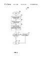
- FIG. 6is a flow diagram representing a brightness function for an auto-calibration procedure according to an embodiment of the present invention.
- FIG. 7Ais a diagram illustrating an exemplary bright gray level recorded by an image sensor for each pixel in a bright test strip.
- FIG. 7Bis a diagram illustrating an exemplary dark gray level recorded by an image sensor for each pixel in a dark measured test strip.
- FIG. 7Cis a graphical representation of gray level intensity versus reflectivity for corresponding bright and dark pixels.
- FIG. 8Ais a flow diagram representing a focus check function for an auto-calibration procedure according to an embodiment of the present invention.
- FIG. 8Bis a diagram illustrating an exaggerated example of an edge of a Ronchi ruling scanned using a fingerprint scanner versus an edge of a Ronchi ruling from a focus check strip of a calibration target prior to being scanned.
- FIG. 8Cis a diagram illustrating an ideal histogram for a Ronchi ruling.
- FIG. 8Dis a diagram illustrating a histogram for a scanned image of a Ronchi ruling.
- FIG. 9is a flow diagram representing a geometric distortion function for an auto-calibration procedure according to an embodiment of the present invention.
- FIG. 10is a diagram illustrating the generation of a correction curve.
- FIG. 11is a flow diagram of a non-linear remapping of input pixels using a geometric correction curve.
- FIG. 12is a diagram illustrating a linear interpolation versus a reverse piecewise linear interpolation.
- FIG. 13is a flow diagram representing a method for a gray level linearity calibration and correction procedure.
- FIG. 14is an exemplary gray level test pattern.
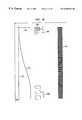
- FIG. 15is an exemplary curve of a digitized gray level test pattern.
- FIG. 16is a flow diagram representing a linearization process of a gray level linearity calibration and correction procedure.
- FIG. 17is a diagram illustrating an exemplary computer system.
- fingerrefers to any digit on a hand including, but not limited to, a thumb, an index finger, middle finger, ring finger, or a pinky finger.
- live scanrefers to a scan of any type of fingerprint image by a fingerprint scanner.
- a live scancan include, but is not limited to, a scan of a finger, a finger roll, a flat finger, slap print of four fingers, thumb print or palm print.
- fingerprint scanneris any type of scanner which can obtain an image of all or part of one or more fingers in a live scan including, but not limited to, a tenprint scanner.
- a “tenprint scanner”is a scanner that can capture images representative of ten fingers of a person. The captured images can be combined in any format including, but not limited to, an FBI tenprint format.
- platenrefers to a component that include an imaging surface upon which at least one finger is placed during a live scan.
- a platencan include, but is not limited to, an optical prism, set of prisms, or set of micro-prisms.
- FIG. 1is a high level block diagram illustrating an exemplary tenprint scanner according to an embodiment of the present invention.
- a tenprint scanner 100comprises a fingerprint scanner 102 , a personal computer 106 , and an interface cable 110 .
- Interface cable 110couples fingerprint scanner 102 to personal computer 106 .
- Fingerprint scanner 102comprises, inter alia, a first 1394 interface card. Fingerprint scanner 102 captures an image of a fingerprint. The fingerprint image, along with corresponding position data, are combined into a packet. The packet is sent from fingerprint scanner 102 using first interface card 104 to PC 106 via interface cable 110 .
- Personal computer 106comprises, inter alia, a second 1394 interface card 108 .
- Second interface card 108receives the packet for PC 106 .
- PC 106decodes the packet and forms an image of the fingerprint to be displayed BY PC 106 .
- the present inventionis described in terms of the above exemplary tenprint scanner. Description in these terms is provided for convenience only. It is not intended that the present invention be limited to application in this exemplary tenprint scanner. In fact, after reading the following description, it will become apparent to a person skilled in the relevant art(s) how to implement the calibration and correction procedure of the present invention in other biometric systems in which a biometric image of a measurable characteristic of a human being is captured.
- the calibration and correction procedure of the present inventionuses calibration targets that are scanned into fingerprint scanner 102 to perform calibration and correction of optimal settings in the tenprint scanner.
- the target informationis copied over to PC 106 via interface cable 106 .
- the actual calibration and correctionis performed on the computer side of tenprint scanner 100 .
- fingerprint scanner 102can carry out all or part of the calibration and correction procedure.
- Each calibration targetwill be described in detail with reference to FIGS. 4 and 14.
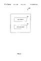
- FIG. 2is a high level block diagram illustrating a calibration and correction procedure according to an embodiment of the present invention.
- a calibration and correction procedure 200is comprised of an auto-calibration procedure 202 and a gray level linearity calibration and correction procedure 204 .
- Auto-calibration procedure 202is performed on a daily basis.
- Gray level linearity procedure 204is performed at the factory or by a field technician.
- Gray level linearity procedure 204may also be performed by an operator of tenprint scanner 100 . Both auto-calibration procedure 202 and gray level linearity procedure 204 will be described below with reference to FIGS. 3-12 and 13 - 16 , respectively.
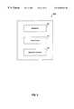
- FIG. 3is a high level block diagram illustrating auto-calibration procedure 202 according to an embodiment of the present invention.
- Auto-calibration procedure 202is comprised of three functions: a brightness function 302 , a focus check function 304 , and a geometric distortion function 306 .
- functions 302 - 306are performed as one routine.
- functions 302 - 306are performed as separate routines.
- Brightness function 302corrects for distortions in brightness due to pixel to pixel variations in the gain and offset of an image sensor. Brightness function 302 will be described in detail with reference to FIGS. 6, and 7 A- 7 C.
- Focus check function 304identifies when tenprint scanner 100 is out of focus. Focus check function 304 will be described in detail with reference to FIGS. 8A-8C.
- Geometric distortion function 306corrects for imperfect linearity in the geometry. Geometric distortion function 306 will be described below with reference to FIGS. 9-12.
- FIG. 4is a diagram (not drawn to scale) illustrating an exemplary calibration target 400 for auto-calibration procedure 202 .
- Calibration target 400is comprised of four sections: a geometry strip 402 , a focus strip 404 , a bright or white strip 406 , and a dark or black strip 408 .
- Geometry strip 402is used with geometric distortion function 306 .
- Focus strip 404is used with focus check function 304 .
- Bright strip 406 and dark strip 408are used with brightness function 302 .
- Geometry strip 402is comprised of a Ronchi ruling of alternating white and black bars.
- the Ronchi ruling of geometry strip 402has a fifty percent (50%) duty cycle.
- the width of the black barsare equivalent to the width of the white bars.
- the spacingis one cycle per millimeter. Therefore, the period is one millimeter.
- Focus strip 404is comprised of three Ronchi rulings of alternating white and black bars, each Ronchi ruling is separated by white space.
- the three Ronchi rulings of focus strip 404have a fifty percent (50%) duty cycle.
- the spacingis 15 cycles per millimeter.
- the three Ronchi rulings in focus target section 404correspond to three different points of potential scan area or image area of a prism in tenprint scanner 100 .
- FIG. 5is a diagram (not drawn to scale) illustrating the three different points of a potential scan area or image area of fingerprint scanner 102 . Shown in FIG. 5 are a prism 502 , a camera 504 , a plurality of lenses 506 and a finger 508 . Finger 508 is placed directly on the flat surface of prism 502 . Camera 504 is looking toward finger 508 through a plurality of lenses 506 and a mirror (not shown). The longest distance in which camera 504 must focus is indicated as focus point 510 . The shortest distance in which camera 504 must focus is indicated as focus point 514 . A distance midway between focus point 514 and focus point 510 in which camera 504 must focus is indicated as focus point 512 .
- the angle at which camera 504 is titledcompensates for the varying distances of focus points 510 , 512 , and 514 .
- the focus of finger 508must be as good at focus point 514 as it is at focus points 510 and 512 .
- the three Ronchi rulings of focus strip 404correspond to the three focus points 510 , 512 , and 514 of FIG. 5 .
- Bright strip 406is a white or a bright gray strip.
- the color of strip 406is consistent throughout having a known brightness, density, and reflectivity.
- Dark strip 408is a black or dark gray strip.
- the color of strip 408is consistent throughout having a known brightness, density, and reflectivity.
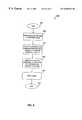
- FIG. 6is a flow diagram representing brightness function 302 for auto-calibration procedure 202 . The process begins with step 602 where control immediately passes to step 604 .
- step 604bright and dark strips 406 and 408 of auto-calibration target 400 are scanned multiple times using fingerprint scanner 102 .
- the scanned stripsare averaged to eliminate any noise, resulting in one scanned bright strip and one scanned dark strip.
- the reflectivity of bright strip 406is ninety percent (90%).
- the reflectivity of dark strip 408is ten percent (10%).
- the present inventionis described using reflectivity measurements of 90% and 10% for bright and dark strips 406 and 408 , the present invention is not limited to these reflectivity values.
- One skilled in the relevant art(s)would know that other reflectivity values for both bright and dark strips 406 and 408 may be used without departing from the scope of the present invention.
- FIG. 7Ais a diagram illustrating a graphical representation of an exemplary bright gray level 702 recorded by the image sensor for each pixel on the scanned bright strip.
- FIG. 7Bis a diagram illustrating a graphical representation of an exemplary dark gray level 704 recorded by the image sensor for each pixel on the scanned dark strip.
- both graphsshould resemble a straight line since the gray levels throughout bright strip 406 and dark strip 408 do not vary.
- the gray level recording for bright strip 406might read 200
- the gray level recording for dark strip 408might read 20 .
- gray level recordings for both bright gray level 702 and dark gray level 704vary in brightness and darkness, respectively, over pixels 0 to 2700 .
- Bright gray level 702is shown in FIG. 7A to fluctuate around a value of 200.
- Dark gray level 704is shown in FIG. 7B to fluctuate around a value of 20. This is due to fabrication variations in the silicon of the CMOS image sensor.
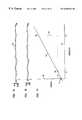
- FIG. 7Cis a diagram illustrating a graphical representation of gray level intensity 716 versus reflectivity 718 for corresponding pixels of bright and dark gray levels 702 and 704 (shown in FIGS. 7 A and 7 B). For each pixel, the bright and dark gray level is plotted versus reflectivity. As previously stated, the reflectivity of bright strip 406 is 90% and the reflectivity of dark strip 408 is 10%.
- pixel 14might have a gray level recording of 200 for bright gray level 702 and a gray level recording of 17 for dark gray level 704 .
- a bright gray level 708 for pixel 14is plotted at 90% reflectivity while a dark gray level 706 for pixel 14 is plotted at 10% reflectivity.
- a straight line 710is drawn through bright gray level 708 and dark gray level 706 for pixel 14 .
- the equation of straight line 710is determined by a y-intercept value, b 712 and a slope of line 710 , m 714 , where m 714 is equal to the rise over the run.
- the equation of a straight line, the y-intercept, the slope, and the rise over the runare well known mathematical concepts.
- correction coefficients for each pixelare determined that would cause all of the pixels of bright gray level 702 and dark gray level 704 to respond uniformly.
- Correction coefficients for each pixelinclude an offset and a gain.
- the offsetmust be subtracted from the pixel gray level value so that all equations of the line pass through the origin.
- the gainis multiplied by the pixel gray level value to cause all slopes to be equal. This is accomplished by determining y-intercept value or b 712 and slope m 714 of straight line 710 for each pixel. One over m 714 (1/m) is the gain value and y-intercept, b 712 is the offset value.
- the corrected pixel valueis
- P corris the corrected pixel value
- P measuredis the measured pixel value
- bis the offset value
- 1/mis the gain
- a small amount of tweakingmay occur to accurately adjust the corrected pixel value.
- the corrected pixel valueis
- ⁇is a multiplier used to adjust the overall brightness up or down.
- Multiplying all pixels by ⁇may introduce holes or aliasing affects because no smoothing or interpolating techniques are employed. Rather than tweak the corrected pixel value using ⁇ , a preferred method would be to adjust the gain and/or exposure time on the analog side of tenprint scanner 100 (that is, prior to digitizing the data for transmission to personal computer 106 ). Control then passes to step 610 .
- step 610slope m 714 or gain value and y-intercept, b 712 or offset value are stored for each pixel value.
- the gain and offset valuesare utilized for normalizing the brightness of each fingerprint scanned into tenprint scanner 100 . Control then passes to step 612 where the process ends.
- FIG. 8Ais a flow diagram illustrating focus check function 304 for auto-calibration procedure 202 .
- Focus check function 304does not correct for focus. Instead, focus check function 304 checks to see if tenprint scanner 100 has gone out of focus. The process begins with step 802 where control immediately passes to step 804 .
- step 804focus test strip 404 is scanned using fingerprint scanner 102 multiple times and averaged to eliminate any noise. The average of multiple scans of focus test strip 404 results in a measured focus test strip. Control then passes to step 806 .
- a histogramis generated using the measured focus test strip.
- Each pixelis quantized into 8 bits, with 256 discrete values in which to fall.
- the dimension of a pixelis 7 micrometers.
- the histogramis comprised of intensity or brightness values versus gray level values. Bins in the histogram correspond to each possible gray level value.
- the intensity or brightness level of each pixel in the measured focus test stripis accounted for in the proper gray level value bin by maintaining a tally for each gray level value bin. That is, the pixels of the measured focus test strip that fall within a specific gray level value are counted and the total count is placed in the corresponding gray level value bin.
- focus check strip 404is comprised of three Ronchi rulings, each Ronchi ruling comprised of alternating light and dark bars having a fifty percent (50%) duty cycle. Each Ronchi ruling is separated by white space. Histograms are generated for each of the three Ronchi rulings for determining the focus at the three focus points 510 , 512 , and 514 . That is, focus point 514 located at the tip of finger 508 , focus point 512 located midway between focus point 514 and 510 , and focus point 510 located at the farthest end of finger 508 (as shown in FIG. 5 ).
- FIG. 8Bis a diagram illustrating an exaggerated example of a scanned edge of a Ronchi ruling using fingerprint scanner 102 versus an edge of a Ronchi ruling from focus strip 404 .
- FIG. 8Bshows a sharp edge 820 of a Ronchi ruling from focus check strip 404 and a rounded edge 822 of a scanned Ronchi ruling using fingerprint scanner 102 .
- the dark barshave a gray level intensity of 0 and the bright bars have a gray level intensity of 250.
- Sharp edge 820illustrates an instantaneous transition from an intensity of zero to an intensity of 250, for example.
- a histogram representation of the Ronchi rulingshould have a lot of values around zero (0) representative of the dark bars and a lot of values around 250 or the grayscale value of the light bars.
- FIG. 8Cis a diagram illustrating an ideal histogram 830 for a Ronchi ruling.
- FIG. 8Cshows an accumulation of values at zero ( 832 ) representative of the dark bars in the Ronchi ruling and an accumulation of values at 250 ( 834 ) representative of the light bars in the Ronchi ruling.
- An ideal image sensor that captures a Ronchi ruling imagewould record pixels with an intensity of all zeroes for the dark pixels and an intensity representative of the light bars for the light pixels. In reality, the image sensor captures Ronchi ruling 822 having a rounded effect at the edges, as shown in FIG. 8 B.
- FIG. 8Dis a diagram illustrating a histogram 840 for a scanned image of a Ronchi ruling.
- FIG. 8Dshows a histogram having values hovering around zero (representative of the dark bars) and having values hovering around 250 (representative of the light bars).
- step 808the quality factor, Q, of the bright peak in the histogram is determined.
- the quality factor, Qis the ratio of the height of the bright peak to its width at half amplitude. Note that the bright peak is the peak hovering around 250 in FIG. 8 D.
- the quality factor, Qis directly related to the sharpness of focus. The taller and narrower the hump, the better the focus. Control then passes to step 810 .
- step 810the measured Q is compared to a preset threshold value. Control then passes to decision step 812 .
- decision step 812it is determined whether the quality factor, Q, is less than the preset threshold value. If it is determined that the quality factor, Q, is less than the preset threshold value, control passes to step 814 .
- step 814an error message is generated indicating that tenprint scanner 100 needs refocusing. This could mean cleaning or aligning lenses 506 in fingerprint scanner 102 .
- a maintenance callcan be placed to have a field engineer correct the focus.
- Controlthen passes to step 816 .
- a servo-control systemcan be added to automatically adjust the position of lenses 506 to maximize the quality factor, Q, value.
- step 816the process ends. Note that the above process is performed for each of the three Ronchi rulings in focus strip 404 .
- FIG. 9is a flow diagram representing geometric distortion function 306 for auto-calibration procedure 202 .
- Geometric distortion function 306corrects for an imperfect linear geometry. The process begins in step 902 where control immediately passes to step 904 .
- step 904geometry strip 402 of auto-calibration target 400 , comprised of a plurality of Ronchi rulings, is scanned multiple times using fingerprint scanner 102 .
- the scanned geometry strips 402are averaged to eliminate any noise.
- the average of multiple scans of geometry strip 402results in a measured geometry test strip. Control then passes to step 906 .
- FIG. 10is a diagram illustrating the generation of a correction curve. Shown in FIG. 10 are geometry strip 1002 , a scanned and averaged image of geometry strip 402 or measured geometry test strip 1004 , and an exemplary geometric correction curve 1012 . As previously stated, the Ronchi rulings of geometry strip 402 are precisely one millimeter apart. As can be seen from FIG. 10, measured geometry test strip 1004 results in lines that are fairly close together on one end, and as the pattern progresses, the lines become fatter and farther apart on the other end. Physically, each bar is the same distance apart (as shown in geometry strip 402 ), but measured geometry test strip 1004 might be 1.7 pixels apart ( 1006 ) at one end and 4.2 pixels apart ( 1008 ) at the other end.
- Geometric correction curve 1012To generate geometric correction curve 1012 , the exact centers of each bar is determined using a sub-pixel resolution algorithm.
- the sub-pixel resolution algorithmis well known to those skilled in the relevant art(s).
- the sub-pixel resolution algorithmresults in precise floating point number center points for each pixel.
- Geometric correction curve 1012includes a y-axis of center points 1010 and an x-axis of pixels 1011 .
- Geometric correction curve 1012is therefore a plot of the exact center points for each pixel versus pixel number.
- step 906once correction curve 1012 has been generated, control then passes to step 908 .
- step 908non-linear remapping of input pixels using geometric correction curve 1012 is performed.
- the non-linear remapping of input pixels using geometric correction curve 1012is described in detail with reference to FIG. 11 .
- Controlthen passes to decision step 910 .
- decision step 910it is determined whether the data is out of bounds for correction. If the data is out of bounds for correction, control passes to step 912 .
- step 912an error message is generated indicating that the data is out of bounds for correction. Control then passes to step 914 .
- controlpasses to step 914 .
- step 914the process ends.
- FIG. 11A flow diagram of the non-linear remapping of input pixels using geometric correction curve 1012 is shown in FIG. 11 .
- the processbegins with step 1102 where control immediately passes to step 1104 .
- step 1104a coefficient is determined for each input pixel from geometric correction curve 1012 .
- the coefficientis extracted from geometric correction curve 1012 . That is, for each pixel value, a corresponding floating point number is taken from curve 1012 as the coefficient for that pixel value. Control then passes to step 1106 .
- FIG. 12is a diagram illustrating a simple linear interpolation versus a reverse piecewise linear interpolation.
- simple linear interpolationvalues are to be determined that lie between given sample values. With reverse piecewise linear interpolation, the opposite occurs. A sample value is given and values surrounding that sample value must be determined.
- step 1106the reverse piecewise linear interpolation method uses the floating point coefficient extracted from geometric correction curve 1012 as the known sample value and splits off part of the floating point coefficient to obtain the surrounding two points.
- the first surrounding pointis the nearest whole number below the floating point coefficient.
- the second surrounding pointis the nearest whole number above the floating point coefficient.
- a pixel number 17has a corresponding floating point coefficient of 20.1 from geometric correction curve 1012 .
- This coefficientremaps pixel 17 into pixel 20 and pixel 21 .
- the grayscale values for pixels 20 and 21are weighted using the grayscale value recorded for input pixel 17 . Weighted amounts are based on the reflectivity of the light bars and the dark bars.
- the reflectivity of the light barsmight be ninety percent (90%) and the reflectivity of the dark bars might be ten percent (10%).
- 90% of the grayscale value of pixel 17will go into pixel 20 because the absolute value of (20.1-20) is smaller than the absolute value of (20.1-21), and ten percent (10%) of the grayscale value of pixel 17 will go into pixel 21 because the absolute value of (20.1-21) is greater than the absolute value of (20.1-20). That is, pixel 20 is closer to coefficient 20.1 than pixel 21 . Therefore, pixel 20 should have a larger grayscale value than pixel 21 .
- This method of remapping using the piecewise linear interpolation methodis repeated for each pixel. Grayscale values for each remapped pixel are then summed or accumulated. Control then passes to step 1108 .
- step 1108the grayscale values for each remapped pixel are stored in memory. These values are used to correct for geometric distortions when taking fingerprints. Control then passes to step 1110 where the process ends.
- FIG. 13is a flow diagram representing a method for gray level linearity calibration and correction procedure 204 .
- gray level linearity calibration and correction procedure 204is performed at the factory or by a field engineer.
- gray level linearity calibration and correction procedure 204may be performed by an operator periodically in a similar manner as auto-calibration procedure 202 .
- Gray level linearity calibration and correction procedure 204uses a gray level test pattern as its calibration target. The process begins with step 1302 where control immediately passes to step 1304 .
- a gray level test patternis scanned multiple times into tenprint scanner 100 using fingerprint scanner 102 .
- the multiple scans of the gray level test patternare averaged to eliminate any noise.
- the averaged gray level test patternis digitized to generate a digitized or measured gray level test pattern.
- FIG. 14is an exemplary gray level test pattern.
- a gray level test pattern 1400is comprised of fourteen gray level patches 402 , each patch 402 of a known gray level value. Gray level patches 402 vary from dark gray to light gray.
- controlpasses to step 1306 .
- a curve of the digitized gray level test patternis generated.
- An exemplary curve of the digitized gray level test patternis shown in FIG. 15.
- a graph 1500is comprised of a y-axis 1502 of gray level intensity, an x-axis 1504 comprised of fourteen gray level values corresponding to gray level patches 1402 , from the darkest gray level patch to the lightest or brightest gray level patch, and a plotted curve 1506 of an exemplary digitized or measured gray level test pattern.
- Plotted curve 1506resembles an s-shaped curve.
- An actual curve 1508 of the true or actual gray level test pattern valuesis shown in phantom. Actual curve 1508 is a straight line.
- step 1308measured gray level test pattern curve 1506 is linearized. Linearization step 1308 is described in detail below with reference to FIG. 16 . The linearized response is applied to the scanned fingerprint data when fingerprints are taken. Control then passes to step 1310 where the process ends.
- FIG. 16is a flow diagram representing the linearization process 1308 of gray level linearity calibration and correction procedure 204 . The process begins with step 1602 where control is immediately passed to step 1604 .
- step 1604measured gray level values are compared with actual gray level values using a look-up table. Control then passes to step 1606 .
- step 1606it is determined whether measured gray level values are equal to actual gray level values. If it is determined that the measured gray level values are not equal to the actual gray level values, control passes to step 1608 .
- step 1608a difference vector, or linearized response, equal to the difference between the measured values and the actual values is determined. Control then passes to step 1612 .
- step 1610the difference vector is set to zero. Control then passes to step 1612 .
- step 1612the difference vector is stored in memory in order to linearize the gray level brightness and contrast during fingerprinting. Control then passes to step 1614 where the process ends.
- the present inventionmay be implemented using hardware, software, or a combination thereof and may be implemented in one or more computer systems or other processing systems. In fact, in one embodiment, the invention is directed toward one or more computer systems capable of carrying out the functionality described herein.
- An example of a computer system 1700is shown in FIG. 17 .
- the computer system 1700includes one or more processors, such as processor 1703 .
- the processor 1703is connected to a communication bus 1702 .
- Various software embodimentsare described in terms of this exemplary computer system. After reading this description, it will be apparent to a person skilled in the relevant art how to implement the invention using other computer systems and/or computer architectures.
- Computer system 1700also includes a main memory 1705 , preferably random access memory (RAM), and may also include a secondary memory 1710 .
- the secondary memory 1710may include, for example, a hard disk drive 1712 and/or a removable storage drive 1714 , representing a floppy disk drive, a magnetic tape drive, an optical disk drive, etc.
- the removable storage drive 1714reads from and/or writes to a removable storage unit 1718 in a well-known manner.
- Removable storage unit 1718represents a floppy disk, magnetic tape, optical disk, etc., which is read by and written to by removable storage drive 1714 .
- the removable storage unit 1718includes a computer usable storage medium having stored therein computer software and/or data.
- secondary memory 1710may include other similar means for allowing computer programs or other instructions to be loaded into computer system 1700 .
- Such meansmay include, for example, a removable storage unit 1722 and an interface 1720 . Examples of such may include a program cartridge and cartridge interface (such as that found in video game devices), a removable memory chip (such as an EPROM, or PROM) and associated socket, and other removable storage units 1722 and interfaces 1720 which allow software and data to be transferred from the removable storage unit 1722 to computer system 1700 .
- Computer system 1700may also include a communications interface 1724 .
- Communications interface 1724allows software and data to be transferred between computer system 1700 and external devices. Examples of communications interface 1724 may include a modem, a network interface (such as an Ethernet card), a communications port, a PCMCIA slot and card, etc.
- Software and data transferred via communications interface 1724are in the form of signals 1728 which may be electronic, electromagnetic, optical, or other signals capable of being received by communications interface 1724 . These signals 1728 are provided to communications interface 1724 via a communications path (i.e., channel) 1726 .
- This channel 1726carries signals 1728 and may be implemented using wire or cable, fiber optics, a phone line, a cellular phone link, an RF link, and other communications channels.
- computer program productrefers to removable storage units 1718 , 1722 , and signals 1728 . These computer program products are means for providing software to computer system 1700 . The invention is directed to such computer program products.
- Computer programsare stored in main memory 1705 , and/or secondary memory 1710 and/or in computer program products. Computer programs may also be received via communications interface 1724 . Such computer programs, when executed, enable the computer system 1700 to perform the features of the present invention as discussed herein. In particular, the computer programs, when executed, enable the processor 1703 to perform the features of the present invention. Accordingly, such computer programs represent controllers of the computer system 1700 .
- the softwaremay be stored in a computer program product and loaded into computer system 1700 using removable storage drive 1714 , hard drive 1712 or communications interface 1724 .
- the control logicwhen executed by the processor 1703 , causes the processor 1703 to perform the functions of the invention as described herein.
- the inventionis implemented primarily in hardware using, for example, hardware components such as application specific integrated circuits (ASICs).
- ASICsapplication specific integrated circuits
- the inventionis implemented using a combination of both hardware and software.
- the present inventionis not limited to the embodiment of fingerprint scanner 102 .
- the present inventioncan be used with any biometric imaging system that scans a measurable characteristic of a human being for identity purposes.
- the previous description of the preferred embodimentsis provided to enable any person skilled in the art to make or use the present invention. While the invention has been particularly shown and described with reference to preferred embodiments thereof, it will be understood by those skilled in the relevant art(s) that various changes in form and detail may be made therein without departing from the spirit and scope of the invention.
Landscapes
- Engineering & Computer Science (AREA)
- Multimedia (AREA)
- Computer Networks & Wireless Communication (AREA)
- Signal Processing (AREA)
- Human Computer Interaction (AREA)
- Physics & Mathematics (AREA)
- General Physics & Mathematics (AREA)
- Theoretical Computer Science (AREA)
- Computer Hardware Design (AREA)
- General Engineering & Computer Science (AREA)
- Image Input (AREA)
Abstract
Description
Claims (20)
Priority Applications (6)
| Application Number | Priority Date | Filing Date | Title |
|---|---|---|---|
| US09/425,947US6658164B1 (en) | 1999-08-09 | 1999-10-25 | Calibration and correction in a fingerprint scanner |
| EP99966173AEP1208524A1 (en) | 1999-08-09 | 1999-12-15 | Calibration and correction in a fingerprint scanner |
| AU21782/00AAU2178200A (en) | 1999-08-09 | 1999-12-15 | Calibration and correction in a fingerprint scanner |
| PCT/US1999/029535WO2001011545A1 (en) | 1999-08-09 | 1999-12-15 | Calibration and correction in a fingerprint scanner |
| JP2001516124AJP2003506794A (en) | 1999-08-09 | 1999-12-15 | Calibration and correction in fingerprint scanners |
| US10/690,641US7010148B2 (en) | 1999-08-09 | 2003-10-23 | Calibration and correction in a fingerprint scanner |
Applications Claiming Priority (2)
| Application Number | Priority Date | Filing Date | Title |
|---|---|---|---|
| US14749899P | 1999-08-09 | 1999-08-09 | |
| US09/425,947US6658164B1 (en) | 1999-08-09 | 1999-10-25 | Calibration and correction in a fingerprint scanner |
Related Child Applications (1)
| Application Number | Title | Priority Date | Filing Date |
|---|---|---|---|
| US10/690,641ContinuationUS7010148B2 (en) | 1999-08-09 | 2003-10-23 | Calibration and correction in a fingerprint scanner |
Publications (1)
| Publication Number | Publication Date |
|---|---|
| US6658164B1true US6658164B1 (en) | 2003-12-02 |
Family
ID=26844991
Family Applications (2)
| Application Number | Title | Priority Date | Filing Date |
|---|---|---|---|
| US09/425,947Expired - LifetimeUS6658164B1 (en) | 1999-08-09 | 1999-10-25 | Calibration and correction in a fingerprint scanner |
| US10/690,641Expired - LifetimeUS7010148B2 (en) | 1999-08-09 | 2003-10-23 | Calibration and correction in a fingerprint scanner |
Family Applications After (1)
| Application Number | Title | Priority Date | Filing Date |
|---|---|---|---|
| US10/690,641Expired - LifetimeUS7010148B2 (en) | 1999-08-09 | 2003-10-23 | Calibration and correction in a fingerprint scanner |
Country Status (5)
| Country | Link |
|---|---|
| US (2) | US6658164B1 (en) |
| EP (1) | EP1208524A1 (en) |
| JP (1) | JP2003506794A (en) |
| AU (1) | AU2178200A (en) |
| WO (1) | WO2001011545A1 (en) |
Cited By (24)
| Publication number | Priority date | Publication date | Assignee | Title |
|---|---|---|---|---|
| US20020021827A1 (en)* | 2000-08-18 | 2002-02-21 | Cross Match Technologies, Inc. | Fingerprint scanner auto-capture system and method |
| US20020021456A1 (en)* | 2000-07-11 | 2002-02-21 | Hideyuki Toriyama | Image reading method including shading correction and image reading device therefor |
| US20020090147A1 (en)* | 2000-12-18 | 2002-07-11 | Scott Walter G. | Palm scanner using a programmable nutating mirror for increased resolution |
| US20030011828A1 (en)* | 2001-07-13 | 2003-01-16 | Umax Data Systems Inc. | High-speed calibration method and system for an image-capture apparatus |
| US20040085594A1 (en)* | 2002-10-30 | 2004-05-06 | Shih-Zheng Kuo | Image compensating method |
| US6744910B1 (en)* | 1999-06-25 | 2004-06-01 | Cross Match Technologies, Inc. | Hand-held fingerprint scanner with on-board image normalization data storage |
| US20040165024A1 (en)* | 2003-02-21 | 2004-08-26 | Ferran Vilanova | Economical method & apparatus for objectively fixing error thresholds and checking color accuracy |
| US20040208349A1 (en)* | 2003-04-18 | 2004-10-21 | Casio Computer Co., Ltd. | Fingerprint image reading apparatus |
| WO2005076195A1 (en)* | 2004-02-04 | 2005-08-18 | Julian Mark Douglas Ashbourn | Automatic performance calibration (apc) |
| GB2412775A (en)* | 2004-03-31 | 2005-10-05 | Seiko Epson Corp | Fingerprint scanner and method of auto focusing one |
| US7095880B2 (en)* | 1999-08-19 | 2006-08-22 | Cross Match Technologies, Inc. | Method and apparatus for rolled fingerprint capture |
| US7190535B2 (en) | 2002-12-06 | 2007-03-13 | Cross Match Technologies, Inc. | Non-planar prism |
| US20080055663A1 (en)* | 2001-06-19 | 2008-03-06 | Chui-Kuei Chiu | Calibration method of an image-capture apparatus |
| US20090226052A1 (en)* | 2003-06-21 | 2009-09-10 | Vincent Fedele | Method and apparatus for processing biometric images |
| US20100027078A1 (en)* | 2008-08-04 | 2010-02-04 | Xerox Corporation | Multipass image scans for increased measurement resolution during calibration routines |
| US7728959B2 (en) | 2003-06-21 | 2010-06-01 | Aprilis, Inc. | Acquisition of high resolution biometric images |
| US20130070977A1 (en)* | 2011-09-21 | 2013-03-21 | Shahram Orandi | Standard calibration target for contactless fingerprint scanners |
| US20130287270A1 (en)* | 2012-04-25 | 2013-10-31 | Jack Harper | Artificial intelligence methods for difficult forensic fingerprint collection |
| US9607189B2 (en) | 2015-01-14 | 2017-03-28 | Tactilis Sdn Bhd | Smart card system comprising a card and a carrier |
| US10037528B2 (en) | 2015-01-14 | 2018-07-31 | Tactilis Sdn Bhd | Biometric device utilizing finger sequence for authentication |
| US20180253587A1 (en)* | 2017-03-02 | 2018-09-06 | Zwipe As | Fingerprint sensor system |
| US10395227B2 (en) | 2015-01-14 | 2019-08-27 | Tactilis Pte. Limited | System and method for reconciling electronic transaction records for enhanced security |
| US11443020B2 (en) | 2019-12-31 | 2022-09-13 | Wipro Limited | Method and system for alleviating authenticity of sensors in biometric authentication |
| US11502817B2 (en) | 2020-02-12 | 2022-11-15 | Wipro Limited | Enhanced data security system and method thereof |
Families Citing this family (17)
| Publication number | Priority date | Publication date | Assignee | Title |
|---|---|---|---|---|
| FR2826151B1 (en)* | 2001-06-13 | 2004-12-17 | Sagem | COLOR FINGERPRINT RECOGNITION METHOD AND COMPUTER SYSTEM FOR CARRYING OUT SAID METHOD |
| US7267799B1 (en)* | 2002-08-14 | 2007-09-11 | Detekt Biomedical, L.L.C. | Universal optical imaging and processing system |
| US8068646B2 (en)* | 2005-09-06 | 2011-11-29 | Identification International, Inc. | System and method for implementing algorithmic correction of image distortion within a fingerprint imaging system |
| KR101092303B1 (en)* | 2009-05-26 | 2011-12-13 | 주식회사 유니온커뮤니티 | Fingerprint reader and method for acquiring fingerprint data |
| US8799167B2 (en) | 2010-07-13 | 2014-08-05 | Tec Solutions, Inc. | Biometric authentication system and biometric sensor configured for single user authentication |
| JP5315302B2 (en)* | 2010-07-27 | 2013-10-16 | 株式会社日立ハイテクノロジーズ | Scanning transmission electron microscope and axis adjusting method thereof |
| US8824792B2 (en)* | 2012-07-25 | 2014-09-02 | Ib Korea Ltd. | Image element brightness adjustment |
| SE1550411A1 (en)* | 2015-04-07 | 2016-10-08 | Fingerprint Cards Ab | Electronic device comprising fingerprint sensor |
| CN105528592A (en)* | 2016-01-18 | 2016-04-27 | 北京集创北方科技股份有限公司 | Fingerprint scanning method and device and gesture recognition method and device |
| CN106164933B (en)* | 2016-03-22 | 2019-06-07 | 深圳市汇顶科技股份有限公司 | Bearing calibration, device and the terminal of fingerprint image |
| KR102684881B1 (en) | 2017-01-06 | 2024-07-16 | 삼성전자주식회사 | Method for processing distortion of fingerprint image and apparatus thereof |
| WO2019014801A1 (en)* | 2017-07-17 | 2019-01-24 | 深圳市汇顶科技股份有限公司 | Method for determining optical sensing correction parameters, biometric detection apparatus and electronic terminal |
| US11301664B2 (en)* | 2018-09-12 | 2022-04-12 | Fingerprint Cards Anacatum Ip Ab | Reconstruction of fingerprint subimages |
| KR20210066093A (en)* | 2019-11-27 | 2021-06-07 | 삼성디스플레이 주식회사 | Calibration method of fingerprint sensor and display device using the same |
| TWI799071B (en) | 2021-03-03 | 2023-04-11 | 神盾股份有限公司 | Under-screen fingerprint sensing device and fingerprint sensing method |
| US11657643B1 (en)* | 2022-01-17 | 2023-05-23 | Novatek Microelectronics Corp. | Fingerprint sensing device |
| CN116503408B (en)* | 2023-06-28 | 2023-08-25 | 曲阜远大集团工程有限公司 | Scanning technology-based steel structure surface defect detection method |
Citations (73)
| Publication number | Priority date | Publication date | Assignee | Title |
|---|---|---|---|---|
| US3699519A (en)* | 1971-04-30 | 1972-10-17 | North American Rockwell | Fingerprint analysis device |
| US4032975A (en) | 1974-02-25 | 1977-06-28 | Mcdonnell Douglas Corporation | Detector array gain compensation |
| US4210899A (en) | 1975-06-23 | 1980-07-01 | Fingermatrix, Inc. | Fingerprint-based access control and identification apparatus |
| US4253086A (en) | 1978-07-28 | 1981-02-24 | Szymon Szwarcbier | Process and apparatus for positive identification of customers |
| US4601195A (en) | 1985-04-11 | 1986-07-22 | Rheometrics, Inc. | Apparatus and method for measuring viscoelastic properties of materials |
| US4669487A (en) | 1985-10-30 | 1987-06-02 | Edward Frieling | Identification device and method |
| US4783823A (en) | 1985-09-16 | 1988-11-08 | Omron Tateisi Electronics, Co. | Card identifying method and apparatus |
| US4784484A (en) | 1985-05-02 | 1988-11-15 | Jydsk Telefon A/S | Method and apparatus for automatic scanning of fingerprints |
| US4792226A (en) | 1987-02-27 | 1988-12-20 | C.F.A. Technologies, Inc. | Optical fingerprinting system |
| US4905293A (en) | 1984-07-18 | 1990-02-27 | Nec Corporation | Image input device |
| US4942482A (en) | 1985-08-09 | 1990-07-17 | Sony Corporation | Automatic page-turning device |
| US5185673A (en)* | 1991-06-12 | 1993-02-09 | Hewlett-Packard Company | Automated image calibration |
| US5253085A (en) | 1990-09-25 | 1993-10-12 | Hitachi, Ltd. | Variable scanning speed optical scanning device |
| US5291318A (en)* | 1992-11-02 | 1994-03-01 | Xerox Corporation | Holographic member for a real-time clock in a raster output scanner |
| US5363318A (en)* | 1992-03-23 | 1994-11-08 | Eastman Kodak Company | Method and apparatus for adaptive color characterization and calibration |
| EP0623890A2 (en) | 1993-05-07 | 1994-11-09 | Nippon Telegraph And Telephone Corporation | Method and apparatus for image processing |
| US5412463A (en) | 1992-06-06 | 1995-05-02 | Central Research Laboratories Limited | Finger guide with orthogonal guide surfaces |
| US5469506A (en) | 1994-06-27 | 1995-11-21 | Pitney Bowes Inc. | Apparatus for verifying an identification card and identifying a person by means of a biometric characteristic |
| US5483601A (en) | 1992-02-10 | 1996-01-09 | Keith Faulkner | Apparatus and method for biometric identification using silhouette and displacement images of a portion of a person's hand |
| US5509083A (en) | 1994-06-15 | 1996-04-16 | Nooral S. Abtahi | Method and apparatus for confirming the identity of an individual presenting an identification card |
| US5598474A (en) | 1994-03-29 | 1997-01-28 | Neldon P Johnson | Process for encrypting a fingerprint onto an I.D. card |
| US5625448A (en) | 1995-03-16 | 1997-04-29 | Printrak International, Inc. | Fingerprint imaging |
| US5649128A (en) | 1993-11-22 | 1997-07-15 | International Business Machines Corporation | Multiple bus interface adapter for connection to a plurality of computer bus architectures |
| US5650842A (en) | 1995-10-27 | 1997-07-22 | Identix Incorporated | Device and method for obtaining a plain image of multiple fingerprints |
| WO1997041528A1 (en) | 1996-04-30 | 1997-11-06 | Identix Incorporated | Method and device for reducing smear in a rolled fingerprint image |
| GB2313441A (en) | 1996-05-18 | 1997-11-26 | Motorola Israel Ltd | Power conserving scanning method |
| WO1998009246A1 (en) | 1996-08-27 | 1998-03-05 | Kaba Schliesssysteme Ag | Method and device for recognizing non-unrolled fingerprints |
| US5745684A (en) | 1995-11-06 | 1998-04-28 | Sun Microsystems, Inc. | Apparatus and method for providing a generic interface between a host system and an asynchronous transfer mode core functional block |
| US5748768A (en)* | 1992-10-30 | 1998-05-05 | Kabushiki Kaisha Toshiba | Method and apparatus for correcting distortion in an imaging system |
| US5757278A (en) | 1994-12-26 | 1998-05-26 | Kabushiki Kaisha Toshiba | Personal verification system |
| US5767989A (en)* | 1995-10-05 | 1998-06-16 | Fuji Photo Film Co., Ltd. | Image inputting apparatus |
| US5793218A (en) | 1995-12-15 | 1998-08-11 | Lear Astronics Corporation | Generic interface test adapter |
| US5805777A (en) | 1995-10-11 | 1998-09-08 | Eastman Kodak Company | Extended printer control interface |
| US5809172A (en)* | 1996-04-17 | 1998-09-15 | Canon Kabushiki Kaisha | Non-linear aggregation mapping compression of image data and method |
| US5815252A (en) | 1995-09-05 | 1998-09-29 | Canon Kabushiki Kaisha | Biometric identification process and system utilizing multiple parameters scans for reduction of false negatives |
| US5818956A (en) | 1995-10-23 | 1998-10-06 | Tuli; Raja Singh | Extended fingerprint reading apparatus |
| US5825005A (en) | 1993-07-06 | 1998-10-20 | Behnke; Alfons | Method of encoding identification cards and verifying such encoded identification cards, and apparatus for carrying out such a method |
| US5828773A (en) | 1996-01-26 | 1998-10-27 | Harris Corporation | Fingerprint sensing method with finger position indication |
| US5832244A (en) | 1996-02-20 | 1998-11-03 | Iomega Corporation | Multiple interface input/output port for a peripheral device |
| EP0889432A2 (en) | 1997-07-03 | 1999-01-07 | Fujitsu Limited | Roller fingerprint image capturing system |
| US5859710A (en) | 1996-03-20 | 1999-01-12 | Intel Corporation | Digital copying system using a high speed data bus without the use of data buffers |
| US5862247A (en) | 1993-04-02 | 1999-01-19 | Borus Spezialverfahren Und -Gerate Im Sondermaschinenbau Gmbh | Personal and property identification system |
| US5869822A (en) | 1996-10-04 | 1999-02-09 | Meadows, Ii; Dexter L. | Automated fingerprint identification system |
| WO1999026187A1 (en) | 1997-11-17 | 1999-05-27 | Veridicom, Inc. | Automatic adjustment processing for sensor devices |
| EP0924656A2 (en) | 1997-12-22 | 1999-06-23 | TRW Inc. | Personal identification FOB |
| US5920384A (en) | 1997-12-09 | 1999-07-06 | Dew Engineering And Development Limited | Optical imaging device |
| US5920640A (en) | 1997-05-16 | 1999-07-06 | Harris Corporation | Fingerprint sensor and token reader and associated methods |
| US5928347A (en) | 1997-11-18 | 1999-07-27 | Shuttle Technology Group Ltd. | Universal memory card interface apparatus |
| US5960100A (en) | 1997-07-23 | 1999-09-28 | Hargrove; Tom | Credit card reader with thumb print verification means |
| US5960125A (en)* | 1996-11-21 | 1999-09-28 | Cognex Corporation | Nonfeedback-based machine vision method for determining a calibration relationship between a camera and a moveable object |
| US5973731A (en) | 1994-03-03 | 1999-10-26 | Schwab; Barry H. | Secure identification system |
| US5987155A (en) | 1997-10-27 | 1999-11-16 | Dew Engineering And Development Limited | Biometric input device with peripheral port |
| US5991467A (en) | 1996-07-18 | 1999-11-23 | Alps Electric Co., Ltd. | Image reading apparatus containing light receiving transistors and switching transistors |
| US5995014A (en) | 1997-12-30 | 1999-11-30 | Accu-Time Systems, Inc. | Biometric interface device for upgrading existing access control units |
| US6018739A (en) | 1997-05-15 | 2000-01-25 | Raytheon Company | Biometric personnel identification system |
| US6023522A (en) | 1997-05-05 | 2000-02-08 | Draganoff; Georgi H. | Inexpensive adaptive fingerprint image acquisition framegrabber |
| US6041372A (en) | 1996-12-30 | 2000-03-21 | Intel Corporation | Method and apparatus for providing a processor module for a computer system |
| US6055071A (en)* | 1996-05-10 | 2000-04-25 | Ricoh Company, Ltd. | Image forming apparatus |
| US6064779A (en) | 1997-07-23 | 2000-05-16 | Xros, Inc. | Handheld document scanner |
| US6064753A (en) | 1997-06-10 | 2000-05-16 | International Business Machines Corporation | System and method for distortion control in live-scan inkless fingerprint images |
| US6072891A (en) | 1997-02-21 | 2000-06-06 | Dew Engineering And Development Limited | Method of gathering biometric information |
| US6075876A (en) | 1997-05-07 | 2000-06-13 | Draganoff; Georgi Hristoff | Sliding yardsticks fingerprint enrollment and verification system and method |
| US6078265A (en) | 1998-02-11 | 2000-06-20 | Nettel Technologies, Inc. | Fingerprint identification security system |
| US6088585A (en) | 1997-05-16 | 2000-07-11 | Authentec, Inc. | Portable telecommunication device including a fingerprint sensor and related methods |
| US6104809A (en) | 1993-12-29 | 2000-08-15 | Pitney Bowes Inc. | Apparatus for verifying an identification card |
| US6122394A (en) | 1996-05-01 | 2000-09-19 | Xros, Inc. | Compact, simple, 2D raster, image-building fingerprint scanner |
| US6137893A (en)* | 1996-10-07 | 2000-10-24 | Cognex Corporation | Machine vision calibration targets and methods of determining their location and orientation in an image |
| US6178255B1 (en) | 1998-04-28 | 2001-01-23 | Cross Match Technologies, Inc. | Individualized fingerprint scanner |
| US6195447B1 (en)* | 1998-01-16 | 2001-02-27 | Lucent Technologies Inc. | System and method for fingerprint data verification |
| US6272562B1 (en) | 1999-05-28 | 2001-08-07 | Cross Match Technologies, Inc. | Access control unit interface |
| US6281931B1 (en)* | 1997-11-04 | 2001-08-28 | Tien Ren Tsao | Method and apparatus for determining and correcting geometric distortions in electronic imaging systems |
| US6327047B1 (en)* | 1999-01-22 | 2001-12-04 | Electronics For Imaging, Inc. | Automatic scanner calibration |
| US6347163B2 (en) | 1994-10-26 | 2002-02-12 | Symbol Technologies, Inc. | System for reading two-dimensional images using ambient and/or projected light |
Family Cites Families (75)
| Publication number | Priority date | Publication date | Assignee | Title |
|---|---|---|---|---|
| US348445A (en)* | 1886-08-31 | Method of and apparatus for manufacturing brick and tile | ||
| US351144A (en)* | 1886-10-19 | Log-bunk for saw-mills | ||
| US2500017A (en)* | 1948-07-07 | 1950-03-07 | Eastman Kodak Co | Apochromatic telescope objectives and systems including same |
| US3200701A (en)* | 1962-01-29 | 1965-08-17 | Ling Temco Vought Inc | Method for optical comparison of skin friction-ridge patterns |
| US3482498A (en) | 1967-05-09 | 1969-12-09 | Trw Inc | Ridge pattern recording apparatus |
| US3527535A (en)* | 1968-11-15 | 1970-09-08 | Eg & G Inc | Fingerprint observation and recording apparatus |
| US3617120A (en) | 1969-06-02 | 1971-11-02 | Stephen Roka | Fingerprint comparison apparatus |
| US4063226A (en) | 1974-03-18 | 1977-12-13 | Harris Corporation | Optical information storage system |
| US3947128A (en)* | 1974-04-19 | 1976-03-30 | Zvi Weinberger | Pattern comparison |
| US3968476A (en)* | 1974-07-17 | 1976-07-06 | Sperry Rand Corporation | Spurious signal removal in optical processor fingerprint identification apparatus |
| DE3072034D1 (en) | 1979-12-24 | 1987-10-29 | Electro Optic Dev | Method and device for carrying out a comparison between certain patterns, especially finger prints |
| US4544267A (en)* | 1980-11-25 | 1985-10-01 | Fingermatrix, Inc. | Finger identification |
| GB2089545A (en) | 1980-12-11 | 1982-06-23 | Watson Graham Michael | Optical Image Formation |
| EP0101772A1 (en) | 1982-09-01 | 1984-03-07 | Jerome Hal Lemelson | Computer security systems |
| JPS59103474A (en)* | 1982-12-04 | 1984-06-14 | Koyo Denshi Kogyo Kk | Device for discriminating focusing of image pickup device |
| JPS59153514U (en)* | 1983-03-31 | 1984-10-15 | 株式会社東海理化電機製作所 | Contact pattern observation device |
| US4537484A (en)* | 1984-01-30 | 1985-08-27 | Identix Incorporated | Fingerprint imaging apparatus |
| GB8525161D0 (en) | 1985-10-11 | 1985-11-13 | Blackwell V C | Personalised identification device |
| US4876726A (en)* | 1986-01-07 | 1989-10-24 | De La Rue Printrak, Inc. | Method and apparatus for contextual data enhancement |
| US5187747A (en)* | 1986-01-07 | 1993-02-16 | Capello Richard D | Method and apparatus for contextual data enhancement |
| DE3679819D1 (en)* | 1986-05-06 | 1991-07-18 | Siemens Ag | ARRANGEMENT AND METHOD FOR DETERMINING THE AUTHORIZATION OF PERSONS BY CHECKING YOUR FINGERPRINTS. |
| US5067162A (en) | 1986-06-30 | 1991-11-19 | Identix Incorporated | Method and apparatus for verifying identity using image correlation |
| US4811414A (en)* | 1987-02-27 | 1989-03-07 | C.F.A. Technologies, Inc. | Methods for digitally noise averaging and illumination equalizing fingerprint images |
| EP0308162A3 (en) | 1987-09-15 | 1990-06-06 | Identix Incorporated | Optical system for fingerprint imaging |
| US4933976A (en)* | 1988-01-25 | 1990-06-12 | C.F.A. Technologies, Inc. | System for generating rolled fingerprint images |
| FI893028A7 (en)* | 1988-06-23 | 1989-12-24 | Fujitsu Ltd | Device for detecting data from an uneven surface |
| US4946276A (en) | 1988-09-23 | 1990-08-07 | Fingermatrix, Inc. | Full roll fingerprint apparatus |
| US5067749A (en) | 1989-01-09 | 1991-11-26 | Land Larry D | Method and apparatus for obtaining and recording fingerprint indicia |
| CA1326304C (en) | 1989-01-17 | 1994-01-18 | Marcel Graves | Secure data interchange system |
| CA1286032C (en)* | 1989-09-28 | 1991-07-09 | James H. Lougheed | Optical scanning and recording apparatus for fingerprints |
| US5146102A (en)* | 1990-02-22 | 1992-09-08 | Kabushiki Kaisha Toshiba | Fingerprint image input apparatus including a cylindrical lens |
| US5054090A (en)* | 1990-07-20 | 1991-10-01 | Knight Arnold W | Fingerprint correlation system with parallel FIFO processor |
| US5230025A (en)* | 1990-08-31 | 1993-07-20 | Digital Biometrics, Inc. | Method and apparatus for capturing skin print images |
| US5131038A (en)* | 1990-11-07 | 1992-07-14 | Motorola, Inc. | Portable authentification system |
| US5249370A (en)* | 1990-11-15 | 1993-10-05 | Digital Biometrics, Inc. | Method and apparatus for fingerprint image processing |
| GB9027718D0 (en) | 1990-12-20 | 1991-02-13 | Emi Plc Thorn | Fingerprint imaging |
| US5222152A (en)* | 1991-11-19 | 1993-06-22 | Digital Biometrics, Inc. | Portable fingerprint scanning apparatus for identification verification |
| US5467403A (en) | 1991-11-19 | 1995-11-14 | Digital Biometrics, Inc. | Portable fingerprint scanning apparatus for identification verification |
| USD348445S (en) | 1992-01-31 | 1994-07-05 | Digital Biometrics, Inc. | Hand held fingerprint scanner for imaging and capturing a photographic image |
| US5416573A (en)* | 1993-09-10 | 1995-05-16 | Indentix Incorporated | Apparatus for producing fingerprint images which are substantially free of artifacts attributable to moisture on the finger being imaged |
| DE4332411A1 (en)* | 1993-09-23 | 1995-03-30 | Bayerische Motoren Werke Ag | Theft protection for motor vehicles with several control units for vehicle components |
| USD351144S (en) | 1993-12-07 | 1994-10-04 | Digital Biometrics, Inc. | Handheld finger print scanner for imaging and capturing a photographic image |
| US5384621A (en)* | 1994-01-04 | 1995-01-24 | Xerox Corporation | Document detection apparatus |
| EP0749610B1 (en) | 1994-02-18 | 2000-08-02 | Imedge Technology, Inc. | Compact device for producing an image of the surface of the topolographical surface structure of an object and a method of making the device |
| US5528355A (en)* | 1994-03-11 | 1996-06-18 | Idnetix Incorporated | Electro-optic palm scanner system employing a non-planar platen |
| DE4416507C5 (en)* | 1994-05-10 | 2006-10-19 | Volkswagen Ag | Method for detecting a use authorization for a vehicle |
| US5473144A (en) | 1994-05-27 | 1995-12-05 | Mathurin, Jr.; Trevor R. | Credit card with digitized finger print and reading apparatus |
| US5517528A (en)* | 1994-08-02 | 1996-05-14 | International Automated Systems, Inc. | Modulation method and apparatus for digital communications |
| US5689529A (en) | 1994-08-02 | 1997-11-18 | International Automated Systems, Inc. | Communications method and apparatus for digital information |
| US5640422A (en)* | 1994-08-02 | 1997-06-17 | International Automated Systems, Inc. | Digital communications modulation method and apparatus |
| US5613014A (en)* | 1994-10-12 | 1997-03-18 | Martin Marietta Corp. | Fingerprint matching system |
| US5596454A (en)* | 1994-10-28 | 1997-01-21 | The National Registry, Inc. | Uneven surface image transfer apparatus |
| US5615277A (en)* | 1994-11-28 | 1997-03-25 | Hoffman; Ned | Tokenless security system for authorizing access to a secured computer system |
| EP0795248A2 (en) | 1994-11-30 | 1997-09-17 | Digital Biometrics, Inc. | Palm printer |
| US5591949A (en)* | 1995-01-06 | 1997-01-07 | Bernstein; Robert J. | Automatic portable account controller for remotely arranging for payment of debt to a vendor |
| US5548394A (en)* | 1995-03-16 | 1996-08-20 | Printrak International Inc. | Scanning fingerprint reading |
| US5822445A (en)* | 1995-06-27 | 1998-10-13 | Dew Engineering And Development Limited | Apparatus for identifying fingerprints |
| CA2156236C (en)* | 1995-08-16 | 1999-07-20 | Stephen J. Borza | Biometrically secured control system for preventing the unauthorized use of a vehicle |
| ATE278227T1 (en)* | 1995-10-05 | 2004-10-15 | Digital Biometrics Inc | GAME CHIP DETECTION SYSTEM |
| US5825474A (en) | 1995-10-27 | 1998-10-20 | Identix Corporation | Heated optical platen cover for a fingerprint imaging system |
| US5907627A (en)* | 1995-11-06 | 1999-05-25 | Dew Engineering And Development Limited | Contact imaging device |
| US5717777A (en)* | 1996-01-11 | 1998-02-10 | Dew Engineering And Development Limited | Longest line method and apparatus for fingerprint alignment |
| US5859420A (en)* | 1996-02-12 | 1999-01-12 | Dew Engineering And Development Limited | Optical imaging device |
| AUPN802296A0 (en) | 1996-02-12 | 1996-03-07 | Fingerscan Pty Limited | An input device for controlling a pointer on the screen of a computer |
| US5848231A (en) | 1996-02-12 | 1998-12-08 | Teitelbaum; Neil | System configuration contingent upon secure input |
| US5778089A (en)* | 1996-03-04 | 1998-07-07 | Dew Engineering And Development Limited | Driver circuit for a contact imaging array |
| US5755748A (en)* | 1996-07-24 | 1998-05-26 | Dew Engineering & Development Limited | Transcutaneous energy transfer device |
| US5680205A (en)* | 1996-08-16 | 1997-10-21 | Dew Engineering And Development Ltd. | Fingerprint imaging apparatus with auxiliary lens |
| US5872834A (en)* | 1996-09-16 | 1999-02-16 | Dew Engineering And Development Limited | Telephone with biometric sensing device |
| CA2233942A1 (en) | 1996-09-18 | 1998-03-26 | Dew Engineering And Development Limited | Biometric identification system for providing secure access |
| US5900993A (en)* | 1997-05-09 | 1999-05-04 | Cross Check Corporation | Lens systems for use in fingerprint detection |
| US6038332A (en) | 1997-09-05 | 2000-03-14 | Digital Biometrics, Inc. | Method and apparatus for capturing the image of a palm |
| EP0905646A1 (en) | 1997-09-30 | 1999-03-31 | Compaq Computer Corporation | Pointing and fingerprint identifier mechanism for a computer system |
| DE19804129C1 (en) | 1998-02-03 | 1999-08-19 | Rjm Rheinmetall Jena Image Tec | Method and arrangement for obtaining image information about surface structures |
| DE19927025B4 (en)* | 1999-06-04 | 2004-08-12 | Smiths Heimann Biometrics Gmbh | Arrangement for detecting the surface structures of fingers and / or palms |
- 1999
- 1999-10-25USUS09/425,947patent/US6658164B1/ennot_activeExpired - Lifetime
- 1999-12-15AUAU21782/00Apatent/AU2178200A/ennot_activeAbandoned
- 1999-12-15EPEP99966173Apatent/EP1208524A1/ennot_activeWithdrawn
- 1999-12-15JPJP2001516124Apatent/JP2003506794A/ennot_activeWithdrawn
- 1999-12-15WOPCT/US1999/029535patent/WO2001011545A1/ennot_activeApplication Discontinuation
- 2003
- 2003-10-23USUS10/690,641patent/US7010148B2/ennot_activeExpired - Lifetime
Patent Citations (74)
| Publication number | Priority date | Publication date | Assignee | Title |
|---|---|---|---|---|
| US3699519A (en)* | 1971-04-30 | 1972-10-17 | North American Rockwell | Fingerprint analysis device |
| US4032975A (en) | 1974-02-25 | 1977-06-28 | Mcdonnell Douglas Corporation | Detector array gain compensation |
| US4210899A (en) | 1975-06-23 | 1980-07-01 | Fingermatrix, Inc. | Fingerprint-based access control and identification apparatus |
| US4253086A (en) | 1978-07-28 | 1981-02-24 | Szymon Szwarcbier | Process and apparatus for positive identification of customers |
| US4905293A (en) | 1984-07-18 | 1990-02-27 | Nec Corporation | Image input device |
| US4601195A (en) | 1985-04-11 | 1986-07-22 | Rheometrics, Inc. | Apparatus and method for measuring viscoelastic properties of materials |
| US4784484A (en) | 1985-05-02 | 1988-11-15 | Jydsk Telefon A/S | Method and apparatus for automatic scanning of fingerprints |
| US4942482A (en) | 1985-08-09 | 1990-07-17 | Sony Corporation | Automatic page-turning device |
| US4783823A (en) | 1985-09-16 | 1988-11-08 | Omron Tateisi Electronics, Co. | Card identifying method and apparatus |
| US4669487A (en) | 1985-10-30 | 1987-06-02 | Edward Frieling | Identification device and method |
| US4792226A (en) | 1987-02-27 | 1988-12-20 | C.F.A. Technologies, Inc. | Optical fingerprinting system |
| US5253085A (en) | 1990-09-25 | 1993-10-12 | Hitachi, Ltd. | Variable scanning speed optical scanning device |
| US5185673A (en)* | 1991-06-12 | 1993-02-09 | Hewlett-Packard Company | Automated image calibration |
| US5483601A (en) | 1992-02-10 | 1996-01-09 | Keith Faulkner | Apparatus and method for biometric identification using silhouette and displacement images of a portion of a person's hand |
| US5363318A (en)* | 1992-03-23 | 1994-11-08 | Eastman Kodak Company | Method and apparatus for adaptive color characterization and calibration |
| US5412463A (en) | 1992-06-06 | 1995-05-02 | Central Research Laboratories Limited | Finger guide with orthogonal guide surfaces |
| US5748768A (en)* | 1992-10-30 | 1998-05-05 | Kabushiki Kaisha Toshiba | Method and apparatus for correcting distortion in an imaging system |
| US5291318A (en)* | 1992-11-02 | 1994-03-01 | Xerox Corporation | Holographic member for a real-time clock in a raster output scanner |
| US5862247A (en) | 1993-04-02 | 1999-01-19 | Borus Spezialverfahren Und -Gerate Im Sondermaschinenbau Gmbh | Personal and property identification system |
| EP0623890A2 (en) | 1993-05-07 | 1994-11-09 | Nippon Telegraph And Telephone Corporation | Method and apparatus for image processing |
| US5825005A (en) | 1993-07-06 | 1998-10-20 | Behnke; Alfons | Method of encoding identification cards and verifying such encoded identification cards, and apparatus for carrying out such a method |
| US5649128A (en) | 1993-11-22 | 1997-07-15 | International Business Machines Corporation | Multiple bus interface adapter for connection to a plurality of computer bus architectures |
| US6104809A (en) | 1993-12-29 | 2000-08-15 | Pitney Bowes Inc. | Apparatus for verifying an identification card |
| US5973731A (en) | 1994-03-03 | 1999-10-26 | Schwab; Barry H. | Secure identification system |
| US5598474A (en) | 1994-03-29 | 1997-01-28 | Neldon P Johnson | Process for encrypting a fingerprint onto an I.D. card |
| US5509083A (en) | 1994-06-15 | 1996-04-16 | Nooral S. Abtahi | Method and apparatus for confirming the identity of an individual presenting an identification card |
| US5469506A (en) | 1994-06-27 | 1995-11-21 | Pitney Bowes Inc. | Apparatus for verifying an identification card and identifying a person by means of a biometric characteristic |
| US6347163B2 (en) | 1994-10-26 | 2002-02-12 | Symbol Technologies, Inc. | System for reading two-dimensional images using ambient and/or projected light |
| US5757278A (en) | 1994-12-26 | 1998-05-26 | Kabushiki Kaisha Toshiba | Personal verification system |
| US5625448A (en) | 1995-03-16 | 1997-04-29 | Printrak International, Inc. | Fingerprint imaging |
| US5815252A (en) | 1995-09-05 | 1998-09-29 | Canon Kabushiki Kaisha | Biometric identification process and system utilizing multiple parameters scans for reduction of false negatives |
| US5767989A (en)* | 1995-10-05 | 1998-06-16 | Fuji Photo Film Co., Ltd. | Image inputting apparatus |
| US5805777A (en) | 1995-10-11 | 1998-09-08 | Eastman Kodak Company | Extended printer control interface |
| US5818956A (en) | 1995-10-23 | 1998-10-06 | Tuli; Raja Singh | Extended fingerprint reading apparatus |
| US5650842A (en) | 1995-10-27 | 1997-07-22 | Identix Incorporated | Device and method for obtaining a plain image of multiple fingerprints |
| US5745684A (en) | 1995-11-06 | 1998-04-28 | Sun Microsystems, Inc. | Apparatus and method for providing a generic interface between a host system and an asynchronous transfer mode core functional block |
| US5793218A (en) | 1995-12-15 | 1998-08-11 | Lear Astronics Corporation | Generic interface test adapter |
| US5828773A (en) | 1996-01-26 | 1998-10-27 | Harris Corporation | Fingerprint sensing method with finger position indication |
| US5832244A (en) | 1996-02-20 | 1998-11-03 | Iomega Corporation | Multiple interface input/output port for a peripheral device |
| US5859710A (en) | 1996-03-20 | 1999-01-12 | Intel Corporation | Digital copying system using a high speed data bus without the use of data buffers |
| US5809172A (en)* | 1996-04-17 | 1998-09-15 | Canon Kabushiki Kaisha | Non-linear aggregation mapping compression of image data and method |
| WO1997041528A1 (en) | 1996-04-30 | 1997-11-06 | Identix Incorporated | Method and device for reducing smear in a rolled fingerprint image |
| US6122394A (en) | 1996-05-01 | 2000-09-19 | Xros, Inc. | Compact, simple, 2D raster, image-building fingerprint scanner |
| US6055071A (en)* | 1996-05-10 | 2000-04-25 | Ricoh Company, Ltd. | Image forming apparatus |
| GB2313441A (en) | 1996-05-18 | 1997-11-26 | Motorola Israel Ltd | Power conserving scanning method |
| US5991467A (en) | 1996-07-18 | 1999-11-23 | Alps Electric Co., Ltd. | Image reading apparatus containing light receiving transistors and switching transistors |
| WO1998009246A1 (en) | 1996-08-27 | 1998-03-05 | Kaba Schliesssysteme Ag | Method and device for recognizing non-unrolled fingerprints |
| US6198836B1 (en) | 1996-08-27 | 2001-03-06 | A-Tronic Mgm Ag | Method and device for recognizing non-unrolled fingerprints |
| US5869822A (en) | 1996-10-04 | 1999-02-09 | Meadows, Ii; Dexter L. | Automated fingerprint identification system |
| US6137893A (en)* | 1996-10-07 | 2000-10-24 | Cognex Corporation | Machine vision calibration targets and methods of determining their location and orientation in an image |
| US5960125A (en)* | 1996-11-21 | 1999-09-28 | Cognex Corporation | Nonfeedback-based machine vision method for determining a calibration relationship between a camera and a moveable object |
| US6041372A (en) | 1996-12-30 | 2000-03-21 | Intel Corporation | Method and apparatus for providing a processor module for a computer system |
| US6072891A (en) | 1997-02-21 | 2000-06-06 | Dew Engineering And Development Limited | Method of gathering biometric information |
| US6023522A (en) | 1997-05-05 | 2000-02-08 | Draganoff; Georgi H. | Inexpensive adaptive fingerprint image acquisition framegrabber |
| US6075876A (en) | 1997-05-07 | 2000-06-13 | Draganoff; Georgi Hristoff | Sliding yardsticks fingerprint enrollment and verification system and method |
| US6018739A (en) | 1997-05-15 | 2000-01-25 | Raytheon Company | Biometric personnel identification system |
| US6088585A (en) | 1997-05-16 | 2000-07-11 | Authentec, Inc. | Portable telecommunication device including a fingerprint sensor and related methods |
| US5920640A (en) | 1997-05-16 | 1999-07-06 | Harris Corporation | Fingerprint sensor and token reader and associated methods |
| US6064753A (en) | 1997-06-10 | 2000-05-16 | International Business Machines Corporation | System and method for distortion control in live-scan inkless fingerprint images |
| EP0889432A2 (en) | 1997-07-03 | 1999-01-07 | Fujitsu Limited | Roller fingerprint image capturing system |
| US5960100A (en) | 1997-07-23 | 1999-09-28 | Hargrove; Tom | Credit card reader with thumb print verification means |
| US6064779A (en) | 1997-07-23 | 2000-05-16 | Xros, Inc. | Handheld document scanner |
| US5987155A (en) | 1997-10-27 | 1999-11-16 | Dew Engineering And Development Limited | Biometric input device with peripheral port |
| US6281931B1 (en)* | 1997-11-04 | 2001-08-28 | Tien Ren Tsao | Method and apparatus for determining and correcting geometric distortions in electronic imaging systems |
| WO1999026187A1 (en) | 1997-11-17 | 1999-05-27 | Veridicom, Inc. | Automatic adjustment processing for sensor devices |
| US5928347A (en) | 1997-11-18 | 1999-07-27 | Shuttle Technology Group Ltd. | Universal memory card interface apparatus |
| US5920384A (en) | 1997-12-09 | 1999-07-06 | Dew Engineering And Development Limited | Optical imaging device |
| EP0924656A2 (en) | 1997-12-22 | 1999-06-23 | TRW Inc. | Personal identification FOB |
| US5995014A (en) | 1997-12-30 | 1999-11-30 | Accu-Time Systems, Inc. | Biometric interface device for upgrading existing access control units |
| US6195447B1 (en)* | 1998-01-16 | 2001-02-27 | Lucent Technologies Inc. | System and method for fingerprint data verification |
| US6078265A (en) | 1998-02-11 | 2000-06-20 | Nettel Technologies, Inc. | Fingerprint identification security system |
| US6178255B1 (en) | 1998-04-28 | 2001-01-23 | Cross Match Technologies, Inc. | Individualized fingerprint scanner |
| US6327047B1 (en)* | 1999-01-22 | 2001-12-04 | Electronics For Imaging, Inc. | Automatic scanner calibration |
| US6272562B1 (en) | 1999-05-28 | 2001-08-07 | Cross Match Technologies, Inc. | Access control unit interface |
Non-Patent Citations (15)
| Title |
|---|
| "Command Structure For A Low-Cost (Primitive) Film Scanner," IBM Technical Disclosure Bulletin, vol. 35, No. 7, Dec. 1992, pp. 113-121. |
| "Image Acquisition System," IBM Technical Disclosure Bulletin, vol. 29, No. 5, Oct. 1986, pp. 1928-1931. |
| Copy of International Search Report from PCT Appl. No. PCT/US99/29535, mailed Jun. 14, 2000, 4 pages. |
| EPO Patent Abstract for Japanese Patent Publication No. 10-079017, published Mar. 24, 1998, 1 page. |
| EPO Patent Abstract for Japanese Patent Publication No. 10-262071, published Sep. 29, 1998, 1 page. |
| EPO Patent Abstract for Japanese Patent Publication No. 11-167630, published Jun. 22, 1999, 1 page. |
| EPO Patent Abstract for Japanese Patent Publication No. 11-252489, published Sep. 17, 1999, 1 page. |
| Fingerprint Scan API Toolkit Version 1.x Feature List (Apr. 26, 2000) <http://www.mentalix.com/api/archive_fapivl.htm>, 3 pages. |
| Kunzman, Adam J. and Wetzel, Alan T., "1394 High Performance Serial Bus: The Digital Interface for ATV," IEEE Transaction on Consumer Electronics, IEEE, vol. 41, No. 3, Aug. 1995, pp. 893-900. |
| Mentalix Provides The First IAFIS-Certified Latent Print Scanning Solution For Windows (Jul. 23, 1999) <http://www.mentalix.com/pressreleases/fprintlook3_prel-.htm>, 2 pages. |
| Patent Abstracts of Japan, Publication No. 59103474, Published Jun. 14, 1984, 1 page. |
| Peter Rockett, "BMVC99-The Accuracy of Sub-Pixel Localisation in the Canny Edge Detector," Department of Electronic & Electrical Engineering-University of Sheffield, 1999, pp. 392-401. |
| Peter Seitz, "Optical Super Resolution Using Solid-State Cameras and Digital Signal Processing," Optical Engineering, vol. 27, No. 7, Jul. 1988, pp. 535-540. |
| Sluijs, F. et al., "An On-chip USB-powered Three-Phase Up/down DC/DC Converter in a Standard 3.3V CMOS Process," 2000 IEEE International Solid-State Circuits Conference, IEEE, Feb. 9, 2000, pp. 440-441. |
| Venot, Alain et al., "Automated Comparison of Scintigraphic Images," The Journal of Nuclear Medicine, vol. 27, No. 8, Aug. 1986, pp. 1337-1342. |
Cited By (43)
| Publication number | Priority date | Publication date | Assignee | Title |
|---|---|---|---|---|
| US6744910B1 (en)* | 1999-06-25 | 2004-06-01 | Cross Match Technologies, Inc. | Hand-held fingerprint scanner with on-board image normalization data storage |
| US7095880B2 (en)* | 1999-08-19 | 2006-08-22 | Cross Match Technologies, Inc. | Method and apparatus for rolled fingerprint capture |
| US20020021456A1 (en)* | 2000-07-11 | 2002-02-21 | Hideyuki Toriyama | Image reading method including shading correction and image reading device therefor |
| US6920251B2 (en)* | 2000-07-11 | 2005-07-19 | Minolta Co., Ltd. | Image reading method including shading correction and image reading device therefor |
| US20020021827A1 (en)* | 2000-08-18 | 2002-02-21 | Cross Match Technologies, Inc. | Fingerprint scanner auto-capture system and method |
| US7657067B2 (en) | 2000-08-18 | 2010-02-02 | Cross Match Technologies, Inc. | Fingerprint scanner auto-capture system and method |
| US6983062B2 (en)* | 2000-08-18 | 2006-01-03 | Cross Match Technologies, Inc. | Fingerprint scanner auto-capture system and method |
| US6928195B2 (en)* | 2000-12-18 | 2005-08-09 | Cross Match Technologies, Inc. | Palm scanner using a programmable nutating mirror for increased resolution |
| US20020090147A1 (en)* | 2000-12-18 | 2002-07-11 | Scott Walter G. | Palm scanner using a programmable nutating mirror for increased resolution |
| US20080055663A1 (en)* | 2001-06-19 | 2008-03-06 | Chui-Kuei Chiu | Calibration method of an image-capture apparatus |
| US7342681B2 (en)* | 2001-07-13 | 2008-03-11 | Transpacific Ip, Ltd | High-speed calibration method and system for an image-capture apparatus |
| US20030011828A1 (en)* | 2001-07-13 | 2003-01-16 | Umax Data Systems Inc. | High-speed calibration method and system for an image-capture apparatus |
| US20040085594A1 (en)* | 2002-10-30 | 2004-05-06 | Shih-Zheng Kuo | Image compensating method |
| US8194290B2 (en)* | 2002-10-30 | 2012-06-05 | Transpacific Systems, Llc | Image compensation method with correctional gray level values of complete black and/or white |
| US7190535B2 (en) | 2002-12-06 | 2007-03-13 | Cross Match Technologies, Inc. | Non-planar prism |
| US7218761B2 (en) | 2002-12-06 | 2007-05-15 | Cross Match Technologies, Inc. | System for obtaining print and other hand characteristic information using a non-planar prism |
| US20040165024A1 (en)* | 2003-02-21 | 2004-08-26 | Ferran Vilanova | Economical method & apparatus for objectively fixing error thresholds and checking color accuracy |
| US20040208349A1 (en)* | 2003-04-18 | 2004-10-21 | Casio Computer Co., Ltd. | Fingerprint image reading apparatus |
| US7480397B2 (en) | 2003-04-18 | 2009-01-20 | Casio Computer Co., Ltd. | Fingerprint image reading apparatus |
| US8538095B2 (en) | 2003-06-21 | 2013-09-17 | Aprilis, Inc. | Method and apparatus for processing biometric images |
| US7728959B2 (en) | 2003-06-21 | 2010-06-01 | Aprilis, Inc. | Acquisition of high resolution biometric images |
| US20090226052A1 (en)* | 2003-06-21 | 2009-09-10 | Vincent Fedele | Method and apparatus for processing biometric images |
| WO2005076195A1 (en)* | 2004-02-04 | 2005-08-18 | Julian Mark Douglas Ashbourn | Automatic performance calibration (apc) |
| US20070274568A1 (en)* | 2004-02-04 | 2007-11-29 | Ashbourn Julian M D | Automatic Performance Calibration (APC) |
| US20050220329A1 (en)* | 2004-03-31 | 2005-10-06 | Seiko Epson Corporation | Method of focusing a fingerprint image and a fingerprint sensing device |
| GB2412775A (en)* | 2004-03-31 | 2005-10-05 | Seiko Epson Corp | Fingerprint scanner and method of auto focusing one |
| US20100027078A1 (en)* | 2008-08-04 | 2010-02-04 | Xerox Corporation | Multipass image scans for increased measurement resolution during calibration routines |
| US8035863B2 (en)* | 2008-08-04 | 2011-10-11 | Xerox Corporation | Multipass image scans for increased measurement resolution during calibration routines |
| US20130070977A1 (en)* | 2011-09-21 | 2013-03-21 | Shahram Orandi | Standard calibration target for contactless fingerprint scanners |
| US9349033B2 (en)* | 2011-09-21 | 2016-05-24 | The United States of America, as represented by the Secretary of Commerce, The National Institute of Standards and Technology | Standard calibration target for contactless fingerprint scanners |
| US9507993B2 (en)* | 2011-09-21 | 2016-11-29 | The United States of America, as represented by the Secretary of Commerce, The National Institute of Standards and Technology | Standard calibration target for contactless fingerprint scanners |
| US20130287270A1 (en)* | 2012-04-25 | 2013-10-31 | Jack Harper | Artificial intelligence methods for difficult forensic fingerprint collection |
| US9342732B2 (en)* | 2012-04-25 | 2016-05-17 | Jack Harper | Artificial intelligence methods for difficult forensic fingerprint collection |
| US9607189B2 (en) | 2015-01-14 | 2017-03-28 | Tactilis Sdn Bhd | Smart card system comprising a card and a carrier |
| US10037528B2 (en) | 2015-01-14 | 2018-07-31 | Tactilis Sdn Bhd | Biometric device utilizing finger sequence for authentication |
| US10147091B2 (en) | 2015-01-14 | 2018-12-04 | Tactilis Sdn Bhd | Smart card systems and methods utilizing multiple ATR messages |
| US10223555B2 (en) | 2015-01-14 | 2019-03-05 | Tactilis Pte. Limited | Smart card systems comprising a card and a carrier |
| US10229408B2 (en) | 2015-01-14 | 2019-03-12 | Tactilis Pte. Limited | System and method for selectively initiating biometric authentication for enhanced security of access control transactions |
| US10275768B2 (en) | 2015-01-14 | 2019-04-30 | Tactilis Pte. Limited | System and method for selectively initiating biometric authentication for enhanced security of financial transactions |
| US10395227B2 (en) | 2015-01-14 | 2019-08-27 | Tactilis Pte. Limited | System and method for reconciling electronic transaction records for enhanced security |
| US20180253587A1 (en)* | 2017-03-02 | 2018-09-06 | Zwipe As | Fingerprint sensor system |
| US11443020B2 (en) | 2019-12-31 | 2022-09-13 | Wipro Limited | Method and system for alleviating authenticity of sensors in biometric authentication |
| US11502817B2 (en) | 2020-02-12 | 2022-11-15 | Wipro Limited | Enhanced data security system and method thereof |
Also Published As
| Publication number | Publication date |
|---|---|
| AU2178200A (en) | 2001-03-05 |
| WO2001011545A1 (en) | 2001-02-15 |
| US20040156555A1 (en) | 2004-08-12 |
| JP2003506794A (en) | 2003-02-18 |
| US7010148B2 (en) | 2006-03-07 |
| EP1208524A1 (en) | 2002-05-29 |
Similar Documents
| Publication | Publication Date | Title |
|---|---|---|
| US6658164B1 (en) | Calibration and correction in a fingerprint scanner | |
| US7684625B2 (en) | Image processing apparatus, image processing method, image processing program, printed matter inspection apparatus, printed matter inspection method and printed matter inspection program | |
| US5692065A (en) | Apparatus and method for determining image quality | |
| US20090226052A1 (en) | Method and apparatus for processing biometric images | |
| US6628813B2 (en) | Individualized fingerprint scanner | |
| US6266437B1 (en) | Sequential detection of web defects | |
| US6658140B1 (en) | Method and arrangement for obtaining image information relating to surface structures | |
| EP1330111B1 (en) | Automatic image quality evaluation and correction technique | |
| EP2461576B1 (en) | Image processing apparatus and image processing program | |
| US20010016054A1 (en) | Measuring image characteristics of output from a digital printer | |
| US7746505B2 (en) | Image quality improving apparatus and method using detected edges | |
| EP1661060A1 (en) | Biometric imaging capture system and method | |
| US20030063814A1 (en) | Text document capture with jittered digital camera | |
| US6934421B2 (en) | Calculating noise from multiple digital images having a common noise source | |
| US7164440B2 (en) | Dynamic image adaptation method for adjusting the quality of digital prints | |
| US20080123909A1 (en) | Method of transforming minutiae using taylor series for interoperable fingerprint recognition between disparate fingerprint sensors | |
| US6647144B2 (en) | Detection and verification of scanning attributes | |
| US7031026B2 (en) | Defect and maintenance detection for image capture device | |
| EP0921491A1 (en) | Method of estimating the mid-points of bar code elements" | |
| KR20040017838A (en) | Autothresholding of noisy images | |
| EP1537519A1 (en) | Method and arrangement for assessing the quality of skin print images | |
| JP2001074602A (en) | Apparatus and method for evaluating image | |
| Nill | Test procedures for verifying image quality requirements for personal identity verification (PIV) single finger capture devices | |
| JP3045777B2 (en) | Method and apparatus for evaluating the performance of a printer or imaging system | |
| Lei et al. | Composite Target for Camera-Based Document/Object Capture System*. |
Legal Events
| Date | Code | Title | Description |
|---|---|---|---|
| AS | Assignment | Owner name:CROSS MATCH TECHNOLOGIES, INC., FLORIDA Free format text:ASSIGNMENT OF ASSIGNORS INTEREST;ASSIGNORS:IRVING, RICHARD D.;SCOTT, WALTER GUY;REEL/FRAME:010457/0716 Effective date:19991111 | |
| STCF | Information on status: patent grant | Free format text:PATENTED CASE | |
| CC | Certificate of correction | ||
| REMI | Maintenance fee reminder mailed | ||
| FPAY | Fee payment | Year of fee payment:4 | |
| SULP | Surcharge for late payment | ||
| REMI | Maintenance fee reminder mailed | ||
| FPAY | Fee payment | Year of fee payment:8 | |
| SULP | Surcharge for late payment | Year of fee payment:7 | |
| AS | Assignment | Owner name:SILICON VALLEY BANK, AS ADMINISTRATIVE AGENT, VIRG Free format text:SECURITY AGREEMENT;ASSIGNORS:CROSS MATCH, INC.;CROSS MATCH HOLDINGS, INC.;CROSS MATCH TECHNOLOGIES, INC.;AND OTHERS;REEL/FRAME:028541/0559 Effective date:20120713 | |
| FPAY | Fee payment | Year of fee payment:12 | |
| AS | Assignment | Owner name:CROSS MATCH TECHNOLOGIES, INC., FLORIDA Free format text:RELEASE BY SECURED PARTY;ASSIGNOR:SILICON VALLEY BANK;REEL/FRAME:047128/0273 Effective date:20180921 Owner name:CROSS MATCH, INC., FLORIDA Free format text:RELEASE BY SECURED PARTY;ASSIGNOR:SILICON VALLEY BANK;REEL/FRAME:047128/0273 Effective date:20180921 Owner name:CROSS MATCH TECHNOLOGIES GMBH, GERMANY Free format text:RELEASE BY SECURED PARTY;ASSIGNOR:SILICON VALLEY BANK;REEL/FRAME:047128/0273 Effective date:20180921 Owner name:CROSS MATCH HOLDINGS, INC., FLORIDA Free format text:RELEASE BY SECURED PARTY;ASSIGNOR:SILICON VALLEY BANK;REEL/FRAME:047128/0273 Effective date:20180921 | |
| AS | Assignment | Owner name:CROSS MATCH TECHNOLOGIES, INC., FLORIDA Free format text:RELEASE OF SECURITY INTEREST AT REEL/FRAME 028541/0559;ASSIGNOR:SILICON VALLEY BANK;REEL/FRAME:047185/0141 Effective date:20180921 Owner name:CROSS MATCH HOLDINGS, INC., FLORIDA Free format text:RELEASE OF SECURITY INTEREST AT REEL/FRAME 028541/0559;ASSIGNOR:SILICON VALLEY BANK;REEL/FRAME:047185/0141 Effective date:20180921 Owner name:CROSS MATCH, INC., FLORIDA Free format text:RELEASE OF SECURITY INTEREST AT REEL/FRAME 028541/0559;ASSIGNOR:SILICON VALLEY BANK;REEL/FRAME:047185/0141 Effective date:20180921 Owner name:CROSS MATCH TECHNOLOGIES GMBH, GERMANY Free format text:RELEASE OF SECURITY INTEREST AT REEL/FRAME 028541/0559;ASSIGNOR:SILICON VALLEY BANK;REEL/FRAME:047185/0141 Effective date:20180921 |