US6658147B2 - Reshaping freehand drawn lines and shapes in an electronic document - Google Patents
Reshaping freehand drawn lines and shapes in an electronic documentDownload PDFInfo
- Publication number
- US6658147B2 US6658147B2US10/123,708US12370802AUS6658147B2US 6658147 B2US6658147 B2US 6658147B2US 12370802 AUS12370802 AUS 12370802AUS 6658147 B2US6658147 B2US 6658147B2
- Authority
- US
- United States
- Prior art keywords
- shape
- line
- segment
- segments
- source
- Prior art date
- Legal status (The legal status is an assumption and is not a legal conclusion. Google has not performed a legal analysis and makes no representation as to the accuracy of the status listed.)
- Expired - Lifetime
Links
Images


Classifications
- G—PHYSICS
- G06—COMPUTING OR CALCULATING; COUNTING
- G06V—IMAGE OR VIDEO RECOGNITION OR UNDERSTANDING
- G06V30/00—Character recognition; Recognising digital ink; Document-oriented image-based pattern recognition
- G06V30/10—Character recognition
- G06V30/14—Image acquisition
- G06V30/142—Image acquisition using hand-held instruments; Constructional details of the instruments
- G06V30/1423—Image acquisition using hand-held instruments; Constructional details of the instruments the instrument generating sequences of position coordinates corresponding to handwriting
- G—PHYSICS
- G06—COMPUTING OR CALCULATING; COUNTING
- G06F—ELECTRIC DIGITAL DATA PROCESSING
- G06F3/00—Input arrangements for transferring data to be processed into a form capable of being handled by the computer; Output arrangements for transferring data from processing unit to output unit, e.g. interface arrangements
- G06F3/01—Input arrangements or combined input and output arrangements for interaction between user and computer
- G06F3/048—Interaction techniques based on graphical user interfaces [GUI]
- G06F3/0487—Interaction techniques based on graphical user interfaces [GUI] using specific features provided by the input device, e.g. functions controlled by the rotation of a mouse with dual sensing arrangements, or of the nature of the input device, e.g. tap gestures based on pressure sensed by a digitiser
- G06F3/0488—Interaction techniques based on graphical user interfaces [GUI] using specific features provided by the input device, e.g. functions controlled by the rotation of a mouse with dual sensing arrangements, or of the nature of the input device, e.g. tap gestures based on pressure sensed by a digitiser using a touch-screen or digitiser, e.g. input of commands through traced gestures
- G06F3/04883—Interaction techniques based on graphical user interfaces [GUI] using specific features provided by the input device, e.g. functions controlled by the rotation of a mouse with dual sensing arrangements, or of the nature of the input device, e.g. tap gestures based on pressure sensed by a digitiser using a touch-screen or digitiser, e.g. input of commands through traced gestures for inputting data by handwriting, e.g. gesture or text
Definitions
- This inventionrelates to the reshaping of freehand drawn lines and shapes in an electronic document. More particularly the invention relates to automatically straightening line segments in a line and to reshaping closed-line shapes.
- a basic shapeis selected from reference ideal shapes as the basic shape of the multiple segment shape. The basic shape is adjusted to provide a specific shape as an improved shape for the freehand drawn shape.
- the recognition of the freehand drawn lines and shapesis accomplished by comparing source segments of a source freehand drawn line to a straight line and substituting a straight line segment for a source segment if the deviation between the source segment and the straight line is below a predetermined value. Sequential source segments of a source freehand drawn line are evaluated to determine if they are an angle segment. A segment pair of sequential source line segments are defined as an angle segment having two straight line segments intersecting at a common end point if both source segments of the segment pair are within a predetermined deviation value from a straight line. The straight line segments and angle segments are combined to form a multiple segment line if the line does not close on itself and a multiple segment shape if the line does close on itself.
- the inventionmay be implemented as a computer process, a computing system or as an article of manufacture such as a computer program product or computer readable media.
- the computer program productmay be a computer storage media readable by a computer system and encoding a computer program of instructions for executing a computer process.
- the computer program productmay also be a propagated signal on a carrier readable by a computing system and encoding a computer program of instructions for executing a computer process.
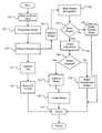
- FIG. 1shows one embodiment of the invention to improve the appearance of freehand drawn lines and shapes.
- FIG. 2shows an exemplary computing system that may used to implement the operations of the invention.
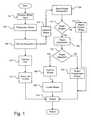
- FIG. 3illustrates the operational flow for the polyline recognition module 106 in FIG. 1 .
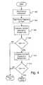
- FIG. 4shows the operational flow of evaluate operation 306 in FIG. 3 .
- FIG. 5illustrates an example of a segment pair to be evaluated as an angle segment by the operations of FIG. 4 .
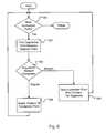
- FIG. 6illustrates the operations performed by the combine segments module 314 in FIG. 3 .
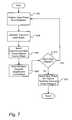
- FIG. 7shows the operations performed by the basic recognition module 108 in FIG. 1 .
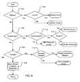
- FIG. 8illustrates the operational flow of the shape adjustment module 120 in FIG. 1 .
- the logical operations of the various embodiments of the present inventionare implemented (1) as a sequence of computer implemented steps, or acts, or as program modules running on a computing system and/or (2) as interconnected machine logic circuits or circuit modules within the computing system.
- the implementationis a matter of choice dependent on the performance requirements of the computing system implementing the invention. Accordingly, the logical operations making up the embodiments of the present invention described herein are referred to variously as operations, structural devices, steps, acts or modules. It will be recognized by one skilled in the art that these operations, structural devices, acts and modules may be implemented in software, in firmware, in special purpose digital logic, and any combination thereof without deviating from the spirit and scope of the present invention as recited within the claims attached hereto.
- the shape improvement operational flowbegins with receive operation 102 receiving the stroke input or, electronic ink input, data.
- Electronic inkrefers to stroke information in the form of sequential X,Y coordinate locations occupied by elements or points of the stroke.
- the strokeis entered by hand with pen or stylus on touch screen or by mouse or similar device controlling a cursor on a computer display screen.
- the electronic inkmay, but need not, include vector information (direction and velocity of stroke).
- electronic inkis a digital representation of a stroke as a series of X,Y point locations rather than an image representation of black and white picture elements (pels) on a page.
- the electronic ink representationmay be compressed, stored, transmitted and received.
- the electronic ink input datais made up of X,Y coordinates of points located along the path of the stroke.
- velocity informationmay also be a part of the electronic ink input data.
- a digitized input of X,Y coordinates from a mousewould provide X,Y coordinates every ⁇ fraction (1/40) ⁇ th of a second.
- the distance traveled by a stroke between two X,Y coordinate positions in a fixed interval of timegives the velocity of the stroke between the two positions.
- This stroke input information, the X,Y coordinates plus velocity informationis passed to a stroke preprocess operation 104 .
- the stroke preprocessing operationsmay include data filtering or data extrapolation and may make use of the X,Y coordinates and/or the velocity information.
- the output from the preprocessing operation 104is stroke information defined as a sequence of X,Y coordinates representing successive points along the line to be recognized and reshaped as a polyline or as a shape.
- This stroke informationis passed to a polyline line recognition operation 106 .
- Polylineas used herein refers to a line that may be visualized as one or more straight line segments sequentially connected together. If the successive segments are in-line the polyline would be a single straight line.
- the series of segmentsare not in-line they might form any contour such as a saw tooth, a hook, a right angle, an acute angle, an obtuse angle or sequential combinations thereof.
- a polylinecloses on itself it forms a shape.
- Polyline recognition module 106analyzes an input line as a series of segments that are either straight segments or angular segments.
- Straight segmentsare defined by two points, i.e., the X,Y coordinates of the point at each end of the segment.
- Angular segmentsare defined by three points, i.e., the outside end points of 2 straight segments and a common end point where the segments are connected at an angle to each other.
- the polyline recognition module 106sequentially analyzes all segments of the line and improves the sketch of the polyline into a sequence of straight segments.
- the polyline recognition moduleconcludes by testing whether the line closes on its self, i.e., forms a shape, or is open, i.e., multiple segments of a line.
- the operation flowpasses from the polyline recognition module 106 to improve shape operation 107 .
- Improve shape operation 107constructs the polyline shape from straight segments and angular segments determined during the polyline recognition module 106 .
- the polyline shapeis passed to the shape recognition operation 108 . If the polyline does not close on itself, the operation flow branches to the improve line operation 110 .
- the polyline recognition modulewill be described in more detail hereinafter in reference to FIG. 3 .
- the improve line operation 110receives the serial combined segments from the polyline recognition process and constructs the polyline from straight segments and angular segments determined during the polyline recognition module 106 .
- the improved line datais then passed to the locate operation 112 .
- Locate operation 112snaps the polyline to an X,Y grid on the virtual screen that maps to the computer display screen.
- the line data for the improved polylineis then output through output operation 114 to be rendered on the display screen.
- the handling of a closed polylinebegins at the basic shape recognition module 108 .
- the straight segment and angular segment information received from the polyline recognitionwhich defines a polyline shape, is analyzed to recognize the polyline shape as a basic reference shape such as ellipse, triangle, quadrangle, pentagonal, etc. If the polyline shape is recognized by basic shape recognition module 108 as being one shape from a set of basic ideal shapes, the polyline shape is improved by substituting for it a transformed basic ideal shape that is the most similar to the polyline shape.
- One embodiment of the basic shape recognition module 108is described hereinafter with reference to FIG. 7 .
- Basic shape test operation 116tests whether the shape was recognized and improved to the reference shape. If the shape was not distinct enough to be recognized, the operation flow branches NO to retain polyline shape operation 118 . Retain operation 118 simply retains the polyline shape from improve shape operation 107 and passes it to the output operation 114 to be rendered on the display screen. When the polyline shape is recognized and improved to a transformed basic shape, the basic shape test operation 116 will branch the operational flow YES to shape adjustment module 120 . The transformed basic shape from operation 108 is passed onto a shape adjustment module 120 .
- the shape adjustment module 120in one embodiment is a logical tree for comparing the transformed shape against more specific shapes that are logical extensions of the basic shape.
- the basic shapeis a quadrangle
- the transformed shapewill be tested against a parallelogram. If it is a parallelogram, it will be tested against a rectangle or square shape. If it is not a parallelogram, it will be tested against a trapezoid shape. If that fails, it will be compared to other four-segment shapes not having any sides parallel. If a specific shape is identified by this logical process, the transformed shape will be improved to this specific shape in improve shape operation 124 .
- the size of the tree and the number of reference common shapesis a matter of choice. An exemplary embodiment of the shape adjustment operation is shown in FIG. 8 and will be described in more detail hereinafter with reference to that figure.
- Adjustment test operation 122detects whether a specific shape was identified by the shape adjustment operation 120 . If the shape was not identified, the operation flow branches NO to the retain transformed shape operation 125 . The transformed basic shape is then retained and sent out by output operation 114 . If adjustment test operation 122 detects that the shape was identified as a specific shape, the operation flow branches YES to the improve shape operation 124 . Improve shape operation 124 receives the transformed shape segments and angles and improves the transformed shape identified during the shape adjustment operation. Once the shape has improved the operation proceeds to location operation 126 that snaps the improved shape to the grid of a virtual screen. The location and shape information is then output through output operation 114 to be rendered on the display screen.
- An exemplary system for implementing the inventionis the computing system 130 in FIG. 2 .
- the implementation of the inventioncould include two or more such computing systems configured in a server/client computing network.
- One exampleis shown and described in patent application Ser No. 10/123,733, entitled “Providing Hand-Written and Hand-Drawn Electronic Mail Service.”
- the inventioncould also be implemented in a stand alone computing system if the invention were applied to improving hand drawn shapes in an electronic document in a stand alone computing system.
- computing system 130In its most basic configuration, computing system 130 typically includes at least one processing unit 132 and memory 134 . Depending on the exact configuration and type of computing system, memory 134 may be volatile (such as RAM), non-volatile (such as ROM, flash memory, etc.) or some combination of the two. This most basic configuration is illustrated in FIG. 2 by dashed line 136 . Additionally, system 130 may also include additional storage (removable and/or non-removable) including, but not limited to, magnetic or optical disks or tape. Such additional storage is illustrated in FIG. 2 by removable storage 138 and non-removable storage 140 .
- additional storageremovable and/or non-removable
- Computer storage mediaincludes volatile and nonvolatile, removable and non-removable media implemented in any method or technology for storage of information such as computer readable instructions, data structures, program modules or other data.
- Memory 134 , removable storage 138 and non-removable storage 140are all examples of computer storage media.
- Computer storage mediaincludes, but is not limited to, RAM, ROM, EPROM, flash memory or other memory technology, CD-ROM, digital versatile disks (DVD) or other optical storage, magnetic cassettes, magnetic tape, magnetic disk storage or other magnetic storage devices, or any other medium which can be used to store the desired information and which can be accessed by system 130 . Any such computer storage media may be part of system 130 .
- System 130may also contain communications devices 142 that allow the system to communicate with other systems. Communications devices 142 send and receive communication media. Communication media typically embodies computer readable instructions, data structures, program modules or other data in a modulated data signal such as a carrier wave or other transport mechanism and includes any information delivery media.
- modulated data signalmeans a signal that has one or more of its characteristics set or changed in such a manner as to encode information in the signal.
- computer readable mediaincludes both storage media and communication media.
- System 130may also have input device(s) 144 such as keyboard, mouse, pen, stylus, voice input device, touch input device, etc.
- Output device(s) 146include display, speakers, printer, etc. All these devices are well known in the art and need not be discussed at length here.
- the polyline recognition modulebegins at set operation 302 that sets the entire input line or whole source line as the first source segment to be analyzed.
- Compare operation 304takes this freehand input line and compares it to a straight line. Compare operation 304 will generate a deviation value along the input line measuring the input line's deviation from the straight line.
- the two end points of the input lineare connected by a straight line, and the root mean square of the difference between the input line and the straight line along the length of the input line is computed. If this deviation value is not less than a threshold value K, deviation test operation 306 branches the operation flow NO to angle segment evaluate operation 307 .
- the operation flowbranches YES from deviation test operation 306 to define line segment operation 308 .
- Operation 308defines the line segment as a straight line between the X,Y coordinate positions of the end points of the line segment.
- Sequence operation 310receives the line segment definition from operation 308 and adds the line segment to line sequence data for the complete line.
- This whole line sequence datais composed of a combination of line segments and angle segments unless the source line is one straight line.
- End point X,Y addresses of sequential line and angle segments in the sequence of segmentsare the connection points to make up the complete line.
- Angle segmentsmay be defined as two line segments connected at a point of intersection with an angle other than 180° between them and having end points at the ends of the line segments opposite the point of intersection.
- an angle segmentcan be defined with three points or X,Y coordinate addresses—the point of intersection, or point of the angle within the angle segment, and the two end points of the angle segment away from the point of intersection.
- more segments test operation 312detects whether there are more segments to be processed or the entire source line has been processed. If the whole source line has a deviation value less than K, the whole source line is processed as a line segment, and there would be no more segments to process. In such a case the operation flow would branch NO to the combine segment operation 314 . Typically however, there will be additional segments to process, and the operation flow will branch YES to return to the compare source segment operation 304 . Compare operation 304 then compares the next source segment to be analyzed against a straight line for that segment.
- the angle segment evaluate operationanalyzes the source segment as an angle segment having two connected straight line segments connected at an angle to each other (where the angle is not 180°; i.e. the segments don't make a single straight line). If the source segment does not fit this model, the angle segment evaluate operation will not be successful. This could happen where there are multiple angles occurring in the source segment as for example in a saw tooth path or a gradually curving path. In other words, any path for the source segment that cannot be approximated by two straight lines connected at an angle to each other.
- Angle segment test operation 316tests whether the angle segment evaluation was a success. If the evaluation was successful, the operation flow branches YES to operation 318 to define the angle segment as described above. If the angle segment evaluation is not successful, the operational flow branches NO from test operation 316 to divide segment operation 320 . Divide segment operation 320 splits the source segment under evaluation into two equal segment parts, i.e. two new source segments. The operation flow branches back to operation 304 to compare the first of these new source segments to a straight line. Thus, the operation flow continues in FIG. 3 until all source segments have been processed and added to the line sequence data either as a line segment or an angle segment.
- the combined segments operation 314When there are no more segments to be processed as detected in more segments test operation 312 , the combined segments operation 314 combines all of the line segments and angle segments in the line sequence. The combined segments operation is described hereinafter with reference to FIG. 5 .
- a “closed line” test operation 322tests whether the combined segments have formed a closed line; i.e. the line has connected back to itself and thus enclosed a space. If a closed line is not detected then the operation flow branches NO to improve line operation 110 in FIG. 1 . If the combined segments operation has formed a closed line, then the operation flow branches YES from FIG. 3 closed line test operation 322 to improve shape operation 107 in FIG. 1 .
- the angle segment evaluation module or operation 307 and the angle segment test operation 316are shown in detail. This evaluate operation determines whether the source segment being examined is an angle segment.
- the operational flow of the angle segment evaluation modulebegins at find operation 402 finding the point of intersection for the angle segment.
- the find operation 402is accomplished by a test that compares (1) the straight-line distance from both end points to a test point to (2) the lengths along the actual angle segment portions from both end points to the test point.
- the straight-line distances from both end points to the test pointare computed.
- the straight-line distancesare designated P and R.
- the actual lengths of the angle segment portions from both end points to the test pointare computed based on the paths of the segment portions. These actual lengths are designated LP and LR.
- the testis repeated for all points along the angle segment. In this test, the point of intersection for the angle in the angle segment will be the test point where there is the minimum deviation between P and LP and a minimum deviation between R and LR.
- the expression (LP/P ⁇ 1) 2 +(LR/R ⁇ 1) 2will reach minimum value at the point of intersection for the angle in the angle segment.
- the operational flowpasses to split operation 404 that divides the source segment into two split segments at the point of intersection.
- Compare operation 406compares one of these split segments to a straight line.
- First split segment test operation 408tests whether the deviation for the first split segment from a straight line is less then K. If the deviation is not less than K, the angle segment under evaluation has more than one angular point of intersection. In other words the first split segment cannot be approximated as a straight line, and there must be at least one angular point in the first split segment in addition to the angle point already found. Therefore the angle segment evaluation has failed, and the operation flow branches NO to divide operation 320 in FIG. 3 where the source segment under test is divided into two new segments for further processing.
- the deviation of the first split segment of the source segmentis less than K, then this first segment on one side of the angle point is a straight line.
- Compare operation 410compares the second or other segment to a straight line. If the second segment is a straight line, the second segment split test operation 412 will detect a deviation less than K. In this event the angle segment evaluation has been successful as the preceding operations have detected that the source segment can be approximated by two straight segments intersecting at a single angle point. Now the operational flow branches YES from second split segment test operation 412 to define angle segment operation 318 (FIG. 3 ).
- the deviation detected by second split segment test operation 412will not be less than K.
- the source segmentmust have at least one angle point in the second split segment in addition to the angle point find between the first and second split segments. Now the angle segment evaluation and test has not been successful, i.e. has not confirmed an angle segment, and the operation flow branches NO to divide source segment operation 320 (FIG. 3 ).
- FIG. 6illustrates the combined segments operation 314 in FIG. 3 .
- the sequential segmentsmust be connected to create the reshaped line.
- the operational flowbegins with more connection points test operation 501 detecting whether there are more connection points in the line sequence data. If there are more connection points to be processed, the operation flow branches YES to find operation 502 which finds the connection point between sequential segments in the line sequence data. Find operation 502 searches for a common end point between two sequential segments. After the connection point between the segment pairs (adjacent segments) has been found then test operation 504 tests whether the connection is straight or angular.
- connectionis threshold in degrees (for example 180° ⁇ 3°) for determining that the connection is straight is a matter of choice and can be programmed into the test operation 504 to accomplish the appearance the user is looking for in reshaping the line.
- connection operation 506the connection point is simply dropped, and the end points for the combined segments are the outside end points of the segment pair away from the connection point. Effectively two adjacent segments, the segment pair, become one segment.
- adjust operation 508adjusts the position of the connection point between the segment pair, i.e. the two adjacent segments connected at the connection point.
- an operationwhich is the same as find operation 402 described with reference to FIGS. 4 and 5, is used by operation 508 to find the correct intersection point and thereby adjust the connection point between the two segments.
- the flowreturns to more connection points test operation 501 .
- the test operation 501detects that there are no more connection points to be handled.
- FIG. 7illustrates one embodiment of the basic shape recognition module 108 in FIG. 1 .
- These operationsbegin at operation 602 which retrieves a reference ideal shape from a database containing a plurality of reference ideal shapes.
- the reference ideal shapeswill be the basic shapes—ellipse, triangle, quadrangle, pentagon, etc.
- the retrieved, or reference, ideal shapeis transformed in transform operation 604 to a shape for comparison against the polyline shape to be recognized. This transformation is based on finding the best affine transformation which translates the points of the ideal shape into points of the polyline shape. For example, a quadrangle ideal shape would be adjusted in size and orientation of its segments to better match polyline shape such as a circle, triangle, rectangle or a trapezoid, etc.
- the transformed shapeis matched against a source shape and a similarity value is scored for the match.
- a quadrangle transformed shapewill compare poorly against a polyline shape that is a circle, a triangle, or any other shape not a quadrangle.
- More ideal shapes test operations 610then test whether there are more reference ideal shapes to be matched against the polyline shape. If there are, the operational flow returns to the retrieve operation 602 .
- Each source shapei.e. polyline shape, will be compared against all reference shapes such as, circle or elliptical, triangle, quadrangle, pentagon, etc.
- the operation flowbranches NO from test operation 610 to select operation 612 .
- the select operation 612selects the transformed ideal shape with the highest similarity value from all of the matches. This transformed shape is the output of the basic shape recognition operation 108 in the FIG. 1, and the operation flow in FIG. 7 returns to basic shape test operation 116 in FIG. 1 .
- FIG. 8shows the operation flow through tree logic for identifying the basic shape as a specific shape.
- the logical tree operation flowfirst detects the basic type or category of the transformed shape recognized at module 108 (FIG. 1 ).
- Ellipse test 702 , quadrangle test 704 , triangle test 706 and more shape categories 708are the trunk of the tree If the transformed basic shape was an ellipse, the operation flow branches to circle test operation 710 .
- Circle testidentifies the transformed shape as a circle or ellipse. If the transformed shape is a quadrangle, parallelogram test 712 passes the transformed shape to square test 714 if successful.
- Square testidentifies the shape as square or rectangle.
- test 712If test 712 is not successful, no specific shape is identified. Similarly if the transformed formed basic shape is a triangle, isosceles test 718 identifies the shape as an isosceles triangle, or no specific shape. If the transformed basic shape is not identified as a specific shape then the shape adjustment test 122 (FIG. 1) will detect failure. It will be appreciated by one skilled in the art that the branches in this logic are exemplary and any number of basic shapes and specific shapes could be used in many other embodiments of the invention.
- the shape adjustment modulewould test the angles or sides in the transformed shape and make automatic adjustments if the sides are within a few degrees of the X, Y grid or the angles are within a few degrees of angles in standard or common shapes. In other words, the angles might be adjusted to right angles or 60° angles or 45° angles.
- the parallelism of opposite sidesmight be compared or the parallelism of a side to a grid might be compared. If the sides or the side to grid were close to parallel, the sides or side to grid would be adjusted to be parallel.
- the ellipse and circlewould be processed somewhat differently from the above described embodiments of the basic shape recognition module.
- the ellipsewould be measured against the polyline shape along multiple circumferential points for example 30+ points. The difference between or separation between transformed ellipse and polyline shape would be measured to determine similarity.
Landscapes
- Engineering & Computer Science (AREA)
- Theoretical Computer Science (AREA)
- Physics & Mathematics (AREA)
- General Physics & Mathematics (AREA)
- General Engineering & Computer Science (AREA)
- Computer Vision & Pattern Recognition (AREA)
- Multimedia (AREA)
- Human Computer Interaction (AREA)
- Image Analysis (AREA)
Abstract
Description
Claims (17)
Priority Applications (6)
| Application Number | Priority Date | Filing Date | Title |
|---|---|---|---|
| US10/123,708US6658147B2 (en) | 2001-04-16 | 2002-04-15 | Reshaping freehand drawn lines and shapes in an electronic document |
| PCT/US2002/026221WO2003090153A1 (en) | 2002-04-15 | 2002-08-15 | Reshaping freehand drawn lines and shapes in an electronic document |
| AU2002367883AAU2002367883A1 (en) | 2002-04-15 | 2002-08-15 | Reshaping freehand drawn lines and shapes in an electronic document |
| US10/637,930US6876766B2 (en) | 2001-04-16 | 2003-08-08 | Reshaping freehand drawn lines and shapes in an electronic document |
| US10/637,957US7031526B2 (en) | 2001-04-16 | 2003-08-08 | Reshaping freehand drawn lines and shapes in an electronic document |
| US11/084,709US7450763B2 (en) | 2001-04-16 | 2005-03-18 | Reshaping freehand drawn lines and shapes in an electronic document |
Applications Claiming Priority (2)
| Application Number | Priority Date | Filing Date | Title |
|---|---|---|---|
| US28407501P | 2001-04-16 | 2001-04-16 | |
| US10/123,708US6658147B2 (en) | 2001-04-16 | 2002-04-15 | Reshaping freehand drawn lines and shapes in an electronic document |
Related Child Applications (2)
| Application Number | Title | Priority Date | Filing Date |
|---|---|---|---|
| US10/637,930DivisionUS6876766B2 (en) | 2001-04-16 | 2003-08-08 | Reshaping freehand drawn lines and shapes in an electronic document |
| US10/637,957ContinuationUS7031526B2 (en) | 2001-04-16 | 2003-08-08 | Reshaping freehand drawn lines and shapes in an electronic document |
Publications (2)
| Publication Number | Publication Date |
|---|---|
| US20020150297A1 US20020150297A1 (en) | 2002-10-17 |
| US6658147B2true US6658147B2 (en) | 2003-12-02 |
Family
ID=29248354
Family Applications (4)
| Application Number | Title | Priority Date | Filing Date |
|---|---|---|---|
| US10/123,708Expired - LifetimeUS6658147B2 (en) | 2001-04-16 | 2002-04-15 | Reshaping freehand drawn lines and shapes in an electronic document |
| US10/637,957Expired - LifetimeUS7031526B2 (en) | 2001-04-16 | 2003-08-08 | Reshaping freehand drawn lines and shapes in an electronic document |
| US10/637,930Expired - LifetimeUS6876766B2 (en) | 2001-04-16 | 2003-08-08 | Reshaping freehand drawn lines and shapes in an electronic document |
| US11/084,709Expired - LifetimeUS7450763B2 (en) | 2001-04-16 | 2005-03-18 | Reshaping freehand drawn lines and shapes in an electronic document |
Family Applications After (3)
| Application Number | Title | Priority Date | Filing Date |
|---|---|---|---|
| US10/637,957Expired - LifetimeUS7031526B2 (en) | 2001-04-16 | 2003-08-08 | Reshaping freehand drawn lines and shapes in an electronic document |
| US10/637,930Expired - LifetimeUS6876766B2 (en) | 2001-04-16 | 2003-08-08 | Reshaping freehand drawn lines and shapes in an electronic document |
| US11/084,709Expired - LifetimeUS7450763B2 (en) | 2001-04-16 | 2005-03-18 | Reshaping freehand drawn lines and shapes in an electronic document |
Country Status (3)
| Country | Link |
|---|---|
| US (4) | US6658147B2 (en) |
| AU (1) | AU2002367883A1 (en) |
| WO (1) | WO2003090153A1 (en) |
Cited By (38)
| Publication number | Priority date | Publication date | Assignee | Title |
|---|---|---|---|---|
| US20040109607A1 (en)* | 2001-04-16 | 2004-06-10 | Parascript Llp | Reshaping freehand drawn lines and shapes in an electronic document |
| US20070206024A1 (en)* | 2006-03-03 | 2007-09-06 | Ravishankar Rao | System and method for smooth pointing of objects during a presentation |
| US20100057816A1 (en)* | 2008-08-26 | 2010-03-04 | Eric May | Organizing Internet/Intranet research with interactive Dynamic Research Diagrams and Lists |
| US20120304131A1 (en)* | 2011-05-27 | 2012-11-29 | Jennifer Nan | Edge gesture |
| US8855375B2 (en) | 2012-01-12 | 2014-10-07 | Kofax, Inc. | Systems and methods for mobile image capture and processing |
| US8879846B2 (en) | 2009-02-10 | 2014-11-04 | Kofax, Inc. | Systems, methods and computer program products for processing financial documents |
| US8885229B1 (en) | 2013-05-03 | 2014-11-11 | Kofax, Inc. | Systems and methods for detecting and classifying objects in video captured using mobile devices |
| US8958605B2 (en) | 2009-02-10 | 2015-02-17 | Kofax, Inc. | Systems, methods and computer program products for determining document validity |
| US9058580B1 (en) | 2012-01-12 | 2015-06-16 | Kofax, Inc. | Systems and methods for identification document processing and business workflow integration |
| US9058515B1 (en) | 2012-01-12 | 2015-06-16 | Kofax, Inc. | Systems and methods for identification document processing and business workflow integration |
| US9137417B2 (en) | 2005-03-24 | 2015-09-15 | Kofax, Inc. | Systems and methods for processing video data |
| US9141926B2 (en) | 2013-04-23 | 2015-09-22 | Kofax, Inc. | Smart mobile application development platform |
| US9208536B2 (en) | 2013-09-27 | 2015-12-08 | Kofax, Inc. | Systems and methods for three dimensional geometric reconstruction of captured image data |
| US9229918B2 (en) | 2010-12-23 | 2016-01-05 | Microsoft Technology Licensing, Llc | Presenting an application change through a tile |
| US9311531B2 (en) | 2013-03-13 | 2016-04-12 | Kofax, Inc. | Systems and methods for classifying objects in digital images captured using mobile devices |
| US9329774B2 (en) | 2011-05-27 | 2016-05-03 | Microsoft Technology Licensing, Llc | Switching back to a previously-interacted-with application |
| US9355312B2 (en) | 2013-03-13 | 2016-05-31 | Kofax, Inc. | Systems and methods for classifying objects in digital images captured using mobile devices |
| US9386235B2 (en) | 2013-11-15 | 2016-07-05 | Kofax, Inc. | Systems and methods for generating composite images of long documents using mobile video data |
| US9396388B2 (en) | 2009-02-10 | 2016-07-19 | Kofax, Inc. | Systems, methods and computer program products for determining document validity |
| US9483794B2 (en) | 2012-01-12 | 2016-11-01 | Kofax, Inc. | Systems and methods for identification document processing and business workflow integration |
| US9535597B2 (en) | 2011-05-27 | 2017-01-03 | Microsoft Technology Licensing, Llc | Managing an immersive interface in a multi-application immersive environment |
| US9576272B2 (en) | 2009-02-10 | 2017-02-21 | Kofax, Inc. | Systems, methods and computer program products for determining document validity |
| US9658766B2 (en) | 2011-05-27 | 2017-05-23 | Microsoft Technology Licensing, Llc | Edge gesture |
| US9747269B2 (en) | 2009-02-10 | 2017-08-29 | Kofax, Inc. | Smart optical input/output (I/O) extension for context-dependent workflows |
| US9760788B2 (en) | 2014-10-30 | 2017-09-12 | Kofax, Inc. | Mobile document detection and orientation based on reference object characteristics |
| US9767354B2 (en) | 2009-02-10 | 2017-09-19 | Kofax, Inc. | Global geographic information retrieval, validation, and normalization |
| US9769354B2 (en) | 2005-03-24 | 2017-09-19 | Kofax, Inc. | Systems and methods of processing scanned data |
| US9779296B1 (en) | 2016-04-01 | 2017-10-03 | Kofax, Inc. | Content-based detection and three dimensional geometric reconstruction of objects in image and video data |
| US10146795B2 (en) | 2012-01-12 | 2018-12-04 | Kofax, Inc. | Systems and methods for mobile image capture and processing |
| US10242285B2 (en) | 2015-07-20 | 2019-03-26 | Kofax, Inc. | Iterative recognition-guided thresholding and data extraction |
| US10254955B2 (en) | 2011-09-10 | 2019-04-09 | Microsoft Technology Licensing, Llc | Progressively indicating new content in an application-selectable user interface |
| US10303325B2 (en) | 2011-05-27 | 2019-05-28 | Microsoft Technology Licensing, Llc | Multi-application environment |
| US10579250B2 (en) | 2011-09-01 | 2020-03-03 | Microsoft Technology Licensing, Llc | Arranging tiles |
| US10803350B2 (en) | 2017-11-30 | 2020-10-13 | Kofax, Inc. | Object detection and image cropping using a multi-detector approach |
| US10884979B2 (en) | 2016-09-02 | 2021-01-05 | FutureVault Inc. | Automated document filing and processing methods and systems |
| US10969944B2 (en) | 2010-12-23 | 2021-04-06 | Microsoft Technology Licensing, Llc | Application reporting in an application-selectable user interface |
| US11120056B2 (en) | 2016-09-02 | 2021-09-14 | FutureVault Inc. | Systems and methods for sharing documents |
| US11475074B2 (en) | 2016-09-02 | 2022-10-18 | FutureVault Inc. | Real-time document filtering systems and methods |
Families Citing this family (32)
| Publication number | Priority date | Publication date | Assignee | Title |
|---|---|---|---|---|
| US7401299B2 (en)* | 2001-09-05 | 2008-07-15 | Autodesk, Inc. | Method and apparatus for providing a presumptive drafting solution |
| US7549131B2 (en)* | 2002-12-31 | 2009-06-16 | Apple Inc. | Method of controlling movement of a cursor on a screen and a computer readable medium containing such a method as a program code |
| JP2006003425A (en)* | 2004-06-15 | 2006-01-05 | Canon Inc | Image display device and image display system |
| US7515752B2 (en) | 2004-08-27 | 2009-04-07 | Corel Corporation | Sketch recognition and enhancement |
| ATE534978T1 (en)* | 2005-07-26 | 2011-12-15 | Decarta Inc | GENERALIZATION OF FEATURES IN A DIGITAL MAP |
| US7774722B2 (en)* | 2006-01-31 | 2010-08-10 | Microsoft Corporation | Creation and manipulation of canvases based on ink strokes |
| AU2006252025B2 (en)* | 2006-12-13 | 2012-10-04 | Canon Kabushiki Kaisha | Recognition of parameterised shapes from document images |
| AU2006252019B2 (en)* | 2006-12-13 | 2012-06-28 | Canon Kabushiki Kaisha | Method and Apparatus for Dynamic Connector Analysis |
| US8094939B2 (en)* | 2007-06-26 | 2012-01-10 | Microsoft Corporation | Digital ink-based search |
| US8315482B2 (en)* | 2007-06-26 | 2012-11-20 | Microsoft Corporation | Integrated platform for user input of digital ink |
| WO2009021078A1 (en)* | 2007-08-06 | 2009-02-12 | Decarta Inc. | Generalization of features in a digital map using round number coordinates |
| US20100171754A1 (en)* | 2009-01-07 | 2010-07-08 | Microsoft Corporation | Converting digital ink to shapes and text |
| US20120216113A1 (en) | 2011-02-18 | 2012-08-23 | Google Inc. | Touch gestures for text-entry operations |
| JP2012256270A (en)* | 2011-06-10 | 2012-12-27 | Sony Corp | Information processor, program, and information processing method |
| US9098186B1 (en) | 2012-04-05 | 2015-08-04 | Amazon Technologies, Inc. | Straight line gesture recognition and rendering |
| US9373049B1 (en)* | 2012-04-05 | 2016-06-21 | Amazon Technologies, Inc. | Straight line gesture recognition and rendering |
| US9007390B2 (en) | 2012-05-15 | 2015-04-14 | Evernote Corporation | Creation and manipulation of hand drawn objects with automatic grouping |
| US20130321313A1 (en)* | 2012-05-31 | 2013-12-05 | Htc Corporation | Method, apparatus and computer program product for cropping screen frame |
| KR102150289B1 (en) | 2012-08-30 | 2020-09-01 | 삼성전자주식회사 | User interface appratus in a user terminal and method therefor |
| US20140337705A1 (en)* | 2013-05-10 | 2014-11-13 | Successfactors, Inc. | System and method for annotations |
| JP2014235452A (en)* | 2013-05-30 | 2014-12-15 | 株式会社東芝 | Shaping device |
| US20150220504A1 (en)* | 2014-02-04 | 2015-08-06 | Adobe Systems Incorporated | Visual Annotations for Objects |
| US9747713B2 (en)* | 2014-04-09 | 2017-08-29 | Adobe Systems Incorporated | Performing editing actions on recent drawing marks |
| US10275050B2 (en) | 2014-05-23 | 2019-04-30 | Microsoft Technology Licensing, Llc | Ink for a shared interactive space |
| TWI557287B (en)* | 2015-09-21 | 2016-11-11 | Zeng Hsing Ind Co Ltd | Handwriting Needle Identification Method and Its Identification System |
| US10121232B1 (en)* | 2015-12-23 | 2018-11-06 | Evernote Corporation | Visual quality of photographs with handwritten content |
| US9977956B2 (en)* | 2016-07-29 | 2018-05-22 | Konica Minolta Laboratory U.S.A., Inc. | Selecting primary groups during production of a flowchart object from an image |
| US10521937B2 (en)* | 2017-02-28 | 2019-12-31 | Corel Corporation | Vector graphics based live sketching methods and systems |
| CN107730577B (en)* | 2017-11-08 | 2021-08-31 | 米哈游科技(上海)有限公司 | Line-hooking rendering method, device, equipment and medium |
| CN110598634B (en)* | 2019-09-12 | 2020-08-07 | 山东文多网络科技有限公司 | Machine room sketch identification method and device based on graph example library |
| LU101625B1 (en)* | 2020-02-03 | 2021-08-03 | Microsoft Technology Licensing Llc | Systems and methods for grid-aligned inking |
| CN113888546B (en)* | 2021-09-01 | 2025-01-24 | 浙江大华技术股份有限公司 | Hand-drawn graphics regularization method, electronic device and storage medium |
Citations (6)
| Publication number | Priority date | Publication date | Assignee | Title |
|---|---|---|---|---|
| US4933865A (en)* | 1986-12-20 | 1990-06-12 | Fujitsu Limited | Apparatus for recognition of drawn shapes or view types for automatic drawing input in CAD system |
| US5425109A (en)* | 1992-10-22 | 1995-06-13 | Mutoh Industries Ltd. | System for identifying freehand drawings |
| US5636297A (en)* | 1992-09-10 | 1997-06-03 | Microsoft Corporation | Method and system for recognizing a graphic object's shape, line style, and fill pattern in a pen environment |
| US5926567A (en)* | 1995-03-01 | 1999-07-20 | Compaq Computer Corporation | Method and apparatus for storing and rapidly displaying graphic data |
| US6057845A (en)* | 1997-11-14 | 2000-05-02 | Sensiva, Inc. | System, method, and apparatus for generation and recognizing universal commands |
| US6424746B1 (en)* | 1997-10-28 | 2002-07-23 | Ricoh Company, Ltd. | Figure classifying method, figure classifying system, feature extracting method for figure classification, method for producing table for figure classification, information recording medium, method for evaluating degree of similarity or degree of difference between figures, figure normalizing method, and method for determining correspondence between figures |
Family Cites Families (16)
| Publication number | Priority date | Publication date | Assignee | Title |
|---|---|---|---|---|
| JPS60136892A (en)* | 1983-12-26 | 1985-07-20 | Hitachi Ltd | On-line recognition device of hand written graphic |
| US5424109A (en)* | 1984-08-09 | 1995-06-13 | Atlantic Research Corporation | Hybrid dual fiber matrix densified structure and method for making same |
| US5003495A (en)* | 1987-07-27 | 1991-03-26 | Visual Understanding Systems, Inc. | Method and apparatus for scanning, storing and reproducing artwork |
| DE69428675T2 (en)* | 1993-12-30 | 2002-05-08 | Xerox Corp | Apparatus and method for supporting an implicit structuring of free-form lists, overviews, texts, tables and diagrams in an input system and editing system based on hand signals |
| JP2939147B2 (en)* | 1994-12-29 | 1999-08-25 | シャープ株式会社 | Handwritten character input display device and method |
| US5987173A (en)* | 1995-03-27 | 1999-11-16 | Nippon Steel Corporation | Interactive drawing recognition processing method and apparatus thereof |
| US5835640A (en)* | 1995-05-03 | 1998-11-10 | Seiko Epson Corporation | Method and apparatus for identifying and fixing horizontal and vertical lines in digitized images |
| US6044165A (en)* | 1995-06-15 | 2000-03-28 | California Institute Of Technology | Apparatus and method for tracking handwriting from visual input |
| US6266444B1 (en)* | 1996-10-11 | 2001-07-24 | Canon Kabushiki Kaisha | Character processing apparatus and method therefor |
| US6212420B1 (en)* | 1998-03-13 | 2001-04-03 | University Of Iowa Research Foundation | Curved cross-section based system and method for gastrointestinal tract unraveling |
| US7091959B1 (en)* | 1999-03-31 | 2006-08-15 | Advanced Digital Systems, Inc. | System, computer program product, computing device, and associated methods for form identification and information manipulation |
| US6529641B1 (en)* | 1999-10-29 | 2003-03-04 | Eastman Kodak Company | Method for deskewing a scanned text image |
| JP4066585B2 (en)* | 2000-01-24 | 2008-03-26 | 株式会社日立製作所 | Shape creation method |
| US6658147B2 (en)* | 2001-04-16 | 2003-12-02 | Parascript Llc | Reshaping freehand drawn lines and shapes in an electronic document |
| US20030015355A1 (en)* | 2001-07-18 | 2003-01-23 | Chi-Ti Kao | Method for modifying handwriting locus of handwriting-input device |
| US7613539B2 (en)* | 2006-05-09 | 2009-11-03 | Inus Technology, Inc. | System and method for mesh and body hybrid modeling using 3D scan data |
- 2002
- 2002-04-15USUS10/123,708patent/US6658147B2/ennot_activeExpired - Lifetime
- 2002-08-15WOPCT/US2002/026221patent/WO2003090153A1/ennot_activeApplication Discontinuation
- 2002-08-15AUAU2002367883Apatent/AU2002367883A1/ennot_activeAbandoned
- 2003
- 2003-08-08USUS10/637,957patent/US7031526B2/ennot_activeExpired - Lifetime
- 2003-08-08USUS10/637,930patent/US6876766B2/ennot_activeExpired - Lifetime
- 2005
- 2005-03-18USUS11/084,709patent/US7450763B2/ennot_activeExpired - Lifetime
Patent Citations (6)
| Publication number | Priority date | Publication date | Assignee | Title |
|---|---|---|---|---|
| US4933865A (en)* | 1986-12-20 | 1990-06-12 | Fujitsu Limited | Apparatus for recognition of drawn shapes or view types for automatic drawing input in CAD system |
| US5636297A (en)* | 1992-09-10 | 1997-06-03 | Microsoft Corporation | Method and system for recognizing a graphic object's shape, line style, and fill pattern in a pen environment |
| US5425109A (en)* | 1992-10-22 | 1995-06-13 | Mutoh Industries Ltd. | System for identifying freehand drawings |
| US5926567A (en)* | 1995-03-01 | 1999-07-20 | Compaq Computer Corporation | Method and apparatus for storing and rapidly displaying graphic data |
| US6424746B1 (en)* | 1997-10-28 | 2002-07-23 | Ricoh Company, Ltd. | Figure classifying method, figure classifying system, feature extracting method for figure classification, method for producing table for figure classification, information recording medium, method for evaluating degree of similarity or degree of difference between figures, figure normalizing method, and method for determining correspondence between figures |
| US6057845A (en)* | 1997-11-14 | 2000-05-02 | Sensiva, Inc. | System, method, and apparatus for generation and recognizing universal commands |
Non-Patent Citations (2)
| Title |
|---|
| http://www.eetimes.com/storyOEG20001127S0034; E-commerce comes to portable apps; Greg Simon et al.; EE Times; Nov. 27, 2000. |
| PCT International Search Report for PCT/US02/26221. |
Cited By (63)
| Publication number | Priority date | Publication date | Assignee | Title |
|---|---|---|---|---|
| US20050244058A1 (en)* | 2001-04-16 | 2005-11-03 | Boris Gorbatov | Reshaping freehand drawn lines and shapes in an electronic document |
| US7031526B2 (en)* | 2001-04-16 | 2006-04-18 | Evemote Corporation | Reshaping freehand drawn lines and shapes in an electronic document |
| US7450763B2 (en)* | 2001-04-16 | 2008-11-11 | Evernote Corp. | Reshaping freehand drawn lines and shapes in an electronic document |
| US20040109607A1 (en)* | 2001-04-16 | 2004-06-10 | Parascript Llp | Reshaping freehand drawn lines and shapes in an electronic document |
| US9137417B2 (en) | 2005-03-24 | 2015-09-15 | Kofax, Inc. | Systems and methods for processing video data |
| US9769354B2 (en) | 2005-03-24 | 2017-09-19 | Kofax, Inc. | Systems and methods of processing scanned data |
| US20070206024A1 (en)* | 2006-03-03 | 2007-09-06 | Ravishankar Rao | System and method for smooth pointing of objects during a presentation |
| US20100057816A1 (en)* | 2008-08-26 | 2010-03-04 | Eric May | Organizing Internet/Intranet research with interactive Dynamic Research Diagrams and Lists |
| US9396388B2 (en) | 2009-02-10 | 2016-07-19 | Kofax, Inc. | Systems, methods and computer program products for determining document validity |
| US8879846B2 (en) | 2009-02-10 | 2014-11-04 | Kofax, Inc. | Systems, methods and computer program products for processing financial documents |
| US9767354B2 (en) | 2009-02-10 | 2017-09-19 | Kofax, Inc. | Global geographic information retrieval, validation, and normalization |
| US8958605B2 (en) | 2009-02-10 | 2015-02-17 | Kofax, Inc. | Systems, methods and computer program products for determining document validity |
| US9747269B2 (en) | 2009-02-10 | 2017-08-29 | Kofax, Inc. | Smart optical input/output (I/O) extension for context-dependent workflows |
| US9576272B2 (en) | 2009-02-10 | 2017-02-21 | Kofax, Inc. | Systems, methods and computer program products for determining document validity |
| US11126333B2 (en) | 2010-12-23 | 2021-09-21 | Microsoft Technology Licensing, Llc | Application reporting in an application-selectable user interface |
| US9229918B2 (en) | 2010-12-23 | 2016-01-05 | Microsoft Technology Licensing, Llc | Presenting an application change through a tile |
| US10969944B2 (en) | 2010-12-23 | 2021-04-06 | Microsoft Technology Licensing, Llc | Application reporting in an application-selectable user interface |
| US20120304131A1 (en)* | 2011-05-27 | 2012-11-29 | Jennifer Nan | Edge gesture |
| US9658766B2 (en) | 2011-05-27 | 2017-05-23 | Microsoft Technology Licensing, Llc | Edge gesture |
| US10303325B2 (en) | 2011-05-27 | 2019-05-28 | Microsoft Technology Licensing, Llc | Multi-application environment |
| US9535597B2 (en) | 2011-05-27 | 2017-01-03 | Microsoft Technology Licensing, Llc | Managing an immersive interface in a multi-application immersive environment |
| US11698721B2 (en) | 2011-05-27 | 2023-07-11 | Microsoft Technology Licensing, Llc | Managing an immersive interface in a multi-application immersive environment |
| US9329774B2 (en) | 2011-05-27 | 2016-05-03 | Microsoft Technology Licensing, Llc | Switching back to a previously-interacted-with application |
| US10579250B2 (en) | 2011-09-01 | 2020-03-03 | Microsoft Technology Licensing, Llc | Arranging tiles |
| US10254955B2 (en) | 2011-09-10 | 2019-04-09 | Microsoft Technology Licensing, Llc | Progressively indicating new content in an application-selectable user interface |
| US9483794B2 (en) | 2012-01-12 | 2016-11-01 | Kofax, Inc. | Systems and methods for identification document processing and business workflow integration |
| US10664919B2 (en) | 2012-01-12 | 2020-05-26 | Kofax, Inc. | Systems and methods for mobile image capture and processing |
| US8855375B2 (en) | 2012-01-12 | 2014-10-07 | Kofax, Inc. | Systems and methods for mobile image capture and processing |
| US8879120B2 (en) | 2012-01-12 | 2014-11-04 | Kofax, Inc. | Systems and methods for mobile image capture and processing |
| US9342742B2 (en) | 2012-01-12 | 2016-05-17 | Kofax, Inc. | Systems and methods for mobile image capture and processing |
| US10657600B2 (en) | 2012-01-12 | 2020-05-19 | Kofax, Inc. | Systems and methods for mobile image capture and processing |
| US9514357B2 (en) | 2012-01-12 | 2016-12-06 | Kofax, Inc. | Systems and methods for mobile image capture and processing |
| US8971587B2 (en) | 2012-01-12 | 2015-03-03 | Kofax, Inc. | Systems and methods for mobile image capture and processing |
| US9165188B2 (en) | 2012-01-12 | 2015-10-20 | Kofax, Inc. | Systems and methods for mobile image capture and processing |
| US8989515B2 (en) | 2012-01-12 | 2015-03-24 | Kofax, Inc. | Systems and methods for mobile image capture and processing |
| US9165187B2 (en) | 2012-01-12 | 2015-10-20 | Kofax, Inc. | Systems and methods for mobile image capture and processing |
| US9058580B1 (en) | 2012-01-12 | 2015-06-16 | Kofax, Inc. | Systems and methods for identification document processing and business workflow integration |
| US9158967B2 (en) | 2012-01-12 | 2015-10-13 | Kofax, Inc. | Systems and methods for mobile image capture and processing |
| US10146795B2 (en) | 2012-01-12 | 2018-12-04 | Kofax, Inc. | Systems and methods for mobile image capture and processing |
| US9058515B1 (en) | 2012-01-12 | 2015-06-16 | Kofax, Inc. | Systems and methods for identification document processing and business workflow integration |
| US9355312B2 (en) | 2013-03-13 | 2016-05-31 | Kofax, Inc. | Systems and methods for classifying objects in digital images captured using mobile devices |
| US9311531B2 (en) | 2013-03-13 | 2016-04-12 | Kofax, Inc. | Systems and methods for classifying objects in digital images captured using mobile devices |
| US9996741B2 (en) | 2013-03-13 | 2018-06-12 | Kofax, Inc. | Systems and methods for classifying objects in digital images captured using mobile devices |
| US10127441B2 (en) | 2013-03-13 | 2018-11-13 | Kofax, Inc. | Systems and methods for classifying objects in digital images captured using mobile devices |
| US9754164B2 (en) | 2013-03-13 | 2017-09-05 | Kofax, Inc. | Systems and methods for classifying objects in digital images captured using mobile devices |
| US10146803B2 (en) | 2013-04-23 | 2018-12-04 | Kofax, Inc | Smart mobile application development platform |
| US9141926B2 (en) | 2013-04-23 | 2015-09-22 | Kofax, Inc. | Smart mobile application development platform |
| US9584729B2 (en) | 2013-05-03 | 2017-02-28 | Kofax, Inc. | Systems and methods for improving video captured using mobile devices |
| US8885229B1 (en) | 2013-05-03 | 2014-11-11 | Kofax, Inc. | Systems and methods for detecting and classifying objects in video captured using mobile devices |
| US9253349B2 (en) | 2013-05-03 | 2016-02-02 | Kofax, Inc. | Systems and methods for detecting and classifying objects in video captured using mobile devices |
| US9946954B2 (en) | 2013-09-27 | 2018-04-17 | Kofax, Inc. | Determining distance between an object and a capture device based on captured image data |
| US9208536B2 (en) | 2013-09-27 | 2015-12-08 | Kofax, Inc. | Systems and methods for three dimensional geometric reconstruction of captured image data |
| US9747504B2 (en) | 2013-11-15 | 2017-08-29 | Kofax, Inc. | Systems and methods for generating composite images of long documents using mobile video data |
| US9386235B2 (en) | 2013-11-15 | 2016-07-05 | Kofax, Inc. | Systems and methods for generating composite images of long documents using mobile video data |
| US9760788B2 (en) | 2014-10-30 | 2017-09-12 | Kofax, Inc. | Mobile document detection and orientation based on reference object characteristics |
| US10242285B2 (en) | 2015-07-20 | 2019-03-26 | Kofax, Inc. | Iterative recognition-guided thresholding and data extraction |
| US9779296B1 (en) | 2016-04-01 | 2017-10-03 | Kofax, Inc. | Content-based detection and three dimensional geometric reconstruction of objects in image and video data |
| US10884979B2 (en) | 2016-09-02 | 2021-01-05 | FutureVault Inc. | Automated document filing and processing methods and systems |
| US11775866B2 (en) | 2016-09-02 | 2023-10-03 | Future Vault Inc. | Automated document filing and processing methods and systems |
| US11120056B2 (en) | 2016-09-02 | 2021-09-14 | FutureVault Inc. | Systems and methods for sharing documents |
| US11475074B2 (en) | 2016-09-02 | 2022-10-18 | FutureVault Inc. | Real-time document filtering systems and methods |
| US10803350B2 (en) | 2017-11-30 | 2020-10-13 | Kofax, Inc. | Object detection and image cropping using a multi-detector approach |
| US11062176B2 (en) | 2017-11-30 | 2021-07-13 | Kofax, Inc. | Object detection and image cropping using a multi-detector approach |
Also Published As
| Publication number | Publication date |
|---|---|
| US7031526B2 (en) | 2006-04-18 |
| US20040047506A1 (en) | 2004-03-11 |
| US20050244058A1 (en) | 2005-11-03 |
| US6876766B2 (en) | 2005-04-05 |
| WO2003090153A1 (en) | 2003-10-30 |
| AU2002367883A1 (en) | 2003-11-03 |
| US20020150297A1 (en) | 2002-10-17 |
| US20040109607A1 (en) | 2004-06-10 |
| US7450763B2 (en) | 2008-11-11 |
Similar Documents
| Publication | Publication Date | Title |
|---|---|---|
| US6658147B2 (en) | Reshaping freehand drawn lines and shapes in an electronic document | |
| US7027651B2 (en) | Geometric hashing method for model-based recognition of an object | |
| US9092697B2 (en) | Image recognition system and method for identifying similarities in different images | |
| EP3474191A1 (en) | Method and device for constructing a table including information on a pooling type and testing method and testing device using the same | |
| CN112418180B (en) | Table data extraction method, device, equipment and computer storage medium | |
| EP2064652A1 (en) | Method of image processing | |
| US20110299735A1 (en) | Method of using structural models for optical recognition | |
| CN111368632A (en) | Signature identification method and device | |
| US11972610B2 (en) | Multi-pass object tracking system utilizing single object tracking in a multi object tracking use case for higher accuracy | |
| US8660371B2 (en) | Accuracy of recognition by means of a combination of classifiers | |
| US6901171B1 (en) | Methods and apparatuses for refining groupings of edge points that represent a contour in an image | |
| US20100098301A1 (en) | Method and Device for Recognizing a Face and Face Recognition Module | |
| CN118334672A (en) | Electronic price tag identification method and device | |
| CN115035129A (en) | Goods identification method and device, electronic equipment and storage medium | |
| US6697535B1 (en) | Method for refining a parameter of a contour in an image | |
| CN111753719A (en) | Fingerprint identification method and device | |
| US20230215033A1 (en) | Convex geometry image capture | |
| JP4570995B2 (en) | MATCHING METHOD, MATCHING DEVICE, AND PROGRAM | |
| JPH06111073A (en) | Handwritten information recognizing device | |
| US10796197B2 (en) | Automatic method and system for similar images and image fragments detection basing on image content | |
| Salehin et al. | Conics detection method based on pascal's theorem | |
| US20050207653A1 (en) | Method for analysis of line objects | |
| CN111626364B (en) | Hand gesture image classification method, device, computer equipment and storage medium | |
| WO2025065471A1 (en) | Computer-implemented method of detecting fingertip in image, apparatus for detecting fingertip in image, and computer-program product | |
| Wolin et al. | Eliminating False Positives during Corner Finding by Merging Similar Segments. |
Legal Events
| Date | Code | Title | Description |
|---|---|---|---|
| AS | Assignment | Owner name:PARASCRIPT LLC, COLORADO Free format text:ASSIGNMENT OF ASSIGNORS INTEREST;ASSIGNORS:GORBATOV, BORIS;LOSSEV, ILIA;REEL/FRAME:012816/0198 Effective date:20020412 | |
| STCF | Information on status: patent grant | Free format text:PATENTED CASE | |
| CC | Certificate of correction | ||
| FEPP | Fee payment procedure | Free format text:PAYOR NUMBER ASSIGNED (ORIGINAL EVENT CODE: ASPN); ENTITY STATUS OF PATENT OWNER: LARGE ENTITY | |
| AS | Assignment | Owner name:EVERNOTE CORPORATION, CALIFORNIA Free format text:ASSIGNMENT OF ASSIGNORS INTEREST;ASSIGNOR:PARASCRIPT, LLC;REEL/FRAME:017214/0818 Effective date:20060224 | |
| FPAY | Fee payment | Year of fee payment:4 | |
| FPAY | Fee payment | Year of fee payment:8 | |
| FPAY | Fee payment | Year of fee payment:12 | |
| AS | Assignment | Owner name:SILICON VALLEY BANK, CALIFORNIA Free format text:SECURITY AGREEMENT;ASSIGNOR:EVERNOTE CORPORATION;REEL/FRAME:040192/0720 Effective date:20160930 | |
| AS | Assignment | Owner name:HERCULES CAPITAL, INC., AS AGENT, CALIFORNIA Free format text:SECURITY INTEREST;ASSIGNORS:EVERNOTE CORPORATION;EVERNOTE GMBH;REEL/FRAME:040240/0945 Effective date:20160930 | |
| AS | Assignment | Owner name:EAST WEST BANK, CALIFORNIA Free format text:SECURITY INTEREST;ASSIGNOR:EVERNOTE CORPORATION;REEL/FRAME:054113/0876 Effective date:20201019 | |
| AS | Assignment | Owner name:EVERNOTE CORPORATION, CALIFORNIA Free format text:INTELLECTUAL PROPERTY SECURITY AGREEMENT TERMINATION AT R/F 040192/0720;ASSIGNOR:SILICON VALLEY BANK;REEL/FRAME:054145/0452 Effective date:20201019 Owner name:EVERNOTE GMBH, CALIFORNIA Free format text:INTELLECTUAL PROPERTY SECURITY AGREEMENT TERMINATION AT R/F 040240/0945;ASSIGNOR:HERCULES CAPITAL, INC.;REEL/FRAME:054213/0234 Effective date:20201019 Owner name:EVERNOTE CORPORATION, CALIFORNIA Free format text:INTELLECTUAL PROPERTY SECURITY AGREEMENT TERMINATION AT R/F 040240/0945;ASSIGNOR:HERCULES CAPITAL, INC.;REEL/FRAME:054213/0234 Effective date:20201019 | |
| AS | Assignment | Owner name:MUFG UNION BANK, N.A., CALIFORNIA Free format text:SECURITY INTEREST;ASSIGNOR:EVERNOTE CORPORATION;REEL/FRAME:057722/0876 Effective date:20211001 | |
| AS | Assignment | Owner name:EVERNOTE CORPORATION, CALIFORNIA Free format text:RELEASE BY SECURED PARTY;ASSIGNOR:EAST WEST BANK;REEL/FRAME:057852/0078 Effective date:20211001 | |
| AS | Assignment | Owner name:EVERNOTE CORPORATION, CALIFORNIA Free format text:RELEASE BY SECURED PARTY;ASSIGNOR:MUFG BANK, LTD.;REEL/FRAME:063116/0260 Effective date:20230103 |