US6657607B1 - Liquid crystal flat panel display with enhanced backlight brightness and specially selected light sources - Google Patents
Liquid crystal flat panel display with enhanced backlight brightness and specially selected light sourcesDownload PDFInfo
- Publication number
- US6657607B1 US6657607B1US09/811,988US81198801AUS6657607B1US 6657607 B1US6657607 B1US 6657607B1US 81198801 AUS81198801 AUS 81198801AUS 6657607 B1US6657607 B1US 6657607B1
- Authority
- US
- United States
- Prior art keywords
- light
- color temperature
- flat panel
- panel display
- light pipe
- Prior art date
- Legal status (The legal status is an assumption and is not a legal conclusion. Google has not performed a legal analysis and makes no representation as to the accuracy of the status listed.)
- Expired - Lifetime, expires
Links
Images


Classifications
- G—PHYSICS
- G02—OPTICS
- G02B—OPTICAL ELEMENTS, SYSTEMS OR APPARATUS
- G02B6/00—Light guides; Structural details of arrangements comprising light guides and other optical elements, e.g. couplings
- G02B6/0001—Light guides; Structural details of arrangements comprising light guides and other optical elements, e.g. couplings specially adapted for lighting devices or systems
- G02B6/0011—Light guides; Structural details of arrangements comprising light guides and other optical elements, e.g. couplings specially adapted for lighting devices or systems the light guides being planar or of plate-like form
- G02B6/0066—Light guides; Structural details of arrangements comprising light guides and other optical elements, e.g. couplings specially adapted for lighting devices or systems the light guides being planar or of plate-like form characterised by the light source being coupled to the light guide
- G02B6/0068—Arrangements of plural sources, e.g. multi-colour light sources
- G—PHYSICS
- G02—OPTICS
- G02F—OPTICAL DEVICES OR ARRANGEMENTS FOR THE CONTROL OF LIGHT BY MODIFICATION OF THE OPTICAL PROPERTIES OF THE MEDIA OF THE ELEMENTS INVOLVED THEREIN; NON-LINEAR OPTICS; FREQUENCY-CHANGING OF LIGHT; OPTICAL LOGIC ELEMENTS; OPTICAL ANALOGUE/DIGITAL CONVERTERS
- G02F1/00—Devices or arrangements for the control of the intensity, colour, phase, polarisation or direction of light arriving from an independent light source, e.g. switching, gating or modulating; Non-linear optics
- G02F1/01—Devices or arrangements for the control of the intensity, colour, phase, polarisation or direction of light arriving from an independent light source, e.g. switching, gating or modulating; Non-linear optics for the control of the intensity, phase, polarisation or colour
- G02F1/13—Devices or arrangements for the control of the intensity, colour, phase, polarisation or direction of light arriving from an independent light source, e.g. switching, gating or modulating; Non-linear optics for the control of the intensity, phase, polarisation or colour based on liquid crystals, e.g. single liquid crystal display cells
- G02F1/133—Constructional arrangements; Operation of liquid crystal cells; Circuit arrangements
- G02F1/1333—Constructional arrangements; Manufacturing methods
- G02F1/1335—Structural association of cells with optical devices, e.g. polarisers or reflectors
- G02F1/1336—Illuminating devices
- G02F1/133602—Direct backlight
- G02F1/133609—Direct backlight including means for improving the color mixing, e.g. white
- G—PHYSICS
- G02—OPTICS
- G02F—OPTICAL DEVICES OR ARRANGEMENTS FOR THE CONTROL OF LIGHT BY MODIFICATION OF THE OPTICAL PROPERTIES OF THE MEDIA OF THE ELEMENTS INVOLVED THEREIN; NON-LINEAR OPTICS; FREQUENCY-CHANGING OF LIGHT; OPTICAL LOGIC ELEMENTS; OPTICAL ANALOGUE/DIGITAL CONVERTERS
- G02F1/00—Devices or arrangements for the control of the intensity, colour, phase, polarisation or direction of light arriving from an independent light source, e.g. switching, gating or modulating; Non-linear optics
- G02F1/01—Devices or arrangements for the control of the intensity, colour, phase, polarisation or direction of light arriving from an independent light source, e.g. switching, gating or modulating; Non-linear optics for the control of the intensity, phase, polarisation or colour
- G02F1/13—Devices or arrangements for the control of the intensity, colour, phase, polarisation or direction of light arriving from an independent light source, e.g. switching, gating or modulating; Non-linear optics for the control of the intensity, phase, polarisation or colour based on liquid crystals, e.g. single liquid crystal display cells
- G02F1/133—Constructional arrangements; Operation of liquid crystal cells; Circuit arrangements
- G02F1/1333—Constructional arrangements; Manufacturing methods
- G02F1/1335—Structural association of cells with optical devices, e.g. polarisers or reflectors
- G02F1/1336—Illuminating devices
- G02F1/13362—Illuminating devices providing polarized light, e.g. by converting a polarisation component into another one
- G—PHYSICS
- G02—OPTICS
- G02B—OPTICAL ELEMENTS, SYSTEMS OR APPARATUS
- G02B6/00—Light guides; Structural details of arrangements comprising light guides and other optical elements, e.g. couplings
- G02B6/0001—Light guides; Structural details of arrangements comprising light guides and other optical elements, e.g. couplings specially adapted for lighting devices or systems
- G02B6/0011—Light guides; Structural details of arrangements comprising light guides and other optical elements, e.g. couplings specially adapted for lighting devices or systems the light guides being planar or of plate-like form
- G02B6/0033—Means for improving the coupling-out of light from the light guide
- G02B6/0035—Means for improving the coupling-out of light from the light guide provided on the surface of the light guide or in the bulk of it
- G02B6/0045—Means for improving the coupling-out of light from the light guide provided on the surface of the light guide or in the bulk of it by shaping at least a portion of the light guide
- G02B6/0046—Tapered light guide, e.g. wedge-shaped light guide
- G—PHYSICS
- G02—OPTICS
- G02B—OPTICAL ELEMENTS, SYSTEMS OR APPARATUS
- G02B6/00—Light guides; Structural details of arrangements comprising light guides and other optical elements, e.g. couplings
- G02B6/0001—Light guides; Structural details of arrangements comprising light guides and other optical elements, e.g. couplings specially adapted for lighting devices or systems
- G02B6/0011—Light guides; Structural details of arrangements comprising light guides and other optical elements, e.g. couplings specially adapted for lighting devices or systems the light guides being planar or of plate-like form
- G02B6/0033—Means for improving the coupling-out of light from the light guide
- G02B6/005—Means for improving the coupling-out of light from the light guide provided by one optical element, or plurality thereof, placed on the light output side of the light guide
- G02B6/0051—Diffusing sheet or layer
- G—PHYSICS
- G02—OPTICS
- G02B—OPTICAL ELEMENTS, SYSTEMS OR APPARATUS
- G02B6/00—Light guides; Structural details of arrangements comprising light guides and other optical elements, e.g. couplings
- G02B6/0001—Light guides; Structural details of arrangements comprising light guides and other optical elements, e.g. couplings specially adapted for lighting devices or systems
- G02B6/0011—Light guides; Structural details of arrangements comprising light guides and other optical elements, e.g. couplings specially adapted for lighting devices or systems the light guides being planar or of plate-like form
- G02B6/0033—Means for improving the coupling-out of light from the light guide
- G02B6/005—Means for improving the coupling-out of light from the light guide provided by one optical element, or plurality thereof, placed on the light output side of the light guide
- G02B6/0055—Reflecting element, sheet or layer
- G—PHYSICS
- G02—OPTICS
- G02B—OPTICAL ELEMENTS, SYSTEMS OR APPARATUS
- G02B6/00—Light guides; Structural details of arrangements comprising light guides and other optical elements, e.g. couplings
- G02B6/0001—Light guides; Structural details of arrangements comprising light guides and other optical elements, e.g. couplings specially adapted for lighting devices or systems
- G02B6/0011—Light guides; Structural details of arrangements comprising light guides and other optical elements, e.g. couplings specially adapted for lighting devices or systems the light guides being planar or of plate-like form
- G02B6/0033—Means for improving the coupling-out of light from the light guide
- G02B6/0056—Means for improving the coupling-out of light from the light guide for producing polarisation effects, e.g. by a surface with polarizing properties or by an additional polarizing elements
- G—PHYSICS
- G02—OPTICS
- G02B—OPTICAL ELEMENTS, SYSTEMS OR APPARATUS
- G02B6/00—Light guides; Structural details of arrangements comprising light guides and other optical elements, e.g. couplings
- G02B6/0001—Light guides; Structural details of arrangements comprising light guides and other optical elements, e.g. couplings specially adapted for lighting devices or systems
- G02B6/0011—Light guides; Structural details of arrangements comprising light guides and other optical elements, e.g. couplings specially adapted for lighting devices or systems the light guides being planar or of plate-like form
- G02B6/0075—Arrangements of multiple light guides
- G02B6/0076—Stacked arrangements of multiple light guides of the same or different cross-sectional area
- G—PHYSICS
- G02—OPTICS
- G02F—OPTICAL DEVICES OR ARRANGEMENTS FOR THE CONTROL OF LIGHT BY MODIFICATION OF THE OPTICAL PROPERTIES OF THE MEDIA OF THE ELEMENTS INVOLVED THEREIN; NON-LINEAR OPTICS; FREQUENCY-CHANGING OF LIGHT; OPTICAL LOGIC ELEMENTS; OPTICAL ANALOGUE/DIGITAL CONVERTERS
- G02F1/00—Devices or arrangements for the control of the intensity, colour, phase, polarisation or direction of light arriving from an independent light source, e.g. switching, gating or modulating; Non-linear optics
- G02F1/01—Devices or arrangements for the control of the intensity, colour, phase, polarisation or direction of light arriving from an independent light source, e.g. switching, gating or modulating; Non-linear optics for the control of the intensity, phase, polarisation or colour
- G02F1/13—Devices or arrangements for the control of the intensity, colour, phase, polarisation or direction of light arriving from an independent light source, e.g. switching, gating or modulating; Non-linear optics for the control of the intensity, phase, polarisation or colour based on liquid crystals, e.g. single liquid crystal display cells
- G02F1/133—Constructional arrangements; Operation of liquid crystal cells; Circuit arrangements
- G02F1/1333—Constructional arrangements; Manufacturing methods
- G02F1/1335—Structural association of cells with optical devices, e.g. polarisers or reflectors
- G02F1/133504—Diffusing, scattering, diffracting elements
- G02F1/133507—Films for enhancing the luminance
Definitions
- the present inventionrelates to the field of display devices. More specifically, the present invention relates to the field of flat panel display devices utilizing liquid crystal display (LCD) technology.
- LCDliquid crystal display
- Flat panel displays or liquid crystal displaysare popular display devices for conveying information generated by a computer system.
- the decreased weight and size of a flat panel displaygreatly increases its versatility over a cathode ray tube (CRT) display.
- High quality flat panel displaysare typically back-lit. That is, a source of illumination is placed behind the LCD layers to facilitate visualization of the resultant image.
- Flat panel LCD unitsare used today in many applications including the computer industry where flat panel LCD units are an excellent display choice for lap-top computers and other portable electronic devices. However, because the technology of flat panel LCD units is improving, they are being used more and more in other mainstream applications, such as desktop computers, high-end graphics computers, and as television and other multi-media monitors.
- a white pixelis composed of a red, a green and a blue color point or “spot.”
- the intensitiese.g., brightness
- the separate red, green and blue data that corresponds to the color intensities of a particular pixelis called the pixel's color data.
- Color datais often called gray scale data.
- Gray scale resolutionis directly related to the amount of different intensities to which each red, green and blue point can be driven.
- the method of altering the relative color intensities of the color points across a display screenis called white balance adjustment (also referred to as color balance adjustment, color temperature adjustment, white adjustment, or color balancing).
- white balance adjustmentalso referred to as color balance adjustment, color temperature adjustment, white adjustment, or color balancing.
- Color temperatureattempts to correlate the temperature of an object with the apparent color of that object. It is the temperature of the light source that illuminates the object. Ideally, that source is a perfect black body emitter, e.g., a thermally radiating object that absorbs all incident radiation and re-radiates that energy with complete efficiency. A theoretical model of such a black body was derived by Max Planck and is the standard to which any the source is compared.
- color temperaturerefers to the emission spectra of a tungsten filament t a given temperature as expressed in degrees Kelvin.
- the “color temperature” of whitecorrelates to the relative percentage contributions of its red, green and blue intensity components. Relatively high degree K color temperatures represent “white” having a larger blue contribution (e.g., a “cooler” look).
- K color temperaturesrepresent “white” having a larger red contribution (e.g., a “warmer” look).
- the color temperature of a display screenis adjusted from blue to red while avoiding any yellow-ish or green-ish variations within the CIE chromaticity diagram.
- the white balance adjustment for a displayis important because many users want the ability to alter the display's color temperature for a variety of different reasons. For instance, the color temperature might be varied based on a viewer's personal taste. In other situations, color temperature adjustment may be needed to perform color matching (e.g., from screen-to-screen or from screen-to-paper or screen-to-film). In some situations, color temperature adjustment can correct for the effects of aging in some displays. Therefore, it is important for a flat panel LCD unit to provide the user with a color balancing adjustment option.
- One method for correcting or altering the color balance within an LCD unit screenis to alter, on-the-fly, the color data used to render an image on the screen. For instance, instead of sending a particular color point a color value of X, the color value of X is first passed through a function that has a gain and an offset. The output of the function, Y, is then sent to the color point. The function is specifically selected for a particular color temperature result. The values of the above function can be altered as the color temperature needs to be increased or decreased in value.
- this prior art mechanism for altering the color balanceis disadvantageous because it requires relatively complex circuitry for altering a very large volume of color data. The circuitry adds to the overall cost of production and can increase image generation latency.
- this prior art mechanismmay degrade the quality of the image by reducing, e.g., narrowing, the gray-scale range and therefore the gray-scale resolution of the flat panel display. Therefore, it is desirable to provide a color balance adjustment mechanism for a flat panel display screen that does not alter the image data nor compromise the gray-scale resolution of the image.
- AMLCDactive matrix flat panel display screens
- color balancingis performed by independently altering the voltages of the primary electron guns (e.g., red, green and blue guns) depending on the color temperature desired.
- the primary electron gunse.g., red, green and blue guns
- this prior art color balancing techniquereduces the gray-scale's dynamic range and therefore the gray-scale resolution of the display.
- this technique for color balancingis not relevant for flat panel LCD units because they do not have primary electron guns.
- the present inventionoffers a mechanism and method for providing color balancing within a display that does not require a large amount of complex circuitry and does not reduce the gray-scale resolution of the display. Further, the present invention offers a mechanism and method that dynamically alters the color balance of a display and is particularly well suited for application with flat panel LCD units.
- the present inventionincludes a method and system for altering the brightness of two or more light sources, having differing color temperatures, thereby providing color balancing of a liquid crystal display (LCD) unit within a given color temperature range.
- the embodimentsoperate for both edge and backlighting systems.
- two planar light pipesare positioned, a first over a second, with an air gap between. The light pipes distribute light uniformly and independently of each other.
- the first light pipeis optically coupled along one edge to receive light from a first light source having an overall color temperature above the predetermined range (e.g., the “blue” light) and the second light pipe is optically coupled along one edge to receive light from a second light source having an overall color temperature below the predetermined range (e.g., the “red” light).
- a first light sourcehaving an overall color temperature above the predetermined range (e.g., the “blue” light)
- the second light pipeis optically coupled along one edge to receive light from a second light source having an overall color temperature below the predetermined range (e.g., the “red” light).
- the color temperatures of the first and second light sourcesare selected such that the overall color temperature of the LCD can vary within the predetermined range by altering the driving voltages of the first and second light sources.
- the LCD color temperatureis altered by selectively dimming the brightness of one or the other of the light sources so that the overall contribution matches the desired LCD color temperature.
- a constraintis maintained that at any color temperature the brightness of the LCD is not reduced below a given threshold minimum (e.g., 70 percent of the maximum brightness).
- a second constraintis maintained that within the predetermined color temperature range, the color temperature is held close to the black body curve of the CIE chromaticity diagram.
- the light sourcesare selected so that their maximum brightness point is set to be near the middle of the predetermined color temperature range.
- the light sources selection processmay be implemented in computer readable instructions executable by a computer system and stored in computer readable memory such that a large number of number of light sources candidates may be simulated to obtain their luminance, chromaticity, and color temperature data. Candidates that satisfy the above constraints are selected.
- the selection processincludes the step of analyzing high-resolution spectral files of R, G, and B phosphors, varying a percentage composition of the R, G, B phosphors to generate multiple sets of light source candidates, matching up the light source candidates to generate a pool of candidate pairs, calculating a color temperature-luminance relationship for each candidate pair, and rejecting the candidate pair unless the color temperature-luminance relationship satisfies the above predefined selection constraints.
- the selection processspecifically includes the steps of calculating a chromaticity relationship for each candidate pair and rejecting the candidate pair if the chromaticity relationship deviates significantly from the black body curve. In yet another embodiment of the present invention, the selection process further includes the steps of examining the color temperature-luminance relationship to determine whether a peak brightness point occurs at the middle of the given color temperature range.
- One embodiment of the present inventionincludes a color balancing system within a flat panel display for providing color balancing within a color temperature range, the color balancing system having: a first planar light pipe disposed to provide backlight to a liquid crystal display (LCD) layer; a first light source optically coupled to provide light to the first planar light pipe, the first light source having a color temperature that is below the minimum color temperature of the color temperature range; a second planar light pipe disposed parallel to the first planar light pipe such that an air gap exists between the first and the second planar light pipes, the second planar light pipe also for providing backlight to the LCD layer; a second light source optically coupled to provide light to the second planar light pipe, the second light source having a color temperature that is above the maximum color temperature of the color temperature range; a pre-polarizing film disposed between the light pipes and a rear polarizer of an LCD; and a rear reflector positioned on the other side of the light pipes.
- a first planar light pipedisposed to provide backlight
- the systemalso has a circuit coupled to the first and the second light sources for setting a color temperature of the flat panel display by selectively and independently varying the brightness of the first light source and the brightness of the second light source.
- the circuitdecreases the brightness of the first light source to increase the color temperature of the flat panel display and decreases the brightness of the second light source to decrease the color temperature of the flat panel display.
- the pre-polarizing filmfirst pre-polarizes light emitted from the light pipes to a predetermined orientation that matches the polarization orientation of the rear polarizer of an LCD. Light that is not polarized in the predetermined orientation is reflected by the pre-polarizing film to the reflector where it is rephased to the predetermined orientation. Consequently, brightness of the LCD screen is significantly improved by the recycling.
- the pre-polarizing filmcomprises a layer of DBEF brightness enhancement film, and the rear reflector is made of a PTFF material.
- the rear reflectoris covered with a film comprising barium sulfate. Brightness may also be significantly enhanced by the addition of a crossed BEF layer between the rear polarizer of the LCD and the light pipes.
- FIG. 1Aillustrates a perspective front view of a display device in accordance with one embodiment of the present invention having a removable backlighting assembly partially inserted.
- FIG. 1Billustrates a perspective back view of a display device in accordance with one embodiment of the present invention having a removable backlighting assembly removed.
- FIG. 1Cillustrates a front view of a desk top display device in accordance with an embodiment of the present invention having a fixed in place backlighting assembly or module.
- FIG. 1Dillustrates a back perspective view of the desk top display device of FIG. 1 C.
- FIG. 2Ais a cross sectional view of a dual light source and dual light pipe embodiment of an LCD flat panel display in accordance with the present invention.
- FIG. 2Bis a cross sectional view of another implementation of the dual light source and dual light pipe embodiment of FIG. 2 A.
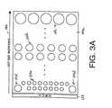
- FIG. 3Aillustrates an extraction pattern disposed on the bottom side of a light pipe in accordance with embodiments of the present invention that use a single edge-disposed light source per light pipe.
- FIG. 3Billustrates a portion of the LCD panel embodiment of FIG. 2A with oriented extraction patterns in accordance with the present invention.
- FIG. 3Cillustrates a portion of the LCD panel embodiment of FIG. 2B with oriented extraction patterns in accordance with the present invention.
- FIG. 3Dillustrates variation of the embodiment of FIG. 3C having two variable intensity light sources and a single light pipe for both.
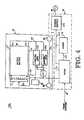
- FIG. 4is a schematic diagram of the inverter circuitry used to independently control the brightness of light sources within an LCD flat panel display within the embodiments of the present invention.
- FIG. 5illustrates the CIE chromaticity diagram including the black body curve from blue to red.
- FIG. 6is a graph illustrating the color temperatures achieved by one implementation of the dual light source and dual light pipe embodiment of the present invention for a given color temperature range.
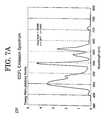
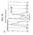
- FIG. 7A, FIG. 7 B and FIG. 7Care spectrum graphs of the energy distributions over a range of wavelengths representing the color temperature distributions of three exemplary blue light sources selected in accordance with the present invention.
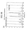
- FIG. 8 A and FIG. 8Bare spectrum graphs of the energy distributions over a range of wavelengths representing the color temperature distributions of two exemplary red light sources selected in accordances with the present invention.
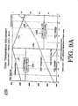
- FIG. 9Ais a graph of color temperature and luminance for one implementation of the dual light source and dual light pipe embodiment of the present invention having a blue source at 11,670 K and a red source at 3,623 K.
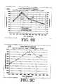
- FIG. 9Bis a graph of color temperature versus luminance for one implementation of the dual light source and dual light pipe embodiment of the present invention for a blue source at 15,599 K and a red source at 3,221 K with 2.6 mm cold cathode fluorescent tubes (CCFL).
- CCFLcold cathode fluorescent tubes
- FIG. 9Cis a graph of color temperature versus luminance for one implementation of the dual light source and dual light pipe embodiment of the present invention for a blue source at 15,599 K and a red source at 3221 K with 2.4 mm CCFL.
- FIG. 9Dis a graph of color temperature versus luminance for one implementation of the dual light source and dual light pipe embodiment of the present invention for a blue source at 15,005 K and a red source at 3,561 K with 2.6 mm CCFL.
- FIG. 10Ais a cross sectional diagram of an embodiment of the present invention having dual light pipes and four light sources, two blue sources and two red sources.
- FIG. 10Bis a cross sectional diagram of an embodiment of the present invention having a single light pipe and four light sources, two blue sources and two red sources.
- FIG. 11is a cross sectional diagram of an embodiment of the present invention having dual light pipes and three light sources, two blue sources associated with one light pipe and one red light source that is adjusted for color balancing.
- FIG. 12is a cross sectional diagram of an embodiment of the present invention having two wedge-shaped cross-nested light pipes and two light sources.
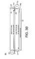
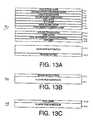
- FIG. 13Aillustrates a cross sectional diagram of another embodiment of the present invention in which backlight is recycled to increase luminance of the LCD.
- FIG. 13Billustrates a cross section of another embodiment of a rear reflector where the reflection material is applied to a plastic substrate or carrier.
- FIG. 13Cillustrates a cross section of a PTFF film reflector according to one embodiment of the present invention.
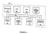
- FIG. 14illustrates an exemplary computer system in which the process of selecting approprate light sources according to one embodiment of the present invention.
- FIG. 15is a flow diagram illustrating the process of selecting appropriate light source candidates according to one selection criterion in furtherance of one embodiment of the present invention.
- FIG. 16is a flow diagram illustrating the process of selecting appropriate light source candidates according to another selection criterion in furtherance of one embodiment of the present invention.
- FIG. 17is a flow diagram illustrating a process of selecting appropriate light source candidates according to yet another selection criterion in furtherance of one embodiment of the present invention.
- FIG. 18Aillustrates a backlighting embodiment of the present invention having an array of CCF light sources.
- FIG. 18Billustrates a backlighting embodiment of the present invention having an array of CCF light sources and a scallop-shaped rear reflector.
- FIG. 18Cillustrates a backlighting embodiment of the present invention having an array of CCF light sources and a scallop-shaped rear reflector where each scallop has a light source pair.
- FIG. 1 A and FIG. 1Billustrate front and back perspective views of a display system 5 in which embodiments of the present invention can be implemented.
- exemplary display system 5utilizes a removable backlighting unit 14 that makes use of edge lighting technology
- the color temperature balancing embodiments of the present inventionare equally applicable to display systems that use fixed-in-place edge lit backlighting units and/or direct backlighting technology (FIG. 1 C and FIG. 1 D).
- the color temperature balancing embodiments of the present inventionare equally applicable to direct backlighting applications as well as edge lighting applications.
- U.S. Pat. No. 5,696,529issued Dec. 9, 1997, by Evanicky et al.
- U.S. Pat. No. 5.593,221issued Jan.
- the high resolution color flat panel display 5has a backlighting door assembly (“backlighting assembly”) 14 for direct viewing.
- This backlighting assembly 14can be removed to expose the transparent active LCD unit screen. Once removed, the transparent active LCD unit screen can be positioned on top of an overhead projector in order to project the displayed image in an enlarged fashion onto a receiving screen.
- the display system 5comprises three major assemblies.
- the base assembly 12which is coupled to a display assembly 10 via a hinge in order to allow the display assembly 10 to adjust to different angles for direct monitoring or allows the display assembly to lay flat for overhead projection configurations and for storage and transportation.
- the base assembly 12supports the display 10 for direct viewing configurations and also contains several electronic circuit systems for providing the display unit with power, audio information, and video information (see FIG. 4 ).
- the door assembly 14is also called a backlighting assembly or a liquid crystal flat panel layer.
- the display assembly 10contains two stereo speakers 8 a and 8 b as well as an active matrix LCD color screen 20 .
- an implementationutilizes an LCD screen 20 having 1280 pixels by 1024 pixels by RGB color and utilizes amorphous silicon thin film transistors (TFT).
- the LCD screen 20is composed of color TFT-LCD panel, driver ICs, control circuitry, and power supply circuitry all contained in a rigid bezel.
- LCD screen 20is capable of displaying 2 18 true colors without frame rate modulation in text or graphics mode.
- Various flat panel LCD screens and screen technologiescan be used within the scope of the present invention with proper configuration.
- the display assembly 10is back-lit via a separate assembly or removable backlighting assembly 14 .
- the dooris partially removed from the display assembly 10 .
- the backlighting assembly 14is removed so that the display 20 can become transparent for overhead projection configurations. While inserted, the backlighting assembly 14 provides backlighting for the LCD screen 20 for direct viewing configurations.
- CCFcold cathode fluorescent
- Hot cathode tubes (HCF)can also be used.
- a snap fit clip 34which is used to secure the backlighting assembly 14 to the display assembly 10 .
- FIG. 1Billustrates the back side of the display subsystem 5 with the backlighting assembly 14 completely removed to expose inner components of the display assembly 10 .
- the backlighting assembly 14removed, the back side of the LCD screen 20 is exposed.
- Located on the base assembly 12are inputs for AC power 44 and an audio/video input connector 48 .
- Power supplied to the subsystem, backlight brightness and audio volumeare controlled by the computer system's software through the audio/video input connector 48 .
- these featurescan be manually adjusted.
- also located on the display subsystem 5can be (optionally) a power on switch 2 a , a color temperature adjustment knob 2 b and a volume adjustment knob 2 c for the stereo speakers 8 a and 8 b .
- the audio/video input connector 48is coupled to the digital audio/video output of a computer system.
- Each lamp housingcan contain one or more CCF lamps 52 , depending on the particular embodiment of white balancing utilized (described further below).
- the CCF lampscan optionally be mounted within their respective lamp housing using two rubber shock mounts, as shown, 50 a and 50 b to secure lamps 52 .
- An identical configurationis employed for the top lamp housing (obscured).
- a reflective film 42is applied to the inner portions of the lamp housings and this tape extends outside, beyond the positions of the lamps 52 , for providing an optical coupling with components of the backlighting assembly 14 when inserted. The same is true for the upper lamp housing.
- FIG. 1BAlso shown in FIG. 1B are two receiving holes 32 located on the right and left sides of the display assembly 10 . These receiving holes 32 fasten to corresponding latches ( 34 not shown) located on the backlighting assembly 14 . There is also a recess associated with these latch holes 32 for removal of the backlighting assembly 14 . Also located within this region of the display assembly 10 is a magnetic reed switch 22 that is responsive to the presence of a magnet 140 (not shown) that is located along the mating edge of the backlighting assembly 14 . Using this switch 22 , the display subsystem 5 determines whether or not the backlighting assembly 14 is inserted or removed from the display assembly 10 and responds accordingly.
- the reed switch 22 and sensorin lieu of being magnetically operated, can also be implemented using and optical sensor (or switch, such as using a LED or fiber-optic device) or a mechanical sensor (or switch, such as a toggle or spring switch).
- notches 95 a and 95 blocated on the top of the display assembly 10 . These notches 95 a and 95 b are for mating with corresponding latches located on an overhead projector of the present invention for securing the display subsystem properly over an illuminating screen of the projector.
- the display subsystem 5When used in a projector configuration, the display subsystem 5 is extended so that the base assembly 12 and the display assembly 10 are flat and the facing side of the display subsystem, as shown in FIG. 1B, is placed facing down on top of the illuminating screen of the projector. In this way, light is projected through the back side of the LCD screen 20 .
- FIG. 1Cillustrates a front view of a desk top display unit (“monitor”) 36 having installed therein an LCD flat panel display assembly 38 having the color balancing system of the present invention.
- the LCD flat panel display assembly 38is fixed-in-place and edge lit with light sources along the top horizontal edge 38 a and bottom horizontal edge 38 b.
- FIG. 1Dillustrates a back perspective view of the desk top display unit 36 .
- This desk top display unit 36includes a mounting bracket 39 for mounting on a wall, a mechanical arm or for mounting with a base.
- FIG. 2Aillustrates a liquid crystal flat panel display (herein “flat panel display”) 110 a in accordance with one embodiment of the present invention.
- This flat panel display 110 acan be used within a flat panel display device having a fixed-in-place backlighting unit or can be used within a flat panel display system 5 (FIG. 1A) using a removable backlighting assembly 14 .
- the flat panel display 110 ain accordance with the present invention, provides white balance adjustment by independently varying the brightness of a pair of light sources (e.g., CCF tubes) 132 and 136 .
- a pair of light sourcese.g., CCF tubes
- a first light source 132is provided that has a wavelength spectrum with an overall color temperature less than the minimum temperature of the predetermined range; herein, a light source 132 with this characteristic is called the “red” light source for convenience.
- a second light source 136is provided that has a wavelength spectrum with an overall color temperature that is greater than the maximum temperature of the predetermined range; herein, a light source 136 with this characteristic is called the “blue” light source for convenience.
- the red light source 132is optically coupled to provide light to a first planar light pipe 130 .
- the red light source 132is positioned along an edge of the light pipe 130 .
- the blue light source 136is optically coupled to provide light to a second planar light pipe 134 .
- the blue light source 136is positioned along an edge of the light pipe 134 . Only cross sections of this planar light pipe 134 and the light source 136 are shown.
- the light sources 132 and 136are long thin tubes which are positioned on opposite sides of the planar light pipes 134 and 130 .
- the light sources 132 and 136are positioned to be substantially parallel with each other.
- the power supply for each light source 132 and 136receives a separate voltage signal for independently controlling its brightness with respect to the other light source. It is appreciated that the positions of the red tube 132 and the blue tube 136 can be switched without departing from the scope of the invention.
- an air gap 133is maintained between the two light pipes.
- This air gap 133prevents light from light source 132 being extracted within light pipe 134 and prevents light from light source 136 from being extracted within light pipe 130 .
- the air gap 133is particularly important for embodiment 110 a because each light pipe is illuminated from one edge, and the extraction dot pattern (e.g., a pattern of bumps disposed on the surface of the light pipes) corresponding to that light pipe is specifically tailored for light originating from that edge.
- the extraction dot patterne.g., a pattern of bumps disposed on the surface of the light pipes
- reflection tapes 131 and 135are reflection tapes 131 and 135 .
- a rear reflector layer 138is positioned on one side of the light pipes.
- a diffuser layer 128mylar
- BEFsbrightness enhancement layers
- DBEFdouble BEF
- the DBEF layer 124redirects light not of the proper polarization to the rear reflector layer 138 for recycling.
- the LCD panelincludes a first polarizer layer 120 followed by a back glass layer 121 followed by the selectively energized transistor layer 119 and an LCD layer 118 , followed by red/green/blue color filter layers 114 , a front glass layer 115 followed by a second polarizer layer 116 .
- a glass or acrylic protection layer 112is then used.
- the white balance or color temperature of the embodiment 110 ais maintained and adjusted using the two independently controlled light sources 132 and 136 .
- the white balanceis adjusted by altering the brightness of the light sources 132 and 136 independently.
- the phosphor mixe.g., contribution of red, green and blue phosphor
- the light pipes 130 and 134are acrylic and each contain an extraction system that uniformly and independently distributes the light from each light source across the viewing area of the display.
- the light pipes 130 and 134are mounted to address a removable backlight assembly (e.g., assembly 14 ).
- the light sourcesare located behind a diffusing system 128 to directly backlight the display rather than “edge” light the light pipe.
- the light sources 132 and 136are cold cathode fluorescent (CCF) tubes and, in another embodiment, hot cathode fluorescent (HCF) tubes are used. Constraints are placed on the amount of brightness variation tolerated during white adjustment such that the overall brightness of the display never decreases below a percentage of the maximum brightness output by the light sources 132 and 136 . In one implementation, this percentage is selected at 70 percent.
- FIG. 2Billustrates another embodiment 110 b that is analogous to embodiment 110 a except for the differences pointed out below.
- the light sources 132 and 136are long thin tubes which are positioned on the same side of the planar light pipes 134 and 130 .
- the light sources 132 and 136are positioned to be substantially parallel with each other. Because the light sources 132 and 136 are positioned on the same side of the planar light pipes 134 and 130 , the position of the reflection element 131 is shifted. It is appreciated that the positions of the red tube 132 and the blue tube 136 can be switched without departing from the scope of the invention.
- FIG. 3Aillustrates a top view of an exemplary extraction pattern 144 a that can be applied to the bottom of light pipe 130 within embodiment 110 a .
- the extraction pattern 144 ais designed to uniformly illuminate the LCD layer 118 , at any brightness, taking into consideration that the red tube 132 is positioned along one edge of the light pipe 130 .
- extraction dotsincrease in size in a proportion to their distance from the light source 132 as shown in direction 146 .
- Extraction dots 150 aare smaller since they are relatively close to the light source 132 .
- Extraction dots 150 bare slightly larger since they are relatively farther from to the light source 132 than dots 150 a .
- Extraction dots 150 care the largest because they are the farthest from light source 132 . It is appreciated that extraction pattern 144 a also includes larger sized dots 150 d at the comers near the light source 132 because the tube 132 is not as bright at the ends as in the middle sections of the tube.
- FIG. 3Billustrates a configuration 160 of light pipes and light sources (of embodiment 110 a of FIG. 2A) taking into consideration the orientation of the light extraction patterns.
- each light extraction patternis designed to operate with its own light pipe (e.g., pipe 130 ) independently of the other light pipe (e.g., pipe 134 ).
- extraction pattern 144 ais designed to uniformly distribute light to the LCD layer 118 , independently of light pipe 132 , as the brightness of light source 132 varies.
- Extraction pattern 144 bis designed to uniformly distribute light to the LCD layer 118 , independently of light pipe 130 , as the brightness of light source 136 varies.
- Light extraction pattern 144 ais shown in FIG.
- 3Bin cross section as a thin line applied to the underside of light pipe 130 .
- the dot sizesincrease within pattern 144 a from left to right because the light source 132 is positioned on the left edge of the light pipe 130 .
- the light extraction pattern 144 b applied to the underside of light pipe 134is the flipped image of pattern 144 a with the dot sizes increasing from right to left because light source 136 is positioned along the right edge of the light pipe 134 .
- each light extraction pattern 144 a and 114 bis tailored for its own light pipe
- the light pipes 130 and 134effectively operate separately and independently to uniformly distribute light over the LCD layer.
- One function of the light extraction patterns 144 a and 144 bis to uniformly distribute light over their associated light pipes even if one lamp is dimmed (or brightened) unilaterally. It is appreciated that the brightness of light source 136 is increased slightly to compensate for the fact that extraction pattern 144 a resides between the light pipe 134 and any LCD layer and thereby slightly obstructs the light emitted from light pipe 134 .
- An alternative approachadjusts the sizes of the dots of the relative dot extraction patterns to compensate for the obstruction.
- FIG. 3Cillustrates a configuration 165 of light pipes and light sources (of embodiment 110 b of FIG. 2B) taking into consideration the orientation of the light extraction patterns.
- each light extraction patternis designed to operate with their light pipe (e.g., pipe 130 ) independently of the other light pipe (e.g., pipe 134 ).
- Light extraction pattern 144 bis shown in FIG. 3C in cross section as a thin line applied to the underside of light pipe 130 . As shown, the dot sizes increase within pattern 144 b from right to left because the light source 132 is positioned on the right edge of the light pipe 130 .
- the same light extraction pattern, 144 bis also applied to the underside of light pipe 134 .
- extraction pattern 144 bis the mirror image of pattern 144 a with the dot sizes increasing from right to left because light source 136 is positioned along the right edge of the light pipe 134 .
- FIG. 3Dillustrates a variation of the embodiment 165 of FIG. 3 C.
- this embodiment 167uses both controls for the first 132 and second 136 light sources together to change the display brightness without altering the white balance setting where both the first and second light sources are positioned on the same side of a single light pipe layer 130 ′ and optically coupled to it.
- a rear reflector 138is also used.
- This embodiment 167can also be used for color temperature balancing.
- FIG. 4is a logical block diagram of electronics 170 of the display subsystem 5 .
- circuit 170includes the provision of separate inverter circuits 175 a and 175 b for separately and independently controlling light sources 132 and 136 .
- a color temperature adjustment knob 2 b(FIG. 1B) is coupled to circuit 187 which controls the voltages supplied by the inverters 175 a and 175 b to the lamps 132 and 136 over bus 180 to separately control their brightness.
- Another implementationadjusts the brightness through software control by means of a digital potentiometer.
- Inverter 175 acontrols light source 132 and inverter 175 b controls light source 136 .
- a power supply unit 184for coupling with an alternating current source 44 .
- This power supply 184supplies power via line 182 to an audio board 178 and a video board 176 .
- the audio board 178is coupled to the video board 176 via bus 186 .
- Audio and video informationare sent to the display subsystem via input interconnect 48 . It is appreciated that a variety of audio/video information transfer formats and standards can be used within the scope of the present invention, including an IBM compatible standard, a UNIX standard, or Apple Computer standard.
- Video board 176is coupled to a bus 185 for communicating and controlling elements of the display assembly 20 . It is appreciated that portions of bus 185 are composed of flex circuits so that base assembly 12 and display assembly 10 can move freely about their common hinge. Among other signals, this bus 185 carries power, control signals and audio and video data signals. The video board 176 is coupled to supply audio signals over bus 185 to stereo speakers 8 a and 8 b . Video board 176 also supplies a control signal and power over line 185 to a circuit 187 which in turn independently controls two AC to DC inverters 175 a and 175 b .
- Each invertercontains a transformer for supplying a high voltage signal, over bus 180 , to the light sources 132 and 136 and also contains a switch circuit for turning the tubes off.
- Light sources 132 and 136are separately coupled to power supply lines 180 a and 180 b , respectively, which are within bus 180 .
- Return bus 189contains a separate return lines from source 132 to inverter 175 a and from source 136 to inverter 175 b .
- Bus 185is also coupled to reed switch 22 which carries a digital signal indicating when the backlighting assembly 14 is inserted into the display assembly 10 or not present.
- Bus 185 of FIG. 4is coupled to supply video information to column driver circuits 171 .
- the column driver circuits 171control information flow to the columns of each of the rows of transistors of the LCD screen 20 to generate an image in the well-known fashion. (There are also separate row driver circuits that are not illustrated but operate in the well-known fashion.)
- FIG. 5illustrates a CIE chromaticity diagram illustrating chromaticity coordinates along the horizontal and vertical.
- the green portion 194is toward the top with yellow 192 between green 194 and red 198 .
- Blue 196is toward the left.
- a black body curve 200represents the chromaticity displayed by a tungsten filament heated to various degrees kelvin. For instance, from point D to point A along curve 200 , the curve represents the color emitted from the tungsten filament from 6,500 degrees K to 2856 degrees K. As shown, the blackbody curve 200 traverses from blue 196 to the red 198 without straying much into the yellow 192 or green 194 regions.
- the light sources 132 and 136 selected in accordance with the present inventionare those that illuminate with a color temperature that is near the blackbody curve 200 when their brightness is adjusted within a predetermined color temperature range (e.g., 5,000 to 6,500 K). That is, the color balancing system of the present invention allows adjustments to the color temperature of the flat panel display screen that remain close to the blackbody curve.
- a predetermined color temperature rangee.g., 5,000 to 6,500 K
- light sources 132 and 136 selected in accordance with the present inventionfollow the daylight color temperature locus when color temperature of the display is adjusted.
- One advantage of following the daylight color temperature locus during white balancingis that the resulting color temperature tends to be brighter (e.g. having a greater lumen value, Y), and tends to model daylight more accurately. Furthermore, the resulting color temperature tends to be more “green,” giving the display a more natural appeal.
- FIG. 6illustrates one exemplary case where the “blue” light source 136 is a CCFL tube having a color temperature of 11,670 K and the “red” light source 132 is a CCFL tube having a color temperature of 3,623 K within a flat panel display having a color balancing system 160 as shown in FIG. 3 B.
- FIG. 6illustrates that by independently varying the brightness of the light sources 132 and 136 , the resultant color temperature of the flat panel display can be altered in accordance with line 212 .
- Line 200is the same blackbody curve as shown in FIG. 5 .
- curve 212is substantially similar to curve 200 within the predetermined color temperature range of 5,000 K to 6,500 K.
- the brightnessis varied by holding one light source (e.g., 132 ) at maximum brightness and dimming the other light source (e.g., 136 ) until a minimum brightness threshold is met.
- a minimum brightness thresholdis met.
- light source 136is held constant and light source 132 is dimmed down until the minimum threshold brightness is reached.
- the light sources 132 and 136are selected such that their color temperature allows the white balancing within a predetermined range (e.g., 5,000 to 6,500) that (1) follows the blackbody curve 200 , (2) where the overall brightness of the display does not drop below a predetermined threshold over the color temperature range and (3) having a peak brightness (both light sources on) near the middle of the color temperature range.
- a predetermined rangee.g., 5,000 to 6,500
- a predetermined rangee.g., 5,000 to 6,500
- FIG. 7Aillustrates a blue light source 136 having percentages of red, green and blue phosphors such that the CCFL tube exhibits the emission spectrum 220 within the 375-775 nm wavelength range.
- the overall color temperature for the light source of FIG. 7Ais very high at 15,600 K.
- FIG. 7Billustrates a blue light source 136 having percentages of red, green and blue phosphors such that the CCFL tube exhibits the spectrum 224 within the 375-775 nm wavelength range.
- the overall color temperature for the light source of FIG. 7Bis high at 15,000 K.
- FIG. 7Cillustrates a blue light source 136 having percentages of red, green and blue phosphors such that the CCFL tube exhibits the spectrum 226 within the 375-775 nm wavelength range.
- the overall color temperature for the light source of FIG. 7Cis 10,600 K.
- FIG. 8Aillustrates a red light source 132 having percentages of red, green and blue phosphors such that the CCFL tube exhibits the spectrum 230 within the 375-775 nm wavelength range.
- the overall color temperature for the light source of FIG. 8Ais low at 3,560 K.
- FIG. 8Billustrates a red light source 132 having percentages of red, green and blue phosphors such that the CCFL tube exhibits the spectrum 232 within the 375-775 nm wavelength range.
- the overall color temperature for the light source of FIG. 8Bis low at 3,220 K.
- Ctemp @ Max Luminis the color temperature of the pair at maximum luminance.
- FIG. 9Aillustrates a color temperature and luminance diagram 240 for various brightness configurations of a color balancing embodiment 160 of FIG. 3B within the color temperature range of 5,000 to 6,500 K.
- a blue tube 136 having a color temperature of 11,670 Kis used with a red tube 132 having a color temperature of 3,623 K and corresponds to the same configuration described with respect to FIG. 6 .
- Mid point 246 c of FIG. 9Arepresents maximum luminance when both tubes are at their full brightness and a color temperature near 5,500 K is reached. This is roughly in the middle of the color temperature range 5,000 to 6,500 K.
- Region 246 arepresents the white balance adjustment where the red tube 132 is left fully on and the blue tube 136 is dimmed down in a range from 5 to 25 percent (of the original full) luminance.
- curve 242represents the luminance ratio and this value decreases (from 1.0 to 0.8) as the blue tube 136 is dimmed down.
- the color temperature as shown by curve 248decreases as the blue tube 136 is dimmed down.
- Region 246 brepresents the white balance adjustment where the blue tube 136 is left fully on and the red tube 132 is dimmed down from 5 to 25 percent of the original full luminance.
- curve 242represents the luminance ratio and this value decreases (from 1.0 to 0.8) as the red tube 132 is dimmed down. Also within region 246 b , the color temperature as shown by curve 248 increases as the red tube 132 is dimmed down.
- FIG. 9Billustrates a color temperature and luminance diagram 260 for various brightness configurations of a color balancing embodiment 160 of FIG. 3B within the color temperature range of 3,400 to 8,250 K using CCFL tubes of 2.6 mm in size.
- a blue tube 136 having a color temperature of 15,599 K(FIG. 7A) is used with a red tube 132 having a color temperature of 3,221 K (FIG. 8 B).
- Curve 262represents the luminance in Cd/sq m over the given range of color temperatures and curve 264 represents the luminance ratio (from 0 to 1.0).
- Peak luminance point 266represents the maximum brightness condition (4,600 K) when both lamps 136 and 132 are fully on.
- That portion of the curves to the right of point 266represents the condition when tube 136 is fully on and tube 132 is dimmed down to increase the color temperature. That portion of the curves to the left of point 266 represents the condition when tube 132 is fully on and tube 136 is dimmed down to decrease the color temperature.
- FIG. 9Cillustrates a color temperature and luminance diagram 270 for various brightness configurations of a color balancing embodiment 160 of FIG. 3B within the color temperature range of 3,400 to 8,250 K using CCFL tubes of 2.4 mm in size.
- a blue tube 136 having a color temperature of 15,599 K(FIG. 7A) is used with a red tube 132 having a color temperature of 3,221 K (FIG. 8 B).
- Curve 272represents the luminance in Cd/sq m over the given range of color temperatures.
- Peak luminance point 276represents the maximum brightness condition (5,000 K) when both lamps 136 and 132 are fully on.
- That portion of the curves to the right of point 276represents the condition when tube 136 is fully on and tube 132 is dimmed down to increase the color temperature. That portion of the curves to the left of point 276 represents the condition when tube 132 is fully on and tube 136 is dimmed down to decrease the color temperature.
- FIG. 9Dillustrates a color temperature and luminance diagram 280 for various brightness configurations of a color balancing embodiment 160 of FIG. 3B within the color temperature range of 3,400 to 8,250 K using CCFL tubes of 2.6 mm in size.
- a blue tube 136 having a color temperature of 15,599 K(FIG. 7A) is used with a red tube 132 having a color temperature of 3,221 K (FIG. 8 B).
- Curve 282represents the luminance in Cd/sq m over the given range of color temperatures.
- Peak luminance point 286represents the maximum brightness condition (4,800 K) when both lamps 136 and 132 are fully on.
- That portion of the curves to the right of point 286represents the condition when tube 136 is fully on and tube 132 is dimmed down to increase the color temperature. That portion of the curves to the left of point 286 represents the condition when tube 132 is fully on and tube 136 is dimmed down to decrease the color temperature.
- the red and/or blue light sources 132 and 136 selectedcan be slightly blue shifted.
- FIG. 10Aillustrates a cross section of an alternate embodiment 310 of a color balancing system in accordance with the present invention that utilizes four light sources.
- Two red light sources 312 and 314are positioned on opposite sides of a planar light pipe 130 and are parallel with each other. The brightness of these two red light sources 312 and 314 are varied in tandem.
- Two blue light sources 316 and 318are positioned on opposite sides of a planar light pipe 134 and are parallel with each other. The brightness of these two blue light sources 316 and 318 are varied in tandem independently of the red light sources 312 and 314 . It is appreciated that the positions of the blue and red light sources can be switched in accordance with the present invention.
- Light pipe 134is positioned under light pipe 130 .
- An air gap 133is positioned between the light pipes 130 and 134 but is optional in this embodiment because the locations of the red and blue light source pairs are symmetrical with respect to both light pipes 130 and 134 .
- CCFL tubes or HCL tubescan be used as the light sources with particular red, green, blue phosphor contributions to differentiate the blue from the red light sources.
- the extraction pattern 144 c applied to the underside of each light pipe 130 and 134utilizes extraction dots that vary in size with respect to their closest distance from the two light sources. That, is, along the sides having the light sources, the extraction dots are smaller and they increase in size (from both sides) toward the middle.
- An extraction pattern 144 c fitting this descriptionis described in U.S. Pat. No. 5,696,529, issued Dec. 9, 1997 by Evanicky, et al., and assigned to the assignee of the present invention.
- the voltage driving the red light sources 312 and 314is varied to vary their brightness.
- the color temperaturecan be increased from mid-range by dimming down the red light sources 312 and 314 in tandem.
- the voltage of the inverter supply driving the blue light sources 316 and 318is varied to vary their brightness.
- the color temperaturecan be decreased from mid-range by dimming down the blue light sources 316 and 318 in tandem.
- Embodiment 310provides increased brightness through the color temperature variation because more light sources are utilized. Therefore, this embodiment 310 has a larger pool of red/blue light source candidates which allow good color temperature range variation while also providing adequate brightness through the color temperature range. However, since more light sources are used in embodiment 310 over the dual light pipe embodiment 160 , embodiment 310 consumes more power.
- FIG. 10Billustrates a cross section of an embodiment 330 of a color balancing system in accordance with the present invention that is a variation of embodiment 310 .
- Embodiment 330includes a single planar light pipe 340 having a red/blue pair of light sources located on two opposite sides. On the left are located a red light source 312 and a blue light source 316 and on the right are located a red light source 314 and a blue light source 318 . Like embodiment 310 , the red light sources 312 and 314 of embodiment 330 are varied in tandem and the blue light sources 316 and 318 are varied in tandem, independently from the red light sources 312 and 214 .
- An extraction pattern 144 cis applied to the underside of light pipe 340 .
- Color temperature variationis performed for embodiment 330 in the same manner as described with respect to embodiment 310 .
- the advantage of embodiment 330is that a single light pipe 340 can be used. Since the brightness of the red and blue light sources are varied in tandem (for a given color), only two inverters 175 a and 175 b (FIG. 4) are required for embodiment 310 and for embodiment 330 .
- the voltage signal on line 180 a of FIG. 4can be coupled to control both red light sources 312 and 314 and the voltage signal on line 180 b can be coupled to control both blue light sources 316 and 318 .
- FIG. 11illustrates a cross section of another embodiment 350 of a color balancing system in accordance with the present invention that utilizes two blue light sources 316 and 318 and a single red light source 314 .
- the blue light sources 316 and 318are positioned along opposite edges of a first light pipe 130 .
- An extraction pattern 144 cis applied to the underside of light pipe 130 .
- a single red light source 314is positioned along one edge of light pipe 134 (e.g., on the right or left side). When light source 314 is positioned on the right side, as shown, extraction pattern 144 b is used with light pipe 134 and when light source 314 is positioned on the left side, extraction pattern 144 a is used.
- the blue light sources 316 and 318are maintained at (or slightly above) a color temperature above a predetermined color temperature range (e.g., at or above 6,500 K).
- the blue light sources 316 and 318are maintained at or near their full brightness to provide the required luminance for the display and the red light source 314 is adjusted in brightness to provide a varying degree of down-shifted color temperature.
- Embodiment 350provides the advantage that the color temperature of the display can effectively be adjusted without affecting the backlight luminance. That is to say, if the emission spectra of the red lamp is in the deep red region (e.g., 658 nm), then even at its full brightness it would only contribute about 5 percent of the backlight luminance because of the human eye's insensitivity to that color region. It is appreciated that two inverters 175 a and 175 b are required for embodiment 350 even though the brightness of light sources 316 and 318 is held constant. Power consumption for the red light source 314 is within the region of 0.5 watt.
- FIG. 12illustrates a cross section of an embodiment 370 of a color balancing system in accordance with the present invention.
- Embodiment 370is similar to embodiment 160 except the planar light tubes 372 and 374 are wedge-shaped in cross section.
- the light tubes 372 and 374are positioned as shown in FIG. 12 so that they have a lower profile in cross section. That is, the light pipes 130 and 134 of embodiment 160 , in one implementation, are roughly 3 mm thick so their total width is just over 6 mm when stacked with an air gap 133 in between.
- the wedge-shaped light pipes 372 and 374can be positioned as shown in FIG.
- the overall height of light pipes 372 and 374is only 3 mm since they are inter-crossed (e.g., cross-nested) together.
- a modification of extraction pattern 144 ais applied to the underside of light pipe 372 and a modification of extraction pattern 144 b is applied to the underside of light pipe 374 .
- a modification of the extraction patternis necessary to compensate for the influence on extraction resulting from the angle of the wedge of each light pipe 372 374 .
- the usercan adjust the color balance of the display in accordance with the present invention.
- the usercan adjust a slider between two extreme mechanical positions in which the position of the slider (or knob 2 b ) represents a particular color temperature within the predetermined color temperature range.
- the particular color temperature selectedis then translated into a dimming configuration by which one or more tubes are dimmed to achieve the color temperature.
- the slideris provided but the display also contains a chromaticity measuring device (e.g., a calorimeter) with gives the user immediate feedback as to the color temperature of the display. The user then monitors the measuring device while adjusting the slider mechanism until the desired color temperature is reached.
- a chromaticity measuring devicee.g., a calorimeter
- the white balancecan be set via a feedback loop from a colorimeter positioned so that it analyzes the color temperature of the display and feeds that information to the host computer through a serial port and the host computer then automatically adjusts the white balance.
- FIG. 13Aillustrates on embodiment of the present invention in which backlight is recycled to increase luminance of the LCD.
- a flat panel LCD 410including a backlight distributor 430 , which may comprise various configurations of light pipes and light sources, such as the embodiments of the dual light pipes illustrated in FIGS. 2A-2B and FIGS. 3B-3C.
- flat panel LCD 410further includes a rear reflector layer 438 positioned on the back side of the backlight distributor 430 for recycling light.
- a diffuser layer 428is followed by one or more brightness enhancement layers (BEFS) 426 , followed by a dual brightness enhancement film (DBEF) layer 424 which is followed by a special cover layer 422 .
- BEFSbrightness enhancement layers
- DBEFdual brightness enhancement film
- the LCD panelincludes a first (rear) polarizer layer 120 followed by a selectively energized transistor-layer 110 and a LCD layer 118 , followed by red/green/blue color filter layers 114 , a front glass layer 115 followed by a second polarizer layer 116 .
- a glass or acrylic protection layer 112is then used.
- DBEF layer 424 of FIG. 13Ain combination with the rear reflector 438 , increases brightness of flat panel LCD 410 by first “pre-polarizing” the light emitted from the backlight distributor 430 to the same orientation as the rear polarizer 120 . Any light having the wrong orientation is reflected by DBEF layer 424 to the rear reflector 438 where much of it is rephased and reflected back to the display or lost through absorption. A large portion of the rephased and reflected light from the reflector 438 can then pass through the rear polarizer layer 120 .
- rear reflector 438the amount of light that can be recycled depends upon the reflectivity of rear reflector 438 .
- Conventional reflective materials currently employed by the industryonly reflect about 92% of the light.
- a white rear reflector 438made of a Teflon-like material developed by W.I. Gore and Associates, Inc., and sold under the name of PTFF, is used.
- PTFFTeflon-like material developed by W.I. Gore and Associates, Inc.
- PTFFTeflon-like material developed by W.I. Gore and Associates, Inc.
- PTFFTin-like material
- rear reflector 438comprises a layer of PTFF 437 coated onto plastic film substrate 441 , and is illustrated in FIG. 13 C. It should be apparent to those ordinarily skilled in the art, upon reading the present disclosure, that other materials displaying similar light-rephasing and reflectivity properties may also be used.
- LCD brightnessmay be further enhanced by the using a brightness enhancement film (BEF) in between the backlight distributor 430 and the DBEF layer 424 .
- BEFbrightness enhancement film
- flat panel LCD 410includes optional BEF layer(s) 426 .
- BEFbrightness enhancement film
- LCD brightnessmay be increased by 50%.
- An even higher luminance gainmay be attained when two layers of BEF are aligned at an angle of 90 to each other, a forming a “crossed BEF” layer.
- a luminance gain of 75%may be attained when crossed BEFs are used.
- An additional benefit of the crossed BEFis that the viewing angle of the LCD is significantly increased.
- a special cover sheet 422may be used to eliminate such off-axis visual artifacts.
- special cover sheet 422comprises a thin light diffusing film placed between the DBEF and the rear polarizer of the LCD such that a small portion of the backlight is scattered at large off-axis angles.
- special cover sheet 422should not cause significant de-polarization because excess de-polarization would reduce the efficiency of the light-recycling process.
- special cover sheet 422is made of an Lexan 8 A 35 material available from General Electric. Further, in the present embodiment, the special cover sheet 422 is cut with its optical axis matching the transmission axis of the polarizer and the DBEF.
- FIG. 13Billustrates another embodiment of a rear reflector 440 that may be used in place of rear reflector 438 of FIG. 13 A.
- rear reflector 440comprises a layer of barium sulfate 439 deposited on substrate 441 such as white plastic film(s).
- barium sulfate layer 439may be deposited on substrate 441 by first mixing barium sulfate powder with an organic binder to form a paste, and then screen printing the paste on the substrate 441 .
- barium sulfate layer 439should be at least 0.01′′ thick. It should be apparent to those of ordinary skill in the art, upon reading the present disclosure, that numerous well known organic binders and coating techniques may also be used to manufacture rear reflector 440 .
- FIG. 14illustrates an exemplary computer system 500 upon which one embodiment of the present invention may be practiced. It is appreciated that system 500 of FIG. 14 is exemplary only and that the present invention can operate within a number of different computer systems and/or electronic device platforms.
- System 500 of FIG. 14includes an address/data-bus 510 for communicating information and a central processor unit 520 coupled to bus 510 for processing information and instructions.
- System 500also includes data storage features such as computer-usable volatile memory 530 , e.g. random access memory (RAM), coupled to bus 510 for storing information and instructions for central processor unit 520 ; computer usable non-volatile memory 540 , e.g. read only memory (ROM), coupled to bus 510 for storing static information and instructions for the central processor unit 520 ; a data storage unit 550 (e.g., a magnetic or optical disk and disk drive) coupled to bus 510 for storing information and instructions; and a network interface unit 590 (e.g.
- RAMrandom access memory
- ROMread only memory
- System 500also includes optional devices such as an optional alphanumeric input device 570 coupled to bus 510 for communicating information and command selections to central processor unit 520 ; an optional cursor control device 580 coupled to bus 510 for communicating user input information and command selections to central processor unit 520 ; and an optional display device 560 coupled to bus 510 for displaying information.
- optional devicessuch as an optional alphanumeric input device 570 coupled to bus 510 for communicating information and command selections to central processor unit 520 ; an optional cursor control device 580 coupled to bus 510 for communicating user input information and command selections to central processor unit 520 ; and an optional display device 560 coupled to bus 510 for displaying information.
- LCD color temperatureis altered by selectively dimming the brightness of one or the other of the light sources so that their overall contribution matches the desired LCD color temperature.
- LCD color temperatureis also dependent upon the percentages of different phosphors that are used within the CCFLs. For instance, a CCFL tube that includes 33% of R-phosphor, 33% of G-phosphor, and 33% of B-phosphor will have different color temperature, chromaticity, and brightness than another one that includes 40% R-phosphor, 40% G-phosphor, and 20% B-phosphor. Therefore, it is necessary to select an appropriate percentage composition of R, G, and B phosphors such that the color temperature, luminance, and chromaticity of the LCD may be accurately controlled.
- an appropriate percentage composition of phosphorsis selected such that, within a predetermined range of color temperature, the brightness of the LCD is not reduced below a given threshold minimum (e.g., 70 percent of the maximum brightness).
- the appropriate mix of R, G, B phosphorsis selected such that, within the predetermined color temperature range, the color temperature of the display is held close to the black body curve 200 of the CIE chromaticity diagram 190 (FIG. 5 ).
- the appropriate mix of R, G, B phosphors in the light sourcesis selected such that their maximum brightness point is set to be near the middle of the predetermined color temperature range.
- FIG. 15is a flow diagram 600 illustrating a process (executed on system 500 ) of selecting appropriate light source candidates such that, within a predetermined range of color temperature, the brightness of the LCD is not reduced below a given threshold minimum (e.g., 70 percent of the maximum brightness).
- a threshold minimume.g. 70 percent of the maximum brightness.
- the selectionis made for a “blue” light source 136 , and a “red” light source 132 of a color balancing embodiment 160 of FIG. 3 B.
- a target color temperature rangeis predetermined to be between 3,400 K to 8,250 K.
- high-resolution (1 nm) spectral files for particular types of R, G, and B phosphorsare input into computer system 500 and stored at RAM 530 or data storage unit 550 .
- the high-resolution spectral files for R, G, and B phosphorsmay be obtained from manufacturers of the phosphors.
- each spectral filecontains energy data of the emission spectrum of one type of phosphor (e.g. R-phosphors, G-phosphors or B-phosphors). Then, the energy data of the emission spectra of the R, G, and B phosphors are converted to luminance (brightness) data using the human eye sensitivity data over the visible emission spectrum.
- each light source candidateis essentially represented by the percentages of R-phosphors, G-phosphors, and B-phosphors present in the light source candidate.
- a pool of light source candidatesare generated by varying the amount of different phosphor types.
- a 5%-increment scheme in the relative amounts of different phosphor typesis adopted.
- one light source candidatemay have a percentage composition of 25% R-phosphors, 35% G-phosphors, and 40% B-phosphors.
- Another light source candidatemay have a percentage composition of 40% R-phosphors, 40% G-phosphors, and 20% B-phosphors.
- 400 (20 ⁇ 20) light source candidatesare available.
- the luminance spectrum W( ⁇ ) of each of the light source candidatesis computed.
- a “bluish.” luminance spectrum W 1 ( ⁇ ) for “blue” light source 136is calculated according to the following equation:
- a light source candidateis matched up with another light source candidate to form a candidate pair.
- the total number of light source candidateis 20 for each of the two light sources 132 and 136 . Therefore, a total number of possible candidate pairs is 400.
- a combined luminance spectrum, W 3 ( ⁇ ),is computed for the selected candidate pair.
- the combined luminance spectrumresults from contributions from “blue” light source candidate and from “red” light source candidate, and can be calculated according to the equation:
- W 3 ( ⁇ )L 1 * W 1 ( ⁇ )+ L 2 * W 2 ( ⁇ ),
- L 1 and L 2represent brightness levels of “blue” light source 136 , and “red” light source 132 , respectively.
- the brightness level Li of the “blue” light source 136 , and the brightness level L 2 of the “red” light source 132may be selectively and independently adjusted to modify the color temperature of the LCD. Further, according to the present embodiment, a 5% increment/decrement scheme in the intensity levels L 1 and L 2 is adopted. Thus, in the present embodiment, after discarding redundancy, a total number of 200 combined luminance spectrums are calculated for the selected candidate pair.
- a luminance value and a color temperatureis calculated.
- Methods for calculating luminance values and color temperatures from luminance spectrumsare well known in the art. Therefore, details of such methods are not described herein to avoid obscuring aspects of the present invention.
- a table for storing the luminance values and color temperatures associated with the selected candidate pairis constructed, thus forming a color temperature-luminance relationship for the selected candidate pair.
- candidate pairs having luminance values (L) smaller than a minimum luminance threshold (e.g. 70% of Lmax) between the predetermined color temperature range (e.g. between 3,400 K to 8,250 K)are rejected. In this way, a significant number of candidate pairs are rejected and the simulation time for any subsequent steps is reduced.
- a minimum luminance thresholde.g. 70% of Lmax
- step 690it is determined whether all the possible combinations of candidate light sources have been processed. If it is determined that all possible combinations of the candidate light sources have been processed, candidate pairs that do not meet the requisite criterion are rejected, and the processed ends. However, if there are possible combinations of candidate light sources that have not been processed, steps 610 through 690 are repeated.
- FIG. 16is a flow diagram 700 illustrating a process of selecting appropriate light source candidates such that within the predetermined color temperature range, the color temperature is held close to the black body curve 200 of the CIE chromaticity diagram 190 .
- a candidate pairis selected from the pool of candidate pairs that have not been rejected. According to the one embodiment, the process illustrated in flow diagram 700 is performed after candidate pairs that do not meet the luminance requirement are rejected.
- the chromaticity values (x, y) for a candidate pairis determined from the combined luminance spectrums calculated in step 660 .
- a different chromaticity value (x, y)is calculated for each luminance spectrum for each candidate pair.
- the chromaticity values over the luminance spectrums for a candidate pairare compared to the black body curve 200 of chromaticity diagram 190 .
- a relationship of color temperature and chromaticityis built, and the relationship is compared to the black body radiation curve.
- Methods for performing statistical comparison for two set of dataare well known in the art. Therefore, it would be apparent to those of ordinary skill in the art, upon reading the present disclosure, that numerous statistical analysis algorithms may be implemented herein.
- the sum of the derivativesare computed and compared to other sums of other candidate pairs.
- step 740if it is determined that the chromaticity values of the candidate pair is significantly deviated from the black body curve 200 , then the candidate pair is rejected.
- step 750if it is determined that the chromaticity does not significantly deviate from the black body curve 200 , then the candidate pair remains in the pool.
- a new candidate pairis selected from the remaining pool of candidate pairs, and steps 710 - 750 are repeated until all the candidate pairs have been processed. Thereafter, at step 770 , when all candidate pairs have been processed, the process returns, and the number of candidate pairs is further reduced.
- FIG. 17is a flow diagram 800 illustrating a process of selecting appropriate light source candidates such that a maximum luminance occurs approximately in the middle of a given color temperature range.
- a pair of light source candidatesare selected from the pool of candidate pairs that have passed the luminance threshold requirement and that closely follow the black body curve 200 .
- color temperature values of the selected candidate pairare plotted against luminance values of the selected candidate pair to provide a color temperature and luminance diagram. Exemplary color temperature and luminance diagrams are illustrated in FIGS. 9B and 9C.
- step 830it is determined whether a peak luminance point, or maximum luminance point, i.e. when both “blue” and “red” light source candidates are turned on at a maximum intensity, occurs approximately at the middle of the given color temperature range.
- peak luminance point 266occurs at roughly 4700 K.
- peak luminance point 276occurs at roughly 5050 K.
- the candidate pairis rejected. For instance, in the example as illustrated in FIG. 9B, for a predetermined range of color temperature between 3,400 K to 8,250 K, the peak luminance point should occur at approximately 5825 K. The peak luminance point, however, occurs at approximately 4700 K for the example as illustrate in FIG. 9 B. Therefore, the example as illustrated in FIG. 9B does not satisfy this requirement, and will be rejected.
- step 850if it is determined that the maximum luminance occurs roughly in the middle of the predetermined color temperature range, then the candidate pair remains in the pool of potential candidates. Thereafter, the process returns.
- a new candidate pairis selected from the remaining pool of candidate pairs, and steps 810 - 850 are repeated until all the candidate pairs have been processed. Thereafter, at step 870 , when all candidate pairs have been processed, the process returns, and the number of candidate pairs is further reduced.
- an offset valuemay be added to the luminance spectrum so as to compensate for the yellow shift caused by many of the layers, e.g., the acrylic in the light pipes, the ultra-violet cured extraction patterns, the DBEF and BEF films, the polarizers, the LCD layer and the color filters, within an LCD flat panel display system.
- the offset valueis largely determined by the experience and skill of the light tube designer, and by empirical experimentation.
- light tube designersmay adjust the values of the percentage compositions of the R-phosphors, G-phosphors, and B-phosphors to produce a pair of CCFL tubes that have the ideal “look and feel.”
- FIG. 18Aillustrates a backlighting embodiment 910 of the present invention that positions an array of light sources 132 a - 132 b and 136 a - 136 b directly under the display layer 912 thereby obviating the need for any light pipes.
- a diffuser layer 914is used to diffuse the light emitted from the light sources to promote light uniformity. If the light sources are placed near the diffuser layer 914 (e.g., less than one inch away), then hiding lines may be required. These hiding lines are typically etched on the diffuser layer and are more numerous near the body of the light sources. The relative intensities of the light sources (red and blue) can be controlled to perform color temperature balancing as described above in the numerous edge lit embodiments.
- a rear reflector layer 138is also used in embodiment 910 .
- the information display layer 912(“display layer 912 ”) is generally a non-emissive modulated display layer.
- the layer 912is non-emissive meaning that it does not generate any original light but rather modules the light of another light source (e.g., sources 132 a-b and 136 a-b ).
- the display layer 912modules light that layer 912 does not generate. Modulation is used to form images on layer 912 thereby conveying information.
- display layer 912is a liquid crystal display layer of the technology shown in FIG. 2A including the layers between layer 126 and layer 112 .
- the display layer 912an electrophoretic display layer using ion migration for modulation.
- Layer 912can also be a reflective display layer or a layer having a fixed modulated design printed or otherwise laid thereon.
- Layer 912can also be an electromechanical display using shuttered pixels (“windows”) for modulation.
- Layer 912can also be a ferroelectric display.
- FIG. 18Billustrates another backlighting embodiment 922 similar to embodiment 910 except the rear reflector 920 contains scallops cut therein and each light source 132 a - 132 b and 136 a - 136 b is positioned with its own scallop to increase directed reflection.
- FIG. 18Cillustrates another backlighting embodiment 930 that is similar to embodiment 922 except that within the reflector layer 936 a pair of light sources 132 a and 136 can be positioned within a single scallop.
Landscapes
- Physics & Mathematics (AREA)
- Nonlinear Science (AREA)
- General Physics & Mathematics (AREA)
- Optics & Photonics (AREA)
- Mathematical Physics (AREA)
- Chemical & Material Sciences (AREA)
- Crystallography & Structural Chemistry (AREA)
- Liquid Crystal (AREA)
- Liquid Crystal Display Device Control (AREA)
Abstract
Description
| TABLE I | |||||
| Pair | Red Tube | Blue Tube | Ctemp @ | ||
| 1 | 3,560 | 15,600 | 5,893 | ||
| 2 | 3,220 | 15,600 | 5,635 | ||
| 3 | 3,560 | 10,600 | 5,468 | ||
| 4 | 3,560 | 15,000 | 5,635 | ||
| 5 | 3,220 | 15,000 | 5,367 | ||
| Where Ctemp @ Max Lumin is the color temperature of the pair at maximum luminance. | |||||
Claims (25)
Priority Applications (1)
| Application Number | Priority Date | Filing Date | Title |
|---|---|---|---|
| US09/811,988US6657607B1 (en) | 1998-05-29 | 2001-03-19 | Liquid crystal flat panel display with enhanced backlight brightness and specially selected light sources |
Applications Claiming Priority (2)
| Application Number | Priority Date | Filing Date | Title |
|---|---|---|---|
| US09/087,280US6243068B1 (en) | 1998-05-29 | 1998-05-29 | Liquid crystal flat panel display with enhanced backlight brightness and specially selected light sources |
| US09/811,988US6657607B1 (en) | 1998-05-29 | 2001-03-19 | Liquid crystal flat panel display with enhanced backlight brightness and specially selected light sources |
Related Parent Applications (1)
| Application Number | Title | Priority Date | Filing Date |
|---|---|---|---|
| US09/087,280ContinuationUS6243068B1 (en) | 1998-05-29 | 1998-05-29 | Liquid crystal flat panel display with enhanced backlight brightness and specially selected light sources |
Publications (1)
| Publication Number | Publication Date |
|---|---|
| US6657607B1true US6657607B1 (en) | 2003-12-02 |
Family
ID=22204232
Family Applications (3)
| Application Number | Title | Priority Date | Filing Date |
|---|---|---|---|
| US09/087,280Expired - LifetimeUS6243068B1 (en) | 1998-05-29 | 1998-05-29 | Liquid crystal flat panel display with enhanced backlight brightness and specially selected light sources |
| US09/590,753Expired - LifetimeUS6448955B1 (en) | 1998-05-29 | 2000-06-08 | Liquid crystal flat panel display with enhanced backlight brightness and specially selected light sources |
| US09/811,988Expired - LifetimeUS6657607B1 (en) | 1998-05-29 | 2001-03-19 | Liquid crystal flat panel display with enhanced backlight brightness and specially selected light sources |
Family Applications Before (2)
| Application Number | Title | Priority Date | Filing Date |
|---|---|---|---|
| US09/087,280Expired - LifetimeUS6243068B1 (en) | 1998-05-29 | 1998-05-29 | Liquid crystal flat panel display with enhanced backlight brightness and specially selected light sources |
| US09/590,753Expired - LifetimeUS6448955B1 (en) | 1998-05-29 | 2000-06-08 | Liquid crystal flat panel display with enhanced backlight brightness and specially selected light sources |
Country Status (2)
| Country | Link |
|---|---|
| US (3) | US6243068B1 (en) |
| WO (1) | WO1999063397A1 (en) |
Cited By (69)
| Publication number | Priority date | Publication date | Assignee | Title |
|---|---|---|---|---|
| US20020018053A1 (en)* | 2000-05-02 | 2002-02-14 | Tadao Kyomoto | Light modulation information display device and illumination control device |
| US20030020955A1 (en)* | 2001-07-30 | 2003-01-30 | Hitchin Trevor D. | Customized form output apparatus and method |
| US20030085867A1 (en)* | 2001-11-06 | 2003-05-08 | Michael Grabert | Apparatus for image projection |
| US20040095558A1 (en)* | 2001-02-27 | 2004-05-20 | Lorne Whitehead | High dynamic range display devices |
| US20040125853A1 (en)* | 2002-12-26 | 2004-07-01 | Ming-Feng Yu | Ambient temperature control apparatus used for measuring display panel |
| US20040239849A1 (en)* | 2003-06-02 | 2004-12-02 | Wang Po Hsien | Liquid crystal display with mirror face function |
| US20050104027A1 (en)* | 2003-10-17 | 2005-05-19 | Lazarev Pavel I. | Three-dimensional integrated circuit with integrated heat sinks |
| US20050162737A1 (en)* | 2002-03-13 | 2005-07-28 | Whitehead Lorne A. | High dynamic range display devices |
| US6954191B1 (en)* | 1999-11-12 | 2005-10-11 | Koninklijke Philips Electronics N.V. | Liquid crystal display device |
| US20060007101A1 (en)* | 2004-05-31 | 2006-01-12 | Lg Philips Lcd Co., Ltd. | Liquid crystal display |
| US20060082701A1 (en)* | 2004-10-18 | 2006-04-20 | Tong Li | Module for liquid crystal displays |
| EP1657936A1 (en)* | 2004-11-10 | 2006-05-17 | Sony Ericsson Mobile Communications AB | White balance adjustment |
| US7064740B2 (en) | 2001-11-09 | 2006-06-20 | Sharp Laboratories Of America, Inc. | Backlit display with improved dynamic range |
| US7164284B2 (en) | 2003-12-18 | 2007-01-16 | Sharp Laboratories Of America, Inc. | Dynamic gamma for a liquid crystal display |
| US7342592B2 (en) | 2004-06-14 | 2008-03-11 | Sharp Laboratories Of America, Inc. | System for reducing crosstalk |
| US20080062115A1 (en)* | 2006-09-13 | 2008-03-13 | Houston Brown | System and method for predicting a failure of a backlight for an LCD display |
| US20080218471A1 (en)* | 2003-10-07 | 2008-09-11 | Jerry Chung | Electrophoretic display with thermal control |
| CN100442113C (en)* | 2005-02-23 | 2008-12-10 | 矽感成像有限公司 | Single color LCD able to display multicolor |
| US7505018B2 (en) | 2004-05-04 | 2009-03-17 | Sharp Laboratories Of America, Inc. | Liquid crystal display with reduced black level insertion |
| US7525528B2 (en) | 2004-11-16 | 2009-04-28 | Sharp Laboratories Of America, Inc. | Technique that preserves specular highlights |
| US7532192B2 (en) | 2004-05-04 | 2009-05-12 | Sharp Laboratories Of America, Inc. | Liquid crystal display with filtered black point |
| US7556836B2 (en) | 2004-09-03 | 2009-07-07 | Solae, Llc | High protein snack product |
| US7602369B2 (en) | 2004-05-04 | 2009-10-13 | Sharp Laboratories Of America, Inc. | Liquid crystal display with colored backlight |
| US7612757B2 (en) | 2004-05-04 | 2009-11-03 | Sharp Laboratories Of America, Inc. | Liquid crystal display with modulated black point |
| US7623105B2 (en) | 2003-11-21 | 2009-11-24 | Sharp Laboratories Of America, Inc. | Liquid crystal display with adaptive color |
| US20100002026A1 (en)* | 2007-02-01 | 2010-01-07 | Dolby Laboratories Licensing Corporation | Calibration of displays having spatially-variable backlight |
| US7777714B2 (en) | 2004-05-04 | 2010-08-17 | Sharp Laboratories Of America, Inc. | Liquid crystal display with adaptive width |
| CN101404776B (en)* | 2007-08-14 | 2010-12-01 | 三星电机株式会社 | Auto White Balance Method |
| US7853094B2 (en) | 2006-01-24 | 2010-12-14 | Sharp Laboratories Of America, Inc. | Color enhancement technique using skin color detection |
| US7872631B2 (en) | 2004-05-04 | 2011-01-18 | Sharp Laboratories Of America, Inc. | Liquid crystal display with temporal black point |
| US20110045172A1 (en)* | 1994-05-05 | 2011-02-24 | Donnelly Corporation | Method of forming a mirrored bent cut glass shape for vehicular exterior rearview mirror assembly |
| US7898519B2 (en) | 2005-02-17 | 2011-03-01 | Sharp Laboratories Of America, Inc. | Method for overdriving a backlit display |
| US20110084198A1 (en)* | 2002-09-20 | 2011-04-14 | Donnelly Corporation | Interior rearview mirror information display system for a vehicle |
| US20110096387A1 (en)* | 2002-09-20 | 2011-04-28 | Donnelly Corporation | Reflective mirror assembly |
| US20110128137A1 (en)* | 1994-05-05 | 2011-06-02 | Donnelly Corporation | Vehicular blind spot indicator mirror |
| US20110134553A1 (en)* | 1998-01-07 | 2011-06-09 | Donnelly Corporation | Interior rearview mirror system with forwardly-viewing camera |
| US20110147570A1 (en)* | 2002-05-03 | 2011-06-23 | Donnelly Corporation | Vehicle rearview mirror system |
| US20110166779A1 (en)* | 1999-11-24 | 2011-07-07 | Donnelly Corporation | Interior rearview mirror system |
| US20110164135A1 (en)* | 1998-01-07 | 2011-07-07 | Donnelly Corporation | Interior rearview mirror system |
| US20110169956A1 (en)* | 1997-08-25 | 2011-07-14 | Donnelly Corporation | Interior rearview mirror system for a vehicle |
| US8019505B2 (en) | 2003-10-14 | 2011-09-13 | Donnelly Corporation | Vehicle information display |
| US8044776B2 (en) | 2000-03-02 | 2011-10-25 | Donnelly Corporation | Rear vision system for vehicle |
| US8047667B2 (en) | 2002-06-06 | 2011-11-01 | Donnelly Corporation | Vehicular interior rearview mirror system |
| US8050511B2 (en) | 2004-11-16 | 2011-11-01 | Sharp Laboratories Of America, Inc. | High dynamic range images from low dynamic range images |
| US8050512B2 (en) | 2004-11-16 | 2011-11-01 | Sharp Laboratories Of America, Inc. | High dynamic range images from low dynamic range images |
| US8063753B2 (en) | 1997-08-25 | 2011-11-22 | Donnelly Corporation | Interior rearview mirror system |
| US8072318B2 (en) | 2001-01-23 | 2011-12-06 | Donnelly Corporation | Video mirror system for vehicle |
| US8083386B2 (en) | 2001-01-23 | 2011-12-27 | Donnelly Corporation | Interior rearview mirror assembly with display device |
| US8095310B2 (en) | 2000-03-02 | 2012-01-10 | Donnelly Corporation | Video mirror system for a vehicle |
| US8121401B2 (en) | 2006-01-24 | 2012-02-21 | Sharp Labortories of America, Inc. | Method for reducing enhancement of artifacts and noise in image color enhancement |
| US8154418B2 (en) | 2008-03-31 | 2012-04-10 | Magna Mirrors Of America, Inc. | Interior rearview mirror system |
| US8162493B2 (en) | 1999-11-24 | 2012-04-24 | Donnelly Corporation | Interior rearview mirror assembly for vehicle |
| US8179586B2 (en) | 2003-10-02 | 2012-05-15 | Donnelly Corporation | Rearview mirror assembly for vehicle |
| US8179236B2 (en) | 2000-03-02 | 2012-05-15 | Donnelly Corporation | Video mirror system suitable for use in a vehicle |
| US8194133B2 (en) | 2000-03-02 | 2012-06-05 | Donnelly Corporation | Vehicular video mirror system |
| US20120154627A1 (en)* | 2010-12-20 | 2012-06-21 | William Rivard | Systems and methods for controlling color balance for a photographic illuminator |
| US8277059B2 (en) | 2002-09-20 | 2012-10-02 | Donnelly Corporation | Vehicular electrochromic interior rearview mirror assembly |
| US8282226B2 (en) | 2002-06-06 | 2012-10-09 | Donnelly Corporation | Interior rearview mirror system |
| US8288711B2 (en) | 1998-01-07 | 2012-10-16 | Donnelly Corporation | Interior rearview mirror system with forwardly-viewing camera and a control |
| US8294975B2 (en) | 1997-08-25 | 2012-10-23 | Donnelly Corporation | Automotive rearview mirror assembly |
| US8325055B2 (en) | 2003-05-19 | 2012-12-04 | Donnelly Corporation | Mirror assembly for vehicle |
| US8395577B2 (en) | 2004-05-04 | 2013-03-12 | Sharp Laboratories Of America, Inc. | Liquid crystal display with illumination control |
| US8462204B2 (en) | 1995-05-22 | 2013-06-11 | Donnelly Corporation | Vehicular vision system |
| US8482698B2 (en) | 2008-06-25 | 2013-07-09 | Dolby Laboratories Licensing Corporation | High dynamic range display using LED backlighting, stacked optical films, and LCD drive signals based on a low resolution light field simulation |
| US8503062B2 (en) | 2005-05-16 | 2013-08-06 | Donnelly Corporation | Rearview mirror element assembly for vehicle |
| US8525703B2 (en) | 1998-04-08 | 2013-09-03 | Donnelly Corporation | Interior rearview mirror system |
| US8687271B2 (en) | 2002-03-13 | 2014-04-01 | Dolby Laboratories Licensing Corporation | N-modulation displays and related methods |
| US8941580B2 (en) | 2006-11-30 | 2015-01-27 | Sharp Laboratories Of America, Inc. | Liquid crystal display with area adaptive backlight |
| US9099046B2 (en) | 2009-02-24 | 2015-08-04 | Dolby Laboratories Licensing Corporation | Apparatus for providing light source modulation in dual modulator displays |
Families Citing this family (61)
| Publication number | Priority date | Publication date | Assignee | Title |
|---|---|---|---|---|
| JP3505115B2 (en)* | 1999-04-28 | 2004-03-08 | 富士通株式会社 | Image processing device and program recording medium |
| EP0933663B1 (en)* | 1997-07-18 | 2003-02-05 | Citizen Watch Co. Ltd. | Liquid crystal display |
| US7161313B2 (en)* | 1997-08-26 | 2007-01-09 | Color Kinetics Incorporated | Light emitting diode based products |
| US7132804B2 (en)* | 1997-12-17 | 2006-11-07 | Color Kinetics Incorporated | Data delivery track |
| JP2000081848A (en)* | 1998-09-03 | 2000-03-21 | Semiconductor Energy Lab Co Ltd | Electronic equipment mounting liquid crystal display device |
| KR100433607B1 (en)* | 1999-02-01 | 2004-05-31 | 세이코 엡슨 가부시키가이샤 | Display device, electronic device and light giude |
| WO2000070597A1 (en)* | 1999-05-12 | 2000-11-23 | Koninklijke Philips Electronics N.V. | White color selection for display on display device |
| DE19927791A1 (en)* | 1999-06-18 | 2000-12-21 | Patent Treuhand Ges Fuer Elektrische Gluehlampen Mbh | Color display e.g. LCD has spatially controllable brightness filter and back lighting discharge lamp having dielectrically impeded electrode |
| JP3531910B2 (en)* | 1999-09-30 | 2004-05-31 | 株式会社東京放送 | Monitor device for re-imaging and re-imaging system |
| FR2802692B1 (en)* | 1999-12-17 | 2003-05-16 | Thomson Csf Sextant | LIGHTING DEVICE FOR A LIQUID CRYSTAL SCREEN |
| JP3697997B2 (en)* | 2000-02-18 | 2005-09-21 | ソニー株式会社 | Image display apparatus and gradation correction data creation method |
| JP4197572B2 (en)* | 2000-05-12 | 2008-12-17 | 日東電工株式会社 | Reflective liquid crystal display |
| US6608614B1 (en)* | 2000-06-22 | 2003-08-19 | Rockwell Collins, Inc. | Led-based LCD backlight with extended color space |
| US6768525B2 (en)* | 2000-12-01 | 2004-07-27 | Lumileds Lighting U.S. Llc | Color isolated backlight for an LCD |
| US6795751B2 (en)* | 2000-12-06 | 2004-09-21 | Honeywell International Inc. | System and method to accomplish high-accuracy mixing |
| TW554625B (en)* | 2000-12-08 | 2003-09-21 | Silicon Graphics Inc | Compact flat panel color calibration system |
| US6744416B2 (en)* | 2000-12-27 | 2004-06-01 | Casio Computer Co., Ltd. | Field sequential liquid crystal display apparatus |
| US6791636B2 (en)* | 2001-05-10 | 2004-09-14 | Lumilecs Lighting U.S., Llc | Backlight for a color LCD |
| US7030945B2 (en)* | 2001-08-22 | 2006-04-18 | Nitto Denko Corporation | Liquid-crystal display device |
| EP1288880B1 (en)* | 2001-08-22 | 2014-07-16 | Nohmi Bosai Ltd. | Central fire alarm receiver |
| KR100527088B1 (en)* | 2001-12-31 | 2005-11-09 | 비오이 하이디스 테크놀로지 주식회사 | LCD by using plastic substrate |
| JP2003295154A (en)* | 2002-03-29 | 2003-10-15 | Fuji Photo Film Co Ltd | Method of adjusting monochrome lcd color and medical image display device |
| US7364488B2 (en)* | 2002-04-26 | 2008-04-29 | Philips Solid State Lighting Solutions, Inc. | Methods and apparatus for enhancing inflatable devices |
| US7859759B2 (en) | 2002-05-20 | 2010-12-28 | Sabic Innovative Plastics Ip B.V. | Film, backlight displays, and methods for making the same |
| US7289179B2 (en)* | 2002-11-08 | 2007-10-30 | Samsung Electronics Co., Ltd. | Liquid crystal display |
| US6776497B1 (en) | 2002-11-19 | 2004-08-17 | Apple Computer, Inc. | Apparatuses and methods for illuminating a keyboard |
| TW560664U (en)* | 2002-11-20 | 2003-11-01 | Gigno Technology Co Ltd | Digital controlled multi-light driving apparatus |
| US7872431B2 (en) | 2002-11-20 | 2011-01-18 | Gigno Technology Co., Ltd. | Digital controlled multi-light driving apparatus |
| US7928956B2 (en)* | 2002-11-20 | 2011-04-19 | Gigno Technology Co., Ltd. | Digital controlled multi-light driving apparatus and driving-control method for driving and controlling lights |
| TW547668U (en)* | 2002-11-29 | 2003-08-11 | Hon Hai Prec Ind Co Ltd | Liquid crystal display and backlit module used therein |
| US6811274B2 (en)* | 2002-12-04 | 2004-11-02 | General Electric Company | Polarization sensitive optical substrate |
| US7125131B2 (en)* | 2002-12-06 | 2006-10-24 | General Electric Company | Brightness enhancement film with improved view angle |
| US7095457B2 (en)* | 2002-12-09 | 2006-08-22 | Shin Jiuh Corp. | LCD television with detachable backlight module |
| US6975369B1 (en)* | 2002-12-12 | 2005-12-13 | Gelcore, Llc | Liquid crystal display with color backlighting employing light emitting diodes |
| US6952627B2 (en)* | 2002-12-18 | 2005-10-04 | General Electric Company | Method and apparatus for fabricating light management substrates |
| TWM242730U (en)* | 2003-02-27 | 2004-09-01 | Hon Hai Prec Ind Co Ltd | Liquid crystal display and backlight module used therein |
| US7044627B2 (en)* | 2003-05-30 | 2006-05-16 | Mertz John C | Display retainer and backlight |
| US20050057390A1 (en)* | 2003-09-16 | 2005-03-17 | Okuley James M. | Electronic devices and systems |
| US20050094051A1 (en)* | 2003-10-29 | 2005-05-05 | Ming-Chuan Lin | Single piece cover for light guide |
| US7213981B2 (en)* | 2003-10-29 | 2007-05-08 | Wintek Corporation | Backlight module |
| US7223005B2 (en)* | 2003-12-23 | 2007-05-29 | Lamb David J | Hybrid lightguide backlight |
| US7303322B2 (en)* | 2003-12-23 | 2007-12-04 | 3M Innovative Properties Company | Multiple lightguide backlight |
| US7126816B2 (en)* | 2004-03-12 | 2006-10-24 | Apple Computer, Inc. | Camera latch |
| KR100637437B1 (en)* | 2004-06-03 | 2006-10-20 | 삼성에스디아이 주식회사 | Liquid crystal display device |
| TW200619737A (en)* | 2004-12-03 | 2006-06-16 | Hon Hai Prec Ind Co Ltd | Display device |
| TWM270374U (en)* | 2004-12-28 | 2005-07-11 | Innolux Display Corp | Backlight module and liquid crystal display |
| KR20060135151A (en)* | 2005-06-24 | 2006-12-29 | 삼성전자주식회사 | Liquid crystal display |
| TWI275876B (en)* | 2005-10-28 | 2007-03-11 | Jemitek Electronics Corp | Dual panel display |
| TWI353477B (en)* | 2006-01-13 | 2011-12-01 | Au Optronics Corp | Backlight module of a display panel |
| US7286196B1 (en) | 2006-12-29 | 2007-10-23 | Vitera Llc | LCD with complimentary heterogeneous polarizers for polarization light recycling |
| US7379130B1 (en) | 2007-10-03 | 2008-05-27 | Vitera Llc | LCD with hetero polar light guide |
| US7841759B2 (en)* | 2007-10-10 | 2010-11-30 | Apple Inc. | LED backlight for display systems |
| USD597870S1 (en)* | 2008-07-23 | 2009-08-11 | David Guzman | Multimedia navigation screen holder assembly |
| GB2473456A (en)* | 2009-09-10 | 2011-03-16 | Alan Oliver | LED display with planar light guides |
| US8411025B2 (en) | 2010-04-10 | 2013-04-02 | Lg Innotek Co., Ltd. | Lighting apparauts |
| US8876307B2 (en) | 2012-01-30 | 2014-11-04 | Henry Geddes | Webcam illumination frame |
| JP6083301B2 (en)* | 2013-03-29 | 2017-02-22 | 大日本印刷株式会社 | Video source unit, liquid crystal display device |
| US9208750B2 (en)* | 2013-05-13 | 2015-12-08 | Asustek Computer Inc. | Color temperature adjusting method of display device |
| WO2016018274A1 (en)* | 2014-07-30 | 2016-02-04 | Hewlett-Packard Development Company, L.P. | Transparent whiteboard display |
| US10606076B2 (en)* | 2017-08-01 | 2020-03-31 | Visteon Global Technologies, Inc. | Dual-image head-up display |
| WO2020221448A1 (en) | 2019-04-30 | 2020-11-05 | Gemex Consultancy B.V. | Backlighting device for the display screen of a television or mobile phone |
Citations (16)
| Publication number | Priority date | Publication date | Assignee | Title |
|---|---|---|---|---|
| DE3331724A1 (en) | 1983-09-02 | 1985-03-21 | Robert Bosch Gmbh, 7000 Stuttgart | ARRANGEMENT FOR LIGHTING PASSIVE INDICATORS |
| US5202950A (en) | 1990-09-27 | 1993-04-13 | Compaq Computer Corporation | Backlighting system with faceted light pipes |
| WO1995017699A1 (en) | 1993-12-21 | 1995-06-29 | Minnesota Mining And Manufacturing Company | Reflective polarizer display |
| US5593221A (en) | 1995-06-27 | 1997-01-14 | Silicon Graphics, Inc. | Overhead projector for flat panel display capability |
| JPH09113871A (en) | 1995-10-17 | 1997-05-02 | Sony Corp | Liquid crystal display device |
| WO1997020238A1 (en) | 1995-11-27 | 1997-06-05 | W.L. Gore & Associates, Inc. | High light diffusive and low light absorbent material and method for making and using same |
| US5696567A (en) | 1990-04-09 | 1997-12-09 | Seiko Epson Corporation | Liquid crystal display device with phase difference plate having particular Δnxd perpendicular to surface over Δnxd at 45° angle to surface |
| US5696529A (en) | 1995-06-27 | 1997-12-09 | Silicon Graphics, Inc. | Flat panel monitor combining direct view with overhead projection capability |
| US5710607A (en) | 1989-12-29 | 1998-01-20 | Canon Kabushiki Kaisha | Impact resistant liquid crystal apparatus |
| US5815204A (en) | 1993-10-04 | 1998-09-29 | Asahi Kogaku Kogyo Kabushiki Kaisha | Strobe apparatus of a still video camera with adjustable color temperature |
| US5867239A (en) | 1997-10-17 | 1999-02-02 | Minnesota Mining And Manufacturing Company | Wide angle optical retarder |
| US5931555A (en) | 1989-05-18 | 1999-08-03 | Seiko Epson Corporation | Background lighting apparatus for liquid crystal display |
| US5982542A (en) | 1995-01-06 | 1999-11-09 | W. L. Gore & Associates, Inc. | High light diffusive and low light absorbent material and method for making and using same |
| US6184940B1 (en) | 1997-03-14 | 2001-02-06 | Matsushita Electric Industrial Co., Ltd. | Imaging apparatus with dual white balance adjusting systems for different color temperatures |
| US6201893B1 (en) | 1994-09-28 | 2001-03-13 | Canon Kabushiki Kaisha | Image reproduction apparatus and method |
| US6238827B1 (en) | 1998-06-18 | 2001-05-29 | Canon Kabushiki Kaisha | Color filter, liquid crystal display panel, computer, and method for manufacturing color filter |
- 1998
- 1998-05-29USUS09/087,280patent/US6243068B1/ennot_activeExpired - Lifetime
- 1999
- 1999-05-12WOPCT/US1999/010349patent/WO1999063397A1/enactiveApplication Filing
- 2000
- 2000-06-08USUS09/590,753patent/US6448955B1/ennot_activeExpired - Lifetime
- 2001
- 2001-03-19USUS09/811,988patent/US6657607B1/ennot_activeExpired - Lifetime
Patent Citations (16)
| Publication number | Priority date | Publication date | Assignee | Title |
|---|---|---|---|---|
| DE3331724A1 (en) | 1983-09-02 | 1985-03-21 | Robert Bosch Gmbh, 7000 Stuttgart | ARRANGEMENT FOR LIGHTING PASSIVE INDICATORS |
| US5931555A (en) | 1989-05-18 | 1999-08-03 | Seiko Epson Corporation | Background lighting apparatus for liquid crystal display |
| US5710607A (en) | 1989-12-29 | 1998-01-20 | Canon Kabushiki Kaisha | Impact resistant liquid crystal apparatus |
| US5696567A (en) | 1990-04-09 | 1997-12-09 | Seiko Epson Corporation | Liquid crystal display device with phase difference plate having particular Δnxd perpendicular to surface over Δnxd at 45° angle to surface |
| US5202950A (en) | 1990-09-27 | 1993-04-13 | Compaq Computer Corporation | Backlighting system with faceted light pipes |
| US5815204A (en) | 1993-10-04 | 1998-09-29 | Asahi Kogaku Kogyo Kabushiki Kaisha | Strobe apparatus of a still video camera with adjustable color temperature |
| WO1995017699A1 (en) | 1993-12-21 | 1995-06-29 | Minnesota Mining And Manufacturing Company | Reflective polarizer display |
| US6201893B1 (en) | 1994-09-28 | 2001-03-13 | Canon Kabushiki Kaisha | Image reproduction apparatus and method |
| US5982542A (en) | 1995-01-06 | 1999-11-09 | W. L. Gore & Associates, Inc. | High light diffusive and low light absorbent material and method for making and using same |
| US5696529A (en) | 1995-06-27 | 1997-12-09 | Silicon Graphics, Inc. | Flat panel monitor combining direct view with overhead projection capability |
| US5593221A (en) | 1995-06-27 | 1997-01-14 | Silicon Graphics, Inc. | Overhead projector for flat panel display capability |
| JPH09113871A (en) | 1995-10-17 | 1997-05-02 | Sony Corp | Liquid crystal display device |
| WO1997020238A1 (en) | 1995-11-27 | 1997-06-05 | W.L. Gore & Associates, Inc. | High light diffusive and low light absorbent material and method for making and using same |
| US6184940B1 (en) | 1997-03-14 | 2001-02-06 | Matsushita Electric Industrial Co., Ltd. | Imaging apparatus with dual white balance adjusting systems for different color temperatures |
| US5867239A (en) | 1997-10-17 | 1999-02-02 | Minnesota Mining And Manufacturing Company | Wide angle optical retarder |
| US6238827B1 (en) | 1998-06-18 | 2001-05-29 | Canon Kabushiki Kaisha | Color filter, liquid crystal display panel, computer, and method for manufacturing color filter |
Non-Patent Citations (2)
| Title |
|---|
| "White Balance Control Methods of Liquid Crystal Display", IBM Technical Disclcosure Bulletin, vol. 37, No. 11, Nov. 1, 1994, pp. 425/426. |
| Patent Abstract of Japan, vol. 097, No. 009, Sep. 30, 1997 & JP 09113871A (SONY) May 2, 1997. |
Cited By (221)
| Publication number | Priority date | Publication date | Assignee | Title |
|---|---|---|---|---|
| US20110128137A1 (en)* | 1994-05-05 | 2011-06-02 | Donnelly Corporation | Vehicular blind spot indicator mirror |
| US8164817B2 (en) | 1994-05-05 | 2012-04-24 | Donnelly Corporation | Method of forming a mirrored bent cut glass shape for vehicular exterior rearview mirror assembly |
| US20110045172A1 (en)* | 1994-05-05 | 2011-02-24 | Donnelly Corporation | Method of forming a mirrored bent cut glass shape for vehicular exterior rearview mirror assembly |
| US8511841B2 (en) | 1994-05-05 | 2013-08-20 | Donnelly Corporation | Vehicular blind spot indicator mirror |
| US8559093B2 (en) | 1995-04-27 | 2013-10-15 | Donnelly Corporation | Electrochromic mirror reflective element for vehicular rearview mirror assembly |
| US8462204B2 (en) | 1995-05-22 | 2013-06-11 | Donnelly Corporation | Vehicular vision system |
| US8309907B2 (en) | 1997-08-25 | 2012-11-13 | Donnelly Corporation | Accessory system suitable for use in a vehicle and accommodating a rain sensor |
| US8063753B2 (en) | 1997-08-25 | 2011-11-22 | Donnelly Corporation | Interior rearview mirror system |
| US8779910B2 (en) | 1997-08-25 | 2014-07-15 | Donnelly Corporation | Interior rearview mirror system |
| US8610992B2 (en) | 1997-08-25 | 2013-12-17 | Donnelly Corporation | Variable transmission window |
| US20110169956A1 (en)* | 1997-08-25 | 2011-07-14 | Donnelly Corporation | Interior rearview mirror system for a vehicle |
| US8100568B2 (en) | 1997-08-25 | 2012-01-24 | Donnelly Corporation | Interior rearview mirror system for a vehicle |
| US8267559B2 (en) | 1997-08-25 | 2012-09-18 | Donnelly Corporation | Interior rearview mirror assembly for a vehicle |
| US8294975B2 (en) | 1997-08-25 | 2012-10-23 | Donnelly Corporation | Automotive rearview mirror assembly |
| US8134117B2 (en) | 1998-01-07 | 2012-03-13 | Donnelly Corporation | Vehicular having a camera, a rain sensor and a single-ball interior electrochromic mirror assembly attached at an attachment element |
| US8325028B2 (en) | 1998-01-07 | 2012-12-04 | Donnelly Corporation | Interior rearview mirror system |
| US20110134553A1 (en)* | 1998-01-07 | 2011-06-09 | Donnelly Corporation | Interior rearview mirror system with forwardly-viewing camera |
| US20110164135A1 (en)* | 1998-01-07 | 2011-07-07 | Donnelly Corporation | Interior rearview mirror system |
| US8288711B2 (en) | 1998-01-07 | 2012-10-16 | Donnelly Corporation | Interior rearview mirror system with forwardly-viewing camera and a control |
| US7994471B2 (en) | 1998-01-07 | 2011-08-09 | Donnelly Corporation | Interior rearview mirror system with forwardly-viewing camera |
| US8094002B2 (en) | 1998-01-07 | 2012-01-10 | Donnelly Corporation | Interior rearview mirror system |
| US8525703B2 (en) | 1998-04-08 | 2013-09-03 | Donnelly Corporation | Interior rearview mirror system |
| US9481306B2 (en) | 1998-04-08 | 2016-11-01 | Donnelly Corporation | Automotive communication system |
| US8884788B2 (en) | 1998-04-08 | 2014-11-11 | Donnelly Corporation | Automotive communication system |
| US9221399B2 (en) | 1998-04-08 | 2015-12-29 | Magna Mirrors Of America, Inc. | Automotive communication system |
| US6954191B1 (en)* | 1999-11-12 | 2005-10-11 | Koninklijke Philips Electronics N.V. | Liquid crystal display device |
| US8162493B2 (en) | 1999-11-24 | 2012-04-24 | Donnelly Corporation | Interior rearview mirror assembly for vehicle |
| US9278654B2 (en) | 1999-11-24 | 2016-03-08 | Donnelly Corporation | Interior rearview mirror system for vehicle |
| US9019091B2 (en) | 1999-11-24 | 2015-04-28 | Donnelly Corporation | Interior rearview mirror system |
| US20110166779A1 (en)* | 1999-11-24 | 2011-07-07 | Donnelly Corporation | Interior rearview mirror system |
| US9376061B2 (en) | 1999-11-24 | 2016-06-28 | Donnelly Corporation | Accessory system of a vehicle |
| US10144355B2 (en) | 1999-11-24 | 2018-12-04 | Donnelly Corporation | Interior rearview mirror system for vehicle |
| US9019090B2 (en) | 2000-03-02 | 2015-04-28 | Magna Electronics Inc. | Vision system for vehicle |
| US9014966B2 (en) | 2000-03-02 | 2015-04-21 | Magna Electronics Inc. | Driver assist system for vehicle |
| US8179236B2 (en) | 2000-03-02 | 2012-05-15 | Donnelly Corporation | Video mirror system suitable for use in a vehicle |
| US8194133B2 (en) | 2000-03-02 | 2012-06-05 | Donnelly Corporation | Vehicular video mirror system |
| US9315151B2 (en) | 2000-03-02 | 2016-04-19 | Magna Electronics Inc. | Driver assist system for vehicle |
| US8543330B2 (en) | 2000-03-02 | 2013-09-24 | Donnelly Corporation | Driver assist system for vehicle |
| US8121787B2 (en) | 2000-03-02 | 2012-02-21 | Donnelly Corporation | Vehicular video mirror system |
| US8095310B2 (en) | 2000-03-02 | 2012-01-10 | Donnelly Corporation | Video mirror system for a vehicle |
| US8271187B2 (en) | 2000-03-02 | 2012-09-18 | Donnelly Corporation | Vehicular video mirror system |
| US8044776B2 (en) | 2000-03-02 | 2011-10-25 | Donnelly Corporation | Rear vision system for vehicle |
| US8908039B2 (en) | 2000-03-02 | 2014-12-09 | Donnelly Corporation | Vehicular video mirror system |
| US9783114B2 (en) | 2000-03-02 | 2017-10-10 | Donnelly Corporation | Vehicular video mirror system |
| US8427288B2 (en) | 2000-03-02 | 2013-04-23 | Donnelly Corporation | Rear vision system for a vehicle |
| US9809171B2 (en) | 2000-03-02 | 2017-11-07 | Magna Electronics Inc. | Vision system for vehicle |
| US9809168B2 (en) | 2000-03-02 | 2017-11-07 | Magna Electronics Inc. | Driver assist system for vehicle |
| US10239457B2 (en) | 2000-03-02 | 2019-03-26 | Magna Electronics Inc. | Vehicular vision system |
| US8676491B2 (en) | 2000-03-02 | 2014-03-18 | Magna Electronics Inc. | Driver assist system for vehicle |
| US10053013B2 (en) | 2000-03-02 | 2018-08-21 | Magna Electronics Inc. | Vision system for vehicle |
| US10131280B2 (en) | 2000-03-02 | 2018-11-20 | Donnelly Corporation | Vehicular video mirror system |
| US10179545B2 (en) | 2000-03-02 | 2019-01-15 | Magna Electronics Inc. | Park-aid system for vehicle |
| US6956555B2 (en)* | 2000-05-02 | 2005-10-18 | Sharp Kabushiki Kaisha | Light modulation information display device and illumination control device |
| US20020018053A1 (en)* | 2000-05-02 | 2002-02-14 | Tadao Kyomoto | Light modulation information display device and illumination control device |
| US8654433B2 (en) | 2001-01-23 | 2014-02-18 | Magna Mirrors Of America, Inc. | Rearview mirror assembly for vehicle |
| US8083386B2 (en) | 2001-01-23 | 2011-12-27 | Donnelly Corporation | Interior rearview mirror assembly with display device |
| US8072318B2 (en) | 2001-01-23 | 2011-12-06 | Donnelly Corporation | Video mirror system for vehicle |
| US9352623B2 (en) | 2001-01-23 | 2016-05-31 | Magna Electronics Inc. | Trailer hitching aid system for vehicle |
| US8653959B2 (en) | 2001-01-23 | 2014-02-18 | Donnelly Corporation | Video mirror system for a vehicle |
| US9694749B2 (en) | 2001-01-23 | 2017-07-04 | Magna Electronics Inc. | Trailer hitching aid system for vehicle |
| US10272839B2 (en) | 2001-01-23 | 2019-04-30 | Magna Electronics Inc. | Rear seat occupant monitoring system for vehicle |
| US20090180078A1 (en)* | 2001-02-27 | 2009-07-16 | Lorne Whitehead | High dynamic range display devices having color light sources |
| US20040095558A1 (en)* | 2001-02-27 | 2004-05-20 | Lorne Whitehead | High dynamic range display devices |
| US7801426B2 (en) | 2001-02-27 | 2010-09-21 | Dolby Laboratories Licensing Corporation | High dynamic range display devices having color light sources |
| US7581837B2 (en) | 2001-02-27 | 2009-09-01 | Dolby Laboratories Licensing Corporation | HDR displays and control systems therefor |
| US10261405B2 (en) | 2001-02-27 | 2019-04-16 | Dolby Laboratories Licensing Corporation | Projection displays |
| US7753530B2 (en) | 2001-02-27 | 2010-07-13 | Dolby Laboratories Licensing Corporation | HDR displays and control systems therefor |
| US9804487B2 (en) | 2001-02-27 | 2017-10-31 | Dolby Laboratories Licensing Corporation | Projection displays |
| US7377652B2 (en) | 2001-02-27 | 2008-05-27 | Dolby Laboratories Licensing Corporation | HDR displays having location specific modulation |
| US20090284547A1 (en)* | 2001-02-27 | 2009-11-19 | Dolby Laboratories Licensing Corporation | Hdr displays and control systems therefor |
| US8684533B2 (en) | 2001-02-27 | 2014-04-01 | Dolby Laboratories Licensing Corporation | Projection displays |
| US8408718B2 (en) | 2001-02-27 | 2013-04-02 | Dolby Laboratories Licensing Corporation | Locally dimmed display |
| US7942531B2 (en) | 2001-02-27 | 2011-05-17 | Dolby Laboratories Licensing Corporation | Edge lit locally dimmed display |
| US6891672B2 (en) | 2001-02-27 | 2005-05-10 | The University Of British Columbia | High dynamic range display devices |
| US8419194B2 (en) | 2001-02-27 | 2013-04-16 | Dolby Laboratories Licensing Corporation | Locally dimmed display |
| US20050185272A1 (en)* | 2001-02-27 | 2005-08-25 | The University Of British Columbia | High dynamic range display devices |
| US20060126171A1 (en)* | 2001-02-27 | 2006-06-15 | The University Of British Columbia Industry Liaison Office | High dynamic range display devices |
| US7419267B2 (en) | 2001-02-27 | 2008-09-02 | Dolby Laboratories Licensing Corporation | HDR displays with overlapping dual modulation |
| US8172401B2 (en) | 2001-02-27 | 2012-05-08 | Dolby Laboratories Licensing Corporation | Edge lit locally dimmed display |
| US20070268577A1 (en)* | 2001-02-27 | 2007-11-22 | Dolby Canada Corporation | Hdr displays having location specific modulation |
| US9412337B2 (en) | 2001-02-27 | 2016-08-09 | Dolby Laboratories Licensing Corporation | Projection displays |
| US7413309B2 (en) | 2001-02-27 | 2008-08-19 | Dolby Laboratories Licensing Corporation | High dynamic range display devices |
| US7106505B2 (en) | 2001-02-27 | 2006-09-12 | The University Of British Columbia | High dynamic range display devices |
| US7172297B2 (en) | 2001-02-27 | 2007-02-06 | The University Of British Columbia | High dynamic range display devices |
| US7413307B2 (en) | 2001-02-27 | 2008-08-19 | Dolby Laboratories Licensing Corporation | High dynamic range display devices |
| US8277056B2 (en)* | 2001-02-27 | 2012-10-02 | Dolby Laboratories Licensing Corporation | Locally dimmed display |
| US20070132956A1 (en)* | 2001-02-27 | 2007-06-14 | The University Of British Columbia | High dynamic range display devices |
| US7061629B2 (en)* | 2001-07-30 | 2006-06-13 | Hewlett-Packard Development Company, L.P. | Customized form output apparatus and method |
| US20030020955A1 (en)* | 2001-07-30 | 2003-01-30 | Hitchin Trevor D. | Customized form output apparatus and method |
| US20030085867A1 (en)* | 2001-11-06 | 2003-05-08 | Michael Grabert | Apparatus for image projection |
| US7133022B2 (en)* | 2001-11-06 | 2006-11-07 | Keyotee, Inc. | Apparatus for image projection |
| US8378955B2 (en) | 2001-11-09 | 2013-02-19 | Sharp Laboratories Of America, Inc. | Liquid crystal display backlight with filtering |
| US7064740B2 (en) | 2001-11-09 | 2006-06-20 | Sharp Laboratories Of America, Inc. | Backlit display with improved dynamic range |
| US7499017B2 (en) | 2001-11-09 | 2009-03-03 | Sharp Laboratories Of America, Inc. | Backlit display with improved dynamic range |
| US7573457B2 (en) | 2001-11-09 | 2009-08-11 | Sharp Laboratories Of America, Inc. | Liquid crystal display backlight with scaling |
| US7675500B2 (en) | 2001-11-09 | 2010-03-09 | Sharp Laboratories Of America, Inc. | Liquid crystal display backlight with variable amplitude LED |
| US7714830B2 (en) | 2001-11-09 | 2010-05-11 | Sharp Laboratories Of America, Inc. | Liquid crystal display backlight with level change |
| US7505027B2 (en) | 2001-11-09 | 2009-03-17 | Sharp Laboratories Of America, Inc. | Backlit display with improved dynamic range |
| US7737936B2 (en) | 2001-11-09 | 2010-06-15 | Sharp Laboratories Of America, Inc. | Liquid crystal display backlight with modulation |
| US7505028B2 (en) | 2001-11-09 | 2009-03-17 | Sharp Laboratories Of America, Inc. | Backlit display with improved dynamic range |
| US7777945B2 (en) | 2002-03-13 | 2010-08-17 | Dolby Laboratories Licensing Corporation | HDR displays having light estimating controllers |
| US7370979B2 (en) | 2002-03-13 | 2008-05-13 | Dolby Laboratories Licensing Corporation | Calibration of displays having spatially-variable backlight |
| US9270956B2 (en) | 2002-03-13 | 2016-02-23 | Dolby Laboratories Licensing Corporation | Image display |
| US11378840B2 (en) | 2002-03-13 | 2022-07-05 | Dolby Laboratories Licensing Corporation | Image display |
| US20050162737A1 (en)* | 2002-03-13 | 2005-07-28 | Whitehead Lorne A. | High dynamic range display devices |
| US7403332B2 (en) | 2002-03-13 | 2008-07-22 | Dolby Laboratories Licensing Corporation | High dynamic range display devices |
| US8125425B2 (en) | 2002-03-13 | 2012-02-28 | Dolby Laboratories Licensing Corporation | HDR displays with dual modulators having different resolutions |
| US8199401B2 (en) | 2002-03-13 | 2012-06-12 | Dolby Laboratories Licensing Corporation | N-modulation displays and related methods |
| US10416480B2 (en) | 2002-03-13 | 2019-09-17 | Dolby Laboratories Licensing Corporation | Image display |
| US8446351B2 (en) | 2002-03-13 | 2013-05-21 | Dolby Laboratories Licensing Corporation | Edge lit LED based locally dimmed display |
| US7800822B2 (en) | 2002-03-13 | 2010-09-21 | Dolby Laboratories Licensing Corporation | HDR displays with individually-controllable color backlights |
| US20070097321A1 (en)* | 2002-03-13 | 2007-05-03 | The University Of British Columbia | Calibration of displays having spatially-variable backlight |
| US8059110B2 (en) | 2002-03-13 | 2011-11-15 | Dolby Laboratories Licensing Corporation | Motion-blur compensation in backlit displays |
| US8687271B2 (en) | 2002-03-13 | 2014-04-01 | Dolby Laboratories Licensing Corporation | N-modulation displays and related methods |
| US8890799B2 (en) | 2002-03-13 | 2014-11-18 | Dolby Laboratories Licensing Corporation | Display with red, green, and blue light sources |
| US20080018985A1 (en)* | 2002-03-13 | 2008-01-24 | Dolby Canada Corporation | Hdr displays having light estimating controllers |
| US8106347B2 (en) | 2002-05-03 | 2012-01-31 | Donnelly Corporation | Vehicle rearview mirror system |
| US20110147570A1 (en)* | 2002-05-03 | 2011-06-23 | Donnelly Corporation | Vehicle rearview mirror system |
| US8304711B2 (en) | 2002-05-03 | 2012-11-06 | Donnelly Corporation | Vehicle rearview mirror system |
| US8177376B2 (en) | 2002-06-06 | 2012-05-15 | Donnelly Corporation | Vehicular interior rearview mirror system |
| US8282226B2 (en) | 2002-06-06 | 2012-10-09 | Donnelly Corporation | Interior rearview mirror system |
| US8608327B2 (en) | 2002-06-06 | 2013-12-17 | Donnelly Corporation | Automatic compass system for vehicle |
| US8047667B2 (en) | 2002-06-06 | 2011-11-01 | Donnelly Corporation | Vehicular interior rearview mirror system |
| US8465162B2 (en) | 2002-06-06 | 2013-06-18 | Donnelly Corporation | Vehicular interior rearview mirror system |
| US8465163B2 (en) | 2002-06-06 | 2013-06-18 | Donnelly Corporation | Interior rearview mirror system |
| US8797627B2 (en) | 2002-09-20 | 2014-08-05 | Donnelly Corporation | Exterior rearview mirror assembly |
| US20110096387A1 (en)* | 2002-09-20 | 2011-04-28 | Donnelly Corporation | Reflective mirror assembly |
| US8277059B2 (en) | 2002-09-20 | 2012-10-02 | Donnelly Corporation | Vehicular electrochromic interior rearview mirror assembly |
| US8400704B2 (en) | 2002-09-20 | 2013-03-19 | Donnelly Corporation | Interior rearview mirror system for a vehicle |
| US9341914B2 (en) | 2002-09-20 | 2016-05-17 | Donnelly Corporation | Variable reflectance mirror reflective element for exterior mirror assembly |
| US9878670B2 (en) | 2002-09-20 | 2018-01-30 | Donnelly Corporation | Variable reflectance mirror reflective element for exterior mirror assembly |
| US10029616B2 (en) | 2002-09-20 | 2018-07-24 | Donnelly Corporation | Rearview mirror assembly for vehicle |
| US10363875B2 (en) | 2002-09-20 | 2019-07-30 | Donnelly Corportion | Vehicular exterior electrically variable reflectance mirror reflective element assembly |
| US8228588B2 (en) | 2002-09-20 | 2012-07-24 | Donnelly Corporation | Interior rearview mirror information display system for a vehicle |
| US20110084198A1 (en)* | 2002-09-20 | 2011-04-14 | Donnelly Corporation | Interior rearview mirror information display system for a vehicle |
| US8727547B2 (en) | 2002-09-20 | 2014-05-20 | Donnelly Corporation | Variable reflectance mirror reflective element for exterior mirror assembly |
| US8335032B2 (en) | 2002-09-20 | 2012-12-18 | Donnelly Corporation | Reflective mirror assembly |
| US10538202B2 (en) | 2002-09-20 | 2020-01-21 | Donnelly Corporation | Method of manufacturing variable reflectance mirror reflective element for exterior mirror assembly |
| US9090211B2 (en) | 2002-09-20 | 2015-07-28 | Donnelly Corporation | Variable reflectance mirror reflective element for exterior mirror assembly |
| US9545883B2 (en) | 2002-09-20 | 2017-01-17 | Donnelly Corporation | Exterior rearview mirror assembly |
| US8506096B2 (en) | 2002-09-20 | 2013-08-13 | Donnelly Corporation | Variable reflectance mirror reflective element for exterior mirror assembly |
| US10661716B2 (en) | 2002-09-20 | 2020-05-26 | Donnelly Corporation | Vehicular exterior electrically variable reflectance mirror reflective element assembly |
| US9073491B2 (en) | 2002-09-20 | 2015-07-07 | Donnelly Corporation | Exterior rearview mirror assembly |
| US20040125853A1 (en)* | 2002-12-26 | 2004-07-01 | Ming-Feng Yu | Ambient temperature control apparatus used for measuring display panel |
| US6877896B2 (en)* | 2002-12-26 | 2005-04-12 | Chunghwa Picture Tubes, Ltd. | Ambient temperature control apparatus used for measuring display panel |
| US10166927B2 (en) | 2003-05-19 | 2019-01-01 | Donnelly Corporation | Rearview mirror assembly for vehicle |
| US10449903B2 (en) | 2003-05-19 | 2019-10-22 | Donnelly Corporation | Rearview mirror assembly for vehicle |
| US11433816B2 (en) | 2003-05-19 | 2022-09-06 | Magna Mirrors Of America, Inc. | Vehicular interior rearview mirror assembly with cap portion |
| US9783115B2 (en) | 2003-05-19 | 2017-10-10 | Donnelly Corporation | Rearview mirror assembly for vehicle |
| US9557584B2 (en) | 2003-05-19 | 2017-01-31 | Donnelly Corporation | Rearview mirror assembly for vehicle |
| US8325055B2 (en) | 2003-05-19 | 2012-12-04 | Donnelly Corporation | Mirror assembly for vehicle |
| US10829052B2 (en) | 2003-05-19 | 2020-11-10 | Donnelly Corporation | Rearview mirror assembly for vehicle |
| US8508384B2 (en) | 2003-05-19 | 2013-08-13 | Donnelly Corporation | Rearview mirror assembly for vehicle |
| US20040239849A1 (en)* | 2003-06-02 | 2004-12-02 | Wang Po Hsien | Liquid crystal display with mirror face function |
| US8379289B2 (en) | 2003-10-02 | 2013-02-19 | Donnelly Corporation | Rearview mirror assembly for vehicle |
| US8705161B2 (en) | 2003-10-02 | 2014-04-22 | Donnelly Corporation | Method of manufacturing a reflective element for a vehicular rearview mirror assembly |
| US8179586B2 (en) | 2003-10-02 | 2012-05-15 | Donnelly Corporation | Rearview mirror assembly for vehicle |
| US8514168B2 (en)* | 2003-10-07 | 2013-08-20 | Sipix Imaging, Inc. | Electrophoretic display with thermal control |
| US20080218471A1 (en)* | 2003-10-07 | 2008-09-11 | Jerry Chung | Electrophoretic display with thermal control |
| US8019505B2 (en) | 2003-10-14 | 2011-09-13 | Donnelly Corporation | Vehicle information display |
| US8355839B2 (en) | 2003-10-14 | 2013-01-15 | Donnelly Corporation | Vehicle vision system with night vision function |
| US8095260B1 (en) | 2003-10-14 | 2012-01-10 | Donnelly Corporation | Vehicle information display |
| US8170748B1 (en) | 2003-10-14 | 2012-05-01 | Donnelly Corporation | Vehicle information display system |
| US8577549B2 (en) | 2003-10-14 | 2013-11-05 | Donnelly Corporation | Information display system for a vehicle |
| US20050104027A1 (en)* | 2003-10-17 | 2005-05-19 | Lazarev Pavel I. | Three-dimensional integrated circuit with integrated heat sinks |
| US7623105B2 (en) | 2003-11-21 | 2009-11-24 | Sharp Laboratories Of America, Inc. | Liquid crystal display with adaptive color |
| US7164284B2 (en) | 2003-12-18 | 2007-01-16 | Sharp Laboratories Of America, Inc. | Dynamic gamma for a liquid crystal display |
| US8400396B2 (en) | 2004-05-04 | 2013-03-19 | Sharp Laboratories Of America, Inc. | Liquid crystal display with modulation for colored backlight |
| US7505018B2 (en) | 2004-05-04 | 2009-03-17 | Sharp Laboratories Of America, Inc. | Liquid crystal display with reduced black level insertion |
| US7777714B2 (en) | 2004-05-04 | 2010-08-17 | Sharp Laboratories Of America, Inc. | Liquid crystal display with adaptive width |
| US7872631B2 (en) | 2004-05-04 | 2011-01-18 | Sharp Laboratories Of America, Inc. | Liquid crystal display with temporal black point |
| US7612757B2 (en) | 2004-05-04 | 2009-11-03 | Sharp Laboratories Of America, Inc. | Liquid crystal display with modulated black point |
| US7532192B2 (en) | 2004-05-04 | 2009-05-12 | Sharp Laboratories Of America, Inc. | Liquid crystal display with filtered black point |
| US8395577B2 (en) | 2004-05-04 | 2013-03-12 | Sharp Laboratories Of America, Inc. | Liquid crystal display with illumination control |
| US7602369B2 (en) | 2004-05-04 | 2009-10-13 | Sharp Laboratories Of America, Inc. | Liquid crystal display with colored backlight |
| US7524099B2 (en) | 2004-05-31 | 2009-04-28 | Lg. Display Co., Ltd. | Liquid crystal display |
| US20060007101A1 (en)* | 2004-05-31 | 2006-01-12 | Lg Philips Lcd Co., Ltd. | Liquid crystal display |
| CN100417979C (en)* | 2004-05-31 | 2008-09-10 | 乐金显示有限公司 | LCD Monitor |
| KR100969157B1 (en)* | 2004-05-31 | 2010-07-08 | 엘지디스플레이 주식회사 | LCD Display |
| US7342592B2 (en) | 2004-06-14 | 2008-03-11 | Sharp Laboratories Of America, Inc. | System for reducing crosstalk |
| US7556836B2 (en) | 2004-09-03 | 2009-07-07 | Solae, Llc | High protein snack product |
| US20060082701A1 (en)* | 2004-10-18 | 2006-04-20 | Tong Li | Module for liquid crystal displays |
| EP1657936A1 (en)* | 2004-11-10 | 2006-05-17 | Sony Ericsson Mobile Communications AB | White balance adjustment |
| US20080108384A1 (en)* | 2004-11-10 | 2008-05-08 | Alexander Hunt | White Balance Adjustment |
| US8285038B2 (en) | 2004-11-10 | 2012-10-09 | Sony Ericsson Mobile Communications Ab | White balance adjustment |
| WO2006050791A1 (en)* | 2004-11-10 | 2006-05-18 | Sony Ericsson Mobile Communications Ab | White balance adjustment |
| US8050511B2 (en) | 2004-11-16 | 2011-11-01 | Sharp Laboratories Of America, Inc. | High dynamic range images from low dynamic range images |
| US8050512B2 (en) | 2004-11-16 | 2011-11-01 | Sharp Laboratories Of America, Inc. | High dynamic range images from low dynamic range images |
| US7525528B2 (en) | 2004-11-16 | 2009-04-28 | Sharp Laboratories Of America, Inc. | Technique that preserves specular highlights |
| US8282253B2 (en) | 2004-11-22 | 2012-10-09 | Donnelly Corporation | Mirror reflective element sub-assembly for exterior rearview mirror of a vehicle |
| US7898519B2 (en) | 2005-02-17 | 2011-03-01 | Sharp Laboratories Of America, Inc. | Method for overdriving a backlit display |
| CN100442113C (en)* | 2005-02-23 | 2008-12-10 | 矽感成像有限公司 | Single color LCD able to display multicolor |
| US8503062B2 (en) | 2005-05-16 | 2013-08-06 | Donnelly Corporation | Rearview mirror element assembly for vehicle |
| US10150417B2 (en) | 2005-09-14 | 2018-12-11 | Magna Mirrors Of America, Inc. | Mirror reflective element sub-assembly for exterior rearview mirror of a vehicle |
| US8833987B2 (en) | 2005-09-14 | 2014-09-16 | Donnelly Corporation | Mirror reflective element sub-assembly for exterior rearview mirror of a vehicle |
| US11285879B2 (en) | 2005-09-14 | 2022-03-29 | Magna Mirrors Of America, Inc. | Vehicular exterior rearview mirror assembly with blind spot indicator element |
| US11072288B2 (en) | 2005-09-14 | 2021-07-27 | Magna Mirrors Of America, Inc. | Vehicular exterior rearview mirror assembly with blind spot indicator element |
| US10829053B2 (en) | 2005-09-14 | 2020-11-10 | Magna Mirrors Of America, Inc. | Vehicular exterior rearview mirror assembly with blind spot indicator |
| US9758102B1 (en) | 2005-09-14 | 2017-09-12 | Magna Mirrors Of America, Inc. | Mirror reflective element sub-assembly for exterior rearview mirror of a vehicle |
| US9045091B2 (en) | 2005-09-14 | 2015-06-02 | Donnelly Corporation | Mirror reflective element sub-assembly for exterior rearview mirror of a vehicle |
| US9694753B2 (en) | 2005-09-14 | 2017-07-04 | Magna Mirrors Of America, Inc. | Mirror reflective element sub-assembly for exterior rearview mirror of a vehicle |
| US10308186B2 (en) | 2005-09-14 | 2019-06-04 | Magna Mirrors Of America, Inc. | Vehicular exterior rearview mirror assembly with blind spot indicator |
| US11970113B2 (en) | 2005-11-01 | 2024-04-30 | Magna Electronics Inc. | Vehicular vision system |
| US11124121B2 (en) | 2005-11-01 | 2021-09-21 | Magna Electronics Inc. | Vehicular vision system |
| US8121401B2 (en) | 2006-01-24 | 2012-02-21 | Sharp Labortories of America, Inc. | Method for reducing enhancement of artifacts and noise in image color enhancement |
| US9143657B2 (en) | 2006-01-24 | 2015-09-22 | Sharp Laboratories Of America, Inc. | Color enhancement technique using skin color detection |
| US7853094B2 (en) | 2006-01-24 | 2010-12-14 | Sharp Laboratories Of America, Inc. | Color enhancement technique using skin color detection |
| US20080062115A1 (en)* | 2006-09-13 | 2008-03-13 | Houston Brown | System and method for predicting a failure of a backlight for an LCD display |
| US8941580B2 (en) | 2006-11-30 | 2015-01-27 | Sharp Laboratories Of America, Inc. | Liquid crystal display with area adaptive backlight |
| US8471807B2 (en) | 2007-02-01 | 2013-06-25 | Dolby Laboratories Licensing Corporation | Calibration of displays having spatially-variable backlight |
| US20100002026A1 (en)* | 2007-02-01 | 2010-01-07 | Dolby Laboratories Licensing Corporation | Calibration of displays having spatially-variable backlight |
| CN101404776B (en)* | 2007-08-14 | 2010-12-01 | 三星电机株式会社 | Auto White Balance Method |
| US10175477B2 (en) | 2008-03-31 | 2019-01-08 | Magna Mirrors Of America, Inc. | Display system for vehicle |
| US8154418B2 (en) | 2008-03-31 | 2012-04-10 | Magna Mirrors Of America, Inc. | Interior rearview mirror system |
| US8508383B2 (en) | 2008-03-31 | 2013-08-13 | Magna Mirrors of America, Inc | Interior rearview mirror system |
| US9711111B2 (en) | 2008-06-25 | 2017-07-18 | Dolby Laboratories Licensing Corporation | High dynamic range display using LED backlighting, stacked optical films, and LCD drive signals based on a low resolution light field simulation |
| US8482698B2 (en) | 2008-06-25 | 2013-07-09 | Dolby Laboratories Licensing Corporation | High dynamic range display using LED backlighting, stacked optical films, and LCD drive signals based on a low resolution light field simulation |
| US9099046B2 (en) | 2009-02-24 | 2015-08-04 | Dolby Laboratories Licensing Corporation | Apparatus for providing light source modulation in dual modulator displays |
| US9911389B2 (en) | 2009-02-24 | 2018-03-06 | Dolby Laboratories Licensing Corporation | Locally dimmed quantum dot display |
| US9478182B2 (en) | 2009-02-24 | 2016-10-25 | Dolby Laboratories Licensing Corporation | Locally dimmed quantum dots (nano-crystal) based display |
| US20120154627A1 (en)* | 2010-12-20 | 2012-06-21 | William Rivard | Systems and methods for controlling color balance for a photographic illuminator |
Also Published As
| Publication number | Publication date |
|---|---|
| US6448955B1 (en) | 2002-09-10 |
| US6243068B1 (en) | 2001-06-05 |
| WO1999063397A1 (en) | 1999-12-09 |
Similar Documents
| Publication | Publication Date | Title |
|---|---|---|
| US6657607B1 (en) | Liquid crystal flat panel display with enhanced backlight brightness and specially selected light sources | |
| US6535190B2 (en) | Multiple light source color balancing system within a liquid crystal flat panel display | |
| US6816145B1 (en) | Large area wide aspect ratio flat panel monitor having high resolution for high information content display | |
| US6791636B2 (en) | Backlight for a color LCD | |
| US6844903B2 (en) | Blue backlight and phosphor layer for a color LCD | |
| US7318664B2 (en) | Backlight device and liquid crystal display apparatus | |
| US9711111B2 (en) | High dynamic range display using LED backlighting, stacked optical films, and LCD drive signals based on a low resolution light field simulation | |
| US7324080B1 (en) | Backlighting in liquid crystal flat panel display | |
| US8368628B2 (en) | Balanced LED backlighting for liquid crystal display (LCD) | |
| CN102971663B (en) | For increasing the high dynamic range displays of the LCD using reactive filter of contrast and resolution | |
| US6672733B2 (en) | Backlight unit and liquid crystal device using backlight units | |
| US6765634B2 (en) | Liquid crystal display device and display device | |
| JP2005117023A (en) | Backlight apparatus and liquid crystal display device | |
| CN103518157A (en) | Dual panel display with cross bef collimator and polarization-preserving diffuser | |
| JPH10508951A (en) | External matrix drive LCD | |
| US20080252589A1 (en) | System and Method for Information Handling System LCD White Balance Alignment | |
| US8085237B2 (en) | Method for controlling luminance of backlight unit | |
| CN100529914C (en) | LCD device with consistent LC layer | |
| US7663585B2 (en) | Television apparatus having liquid crystal display | |
| JP2003270614A (en) | Liquid crystal display | |
| JP2002277875A (en) | Liquid crystal display and display device | |
| KR20120056470A (en) | Back light unit and liquid crystal display device using the same |
Legal Events
| Date | Code | Title | Description |
|---|---|---|---|
| STCF | Information on status: patent grant | Free format text:PATENTED CASE | |
| FEPP | Fee payment procedure | Free format text:PAYOR NUMBER ASSIGNED (ORIGINAL EVENT CODE: ASPN); ENTITY STATUS OF PATENT OWNER: LARGE ENTITY | |
| AS | Assignment | Owner name:WELLS FARGO FOOTHILL CAPITAL, INC.,CALIFORNIA Free format text:SECURITY AGREEMENT;ASSIGNOR:SILICON GRAPHICS, INC. AND SILICON GRAPHICS FEDERAL, INC. (EACH A DELAWARE CORPORATION);REEL/FRAME:016871/0809 Effective date:20050412 Owner name:WELLS FARGO FOOTHILL CAPITAL, INC., CALIFORNIA Free format text:SECURITY AGREEMENT;ASSIGNOR:SILICON GRAPHICS, INC. AND SILICON GRAPHICS FEDERAL, INC. (EACH A DELAWARE CORPORATION);REEL/FRAME:016871/0809 Effective date:20050412 | |
| AS | Assignment | Owner name:GENERAL ELECTRIC CAPITAL CORPORATION,CALIFORNIA Free format text:SECURITY INTEREST;ASSIGNOR:SILICON GRAPHICS, INC.;REEL/FRAME:018545/0777 Effective date:20061017 Owner name:GENERAL ELECTRIC CAPITAL CORPORATION, CALIFORNIA Free format text:SECURITY INTEREST;ASSIGNOR:SILICON GRAPHICS, INC.;REEL/FRAME:018545/0777 Effective date:20061017 | |
| FPAY | Fee payment | Year of fee payment:4 | |
| AS | Assignment | Owner name:MORGAN STANLEY & CO., INCORPORATED, NEW YORK Free format text:ASSIGNMENT OF ASSIGNORS INTEREST;ASSIGNOR:GENERAL ELECTRIC CAPITAL CORPORATION;REEL/FRAME:019995/0895 Effective date:20070926 Owner name:MORGAN STANLEY & CO., INCORPORATED,NEW YORK Free format text:ASSIGNMENT OF ASSIGNORS INTEREST;ASSIGNOR:GENERAL ELECTRIC CAPITAL CORPORATION;REEL/FRAME:019995/0895 Effective date:20070926 | |
| AS | Assignment | Owner name:GRAPHICS PROPERTIES HOLDINGS, INC., CALIFORNIA Free format text:CHANGE OF NAME;ASSIGNOR:SILICON GRAPHICS, INC.;REEL/FRAME:023134/0827 Effective date:20090604 Owner name:GRAPHICS PROPERTIES HOLDINGS, INC.,CALIFORNIA Free format text:CHANGE OF NAME;ASSIGNOR:SILICON GRAPHICS, INC.;REEL/FRAME:023134/0827 Effective date:20090604 | |
| FPAY | Fee payment | Year of fee payment:8 | |
| AS | Assignment | Owner name:RPX CORPORATION, CALIFORNIA Free format text:ASSIGNMENT OF ASSIGNORS INTEREST;ASSIGNOR:GRAPHICS PROPERTIES HOLDINGS, INC.;REEL/FRAME:029564/0799 Effective date:20121224 | |
| FPAY | Fee payment | Year of fee payment:12 |