US6657169B2 - Apparatus for thermally cycling samples of biological material with substantial temperature uniformity - Google Patents
Apparatus for thermally cycling samples of biological material with substantial temperature uniformityDownload PDFInfo
- Publication number
- US6657169B2 US6657169B2US09/364,051US36405199AUS6657169B2US 6657169 B2US6657169 B2US 6657169B2US 36405199 AUS36405199 AUS 36405199AUS 6657169 B2US6657169 B2US 6657169B2
- Authority
- US
- United States
- Prior art keywords
- thermal block
- block assembly
- heat source
- heat
- heat sink
- Prior art date
- Legal status (The legal status is an assumption and is not a legal conclusion. Google has not performed a legal analysis and makes no representation as to the accuracy of the status listed.)
- Expired - Lifetime
Links
- 239000012620biological materialSubstances0.000titleclaimsabstractdescription19
- 230000001351cycling effectEffects0.000titleclaimsabstractdescription12
- 238000000034methodMethods0.000claimsabstractdescription22
- 239000012080ambient airSubstances0.000claimsabstractdescription12
- 125000006850spacer groupChemical group0.000claimsdescription29
- 238000010438heat treatmentMethods0.000claimsdescription28
- 239000000463materialSubstances0.000claimsdescription25
- 238000012546transferMethods0.000claimsdescription20
- 239000011541reaction mixtureSubstances0.000claimsdescription15
- 239000011810insulating materialSubstances0.000claimsdescription10
- RYGMFSIKBFXOCR-UHFFFAOYSA-NCopperChemical compound[Cu]RYGMFSIKBFXOCR-UHFFFAOYSA-N0.000claimsdescription4
- 229910000881Cu alloyInorganic materials0.000claimsdescription4
- BQCADISMDOOEFD-UHFFFAOYSA-NSilverChemical compound[Ag]BQCADISMDOOEFD-UHFFFAOYSA-N0.000claimsdescription4
- 238000005266castingMethods0.000claimsdescription4
- 230000006835compressionEffects0.000claimsdescription4
- 238000007906compressionMethods0.000claimsdescription4
- 229910052802copperInorganic materials0.000claimsdescription4
- 239000010949copperSubstances0.000claimsdescription4
- 229910052709silverInorganic materials0.000claimsdescription4
- 239000004332silverSubstances0.000claimsdescription4
- 238000003466weldingMethods0.000claimsdescription4
- 238000005219brazingMethods0.000claimsdescription3
- 230000005679Peltier effectEffects0.000claims3
- 230000002093peripheral effectEffects0.000claims2
- 239000000523sampleSubstances0.000description108
- 108020004414DNAProteins0.000description33
- 239000007787solidSubstances0.000description19
- 239000003570airSubstances0.000description13
- 238000001816coolingMethods0.000description12
- 238000009413insulationMethods0.000description8
- 239000004033plasticSubstances0.000description8
- 229920003023plasticPolymers0.000description8
- 238000005382thermal cyclingMethods0.000description8
- 238000000137annealingMethods0.000description6
- 230000008901benefitEffects0.000description6
- 238000003752polymerase chain reactionMethods0.000description6
- 230000008569processEffects0.000description5
- 238000013461designMethods0.000description4
- 238000001514detection methodMethods0.000description4
- 238000002474experimental methodMethods0.000description4
- 230000003287optical effectEffects0.000description4
- 230000005855radiationEffects0.000description4
- 230000003321amplificationEffects0.000description3
- 238000009833condensationMethods0.000description3
- 230000005494condensationEffects0.000description3
- 239000007788liquidSubstances0.000description3
- 239000000203mixtureSubstances0.000description3
- 238000003199nucleic acid amplification methodMethods0.000description3
- 229920002799BoPETPolymers0.000description2
- 239000005041Mylar™Substances0.000description2
- PXHVJJICTQNCMI-UHFFFAOYSA-NNickelChemical compound[Ni]PXHVJJICTQNCMI-UHFFFAOYSA-N0.000description2
- 239000004697PolyetherimideSubstances0.000description2
- XAGFODPZIPBFFR-UHFFFAOYSA-NaluminiumChemical compound[Al]XAGFODPZIPBFFR-UHFFFAOYSA-N0.000description2
- 229910052782aluminiumInorganic materials0.000description2
- 238000006243chemical reactionMethods0.000description2
- 230000008602contractionEffects0.000description2
- 230000003247decreasing effectEffects0.000description2
- 239000012530fluidSubstances0.000description2
- 239000011521glassSubstances0.000description2
- 239000012774insulation materialSubstances0.000description2
- 238000002844meltingMethods0.000description2
- 230000008018meltingEffects0.000description2
- 239000004417polycarbonateSubstances0.000description2
- 229920000515polycarbonatePolymers0.000description2
- 229920001601polyetherimidePolymers0.000description2
- 238000005086pumpingMethods0.000description2
- 238000003753real-time PCRMethods0.000description2
- 229920002379silicone rubberPolymers0.000description2
- 239000004945silicone rubberSubstances0.000description2
- 229910000679solderInorganic materials0.000description2
- 229910052582BNInorganic materials0.000description1
- PZNSFCLAULLKQX-UHFFFAOYSA-NBoron nitrideChemical compoundN#BPZNSFCLAULLKQX-UHFFFAOYSA-N0.000description1
- 102000053602DNAHuman genes0.000description1
- 102000004190EnzymesHuman genes0.000description1
- 108090000790EnzymesProteins0.000description1
- 238000012408PCR amplificationMethods0.000description1
- 239000004743PolypropyleneSubstances0.000description1
- 241000237983TrochidaeSpecies0.000description1
- 239000011324beadSubstances0.000description1
- 239000012472biological sampleSubstances0.000description1
- DQXBYHZEEUGOBF-UHFFFAOYSA-Nbut-3-enoic acid;etheneChemical compoundC=C.OC(=O)CC=CDQXBYHZEEUGOBF-UHFFFAOYSA-N0.000description1
- 238000010276constructionMethods0.000description1
- 230000007797corrosionEffects0.000description1
- 238000005260corrosionMethods0.000description1
- 238000009826distributionMethods0.000description1
- 239000005038ethylene vinyl acetateSubstances0.000description1
- 230000005284excitationEffects0.000description1
- PCHJSUWPFVWCPO-UHFFFAOYSA-NgoldChemical compound[Au]PCHJSUWPFVWCPO-UHFFFAOYSA-N0.000description1
- 229910052737goldInorganic materials0.000description1
- 239000010931goldSubstances0.000description1
- 239000012212insulatorSubstances0.000description1
- 244000005700microbiomeSpecies0.000description1
- 238000012986modificationMethods0.000description1
- 230000004048modificationEffects0.000description1
- 229910052759nickelInorganic materials0.000description1
- 229910021652non-ferrous alloyInorganic materials0.000description1
- 108020004707nucleic acidsProteins0.000description1
- 102000039446nucleic acidsHuman genes0.000description1
- 150000007523nucleic acidsChemical class0.000description1
- 238000005192partitionMethods0.000description1
- 229920001200poly(ethylene-vinyl acetate)Polymers0.000description1
- -1polypropylenePolymers0.000description1
- 229920001155polypropylenePolymers0.000description1
- 230000036316preloadEffects0.000description1
- 230000002028prematureEffects0.000description1
- 230000001737promoting effectEffects0.000description1
- 238000012827research and developmentMethods0.000description1
- 230000004044responseEffects0.000description1
- 239000011369resultant mixtureSubstances0.000description1
- 238000003757reverse transcription PCRMethods0.000description1
- 230000035939shockEffects0.000description1
- 238000004904shorteningMethods0.000description1
- 239000010935stainless steelSubstances0.000description1
- 229910001220stainless steelInorganic materials0.000description1
- 230000007704transitionEffects0.000description1
Images


Classifications
- B—PERFORMING OPERATIONS; TRANSPORTING
- B01—PHYSICAL OR CHEMICAL PROCESSES OR APPARATUS IN GENERAL
- B01L—CHEMICAL OR PHYSICAL LABORATORY APPARATUS FOR GENERAL USE
- B01L7/00—Heating or cooling apparatus; Heat insulating devices
- B01L7/52—Heating or cooling apparatus; Heat insulating devices with provision for submitting samples to a predetermined sequence of different temperatures, e.g. for treating nucleic acid samples
- B—PERFORMING OPERATIONS; TRANSPORTING
- B01—PHYSICAL OR CHEMICAL PROCESSES OR APPARATUS IN GENERAL
- B01L—CHEMICAL OR PHYSICAL LABORATORY APPARATUS FOR GENERAL USE
- B01L2200/00—Solutions for specific problems relating to chemical or physical laboratory apparatus
- B01L2200/14—Process control and prevention of errors
- B01L2200/143—Quality control, feedback systems
- B01L2200/147—Employing temperature sensors
- B—PERFORMING OPERATIONS; TRANSPORTING
- B01—PHYSICAL OR CHEMICAL PROCESSES OR APPARATUS IN GENERAL
- B01L—CHEMICAL OR PHYSICAL LABORATORY APPARATUS FOR GENERAL USE
- B01L2300/00—Additional constructional details
- B01L2300/08—Geometry, shape and general structure
- B01L2300/0809—Geometry, shape and general structure rectangular shaped
- B01L2300/0829—Multi-well plates; Microtitration plates
- B—PERFORMING OPERATIONS; TRANSPORTING
- B01—PHYSICAL OR CHEMICAL PROCESSES OR APPARATUS IN GENERAL
- B01L—CHEMICAL OR PHYSICAL LABORATORY APPARATUS FOR GENERAL USE
- B01L2300/00—Additional constructional details
- B01L2300/18—Means for temperature control
- B01L2300/1805—Conductive heating, heat from thermostatted solids is conducted to receptacles, e.g. heating plates, blocks
- B01L2300/1822—Conductive heating, heat from thermostatted solids is conducted to receptacles, e.g. heating plates, blocks using Peltier elements
- B—PERFORMING OPERATIONS; TRANSPORTING
- B01—PHYSICAL OR CHEMICAL PROCESSES OR APPARATUS IN GENERAL
- B01L—CHEMICAL OR PHYSICAL LABORATORY APPARATUS FOR GENERAL USE
- B01L7/00—Heating or cooling apparatus; Heat insulating devices
- B01L7/54—Heating or cooling apparatus; Heat insulating devices using spatial temperature gradients
Definitions
- This inventionrelates to an apparatus for heating samples of biological material, and more particularly an apparatus for thermal cycling of DNA samples to accomplish a polymerase chain reaction, a quantitative polymerase chain reaction, a reverse transcription-polymerase chain reaction, or other nucleic acid amplification types of experiments.
- DNAcan be amplified. It is desirable to cycle a specially constituted liquid biological reaction mixture through a specific duration and range of temperatures in order to successfully amplify the DNA in the liquid reaction mixture. Thermocycling is the process of melting DNA, annealing short primers to the resulting single strands, and extending those primers to make new copies of double stranded DNA. The liquid reaction mixture is repeatedly put through this process of melting at high temperatures and annealing and extending at lower temperatures.
- PCRpolymerase chain reaction
- thermocycling apparatusa biological reaction mixture including DNA will be provided in a large number of sample wells on a thermal block assembly. It is desirable that the samples of DNA have temperatures throughout the thermocycling process that are as uniform as reasonably possible. Even small variations in the temperature between one sample well and another sample well can cause a failure or undesirable outcome of the experiment. For instance, in quantitative PCR, one objective is to perform PCR amplification as precisely as possible by increasing the amount of DNA that generally doubles on every cycle; otherwise there can be an undesirable degree of disparity between the amount of resultant mixtures in the sample wells. If sufficiently uniform temperatures are not obtained by the sample wells, the desired doubling at each cycle may not occur. Although the theoretical doubling of DNA rarely occurs in practice, it is desired that the amplification occurs as efficiently as possible.
- temperature errorscan cause the reactions to improperly occur. For example, if the samples are not controlled to have the proper annealing temperatures, certain forms of DNA may not extend properly. This can result in the primers in the mixture annealing to the wrong DNA or not annealing at all. Moreover, by ensuring that all samples are uniformly heated, the dwell times at any temperature can be shortened, thereby speeding up the total PCR cycle time. By shortening this dwell time at certain temperatures, the lifetime and amplification efficiency of the enzyme are increased. Therefore, undesirable temperature errors and variations between the sample well temperatures should be decreased.
- thermocycling apparatusthat enhances temperature uniformity for the DNA sample wells in the apparatus.
- the inventionincludes an apparatus for heating samples of biological material.
- the apparatusin its preferred embodiment includes: a thermal block assembly including a plurality of sample holders for receiving samples of biological material; a heat sink thermally coupled to the thermal block assembly, the heat sink transferring heat away from the thermal block assembly to ambient air in contact with the heat sink; a first heat source thermally coupled to the thermal block assembly to provide heat to the thermal block assembly; and a second heat source thermally coupled to the first heat source and configured to provide heat to at least a portion of the first heat source.
- the arrangement of the heat sink, first heat source and second heat sourcecan provide substantial temperature uniformity among the plurality of sample holders.
- the apparatusincludes: a thermal block assembly including a plurality of sample wells for receiving samples of biological material; and a first cover of insulating material.
- the first covertends to thermally insulate the sample wells of the thermal block assembly.
- the first coverincludes a plate with a plurality of cylindrical sample well openings. Each cylindrical sample well opening corresponds to a respective sample well.
- the first coversurrounds the top and extends over at least a portion of the sides of the thermal block assembly.
- the inventionincludes a method for thermally cycling samples of biological material in an apparatus with at least one sample holder located in a thermal block assembly.
- the methodincludes the steps of inserting at least one sample of biological material into a sample holder of the apparatus; measuring the temperature of the thermal block assembly at at least one location on the thermal block assembly; calculating the desired temperature of the thermal block assembly; comparing the desired temperature with the measured temperature, and if the measured temperature is less than the desired temperature, the method further comprises the steps of: applying a first heat source, a portion of the heat from the first heat source being transferred to the thermal block assembly; applying a second heat source, a portion of the heat from the second heat source being transferred to the first heat source; and applying a third heat source, a portion of the heat from the third heat source being transferred to the sample holders; if the measured temperature is greater than the desired temperature, the method further comprises the step of cooling the thermal block assembly by imparting a cooling convection current on a heat sink which is thermally coupled to the thermal block assembly to
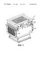
- FIG. 1is a perspective view of the apparatus for thermally cycling samples of a biological material according to the invention
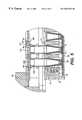
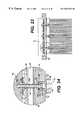
- FIG. 2is a front sectional view of the apparatus of FIG. 1;
- FIG. 3is another perspective view of the apparatus of FIG. 1;
- FIG. 4is a perspective cutaway view of the apparatus of FIG. 1;
- FIG. 5is a partial front sectional view of the apparatus of FIG. 1 with sample tubes included;
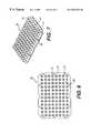
- FIG. 6is a top view of a thermal block assembly of the apparatus of FIG. 1;
- FIG. 7is a perspective view of the thermal block assembly of FIG. 6;
- FIG. 8is a perspective sectional view of a sample well of the apparatus of FIG. 1;
- FIG. 9is a perspective view of a sensor cup of the apparatus of FIG. 1;
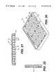
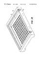
- FIG. 10is a perspective view of a heat sink of the apparatus of FIG. 1;
- FIG. 11is a bottom view of the heat sink of FIG. 10;
- FIG. 12is a top view of a solid state heater of the apparatus of FIG. 1;
- FIG. 13is a side view of the solid state heater of FIG. 12;
- FIG. 14is a perspective view of the solid state heater of FIG. 12;
- FIG. 15is a top view of a spacer bracket with the solid state heaters of FIGS. 12-14 installed;
- FIG. 16is a top perspective view of the spacer bracket of the apparatus of FIG. 1;
- FIG. 17is a bottom perspective view of the spacer bracket of FIG. 16;
- FIG. 18is a top view of the heat sink, a bottom resistive heater, and the solid state heaters of the apparatus of FIG. 1;
- FIG. 19is a bottom view of a thermal block plate and the solid state heaters of the apparatus of FIG. 1;
- FIG. 20is a bottom perspective view of a thermal block assembly insulating cover of the apparatus of FIG. 1;
- FIG. 21is a side sectional view of the thermal block assembly insulating cover of FIG. 20;
- FIG. 22is a front sectional view of the thermal block assembly insulating cover of FIG. 20;
- FIG. 23is a side sectional view along a plurality of attachment screws of the apparatus of FIG. 1;
- FIG. 24is a magnified view of a portion of FIG. 23;
- FIG. 25is a bottom view of a top resistive element heater of the apparatus of FIG. 1;
- FIG. 26is a perspective view of the top insulating cover of the apparatus of FIG. 1;
- FIG. 27is a bottom view of the top insulating cover of FIG. 26;
- FIG. 28is a perspective view of a top insulating cover assembly of the apparatus of FIG. 1;
- FIG. 29is a perspective view of a top insulating plate of the apparatus of FIG. 1;
- FIG. 30is a top view of the top insulating plate of FIG. 29 .
- an apparatus for thermally cycling samples of a biological material in the form of a biological reaction mixture such as DNAincludes a thermal block assembly including a plurality of sample wells for receiving sample tubes of a biological reaction mixture.
- the apparatus 10 for thermally cycling samples of DNAincludes a thermal block assembly 20 .
- Thermal block assembly 20includes a flat thermal block plate 22 and a plurality of sample wells 24 for receiving tubes with samples of DNA, as best shown in FIGS. 2, 6 and 7 .
- Thermal block plate 22is substantially rectangular and is of sufficient size to accommodate a plurality of sample wells on the top surface, but could be of other shapes such as for example circular.
- the plate 22accommodates 96 sample wells in an eight by twelve grid. It is to be understood that the number of sample wells can be varied depending on the specific application requirements. For example, the sample wells could be arranged to form a grid which is sixteen by twenty-four, thereby accommodating 384 sample wells.
- the sample wells 24are conical in shape, as shown in FIG. 8 .
- the walls 25 of the tubeare conical, and extend at an angle to the flat plate 22 .
- the bottom 26 of the interior of the sample wellis rounded.
- the bottom of each sample wellis attached to the thermal block plate 22 . It should be understood that the sample wells could have any number of shapes, such as for example, cylindrical, so that the inner surface of the sample wells closely mates with the sample tube inserted inside.
- FIG. 5shows a partial cut-away cross section with sample tubes 140 placed in the sample wells 24 .
- Each sample well 24is sized to fit the sample tube 140 exterior so that there will be substantial contact area between the plastic sample tube 140 and the interior portion of the sample well wall 25 to enhance the heat transfer to the DNA sample in the plastic sample tube and reduce differences between the DNA mixture and sample well temperatures.
- the plastic sample tubeincludes a conical wall portion 142 which closely mates with the sample well wall 25 .
- the plastic sample tubesare available in three common forms in the preferred embodiment: 1) single tubes; 2) strips of eight tubes which are attached to one another; and 3) tube trays with 96 attached sample tubes.
- the apparatusis preferably designed to be compatible with any of these three designs.
- a typical sample tubehas a fluid volume capacity of approximately 200 ⁇ l, however other sizes and configurations can be envisaged.
- the fluid volume typically used in an experimentis substantially less than the 200 ⁇ l sample tube capacity.
- sample holding structuressuch as slides, partitions, beads, channels, reaction chambers, vessels, surfaces, or any other suitable device for holding a sample can be envisaged.
- sample holding structurefor biological reaction mixtures
- samples to be placed in the sample holding structureare not limited to biological reaction mixtures. Samples could include any type of product for which it is desired to heat and/or cool, such as cells, tissues, microorganisms or non-biological product.
- each sample tube 140also has a corresponding cap 146 for maintaining the biological reaction mixture in the sample tube.
- the caps 146are typically inserted inside the top cylindrical surface 148 of the sample tube 140 . These caps are relatively clear so that light can be transmitted through the cap. Similar to the sample tubes 140 , the caps 146 are typically made of molded polypropylene, however, other suitable materials are acceptable.
- Each cap 146has a thin, flat, plastic optical window 148 on the top surface of the cap. The optical window in each cap allows radiation such as excitation light to be transmitted to the DNA samples and emitted fluorescent light from the DNA to be transmitted back to an optical detection system during cycling.
- a biological probecan be placed in the DNA samples so that flourescent light is transmitted in and emitted out as the strands replicate during each cycle.
- a suitable optical detection systemcan detect the emission of radiation from the sample. The detection system can thus measure the amount of DNA which has been produced as a function of the emitted flourescent light. Data can be provided from each well and analyzed by a computer.
- the thermal block plate 22is provided with mounting holes 27 , as best shown in FIGS. 6 and 7. Attachment screws or other fasteners pass through each of the holes 27 . The arrangement of these fasteners will be discussed in greater detail below.
- the thermal block assembly 20further includes a plurality of sensor cups 28 , as best shown in FIGS. 6, 7 and 9 .
- the sensor cups 28are positioned adjacent the outer periphery of the thermal block plate 22 .
- four sensor cups 28are positioned outside the grid of sample wells 24 .
- the details of the solid state heating deviceswill be discussed below.
- the apparatusis provided with four solid state heating devices, therefore it is appropriate to use at least four thermal sensors. If more solid state heating devices were used, then it would be desirable to have more sensor cups.
- Each of the solid state heating devicesmay heat at slightly different temperatures, therefore the provision of a thermal sensor in a sensor cup 28 for each solid state heater increases thermal block temperature uniformity.
- the sensor cups 28each include a thermistor or other suitable temperature sensor positioned to measure the temperature of the thermal block plate.
- Alternate temperature sensorsinclude thermocouples or RTDs. Each type of temperature sensor has advantages and disadvantages.
- the temperature of the thermal block plate at the sensor cupcorresponds to the temperature of adjacent sample wells.
- the temperature data from the cupis sent to a controller which will then adjust the amount of heat provided by the heating devices.
- the thermal block plate 22 , sample wells 24 , and sensor cups 28are preferably composed of copper alloy with a finish of electroplated gold over electroless nickel, although other materials having a high thermal conductivity are also suitable. This composition increases the thermal conductivity between the components and prevents corrosion of the copper alloy, resulting in faster heating and cooling transition times. It is important for the thermal block assembly to have a thermal conductivity chosen to increase the temperature uniformity of the sample wells. As previously discussed, increasing thermal block temperature uniformity increases the accuracy of the DNA cycling techniques. It is desirable to obtain substantial thermal block temperature uniformity among the sample wells. For example, in a thermal block assembly with 96 sample wells with 200 ⁇ l capacity sample wells being used to thermally cycle samples of DNA, it is typically desirable to obtain temperature uniformity of approximately plus or minus 0.5 degrees C.
- the sample wells 24 and sensor cups 28are fixed to the top surface of the thermal block plate.
- the sample wells 24 and sensor cups 28are silver brazed to the thermal block plate 22 in an inert atmosphere, although other suitable methods for fixing the sample wells and sensor cups are known.
- the design of the present inventionis well suited for a fixing method involving ultrasonic welding. In this ultrasonic welding method, the sample wells are attached to the thermal plate using pressure and mechanical vibration energy. Many copper alloys and other non-ferrous alloys are well suited for this method. Ultrasonic welding provides the advantages of excellent repeatability and minimal impact to the original material properties because no significant heating is required.
- Another sample well fixing methodinvolves a copper casting process. Copper casting would require design changes in the sample well geometry. Although the casting process would be less expensive than the silver brazing method, there will be a loss in performance. Therefore, the silver brazing method described above is the preferred method for fixing the sample wells to the thermal block plate.
- the apparatusfurther includes a heat sink for transferring heat from the thermal block assembly to ambient air located adjacent to the heat sink.
- heat sink 30is provided for transferring heat from the thermal block assembly 20 .
- Heat sink 30includes a plurality of parallel, rectangular fins 32 extending downward from a base 34 .
- the heat base 34 and rectangular fins 32are preferably made from aluminum, although other suitable materials may be used.
- the heat sink 30allows the thermal block assembly 20 to be quickly and efficiently cooled during thermal cycling. Heat is transferred from the thermal block assembly 20 to the heat sink 30 due to the heat sink's lower temperature. The heat which flows to the heat sink is dissipated from the heat sink rectangular fins 32 to the ambient air which flows between the fins.
- the heat sink base 34includes attachment holes 36 through which fasteners such as attachment screws pass.
- the attachment holes 36extend from the top surface 60 to the bottom surface or underside 35 of the heat sink base 34 . The details of the attachment means will be described later.
- the apparatusfurther includes at least one solid state heater to provide heat to the thermal block assembly.
- solid state heaters 40are provided in order to supply heat to the thermal block assembly.
- the solid state heaters 40are preferably thermoelectric heaters such as Peltier heaters, but could also be any other type of heater such as a resistive heater.
- Peltier heatersare preferred because they can be controlled to exhibit a temperature gradient, as will be discussed later.
- the other advantage of Peltier heatersis that Peltier heaters are capable of providing cooling. The Peltier heaters can be controlled to cool the thermal block assembly below the ambient temperature.
- This coolingis not possible with other types of heaters such as a resistive element heater.
- This coolingallows the Peltier heaters to pump heat from the thermal block assembly to the heat sink.
- the Peltier heatersachieve cooling by changing the electrical current polarity into the Peltier heaters.
- the convective air current across the heat sinktransfers this heat which has been pumped to the heat sink to the ambient air.
- Each Peltier heaterincludes two lead wires 41 for supplying an electrical current through the heater.
- Each Peltier heateralso includes a first side 42 located closer to the thermal block plate 22 , and a second side 44 located closer to the heat sink base 34 .
- the first side 42will be hot and the second side 44 will be cool.
- the first side 42will be cool and the second side 44 will be hot.
- the hot and cold sidesare changed with the reversal of the current flow.
- a plurality of these heatersare located between the heat sink 30 and thermal block assembly 20 .
- the number of Peltier heaterscan vary depending on the specific heating and cooling requirements for the particular application. In the illustrated embodiment, four Peltier heaters are provided.
- Peltier heaterscan be modified.
- the systemcould be altered such that a rectangular Peltier heater could be used, alone or in combination with other rectangular or square Peltier heaters.
- Other shapes of Peltier heaterscould also be envisaged.
- Other types of Peltier heaterssuch as two-stage Peltier heaters, could also be envisaged.
- a two-stage Peltier heaterhas two levels or stages of heat pumping elements which are separated by a plate. These two-stage Peltier heaters are typically used in order to create very large temperature differences between the cold and hot sides. Peltier heaters with more than 2 pumping stages are also possible.
- each of the Peltier heatersis controlled independently of the other Peltier heaters. Independent heater control is desirable because each Peltier heater may have slightly different temperature characteristics, that is, if identical currents were placed in each of the Peltier heaters, each of the Peltier heaters could have a slightly different temperature response. Therefore, by providing temperature control using multiple sensors and sensor cups for the heaters, each Peltier heater can be separately controlled to enhance uniform temperature distribution to the thermal block assembly. Alternately, the independent temperature control can be used to set up a plurality of temperature zones with different temperatures.
- the apparatusfurther includes a spacer, such as a bracket for positioning the at least one solid state heater.
- a spacersuch as a bracket for positioning the at least one solid state heater.
- the spacer bracket 46is provided above and adjacent to the heat sink base 34 .
- the spacer bracketis preferably composed of polyetherimide, although other suitable materials are also acceptable.
- a spacer bracket cover 49is included above and adjacent to the spacer bracket 46 .
- the spacer bracket 46includes attachment holes 48 through which fasteners such as the attachment screws pass.
- the spacer bracket 46includes openings 52 in which the Peltier heaters 40 are positioned. As shown in FIG. 15, for example, two Peltier heaters 40 can be positioned in each of the two openings 52 .
- the lead wires 41 of the Peltier heatersare positioned so that they will be received in slots 47 of the spacer bracket. The placement of the lead wires 41 in the slots 47 will prevent significant movement by the Peltier heaters in the bracket, while still allowing slight movement.
- the slots 47are dimensioned to be slightly larger than the lead wires 47 to allow such slight movement.
- the spacer brackethas bosses 54 around the attachment holes 48 which have a thickness such that the thermal block assembly will be placed in compression. By placing the thermal block assembly in compression, heat transfer can occur more efficiently. For example, by imparting a compressive force, the Peltier heaters, heat sink, thermal block plate, and thermal interface materials will be placed firmly in contact with one another. It should be understood that the spacer bracket can be designed to accommodate a variety of different Peltier heater configurations. The spacer bracket and Peltier heaters are designed so that a minimum amount of heat is transferred to the spacer bracket. As shown in FIG. 15, a small gap is provided between the outside edge of the Peltier heaters 40 and the inner surfaces 51 of the inner walls of the openings 52 . The gap reduces the amount of contact between the Peltier heaters and the spacer bracket, thereby reducing the amount of heat loss to the spacer bracket.
- the apparatusfurther includes a heater located below the solid state heaters for heating a bottom portion of the solid state heaters.
- a plurality of resistive element heaters 58are provided on the top surface 60 of the heat sink base 34 . It should be understood that any other type of suitable heater may also be used.
- resistive element heaters 58are placed at the front and back edges of the top surface 60 of the heat sink.
- the front of the apparatusis the portion of the apparatus located adjacent the air exit plate on the left side of the apparatus in FIG. 1 .
- the back of the apparatusis the portion of the apparatus located adjacent the opposite air exit plate which cannot be seen in FIG. 1 .
- the positioning of the front and the back resistive element heatershelps to provide thermal block temperature uniformity in a manner described in further detail below.
- the Peltier heaters 40are the primary source used for heating the thermal block plate 22 . However, the Peltier heaters are primarily located towards the central portion of the apparatus, in that the Peltier heaters are located in the openings 52 of the spacer bracket 46 as best shown in FIGS. 15-18. Therefore, in the absence of the bottom resistive heater, the Peltier heaters would be directed primarily to the central portion of the thermal block plate, with the risk of decreasing temperatures at the edges of the thermal block plate, such as the front and back portions.
- the apparatus of the present inventionincludes an arrangement for heating the thermal block at the front and back edges to provide thermal block temperature uniformity.
- Resistive heaters 58are provided for improving thermal block plate temperature uniformity. The resistive heaters do this by heating the edges of the heat sink on which they are attached. This results in a desired temperature gradient in the heat sink 30 .
- the resistive heaters 58do not directly heat the front and back portions of the thermal block through convection or direct contact.
- the resistive heaters 58also do not contact the Peltier heaters 40 .
- the resistive heaters 58create the temperature gradient in the heat sink by increasing the temperature of the heat sink at the front and back of the heat sink base 34 .
- the Peltier heaterstransfer a greater amount of heat at the front and back edges of the Peltier heater which are adjacent to the heat sink at the locations closest to the resistive heaters 58 .
- the hot side of the Peltier heaterswill have a hotter temperature at the portion of the Peltier heater closest to the resistive heater. Therefore, the front and back portions of the thermal block plate will receive a greater amount of heat transfer than the central portion of the thermal block plate. This will ensure that the front and back portions of the thermal block plate which are not adjacent to the Peltier heaters will receive heat transfer by conduction through the thermal block plate and thermal interface elements which will be discussed below. It should be understood that the number and position of the resistive element heaters is exemplary only and will vary depending on the design requirements of the apparatus.
- At least one bottom thermal interface elementis provided between the bottom of the Peltier heaters and the top surface of the heat sink.
- bottom thermal interface elements 62are flat plates positioned between the bottom of the Peltier heaters 40 and the top surface 60 of the heat sink.
- a bottom thermal interface element 62is provided for each of the openings 52 in the spacer element. Therefore, the two Peltier heaters in the front opening are provided with a plate of thermal interface material, and the two Peltier heaters in the back opening are provided with a second plate of thermal interface material.
- Each bottom thermal interface element 62is slightly smaller than its respective opening 52 in the spacer element.
- Each bottom thermal interface elementroughly corresponds to the size of the surface area of the two Peltier heaters which it covers. For example, in the top view shown in FIG. 18, the bottom thermal interface elements are located immediately underneath the Peltier heaters. Only a small portion of the bottom thermal interface element can be shown because the Peltier heaters cover the entire surface area of the bottom thermal interface elements except for the portion located in between the two Peltier heaters sharing the same opening, as shown in FIG. 18 .
- the bottom thermal interface elements 62have a high rate of thermal conductivity in order to provide effective heat transfer between heat sink and Peltier heaters.
- the materialis relatively soft so that the plates 62 can be compressed. This allows the Peltier heaters to have a more evenly distributed surface area with the top of the heat sink.
- An example of the type of material to be used in the thermal interface elementsis a boron nitride filled silicone rubber. Any other type of suitable material is also acceptable.
- At least one top thermal interface elementis provided between the top of the Peltier heaters and the bottom of the thermal block plate.
- a pair of top thermal interface elements 64are located between the top of the Peltier heaters and the bottom of the thermal block plate 22 .
- the top thermal interface elementsconduct the heat from the first side 42 of the Peltier heaters 40 to the bottom of the thermal block plate 22 .
- the top thermal interface elements 64are similar in shape and size to the bottom thermal interface elements 62 , except for the additional provision of thermal interface wings 65 on the thermal interface elements. The wings are located on the front and back side of each Peltier heater.
- the wings 65provide heat transfer to the areas of the thermal block plate 22 outside of the Peltier heaters.
- the wings 65effectively conduct the additional heat that is generated in the heat sink and Peltier heaters at the front and back edges due to the bottom resistive heaters.
- the wingsdistribute this heat to the front and back edges of the thermal block plate. This increases thermal block temperature uniformity.
- the top thermal interface elements 64are composed of the same material with the relatively high rate of thermal conductivity as the bottom thermal interface elements 62 .
- any number of interface elementsincluding only one, could be used.
- the provision of the top and bottom thermal interface elementsalso allows the Peltier heaters 40 to “float” between the thermal block plate 22 and the heat sink base 34 .
- the compressible thermal interface materialprovides for effective heat transfer among the surfaces while also uniformly loading the Peltier heaters in compression.
- the use of the compressible thermal interface materialincreases cycle life and reliability of the Peltier heaters.
- the thermal interface materialimproves the reliability of the system by affecting the compressive load imparted onto each Peltier heater. Any structural compressive loading forces are dampened and uniformly distributed into the Peltier heaters due to the thickness and elastomeric characteristics of the thermal interface material.
- the apparatusfurther includes a first insulating cover for insulating the thermal block assembly.
- first insulating cover 70is provided for insulating the thermal block assembly 20 .
- the first insulating coveris preferably composed of polyetherimide, although other suitable materials are also acceptable.
- First insulating cover 70is in the shape of a block having an inner surface 72 with a plurality of cylindrical sample well openings 74 . Each sample well opening 74 corresponds to a sample well 24 on the thermal block assembly 20 .
- the sample wells 24are encapsulated within their respective sample well opening 74 .
- the depth of the sample wells openings 74is almost as long as the sample wells 24 .
- the cylindrical opening 74extends for a substantial length of the sample well positioned inside the cylindrical opening. Therefore, the sample wells 24 are almost completely surrounded by the first insulating cover.
- the first insulating cover 70achieves the insulation of the sample wells of the thermal block assembly in two main ways. First, the insulating cover substantially surrounds the thermal block assembly, thereby minimizing the difference in temperature between the thermal block assembly and air 79 in and around the thermal block assembly, as best shown in FIG. 5 . The first insulating cover 70 reduces the amount of air surrounding the thermal block assembly. Second, the first insulating cover 70 reduces the convective heat transfer coefficient along the thermal block assembly surfaces because the first insulating cover reduces the amount of natural convective air currents.
- the first insulating coverfurther includes tube holes 77 .
- Tube holes 77are provided at the end of each sample well opening 74 .
- Each tube hole 77accommodates the passage of a sample tube 140 into a sample well as best shown in FIG. 5 .
- the first insulating coverfurther includes projections 78 .
- the projections 78are located at predetermined locations of the inner surface 72 of the first insulating cover in order to provide proper spacing between the interior surface of the first insulating cover and the top surface of the thermal block plate 22 .
- the projections 78are also sized and located in order to provide adequate pressure between the thermal block assembly and the thermal interface material.
- the projections 78contact the top surface of the plate 22 .
- the first insulating cover 70further includes a plurality of bosses 76 with attachment holes 75 for passage of the attachment screws.
- the attachment holesextend partly into the first insulating cover as shown in FIG. 22 .
- the means for attaching the various components described abovewill now be described. It is important that the means for attaching the various components does not result in significant heat transfer away from the thermal block assembly to the outside of the components. Any heat transfer which occurs from the thermal block assembly should occur through the thermal block plate, thermal interface elements, solid state heaters and heat sink in order to maximize temperature uniformity. These elements are designed to have uniform heating and cooling characteristics so that no one area of the thermal block plate will be cooled any faster than another area.
- attachment fastenersmust be provided in order to attach the first insulating cover, thermal block plate, thermal interface elements, spacer bracket, Peltier heaters, and heat sink base.
- the attachment fasteners of the present inventionhave been designed to minimize the heat transfer that occurs through the attachment fasteners.
- each attachment screw 160includes a threaded portion and a head 164 in order to impart a compressive force on the attachment screw and the components between the first insulating cover 70 and the heat sink.
- the threaded portion of each screw 160threads into an internal threaded portion 162 of the first insulating cover 70 .
- the internal threaded portion 162 of the first insulating cover 70extends from the boss 76 on the inside surface 72 of the first insulating cover.
- each attachment screwthen passes through the spaces between the sample wells, through the attachment hole 27 in the thermal block plate 22 , through the attachment hole 48 in the spacer bracket 46 , and through the attachment hole 36 in the heat sink base 34 .
- the attachment screwpreferably passes through holes 27 , 48 and 36 without making contact with the sides of the attachment holes.
- the attachment screw 160is preferably made out of stainless steel, although any number of suitable materials are also acceptable.
- a bore 166is provided on the underside of the heat sink underside 35 for the head 164 of the attachment screw 160 . By providing the bore 166 on the underside 35 of the heat sink, the attachment screw is spaced from the convection currents which occur along the underside of the heat sink.
- the means for attaching the various componentsfurther includes an insulating washer 168 positioned between the underside 35 of the heat sink base and the head of the screw.
- the insulating washeris preferably made out of mylar, although other materials with good insulating properties are also acceptable.
- the mylar washerprevents the attachment screw from making contact with the heat sink 30 . This lack of contact prevents heat from the thermal block plate 22 from being transferred to the heat sink 30 via the attachment screws. This is especially important because the heat sink 30 is normally at a lower temperature than the thermal block plate 22 .
- a standard split locking washer 170may also be provided between the surfaces of the insulating washer 168 and the attachment screw head 164 . The split locking washer 170 helps to maintain the screw torque and preload during the thermal cycling.
- a plastic screw cap 172is provided for plugging the bore 166 .
- the plastic screw cap 172surrounds the head 164 of the attachment screw, and helps to prevent heat from being transferred from the head of the attachment screw to the ambient air that flows along the underside of the heat sink. Insulating screw caps 172 are therefore provided over the top of each attachment screw head in order to prevent heat transfer to the ambient air.
- These insulating screw capscan be made out of a variety of materials such as ethylene vinyl acetate.
- the apparatusfurther includes a resistive element heater located above the thermal block assembly to provide heat to the thermal block assembly.
- a resistive element heaterlocated above the thermal block assembly to provide heat to the thermal block assembly.
- top resistive element heater 80is placed above the thermal block assembly 20 .
- the top resistive element heater 80is a flat rectangular plate as shown in FIG. 25, with a heating area 86 around the outside periphery. The surface of the plate is spaced from the top of the first insulating cover 70 so that the sample tubes 140 can be accommodated between the resistive element heater 80 and the first insulating cover 70 as best shown in FIG. 5 .
- the surface 82 of the resistive element heaterhas a plurality of holes 84 for allowing emitted radiation from the samples to pass out of the apparatus to be detected by a suitable detection system.
- the surface 82 of the resistive element heateris lined with a thin layer of insulating material such as silicone rubber.
- the thin insulating layer on the surface of the resistive element heatercontacts the top of the caps 146 of the sample tubes 140 to reduce the likelihood of condensation occurring on the tops of the caps. This is best shown in FIG. 5 . Condensation on the caps may increase errors in the data and degrade the accuracy of the experiment.
- the resistive element heateralso imparts a compressive load on the sample tubes. This compressive load enhances the uniform contact between the outer surfaces of the sample tubes and the inner surfaces of the sample wells. The compressive load is imparted as a result of the securing means on the second insulating cover which will be discussed below.
- An aluminum contact plate 81shown for example in FIG. 5, is provided between the resistive heater element 80 and the second insulating cover which will be described below.
- the apparatusfurther includes a second insulating cover including a securing means for securing the DNA sample tubes into the thermal block by imparting a uniform compressive load, and an insulator plate for insulating the thermal block assembly.
- second insulating cover 90is provided on the top of the apparatus.
- Second insulating coverincludes a securing means 92 which will also be referred to as the top shell.
- Securing means 92is a bracket with a top flange 94 and a side flange 96 .
- the securing means 92is preferably made out of 20% glass-filled polycarbonate, however, any other suitable insulation material is acceptable.
- the top flange 94is located immediately above the second insulating plate, which will be described below.
- a hinge 96is provided so that the second insulating cover 90 and top resistive element heater 80 can be pivoted relative to the spacer bracket cover 49 , spacer bracket 46 , thermal block assembly 20 , and first insulating cover 70 .
- Hinge 96includes a top hinge bracket 98 attached to the second insulating cover 90 , and a bottom hinge bracket 100 attached to the spacer bracket cover 49 .
- Second insulating coverincludes an insulation plate 110 as shown in FIGS. 1-5 and 28 - 30 .
- Insulation plate 110has a plurality of holes 112 corresponding to the sample wells. The holes allow radiation to be emitted into and out of the DNA sample as previously discussed.
- the insulation plateprovides insulation for the top resistive element heater 80 , first insulation cover 70 , and thermal block assembly 20 .
- the insulation plate 110prevents heat loss through the top of the apparatus, thus promoting thermal block temperature uniformity.
- the insulation plateis preferably made out of 20% glass-filled polycarbonate, however, any other suitable insulation material is acceptable.
- the apparatusfurther includes a radial fan to provide air to the heat sink.
- a radial fan 118is provided adjacent the bottom fan duct 120 .
- the bottom fan ducthas a air inlet opening 122 through which ambient air enters the apparatus.
- the circulating airflows upward along the interior of the central fan duct 124 .
- the circulating airthen enters the spaces between the heat duct fins 32 and flow along the underside 35 of the heat sink 30 .
- the heat sinktransfers heat to the circulating air which then passes out of the apparatus through fan air exit plates 126 .
- the fan air exit plates 126are bolted onto flanges 128 of the central fan duct.
- the present inventionis designed to increase the cycle life and reliability of the Peltier heaters.
- An additional way in which the reliability of the Peltier heaters is improvedis by matching the thermal coefficient of expansion of the materials used for the structural components surrounding the Peltier heaters.
- the copper thermal block plate, first insulating cover, spacer bracket and heat sink base platehave all been designed to have very similar thermal coefficients of expansion.
- the Peltier heatersare structurally loaded with forces resulting from the expansion and contraction of these components. By providing similar thermal coefficients of expansion to these materials, the expansion and contraction forces on the Peltier heaters are minimized, thereby improving the cycle life of the solder joints within the Peltier heaters.
- a suitable computer devicesuch as that includes a microprocessor, can be incorporated into the control electronics of the apparatus.
- the microprocessorcontrols the temperature of the apparatus and the amount of time that the apparatus is at each temperature in the thermal cycle.
- the microprocessorcan be programmed to conduct the appropriate thermal cycle for each type of sample material.
- the operation of the apparatusis described below.
- the second insulating cover 90 of the apparatusis opened up by pivoting about the hinges 96 .
- a tray of disposable sample tubesare placed on top of the first insulating cover 70 so that the DNA in the sample tubes are positioned in the sample wells.
- the second insulating cover 90is then closed.
- thermocyclingis controlled by a controller.
- the DNAwill undergo a pre-programmed thermocycling process of raising and lowering temperatures in order to replicate the strands of DNA.
- the temperature of the thermal block assemblyis measured at at least one location.
- the controllercalculates the desired temperature of the thermal block assembly at the particular time.
- the desired temperatureis then compared to the measured temperature. If the measured temperature is less than the desired temperature, heating of the thermal block assembly will occur.
- Heating the thermal block assemblycomprises several steps.
- the first stepis imparting a first heat rate via at least one first heater, a portion of the first heat rate being transferred to the thermal block assembly.
- the second stepis imparting a second heat rate via a second heater, a portion of the second heat rate being transferred to the first heater.
- the third stepis imparting a third heat rate via a third heater, a portion of the third heat rate being transferred to the top of the sample tubes in order to reduce the likelihood of condensation occurring on the top of sample tubes. It is understood that all three of these steps may be performed simultaneously.
- the heat rate output of each of the plurality of first heatersmay be independently controlled. This will allow the controller to monitor the sensor cup temperatures so that all of the sensor cups have a substantially equal temperature. Likewise, if a plurality of second heaters is provided, the heat rate output of each of the second heaters may also be independently controlled.
- the thermal block assemblywill be cooled. This is done by reversing the current on the Peltier heaters in order to turn them into coolers, and by also imparting a cooling convection current on the heat sink which is thermally coupled to the thermal block assembly to provide heat transfer from the thermal block assembly to ambient air adjacent the heat sink.
- a radial fanmay be provided for providing the convection current to the heat sink.
- the cyclecontinues by repeating the steps of measuring, calculating, and comparing until the predetermined thermal cycle for the samples of biological reaction mixture is completed. After the proper number of cycles have been performed, the top insulating cover will be opened and the DNA sample tubes will be removed from the sample wells.
- the thermal cycling apparatuscould also be modified to incorporate a temperature gradient means across the thermal block.
- a thermal cycling apparatus with a temperature gradient meansis used to discover the optimum polymerase chain reaction annealing stage temperatures.
- the apparatus of the present inventionis primarily focused towards producing the DNA via polymerase chain reactions once these temperatures are known.
- the apparatus for thermal cyclingcould be modified to include a temperature gradient means or independent temperature zones.
Landscapes
- Health & Medical Sciences (AREA)
- Chemical & Material Sciences (AREA)
- Life Sciences & Earth Sciences (AREA)
- Biochemistry (AREA)
- General Health & Medical Sciences (AREA)
- Molecular Biology (AREA)
- Clinical Laboratory Science (AREA)
- Chemical Kinetics & Catalysis (AREA)
- Apparatus Associated With Microorganisms And Enzymes (AREA)
Abstract
Description
Claims (38)
Priority Applications (5)
| Application Number | Priority Date | Filing Date | Title |
|---|---|---|---|
| US09/364,051US6657169B2 (en) | 1999-07-30 | 1999-07-30 | Apparatus for thermally cycling samples of biological material with substantial temperature uniformity |
| AU64928/00AAU6492800A (en) | 1999-07-30 | 2000-07-26 | Apparatus for thermally cycling samples of biological material |
| PCT/US2000/020178WO2001008801A1 (en) | 1999-07-30 | 2000-07-26 | Apparatus for thermally cycling samples of biological material |
| US10/691,874US7005617B2 (en) | 1999-07-30 | 2003-10-23 | Apparatus and method for thermally cycling samples of biological material with substantial temperature uniformity |
| US11/272,903US20060065652A1 (en) | 1999-07-30 | 2005-11-14 | Method for thermally cycling samples of biological material with substantial temperature uniformity |
Applications Claiming Priority (1)
| Application Number | Priority Date | Filing Date | Title |
|---|---|---|---|
| US09/364,051US6657169B2 (en) | 1999-07-30 | 1999-07-30 | Apparatus for thermally cycling samples of biological material with substantial temperature uniformity |
Related Child Applications (1)
| Application Number | Title | Priority Date | Filing Date |
|---|---|---|---|
| US10/691,874DivisionUS7005617B2 (en) | 1999-07-30 | 2003-10-23 | Apparatus and method for thermally cycling samples of biological material with substantial temperature uniformity |
Publications (2)
| Publication Number | Publication Date |
|---|---|
| US20020030044A1 US20020030044A1 (en) | 2002-03-14 |
| US6657169B2true US6657169B2 (en) | 2003-12-02 |
Family
ID=23432809
Family Applications (3)
| Application Number | Title | Priority Date | Filing Date |
|---|---|---|---|
| US09/364,051Expired - LifetimeUS6657169B2 (en) | 1999-07-30 | 1999-07-30 | Apparatus for thermally cycling samples of biological material with substantial temperature uniformity |
| US10/691,874Expired - LifetimeUS7005617B2 (en) | 1999-07-30 | 2003-10-23 | Apparatus and method for thermally cycling samples of biological material with substantial temperature uniformity |
| US11/272,903AbandonedUS20060065652A1 (en) | 1999-07-30 | 2005-11-14 | Method for thermally cycling samples of biological material with substantial temperature uniformity |
Family Applications After (2)
| Application Number | Title | Priority Date | Filing Date |
|---|---|---|---|
| US10/691,874Expired - LifetimeUS7005617B2 (en) | 1999-07-30 | 2003-10-23 | Apparatus and method for thermally cycling samples of biological material with substantial temperature uniformity |
| US11/272,903AbandonedUS20060065652A1 (en) | 1999-07-30 | 2005-11-14 | Method for thermally cycling samples of biological material with substantial temperature uniformity |
Country Status (3)
| Country | Link |
|---|---|
| US (3) | US6657169B2 (en) |
| AU (1) | AU6492800A (en) |
| WO (1) | WO2001008801A1 (en) |
Cited By (39)
| Publication number | Priority date | Publication date | Assignee | Title |
|---|---|---|---|---|
| US20030072685A1 (en)* | 2001-10-11 | 2003-04-17 | Goldman Jeffrey A. | Heat conducting sample block |
| US20030143120A1 (en)* | 2002-01-25 | 2003-07-31 | Waldemar Ruediger | Parallel chemistry reactor with interchangeable vessel carrying inserts |
| US20040009525A1 (en)* | 2002-06-24 | 2004-01-15 | Masahiro Kawaguchi | Nucleic-acid probe substrate, system for temperature control of the substrate, and gene detection method making use of the same |
| US20040014080A1 (en)* | 2000-09-06 | 2004-01-22 | Michifumi Tanga | Solid supports having surface-treated layer formed thereon |
| US20040028562A1 (en)* | 2000-11-29 | 2004-02-12 | Thomas Greve | Device for controlling the temperature of microcomponents |
| US20040065655A1 (en)* | 2002-10-02 | 2004-04-08 | Stratagene | Flexible heating cover assembly for thermal cycling of samples of biological material |
| US20040149725A1 (en)* | 1999-07-30 | 2004-08-05 | Stratagene | Apparatus and method for thermally cycling samples of biological material with substantial temperature uniformity |
| US20060104865A1 (en)* | 2004-11-12 | 2006-05-18 | Jacobs Merrit N | Heating and cooling multiple containers or multi-chamber containers |
| DE102005027407B3 (en)* | 2005-06-13 | 2006-11-09 | Eppendorf Ag | Thermo cycler, for polymerase chain reactions, comprises a cover over the holding zone for the reaction vessels with a sealing wall adjusted longitudinally by an external setting unit |
| US20080061429A1 (en)* | 2006-09-08 | 2008-03-13 | Finnzymes Instruments Oy | Instruments and method relating to thermal cycling |
| WO2008091626A1 (en)* | 2007-01-22 | 2008-07-31 | Wafergen, Inc. | Apparatus for high throughput chemical reactions |
| US20090018776A1 (en)* | 2007-07-10 | 2009-01-15 | Taylor Roger H | System and method for normalizing data in nucleic acid amplification procedures |
| US20090173472A1 (en)* | 2007-10-15 | 2009-07-09 | Biocision, Llc | Temperature transfer stand |
| US20100081191A1 (en)* | 2008-09-26 | 2010-04-01 | Marlow Industries, Inc. | Anisotropic heat spreader for use with a thermoelectric device |
| US7767447B2 (en)* | 2007-06-21 | 2010-08-03 | Gen-Probe Incorporated | Instruments and methods for exposing a receptacle to multiple thermal zones |
| US7833709B2 (en) | 2004-05-28 | 2010-11-16 | Wafergen, Inc. | Thermo-controllable chips for multiplex analyses |
| US20100288059A1 (en)* | 2009-05-14 | 2010-11-18 | Streck, Inc. | Specimen container, system, and method |
| US20110039305A1 (en)* | 2008-02-20 | 2011-02-17 | Streck, Inc. | Thermocycler and sample vessel for rapid amplification of dna |
| US20110136109A1 (en)* | 2009-12-09 | 2011-06-09 | Roche Diagnostics Operations, Inc. | System And Method For Cycling Liquid Samples Through A Series Of Temperature Excursions |
| EP2339320A1 (en) | 2005-01-25 | 2011-06-29 | Oscillogy LLC | Temperature controller for small fluid samples having different heat capacities |
| US20110269641A1 (en)* | 2009-03-13 | 2011-11-03 | Illumina Corporation | Methods and systems for controlling liquids in multiplex assays |
| US8372340B2 (en) | 2005-10-19 | 2013-02-12 | Luminex Corporation | Apparatus and methods for integrated sample preparation, reaction and detection |
| US8596340B1 (en)* | 2010-10-13 | 2013-12-03 | Horn-Barber Technologies, LLC | Apparatus for heating liquid samples for analysis |
| US20140130518A1 (en)* | 2011-06-16 | 2014-05-15 | Kanagawa University | Temperature control device and temperature element |
| US20140165645A1 (en)* | 2012-12-13 | 2014-06-19 | Biocision, Llc | Thermal energy transfer device |
| US20140373643A1 (en)* | 2013-06-25 | 2014-12-25 | Dale D. Timm, Jr. | Internally illuminated heating and/or chilling bath |
| US9017617B2 (en) | 2005-10-19 | 2015-04-28 | Luminex Corporation | Cassette for sample preparation |
| USD735881S1 (en)* | 2012-10-22 | 2015-08-04 | Qiagen Gaithersburg, Inc. | Tube strip holder for automated processing systems |
| US9180461B2 (en) | 2012-10-22 | 2015-11-10 | Qiagen Gaithersburg, Inc. | Condensation-reducing incubation cover |
| US9248422B2 (en) | 2010-02-23 | 2016-02-02 | Luminex Corporation | Apparatus and methods for integrated sample preparation, reaction and detection |
| US9273344B2 (en) | 2006-12-27 | 2016-03-01 | Luminex Corporation | Instrument for cassette for sample preparation |
| US9737891B2 (en) | 2011-06-01 | 2017-08-22 | Streck, Inc. | Rapid thermocycler system for rapid amplification of nucleic acids and related methods |
| US9919314B2 (en)* | 2010-08-31 | 2018-03-20 | Canon U.S. Life Sciences, Inc. | Air cooling systems and methods for microfluidic devices |
| US9932632B2 (en) | 2012-08-10 | 2018-04-03 | Streck, Inc. | Real-time optical system for polymerase chain reaction |
| US10006861B2 (en) | 2013-06-28 | 2018-06-26 | Streck, Inc. | Devices for real-time polymerase chain reaction |
| US10641772B2 (en) | 2015-02-20 | 2020-05-05 | Takara Bio Usa, Inc. | Method for rapid accurate dispensing, visualization and analysis of single cells |
| US20210293451A1 (en)* | 2018-08-10 | 2021-09-23 | Ez Pack Water Ltd | System and Method for Storage of Renewable Energy as Hot or Cold Water in Flexible Heating Tanks |
| US11460405B2 (en) | 2016-07-21 | 2022-10-04 | Takara Bio Usa, Inc. | Multi-Z imaging and dispensing with multi-well devices |
| US12070198B2 (en) | 2010-06-18 | 2024-08-27 | Cool Lab, Llc | Specimen freezing rate regulator device |
Families Citing this family (61)
| Publication number | Priority date | Publication date | Assignee | Title |
|---|---|---|---|---|
| EP1377379B1 (en)* | 2001-03-13 | 2006-10-18 | PamGene B.V. | Incubator system provided with a temperature control system |
| EP1409137A2 (en)* | 2001-07-13 | 2004-04-21 | University of British Columbia | Thermal cycling methods and apparatus |
| SE0203781D0 (en)* | 2002-12-19 | 2002-12-19 | Alphahelix Ab | Holder and method for cooling or heating samples |
| US7507376B2 (en)* | 2002-12-19 | 2009-03-24 | 3M Innovative Properties Company | Integrated sample processing devices |
| US20040241048A1 (en)* | 2003-05-30 | 2004-12-02 | Applera Corporation | Thermal cycling apparatus and method for providing thermal uniformity |
| US7659109B2 (en)* | 2004-05-17 | 2010-02-09 | Applied Biosystems, Llc | Pasting edge heater |
| US20070116444A1 (en)* | 2005-06-16 | 2007-05-24 | Sratagene California | Heat blocks and heating |
| DE102006062714B4 (en)* | 2006-03-09 | 2013-02-21 | Eppendorf Ag | Device for mixing laboratory vessel contents |
| DE102006011370A1 (en)* | 2006-03-09 | 2007-09-20 | Eppendorf Ag | Device for mixing, in particular, laboratory vessel contents with a sensor |
| US8232091B2 (en)* | 2006-05-17 | 2012-07-31 | California Institute Of Technology | Thermal cycling system |
| EP1898218A3 (en)* | 2006-09-05 | 2009-10-07 | FUJIFILM Corporation | Cold insulation unit and measurement apparatus |
| AU2011244916B2 (en)* | 2007-06-21 | 2013-07-18 | Gen-Probe Incorporated | Instruments and method for exposing a receptacle to multiple thermal zones |
| EP2060324A1 (en) | 2007-11-13 | 2009-05-20 | F.Hoffmann-La Roche Ag | Thermal block unit |
| CN101932927B (en)* | 2007-12-06 | 2012-07-04 | 新加坡科技研究局 | Integrated device for performing and monitoring chemical reactions and method of operation thereof |
| WO2009108530A2 (en)* | 2008-02-26 | 2009-09-03 | Mallinckrodt Inc. | Radiopharmaceutical heater |
| WO2010035063A1 (en)* | 2008-09-23 | 2010-04-01 | Koninklijke Philips Electronics N.V. | Thermocycling device |
| ES2892342T3 (en) | 2009-01-08 | 2022-02-03 | It Is International Ltd | Optical system to detect light from polymerase chain reactions |
| CN202830041U (en)* | 2009-04-03 | 2013-03-27 | Illumina公司 | Device for heating biological sample |
| EP2473893B1 (en) | 2009-09-01 | 2021-07-28 | Life Technologies Corporation | Thermal block assemblies and instruments providing low thermal non-uniformity for rapid thermal cycling |
| CN201837588U (en)* | 2009-09-09 | 2011-05-18 | 海利克斯公司 | Optical system for multiple reactions |
| US9081004B2 (en)* | 2009-09-28 | 2015-07-14 | International Business Machines Corporation | Circuit for detecting analytes via nanoparticle-labeled substances with electromagnetic read-write heads |
| EP2338599B1 (en)* | 2009-12-23 | 2013-11-20 | Eppendorf Ag | Laboratory apparatus with an arrangement for the tempering of samples and method of tempering samples |
| EP2615462B1 (en)* | 2010-11-15 | 2016-12-14 | F. Hoffmann-La Roche AG | Instrument and method for the automated thermal treatment of liquid samples |
| CN105779285B (en)* | 2010-11-17 | 2019-10-18 | 达雅高生命科技有限公司 | Box type testing device and through type detection equipment |
| US9446410B2 (en) | 2010-12-03 | 2016-09-20 | Biofire Defense, Llc | Thermal cycler apparatus with elastomeric adhesive |
| US9304130B2 (en) | 2010-12-16 | 2016-04-05 | International Business Machines Corporation | Trenched sample assembly for detection of analytes with electromagnetic read-write heads |
| US9110478B2 (en) | 2011-01-27 | 2015-08-18 | Genia Technologies, Inc. | Temperature regulation of measurement arrays |
| CN102228845B (en)* | 2011-04-19 | 2013-04-03 | 北京航空航天大学 | Automatic cooling heat sink framework and refrigeration method thereof |
| EP2525211B1 (en) | 2011-05-16 | 2018-01-03 | F. Hoffmann-La Roche AG | Instrument and method for detecting analytes |
| US10928321B2 (en) | 2012-03-09 | 2021-02-23 | Ubiquitome Limited | Portable device for detecting molecule(s) |
| AU2013202793B2 (en)* | 2012-07-31 | 2014-09-18 | Gen-Probe Incorporated | System, method and apparatus for automated incubation |
| US9435800B2 (en) | 2012-09-14 | 2016-09-06 | International Business Machines Corporation | Sample assembly with an electromagnetic field to accelerate the bonding of target antigens and nanoparticles |
| US20140112829A1 (en)* | 2012-10-22 | 2014-04-24 | Qiagen Gaithersburg, Inc. | Tube strip handling and heating apparatus |
| US20160051982A1 (en)* | 2013-03-08 | 2016-02-25 | Otago Innovation Limited | Reaction vessel holder and molecule detection device |
| AU2013202805B2 (en) | 2013-03-14 | 2015-07-16 | Gen-Probe Incorporated | System and method for extending the capabilities of a diagnostic analyzer |
| EP3325161B1 (en) | 2015-07-23 | 2020-10-14 | Cepheid | Thermal control device and methods of use |
| JP6576750B2 (en)* | 2015-09-04 | 2019-09-18 | Phcホールディングス株式会社 | Nucleic acid amplification equipment |
| JP6903638B2 (en)* | 2015-09-15 | 2021-07-14 | ライフ テクノロジーズ コーポレーション | Systems and methods for biological analysis |
| US11583862B2 (en) | 2015-09-15 | 2023-02-21 | Life Technologies Corporation | Systems and methods for biological analysis |
| EP3393665B1 (en)* | 2015-12-22 | 2020-08-12 | Life Technologies Corporation | Thermal cycler systems |
| DE112017004226T5 (en)* | 2016-08-23 | 2019-05-09 | Brio Apps Alphasip, S.L. | Compact thermal cycler and system comprising the thermal cycler |
| EP3552707B1 (en)* | 2016-09-01 | 2020-10-21 | Roche Diagnostics GmbH | Assembly, instrument for performing a temperature-dependent reaction and method for performing a temperature-dependent reaction in an assembly |
| USD855826S1 (en)* | 2017-07-10 | 2019-08-06 | Gen-Probe Incorporated | Receptacle holder |
| CN108020434B (en)* | 2018-01-12 | 2019-03-08 | 北京航空航天大学 | Bottom end splashproof is shot at the target |
| CN108051235B (en)* | 2018-01-12 | 2019-03-08 | 北京航空航天大学 | The double-deck Anti-splash molecule sink structure and its cooling means of ground electric propulsion test |
| CN108240910B (en)* | 2018-01-12 | 2019-03-08 | 北京航空航天大学 | Band cylinder bilayer Anti-splash molsink and its cooling means |
| KR102538826B1 (en)* | 2018-11-12 | 2023-06-02 | 삼성디스플레이 주식회사 | Moisture permeability measuring device |
| US11549731B2 (en) | 2019-01-14 | 2023-01-10 | Bio-Rad Laboratories, Inc. | Heat pump device and assembly |
| KR102009505B1 (en)* | 2019-01-17 | 2019-08-12 | 주식회사 엘지화학 | Module for polymerase chain reaction of sample |
| CN119951603A (en) | 2019-01-30 | 2025-05-09 | 生命技术控股私人有限公司 | Bioanalysis systems and methods |
| MX2021011348A (en) | 2019-03-22 | 2021-10-13 | Siemens Healthcare Diagnostics Inc | Biological sample analyzer with accelerated thermal warming. |
| AU2020245293B2 (en) | 2019-03-22 | 2022-02-24 | Siemens Healthcare Diagnostics Inc. | Biological sample analyzer with cold consumable detection |
| JP7296477B2 (en)* | 2019-03-22 | 2023-06-22 | シーメンス・ヘルスケア・ダイアグノスティックス・インコーポレイテッド | Biological sample analyzer with forced air convection plenum |
| EP4061533B1 (en) | 2019-11-22 | 2025-07-16 | Bio-Rad Laboratories, Inc. | Thermal management for thermal cyclers using air tubes |
| EP3858487A1 (en)* | 2020-01-30 | 2021-08-04 | Roche Diagnostics GmbH | Thermal unit and device for thermal cycling biological samples, and method for thermal cycling biological samples using such device |
| US20210237088A1 (en)* | 2020-02-03 | 2021-08-05 | dxImpact LLC | Energy efficient configuration for thermal cycling device |
| CN111269823B (en)* | 2020-03-10 | 2020-11-03 | 杭州博日科技股份有限公司 | Thermal cycling device and PCR instrument |
| EP4146398A1 (en)* | 2020-05-08 | 2023-03-15 | Life Technologies Holdings Pte Limited | Biological analysis systems and methods |
| CN115698327A (en)* | 2020-06-15 | 2023-02-03 | 生物辐射实验室股份有限公司 | Temperature uniformity across PCR sample blocks |
| FR3130646A1 (en)* | 2021-11-15 | 2023-06-23 | Biomerieux | Automated Biological Sample Preparation System |
| DE102023204533B4 (en)* | 2023-05-15 | 2025-03-27 | Fraunhofer-Gesellschaft zur Förderung der angewandten Forschung eingetragener Verein | Procedures for conducting biochemical tests on samples |
Citations (27)
| Publication number | Priority date | Publication date | Assignee | Title |
|---|---|---|---|---|
| US4195131A (en)* | 1977-03-09 | 1980-03-25 | Papas Gary R | Environmentally controlled unit |
| US4365665A (en)* | 1978-11-17 | 1982-12-28 | Sumitomo Precision Products Company, Ltd. | Heat sink |
| US4865986A (en)* | 1988-10-06 | 1989-09-12 | Coy Corporation | Temperature control apparatus |
| WO1989012502A1 (en) | 1988-06-23 | 1989-12-28 | Lep Scientific Limited | Biochemical reaction machine |
| US4950608A (en)* | 1989-04-25 | 1990-08-21 | Scinics Co., Ltd. | Temperature regulating container |
| EP0438883A2 (en) | 1989-12-22 | 1991-07-31 | Beckman Instruments, Inc. | Heated cover device |
| US5061630A (en)* | 1988-05-13 | 1991-10-29 | Agrogen Foundation, Seyffer & Co. & Ulrich C. Knopf | Laboratory apparatus for optional temperature-controlled heating and cooling |
| EP0488769A2 (en) | 1990-11-29 | 1992-06-03 | The Perkin-Elmer Corporation | Thermal cycler for automatic performance of the polymerase chain reaction with close temperature control |
| JPH05168459A (en)* | 1991-12-20 | 1993-07-02 | Orion Mach Co Ltd | Device for heating and cooling nucleic acid amplifier |
| US5255976A (en)* | 1992-07-10 | 1993-10-26 | Vertex Pharmaceuticals Incorporated | Temperature gradient calorimeter |
| JPH07308183A (en)* | 1994-05-17 | 1995-11-28 | Sanyo Electric Co Ltd | Apparatus for sterilizing incubator |
| US5525300A (en)* | 1993-10-20 | 1996-06-11 | Stratagene | Thermal cycler including a temperature gradient block |
| US5616301A (en)* | 1993-09-10 | 1997-04-01 | Hoffmann-La Roche Inc. | Thermal cycler |
| JPH09322755A (en)* | 1996-06-05 | 1997-12-16 | Rikagaku Kenkyusho | Incubator for small samples |
| US5785926A (en) | 1995-09-19 | 1998-07-28 | University Of Washington | Precision small volume fluid processing apparatus |
| US5813233A (en) | 1994-12-28 | 1998-09-29 | Sharp Kabushiki Kaisha | Thermoelectric cooling device and system thereof |
| WO1998043740A2 (en)* | 1997-03-28 | 1998-10-08 | The Perkin-Elmer Corporation | Improvements in thermal cycler for pcr |
| US5819842A (en)* | 1991-12-05 | 1998-10-13 | Potter; Derek Henry | Method and apparatus for temperature control of multiple samples |
| US5849208A (en)* | 1995-09-07 | 1998-12-15 | Microfab Technoologies, Inc. | Making apparatus for conducting biochemical analyses |
| US6004512A (en)* | 1995-12-08 | 1999-12-21 | Mj Research | Sample cartridge slide block |
| WO2000032312A1 (en)* | 1998-11-30 | 2000-06-08 | Hybaid Limited | Thermal cycler |
| US6093370A (en)* | 1998-06-11 | 2000-07-25 | Hitachi, Ltd. | Polynucleotide separation method and apparatus therefor |
| US6106784A (en)* | 1997-09-26 | 2000-08-22 | Applied Chemical & Engineering Systems, Inc. | Thawing station |
| US6337435B1 (en)* | 1999-07-30 | 2002-01-08 | Bio-Rad Laboratories, Inc. | Temperature control for multi-vessel reaction apparatus |
| US6489111B1 (en)* | 1998-02-10 | 2002-12-03 | Toyo Kohan Co., Ltd. | Apparatus and methods for immobilized DNA library preparation and gene amplification |
| US20020179590A1 (en)* | 2000-12-12 | 2002-12-05 | 3-Dimensional Pharmaceuticals, Inc. | Microtiter plate with integral heater |
| US6558947B1 (en)* | 1997-09-26 | 2003-05-06 | Applied Chemical & Engineering Systems, Inc. | Thermal cycler |
Family Cites Families (11)
| Publication number | Priority date | Publication date | Assignee | Title |
|---|---|---|---|---|
| US4534941A (en)* | 1981-12-04 | 1985-08-13 | Beckman Instruments, Inc. | Analytical instrument thermoelectric temperature regulator |
| JPH03295185A (en)* | 1990-04-13 | 1991-12-26 | Matsushita Electric Ind Co Ltd | Heating element |
| ATE193973T1 (en)* | 1992-12-16 | 2000-07-15 | Colgate Palmolive Co | ORAL COMPOSITION AGAINST PLAQUE, GINGIVITIS AND CARIES |
| US5410130A (en)* | 1994-04-20 | 1995-04-25 | Ericomp, Inc. | Heating and temperature cycling |
| DE29623597U1 (en)* | 1996-11-08 | 1999-01-07 | Eppendorf - Netheler - Hinz Gmbh, 22339 Hamburg | Temperature control block with temperature control devices |
| US6906292B2 (en)* | 1998-10-29 | 2005-06-14 | Applera Corporation | Sample tray heater module |
| JP3293594B2 (en)* | 1999-06-29 | 2002-06-17 | 住友電気工業株式会社 | Apparatus and method for heating protective member of optical fiber fusion spliced part |
| US6770482B1 (en)* | 1999-07-16 | 2004-08-03 | General Electric | Method and apparatus for rapid screening of multiphase reactions |
| US6657169B2 (en)* | 1999-07-30 | 2003-12-02 | Stratagene | Apparatus for thermally cycling samples of biological material with substantial temperature uniformity |
| US6730883B2 (en)* | 2002-10-02 | 2004-05-04 | Stratagene | Flexible heating cover assembly for thermal cycling of samples of biological material |
| US20040241048A1 (en)* | 2003-05-30 | 2004-12-02 | Applera Corporation | Thermal cycling apparatus and method for providing thermal uniformity |
- 1999
- 1999-07-30USUS09/364,051patent/US6657169B2/ennot_activeExpired - Lifetime
- 2000
- 2000-07-26WOPCT/US2000/020178patent/WO2001008801A1/enactiveApplication Filing
- 2000-07-26AUAU64928/00Apatent/AU6492800A/ennot_activeAbandoned
- 2003
- 2003-10-23USUS10/691,874patent/US7005617B2/ennot_activeExpired - Lifetime
- 2005
- 2005-11-14USUS11/272,903patent/US20060065652A1/ennot_activeAbandoned
Patent Citations (31)
| Publication number | Priority date | Publication date | Assignee | Title |
|---|---|---|---|---|
| US4195131A (en)* | 1977-03-09 | 1980-03-25 | Papas Gary R | Environmentally controlled unit |
| US4365665A (en)* | 1978-11-17 | 1982-12-28 | Sumitomo Precision Products Company, Ltd. | Heat sink |
| US5061630A (en)* | 1988-05-13 | 1991-10-29 | Agrogen Foundation, Seyffer & Co. & Ulrich C. Knopf | Laboratory apparatus for optional temperature-controlled heating and cooling |
| WO1989012502A1 (en) | 1988-06-23 | 1989-12-28 | Lep Scientific Limited | Biochemical reaction machine |
| US4865986A (en)* | 1988-10-06 | 1989-09-12 | Coy Corporation | Temperature control apparatus |
| US4950608A (en)* | 1989-04-25 | 1990-08-21 | Scinics Co., Ltd. | Temperature regulating container |
| EP0438883A2 (en) | 1989-12-22 | 1991-07-31 | Beckman Instruments, Inc. | Heated cover device |
| US5475610A (en) | 1990-11-29 | 1995-12-12 | The Perkin-Elmer Corporation | Thermal cycler for automatic performance of the polymerase chain reaction with close temperature control |
| EP0488769A2 (en) | 1990-11-29 | 1992-06-03 | The Perkin-Elmer Corporation | Thermal cycler for automatic performance of the polymerase chain reaction with close temperature control |
| US5710381A (en)* | 1990-11-29 | 1998-01-20 | The Perkin-Elmer Corporation | Two piece holder for PCR sample tubes |
| US5602756A (en) | 1990-11-29 | 1997-02-11 | The Perkin-Elmer Corporation | Thermal cycler for automatic performance of the polymerase chain reaction with close temperature control |
| US5819842A (en)* | 1991-12-05 | 1998-10-13 | Potter; Derek Henry | Method and apparatus for temperature control of multiple samples |
| JPH05168459A (en)* | 1991-12-20 | 1993-07-02 | Orion Mach Co Ltd | Device for heating and cooling nucleic acid amplifier |
| US5255976A (en)* | 1992-07-10 | 1993-10-26 | Vertex Pharmaceuticals Incorporated | Temperature gradient calorimeter |
| US5616301A (en)* | 1993-09-10 | 1997-04-01 | Hoffmann-La Roche Inc. | Thermal cycler |
| US5779981A (en)* | 1993-10-20 | 1998-07-14 | Stratagene | Thermal cycler including a temperature gradient block |
| US5525300A (en)* | 1993-10-20 | 1996-06-11 | Stratagene | Thermal cycler including a temperature gradient block |
| JPH07308183A (en)* | 1994-05-17 | 1995-11-28 | Sanyo Electric Co Ltd | Apparatus for sterilizing incubator |
| US5813233A (en) | 1994-12-28 | 1998-09-29 | Sharp Kabushiki Kaisha | Thermoelectric cooling device and system thereof |
| US5849208A (en)* | 1995-09-07 | 1998-12-15 | Microfab Technoologies, Inc. | Making apparatus for conducting biochemical analyses |
| US5785926A (en) | 1995-09-19 | 1998-07-28 | University Of Washington | Precision small volume fluid processing apparatus |
| US6004512A (en)* | 1995-12-08 | 1999-12-21 | Mj Research | Sample cartridge slide block |
| JPH09322755A (en)* | 1996-06-05 | 1997-12-16 | Rikagaku Kenkyusho | Incubator for small samples |
| WO1998043740A2 (en)* | 1997-03-28 | 1998-10-08 | The Perkin-Elmer Corporation | Improvements in thermal cycler for pcr |
| US6106784A (en)* | 1997-09-26 | 2000-08-22 | Applied Chemical & Engineering Systems, Inc. | Thawing station |
| US6558947B1 (en)* | 1997-09-26 | 2003-05-06 | Applied Chemical & Engineering Systems, Inc. | Thermal cycler |
| US6489111B1 (en)* | 1998-02-10 | 2002-12-03 | Toyo Kohan Co., Ltd. | Apparatus and methods for immobilized DNA library preparation and gene amplification |
| US6093370A (en)* | 1998-06-11 | 2000-07-25 | Hitachi, Ltd. | Polynucleotide separation method and apparatus therefor |
| WO2000032312A1 (en)* | 1998-11-30 | 2000-06-08 | Hybaid Limited | Thermal cycler |
| US6337435B1 (en)* | 1999-07-30 | 2002-01-08 | Bio-Rad Laboratories, Inc. | Temperature control for multi-vessel reaction apparatus |
| US20020179590A1 (en)* | 2000-12-12 | 2002-12-05 | 3-Dimensional Pharmaceuticals, Inc. | Microtiter plate with integral heater |
Cited By (88)
| Publication number | Priority date | Publication date | Assignee | Title |
|---|---|---|---|---|
| US20040149725A1 (en)* | 1999-07-30 | 2004-08-05 | Stratagene | Apparatus and method for thermally cycling samples of biological material with substantial temperature uniformity |
| US7005617B2 (en)* | 1999-07-30 | 2006-02-28 | Stratagene California | Apparatus and method for thermally cycling samples of biological material with substantial temperature uniformity |
| US20040014080A1 (en)* | 2000-09-06 | 2004-01-22 | Michifumi Tanga | Solid supports having surface-treated layer formed thereon |
| US20040028562A1 (en)* | 2000-11-29 | 2004-02-12 | Thomas Greve | Device for controlling the temperature of microcomponents |
| US7431891B2 (en) | 2000-11-29 | 2008-10-07 | Merck Patent Gmbh | Device for controlling the temperature of chemical microreactors |
| US20030072685A1 (en)* | 2001-10-11 | 2003-04-17 | Goldman Jeffrey A. | Heat conducting sample block |
| US6893613B2 (en)* | 2002-01-25 | 2005-05-17 | Bristol-Myers Squibb Company | Parallel chemistry reactor with interchangeable vessel carrying inserts |
| US20030143120A1 (en)* | 2002-01-25 | 2003-07-31 | Waldemar Ruediger | Parallel chemistry reactor with interchangeable vessel carrying inserts |
| US20040009525A1 (en)* | 2002-06-24 | 2004-01-15 | Masahiro Kawaguchi | Nucleic-acid probe substrate, system for temperature control of the substrate, and gene detection method making use of the same |
| US7713692B2 (en)* | 2002-06-24 | 2010-05-11 | Canon Kabushiki Kaisha | Nucleic-acid probe substrate, system for temperature control of the substrate, and gene detection method making use of the same |
| US6878905B2 (en) | 2002-10-02 | 2005-04-12 | Stratagene California | Apparatus and method for flexible heating cover assembly for thermal cycling of samples of biological material |
| US20050184042A1 (en)* | 2002-10-02 | 2005-08-25 | Stratagene California | Method and apparatus for cover assembly for thermal cycling of samples |
| US20040065655A1 (en)* | 2002-10-02 | 2004-04-08 | Stratagene | Flexible heating cover assembly for thermal cycling of samples of biological material |
| US6730883B2 (en)* | 2002-10-02 | 2004-05-04 | Stratagene | Flexible heating cover assembly for thermal cycling of samples of biological material |
| US7081600B2 (en) | 2002-10-02 | 2006-07-25 | Stragene California | Method and apparatus for cover assembly for thermal cycling of samples |
| US20040188411A1 (en)* | 2002-10-02 | 2004-09-30 | Stratagene | Apparatus and method for flexible heating cover assembly for thermal cycling of samples of biological material |
| US10718014B2 (en) | 2004-05-28 | 2020-07-21 | Takara Bio Usa, Inc. | Thermo-controllable high-density chips for multiplex analyses |
| US9228933B2 (en) | 2004-05-28 | 2016-01-05 | Wafergen, Inc. | Apparatus and method for multiplex analysis |
| US7833709B2 (en) | 2004-05-28 | 2010-11-16 | Wafergen, Inc. | Thermo-controllable chips for multiplex analyses |
| US9909171B2 (en) | 2004-05-28 | 2018-03-06 | Takara Bio Usa, Inc. | Thermo-controllable high-density chips for multiplex analyses |
| US7799283B2 (en)* | 2004-11-12 | 2010-09-21 | Ortho-Clinical Diagnostics, Inc. | Heating and cooling multiple containers or multi-chamber containers |
| US20060104865A1 (en)* | 2004-11-12 | 2006-05-18 | Jacobs Merrit N | Heating and cooling multiple containers or multi-chamber containers |
| EP2339320A1 (en) | 2005-01-25 | 2011-06-29 | Oscillogy LLC | Temperature controller for small fluid samples having different heat capacities |
| US20080210700A1 (en)* | 2005-06-13 | 2008-09-04 | Eppendorf Ag | Thermocycler |
| DE102005027407B3 (en)* | 2005-06-13 | 2006-11-09 | Eppendorf Ag | Thermo cycler, for polymerase chain reactions, comprises a cover over the holding zone for the reaction vessels with a sealing wall adjusted longitudinally by an external setting unit |
| US10472622B2 (en) | 2005-10-19 | 2019-11-12 | Luminex Corporation | Cassette for sample preparation |
| US10040071B2 (en) | 2005-10-19 | 2018-08-07 | Luminex Corporation | Apparatus and methods for integrated sample preparation, reaction and detection |
| US9017617B2 (en) | 2005-10-19 | 2015-04-28 | Luminex Corporation | Cassette for sample preparation |
| US9828598B2 (en) | 2005-10-19 | 2017-11-28 | Luminex Corporation | Cassette for sample preparation |
| US8372340B2 (en) | 2005-10-19 | 2013-02-12 | Luminex Corporation | Apparatus and methods for integrated sample preparation, reaction and detection |
| US9624531B2 (en) | 2005-10-19 | 2017-04-18 | Luminex Corporation | Cassette for sample preparation |
| US10646875B2 (en) | 2005-10-19 | 2020-05-12 | Luminex Corporation | Apparatus and methods for integrated sample preparation, reaction and detection |
| US9074250B2 (en) | 2005-10-19 | 2015-07-07 | Luminex Corporation | Apparatus and methods for integrated sample preparation, reaction and detection |
| US9539577B2 (en) | 2005-10-19 | 2017-01-10 | Luminex Corporation | Apparatus and methods for integrated sample preparation, reaction and detection |
| US8962306B2 (en) | 2006-09-08 | 2015-02-24 | Thermo Fisher Scientific Oy | Instruments and method relating to thermal cycling |
| EP2377615A1 (en) | 2006-09-08 | 2011-10-19 | Finnzymes Instruments Oy | Heat sink |
| US9718061B2 (en) | 2006-09-08 | 2017-08-01 | Thermo Fisher Scientific Oy | Instruments and method relating to thermal cycling |
| US20080061429A1 (en)* | 2006-09-08 | 2008-03-13 | Finnzymes Instruments Oy | Instruments and method relating to thermal cycling |
| US9856517B2 (en) | 2006-12-27 | 2018-01-02 | Luminex Corporation | Instrument for cassette for sample preparation |
| US9745615B2 (en) | 2006-12-27 | 2017-08-29 | Luminex Corporation | Instrument for cassette for sample preparation |
| US9273344B2 (en) | 2006-12-27 | 2016-03-01 | Luminex Corporation | Instrument for cassette for sample preparation |
| US9434939B2 (en) | 2006-12-27 | 2016-09-06 | Luminex Corporation | Instrument for cassette for sample preparation |
| US10047391B2 (en) | 2006-12-27 | 2018-08-14 | Luminex Corporation | Instrument for cassette for sample preparation |
| US10214767B2 (en) | 2006-12-27 | 2019-02-26 | Luminex Corporation | Instrument for cassette for sample preparation |
| EP2109627A4 (en)* | 2007-01-22 | 2014-07-23 | Wafergen Inc | APPARATUS FOR IMPLEMENTING HIGH-PERFORMANCE CHEMICAL REACTIONS |
| US9951381B2 (en) | 2007-01-22 | 2018-04-24 | Takara Bio Usa, Inc. | Apparatus for high throughput chemical reactions |
| US8252581B2 (en) | 2007-01-22 | 2012-08-28 | Wafergen, Inc. | Apparatus for high throughput chemical reactions |
| US9132427B2 (en) | 2007-01-22 | 2015-09-15 | Wafergen, Inc. | Apparatus for high throughput chemical reactions |
| WO2008091626A1 (en)* | 2007-01-22 | 2008-07-31 | Wafergen, Inc. | Apparatus for high throughput chemical reactions |
| US11643681B2 (en) | 2007-01-22 | 2023-05-09 | Takara Bio Usa, Inc. | Apparatus for high throughput chemical reactions |
| US7767447B2 (en)* | 2007-06-21 | 2010-08-03 | Gen-Probe Incorporated | Instruments and methods for exposing a receptacle to multiple thermal zones |
| US20090018776A1 (en)* | 2007-07-10 | 2009-01-15 | Taylor Roger H | System and method for normalizing data in nucleic acid amplification procedures |
| US20090173472A1 (en)* | 2007-10-15 | 2009-07-09 | Biocision, Llc | Temperature transfer stand |
| US8460621B2 (en)* | 2007-10-15 | 2013-06-11 | Biocision, Llc | Temperature transfer stand |
| US9034635B2 (en) | 2008-02-20 | 2015-05-19 | Streck, Inc. | Thermocycler and sample vessel for rapid amplification of DNA |
| US20110039305A1 (en)* | 2008-02-20 | 2011-02-17 | Streck, Inc. | Thermocycler and sample vessel for rapid amplification of dna |
| US20100081191A1 (en)* | 2008-09-26 | 2010-04-01 | Marlow Industries, Inc. | Anisotropic heat spreader for use with a thermoelectric device |
| US9194774B2 (en) | 2009-03-13 | 2015-11-24 | Illumina, Inc. | Methods and systems for controlling liquids in multiplex assays |
| US8765486B2 (en) | 2009-03-13 | 2014-07-01 | Illumina Corporation | Methods and systems for controlling liquids in multiplex assays |
| US20110269641A1 (en)* | 2009-03-13 | 2011-11-03 | Illumina Corporation | Methods and systems for controlling liquids in multiplex assays |
| US8338187B2 (en)* | 2009-03-13 | 2012-12-25 | Illumina, Inc. | Methods and systems for controlling liquids in multiplex assays |
| US20100291536A1 (en)* | 2009-05-14 | 2010-11-18 | Streck, Inc. | Sample processing cassette, system, and method |
| US20100288059A1 (en)* | 2009-05-14 | 2010-11-18 | Streck, Inc. | Specimen container, system, and method |
| US20110136109A1 (en)* | 2009-12-09 | 2011-06-09 | Roche Diagnostics Operations, Inc. | System And Method For Cycling Liquid Samples Through A Series Of Temperature Excursions |
| US9931636B2 (en) | 2010-02-23 | 2018-04-03 | Luminex Corporation | Apparatus and method for integrated sample preparation, reaction and detection |
| US9248422B2 (en) | 2010-02-23 | 2016-02-02 | Luminex Corporation | Apparatus and methods for integrated sample preparation, reaction and detection |
| US12070198B2 (en) | 2010-06-18 | 2024-08-27 | Cool Lab, Llc | Specimen freezing rate regulator device |
| US9919314B2 (en)* | 2010-08-31 | 2018-03-20 | Canon U.S. Life Sciences, Inc. | Air cooling systems and methods for microfluidic devices |
| US9335239B1 (en)* | 2010-10-13 | 2016-05-10 | Horn-Barber Technologies, LLC | Feed system for delivering liquids to an analytical system |
| US9329108B1 (en) | 2010-10-13 | 2016-05-03 | Horn Jr Jack Delaney | Apparatus for handling liquid samples for analysis having a rinse system |
| US10605703B1 (en)* | 2010-10-13 | 2020-03-31 | Jack Delaney Horn, Jr. | Pressurized gas supply system |
| US8596340B1 (en)* | 2010-10-13 | 2013-12-03 | Horn-Barber Technologies, LLC | Apparatus for heating liquid samples for analysis |
| US9737891B2 (en) | 2011-06-01 | 2017-08-22 | Streck, Inc. | Rapid thermocycler system for rapid amplification of nucleic acids and related methods |
| US20140130518A1 (en)* | 2011-06-16 | 2014-05-15 | Kanagawa University | Temperature control device and temperature element |
| US9400128B2 (en)* | 2011-06-16 | 2016-07-26 | Kanagawa University | Temperature control device and temperature element |
| US9932632B2 (en) | 2012-08-10 | 2018-04-03 | Streck, Inc. | Real-time optical system for polymerase chain reaction |
| USD735881S1 (en)* | 2012-10-22 | 2015-08-04 | Qiagen Gaithersburg, Inc. | Tube strip holder for automated processing systems |
| US9180461B2 (en) | 2012-10-22 | 2015-11-10 | Qiagen Gaithersburg, Inc. | Condensation-reducing incubation cover |
| US20140165645A1 (en)* | 2012-12-13 | 2014-06-19 | Biocision, Llc | Thermal energy transfer device |
| US10702870B2 (en)* | 2012-12-13 | 2020-07-07 | Biocision, Llc | Thermal energy transfer device |
| US20140373643A1 (en)* | 2013-06-25 | 2014-12-25 | Dale D. Timm, Jr. | Internally illuminated heating and/or chilling bath |
| US11385178B2 (en) | 2013-06-28 | 2022-07-12 | Streck, Inc. | Devices for real-time polymerase chain reaction |
| US11953438B2 (en) | 2013-06-28 | 2024-04-09 | Streck Llc | Devices for real-time polymerase chain reaction |
| US10006861B2 (en) | 2013-06-28 | 2018-06-26 | Streck, Inc. | Devices for real-time polymerase chain reaction |
| US11125752B2 (en) | 2015-02-20 | 2021-09-21 | Takara Bio Usa, Inc. | Method for rapid accurate dispensing, visualization and analysis of single cells |
| US10641772B2 (en) | 2015-02-20 | 2020-05-05 | Takara Bio Usa, Inc. | Method for rapid accurate dispensing, visualization and analysis of single cells |
| US11460405B2 (en) | 2016-07-21 | 2022-10-04 | Takara Bio Usa, Inc. | Multi-Z imaging and dispensing with multi-well devices |
| US20210293451A1 (en)* | 2018-08-10 | 2021-09-23 | Ez Pack Water Ltd | System and Method for Storage of Renewable Energy as Hot or Cold Water in Flexible Heating Tanks |
Also Published As
| Publication number | Publication date |
|---|---|
| WO2001008801A1 (en) | 2001-02-08 |
| US20020030044A1 (en) | 2002-03-14 |
| US7005617B2 (en) | 2006-02-28 |
| US20060065652A1 (en) | 2006-03-30 |
| US20040149725A1 (en) | 2004-08-05 |
| AU6492800A (en) | 2001-02-19 |
Similar Documents
| Publication | Publication Date | Title |
|---|---|---|
| US6657169B2 (en) | Apparatus for thermally cycling samples of biological material with substantial temperature uniformity | |
| US20050184042A1 (en) | Method and apparatus for cover assembly for thermal cycling of samples | |
| US9718061B2 (en) | Instruments and method relating to thermal cycling | |
| US20070116444A1 (en) | Heat blocks and heating | |
| US9776187B2 (en) | Thermal cycler for PCR | |
| US7611674B2 (en) | Device for the carrying out of chemical or biological reactions | |
| EP2913109A1 (en) | Assembly for thermal cycler for PCR | |
| CN115074236B (en) | Temperature control device for PCR instrument, amplification equipment and PCR instrument | |
| JPH02176910A (en) | Temperature controller | |
| US20060199261A1 (en) | Holder and method for cooling or heating samples | |
| US8722394B2 (en) | Laboratory apparatus with an arrangement for the tempering of samples and method of tempering samples | |
| CN112827524A (en) | Thermal cycling device | |
| CN218511223U (en) | Heating base, PCR temperature control assembly and PCR instrument | |
| CN116731842A (en) | Reaction tank device and PCR instrument | |
| WO2022195289A2 (en) | An apparatus and associated methods for thermal cycling | |
| EP1127619B1 (en) | Assembly for thermal cycler for PCR | |
| CN117286025B (en) | Temperature control unit for PCR instrument | |
| CN221674343U (en) | A dry thermostat | |
| CN220467974U (en) | Reaction tank device and PCR instrument | |
| US20240109070A1 (en) | Device for heating sample | |
| US20230193367A1 (en) | Method for multiplying dna, rotation device and system for multiplying dna | |
| JP2005006507A (en) | Incubator | |
| EP4165209A1 (en) | Pcr sample block temperature uniformity |
Legal Events
| Date | Code | Title | Description |
|---|---|---|---|
| AS | Assignment | Owner name:STRATAGENE, CALIFORNIA Free format text:ASSIGNMENT OF ASSIGNORS INTEREST;ASSIGNOR:BROWN, LARRY R.;REEL/FRAME:010483/0902 Effective date:19990825 | |
| STCF | Information on status: patent grant | Free format text:PATENTED CASE | |
| AS | Assignment | Owner name:MERRILL LYNCH BUSINESS FINANCIAL SERVICES INC., IL Free format text:SECURITY INTEREST;ASSIGNOR:STRATAGENE CORPORATION;REEL/FRAME:014926/0078 Effective date:20040121 | |
| AS | Assignment | Owner name:MERILL LYNCH BUSINESS FINANCIAL SERVICES INC., ILL Free format text:SECURITY AGREEMENT;ASSIGNOR:STRATAGENE CALIFORNIA;REEL/FRAME:015167/0632 Effective date:20040121 | |
| AS | Assignment | Owner name:TCW SPECIAL CREDITS FUND V-THE PRINCIPAL FUND C/O Free format text:SECURITY AGREEMENT;ASSIGNOR:STRATAGENE CALIFORNIA, FORMERLY KNOWN AS STRATAGENE;REEL/FRAME:014981/0654 Effective date:20040203 | |
| AS | Assignment | Owner name:TCW SPECIAL CREDITS FUND V - THE, CALIFORNIA Free format text:SECURITY AGREEMENT;ASSIGNOR:STRATAGENE CALIFORNIA, FORMERLY KNOWN AS STRATAGENE;REEL/FRAME:014981/0660 Effective date:20040203 | |
| AS | Assignment | Owner name:STRATAGENE CALIFORNIA, CALIFORNIA Free format text:CHANGE OF NAME;ASSIGNOR:STRATAGENE;REEL/FRAME:015320/0873 Effective date:20031209 | |
| REMI | Maintenance fee reminder mailed | ||
| FPAY | Fee payment | Year of fee payment:4 | |
| SULP | Surcharge for late payment | ||
| AS | Assignment | Owner name:STRATEGENE CALIFORNIA, CALIFORNIA Free format text:RELEASE BY SECURED PARTY;ASSIGNOR:MERRILL LYNCH BUSINESS FINANCIAL SERVICES, INC.;REEL/FRAME:021952/0174 Effective date:20081030 | |
| AS | Assignment | Owner name:STRATEGENE CALIFORNIA, CALIFORNIA Free format text:CORRECTIVE ASSIGNMENT TO CORRECT THE CORRECTIVE ASSIGNMENT TO REMOVE PATENT NUMBER 0030044 PREVIOUSLY RECORDED ON REEL 021952 AND FRAME 0174;ASSIGNOR:MERRILL LYNCH BUSINESS FINANCIAL SERVICES, INC.;REEL/FRAME:022078/0426 Effective date:20081030 | |
| AS | Assignment | Owner name:AGILENT TECHNOLOGIES, INC., COLORADO Free format text:ASSIGNMENT OF ASSIGNORS INTEREST;ASSIGNOR:STRATAGENE CALIFORNIA;REEL/FRAME:024630/0870 Effective date:20100615 | |
| FEPP | Fee payment procedure | Free format text:PAT HOLDER NO LONGER CLAIMS SMALL ENTITY STATUS, ENTITY STATUS SET TO UNDISCOUNTED (ORIGINAL EVENT CODE: STOL); ENTITY STATUS OF PATENT OWNER: LARGE ENTITY | |
| REFU | Refund | Free format text:REFUND - PAYMENT OF MAINTENANCE FEE, 8TH YR, SMALL ENTITY (ORIGINAL EVENT CODE: R2552); ENTITY STATUS OF PATENT OWNER: LARGE ENTITY | |
| FPAY | Fee payment | Year of fee payment:8 | |
| FPAY | Fee payment | Year of fee payment:12 |