US6656410B2 - Recoating system for using high viscosity build materials in solid freeform fabrication - Google Patents
Recoating system for using high viscosity build materials in solid freeform fabricationDownload PDFInfo
- Publication number
- US6656410B2 US6656410B2US10/052,506US5250602AUS6656410B2US 6656410 B2US6656410 B2US 6656410B2US 5250602 AUS5250602 AUS 5250602AUS 6656410 B2US6656410 B2US 6656410B2
- Authority
- US
- United States
- Prior art keywords
- build material
- layer
- oxide
- viscosity state
- high viscosity
- Prior art date
- Legal status (The legal status is an assumption and is not a legal conclusion. Google has not performed a legal analysis and makes no representation as to the accuracy of the status listed.)
- Expired - Fee Related, expires
Links
Images


Classifications
- B—PERFORMING OPERATIONS; TRANSPORTING
- B29—WORKING OF PLASTICS; WORKING OF SUBSTANCES IN A PLASTIC STATE IN GENERAL
- B29C—SHAPING OR JOINING OF PLASTICS; SHAPING OF MATERIAL IN A PLASTIC STATE, NOT OTHERWISE PROVIDED FOR; AFTER-TREATMENT OF THE SHAPED PRODUCTS, e.g. REPAIRING
- B29C41/00—Shaping by coating a mould, core or other substrate, i.e. by depositing material and stripping-off the shaped article; Apparatus therefor
- B29C41/02—Shaping by coating a mould, core or other substrate, i.e. by depositing material and stripping-off the shaped article; Apparatus therefor for making articles of definite length, i.e. discrete articles
- B29C41/12—Spreading-out the material on a substrate, e.g. on the surface of a liquid
- B—PERFORMING OPERATIONS; TRANSPORTING
- B22—CASTING; POWDER METALLURGY
- B22F—WORKING METALLIC POWDER; MANUFACTURE OF ARTICLES FROM METALLIC POWDER; MAKING METALLIC POWDER; APPARATUS OR DEVICES SPECIALLY ADAPTED FOR METALLIC POWDER
- B22F1/00—Metallic powder; Treatment of metallic powder, e.g. to facilitate working or to improve properties
- B22F1/10—Metallic powder containing lubricating or binding agents; Metallic powder containing organic material
- B22F1/107—Metallic powder containing lubricating or binding agents; Metallic powder containing organic material containing organic material comprising solvents, e.g. for slip casting
- B—PERFORMING OPERATIONS; TRANSPORTING
- B22—CASTING; POWDER METALLURGY
- B22F—WORKING METALLIC POWDER; MANUFACTURE OF ARTICLES FROM METALLIC POWDER; MAKING METALLIC POWDER; APPARATUS OR DEVICES SPECIALLY ADAPTED FOR METALLIC POWDER
- B22F10/00—Additive manufacturing of workpieces or articles from metallic powder
- B22F10/10—Formation of a green body
- B22F10/16—Formation of a green body by embedding the binder within the powder bed
- B—PERFORMING OPERATIONS; TRANSPORTING
- B22—CASTING; POWDER METALLURGY
- B22F—WORKING METALLIC POWDER; MANUFACTURE OF ARTICLES FROM METALLIC POWDER; MAKING METALLIC POWDER; APPARATUS OR DEVICES SPECIALLY ADAPTED FOR METALLIC POWDER
- B22F12/00—Apparatus or devices specially adapted for additive manufacturing; Auxiliary means for additive manufacturing; Combinations of additive manufacturing apparatus or devices with other processing apparatus or devices
- B22F12/10—Auxiliary heating means
- B—PERFORMING OPERATIONS; TRANSPORTING
- B22—CASTING; POWDER METALLURGY
- B22F—WORKING METALLIC POWDER; MANUFACTURE OF ARTICLES FROM METALLIC POWDER; MAKING METALLIC POWDER; APPARATUS OR DEVICES SPECIALLY ADAPTED FOR METALLIC POWDER
- B22F12/00—Apparatus or devices specially adapted for additive manufacturing; Auxiliary means for additive manufacturing; Combinations of additive manufacturing apparatus or devices with other processing apparatus or devices
- B22F12/60—Planarisation devices; Compression devices
- B22F12/63—Rollers
- B—PERFORMING OPERATIONS; TRANSPORTING
- B22—CASTING; POWDER METALLURGY
- B22F—WORKING METALLIC POWDER; MANUFACTURE OF ARTICLES FROM METALLIC POWDER; MAKING METALLIC POWDER; APPARATUS OR DEVICES SPECIALLY ADAPTED FOR METALLIC POWDER
- B22F12/00—Apparatus or devices specially adapted for additive manufacturing; Auxiliary means for additive manufacturing; Combinations of additive manufacturing apparatus or devices with other processing apparatus or devices
- B22F12/60—Planarisation devices; Compression devices
- B22F12/67—Blades
- B—PERFORMING OPERATIONS; TRANSPORTING
- B29—WORKING OF PLASTICS; WORKING OF SUBSTANCES IN A PLASTIC STATE IN GENERAL
- B29C—SHAPING OR JOINING OF PLASTICS; SHAPING OF MATERIAL IN A PLASTIC STATE, NOT OTHERWISE PROVIDED FOR; AFTER-TREATMENT OF THE SHAPED PRODUCTS, e.g. REPAIRING
- B29C64/00—Additive manufacturing, i.e. manufacturing of three-dimensional [3D] objects by additive deposition, additive agglomeration or additive layering, e.g. by 3D printing, stereolithography or selective laser sintering
- B29C64/10—Processes of additive manufacturing
- B29C64/106—Processes of additive manufacturing using only liquids or viscous materials, e.g. depositing a continuous bead of viscous material
- B29C64/124—Processes of additive manufacturing using only liquids or viscous materials, e.g. depositing a continuous bead of viscous material using layers of liquid which are selectively solidified
- B—PERFORMING OPERATIONS; TRANSPORTING
- B29—WORKING OF PLASTICS; WORKING OF SUBSTANCES IN A PLASTIC STATE IN GENERAL
- B29C—SHAPING OR JOINING OF PLASTICS; SHAPING OF MATERIAL IN A PLASTIC STATE, NOT OTHERWISE PROVIDED FOR; AFTER-TREATMENT OF THE SHAPED PRODUCTS, e.g. REPAIRING
- B29C64/00—Additive manufacturing, i.e. manufacturing of three-dimensional [3D] objects by additive deposition, additive agglomeration or additive layering, e.g. by 3D printing, stereolithography or selective laser sintering
- B29C64/10—Processes of additive manufacturing
- B29C64/141—Processes of additive manufacturing using only solid materials
- B29C64/153—Processes of additive manufacturing using only solid materials using layers of powder being selectively joined, e.g. by selective laser sintering or melting
- B—PERFORMING OPERATIONS; TRANSPORTING
- B33—ADDITIVE MANUFACTURING TECHNOLOGY
- B33Y—ADDITIVE MANUFACTURING, i.e. MANUFACTURING OF THREE-DIMENSIONAL [3-D] OBJECTS BY ADDITIVE DEPOSITION, ADDITIVE AGGLOMERATION OR ADDITIVE LAYERING, e.g. BY 3-D PRINTING, STEREOLITHOGRAPHY OR SELECTIVE LASER SINTERING
- B33Y10/00—Processes of additive manufacturing
- B—PERFORMING OPERATIONS; TRANSPORTING
- B33—ADDITIVE MANUFACTURING TECHNOLOGY
- B33Y—ADDITIVE MANUFACTURING, i.e. MANUFACTURING OF THREE-DIMENSIONAL [3-D] OBJECTS BY ADDITIVE DEPOSITION, ADDITIVE AGGLOMERATION OR ADDITIVE LAYERING, e.g. BY 3-D PRINTING, STEREOLITHOGRAPHY OR SELECTIVE LASER SINTERING
- B33Y30/00—Apparatus for additive manufacturing; Details thereof or accessories therefor
- B—PERFORMING OPERATIONS; TRANSPORTING
- B33—ADDITIVE MANUFACTURING TECHNOLOGY
- B33Y—ADDITIVE MANUFACTURING, i.e. MANUFACTURING OF THREE-DIMENSIONAL [3-D] OBJECTS BY ADDITIVE DEPOSITION, ADDITIVE AGGLOMERATION OR ADDITIVE LAYERING, e.g. BY 3-D PRINTING, STEREOLITHOGRAPHY OR SELECTIVE LASER SINTERING
- B33Y70/00—Materials specially adapted for additive manufacturing
- B33Y70/10—Composites of different types of material, e.g. mixtures of ceramics and polymers or mixtures of metals and biomaterials
- B—PERFORMING OPERATIONS; TRANSPORTING
- B22—CASTING; POWDER METALLURGY
- B22F—WORKING METALLIC POWDER; MANUFACTURE OF ARTICLES FROM METALLIC POWDER; MAKING METALLIC POWDER; APPARATUS OR DEVICES SPECIALLY ADAPTED FOR METALLIC POWDER
- B22F10/00—Additive manufacturing of workpieces or articles from metallic powder
- B22F10/70—Recycling
- B22F10/73—Recycling of powder
- B—PERFORMING OPERATIONS; TRANSPORTING
- B22—CASTING; POWDER METALLURGY
- B22F—WORKING METALLIC POWDER; MANUFACTURE OF ARTICLES FROM METALLIC POWDER; MAKING METALLIC POWDER; APPARATUS OR DEVICES SPECIALLY ADAPTED FOR METALLIC POWDER
- B22F12/00—Apparatus or devices specially adapted for additive manufacturing; Auxiliary means for additive manufacturing; Combinations of additive manufacturing apparatus or devices with other processing apparatus or devices
- B22F12/40—Radiation means
- B22F12/44—Radiation means characterised by the configuration of the radiation means
- B—PERFORMING OPERATIONS; TRANSPORTING
- B29—WORKING OF PLASTICS; WORKING OF SUBSTANCES IN A PLASTIC STATE IN GENERAL
- B29C—SHAPING OR JOINING OF PLASTICS; SHAPING OF MATERIAL IN A PLASTIC STATE, NOT OTHERWISE PROVIDED FOR; AFTER-TREATMENT OF THE SHAPED PRODUCTS, e.g. REPAIRING
- B29C35/00—Heating, cooling or curing, e.g. crosslinking or vulcanising; Apparatus therefor
- B—PERFORMING OPERATIONS; TRANSPORTING
- B29—WORKING OF PLASTICS; WORKING OF SUBSTANCES IN A PLASTIC STATE IN GENERAL
- B29K—INDEXING SCHEME ASSOCIATED WITH SUBCLASSES B29B, B29C OR B29D, RELATING TO MOULDING MATERIALS OR TO MATERIALS FOR MOULDS, REINFORCEMENTS, FILLERS OR PREFORMED PARTS, e.g. INSERTS
- B29K2105/00—Condition, form or state of moulded material or of the material to be shaped
- B29K2105/0094—Condition, form or state of moulded material or of the material to be shaped having particular viscosity
- Y—GENERAL TAGGING OF NEW TECHNOLOGICAL DEVELOPMENTS; GENERAL TAGGING OF CROSS-SECTIONAL TECHNOLOGIES SPANNING OVER SEVERAL SECTIONS OF THE IPC; TECHNICAL SUBJECTS COVERED BY FORMER USPC CROSS-REFERENCE ART COLLECTIONS [XRACs] AND DIGESTS
- Y02—TECHNOLOGIES OR APPLICATIONS FOR MITIGATION OR ADAPTATION AGAINST CLIMATE CHANGE
- Y02P—CLIMATE CHANGE MITIGATION TECHNOLOGIES IN THE PRODUCTION OR PROCESSING OF GOODS
- Y02P10/00—Technologies related to metal processing
- Y02P10/25—Process efficiency
Definitions
- the inventionrelates in general to a recoating system for use by any solid freeform fabrication technique and, in particular, to a recoating system capable of establishing a uniform layer of a high viscosity build material prior to being solidified by a solid freeform fabrication apparatus.
- the recoating systemis unique in that previously formed layers are not substantially disturbed when applying a new layer of build material to establish a layer of high viscosity build material.
- SFFSolid Freeform Fabrication techniques
- Some SFF techniquesinclude stereolithography, selective deposition modeling, laminated object manufacturing, selective phase area deposition, multi-phase jet solidification, ballistic particle manufacturing, fused deposition modeling, particle deposition, selective laser sintering, and the like.
- complex partsare produced from a modeling material in an additive fashion as opposed to traditional fabrication techniques, which are generally subtractive in nature. For example, in traditional fabrication techniques material is removed by machining operations or shaped in a die or mold to near net shape and then trimmed.
- additive fabrication techniquesincrementally add portions of a build material to specific locations, layer by layer, in order to build a complex part.
- the additive processvaries depending on the technique used, whether by selective deposition of a build material or by selective solidification of a build material.
- SFF technologiestypically utilize a computer graphic representation of a part and a supply of a build material to fabricate the part in successive layers.
- SFF technologieshave many advantages over the prior conventional manufacturing methods. For instance, SFF technologies dramatically shorten the time to develop prototype parts and can quickly produce limited numbers of parts in rapid manufacturing processes. They also eliminate the need for complex tooling and machining associated with-the prior conventional manufacturing methods, including the need to create molds in casting operations. In addition, SFF technologies are advantageous because customized objects can be produced quickly by processing computer graphic data.
- paste materialsare typically applied in the form of a powder, liquid, paste, foam, or gel. Recently, there has developed an interest in utilizing highly viscous paste materials in SEE processes.
- One of the main purposes of using paste materialsis to take advantage of their unique material properties which result in improved properties of the resultant parts formed.
- These pastesmay be obtained by blending a solid charge or filler material in the form of a particulate or powder with a bonding agent.
- the bonding agentis comprised of a photosensitive or heat-cured liquid resin, such as a photopolymerizable resin composed of various combinations of acrylates, epoxies, and vinyl ethers.
- the powdersmay be a polymer, mineral, metallic, ceramic, or any combination thereof.
- Some polymer powders that may be usedare thermoplastics such as ABS. Nylon, polypropylene, polycarbonate, polyethcrsulfate, and the like.
- Some metallic powders that may be usedare steel, steel alloy, stainless steel, aluminum, aluminum alloy, titanium, titanium alloy, copper, tungsten, tungsten carbide, molybdenum, nickel alloy, lanthanum, hafnium, tantalum, rhenium, rubidium, bismuth, cadmium, indium, tin, zinc, cobalt, manganese, chromium, gold, silver, and the like.
- Some ceramics that may be usedare aluminum nitride, aluminum oxide, calcium carbonate, fluoride, magnesium oxide, silicon carbide, silicon dioxide, silicon nitride, titanium carbide, titanium earbonitride, titanium diboride, titanium dioxide, tungsten carbide, tungsten trioxide, zirconia, and zinc suiphide, and the like.
- Some rare earth mineral powders thaimay be used are cerium oxide, dysprosium oxide, erbium oxide, gadolinium oxide, holmium oxide, lutetium oxide, samarium oxide, terbium oxide, yttrium oxide, and the like.
- these pastesmay also be obtained by blending high viscosity photosensitive or heat-cured liquid resins without a solid charge of filler material.
- These high viscosity liquids or pastescan be obtained by blending, for example, photopolymerizable resins composed of acrylates, epoxies, and/or vinyl ethers wit any desired toughening agent, such as, for example, polybutadiene, polyethylene, fiberglass, and the like.
- the pastesare selectively cured layer by layer by exposure to radiation. Generally, the radiation cures the bonding agent in the paste.
- the uncured pastesmay exhibit a linear stress-strain relationship, a Bingham type linear stress-strain relationship having a threshold yield stress to overcome, a non-linear pseudoplastic stress-strain relationship (shear thinning), or a non-linear dilatant fluid stress-strain relationship (shear thickening). It has been discovered that pastes have significant advantages over other materials used in SFF techniques.
- the pastescan contain concentrations of a solid charge material, such as a metallic powder, of greater than 50% by volume, which in turn can produce extremely dense green parts.
- concentrations of a solid charge materialsuch as a metallic powder
- These green partsare well suited for further post processing, such as sintering and infiltration, to produce mechanical properties in the resultant parts that are substantially similar to those achieved by conventional forming techniques such as casting or forging.
- the increasecan far exceed the acceptable viscosity range of the resin coating system, since most conventional stereolithography resin coating systems are generally able to work only with low viscosity liquid resins whose behavior is similar to that of a Newtonian liquid.
- current liquid photopolymer resins used in stereolithographyinclude low molecular weight monomers so as keep the viscosity of the resin within the acceptable viscosity range of the resin coating system.
- the shear stress induced by the recoateris also problematic in regions before and after the recoater encounters solidified portions of the part being built, such as in regions of “trapped volumes” and other part features.
- Some previous attempts to solve the problemhave focused on controlling the application of shear forces on the material during the coating process.
- the recoating system in WO 00/51809utilizes rotating roller members to control the shear forces induced when applying a layer of highly viscous build material.
- highly viscous liquids and pastesare extremely sensitive to the amount of shear stress necessary to properly form a uniform layer, and the proper amount of shear stress to be applied will vary substantially depending on the particular formulation being used.
- thermoplastic photohardenable compositionis applied, in thin layers as a solution, to a film and then allowed to dry. This coated film is then exposed with UV or visible light imagewise from the film side thereby cross-linking the exposed portions.
- Photohardenable compositionspresent a further problem when attempting to achieve high packing densities in filled materials since the photoinitiated reaction employs ultraviolet (UV) light.
- UV lightwill be attenuated by absorption into the metal filled material or by reflection off of the metal filler. This will preclude the binder from hardening throughout the layer of material.
- Layersfor example, can be 50 microns in thickness so the depth of cure must be greater than the thickness of the material layer to bond with the underlying material.
- high packing densities of metallic filled binder materialscan employ bi- and tri-modal metal particles. These particles will effectively act as blocking agents for the transmission of UV light and thereby prevent the layer to layer boundaries of the part from being completely bonded together.
- the present inventionprovides its benefits across a broad spectrum of SFF processes by providing the ability to establish uniform layers of a high viscosity build material that solidify via latent polymerization in order to build a three-dimensional object in a layerwise fashion with enhanced mechanical properties.
- the build materialis transformed by the SFF apparatus in three separate phase states.
- the part being builtbecomes substantially self-supporting and is not substantially affected by the recoating process due to the modifier induced viscosity reduction of the build material during the recoating process.
- the method and apparatus of the present inventionemploys a build material that is applied by a recoating system in a low viscosity state to a working surface to form a layer of build material having a first viscosity value.
- the method and apparatustransforms the layer of build material from the low viscosity state to a high viscosity state having a second viscosity value.
- the transformationis accomplished by removing a viscosity modifier from the layer of build material by applying thermal heat to evaporate the viscosity modifier.
- the first viscosity value of the build materialis less than at least one-half of the second viscosity value.
- the transformation from the low viscosity state to the high viscosity stateis of an amount sufficient that when applying another layer of the build material in the low viscosity state over the layer of build material in the high viscosity state, the transference of shear stress to the layer of build material in the high viscosity state is substantially prevented.
- the transformation from the low viscosity state to the high viscosity stateis such that the second viscosity value of the build material is raised at least to a point where the build material in the layer is substantially self-supporting.
- a build material for use in the present inventioncomprises a combination of a solid charge or filler material and a binder material that forms a paste having a viscosity of approximately greater than 10,000 centipoise at ambient conditions.
- the solid charge or particulate matteris preferably a powder material selected from any combination of polymer, metal, ceramic, or mineral particles.
- the average diameter particle sizemay vary but is preferably approximately less than about 45 ⁇ m.
- the bonding agent or binderis preferably a phototsensitive liquid resin, formulated from an acrylic, epoxy, and/or vinyl ether photopolymerizable based resin, or combination thereof, or a thermally polymerizable material.
- the viscosity modifier that is introduced into the build materialis preferably a solvent such as an acetone or alcohol which can be removed after being dispensed by evaporation.
- the staging area wherein the layers are formedmay be heated in order to assist or speed up the evaporation process.
- the viscosity modified build materialis extruded vertically to a dispensing platform wherein a smoothing member or doctor blade spreads the material over a working surface which may be a previously formed layer or the platform of the SFF apparatus.
- the viscosity modified build materialis gravity fed to a recoating applicator having a distribution roller, guide blade, skive, and doctor blade. The recoating applicator having the distribution roller is desirable for use with build materials that exhibit liquid-like properties when in the low viscosity state.
- Further embodimentsinclude multiple recoating applicators that dispense different build material formulations.
- multiple layers of different materialssuch as highly filled metal layers and highly filled ceramic layers can be formed on a three-dimensional object.
- these highly filled three-dimensional objects produced by the method and apparatus of the present inventionare well suited for further processing, such as sintering and infiltration.
- FIG. 1is diagrammatic side view of a prior art recoating applicator that induces shear stress on a paste material in order to dispense the paste in a uniform layer;
- FIGS. 2 through 7are all diagrammatic side views of the same SFF apparatus for purposes of demonstrating the steps of the present invention recoating system.
- FIG. 8is diagrammatic side view of a recoating applicator for use in practicing the present invention.
- the method of the present inventionprovides the ability of an SFF apparatus to work with a build material that transitions between three separate phase states. More specifically, the principle of the present invention is to reduce the viscosity of a highly viscous build material by introducing a viscosity modifier into the material to establish a first phase state having a first viscosity value, then to apply the thinned material on the working surface of the SFF apparatus, and then to establish a second phase state by removing the viscosity modifier to establish a second viscosity value.
- the third phase stateis a solidified state initiated by selectively solidifying portions of the layer of build material in the second phase state.
- Solidificationis preferably accomplished by exposure to radiation such as, for example, by exposure to actinic radiation produced by a laser and directed by a scanning mirror system, or other radiation that initiates latent polymerization in response to light or heat.
- the second phase stateis a high viscosity state indicative of the original build material formulation.
- the high viscosity state of the build materialmay be a highly viscous liquid, semi-solid, gel, foam, or paste. In one embodiment the viscosity is raised to the second viscosity value at least to a point where the build material in the layer is substantially self-supporting.
- a material that is substantially self-supportingis one that is able to hold its own shape under its own weight and is preferably able to do so when present in successive layers without containment walls.
- all semi-solids, gels, foams, and pastesare substantially self-supporting.
- many high viscosity liquidsare substantially self-supporting due to their thixotropic-type properties, and are particularly so when laid out in thin layers in SFF processes.
- the viscosityis raised to the second viscosity value such that the first viscosity value is at least less than about one-half of the viscosity of the second phase state.
- the transformation of the viscosity of the build materialis accomplished in an amount sufficient that when applying another layer of the build material in the low viscosity state over a layer of build material in the high viscosity state, the transference of shear stress to the layer of build material in the high viscosity state is substantially prevented.
- the transformationmay be accomplished by inducing a chemical transformation on the layer of build material.
- the viscosity modifier or agentis a solvent.
- the layers of thinned build materialare applied with a doctor blade or other smoothing member, and the solvent is removed by evaporation to preferably leave layers of a high viscosity build material on the working surface.
- a solvent extraction processmay be used to remove the solvent, if desired.
- the third phase state of the materialis established when the layer of material is selectively solidified by the SFF apparatus to form the three-dimensional object comprised of build material in the third phase state.
- the three-dimensional objectmay then be separated from the un-solidified build material surrounding the object.
- the recoating systemdispenses the build material on top of previously dispensed material that is in either the second or third phase state or both.
- the viscosity of the first phase stateis substantially reduced compared to the viscosity of the second and third phase states such that problems normally associated with dispensing higher viscosity materials are substantially eliminated.
- a paste build materialconsisting of a multi-functional acrylate monomer liquid and a thennal initiator or a photoinitiator, is filled wit silica powder having a viscosity over 100,000 centipoise at ambient conditions.
- This pasteis then thinned with a viscosity modifier such as MEK (methyl ethel keytone), about 30% by volume, to reduce the viscosity to under 10,000 centipoise at ambient conditions.
- MEKmethyl ethel keytone
- the viscosity modified build materialexhibits liquid-like properties even with the presence of solid particulate matter such as a powder.
- Suitable solvents that may be used as viscosity modifiersare hydrocarbons, aliphatic hydrocarbons, naphtha, mineral oil, aromatic hydrocarbons, benzene, toluene, functional aromatics, O-Cresol, halogenated hydrocarbons, chlorinated solvents, carbon tetrachloride, carbon dioxide, freon, methylene chloride, monohydric alcohols, polyhydric alcohols, phenols, ethers, tetrahydrofrram glycol ethers, ketones, acetone, cyclohexanone, acetophenone, amines, n-Butylamine, N,N-Dimethylaniline, acids, chromic acids, nitric acids, phosphoric acids, inorganics, water, silicon tetrachioride, phosphoric trichioride, esters, N-Butyl acetate, ethyl acetate, nitrogen-containing compounds, nitrates, nitrites
- thermal polymerizationis achieved by use of an appropriate thermal initiator, such as peroxide based initiators.
- WAZO materialsavailable from E. I. du Pont de Nemours & Company are examples of one type of suitable thermal initiators.
- Thermal initiatorsare activated by exposure to infrared (IR) radiation.
- Other thermal initiatorsare Azo-bis-isobutyronitrile thermal initiators also are available commercially from Electron Microscopy Sciences of Fort Washington, Pa. and Azo initiators VA-044, VA-057, VA-085, VA-070 and VA-096 are available from Wako Specialty Chemicals, Ltd.
- Thermal initiators to achieve thermal curinghave also employed salts that are suppliers of cations which initiate cationic curing upon heating.
- Onium and pyridinium saltsprovide cationic species that will initiate thermal curing in epoxide compounds, such as compounds based on styrene oxide moieties linked to organic molecules, oligomers or polymers.
- N-benzylpyridinium and related quaternary ammonium saltsprovide acidic species under heating conditions. Key in achieving successful thermal initiation of curing is that the linked moieties do not hinder the cationic polymerization of the epoxy functionality by steric interaction or the action of a Lewis base. Such reactions are discussed in greater detail in U.S. Pat. No. 6,020,508 issued Feb. 1, 2000.
- Other routes capable of liberating cationic species that will achieve the ring-opening polymerization of styrene oxidesare also known.
- the tackifieris added to improve the film strength between the layers, which has also been found to eliminate curl and delamination problems.
- the tackifierprovides a higher apparent viscosity to the build material and improves the film strength of the material.
- the tackifieris a polymethyl methacrylate in the form of a powder that dissolves in the presence of a solvent selected as the viscosity modifier, although other tackifiers could be used, if desired.
- 15% by weight of a high molecular weight polymethyl methacrylatewas used in the multi-functional acrylate monomer liquid component of the build material.
- Elvacite® 2042Two suitable polymethyl methacrylates are sold under the tradenames Elvacite® 2042, and Elvacite® 2043, and are available from ICI Acrylics of Wilmington, Del.
- Elvacite®is a registered trademark owned by E. I. Du Pont De Nemours & Co., of Wilmington, Del.
- These polymethyl methacrylateswhen used in the build material in about 15% by weight, substantially increased the film strength between layers and eliminated curl problems on the edges of solidified layers.
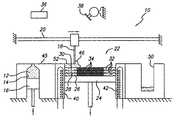
- FIGS. 2 through 7there is illustrated generally at 10 a solid freeform fabrication apparatus for purposes of demonstrating the steps of the present invention recoating system.
- the viscosity modified build material 12is placed in a dispensing container 14 that is dispensed by any suitable means, such as by a piston 16 when it is necessary to deliver the material to be distributed by a smoothing member such as a doctor blade 18 .
- the doctor blade 18reciprocates on a rail system identified by numeral 20 , for dispensing the viscosity modified build material 12 .
- the viscosity modified build material 12is kept relatively cool and contained so that the modifier does not evaporate quickly.
- the viscosity modified build materialmay be delivered to the apparatus with the viscosity modifier already added, or alternatively, the viscosity modifier may be mixed with the build material on the fly by the apparatus, if desired, on an as needed basis.
- Shown generally by numeral 22is a staging area of the SFF apparatus 10 where three-dimensional objects are built.
- the staging area 22has a build platform 24 which can be raised and lowered by the computer control system (not shown).
- three previously formed layers of build materialare shown by numerals 26 , 28 , and 30 respectively.
- Each of these three previously formed layershave portions of build material existing in the second phase state as indicated by numeral 32 , and portions in the third phase state, as indicated by numeral 34 .
- the second phase state of the build materialis substantially self-supporting, typically having a viscosity over 10,000 centipoise at ambient conditions which is established after the modifier is removed by evaporation.
- the third phase stateis a generally solidified state established when the build material is exposed to an appropriate radiation source.
- the preferred approachis to use an actinic radiation source 36 , such as a laser, that is selectively directed via scanning mirrors 38 to solidify the portions of build material in the layers of the three-dimensional object being built, as indicated by numeral 34 .
- an actinic radiation source 36such as a laser
- scanning mirrors 38to solidify the portions of build material in the layers of the three-dimensional object being built, as indicated by numeral 34 .
- a variety of methods of solidifying build materialis well known in the art, such as by the selective focus of a UV beam of energy or by masking and flood exposure to radiation.
- the staging area 22is desirably a relatively hot region so as to promote the evaporative process once the viscosity modified build material 12 is dispensed to form a layer.
- Heater unitsshown by numerals 40 and 42 , may be used to control the temperature in the staging area 22 .
- heater unitsmay also be placed on the platform 24 , or overhead lamps may be provided to control the temperature in the staging area, if desired.
- convection heatersmay be provided to direct a controlled flow of heated gas or air evenly over each layer to promote the evaporation process in order to achieve a desirable evaporation rate that is acceptable for the SFF apparatus to build three-dimensional objects.
- the first step carried out by the SFF apparatus of the present inventionis shown.
- piston 16is displaced vertically to dispense a desired amount of viscosity modified build material in the low viscosity state, shown by numeral 44 , onto dispensing platform 45 .
- the platform 24is lowered one layer thickness in preparation of forming the next layer.
- the next stepis shown where the doctor blade 18 is driven to spread the viscosity modified build material, now indicated by numeral 46 , on top of layer 30 .
- the working surface for the apparatus 10is the surface on which a new layer of build material is to be placed. In FIG.
- the exposed or upper facing surface of the top layer 30is the working surface, however when initially forming an object the first working surface is the upper surface of the build platform 24 . Because the viscosity of the build material in the first phase state is substantially less than that of the second and third phase states, insufficient shear stress is induced by the doctor blade 18 when spreading the material to significantly disturb the build material in the adjacent layer 30 . Uniquely, this solves a significant problem in the prior art of achieving thin uniform layers of highly viscous build materials without causing de-lamination between layers, missing portions of layers, or uneven coating of layers.
- the doctor blade 18is shown having completed its sweep past the staging area 22 , where excess build material 48 is delivered to a catch bin 50 .
- This excess build materialis preferably recycled but may be discarded, if desired, or may be delivered back to the dispensing container 12 provided a negligible amount of modifier evaporated from the material during the sweep.
- a newly formed layer of viscosity modified build materialis established, as indicated by numeral 52 .
- the modifieris removed from the layer to establish a high viscosity state for the layer of build material.
- the ideal modifierwould be one that evaporates relatively quickly at room temperature under atmospheric pressure, and would have a high flash point, although less ideal modifiers may be necessary in order to be compatible with the solid charge or filler materials provided in pastes.
- heater unitssuch as the heated platens shown by numerals 40 and 42 , will be needed in order to assist the evaporation process and reduce the time required for the evaporation process to complete.
- the layer of build materialtransforms into the second phase state wherein the material is substantially self-supporting. This is desired so that the advantages of utilizing highly viscous build materials previously discussed can be realized upon solidifying the material to form a three-dimensional object.
- a condenser systemcan be used to recapture the modifier, if desired, particularly for solvents where it is undesirable to vent them into the atmosphere, and for solvents where it is cost prohibitive to utilize them as consumables.
- a condenser systemmay also be desirable particularly when the volume of solvent to be removed is substantial.
- the radiation source 36 and scanning mirrors 38are then activated by the computer controller (not shown) to direct the beam of radiation to selectively solidify the desired portions of the layer, as indicated by numeral 58 .
- the radiation sourceis a ultraviolet laser which solidifies a photopolymerizable binder material that is present in the build material, although other SFF solidification techniques may be used, if desired.
- the photopolymerizable binder materialmay comprise photopolymerizable resins formulated from any combination of acrylates, epoxies, and/or vinyl ethers.
- the doctor blade 18transports the material and creates a uniform coating of one layer thickness 52 over the build platform or previously formed layer 30 .
- Excess material 48is collected in container 50 .
- the first layer of the partis imaged to solidify portions of the layer 58 .
- Steps 1) through 6)are repeated until the three-dimensional object is completely built.
- the partis removed from the uncured high viscosity material, either manually, or with solvent washing, or with a combination of these methods.
- two or more layers of viscosity modified build materialmay be applied to the working surface before a layer is imaged. If done, it is desirable to remove the modifier from each layer prior to applying the next layer. This multiple layering technique may be desirable when initially starting the build process so that the part does not attach to the platform in the staging area.
- the layerswill not be of uniform thickness.
- the platform in the staging areais lowered 0.005 inch each time. If the build material has 30% of a solvent modifier, by volume, after the solvent evaporates, the resulting layer will be 30% thinner, or 0.0035 inch.
- the recoaterwill deposit more build material during the next cycle, because the platform will displace 0.005 inch, but the resulting distance from the previous layer to the doctor blade will be 0.0065 inch. When the solvent is removed, this layer will be 0.00455 inch thick.
- the recoaterwill deposit an even thicker layer of 0.00695 inch, and when the solvent is removed, this layer will be 0.004865 inch thick. This process will continue, and the layer thickness will asymptotically approach 0.005 inch, and within practical tolerances will be 0.005 inch after a few layers.
- photo-curable binder materialsshrink when they are exposed and cured, which is well documented in stereolithography applications utilizing photocurable liquid resins. Because of this, the layer thickness in an exposed and cured region is slightly less than in an unexposed region. The same effect as described above also adds to the thickness of subsequent layers to correct for this. That is, slightly more material will be deposited in the region of shrinkage.
- a second dispensing meanssuch as a piston
- a second dispensing meanscan be utilize inboard of the catch bin 50 so that the doctor blade 18 operates bidirectionally to distribute build material in both directions and reduce the time required to accomplish recoating.
- a second catch binwould be employed outboard of piston 16 to receive excess build material on the return sweep.
- the collection container 50can be replaced with a second build material dispensing container and piston in order to position fresh material in front of the doctor blade during its return sweep.
- the excess material from the first recoating cyclecan be left directly over the second build material dispensing container, and the doctor blade can be raised over the excess material and position for the return sweep, thereby substantially eliminating the need for the catch bin. Additional viscosity modified build material may then be added to the excess material left above, and the doctor blade can then be swept back to its original position. The process is repeated, with the two containers alternating between dispensing and receiving material.
- a pump or other conveyance meansmay be used to return the material from the collection container 50 back to the dispensing container 14 .
- the doctor bladewould be retracted back to its original position, and therefore would coat in only one direction.
- the amount of viscosity modifier in the build material in the containermay become unknown over time, due to evaporation and other process variations.
- a sensor or other level sensing meansmay be needed to determine the material level in the container 14 .
- a capacitance sensorcould be used to detect the presence of build material (or lack thereof at some level in the container as the piston moves up and down, and the position where the sensor detects the transition between the material/no material condition that can be set and used by the system as a reference point.
- a sensormay be used to determine the level of the build material in the container as a result of evaporation over time, it may also be necessary to monitor the concentration of viscosity modifier in the build material. For example, it may be desirable to monitor the viscosity of this material, or a change in volume or other property, and periodically add more viscosity modifier as required to maintain the material in the low viscosity state.
- two or more materialsmay be dispensed by the recoating system.
- multiple reservoirs containing different viscosity reduced materialsmay be selectively used by the SFF apparatus.
- a reservoir not in usemay be temporarily capped with a lid so that if the doctor blade transports a different material over that reservoir it won't enter it.
- One application of dispensing multiple layers of different materialsis to make three-dimensional parts with interleaved layers of highly filled metal and highly filled ceramic, which are subsequently fired in a furnace to produce composite parts with interleaved layers of metal and ceramic.
- Another applicationis to make a three-dimensional object that is first made of one material which then transitions into another material. For example, the transition might be from ceramic to metal, or possibly from a stiff plastic to a flexible plastic, if desired.
- the transformation from the low viscosity state to the high viscosity stateneed not be of an amount sufficient such that the build material in the layer becomes substantially self-supporting, but may be, if desired. This is because, as the three-dimensional object is built, the build platform 24 is lowered thereby providing structural containment for the three-dimensional object and the adjacent un-solidified build material.
- the transformationmay simply be of an amount sufficient that when applying another layer of the build material in the low viscosity state over the layer of build material in the high viscosity state, the transference of shear stress to the layer of build material in the high viscosity state is substantially prevented.
- thismay be accomplished by transforming the build material such that the first viscosity value of the build material in the low viscosity state is at least less than about one-half of the second viscosity value of the build material in the high viscosity state.
- the point where the transference of shear stress is substantially preventedis dependent on the relative viscosity values between the low and high viscosity states of the build material, the point can be observed when the application of a new coat of low viscosity build material does not disturb the lower layer of high viscosity build material.
- the pointallows the layer of high viscosity build material to remain substantially stationary as new layers of low viscosity build material are applied.
- the second viscosity valueshould be as high as possible for a given build material formulation in order to take advantage of the enhanced mechanical properties that can be achieved when solidifying high viscosity materials.
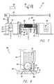
- a prior art shear inducing applicatoris shown generally by numeral 11 which is similar to the applicator disclosed in publication WO 00/51809.
- the prior art applicator 11has a doctor blade 13 in close proximity to shear inducing rollers 15 .
- shear stressis induced on the high viscosity build material 17 causing the material to flow. This allows the doctor blade 13 to sweep a uniform layer of build material 19 .
- the proper speed of rotation of the rollers 15 and the proper distance between the rollers 15 and the doctor blade 13are parameters that are critical in order to form a uniform layer by the shear inducing applicator. These parameters are dependent on the characteristics of the high viscosity material being coated.
- an alternative embodiment of a recoating applicator for applying the viscosity modified build material according to the present inventionis generally shown by numeral 60 .
- the viscosity modified build material 12is provided in a container 64 such that it is gravity fed to the dispensing area generally shown by numeral 62 .
- the recoating applicator 60includes a distribution roller 66 , a dispensing guide blade 68 , a skive 70 , and a doctor blade 18 .
- the surface tension of the viscosity modified build material 12 and gap between the roller 66 and blade 68are sufficiently matched such that the build material does not dispense when the distribution roller 66 is stationary.
- the skive 70prevents the dispensed build material from adhering to the roller 66 and returning to the container, and the doctor blade 18 provides the final sweep to form a uniform layer of viscosity modified build material 72 over a previous layer 74 .
- This gravity feed configurationis preferable over the previous embodiments particularly where the viscosity modified build material exhibits non-thixotropic like characteristics such as that of a liquid. This is because it has been found that gravity fed recoater systems can form thin uniform layers with liquids without causing undesirable ripples or waves in the layers as can occur when using smoothing members to skive the liquid over a surface.
- the transformation from the low viscosity state to the high viscosity stateat least be of an amount sufficient such that the build material in the layer becomes substantially self-supporting such as a gel in a thixotropic state.
- the transformationmay be of a greater amount, which may be the condition where the first viscosity value of the build material in the low viscosity state is at least less than about one-half of the second viscosity value of the build material in the high viscosity state.
- the transformationmay also be of a greater amount such as the condition where the transference of shear stress to the layer of build material in the high viscosity state when applying a new layer of build material in the low viscosity state is substantially prevented.
- any one of the embodiments discussed abovemay be adapted to apply uniform layers of different build material formulations in any SFF process to produce, for example, laminated three-dimensional objects.
- Such laminated objectsmay have different mechanical properties between the laminations that can be optimally oriented in the object to further improve the overall mechanical properties of the object.
Landscapes
- Engineering & Computer Science (AREA)
- Chemical & Material Sciences (AREA)
- Materials Engineering (AREA)
- Manufacturing & Machinery (AREA)
- Mechanical Engineering (AREA)
- Physics & Mathematics (AREA)
- Optics & Photonics (AREA)
- Ceramic Engineering (AREA)
- Civil Engineering (AREA)
- Composite Materials (AREA)
- Structural Engineering (AREA)
Abstract
Description
Claims (96)
Priority Applications (3)
| Application Number | Priority Date | Filing Date | Title |
|---|---|---|---|
| US10/052,506US6656410B2 (en) | 2001-06-22 | 2002-01-17 | Recoating system for using high viscosity build materials in solid freeform fabrication |
| EP02254253AEP1270185A1 (en) | 2001-06-22 | 2002-06-18 | Recoating system and method for solid freeform fabrication |
| JP2002182670AJP2003053847A (en) | 2001-06-22 | 2002-06-24 | Recoating system for using high viscosity build material in solid freeform fabrication |
Applications Claiming Priority (2)
| Application Number | Priority Date | Filing Date | Title |
|---|---|---|---|
| US09/887,174US20020195746A1 (en) | 2001-06-22 | 2001-06-22 | Recoating system for using high viscosity build materials in solid freeform fabrication |
| US10/052,506US6656410B2 (en) | 2001-06-22 | 2002-01-17 | Recoating system for using high viscosity build materials in solid freeform fabrication |
Related Parent Applications (1)
| Application Number | Title | Priority Date | Filing Date |
|---|---|---|---|
| US09/887,174Continuation-In-PartUS20020195746A1 (en) | 2001-06-22 | 2001-06-22 | Recoating system for using high viscosity build materials in solid freeform fabrication |
Publications (2)
| Publication Number | Publication Date |
|---|---|
| US20020195747A1 US20020195747A1 (en) | 2002-12-26 |
| US6656410B2true US6656410B2 (en) | 2003-12-02 |
Family
ID=26730689
Family Applications (1)
| Application Number | Title | Priority Date | Filing Date |
|---|---|---|---|
| US10/052,506Expired - Fee RelatedUS6656410B2 (en) | 2001-06-22 | 2002-01-17 | Recoating system for using high viscosity build materials in solid freeform fabrication |
Country Status (3)
| Country | Link |
|---|---|
| US (1) | US6656410B2 (en) |
| EP (1) | EP1270185A1 (en) |
| JP (1) | JP2003053847A (en) |
Cited By (42)
| Publication number | Priority date | Publication date | Assignee | Title |
|---|---|---|---|---|
| US20050112015A1 (en)* | 2003-11-21 | 2005-05-26 | Bampton Clifford C. | Laser sintered titanium alloy and direct metal fabrication method of making the same |
| US20060225834A1 (en)* | 2005-03-31 | 2006-10-12 | Board Of Regents, The University Of Texas System | Methods and systems for integrating fluid dispensing technology with stereolithography |
| US20060237880A1 (en)* | 2005-04-22 | 2006-10-26 | Board Of Regents, The University Of Texas System | Hydrogel constructs using stereolithography |
| US20070037509A1 (en)* | 2005-05-31 | 2007-02-15 | Bernd Renz | Method for the manufacture of a molding as well as a sensor unit for the application thereof |
| US20080190905A1 (en)* | 2005-07-01 | 2008-08-14 | Eos Gmbh Electro Optical Systems | Device For Producing a Three-Dimensional Object |
| US20080268351A1 (en)* | 2005-11-09 | 2008-10-30 | Stephan Landis | Method of Forming Supports Bearing Features, Such as Lithography Masks |
| US20090179355A1 (en)* | 2004-07-30 | 2009-07-16 | Ryan Wicker | Methods for multi-material stereolithography |
| US20090243156A1 (en)* | 2006-09-27 | 2009-10-01 | Jsr Corporation | Method of photofabrication |
| US8006407B2 (en)* | 2007-12-12 | 2011-08-30 | Richard Anderson | Drying system and method of using same |
| US20120133083A1 (en)* | 2009-08-03 | 2012-05-31 | Dws S.R.L. | Stereolithography Machine |
| US20150115490A1 (en)* | 2012-04-20 | 2015-04-30 | Eos Gmbh Electro Optical Systems | Method and Divice for Producing Components in a Beam Melting Installation |
| US20150158249A1 (en)* | 2013-12-10 | 2015-06-11 | Seiko Epson Corporation | Three dimensional mold object manufacturing apparatus, method for manufacturing three dimensional mold object, and three dimensional mold object |
| US9421715B2 (en) | 2009-10-13 | 2016-08-23 | Blueprinter Aps | Three-dimensional printer |
| US9573225B2 (en) | 2014-06-20 | 2017-02-21 | Velo3D, Inc. | Apparatuses, systems and methods for three-dimensional printing |
| US9662840B1 (en) | 2015-11-06 | 2017-05-30 | Velo3D, Inc. | Adept three-dimensional printing |
| US20170217091A1 (en)* | 2016-01-28 | 2017-08-03 | 3D Systems, Inc. | Methods and apparatus for 3d printed hydrogel materials |
| US20170270831A1 (en)* | 2016-03-17 | 2017-09-21 | Yoshihiro Norikane | Solid freeform fabrication object, internal organ model, and method of manufacturing the same |
| US20170341303A1 (en)* | 2014-08-29 | 2017-11-30 | Exone Gmbh | Coater arrangement for a 3D printer |
| US9890595B2 (en) | 2015-08-03 | 2018-02-13 | Baker Hughes, A Ge Company, Llc | Methods of forming and methods of repairing earth boring-tools |
| US9919360B2 (en) | 2016-02-18 | 2018-03-20 | Velo3D, Inc. | Accurate three-dimensional printing |
| US9962767B2 (en) | 2015-12-10 | 2018-05-08 | Velo3D, Inc. | Apparatuses for three-dimensional printing |
| US20180126649A1 (en) | 2016-11-07 | 2018-05-10 | Velo3D, Inc. | Gas flow in three-dimensional printing |
| US10059092B2 (en) | 2015-09-14 | 2018-08-28 | Baker Hughes, A Ge Company, Llc | Additive manufacturing of functionally gradient degradable tools |
| US10144176B1 (en) | 2018-01-15 | 2018-12-04 | Velo3D, Inc. | Three-dimensional printing systems and methods of their use |
| US10252336B2 (en) | 2016-06-29 | 2019-04-09 | Velo3D, Inc. | Three-dimensional printing and three-dimensional printers |
| US10272525B1 (en) | 2017-12-27 | 2019-04-30 | Velo3D, Inc. | Three-dimensional printing systems and methods of their use |
| US10315252B2 (en) | 2017-03-02 | 2019-06-11 | Velo3D, Inc. | Three-dimensional printing of three-dimensional objects |
| US10335855B2 (en) | 2015-09-14 | 2019-07-02 | Baker Hughes, A Ge Company, Llc | Additive manufacturing of functionally gradient degradable tools |
| US10363702B2 (en)* | 2017-02-21 | 2019-07-30 | Xyzprinting, Inc. | Three dimensional printing apparatus |
| US10386801B2 (en) | 2015-08-03 | 2019-08-20 | Baker Hughes, A Ge Company, Llc | Methods of forming and methods of repairing earth-boring tools |
| US10449696B2 (en) | 2017-03-28 | 2019-10-22 | Velo3D, Inc. | Material manipulation in three-dimensional printing |
| US10611092B2 (en) | 2017-01-05 | 2020-04-07 | Velo3D, Inc. | Optics in three-dimensional printing |
| WO2020092485A1 (en)* | 2018-10-31 | 2020-05-07 | Carbon, Inc. | Apparatuses for additively manufacturing three-dimensional objects |
| US11214010B2 (en) | 2019-07-11 | 2022-01-04 | Hewlett-Packard Development Company, L.P. | Roller control for a 3D printer |
| US11254049B2 (en)* | 2016-08-05 | 2022-02-22 | Shashin Kagaku Co., Ltd. | Optical fabricating apparatus and optical fabricating method |
| US11485699B2 (en) | 2016-07-06 | 2022-11-01 | Synthomer Adhesive Technologies Llc | (Meth)acrylic oligomers |
| US20230073194A1 (en)* | 2021-08-27 | 2023-03-09 | General Electric Company | Method of edge printing for use in additive manufacturing processes |
| US11691343B2 (en) | 2016-06-29 | 2023-07-04 | Velo3D, Inc. | Three-dimensional printing and three-dimensional printers |
| US20240075687A1 (en)* | 2020-12-28 | 2024-03-07 | Unijet Co., Ltd. | 3d printer cartridge and 3d printer |
| US11999110B2 (en) | 2019-07-26 | 2024-06-04 | Velo3D, Inc. | Quality assurance in formation of three-dimensional objects |
| US12053925B2 (en) | 2021-10-14 | 2024-08-06 | Align Technology, Inc. | Recoating system including multiple blades |
| US12070907B2 (en) | 2016-09-30 | 2024-08-27 | Velo3D | Three-dimensional objects and their formation |
Families Citing this family (151)
| Publication number | Priority date | Publication date | Assignee | Title |
|---|---|---|---|---|
| US20030091647A1 (en)* | 2001-11-15 | 2003-05-15 | Lewis Jennifer A. | Controlled dispersion of colloidal suspensions via nanoparticle additions |
| JP3724437B2 (en)* | 2002-02-25 | 2005-12-07 | 松下電工株式会社 | Manufacturing method and manufacturing apparatus for three-dimensional shaped object |
| US7168935B1 (en) | 2002-08-02 | 2007-01-30 | The United States Of America As Represented By The Administrator Of The National Aeronautics And Space Administration | Solid freeform fabrication apparatus and methods |
| US20040226620A1 (en) | 2002-09-26 | 2004-11-18 | Daniel Therriault | Microcapillary networks |
| US7141617B2 (en) | 2003-06-17 | 2006-11-28 | The Board Of Trustees Of The University Of Illinois | Directed assembly of three-dimensional structures with micron-scale features |
| US20060231982A1 (en) | 2003-07-23 | 2006-10-19 | Xiaorong You | Viscosity reducible radiation curable resin composition |
| DE102004022606A1 (en) | 2004-05-07 | 2005-12-15 | Envisiontec Gmbh | Method for producing a three-dimensional object with improved separation of hardened material layers from a building level |
| WO2005110722A1 (en) | 2004-05-10 | 2005-11-24 | Envisiontec Gmbh | Method for producing a three-dimensional object with resolution enhancement by means of pixel shift |
| DE102004022961B4 (en) | 2004-05-10 | 2008-11-20 | Envisiontec Gmbh | Method for producing a three-dimensional object with resolution improvement by means of pixel shift |
| US20060165547A1 (en)* | 2005-01-26 | 2006-07-27 | Honeywell International, Inc. | High strength rhenium alloys and high temperature components made from such alloys |
| DE102005016940B4 (en)* | 2005-04-12 | 2007-03-15 | Eos Gmbh Electro Optical Systems | Apparatus and method for applying layers of powdered material to a surface |
| RU2379158C2 (en)* | 2005-05-11 | 2010-01-20 | Аркам Аб | Method of powder plating |
| AT502110B1 (en)* | 2005-06-30 | 2008-09-15 | Univ Wien Tech | RADIATION-CURABLE COMPOSITION SOLUBLE IN ORGANIC SOLVENTS AND ITS USE IN RAPID PROTOTYPING PROCESS |
| DE102005035987A1 (en)* | 2005-07-28 | 2007-02-01 | "Stiftung Caesar" (Center Of Advanced European Studies And Research) | Process for the preparation of three-dimensional shaped bodies |
| DE102006019963B4 (en) | 2006-04-28 | 2023-12-07 | Envisiontec Gmbh | Device and method for producing a three-dimensional object by layer-by-layer solidifying a material that can be solidified under the influence of electromagnetic radiation using mask exposure |
| DE102006019964C5 (en) | 2006-04-28 | 2021-08-26 | Envisiontec Gmbh | Device and method for producing a three-dimensional object by means of mask exposure |
| US7636610B2 (en) | 2006-07-19 | 2009-12-22 | Envisiontec Gmbh | Method and device for producing a three-dimensional object, and computer and data carrier useful therefor |
| JP4917381B2 (en)* | 2006-08-09 | 2012-04-18 | 株式会社アスペクト | Powder sintering additive manufacturing apparatus and powder sintering additive manufacturing method |
| JP4857056B2 (en)* | 2006-09-12 | 2012-01-18 | 株式会社アスペクト | Powder sintering additive manufacturing apparatus and powder sintering additive manufacturing method |
| US20090250835A1 (en)* | 2006-09-27 | 2009-10-08 | Jsr Corporation | Method for manufacturing molding die and method for manufacturing molded product |
| US7892474B2 (en) | 2006-11-15 | 2011-02-22 | Envisiontec Gmbh | Continuous generative process for producing a three-dimensional object |
| DE102006055054A1 (en)* | 2006-11-22 | 2008-05-29 | Eos Gmbh Electro Optical Systems | Apparatus for layering a three-dimensional object |
| DE102006055052A1 (en)* | 2006-11-22 | 2008-05-29 | Eos Gmbh Electro Optical Systems | Apparatus for layering a three-dimensional object |
| DE102006055055A1 (en)* | 2006-11-22 | 2008-05-29 | Eos Gmbh Electro Optical Systems | Apparatus for layering a three-dimensional object |
| US8003039B2 (en) | 2007-01-17 | 2011-08-23 | 3D Systems, Inc. | Method for tilting solid image build platform for reducing air entrainment and for build release |
| JP4915660B2 (en)* | 2007-01-26 | 2012-04-11 | パナソニック株式会社 | Manufacturing method of three-dimensional shaped object |
| JP4925048B2 (en)* | 2007-01-26 | 2012-04-25 | パナソニック株式会社 | Manufacturing method of three-dimensional shaped object |
| US8475946B1 (en) | 2007-03-20 | 2013-07-02 | Bowling Green State University | Ceramic article and method of manufacture |
| US8568649B1 (en)* | 2007-03-20 | 2013-10-29 | Bowling Green State University | Three-dimensional printer, ceramic article and method of manufacture |
| US7956102B2 (en)* | 2007-04-09 | 2011-06-07 | The Board Of Trustees Of The University Of Illinois | Sol-gel inks |
| GB0712027D0 (en)* | 2007-06-21 | 2007-08-01 | Materials Solutions | Rotating build plate |
| ATE553910T1 (en) | 2007-07-04 | 2012-05-15 | Envisiontec Gmbh | METHOD AND DEVICE FOR PRODUCING A THREE-DIMENSIONAL OBJECT |
| EP2052693B2 (en) | 2007-10-26 | 2021-02-17 | Envisiontec GmbH | Process and freeform fabrication system for producing a three-dimensional object |
| US8992816B2 (en)* | 2008-01-03 | 2015-03-31 | Arcam Ab | Method and apparatus for producing three-dimensional objects |
| DE102008022946B4 (en) | 2008-05-09 | 2014-02-13 | Fit Fruth Innovative Technologien Gmbh | Apparatus and method for applying powders or pastes |
| KR100948284B1 (en) | 2008-08-27 | 2010-03-17 | 고등기술연구원연구조합 | High Viscosity Sample Feeder |
| US7922939B2 (en) | 2008-10-03 | 2011-04-12 | The Board Of Trustees Of The University Of Illinois | Metal nanoparticle inks |
| US8187500B2 (en) | 2008-10-17 | 2012-05-29 | The Board Of Trustees Of The University Of Illinois | Biphasic inks |
| US8048359B2 (en) | 2008-10-20 | 2011-11-01 | 3D Systems, Inc. | Compensation of actinic radiation intensity profiles for three-dimensional modelers |
| DE102008058177A1 (en)* | 2008-11-20 | 2010-06-24 | Eos Gmbh Electro Optical Systems | Method for identifying laser sintering powders |
| CN102470439B (en) | 2009-07-15 | 2016-03-02 | 阿卡姆股份公司 | Manufacture the method and apparatus of three-dimensional body |
| US8372330B2 (en) | 2009-10-19 | 2013-02-12 | Global Filtration Systems | Resin solidification substrate and assembly |
| DE102010004036A1 (en)* | 2010-01-05 | 2011-07-07 | EOS GmbH Electro Optical Systems, 82152 | Apparatus for generatively producing a three-dimensional object with continuous heat input |
| US8222908B2 (en)* | 2010-02-16 | 2012-07-17 | Stratasys, Inc. | Capacitive detector for use in extrusion-based digital manufacturing systems |
| DE102010049068A1 (en)* | 2010-10-20 | 2012-04-26 | Mtu Aero Engines Gmbh | Device for producing, repairing and / or replacing a component by means of an energy-beam solidifiable powder, and a method and a component produced according to the method |
| DE102011007957A1 (en) | 2011-01-05 | 2012-07-05 | Voxeljet Technology Gmbh | Device and method for constructing a layer body with at least one body limiting the construction field and adjustable in terms of its position |
| JP5588925B2 (en)* | 2011-05-23 | 2014-09-10 | パナソニック株式会社 | Manufacturing method of three-dimensional shaped object |
| JP2013075391A (en)* | 2011-09-29 | 2013-04-25 | Brother Industries Ltd | Apparatus and program for creating three dimensional molding data |
| US8691476B2 (en) | 2011-12-16 | 2014-04-08 | Taiwan Semiconductor Manufacturing Company, Ltd. | EUV mask and method for forming the same |
| EP2797730B2 (en) | 2011-12-28 | 2020-03-04 | Arcam Ab | Method and apparatus for detecting defects in freeform fabrication |
| US10189086B2 (en) | 2011-12-28 | 2019-01-29 | Arcam Ab | Method and apparatus for manufacturing porous three-dimensional articles |
| TWI472427B (en)* | 2012-01-20 | 2015-02-11 | 財團法人工業技術研究院 | Device and method for powder distribution and additive manufacturing method using the same |
| FR2990375B1 (en)* | 2012-05-11 | 2014-05-23 | Univ Lorraine | USE OF A COMPLEX ALUMINUM METAL ALLOY FOR STEREOLITHOGRAPHY |
| DE102012219534A1 (en)* | 2012-10-25 | 2014-04-30 | Tools And Technologies Gmbh | Apparatus for producing a shaped body in layers |
| DE112013006045T5 (en) | 2012-12-17 | 2015-09-17 | Arcam Ab | Additive manufacturing method and device |
| US9550207B2 (en) | 2013-04-18 | 2017-01-24 | Arcam Ab | Method and apparatus for additive manufacturing |
| US9676031B2 (en) | 2013-04-23 | 2017-06-13 | Arcam Ab | Method and apparatus for forming a three-dimensional article |
| US10150258B2 (en)* | 2013-07-29 | 2018-12-11 | Carnegie Mellon University | Additive manufacturing of embedded materials |
| US9969930B2 (en) | 2013-08-15 | 2018-05-15 | Halliburton Energy Services, Inc. | Additive fabrication of proppants |
| DE102013217422A1 (en)* | 2013-09-02 | 2015-03-05 | Carl Zeiss Industrielle Messtechnik Gmbh | Coordinate measuring machine and method for measuring and at least partially producing a workpiece |
| US9676032B2 (en) | 2013-09-20 | 2017-06-13 | Arcam Ab | Method for additive manufacturing |
| EP3057776B1 (en)* | 2013-10-17 | 2020-03-18 | Xjet Ltd. | Support ink for three dimensional (3d) printing |
| US11235409B2 (en)* | 2013-10-18 | 2022-02-01 | +Mfg, LLC | Method and apparatus for fabrication of articles by molten and semi-molten deposition |
| US10434572B2 (en) | 2013-12-19 | 2019-10-08 | Arcam Ab | Method for additive manufacturing |
| US9802253B2 (en) | 2013-12-16 | 2017-10-31 | Arcam Ab | Additive manufacturing of three-dimensional articles |
| US10130993B2 (en) | 2013-12-18 | 2018-11-20 | Arcam Ab | Additive manufacturing of three-dimensional articles |
| US9789563B2 (en) | 2013-12-20 | 2017-10-17 | Arcam Ab | Method for additive manufacturing |
| JP6273849B2 (en)* | 2014-01-15 | 2018-02-07 | セイコーエプソン株式会社 | Three-dimensional structure manufacturing method, three-dimensional structure manufacturing apparatus, and ink set |
| US9527244B2 (en)* | 2014-02-10 | 2016-12-27 | Global Filtration Systems | Apparatus and method for forming three-dimensional objects from solidifiable paste |
| US9789541B2 (en) | 2014-03-07 | 2017-10-17 | Arcam Ab | Method for additive manufacturing of three-dimensional articles |
| JP2015196267A (en)* | 2014-03-31 | 2015-11-09 | 株式会社東芝 | Method and apparatus for production of laminated molding and slurry |
| US20150283613A1 (en) | 2014-04-02 | 2015-10-08 | Arcam Ab | Method for fusing a workpiece |
| JP6379684B2 (en) | 2014-06-02 | 2018-08-29 | 株式会社リコー | 3D modeling equipment |
| CA2993343A1 (en)* | 2014-08-05 | 2016-02-11 | Laing O'rourke Australia Pty Limited | Apparatus for fabricating an object |
| US9310188B2 (en) | 2014-08-20 | 2016-04-12 | Arcam Ab | Energy beam deflection speed verification |
| DE102014222129A1 (en)* | 2014-10-29 | 2016-05-04 | Eos Gmbh Electro Optical Systems | Method, apparatus and coating module for producing a three-dimensional object |
| DE102014222302A1 (en)* | 2014-10-31 | 2016-05-04 | Siemens Aktiengesellschaft | Producing a component by selective laser melting |
| US10449692B2 (en) | 2014-12-08 | 2019-10-22 | Tethon Corporation | Three-dimensional (3D) printing |
| US10786865B2 (en) | 2014-12-15 | 2020-09-29 | Arcam Ab | Method for additive manufacturing |
| US9721755B2 (en) | 2015-01-21 | 2017-08-01 | Arcam Ab | Method and device for characterizing an electron beam |
| JP6515557B2 (en) | 2015-02-04 | 2019-05-22 | セイコーエプソン株式会社 | Member for manufacturing three-dimensional object, apparatus for manufacturing three-dimensional object, method for manufacturing three-dimensional object, and three-dimensional object |
| US11014161B2 (en) | 2015-04-21 | 2021-05-25 | Arcam Ab | Method for additive manufacturing |
| EP3288700B1 (en)* | 2015-04-30 | 2023-09-13 | The Exone Company | Powder recoater for three-dimensional printer |
| JP6751434B2 (en)* | 2015-07-13 | 2020-09-02 | マッシビット スリーディー プリンティング テクノロジーズ リミテッド | Support structure |
| KR20170010469A (en)* | 2015-07-20 | 2017-02-01 | 고려대학교 산학협력단 | 3-dimensional Printing Apparatus |
| DE102015010386B4 (en)* | 2015-08-08 | 2022-10-13 | Additive 3D Training Gmbh | Device for additive manufacturing of three-dimensional objects |
| NL2015381B1 (en)* | 2015-09-01 | 2017-03-20 | Stichting Energieonderzoek Centrum Nederland | Additive manufacturing method and apparatus. |
| WO2017044735A1 (en)* | 2015-09-10 | 2017-03-16 | Dow Corning Corporation | 3d printing method utilizing thermoplastic silicone composition |
| KR102145530B1 (en)* | 2015-09-14 | 2020-08-19 | 타이거 코팅스 게엠베하 운트 코. 카게 | Use of thermosetting polymeric powder composition |
| US10807187B2 (en) | 2015-09-24 | 2020-10-20 | Arcam Ab | X-ray calibration standard object |
| US10583483B2 (en) | 2015-10-15 | 2020-03-10 | Arcam Ab | Method and apparatus for producing a three-dimensional article |
| US10525531B2 (en) | 2015-11-17 | 2020-01-07 | Arcam Ab | Additive manufacturing of three-dimensional articles |
| US10610930B2 (en) | 2015-11-18 | 2020-04-07 | Arcam Ab | Additive manufacturing of three-dimensional articles |
| TWI582885B (en)* | 2015-12-30 | 2017-05-11 | 國立中央大學 | Platform structure for low temperature manufacturing tissue engineering bracket and method for manufacturing low temperature manufacturing tissue engineering bracket |
| US11247274B2 (en) | 2016-03-11 | 2022-02-15 | Arcam Ab | Method and apparatus for forming a three-dimensional article |
| BR112018015426A2 (en) | 2016-04-10 | 2018-12-18 | Hewlett Packard Development Co | distribution of powdered building material for additive manufacturing |
| US10889057B2 (en)* | 2016-05-12 | 2021-01-12 | Hewlett-Packard Development Company, L.P. | Material sets |
| US11325191B2 (en) | 2016-05-24 | 2022-05-10 | Arcam Ab | Method for additive manufacturing |
| JP6932996B2 (en)* | 2016-05-24 | 2021-09-08 | 株式会社リコー | Manufacturing method and manufacturing equipment for three-dimensional objects |
| US10549348B2 (en) | 2016-05-24 | 2020-02-04 | Arcam Ab | Method for additive manufacturing |
| US10525547B2 (en) | 2016-06-01 | 2020-01-07 | Arcam Ab | Additive manufacturing of three-dimensional articles |
| DE102016211952A1 (en) | 2016-06-30 | 2018-01-04 | Eos Gmbh Electro Optical Systems | Coating unit, coating method, apparatus and method for generatively producing a three-dimensional object |
| BR112018077517A2 (en) | 2016-06-30 | 2019-04-02 | 3M Innovative Properties Company | printable compositions including highly viscous components and methods for creating 3d articles from them |
| FR3056425B1 (en) | 2016-09-29 | 2018-11-23 | Safran Aircraft Engines | DEVICE FOR MANUFACTURING ANNULAR PIECES BY SELECTIVE FUSION OF POWDER COMPRISING A POWDER SCRAPER |
| CN109906140A (en) | 2016-10-19 | 2019-06-18 | 株式会社大赛璐 | Composition for three-dimensional modeling, method for producing three-dimensional modeling object, and three-dimensional modeling object |
| US10792757B2 (en) | 2016-10-25 | 2020-10-06 | Arcam Ab | Method and apparatus for additive manufacturing |
| US10987752B2 (en) | 2016-12-21 | 2021-04-27 | Arcam Ab | Additive manufacturing of three-dimensional articles |
| US10569364B2 (en) | 2017-01-06 | 2020-02-25 | General Electric Company | Systems and methods for additive manufacturing recoating |
| US10737479B2 (en) | 2017-01-12 | 2020-08-11 | Global Filtration Systems | Method of making three-dimensional objects using both continuous and discontinuous solidification |
| CN108407287B (en)* | 2017-02-09 | 2020-03-31 | 三纬国际立体列印科技股份有限公司 | 3D printing device |
| US20180304358A1 (en)* | 2017-04-21 | 2018-10-25 | Desktop Metal, Inc. | Powder dispensing in binder jetting for additive manufacturing |
| US11059123B2 (en) | 2017-04-28 | 2021-07-13 | Arcam Ab | Additive manufacturing of three-dimensional articles |
| US11292062B2 (en) | 2017-05-30 | 2022-04-05 | Arcam Ab | Method and device for producing three-dimensional objects |
| US11185926B2 (en) | 2017-09-29 | 2021-11-30 | Arcam Ab | Method and apparatus for additive manufacturing |
| US10529070B2 (en) | 2017-11-10 | 2020-01-07 | Arcam Ab | Method and apparatus for detecting electron beam source filament wear |
| US10307823B1 (en)* | 2017-11-13 | 2019-06-04 | General Electric Company | Methods and systems for repairing powder containment structures |
| EP3486071A1 (en)* | 2017-11-21 | 2019-05-22 | CL Schutzrechtsverwaltungs GmbH | Apparatus for additively manufacturing of three-dimensional objects |
| US10821721B2 (en) | 2017-11-27 | 2020-11-03 | Arcam Ab | Method for analysing a build layer |
| US11072117B2 (en) | 2017-11-27 | 2021-07-27 | Arcam Ab | Platform device |
| WO2019118946A2 (en)* | 2017-12-15 | 2019-06-20 | Chartrain Nicholas | High-temperature stereolithography apparatus and methods of use thereof |
| US11517975B2 (en) | 2017-12-22 | 2022-12-06 | Arcam Ab | Enhanced electron beam generation |
| US12350754B2 (en) | 2017-12-22 | 2025-07-08 | Arcam Ab | Electron beam source and the use of the same |
| US10967459B2 (en)* | 2018-02-05 | 2021-04-06 | General Electric Company | Customizable powder bed containment systems for use with direct metal laser melting systems |
| US10800101B2 (en) | 2018-02-27 | 2020-10-13 | Arcam Ab | Compact build tank for an additive manufacturing apparatus |
| US11267051B2 (en) | 2018-02-27 | 2022-03-08 | Arcam Ab | Build tank for an additive manufacturing apparatus |
| CN112074395A (en)* | 2018-03-02 | 2020-12-11 | 福姆实验室公司 | Latent curing resins and related methods |
| US11400519B2 (en) | 2018-03-29 | 2022-08-02 | Arcam Ab | Method and device for distributing powder material |
| WO2019206903A1 (en) | 2018-04-23 | 2019-10-31 | Carl Zeiss Industrial Metrology, Llc | Method and arrangement for producing a workpiece by using adaptive closed-loop control of additive manufacturing techniques |
| WO2019213597A1 (en)* | 2018-05-04 | 2019-11-07 | Addleap Ab | A support edifice for three-dimensional printing |
| JP7159777B2 (en)* | 2018-10-15 | 2022-10-25 | セイコーエプソン株式会社 | Manufacturing method of three-dimensional model |
| US20230373158A1 (en)* | 2019-03-12 | 2023-11-23 | Trio Labs, Inc. | Method and apparatus for digital fabrication and structure made using the same |
| EP3972757A1 (en) | 2019-05-23 | 2022-03-30 | General Electric Company | Additive manufacturing apparatuses and methods |
| US12208583B2 (en) | 2019-05-23 | 2025-01-28 | General Electric Company | Wiper arrays for use in additive manufacturing apparatuses |
| WO2020237142A1 (en) | 2019-05-23 | 2020-11-26 | General Electric Company | Additive manufacturing recoat assemblies including a vacuum and methods for using the same |
| US12076918B2 (en) | 2019-05-23 | 2024-09-03 | General Electric Company | Additive manufacturing apparatuses and methods for using the same |
| CN114206591A (en) | 2019-05-23 | 2022-03-18 | 通用电气公司 | Cleaning system for additive manufacturing apparatus and method of using same |
| US12172370B2 (en) | 2019-05-23 | 2024-12-24 | General Electric Company | Recoat assemblies for additive manufacturing systems and methods for using the same |
| EP3972760A1 (en) | 2019-05-23 | 2022-03-30 | General Electric Company | Fluid management and circulation systems for use in additive manufacturing apparatuses |
| EP3972847A1 (en) | 2019-05-23 | 2022-03-30 | General Electric Company | Printing assemblies and methods for using the same |
| EP3972761A2 (en) | 2019-05-23 | 2022-03-30 | General Electric Company | Cleaning fluids for use in additive manufacturing apparatuses and methods for monitoring status and performance of the same |
| US12059841B2 (en) | 2019-05-23 | 2024-08-13 | General Electric Company | Additive manufacturing recoat assemblies including sensors and methods for using the same |
| WO2020237163A1 (en)* | 2019-05-23 | 2020-11-26 | General Electric Company | Build receptacles for additive manufacturing apparatuses and methods for using the same |
| WO2020256825A1 (en)* | 2019-06-18 | 2020-12-24 | Carbon, Inc. | Additive manufacturing method and apparatus for the production of dental crowns and other objects |
| FR3098438B1 (en)* | 2019-07-08 | 2021-06-11 | S A S 3Dceram Sinto | PASTE LAYER APPLICATION DEVICE FOR AN APPARATUS FOR MANUFACTURING CERAMIC PARTS BY STEREOLITHOGRAPHY |
| CN110421841A (en)* | 2019-09-05 | 2019-11-08 | 上海梓域材料科技有限公司 | One kind is exempted to support photosensitive 3D printer |
| WO2021095036A1 (en)* | 2019-11-15 | 2021-05-20 | Tritone Technologies Ltd. | Machine for additive manufacture incorporating molded layers |
| CN114099769A (en)* | 2020-09-01 | 2022-03-01 | 苏州中瑞智创三维科技股份有限公司 | A material and method for 3D printing dental all-ceramic restorations using viscoelastic paste |
| EP4208328A4 (en)* | 2020-09-04 | 2024-10-30 | Vulcanforms Inc. | DEFECT MITIGATION FOR COVERING SYSTEMS FOR ADDITIVE MANUFACTURING |
| KR102483586B1 (en)* | 2021-07-14 | 2023-01-02 | 주식회사 쓰리디컨트롤즈 | 3d printer containing a vat for handling high viscosity resin |
| GB2611314A (en)* | 2021-09-29 | 2023-04-05 | Additive Manufacturing Tech Ltd | Additive manufacturing method and apparatus |
| TWI867368B (en)* | 2021-12-06 | 2024-12-21 | 品瓷科技股份有限公司 | Slurry 3D light-curing molding equipment |
Citations (14)
| Publication number | Priority date | Publication date | Assignee | Title |
|---|---|---|---|---|
| US3264103A (en) | 1962-06-27 | 1966-08-02 | Du Pont | Photopolymerizable relief printing plates developed by dry thermal transfer |
| US3395014A (en) | 1963-06-07 | 1968-07-30 | Du Pont | Preparation of printing plates by heat plus a pressure gradient |
| US5096530A (en) | 1990-06-28 | 1992-03-17 | 3D Systems, Inc. | Resin film recoating method and apparatus |
| US5234636A (en) | 1989-09-29 | 1993-08-10 | 3D Systems, Inc. | Methods of coating stereolithographic parts |
| US5358673A (en) | 1990-02-15 | 1994-10-25 | 3D Systems, Inc. | Applicator device and method for dispensing a liquid medium in a laser modeling machine |
| US5447822A (en) | 1989-09-28 | 1995-09-05 | 3D Systems, Inc. | Apparatus and related method for forming a substantially flat stereolithographic working surface |
| US5474719A (en) | 1991-02-14 | 1995-12-12 | E. I. Du Pont De Nemours And Company | Method for forming solid objects utilizing viscosity reducible compositions |
| US5626919A (en) | 1990-03-01 | 1997-05-06 | E. I. Du Pont De Nemours And Company | Solid imaging apparatus and method with coating station |
| US5651934A (en) | 1988-09-26 | 1997-07-29 | 3D Systems, Inc. | Recoating of stereolithographic layers |
| US5688464A (en) | 1990-03-19 | 1997-11-18 | 3D Systems, Inc. | Vibrationally enhanced stereolithographic recoating |
| US5922364A (en) | 1997-03-03 | 1999-07-13 | Young, Jr.; Albert C. | Stereolithography layering control system |
| US6020508A (en) | 1997-05-16 | 2000-02-01 | National Starch And Chemical Investment Holding Corporation | Radiation- or thermally-initiated cationically-curable epoxide compounds and compositions made from those compounds |
| WO2000051809A1 (en) | 1999-03-01 | 2000-09-08 | Optoform Sarl Procedes De Prototypage Rapide | Fast three-dimensional modelling method and device, and three-dimensional part obtained by fast three-dimensional modelling |
| US6180188B1 (en) | 1997-02-10 | 2001-01-30 | Commissariat A L'energie Atomique | Method for preparing a multilayer optical material with crosslinking-densifying by ultraviolet radiation |
Family Cites Families (5)
| Publication number | Priority date | Publication date | Assignee | Title |
|---|---|---|---|---|
| JP2737195B2 (en)* | 1988-12-28 | 1998-04-08 | ソニー株式会社 | 3D shape forming device |
| JPH0798363B2 (en)* | 1993-05-06 | 1995-10-25 | スリーデイー、システムズ、インコーポレーテッド | Method and apparatus for creating three-dimensional objects |
| JPH09241311A (en)* | 1996-03-13 | 1997-09-16 | Olympus Optical Co Ltd | Powder-containing photocurable flowable resin composition |
| JP4307636B2 (en)* | 1999-07-13 | 2009-08-05 | ナブテスコ株式会社 | Photocurable resin composition for optical three-dimensional modeling |
| JP2001096629A (en)* | 1999-09-29 | 2001-04-10 | Sanyo Electric Co Ltd | Stereolithography |
- 2002
- 2002-01-17USUS10/052,506patent/US6656410B2/ennot_activeExpired - Fee Related
- 2002-06-18EPEP02254253Apatent/EP1270185A1/ennot_activeWithdrawn
- 2002-06-24JPJP2002182670Apatent/JP2003053847A/enactivePending
Patent Citations (17)
| Publication number | Priority date | Publication date | Assignee | Title |
|---|---|---|---|---|
| US3264103A (en) | 1962-06-27 | 1966-08-02 | Du Pont | Photopolymerizable relief printing plates developed by dry thermal transfer |
| US3395014A (en) | 1963-06-07 | 1968-07-30 | Du Pont | Preparation of printing plates by heat plus a pressure gradient |
| US5651934A (en) | 1988-09-26 | 1997-07-29 | 3D Systems, Inc. | Recoating of stereolithographic layers |
| US6048487A (en) | 1988-09-26 | 2000-04-11 | 3D Systems, Inc. | Recoating stereolithographic layers |
| US5891382A (en) | 1988-09-26 | 1999-04-06 | 3D System, Inc. | Recoating of stereolithographic layers |
| US5447822A (en) | 1989-09-28 | 1995-09-05 | 3D Systems, Inc. | Apparatus and related method for forming a substantially flat stereolithographic working surface |
| US5234636A (en) | 1989-09-29 | 1993-08-10 | 3D Systems, Inc. | Methods of coating stereolithographic parts |
| US5358673A (en) | 1990-02-15 | 1994-10-25 | 3D Systems, Inc. | Applicator device and method for dispensing a liquid medium in a laser modeling machine |
| US5626919A (en) | 1990-03-01 | 1997-05-06 | E. I. Du Pont De Nemours And Company | Solid imaging apparatus and method with coating station |
| US6174156B1 (en) | 1990-03-01 | 2001-01-16 | Dsm N.V. | Solid imaging apparatus and method with coating station |
| US5688464A (en) | 1990-03-19 | 1997-11-18 | 3D Systems, Inc. | Vibrationally enhanced stereolithographic recoating |
| US5096530A (en) | 1990-06-28 | 1992-03-17 | 3D Systems, Inc. | Resin film recoating method and apparatus |
| US5474719A (en) | 1991-02-14 | 1995-12-12 | E. I. Du Pont De Nemours And Company | Method for forming solid objects utilizing viscosity reducible compositions |
| US6180188B1 (en) | 1997-02-10 | 2001-01-30 | Commissariat A L'energie Atomique | Method for preparing a multilayer optical material with crosslinking-densifying by ultraviolet radiation |
| US5922364A (en) | 1997-03-03 | 1999-07-13 | Young, Jr.; Albert C. | Stereolithography layering control system |
| US6020508A (en) | 1997-05-16 | 2000-02-01 | National Starch And Chemical Investment Holding Corporation | Radiation- or thermally-initiated cationically-curable epoxide compounds and compositions made from those compounds |
| WO2000051809A1 (en) | 1999-03-01 | 2000-09-08 | Optoform Sarl Procedes De Prototypage Rapide | Fast three-dimensional modelling method and device, and three-dimensional part obtained by fast three-dimensional modelling |
Cited By (90)
| Publication number | Priority date | Publication date | Assignee | Title |
|---|---|---|---|---|
| US20050112015A1 (en)* | 2003-11-21 | 2005-05-26 | Bampton Clifford C. | Laser sintered titanium alloy and direct metal fabrication method of making the same |
| US7540996B2 (en)* | 2003-11-21 | 2009-06-02 | The Boeing Company | Laser sintered titanium alloy and direct metal fabrication method of making the same |
| US7959847B2 (en) | 2004-07-30 | 2011-06-14 | The Board Of Regents Of The University Of Texas System | Methods for multi-material stereolithography |
| US20090179355A1 (en)* | 2004-07-30 | 2009-07-16 | Ryan Wicker | Methods for multi-material stereolithography |
| US7658603B2 (en) | 2005-03-31 | 2010-02-09 | Board Of Regents, The University Of Texas System | Methods and systems for integrating fluid dispensing technology with stereolithography |
| US8252223B2 (en)* | 2005-03-31 | 2012-08-28 | Board Of Regents, The University Of Texas System | Methods and systems for integrating fluid dispensing technology with stereolithography |
| US20100127433A1 (en)* | 2005-03-31 | 2010-05-27 | Francisco Medina | Methods and Systems for Integrating Fluid Dispensing Technology With Stereolithography |
| US20060225834A1 (en)* | 2005-03-31 | 2006-10-12 | Board Of Regents, The University Of Texas System | Methods and systems for integrating fluid dispensing technology with stereolithography |
| US20060237880A1 (en)* | 2005-04-22 | 2006-10-26 | Board Of Regents, The University Of Texas System | Hydrogel constructs using stereolithography |
| US8197743B2 (en) | 2005-04-22 | 2012-06-12 | Keck Graduate Institute | Hydrogel constructs using stereolithography |
| US7780897B2 (en) | 2005-04-22 | 2010-08-24 | Board Of Regents, The University Of Texas System | Hydrogel constructs using stereolithography |
| US20110059292A1 (en)* | 2005-04-22 | 2011-03-10 | Ryan Wicker | Hydrogel constructs using stereolithography |
| US20070037509A1 (en)* | 2005-05-31 | 2007-02-15 | Bernd Renz | Method for the manufacture of a molding as well as a sensor unit for the application thereof |
| US7847212B2 (en)* | 2005-05-31 | 2010-12-07 | Trumpf Werkzeugmaschinen Gmbh & Co. Kg | Method for the manufacture of a molding as well as a sensor unit for the application thereof |
| US20080190905A1 (en)* | 2005-07-01 | 2008-08-14 | Eos Gmbh Electro Optical Systems | Device For Producing a Three-Dimensional Object |
| US20080268351A1 (en)* | 2005-11-09 | 2008-10-30 | Stephan Landis | Method of Forming Supports Bearing Features, Such as Lithography Masks |
| US20090243156A1 (en)* | 2006-09-27 | 2009-10-01 | Jsr Corporation | Method of photofabrication |
| US8006407B2 (en)* | 2007-12-12 | 2011-08-30 | Richard Anderson | Drying system and method of using same |
| US20120133083A1 (en)* | 2009-08-03 | 2012-05-31 | Dws S.R.L. | Stereolithography Machine |
| US8945456B2 (en)* | 2009-08-03 | 2015-02-03 | Dws S.R.L. | Stereolithography machine |
| US9421715B2 (en) | 2009-10-13 | 2016-08-23 | Blueprinter Aps | Three-dimensional printer |
| US10232603B2 (en) | 2009-10-13 | 2019-03-19 | Hewlett-Packard Development Company, L.P. | Three-dimensional printer |
| US20150115490A1 (en)* | 2012-04-20 | 2015-04-30 | Eos Gmbh Electro Optical Systems | Method and Divice for Producing Components in a Beam Melting Installation |
| US10035304B2 (en)* | 2012-04-20 | 2018-07-31 | Eos Gmbh Electro Optical Systems | Method and device for producing components in a beam melting installation |
| US10137637B2 (en)* | 2013-12-10 | 2018-11-27 | Seiko Epson Corporation | Three dimensional mold object manufacturing apparatus, method for manufacturing three dimensional mold object, and three dimensional mold object |
| US20150158249A1 (en)* | 2013-12-10 | 2015-06-11 | Seiko Epson Corporation | Three dimensional mold object manufacturing apparatus, method for manufacturing three dimensional mold object, and three dimensional mold object |
| US20190054704A1 (en)* | 2013-12-10 | 2019-02-21 | Seiko Epson Corporation | Three dimensional mold object manufacturing apparatus, method for manufacturing three dimensional mold object, and three dimensional mold object |
| US10759119B2 (en)* | 2013-12-10 | 2020-09-01 | Seiko Epson Corporation | Three dimensional mold object manufacturing apparatus, method for manufacturing three dimensional mold object, and three dimensional mold object |
| US10195693B2 (en) | 2014-06-20 | 2019-02-05 | Vel03D, Inc. | Apparatuses, systems and methods for three-dimensional printing |
| US9586290B2 (en) | 2014-06-20 | 2017-03-07 | Velo3D, Inc. | Systems for three-dimensional printing |
| US9573225B2 (en) | 2014-06-20 | 2017-02-21 | Velo3D, Inc. | Apparatuses, systems and methods for three-dimensional printing |
| US9821411B2 (en) | 2014-06-20 | 2017-11-21 | Velo3D, Inc. | Apparatuses, systems and methods for three-dimensional printing |
| US10493564B2 (en) | 2014-06-20 | 2019-12-03 | Velo3D, Inc. | Apparatuses, systems and methods for three-dimensional printing |
| US10507549B2 (en) | 2014-06-20 | 2019-12-17 | Velo3D, Inc. | Apparatuses, systems and methods for three-dimensional printing |
| US11524454B2 (en)* | 2014-08-29 | 2022-12-13 | Exone Gmbh | Coater arrangement for a 3D printer |
| US20170341303A1 (en)* | 2014-08-29 | 2017-11-30 | Exone Gmbh | Coater arrangement for a 3D printer |
| US10386801B2 (en) | 2015-08-03 | 2019-08-20 | Baker Hughes, A Ge Company, Llc | Methods of forming and methods of repairing earth-boring tools |
| US9890595B2 (en) | 2015-08-03 | 2018-02-13 | Baker Hughes, A Ge Company, Llc | Methods of forming and methods of repairing earth boring-tools |
| US10059092B2 (en) | 2015-09-14 | 2018-08-28 | Baker Hughes, A Ge Company, Llc | Additive manufacturing of functionally gradient degradable tools |
| US10335855B2 (en) | 2015-09-14 | 2019-07-02 | Baker Hughes, A Ge Company, Llc | Additive manufacturing of functionally gradient degradable tools |
| US10807355B2 (en) | 2015-09-14 | 2020-10-20 | Baker Hughes, A Ge Company, Llc | Additive manufacturing of functionally gradient degradable tools |
| US10357957B2 (en) | 2015-11-06 | 2019-07-23 | Velo3D, Inc. | Adept three-dimensional printing |
| US10065270B2 (en) | 2015-11-06 | 2018-09-04 | Velo3D, Inc. | Three-dimensional printing in real time |
| US9676145B2 (en) | 2015-11-06 | 2017-06-13 | Velo3D, Inc. | Adept three-dimensional printing |
| US9662840B1 (en) | 2015-11-06 | 2017-05-30 | Velo3D, Inc. | Adept three-dimensional printing |
| US10183330B2 (en) | 2015-12-10 | 2019-01-22 | Vel03D, Inc. | Skillful three-dimensional printing |
| US10286603B2 (en) | 2015-12-10 | 2019-05-14 | Velo3D, Inc. | Skillful three-dimensional printing |
| US10207454B2 (en) | 2015-12-10 | 2019-02-19 | Velo3D, Inc. | Systems for three-dimensional printing |
| US10688722B2 (en) | 2015-12-10 | 2020-06-23 | Velo3D, Inc. | Skillful three-dimensional printing |
| US9962767B2 (en) | 2015-12-10 | 2018-05-08 | Velo3D, Inc. | Apparatuses for three-dimensional printing |
| US10058920B2 (en) | 2015-12-10 | 2018-08-28 | Velo3D, Inc. | Skillful three-dimensional printing |
| US10071422B2 (en) | 2015-12-10 | 2018-09-11 | Velo3D, Inc. | Skillful three-dimensional printing |
| US20170217091A1 (en)* | 2016-01-28 | 2017-08-03 | 3D Systems, Inc. | Methods and apparatus for 3d printed hydrogel materials |
| US11305480B2 (en)* | 2016-01-28 | 2022-04-19 | 3D Systems, Inc. | Methods and apparatus for 3D printed hydrogel materials |
| US9931697B2 (en) | 2016-02-18 | 2018-04-03 | Velo3D, Inc. | Accurate three-dimensional printing |
| US9919360B2 (en) | 2016-02-18 | 2018-03-20 | Velo3D, Inc. | Accurate three-dimensional printing |
| US10434573B2 (en) | 2016-02-18 | 2019-10-08 | Velo3D, Inc. | Accurate three-dimensional printing |
| US10252335B2 (en) | 2016-02-18 | 2019-04-09 | Vel03D, Inc. | Accurate three-dimensional printing |
| US20170270831A1 (en)* | 2016-03-17 | 2017-09-21 | Yoshihiro Norikane | Solid freeform fabrication object, internal organ model, and method of manufacturing the same |
| US10854113B2 (en)* | 2016-03-17 | 2020-12-01 | Ricoh Company, Ltd. | Solid freeform fabrication object, internal organ model, and method of manufacturing the same |
| US10259044B2 (en) | 2016-06-29 | 2019-04-16 | Velo3D, Inc. | Three-dimensional printing and three-dimensional printers |
| US10252336B2 (en) | 2016-06-29 | 2019-04-09 | Velo3D, Inc. | Three-dimensional printing and three-dimensional printers |
| US11691343B2 (en) | 2016-06-29 | 2023-07-04 | Velo3D, Inc. | Three-dimensional printing and three-dimensional printers |
| US10286452B2 (en) | 2016-06-29 | 2019-05-14 | Velo3D, Inc. | Three-dimensional printing and three-dimensional printers |
| US11485699B2 (en) | 2016-07-06 | 2022-11-01 | Synthomer Adhesive Technologies Llc | (Meth)acrylic oligomers |
| US11254049B2 (en)* | 2016-08-05 | 2022-02-22 | Shashin Kagaku Co., Ltd. | Optical fabricating apparatus and optical fabricating method |
| US12070907B2 (en) | 2016-09-30 | 2024-08-27 | Velo3D | Three-dimensional objects and their formation |
| US20180126649A1 (en) | 2016-11-07 | 2018-05-10 | Velo3D, Inc. | Gas flow in three-dimensional printing |
| US10661341B2 (en) | 2016-11-07 | 2020-05-26 | Velo3D, Inc. | Gas flow in three-dimensional printing |
| US10611092B2 (en) | 2017-01-05 | 2020-04-07 | Velo3D, Inc. | Optics in three-dimensional printing |
| US10363702B2 (en)* | 2017-02-21 | 2019-07-30 | Xyzprinting, Inc. | Three dimensional printing apparatus |
| US10442003B2 (en) | 2017-03-02 | 2019-10-15 | Velo3D, Inc. | Three-dimensional printing of three-dimensional objects |
| US10888925B2 (en) | 2017-03-02 | 2021-01-12 | Velo3D, Inc. | Three-dimensional printing of three-dimensional objects |
| US10369629B2 (en) | 2017-03-02 | 2019-08-06 | Veo3D, Inc. | Three-dimensional printing of three-dimensional objects |
| US10357829B2 (en) | 2017-03-02 | 2019-07-23 | Velo3D, Inc. | Three-dimensional printing of three-dimensional objects |
| US10315252B2 (en) | 2017-03-02 | 2019-06-11 | Velo3D, Inc. | Three-dimensional printing of three-dimensional objects |
| US10449696B2 (en) | 2017-03-28 | 2019-10-22 | Velo3D, Inc. | Material manipulation in three-dimensional printing |
| US10272525B1 (en) | 2017-12-27 | 2019-04-30 | Velo3D, Inc. | Three-dimensional printing systems and methods of their use |
| US10144176B1 (en) | 2018-01-15 | 2018-12-04 | Velo3D, Inc. | Three-dimensional printing systems and methods of their use |
| WO2020092485A1 (en)* | 2018-10-31 | 2020-05-07 | Carbon, Inc. | Apparatuses for additively manufacturing three-dimensional objects |
| US11192302B2 (en) | 2018-10-31 | 2021-12-07 | Carbon, Inc. | Apparatuses for additively manufacturing three-dimensional objects |
| US11654625B2 (en) | 2018-10-31 | 2023-05-23 | Carbon, Inc. | Apparatuses for additively manufacturing three-dimensional objects |
| US11214010B2 (en) | 2019-07-11 | 2022-01-04 | Hewlett-Packard Development Company, L.P. | Roller control for a 3D printer |
| US11999110B2 (en) | 2019-07-26 | 2024-06-04 | Velo3D, Inc. | Quality assurance in formation of three-dimensional objects |
| US20240075687A1 (en)* | 2020-12-28 | 2024-03-07 | Unijet Co., Ltd. | 3d printer cartridge and 3d printer |
| US11919233B2 (en)* | 2021-08-27 | 2024-03-05 | General Electric Company | Method of edge printing for use in additive manufacturing processes |
| US20230073194A1 (en)* | 2021-08-27 | 2023-03-09 | General Electric Company | Method of edge printing for use in additive manufacturing processes |
| US12053925B2 (en) | 2021-10-14 | 2024-08-06 | Align Technology, Inc. | Recoating system including multiple blades |
| US12208577B2 (en) | 2021-10-14 | 2025-01-28 | Align Technology, Inc. | Recoating system with reduced resin evaporation |
| US12343938B2 (en) | 2021-10-14 | 2025-07-01 | Align Technology | Recoating system including moving blade |
Also Published As
| Publication number | Publication date |
|---|---|
| US20020195747A1 (en) | 2002-12-26 |
| EP1270185A1 (en) | 2003-01-02 |
| JP2003053847A (en) | 2003-02-26 |
Similar Documents
| Publication | Publication Date | Title |
|---|---|---|
| US6656410B2 (en) | Recoating system for using high viscosity build materials in solid freeform fabrication | |
| US20020195746A1 (en) | Recoating system for using high viscosity build materials in solid freeform fabrication | |
| CN113795370B (en) | Method and apparatus for digitally fabricating objects employing actuated micropixel and dynamic density control | |
| US5980813A (en) | Rapid prototyping using multiple materials | |
| AU2018262560B2 (en) | Molding method and apparatus, particularly applicable to metal and/or ceramics | |
| US10137636B2 (en) | Three-dimensional modelling and/or manufacturing apparatus, and related processes | |
| EP3659728B1 (en) | Method for layer-wise additive manufacturing of a shaped body | |
| US7329379B2 (en) | Method for solid freeform fabrication of a three-dimensional object | |
| US20070063366A1 (en) | Removal of fluid by-product from a solid deposition modeling process | |
| EP1512519A2 (en) | A method and a system for solid freeform fabrication using non-reactive powder | |
| US20050200039A1 (en) | Materials and methods for freeform fabrication of solid three-dimensional objects using fusible, water-containing support materials | |
| US20050074596A1 (en) | Method and system for using porous structures in solid freeform fabrication | |
| CN112060573A (en) | Method and apparatus for producing three-dimensional models using an adhesive system | |
| JP2017524579A (en) | Multi-material 3D printer | |
| JP2015205485A (en) | Sintering shaping method, liquid binder, and sintered shaped article | |
| AU2019444497B2 (en) | Formulations for additive manufacturing of three-dimensional objects containing sinterable materials | |
| JPH02130132A (en) | Manufacture of optical shaped article | |
| US11618212B2 (en) | Additive fabrication of sinterable metallic parts via application of directed energy | |
| WO2016008876A1 (en) | Method and arrangement for the additive manufacture of components | |
| US20250262663A1 (en) | Organic formulations for additive manufacturing of three-dimensional objects containing sinterable materials | |
| Venuvinod et al. | Selective laser sintering (SLS) | |
| Kuang et al. | Polymers for Additive Manufacturing | |
| Montoya Ashton | HIGH SPEED CONTINUOUS ADDITIVE MANUFACTURING AT THE LIQUID-LIQUID INTERFACE |
Legal Events
| Date | Code | Title | Description |
|---|---|---|---|
| AS | Assignment | Owner name:3D SYSTEMS, INC., CALIFORNIA Free format text:ASSIGNMENT OF ASSIGNORS INTEREST;ASSIGNORS:HULL, CHARLES W.;NEWELL, KENNETH J.;REEL/FRAME:012529/0753 Effective date:20020117 | |
| AS | Assignment | Owner name:BANK ONE, NA, AS ADMINISTRATIVE AGENT, ILLINOIS Free format text:SECURITY AGREEMENT;ASSIGNOR:XEROX CORPORATION;REEL/FRAME:013111/0001 Effective date:20020621 Owner name:BANK ONE, NA, AS ADMINISTRATIVE AGENT,ILLINOIS Free format text:SECURITY AGREEMENT;ASSIGNOR:XEROX CORPORATION;REEL/FRAME:013111/0001 Effective date:20020621 | |
| FPAY | Fee payment | Year of fee payment:4 | |
| REMI | Maintenance fee reminder mailed | ||
| LAPS | Lapse for failure to pay maintenance fees | ||
| STCH | Information on status: patent discontinuation | Free format text:PATENT EXPIRED DUE TO NONPAYMENT OF MAINTENANCE FEES UNDER 37 CFR 1.362 | |
| FP | Lapsed due to failure to pay maintenance fee | Effective date:20111202 | |
| AS | Assignment | Owner name:XEROX CORPORATION, CONNECTICUT Free format text:RELEASE BY SECURED PARTY;ASSIGNOR:JPMORGAN CHASE BANK, N.A. AS SUCCESSOR-IN-INTEREST ADMINISTRATIVE AGENT AND COLLATERAL AGENT TO BANK ONE, N.A.;REEL/FRAME:061388/0388 Effective date:20220822 |