US6656222B2 - IOL for reducing secondary opacification - Google Patents
IOL for reducing secondary opacificationDownload PDFInfo
- Publication number
- US6656222B2 US6656222B2US09/859,658US85965801AUS6656222B2US 6656222 B2US6656222 B2US 6656222B2US 85965801 AUS85965801 AUS 85965801AUS 6656222 B2US6656222 B2US 6656222B2
- Authority
- US
- United States
- Prior art keywords
- eye
- cell barrier
- barrier portion
- grooves
- optical portion
- Prior art date
- Legal status (The legal status is an assumption and is not a legal conclusion. Google has not performed a legal analysis and makes no representation as to the accuracy of the status listed.)
- Expired - Fee Related, expires
Links
Images


Classifications
- A—HUMAN NECESSITIES
- A61—MEDICAL OR VETERINARY SCIENCE; HYGIENE
- A61F—FILTERS IMPLANTABLE INTO BLOOD VESSELS; PROSTHESES; DEVICES PROVIDING PATENCY TO, OR PREVENTING COLLAPSING OF, TUBULAR STRUCTURES OF THE BODY, e.g. STENTS; ORTHOPAEDIC, NURSING OR CONTRACEPTIVE DEVICES; FOMENTATION; TREATMENT OR PROTECTION OF EYES OR EARS; BANDAGES, DRESSINGS OR ABSORBENT PADS; FIRST-AID KITS
- A61F2/00—Filters implantable into blood vessels; Prostheses, i.e. artificial substitutes or replacements for parts of the body; Appliances for connecting them with the body; Devices providing patency to, or preventing collapsing of, tubular structures of the body, e.g. stents
- A61F2/02—Prostheses implantable into the body
- A61F2/14—Eye parts, e.g. lenses or corneal implants; Artificial eyes
- A61F2/16—Intraocular lenses
- A61F2/1613—Intraocular lenses having special lens configurations, e.g. multipart lenses; having particular optical properties, e.g. pseudo-accommodative lenses, lenses having aberration corrections, diffractive lenses, lenses for variably absorbing electromagnetic radiation, lenses having variable focus
- A—HUMAN NECESSITIES
- A61—MEDICAL OR VETERINARY SCIENCE; HYGIENE
- A61F—FILTERS IMPLANTABLE INTO BLOOD VESSELS; PROSTHESES; DEVICES PROVIDING PATENCY TO, OR PREVENTING COLLAPSING OF, TUBULAR STRUCTURES OF THE BODY, e.g. STENTS; ORTHOPAEDIC, NURSING OR CONTRACEPTIVE DEVICES; FOMENTATION; TREATMENT OR PROTECTION OF EYES OR EARS; BANDAGES, DRESSINGS OR ABSORBENT PADS; FIRST-AID KITS
- A61F2/00—Filters implantable into blood vessels; Prostheses, i.e. artificial substitutes or replacements for parts of the body; Appliances for connecting them with the body; Devices providing patency to, or preventing collapsing of, tubular structures of the body, e.g. stents
- A61F2/0077—Special surfaces of prostheses, e.g. for improving ingrowth
- A61F2002/009—Special surfaces of prostheses, e.g. for improving ingrowth for hindering or preventing attachment of biological tissue
- A—HUMAN NECESSITIES
- A61—MEDICAL OR VETERINARY SCIENCE; HYGIENE
- A61F—FILTERS IMPLANTABLE INTO BLOOD VESSELS; PROSTHESES; DEVICES PROVIDING PATENCY TO, OR PREVENTING COLLAPSING OF, TUBULAR STRUCTURES OF THE BODY, e.g. STENTS; ORTHOPAEDIC, NURSING OR CONTRACEPTIVE DEVICES; FOMENTATION; TREATMENT OR PROTECTION OF EYES OR EARS; BANDAGES, DRESSINGS OR ABSORBENT PADS; FIRST-AID KITS
- A61F2/00—Filters implantable into blood vessels; Prostheses, i.e. artificial substitutes or replacements for parts of the body; Appliances for connecting them with the body; Devices providing patency to, or preventing collapsing of, tubular structures of the body, e.g. stents
- A61F2/02—Prostheses implantable into the body
- A61F2/14—Eye parts, e.g. lenses or corneal implants; Artificial eyes
- A61F2/16—Intraocular lenses
- A61F2002/1681—Intraocular lenses having supporting structure for lens, e.g. haptics
- A61F2002/1683—Intraocular lenses having supporting structure for lens, e.g. haptics having filiform haptics
- A—HUMAN NECESSITIES
- A61—MEDICAL OR VETERINARY SCIENCE; HYGIENE
- A61F—FILTERS IMPLANTABLE INTO BLOOD VESSELS; PROSTHESES; DEVICES PROVIDING PATENCY TO, OR PREVENTING COLLAPSING OF, TUBULAR STRUCTURES OF THE BODY, e.g. STENTS; ORTHOPAEDIC, NURSING OR CONTRACEPTIVE DEVICES; FOMENTATION; TREATMENT OR PROTECTION OF EYES OR EARS; BANDAGES, DRESSINGS OR ABSORBENT PADS; FIRST-AID KITS
- A61F2/00—Filters implantable into blood vessels; Prostheses, i.e. artificial substitutes or replacements for parts of the body; Appliances for connecting them with the body; Devices providing patency to, or preventing collapsing of, tubular structures of the body, e.g. stents
- A61F2/02—Prostheses implantable into the body
- A61F2/14—Eye parts, e.g. lenses or corneal implants; Artificial eyes
- A61F2/16—Intraocular lenses
- A61F2002/16965—Lens includes ultraviolet absorber
- A61F2002/1699—Additional features not otherwise provided for
Definitions
- An intraocular lensis commonly used to replace the natural lens of the human eye when warranted by medical conditions. It is common practice to implant an IOL in a region of the eye known as the capsular bag or posterior capsule.
- a common treatment for this conditionis to use a laser to destroy the cells and a central region of the capsular bag. Although this treatment is effective, the laser is expensive and is not available throughout the world. There is also cost associated with the laser treatment as well as some patient inconvenience and risk of complications. Finally, the laser treatment may affect the performance of some IOL's.
- Kelman U.S. Pat. No. 4,808,181discloses an IOL including a lens assembly having an anterior surface formation and a posterior surface formation. At least a portion of the posterior surface formation constitutes a planar contact region adapted to seat against the posterior capsule of the eye to permanently anchor the lens assembly.
- the contact regionis provided with a roughened surface area defined by a series of ordered narrow linear depressions extending transverse of the plane of the contact region. This patent teaches that these ordered narrow linear depressions accelerate adhesion and enhance anchoring of the tissue of the posterior capsule to the lens assembly. This patent is not concerned with secondary opacification and provides no solution to this problem.
- This inventionprovides an IOL which is believed to solve the secondary opacification problem discussed above.
- an optical portionwhich is adapted to be placed in the capsular bag of an eye, directs light toward the retina of the eye, and a cell barrier portion circumscribes the optical portion.
- the optical portionserves the normal function of directing and focusing light at or near the retina.
- the cell barrier portioninhibits cell growth from the eye, for example, from the capsular bag, in front of and/or in back of (behind) the optical portion.
- the optical portion and the cell barrier portionmay be considered as being portions of the optic.
- the cell barrier portion of the opticcircumscribes the optical portion so as to not leave any path available for the migration of cells in front of or in back of the optical portion.
- the cell barrier portionis constructed so as to be incapable of or ineffective in focusing light on the retina.
- the cell barrier portionis preferably partially or wholly opaque to eliminate light scattering.
- At least one fixation memberpreferably an elongated fixation member, is coupled to, and preferably extends outwardly from, the optic for use in fixing the optic in the eye.
- a structure other than the cell barrier portionis employed for fixing the optic in the eye.
- Such structuremay include one or more fixation members of various different configurations coupled to the optic.
- the fixation membersmay be separate members attached to the optic or members which are integral with the optic, and they may comprise elongated filaments or one or more wider plate or plate-like members.
- the cell barrier portionmay be of any construction which performs the function of inhibiting cell growth from the eye in front of or in back of the optical portion.
- the cell barrier portionmay include an irregularly configured structure or surface feature, such as an irregularly roughened or textured surface region and/or one or more annular grooves which are at least partially defined by irregular surfaces.
- the terms “irregular” or “irregularly”refer to a thing, for example, an irregularly roughened surface region, or series of things, for example, irregular surfaces, which do not have a consistent order, pattern or configuration. In one embodiment, these terms refer to a thing or series of things which are substantially unordered or which have a pattern or configuration with a significant or substantial degree of randomness, or even substantially complete randomness.
- the irregular surfaces which at least partially define, preferably which define a major portion of and more preferably which substantially completely define, such groove or groovesare represented by other than straight lines, for example, other than straight lines having a length more than about 0.001 mm or about 0.0005 mm, with the groove or grooves viewed in axial cross-section, that is in cross-section along a plane which includes the central optical axis of the optical portion.
- the annular groovesare not to be considered regular simply because they are present in a concentric array with each groove being substantially equally spaced apart from the adjacent groove or grooves.
- the irregularity in accordance with the present inventionis sufficient to result in the irregularly configured structure, present in an otherwise optically clear cell barrier portion to be at least about 50% opaque (that is frosty or hazy), more preferably at least about 80% opaque and still more preferably substantially completely opaque.
- the irregularly configured structure or surface feature of the cell barrier portionpreferably has a radial dimension of no more than about 2 mm, more preferably no more than about 0.75 mm and still more preferably no more than about 0.25 mm. If the cell barrier portion includes an annular groove, the groove preferably has a maximum width and a maximum depth each no greater than about 0.02 mm. In one preferred construction, the cell barrier portion includes at least about 20 annular grooves.
- the optichas anterior and posterior faces.
- the irregularly configured structurefor example, surface roughening or texturing and/or grooves, may be provided on any surface or surfaces along which the cells may migrate and completely circumscribes the optical portion.
- the irregularly configured structureis provided at least on the posterior face and/or anterior face of the optic in the cell barrier portion.
- the irregularly configured structure or surface featurecan be included in/on the cell barrier portion using any suitable technique or methodology.
- this structure or surface featurebe sufficiently irregular to achieve the desired inhibition of cell migration or cell growth so that the risk of secondary opacification is reduced.
- the technique or methodology chosen to include this structure or surface featureshould take this basic criterion into account.
- This structure or surface featurecan be formed during the initial formation, for example, the molding, of the cell barrier portion or optic, or can be included after the cell barrier portion or optic is produced, for example, using a laser, lathe, other mechanical implement and the like.
- a latheis employed to form a spiral array of annular grooves defined by irregular surfaces in the cell barrier portion.
- Cell barrier portionsmay be processed in a manner similar to the glare reducing sections of Davenport U.S. Pat. No. 4,743,254 to yield fully or partially opaque structures the surfaces of which are irregular and not smooth.
- the disclosure of this patentis incorporated in its entirety herein by reference.
- the cell barrier portionmay be integral with the optical portion, or may be a separate member coupled to the optical portion.
- the fixation member or membersmay be integral with the cell barrier portion and/or the optical portion, or may be a separate element or elements, e.g., filament or filaments, coupled to the optical portion or the cell barrier portion.
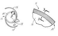
- FIG. 1is a plan view of one form of IOL constructed in accordance with the teachings of this invention.
- FIG. 1Ais an elevational view of the IOL shown in FIG. 1 .
- FIG. 2is an enlarged fragmentary view of the region generally bounded by the arc 2 in FIG. 1 and showing a more detailed view of the cell barrier portion of the IOL.
- FIG. 3is an enlarged fragmentary sectional view taken generally along 3 — 3 of FIG. 2 .
- FIG. 4is an enlarged fragmentary sectional view taken generally along line 3 — 3 of FIG. 2 and showing the growth of cells from the capsular bag of the eye on only a portion of the cell barrier region.
- FIG. 5is an enlarged fragmentary view of the region generally identified by the line 5 — 5 in FIG. 3 and showing the substantial irregularity of the grooves of the cell barrier portion.
- FIG. 6is a photograph of a portion of a cell barrier portion of an IOL in accordance with the present invention at 1000 times magnification and showing the irregular annular grooves.
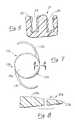
- FIG. 7is a plan view of a second form of IOL constructed in accordance with the teachings of this invention.
- FIG. 8is an enlarged fragmentary sectional view taken generally along line 8 — 8 of FIG. 7 .
- FIG. 9is a plan view with portions broken away of a third from of IOL constructed in accordance with the teachings of this invention.
- FIG. 10is an enlarged fragmentary sectional view taken generally along line 10 — 10 and illustrating another construction of the cell barrier portion.
- FIGS. 1 and 1Ashow an IOL 11 which generally comprises an optic 13 and fixation members 15 and 17 .
- the optic 13may be considered as including an optical portion 19 for focusing light on or near the retina of the eye and a cell barrier portion 21 circumscribing the optical portion and being incapable of focusing light on the retina.
- Optical axis 22passes through the center of optic 13 in a direction generally transverse to the plane of the optic.
- the optic 13is circular in plan and biconvex; however, this is purely illustrative as other configurations and shapes may be employed.
- the optic 13may be constructed of any of the commonly employed materials commonly used for rigid optics, such as polymethylmethacrylate (PMMA), or commonly used for resiliently deformable optics, such as silicone polymeric materials, acrylic polymeric materials, hydrogel-forming polymeric materials, mixtures thereof and the like.
- PMMApolymethylmethacrylate
- resiliently deformable opticssuch as silicone polymeric materials, acrylic polymeric materials, hydrogel-forming polymeric materials, mixtures thereof and the like.
- fixation members 15 and 17 in this embodimentare generally C-shaped and are integral with the optic 13 .
- fixation members 15 and 17may be of other configurations and/or may be separate members affixed to the optic in any of a variety of conventional ways.
- the optic 13has an anterior face 23 , a posterior face and a peripheral edge 27 .
- the faces and 25are convex and the peripheral edge 27 is cylindrical, but as indicated above, these shapes are shown only by way of example.
- the optic 13is designed to be placed in the capsular bag.
- the diameter of the optic 13may be conventional, and as such, may be about 6 mm or less.
- the optical portion 19performs the normal function of the optic of an IOL, i.e. to appropriately focus light at or near the retina.
- the optical portion 19may be monofocal or multifocal.
- the cell barrier portion 21is integral with the optical portion 19
- the cell barrier portion 21is incapable of focusing light on the retina of the eye and includes an irregularly configured structure or surface feature effective to inhibit, and preferably substantially prevent, cell growth radially inwardly across the cell barrier portion.
- the cell barrier portion 21includes a concentric array of annular grooves 29 each of which is at least partially defined by irregular surfaces. Similar arrays of the grooves 29 are in both the anterior face 23 and the posterior face 25 . Although various different arrangements can be employed, in this embodiment the grooves 29 are concentric and substantially equally spaced apart. Each of the grooves 29 has sufficient irregularity in its structure so as to at least inhibit migration of cells across the groove.
- each of the grooves 29has a maximum depth of no more than about 0.02 mm and a maximum width at the face 23 (or face 25 as the case may be) of no more than about 0.005 mm or about 0.01 mm or about 0.02 mm.
- the grooves 29are substantially completely defined by irregular surfaces.
- each of the grooves 29is represented by other than straight lines having a length more than about 0.001 mm, with the groove viewed in axial cross-section along a plane which includes the optical axis 22 . This irregularity of grooves 29 is illustrated in detail in FIG. 5 .
- FIG. 6is a photograph of a number of the grooves 29 which demonstrate their substantial irregularity.
- the irregularly configured structure of cell barrier portion 21acts to disrupt or otherwise interfere with the process of eye cell, for example, lens epithelial cell, migration or growth so that the cumulative effect of this irregular structure is to significantly reduce, or even eliminate, the migration or growth of cells in front of or in back of the optical portion 19 after IOL 11 is implanted in the eye.
- FIG. 4illustrates that eye cells 30 from the capsular bag 32 do migrate or grow to some extent onto and cover a portion of the cell barrier portion 21 .
- This limited cell migrationis advantageous in at least assisting or facilitating the effective fixation of IOL 11 in the eye.
- the present inventionpreferably provides for such advantageous limited eye lens epithelial cell migration or growth while preventing excessive cell migration or growth in front of or in back of the optical portion 19 , as shown in FIG. 4 .
- cell barrier portion 21Another way of viewing the degree of irregularity of the irregularly configured structure, for example, grooves 29 , on cell barrier portion 21 is opacity.
- the grooves 29are sufficiently irregular so that the cell barrier portion 21 is substantially completely opaque to the transmission of light.
- cell barrier portion 21is a white or frosty band on the otherwise optically clear optic 13 .
- grooves 29are in contrast to the regular or ordered grooves of the prior art, for example, the linear ordered grooves disclosed in Kelman U.S. Pat. No. 4,808,181.
- the Kelman groovesare defined as being ordered whereas the present grooves, such as grooves 29 , are defined by irregular, even randomly or unordered, surfaces, as described elsewhere herein. Under 1000 times magnification, the Kelman grooves are still defined (in axial cross-section) by straight lines.
- grooves 29in accordance with the present invention, are not defined (in axial cross-section) by straight lines
- the region of the Kelman IOL which includes the linear ordered groovesmay be somewhat distorted (not totally optically clear)
- this regionstill remains substantially transparent to the passage of light
- the present grooves 29 and cell barrier portion 21are substantially opaque to the transmission of light.
- the irregularity of the present cell barrier portionis an important aspect of the present invention in inhibiting the migration of eye cells onto the optical portion of the optic and clearly distinguishes the present IOLs from prior art IOLs, such as the IOLs of Kelman U.S. Pat. No. 4,808,181 and the like IOL which included regular or ordered surface grooves and the like features.
- the radial dimension of the cell barrier portion 21is no greater than about 2 mm, and more preferably no greater than 0.25 mm.
- the spacing between the grooves 29 along the face 23may be about 0.005 mm to about 0.02 mm and the radial spacing between the outermost groove 29 and the peripheral edge 27 may be about 0.02 mm to about 0.1 mm.
- the number of grooves 29is about 50 to about 100. In order to obtain an advantageous degree of cell migration inhibition, it is preferred that the number of grooves included in cell barrier portion 21 be at least about 20, although fewer grooves can provide some useful benefits.
- the grooves 29are located wherever it is desired to inhibit cell migration.
- the grooves 29are placed on both the anterior face 23 and the posterior face 25 so that the cell barrier portion 21 is on both faces of the optic 13 .
- the cell barrier portioncan be eliminated from a particular face if it is determined that cell migration in front of that face is not likely to occur.
- the IOL 11can be implanted in the capsular bag of the eye in accordance with conventional techniques.
- the cell barrier portion 21defines a radially relatively narrow annular barrier for inhibiting cell growth radially inwardly in front of or in back of the optical portion 19 where the cells could cause secondary opacification.
- the present inventionis applicable to IOLs including a hard or rigid optic, such as the optics made from PMMA, and those which include a foldable or deformable optic, such as optics comprising silicone polymeric materials, other acrylic polymeric materials, hydrogel-forming polymeric materials, such as polyhydroxyethylmethacrylate (poly HEMA), and the like.
- a foldable or deformable opticsuch as optics comprising silicone polymeric materials, other acrylic polymeric materials, hydrogel-forming polymeric materials, such as polyhydroxyethylmethacrylate (poly HEMA), and the like.
- Such foldable/deformable opticsare particularly advantageous since they can be inserted into the eye through a small incision.
- the fixation members 15 and 17are flexible and strandlike or filaments so that they can be easily inserted into the eye.
- the fixation members 15 and 17can be formed integrally with the optic 13 or can be separately coupled to the optic.
- FIGS. 7 and 8show an IOL 11 a which is identical to the IOL 11 in all respects not shown or described herein. Portions of the IOL 11 a corresponding to portions of the IOL 11 are designated by corresponding reference numerals followed by the letter a.
- the only difference between the IOL's 11 and 11 ais that in the IOL 11 a the grooves 29 are replaced with an irregularly roughened or textured surface 31 .
- the cell barrier portion 21 ain particular the roughened or textured surface 31 , is sufficiently irregular as to be at least partially, and preferably substantially completely, opaque to the transmission of light. This not only provides cell migration inhibition, but also avoids glare from the interaction of light with the cell barrier portion 21 a .
- the textured surface 31may be textured or roughened in any of a variety of ways including machining as with a lathe, chemical etching, abrading or the like. If the optic 13 a is molded, as for example when it is constructed of silicone polymeric material or other soft foldable material, the texturing or roughening of the textured surface 31 may be imparted by the mold.
- the degree of irregularity of the roughening of the surface 31should be sufficient to enable the textured surface to perform the inhibition of cell migration function.
- FIGS. 9 and 10show an IOL 11 b which is identical to the IOL 11 in all respects not shown or described herein. Portions of the IOL 11 b corresponding to portions of the IOL 11 are designated by corresponding reference numerals follows by the letter b.
- the fixation members 15 b and 17 bare separate strands or filaments which are attached to the optic 13 b in an suitable conventional manner.
- the cell barrier portion 21 bis in the form of a separate member coupled to the optical portion 19 b.
- the cell barrier 21 bincludes spaced legs 33 joined by a web 35 .
- the legs 33engage the faces 23 b and 25 b , respectively, and the web 35 confronts and engages the peripheral edge 27 b .
- the cell barrier portion 21 bis annular and extends completely around the optical portion 19 b and is mounted on the optical portion in a manner similar to a tire.
- the cell barrier portion 21 bmay have a radial width of up to about 2 mm or about 1 mm, for example, about 0.25 mm.
Landscapes
- Health & Medical Sciences (AREA)
- Ophthalmology & Optometry (AREA)
- Cardiology (AREA)
- Oral & Maxillofacial Surgery (AREA)
- Transplantation (AREA)
- Engineering & Computer Science (AREA)
- Biomedical Technology (AREA)
- Heart & Thoracic Surgery (AREA)
- Vascular Medicine (AREA)
- Life Sciences & Earth Sciences (AREA)
- Animal Behavior & Ethology (AREA)
- General Health & Medical Sciences (AREA)
- Public Health (AREA)
- Veterinary Medicine (AREA)
- Prostheses (AREA)
Abstract
Description
Claims (7)
Priority Applications (1)
| Application Number | Priority Date | Filing Date | Title |
|---|---|---|---|
| US09/859,658US6656222B2 (en) | 1995-05-09 | 2001-05-17 | IOL for reducing secondary opacification |
Applications Claiming Priority (4)
| Application Number | Priority Date | Filing Date | Title |
|---|---|---|---|
| US08/437,656US5549670A (en) | 1995-05-09 | 1995-05-09 | IOL for reducing secondary opacification |
| US08/627,723US5693094A (en) | 1995-05-09 | 1996-04-02 | IOL for reducing secondary opacification |
| US08/844,428US6258123B1 (en) | 1995-05-09 | 1997-04-18 | IOL for reducing secondary opacification |
| US09/859,658US6656222B2 (en) | 1995-05-09 | 2001-05-17 | IOL for reducing secondary opacification |
Related Parent Applications (1)
| Application Number | Title | Priority Date | Filing Date |
|---|---|---|---|
| US08/844,428DivisionUS6258123B1 (en) | 1995-05-09 | 1997-04-18 | IOL for reducing secondary opacification |
Publications (2)
| Publication Number | Publication Date |
|---|---|
| US20010034552A1 US20010034552A1 (en) | 2001-10-25 |
| US6656222B2true US6656222B2 (en) | 2003-12-02 |
Family
ID=27031393
Family Applications (3)
| Application Number | Title | Priority Date | Filing Date |
|---|---|---|---|
| US08/627,723Expired - LifetimeUS5693094A (en) | 1995-05-09 | 1996-04-02 | IOL for reducing secondary opacification |
| US08/844,428Expired - Fee RelatedUS6258123B1 (en) | 1995-05-09 | 1997-04-18 | IOL for reducing secondary opacification |
| US09/859,658Expired - Fee RelatedUS6656222B2 (en) | 1995-05-09 | 2001-05-17 | IOL for reducing secondary opacification |
Family Applications Before (2)
| Application Number | Title | Priority Date | Filing Date |
|---|---|---|---|
| US08/627,723Expired - LifetimeUS5693094A (en) | 1995-05-09 | 1996-04-02 | IOL for reducing secondary opacification |
| US08/844,428Expired - Fee RelatedUS6258123B1 (en) | 1995-05-09 | 1997-04-18 | IOL for reducing secondary opacification |
Country Status (5)
| Country | Link |
|---|---|
| US (3) | US5693094A (en) |
| EP (1) | EP0957826B1 (en) |
| JP (1) | JP3793575B2 (en) |
| DE (1) | DE69629600T2 (en) |
| WO (1) | WO1996035397A1 (en) |
Cited By (15)
| Publication number | Priority date | Publication date | Assignee | Title |
|---|---|---|---|---|
| US20030176914A1 (en)* | 2003-01-21 | 2003-09-18 | Rabkin Dmitry J. | Multi-segment modular stent and methods for manufacturing stents |
| US20040111147A1 (en)* | 2002-12-03 | 2004-06-10 | Rabkin Dmitry J. | Temporary, repositionable or retrievable intraluminal devices |
| US20040143324A1 (en)* | 2002-12-24 | 2004-07-22 | Medical Technology Transfer Holding B.V. | Cosmetic eye implant, use of such implant, method for providing such implant and eyes provided therewith |
| US20040193253A1 (en)* | 2001-04-30 | 2004-09-30 | Thorpe Patricia E | Replacement venous valve |
| US20050021141A1 (en)* | 2001-10-26 | 2005-01-27 | Bleyer Mark W. | Medical graft device with meshed structure |
| US20060129225A1 (en)* | 2004-12-15 | 2006-06-15 | Kopia Gregory A | Device for the delivery of a cardioprotective agent to ischemic reperfused myocardium |
| US20060142855A1 (en)* | 2004-12-29 | 2006-06-29 | Jerome Vaudant | Small incision intraocular lens with anti-PCO feature |
| US20070027539A1 (en)* | 2003-09-30 | 2007-02-01 | Joel Pynson | Intaocular lens for inhibiting pco and aco |
| US20070067031A1 (en)* | 2005-09-22 | 2007-03-22 | Alcon, Inc. | Intraocular lens |
| US20080077238A1 (en)* | 2006-09-21 | 2008-03-27 | Advanced Medical Optics, Inc. | Intraocular lenses for managing glare, adhesion, and cell migration |
| US20080077239A1 (en)* | 2006-09-21 | 2008-03-27 | Advanced Medical Optics, Inc. | Intraocular lenses for managing glare, adhesion, and cell migration |
| US20080269885A1 (en)* | 2007-04-30 | 2008-10-30 | Simpson Michael J | IOL Peripheral Surface Designs to Reduce Negative Dysphotopsia |
| US20080269886A1 (en)* | 2007-04-30 | 2008-10-30 | Simpson Michael J | IOL Peripheral Surface Designs to Reduce Negative Dysphotopsia |
| US20110118836A1 (en)* | 2009-11-18 | 2011-05-19 | Abbott Medical Optics Inc. | Mark for intraocular lenses |
| DE102018110194A1 (en) | 2017-04-27 | 2018-10-31 | Klaus Nordmann | eye lens |
Families Citing this family (100)
| Publication number | Priority date | Publication date | Assignee | Title |
|---|---|---|---|---|
| US5693094A (en)* | 1995-05-09 | 1997-12-02 | Allergan | IOL for reducing secondary opacification |
| JP4413280B2 (en)* | 1997-01-21 | 2010-02-10 | アニルテルソ ゲーエムベーハー | Artificial lens manufacturing method |
| JP3850538B2 (en)* | 1997-07-19 | 2006-11-29 | 敏之 永本 | Lens capsule adhesion prevention ring |
| JP3805496B2 (en)* | 1997-08-29 | 2006-08-02 | 株式会社ニデック | Intraocular lens |
| US6129759A (en)* | 1997-12-10 | 2000-10-10 | Staar Surgical Company, Inc. | Frosted haptic intraocular lens |
| US6482230B1 (en) | 1998-04-15 | 2002-11-19 | Alcon Manufacturing, Ltd. | Lens epithelial cell growth assay for intraocular lens materials |
| US6455318B1 (en) | 1998-04-15 | 2002-09-24 | Alcon Manufacturing, Ltd. | Collagen IV adhesion assay for intraocular lens materials |
| US6210438B1 (en)* | 1998-04-15 | 2001-04-03 | Alcon Laboratories, Inc. | Bicomposite intraocular lens and method for its preparation |
| US6491721B2 (en) | 1998-04-15 | 2002-12-10 | Alcon Manufacturing, Ltd. | Toric intraocular lens material |
| ES2162518T3 (en) | 1998-04-15 | 2001-12-16 | Alcon Lab Inc | INTRAOCULAR LENS COATING COMPOSITIONS. |
| US6416550B2 (en) | 1998-04-15 | 2002-07-09 | Alcon Manufacturing, Ltd. | Method of selecting an intraocular lens material |
| US6468306B1 (en) | 1998-05-29 | 2002-10-22 | Advanced Medical Optics, Inc | IOL for inhibiting cell growth and reducing glare |
| US6884262B2 (en)* | 1998-05-29 | 2005-04-26 | Advanced Medical Optics, Inc. | Enhanced intraocular lens for reducing glare |
| US20060238702A1 (en) | 1999-04-30 | 2006-10-26 | Advanced Medical Optics, Inc. | Ophthalmic lens combinations |
| JP4828065B2 (en) | 1999-11-24 | 2011-11-30 | アボット・メディカル・オプティクス・インコーポレイテッド | IOL suppresses cell growth and reduces flicker |
| DE10055888C1 (en)* | 2000-11-10 | 2002-04-25 | Biedermann Motech Gmbh | Bone screw, has connector rod receiving part with unsymmetrically arranged end bores |
| US20030078657A1 (en) | 2001-01-25 | 2003-04-24 | Gholam-Reza Zadno-Azizi | Materials for use in accommodating intraocular lens system |
| US6884261B2 (en)* | 2001-01-25 | 2005-04-26 | Visiogen, Inc. | Method of preparing an intraocular lens for implantation |
| US8062361B2 (en)* | 2001-01-25 | 2011-11-22 | Visiogen, Inc. | Accommodating intraocular lens system with aberration-enhanced performance |
| US7780729B2 (en) | 2004-04-16 | 2010-08-24 | Visiogen, Inc. | Intraocular lens |
| US6786934B2 (en) | 2001-01-25 | 2004-09-07 | Visiogen, Inc. | Biasing element for intraocular lens system |
| US20030078658A1 (en) | 2001-01-25 | 2003-04-24 | Gholam-Reza Zadno-Azizi | Single-piece accomodating intraocular lens system |
| US6703466B1 (en) | 2001-06-18 | 2004-03-09 | Alcon, Inc. | Foldable intraocular lens optics having a glassy surface |
| US6558419B1 (en) | 2001-11-08 | 2003-05-06 | Bausch & Lomb Incorporated | Intraocular lens |
| US7763069B2 (en) | 2002-01-14 | 2010-07-27 | Abbott Medical Optics Inc. | Accommodating intraocular lens with outer support structure |
| US6648741B2 (en) | 2002-03-14 | 2003-11-18 | Advanced Medical Optics, Inc. | Apparatus for protecting the edge geometry of an intraocular lens during glass bead polishing process |
| US20040002757A1 (en)* | 2002-06-27 | 2004-01-01 | Bausch & Lomb Incorporated | Intraocular lens |
| TW586923B (en)* | 2002-10-25 | 2004-05-11 | Ming-Lin Tsai | Intraocular lens with photocatalytic coating |
| US7662180B2 (en) | 2002-12-05 | 2010-02-16 | Abbott Medical Optics Inc. | Accommodating intraocular lens and method of manufacture thereof |
| FR2849592B1 (en)* | 2003-01-08 | 2005-03-25 | Ioltechnologie Production | CAPSULAR RING, METHOD OF MANUFACTURING CAPSULAR RING AND CAPSULAR RING ASSEMBLY AND INTRAOCULAR LENS |
| US7615056B2 (en)* | 2003-02-14 | 2009-11-10 | Visiogen, Inc. | Method and device for compacting an intraocular lens |
| US20040188872A1 (en)* | 2003-03-31 | 2004-09-30 | Jani Dharmendra M. | Method for fabricating intraocular lens with peripheral sharp edge |
| US7628810B2 (en) | 2003-05-28 | 2009-12-08 | Acufocus, Inc. | Mask configured to maintain nutrient transport without producing visible diffraction patterns |
| US20050046794A1 (en) | 2003-06-17 | 2005-03-03 | Silvestrini Thomas A. | Method and apparatus for aligning a mask with the visual axis of an eye |
| US6960231B2 (en)* | 2003-07-14 | 2005-11-01 | Alcon, Inc. | Intraocular lens system |
| US7615073B2 (en) | 2003-12-09 | 2009-11-10 | Advanced Medical Optics, Inc. | Foldable intraocular lens and method of making |
| CA2548735C (en) | 2003-12-09 | 2012-11-13 | Advanced Medical Optics, Inc. | Foldable intraocular lens and method of making |
| US20050131535A1 (en) | 2003-12-15 | 2005-06-16 | Randall Woods | Intraocular lens implant having posterior bendable optic |
| US7645300B2 (en)* | 2004-02-02 | 2010-01-12 | Visiogen, Inc. | Injector for intraocular lens system |
| DE102004027236B4 (en)* | 2004-06-03 | 2006-04-13 | Morcher Gmbh | Capsular equatorial ring |
| US7806930B2 (en)* | 2004-08-27 | 2010-10-05 | Brown David C | Device for attachment to a capsule in an eye |
| US7806929B2 (en)* | 2004-08-27 | 2010-10-05 | Brown David C | Intracapsular pseudophakic device |
| WO2006034436A2 (en) | 2004-09-21 | 2006-03-30 | Stout Medical Group, L.P. | Expandable support device and method of use |
| US8377123B2 (en) | 2004-11-10 | 2013-02-19 | Visiogen, Inc. | Method of implanting an intraocular lens |
| EP1903949A2 (en) | 2005-07-14 | 2008-04-02 | Stout Medical Group, L.P. | Expandable support device and method of use |
| US20070032866A1 (en)* | 2005-08-05 | 2007-02-08 | Valdemar Portney | Accommodating diffractive intraocular lens |
| US9636213B2 (en) | 2005-09-30 | 2017-05-02 | Abbott Medical Optics Inc. | Deformable intraocular lenses and lens systems |
| US20070168027A1 (en)* | 2006-01-13 | 2007-07-19 | Brady Daniel G | Accommodating diffractive intraocular lens |
| EP1984035A2 (en) | 2006-02-13 | 2008-10-29 | Medtronic, Inc. | Medical devices having textured surfaces |
| EP2023864B1 (en) | 2006-05-01 | 2019-07-10 | Stout Medical Group, L.P. | Expandable support device |
| US8403984B2 (en) | 2006-11-29 | 2013-03-26 | Visiogen, Inc. | Apparatus and methods for compacting an intraocular lens |
| EP2124822B1 (en) | 2006-12-22 | 2019-02-20 | AMO Groningen B.V. | Accommodating intraocular lens, lens system and frame therefor |
| US20080161914A1 (en) | 2006-12-29 | 2008-07-03 | Advanced Medical Optics, Inc. | Pre-stressed haptic for accommodating intraocular lens |
| US20080269881A1 (en)* | 2007-04-30 | 2008-10-30 | Simpson Michael J | Intraocular Lens with Asymmetric Haptics |
| US20080269889A1 (en)* | 2007-04-30 | 2008-10-30 | Simpson Michael J | Haptic Junction Designs to Reduce Negative Dysphotopsia |
| US20080269882A1 (en)* | 2007-04-30 | 2008-10-30 | Alcon Universal Ltd. | Intraocular lens with asymmetric optics |
| US20080269891A1 (en)* | 2007-04-30 | 2008-10-30 | Alcon, Inc. | Intraocular lens with edge modification |
| US20080269890A1 (en)* | 2007-04-30 | 2008-10-30 | Alcon Universal Ltd. | Intraocular lens with peripheral region designed to reduce negative dysphotopsia |
| US20080269883A1 (en)* | 2007-04-30 | 2008-10-30 | Alcon, Inc. | Ocular implant to correct dysphotopsia, glare, halos and dark shadow type phenomena |
| US7660927B2 (en)* | 2007-05-21 | 2010-02-09 | International Business Machines Corporation | Apparatus and method to control access to stored information |
| US20090228101A1 (en) | 2007-07-05 | 2009-09-10 | Visiogen, Inc. | Intraocular lens with post-implantation adjustment capabilities |
| FR2922096B1 (en)* | 2007-10-16 | 2010-01-08 | Ioltechnologie Production | INTRAOCULAR LENS FOR CAPSULAR BAG |
| US8425595B2 (en) | 2008-03-12 | 2013-04-23 | Visiogen, Inc. | Method for inserting an intraocular lens |
| US8034108B2 (en) | 2008-03-28 | 2011-10-11 | Abbott Medical Optics Inc. | Intraocular lens having a haptic that includes a cap |
| JP4527201B2 (en)* | 2008-07-15 | 2010-08-18 | 株式会社メニコン | Intraocular lens and manufacturing method thereof |
| US9089419B2 (en)* | 2008-10-15 | 2015-07-28 | Novartis Ag | System to reduce surface contact between optic and haptic areas |
| WO2010056895A1 (en) | 2008-11-12 | 2010-05-20 | Stout Medical Group, L.P. | Fixation device and method |
| US20100211176A1 (en) | 2008-11-12 | 2010-08-19 | Stout Medical Group, L.P. | Fixation device and method |
| US20120232649A1 (en)* | 2008-11-20 | 2012-09-13 | Insight Innovations, Llc | Intraocular Lens Cell Migration Inhibition System |
| EP2364127B1 (en) | 2008-11-20 | 2016-08-31 | Insight Innovations, Llc | Biocompatible biodegradable intraocular implant system |
| US9943402B2 (en) | 2008-11-20 | 2018-04-17 | Insight Innovations, Llc | Micropatterned intraocular implant |
| WO2010151691A2 (en) | 2009-06-26 | 2010-12-29 | Abbott Medical Optics Inc. | Accommodating intraocular lenses |
| CA2770074C (en) | 2009-08-03 | 2017-09-05 | Abbott Medical Optics Inc. | Intraocular lens for providing accomodative vision |
| WO2011020074A1 (en) | 2009-08-13 | 2011-02-17 | Acufocus, Inc. | Corneal inlay with nutrient transport structures |
| US10004593B2 (en) | 2009-08-13 | 2018-06-26 | Acufocus, Inc. | Intraocular lens with elastic mask |
| CA2770735C (en) | 2009-08-13 | 2017-07-18 | Acufocus, Inc. | Masked intraocular implants and lenses |
| US8535380B2 (en) | 2010-05-13 | 2013-09-17 | Stout Medical Group, L.P. | Fixation device and method |
| EP2608747A4 (en) | 2010-08-24 | 2015-02-11 | Flexmedex Llc | Support device and method for use |
| US9149286B1 (en) | 2010-11-12 | 2015-10-06 | Flexmedex, LLC | Guidance tool and method for use |
| US8771347B2 (en)* | 2011-05-23 | 2014-07-08 | California Institute Of Technology | Accommodating intraocular lens |
| EP2747682A4 (en) | 2011-08-23 | 2015-01-21 | Flexmedex Llc | Tissue removal device and method |
| US11364108B2 (en)* | 2011-09-14 | 2022-06-21 | Investmed Kft. | Intraocular lens for implantation in a ciliary sulcus of an eye |
| US12036111B2 (en)* | 2011-09-14 | 2024-07-16 | Medicontur Holding Ltd. | Method of implantation of an intraocular lens in a ciliary sulcus of an eye |
| JP6046160B2 (en) | 2011-12-02 | 2016-12-14 | アキュフォーカス・インコーポレーテッド | Ophthalmic mask with selective spectral transmission |
| US9084674B2 (en) | 2012-05-02 | 2015-07-21 | Abbott Medical Optics Inc. | Intraocular lens with shape changing capability to provide enhanced accomodation and visual acuity |
| US9204962B2 (en) | 2013-03-13 | 2015-12-08 | Acufocus, Inc. | In situ adjustable optical mask |
| US9427922B2 (en) | 2013-03-14 | 2016-08-30 | Acufocus, Inc. | Process for manufacturing an intraocular lens with an embedded mask |
| CN106817894A (en)* | 2014-08-07 | 2017-06-09 | 幼鲨科技股份有限公司 | Patterns for flow control and bioadhesion control |
| US9943403B2 (en) | 2014-11-19 | 2018-04-17 | Acufocus, Inc. | Fracturable mask for treating presbyopia |
| US11696823B2 (en) | 2015-04-14 | 2023-07-11 | Z Optics, Inc. | High definition and extended depth of field intraocular lens |
| US11547554B2 (en) | 2015-04-14 | 2023-01-10 | Z Optics, Inc. | High definition and extended depth of field intraocular lens |
| ES2972581T3 (en) | 2015-10-05 | 2024-06-13 | Acufocus Inc | Intraocular lens molding methods |
| KR102407311B1 (en) | 2015-11-24 | 2022-06-10 | 아큐포커스, 인크. | Toroidal eyelet intraocular lens with extended depth of focus |
| EP3681438A1 (en) | 2017-09-11 | 2020-07-22 | AMO Groningen B.V. | Methods and apparatuses to increase intraocular lenses positional stability |
| AU2018337957A1 (en)* | 2017-09-20 | 2020-04-02 | Clearsight, Llc | Single piece intra-ocular lenses and methods of manufacture thereof |
| EP3790508A4 (en) | 2018-05-09 | 2022-02-09 | AcuFocus, Inc. | INTRAOCULAR IMPLANT WITH REMOVABLE OPTICS |
| KR102263427B1 (en)* | 2019-05-02 | 2021-06-11 | 한국과학기술연구원 | Intraocular lens and method of manufacturing the same |
| EP3982880A4 (en)* | 2019-06-13 | 2023-08-09 | Z Optics, Inc. | EXTENDED DEPTH OF FIELD HIGH DEFINITION INTRAOCULAR LENS |
| DE102019134301A1 (en)* | 2019-12-13 | 2021-06-17 | Carl Zeiss Meditec Ag | Ophthalmic implant |
| US12295831B2 (en) | 2023-10-23 | 2025-05-13 | California Institute Of Technology | Liquid accommodating intraocular lens with an asymmetric chamber |
Citations (35)
| Publication number | Priority date | Publication date | Assignee | Title |
|---|---|---|---|---|
| US2043840A (en) | 1934-06-23 | 1936-06-09 | Optical Res Corp | Ophthalmic lens |
| US3034403A (en) | 1959-04-03 | 1962-05-15 | Neefe Hamilton Res Company | Contact lens of apparent variable light absorption |
| US3454332A (en) | 1966-11-03 | 1969-07-08 | Robert Siegel | Corneal plastic contact lens with colored peripheral zone |
| US4429421A (en) | 1982-02-03 | 1984-02-07 | Levy Chauncey F | Method of implanting an intraocular lens |
| US4435856A (en) | 1982-04-14 | 1984-03-13 | Esperance Francis A L | Bifocal intraocular lens structure and spectacle actuation frame |
| US4449257A (en) | 1982-05-03 | 1984-05-22 | Barnes-Hind/Hydrocurve, Inc. | Intraocular lens and method of retaining in place |
| US4451938A (en) | 1982-09-24 | 1984-06-05 | Kelman Charles D | Intraocular lens and method of positioning the same in an eye |
| US4601722A (en) | 1984-10-30 | 1986-07-22 | Kelman Charles D | Intraocular lens |
| US4605409A (en) | 1984-05-21 | 1986-08-12 | Kelman Charles D | Intraocular lens with miniature optic having expandable and contractible glare-reducing means |
| GB2181355A (en) | 1985-10-15 | 1987-04-23 | Storz Instr Co | Lens implant |
| US4676791A (en) | 1985-08-01 | 1987-06-30 | Surgidev Corporation | Intraocular lens and method for making same |
| US4702244A (en) | 1982-02-05 | 1987-10-27 | Staar Surgical Company | Surgical device for implantation of a deformable intraocular lens |
| EP0246754A1 (en) | 1986-04-21 | 1987-11-25 | Kelman, Charles D. | Intraocular lens having glare-inhibiting means |
| US4743254A (en) | 1985-01-31 | 1988-05-10 | American Hospital Supply Company | Small incision intraocular lens |
| US4808181A (en) | 1987-08-07 | 1989-02-28 | Kelman Charles D | Intraocular lens having roughened surface area |
| US5002571A (en) | 1989-02-06 | 1991-03-26 | Donnell Jr Francis E O | Intraocular lens implant and method of locating and adhering within the posterior chamber |
| US5011494A (en) | 1988-09-16 | 1991-04-30 | Clemson University | Soft tissue implant with micron-scale surface texture to optimize anchorage |
| FR2661816A1 (en) | 1990-05-14 | 1991-11-15 | Arneodo Jacques | Artificial crystalline lens comprising means promoting implantation in order to ensure imperviousness and prevent the migration of the aqueous humor towards the rear |
| EP0457553A2 (en) | 1990-05-14 | 1991-11-21 | Iolab Corporation | Multifocal multizone diffractive ophthalmic lenses |
| EP0458508A2 (en) | 1990-05-14 | 1991-11-27 | Iolab Corporation | A tuned fresnel lens for multifocal intraocular applications including small incision surgeries |
| US5074876A (en) | 1987-12-04 | 1991-12-24 | Kelman Charles D | Two piece intraocular lens |
| US5076684A (en) | 1988-04-01 | 1991-12-31 | Minnesota Mining And Manufacturing Company | Multi-focal diffractive ophthalmic lenses |
| US5089023A (en) | 1990-03-22 | 1992-02-18 | Massachusetts Institute Of Technology | Diffractive/refractive lens implant |
| US5108428A (en) | 1988-03-02 | 1992-04-28 | Minnesota Mining And Manufacturing Company | Corneal implants and manufacture and use thereof |
| WO1993000204A1 (en) | 1991-06-24 | 1993-01-07 | The Gillette Company | Improvements in or relating to razor blades |
| US5366501A (en) | 1993-05-12 | 1994-11-22 | Langerman David W | Intraocular lens with dual 360 degree haptics |
| US5370687A (en) | 1991-11-14 | 1994-12-06 | Poler; Stanley | Implantable device and method for impeding secondary growth within an eye |
| US5405385A (en) | 1992-04-02 | 1995-04-11 | Clemson University | Intraocular lens with integrated means of fixation |
| US5549670A (en)* | 1995-05-09 | 1996-08-27 | Allergan, Inc. | IOL for reducing secondary opacification |
| US5693074A (en) | 1993-12-06 | 1997-12-02 | Pacesetter Ab | Cardiac electrotherapy device for cardiac contraction measurement |
| US5713956A (en) | 1991-04-10 | 1998-02-03 | F.C.I. (France Chirurgie Instrumentation) | Microporous support for a keratoprosthesis |
| US6129759A (en) | 1997-12-10 | 2000-10-10 | Staar Surgical Company, Inc. | Frosted haptic intraocular lens |
| US6258123B1 (en)* | 1995-05-09 | 2001-07-10 | Allergan | IOL for reducing secondary opacification |
| US20020095211A1 (en)* | 1995-05-09 | 2002-07-18 | Craig Young | IOL for reducing secondary opacification |
| US6468306B1 (en)* | 1998-05-29 | 2002-10-22 | Advanced Medical Optics, Inc | IOL for inhibiting cell growth and reducing glare |
Family Cites Families (1)
| Publication number | Priority date | Publication date | Assignee | Title |
|---|---|---|---|---|
| US5260828A (en)* | 1992-03-27 | 1993-11-09 | Polaroid Corporation | Methods and means for reducing temperature-induced variations in lenses and lens devices |
- 1996
- 1996-04-02USUS08/627,723patent/US5693094A/ennot_activeExpired - Lifetime
- 1996-04-16DEDE69629600Tpatent/DE69629600T2/ennot_activeExpired - Fee Related
- 1996-04-16JPJP53407796Apatent/JP3793575B2/ennot_activeExpired - Lifetime
- 1996-04-16EPEP96911793Apatent/EP0957826B1/ennot_activeExpired - Lifetime
- 1996-04-16WOPCT/US1996/005301patent/WO1996035397A1/enactiveIP Right Grant
- 1997
- 1997-04-18USUS08/844,428patent/US6258123B1/ennot_activeExpired - Fee Related
- 2001
- 2001-05-17USUS09/859,658patent/US6656222B2/ennot_activeExpired - Fee Related
Patent Citations (35)
| Publication number | Priority date | Publication date | Assignee | Title |
|---|---|---|---|---|
| US2043840A (en) | 1934-06-23 | 1936-06-09 | Optical Res Corp | Ophthalmic lens |
| US3034403A (en) | 1959-04-03 | 1962-05-15 | Neefe Hamilton Res Company | Contact lens of apparent variable light absorption |
| US3454332A (en) | 1966-11-03 | 1969-07-08 | Robert Siegel | Corneal plastic contact lens with colored peripheral zone |
| US4429421A (en) | 1982-02-03 | 1984-02-07 | Levy Chauncey F | Method of implanting an intraocular lens |
| US4702244A (en) | 1982-02-05 | 1987-10-27 | Staar Surgical Company | Surgical device for implantation of a deformable intraocular lens |
| US4435856A (en) | 1982-04-14 | 1984-03-13 | Esperance Francis A L | Bifocal intraocular lens structure and spectacle actuation frame |
| US4449257A (en) | 1982-05-03 | 1984-05-22 | Barnes-Hind/Hydrocurve, Inc. | Intraocular lens and method of retaining in place |
| US4451938A (en) | 1982-09-24 | 1984-06-05 | Kelman Charles D | Intraocular lens and method of positioning the same in an eye |
| US4605409A (en) | 1984-05-21 | 1986-08-12 | Kelman Charles D | Intraocular lens with miniature optic having expandable and contractible glare-reducing means |
| US4601722A (en) | 1984-10-30 | 1986-07-22 | Kelman Charles D | Intraocular lens |
| US4743254A (en) | 1985-01-31 | 1988-05-10 | American Hospital Supply Company | Small incision intraocular lens |
| US4676791A (en) | 1985-08-01 | 1987-06-30 | Surgidev Corporation | Intraocular lens and method for making same |
| GB2181355A (en) | 1985-10-15 | 1987-04-23 | Storz Instr Co | Lens implant |
| EP0246754A1 (en) | 1986-04-21 | 1987-11-25 | Kelman, Charles D. | Intraocular lens having glare-inhibiting means |
| US4808181A (en) | 1987-08-07 | 1989-02-28 | Kelman Charles D | Intraocular lens having roughened surface area |
| US5074876A (en) | 1987-12-04 | 1991-12-24 | Kelman Charles D | Two piece intraocular lens |
| US5108428A (en) | 1988-03-02 | 1992-04-28 | Minnesota Mining And Manufacturing Company | Corneal implants and manufacture and use thereof |
| US5076684A (en) | 1988-04-01 | 1991-12-31 | Minnesota Mining And Manufacturing Company | Multi-focal diffractive ophthalmic lenses |
| US5011494A (en) | 1988-09-16 | 1991-04-30 | Clemson University | Soft tissue implant with micron-scale surface texture to optimize anchorage |
| US5002571A (en) | 1989-02-06 | 1991-03-26 | Donnell Jr Francis E O | Intraocular lens implant and method of locating and adhering within the posterior chamber |
| US5089023A (en) | 1990-03-22 | 1992-02-18 | Massachusetts Institute Of Technology | Diffractive/refractive lens implant |
| EP0458508A2 (en) | 1990-05-14 | 1991-11-27 | Iolab Corporation | A tuned fresnel lens for multifocal intraocular applications including small incision surgeries |
| EP0457553A2 (en) | 1990-05-14 | 1991-11-21 | Iolab Corporation | Multifocal multizone diffractive ophthalmic lenses |
| FR2661816A1 (en) | 1990-05-14 | 1991-11-15 | Arneodo Jacques | Artificial crystalline lens comprising means promoting implantation in order to ensure imperviousness and prevent the migration of the aqueous humor towards the rear |
| US5713956A (en) | 1991-04-10 | 1998-02-03 | F.C.I. (France Chirurgie Instrumentation) | Microporous support for a keratoprosthesis |
| WO1993000204A1 (en) | 1991-06-24 | 1993-01-07 | The Gillette Company | Improvements in or relating to razor blades |
| US5370687A (en) | 1991-11-14 | 1994-12-06 | Poler; Stanley | Implantable device and method for impeding secondary growth within an eye |
| US5405385A (en) | 1992-04-02 | 1995-04-11 | Clemson University | Intraocular lens with integrated means of fixation |
| US5366501A (en) | 1993-05-12 | 1994-11-22 | Langerman David W | Intraocular lens with dual 360 degree haptics |
| US5693074A (en) | 1993-12-06 | 1997-12-02 | Pacesetter Ab | Cardiac electrotherapy device for cardiac contraction measurement |
| US5549670A (en)* | 1995-05-09 | 1996-08-27 | Allergan, Inc. | IOL for reducing secondary opacification |
| US6258123B1 (en)* | 1995-05-09 | 2001-07-10 | Allergan | IOL for reducing secondary opacification |
| US20020095211A1 (en)* | 1995-05-09 | 2002-07-18 | Craig Young | IOL for reducing secondary opacification |
| US6129759A (en) | 1997-12-10 | 2000-10-10 | Staar Surgical Company, Inc. | Frosted haptic intraocular lens |
| US6468306B1 (en)* | 1998-05-29 | 2002-10-22 | Advanced Medical Optics, Inc | IOL for inhibiting cell growth and reducing glare |
Cited By (20)
| Publication number | Priority date | Publication date | Assignee | Title |
|---|---|---|---|---|
| US20040193253A1 (en)* | 2001-04-30 | 2004-09-30 | Thorpe Patricia E | Replacement venous valve |
| US20050021141A1 (en)* | 2001-10-26 | 2005-01-27 | Bleyer Mark W. | Medical graft device with meshed structure |
| US20040111147A1 (en)* | 2002-12-03 | 2004-06-10 | Rabkin Dmitry J. | Temporary, repositionable or retrievable intraluminal devices |
| US20040143324A1 (en)* | 2002-12-24 | 2004-07-22 | Medical Technology Transfer Holding B.V. | Cosmetic eye implant, use of such implant, method for providing such implant and eyes provided therewith |
| US20030176914A1 (en)* | 2003-01-21 | 2003-09-18 | Rabkin Dmitry J. | Multi-segment modular stent and methods for manufacturing stents |
| US20070027539A1 (en)* | 2003-09-30 | 2007-02-01 | Joel Pynson | Intaocular lens for inhibiting pco and aco |
| US20060129225A1 (en)* | 2004-12-15 | 2006-06-15 | Kopia Gregory A | Device for the delivery of a cardioprotective agent to ischemic reperfused myocardium |
| US7569073B2 (en) | 2004-12-29 | 2009-08-04 | Bausch & Lomb Incorporated | Small incision intraocular lens with anti-PCO feature |
| US20060142855A1 (en)* | 2004-12-29 | 2006-06-29 | Jerome Vaudant | Small incision intraocular lens with anti-PCO feature |
| US7931686B2 (en) | 2004-12-29 | 2011-04-26 | Bausch & Lomb Incorporated | Small incision intraocular lens with anti-PCO feature |
| US20070067031A1 (en)* | 2005-09-22 | 2007-03-22 | Alcon, Inc. | Intraocular lens |
| US20080077239A1 (en)* | 2006-09-21 | 2008-03-27 | Advanced Medical Optics, Inc. | Intraocular lenses for managing glare, adhesion, and cell migration |
| US20080077238A1 (en)* | 2006-09-21 | 2008-03-27 | Advanced Medical Optics, Inc. | Intraocular lenses for managing glare, adhesion, and cell migration |
| US8568478B2 (en) | 2006-09-21 | 2013-10-29 | Abbott Medical Optics Inc. | Intraocular lenses for managing glare, adhesion, and cell migration |
| US9603702B2 (en) | 2006-09-21 | 2017-03-28 | Abbott Medical Optics Inc. | Intraocular lenses for managing glare, adhesion, and cell migration |
| US20080269886A1 (en)* | 2007-04-30 | 2008-10-30 | Simpson Michael J | IOL Peripheral Surface Designs to Reduce Negative Dysphotopsia |
| US20080269885A1 (en)* | 2007-04-30 | 2008-10-30 | Simpson Michael J | IOL Peripheral Surface Designs to Reduce Negative Dysphotopsia |
| US20110118836A1 (en)* | 2009-11-18 | 2011-05-19 | Abbott Medical Optics Inc. | Mark for intraocular lenses |
| US8357196B2 (en) | 2009-11-18 | 2013-01-22 | Abbott Medical Optics Inc. | Mark for intraocular lenses |
| DE102018110194A1 (en) | 2017-04-27 | 2018-10-31 | Klaus Nordmann | eye lens |
Also Published As
| Publication number | Publication date |
|---|---|
| EP0957826B1 (en) | 2003-08-20 |
| US20010034552A1 (en) | 2001-10-25 |
| JPH11505453A (en) | 1999-05-21 |
| DE69629600T2 (en) | 2004-06-24 |
| WO1996035397A1 (en) | 1996-11-14 |
| EP0957826A1 (en) | 1999-11-24 |
| US6258123B1 (en) | 2001-07-10 |
| JP3793575B2 (en) | 2006-07-05 |
| DE69629600D1 (en) | 2003-09-25 |
| US5693094A (en) | 1997-12-02 |
Similar Documents
| Publication | Publication Date | Title |
|---|---|---|
| US6656222B2 (en) | IOL for reducing secondary opacification | |
| US5549670A (en) | IOL for reducing secondary opacification | |
| US6162249A (en) | IOI for inhibiting cell growth and reducing glare | |
| US6096077A (en) | Deformable intraocular corrective lens | |
| US6488707B1 (en) | Method of implanting a deformable intraocular corrective lens | |
| US6228115B1 (en) | Intraocular lenses with improved axial stability | |
| US20080288064A1 (en) | IOL For Reducing Secondary Opacification | |
| US6960231B2 (en) | Intraocular lens system | |
| US6197057B1 (en) | Lens conversion system for teledioptic or difractive configurations | |
| US6461384B1 (en) | Intraocular lenses | |
| US4932970A (en) | Ophthalmic lens | |
| JP3958576B2 (en) | Perspective accommodation intraocular lens | |
| CA2389923C (en) | Intraocular lens system | |
| US7252683B2 (en) | Intraocular lens for inhibiting cell growth and reducing glare | |
| US6342073B1 (en) | Intraocular lens for posterior vaulting | |
| US20020087210A1 (en) | Intraocular | |
| US20020103536A1 (en) | Intracocular lenses | |
| US20020095211A1 (en) | IOL for reducing secondary opacification |
Legal Events
| Date | Code | Title | Description |
|---|---|---|---|
| AS | Assignment | Owner name:BANK OF AMERICA, N.A., NEW YORK Free format text:SECURITY AGREEMENT;ASSIGNORS:ADVANCED MEDICAL OPTICS, INC.;AMO HOLDINGS, LLC;REEL/FRAME:013203/0039 Effective date:20020621 | |
| AS | Assignment | Owner name:ADVANCED MEDICAL OPTICS, INC., CALIFORNIA Free format text:ASSIGNMENT OF ASSIGNORS INTEREST;ASSIGNORS:ALLERGAN, INC.;PHARMACEUTICALS, INC.;HEYER-SCHULTE CORPORATION;AND OTHERS;REEL/FRAME:013813/0411 Effective date:20030207 | |
| AS | Assignment | Owner name:AMO HOLDINGS, INC. (FORMERLY KNOWN AS AMO HOLDINGS Free format text:RELEASE OF SECURITY INTEREST AT REEL/FRAME NO. 13203/0039;ASSIGNOR:BANK OF AMERICA, N.A.;REEL/FRAME:019111/0348 Effective date:20070402 Owner name:ADVANCED MEDICAL OPTICS, INC., CALIFORNIA Free format text:RELEASE OF SECURITY INTEREST AT REEL/FRAME NO. 13203/0039;ASSIGNOR:BANK OF AMERICA, N.A.;REEL/FRAME:019111/0348 Effective date:20070402 | |
| REMI | Maintenance fee reminder mailed | ||
| LAPS | Lapse for failure to pay maintenance fees | ||
| STCH | Information on status: patent discontinuation | Free format text:PATENT EXPIRED DUE TO NONPAYMENT OF MAINTENANCE FEES UNDER 37 CFR 1.362 | |
| FP | Lapsed due to failure to pay maintenance fee | Effective date:20071202 | |
| AS | Assignment | Owner name:YOUNG, CRAIG,MAINE Free format text:ASSIGNMENT OF ASSIGNORS INTEREST;ASSIGNOR:ABBOTT MEDICAL OPTICS INC.;REEL/FRAME:024492/0475 Effective date:20100520 |