US6656199B1 - Magnetic clamp assembly for an elongated flexible medical device - Google Patents
Magnetic clamp assembly for an elongated flexible medical deviceDownload PDFInfo
- Publication number
- US6656199B1 US6656199B1US09/645,222US64522200AUS6656199B1US 6656199 B1US6656199 B1US 6656199B1US 64522200 AUS64522200 AUS 64522200AUS 6656199 B1US6656199 B1US 6656199B1
- Authority
- US
- United States
- Prior art keywords
- clamp
- elongated
- guidewire
- spaced
- catheter
- Prior art date
- Legal status (The legal status is an assumption and is not a legal conclusion. Google has not performed a legal analysis and makes no representation as to the accuracy of the status listed.)
- Expired - Fee Related, expires
Links
Images


Classifications
- A—HUMAN NECESSITIES
- A61—MEDICAL OR VETERINARY SCIENCE; HYGIENE
- A61M—DEVICES FOR INTRODUCING MEDIA INTO, OR ONTO, THE BODY; DEVICES FOR TRANSDUCING BODY MEDIA OR FOR TAKING MEDIA FROM THE BODY; DEVICES FOR PRODUCING OR ENDING SLEEP OR STUPOR
- A61M25/00—Catheters; Hollow probes
- A61M25/01—Introducing, guiding, advancing, emplacing or holding catheters
- A61M25/0105—Steering means as part of the catheter or advancing means; Markers for positioning
- A61M25/0127—Magnetic means; Magnetic markers
Definitions
- the present inventionrelates to the field of medical devices such as elongated flexible catheter and accessory devices.
- the present inventionrelates to a magnetic clamp assembly for retaining elongated flexible medical devices in a coiled or collapsed condition and has particular application for angioplasty devices.
- Catheter and other treatment devicesare formed of elongated members which are relatively flexible for insertion into a body vessel of a patient for treatment.
- the length of various catheter or treatment devicesis relatively long to track the device to a remote treatment site.
- typically the length of an angioplasty catheteris approximately 150 cm long and a guidewire is approximately 175 cm long.
- Catheter and other treatment devicesare sterilized for human use.
- the catheter or other devicePrior to use and reuse, the catheter or other device must remain in a sterile zone or field.
- the extended length of catheters and other treatment devicesare packaged in sterile containers in a coiled configuration. Once removed from the sterile packaging, the entire length of the device must remain in the sterile field for use and reuse.
- the sterile zone or fieldis typically a sterile cart, operating table or localized treatment area. The long length of catheters or other devices makes it awkward to control and handle the device and retain the device in the sterile field.
- Angioplasty devicesare intravascularly inserted into a patient for treating coronary heart disease.
- Angioplasty devicesinclude an elongated catheter having a dilation balloon supported at a distal end which is inserted over an elongated guidewire.
- cathetersoften several different types are employed sequentially utilizing the same guidewire and in some cases the catheter may be alternately used several times.
- the catheterOnce removed from the guidewire, the catheter must be kept in a sterile field for re-use. As previously discussed, the length of the catheter shaft makes it quite awkward and inconvenient to retain the catheter in the sterile field for reuse.
- catheter devices usedinclude fixed wire catheters, over-the-wire catheters and single operator exchange catheters.
- a doctormay decide to exchange an inserted catheter device with another catheter device.
- a guidewire extensioncan be added to the end of the guidewire or an original wire can be replaced with an exchange guidewire. It is important to assure that the length of guidewire extension or exchange guidewire remains sterile and does not drop on the floor. However, the additional length of the guidewire extension or exchange guidewire makes it difficult to retain the length of the guidewire in the sterile field.
- Prior mechanical clip devicesare known to retain elongated catheters in a coiled configuration for use and reuse. These devices can be cumbersome to use and can require two hands to operate.
- the present inventionaddress these and other problems and has wide application for various angioplasty catheter devices such as cutting devices, fiber optic catheters, ultrasound probes and other treatment devices.
- the present inventionrelates to a magnetic clamp assembly for an elongated flexible medical device or treatment device.
- the clamp assemblyincludes magnetic clamp members operably coupled to clamp a portion of the flexible medical device to secure the medical device during treatment.
- FIG. 1is an illustration of an angioplasty catheter system in a vascular lumen of a patient.
- FIG. 2is a diagrammatic illustration of a catheter including an embodiment of a magnetic clamp of the present invention.
- FIG. 3is a diagrammatic illustration of the catheter of FIG. 2 secured in a coiled configuration by the magnetic clamp of the present invention.
- FIG. 4is a diagrammatic illustration of the catheter of FIG. 2 secured in a looped configuration by the magnetic clamp of the present invention.
- FIG. 5is a diagrammatic illustration of an embodiment of clamp members of a magnetic clamp of the present invention.
- FIGS. 6-1 through 6 - 3are cross-sectional views of various embodiments of clamp members coupled to a segment of the catheter.
- FIG. 7is a diagrammatic illustration of a catheter including multiple spaced clamp members along a length thereof.
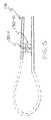
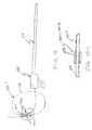
- FIG. 8is a diagrammatic illustration of a guidewire including an embodiment of a magnetic clamp of the present invention.
- FIG. 9is a diagrammatic illustration of the guidewire of FIG. 8 secured in a coiled configuration by the magnetic clamp of the present invention.
- FIGS. 10-1 through 10 - 3are illustrations of various embodiments of clamp members on a segment of the guidewire.
- FIG. 11is a diagrammatic illustration of a guidewire including multiple spaced clamp members along a length thereof.
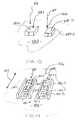
- FIG. 12is an illustration of an embodiment of a magnetic clamp device including a table supporting clamp members.
- FIG. 13is an illustration of an embodiment of clamp members on the table illustrated in FIG. 12 .
- FIG. 14is an illustration of an embodiment of clamp members on the table illustrated in FIG. 12 .
- FIG. 15is a detailed illustration of the clamp members of FIG. 14 including magnets having alternating polarity.
- FIG. 16is an illustration of an embodiment of a magnetic clamp device incorporated with a magnetic captivation tool for facilitating a catheter exchange.
- the present inventiongenerally relates to elongated flexible devices inserted-into a body lumen or vessel for treatment.
- Such devicesare formed of a biocompatible material and are typically packaged in a sterile condition. Once devices are removed from the sterile packaging, it is important that the devices remain in a sterile environment for use. If the devices become contaminated prior to use or reuse, the device may need to be discarded which can increase the cost of treatment and possibly delay treatment.
- FIG. 1illustrates embodiments of coronary angioplasty devices for treating a lesion 100 in a coronary vessel 102 .
- angioplasty treatment devicesinclude a guide catheter 106 .
- the guide catheter 106is formed of a flexible tubular member having an elongated length extending from a proximal manifold 108 to a distal end 110 .
- the guide catheteris inserted into a vascular lumen 112 at a femoral artery and advanced until the distal end 110 of the guide catheter 106 is adjacent a mouth of the coronary vessel 102 .
- the inserted guide catheter 106provides a conduit for inserting a treatment catheter 114 or diagnostic catheter.
- treatment catheter 114is an over-the-wire balloon catheter.
- the balloon catheterincludes a flexible catheter shaft 116 having an elongated length extending between a proximal end and a distal end.
- a dilatation balloon 118is supported at the distal end of the catheter shaft 116 and the catheter shaft 116 includes a proximal manifold 120 .
- an elongated flexible guidewire 122extends through a guidewire lumen (not shown) in shaft 116 to facilitate placement of the treatment catheter 114 as will be explained.
- an inflation device 123is coupled to an inflation lumen (not shown) at proximal manifold 120 to inflate balloon 118 .
- the length of the catheter shaft 116is sufficiently long to extend from the femoral artery to the treatment vessel 102 .
- the length of guidewire 122is longer than shaft 116 so that a proximal portion 124 extends beyond the proximal manifold 120 (beyond the guidewire lumen in shaft 116 ) for gripping the guidewire 122 for use.
- the guidewire 122extends along shaft 116 and includes a distal portion 126 which extends distally beyond shaft 116 to track the balloon 118 (or other treatment device) across the lesion.
- the length of an angioplasty catheteris approximately 150 cm long and a guidewire 122 is approximately 175 cm long.
- catheter 114is advanced through guide catheter 106 , with the guidewire 122 extending through the catheter shaft 116 , to the distal end of the guide catheter 106 .
- Guidewire 122is independently advanced into the restricted coronary vessel 102 to cross the lesion 100 .
- Guidewire 122is independently advanced by manipulating the proximal portion 124 of the guidewire 122 extending outside the proximal manifold 120 .
- catheter shaft 116is advanced along guidewire 122 to position the balloon 118 (or other treatment device) across the lesion 100 .
- the devicemust be kept sterile for insertion into a body vessel or lumen.
- devicesmay be temporarily withdrawn or removed. Temporarily withdrawn devices or catheters must be kept sterile for reuse.
- a surgeon or doctormay be using or handling multiple devices and the length of such devices can make it difficult to manage or control the devices so that the entire length of every device is maintained within the sterile field for the entire procedure.
- FIGS. 2-3illustrate a treatment catheter 114 - 1 incorporating a magnetic clamp 128 for coiling or collapsing an extent of the elongated length of flexible shaft 116 where like numbers are used to identify like parts in the previous FIG.
- the clamp device 128includes magnetically attracted clamp members 130 - 1 , 130 - 2 illustrated diagrammatically in FIGS. 2-3.
- clamp member 130 - 1is formed along a first portion 132 - 1 of the catheter shaft 116 and clamp member 130 - 2 is formed along a second portion 132 - 2 of the catheter shaft 116 spaced from clamp member 130 - 1 .
- the magnetically attracted clamp members 130 - 1 , 130 - 2are spaced to cooperatively form the magnetic clamp 128 as illustrated in FIG. 3 .
- the magnetic clamp 128secures a segment of the catheter shaft 116 in a coiled configuration to collapse an extended length of the catheter shaft so that the catheter is more compact and thus, easy to control and maintain in the sterile field.
- the magnetic attraction between the clamp members 130 - 1 , 130 - 2is designed to secure or clamp the shaft 116 in the coiled configuration yet allow the clamp members 130 - 1 , 130 - 2 to easily separate to release the catheter shaft 116 from its coiled configuration.
- the magnetic clamp device describedcan be easily operated to clamp the catheter shaft 116 in a coiled configuration and easily released to straighten the catheter shaft 116 for use.
- clamp member 130 - 1is positioned midshaft and clamp member 130 - 2 is positioned proximate to proximal manifold 120 to coil the catheter for sterile use.
- Clamp members 130 - 1 , 130 - 2can be positioned at alternate locations to coil various portions of the catheter shaft 116 and to connect the shaft 116 in alternate collapsed profiles, such as in a looped profile as illustrated in FIG. 4 .
- the magnetically attracted clamp members 130 - 1 , 130 - 2can be formed of a magnetically responsive material and a magnetically active material.
- a magnetically active materialis a material having a magnetic field, such as a permanent magnet or electromagnet.
- a magnetically responsive materialis a material which is attracted to a magnetically active material.
- the proximal clamp member 130 - 2is formed of a magnetically active material and the midshaft (or distal) clamp member 130 - 1 is formed of a magnetically responsive material so that the magnetically active material remains outside the patient during treatment.
- An example of a magnetically active materialincludes a neodymium magnet and examples of a magnetically responsive material include a vanadium permedur material, Hyperco®, or other ferromagnetic material.
- the magnetically active material or magnetically responsive materialcan be a solid magnet or ferromagnet or magnetic particles can be embedded in a polymer base material to form the active magnet or responsive magnetic material.
- both clamp members 130 - 1 , 130 - 2can be formed of magnetically active material, as illustrated schematically in FIG. 5, in which a magnetic pole of clamp member 130 - 1 is attracted toward the opposite magnetic pole of clamp 130 - 2 .
- the clamp members 130 - 1 , 130 - 2are magnetically attracted to selectively clamp portions of the flexible catheter shaft 116 as previously described.
- FIGS. 6-1 through 6 - 3illustrate alternate embodiments of clamp members 130 formed on a portion of the flexible shaft 116 .
- Flexible shaft 116is typically formed of a polymer material.
- clamp members 130are formed of an annular ring or tube 140 of a magnetically active or magnetically responsive material.
- ring 140extends about an outer perimeter 141 of shaft 116 .
- ring 140is seated in an outer recess 142 about perimeter 141 of catheter shaft 116 to provide a smooth profile for the catheter shaft 116 .
- FIG. 6-2ring 140 is seated in an outer recess 142 about perimeter 141 of catheter shaft 116 to provide a smooth profile for the catheter shaft 116 .
- clamp 140is seated in an inner recess 144 surrounding a lumen 146 along shaft 116 .
- Clamp members 130can be formed in a proximal strain relief (not shown) or manifold 120 .
- clamp members 130 - 1 , 130 - 2can be formed separately from shaft 116 and fastened or clipped to the catheter shaft 116 for use.
- clamp members 130 - 1 , 130 - 2can be fastened to shaft 116 when the catheter is prepared for use and remain on the shaft 116 for use as necessary.
- clamps 130 - 1 , 130 - 2 , 130 -ncan be spaced along the catheter shaft 116 to provide flexibility for coiling or collapsing the catheter shaft 116 in different configurations.
- clamps 130 - 1 , 130 - 2 , 130 -ncan be formed of a magnetically active material.
- a proximal clamp member 130 - 1can be formed of a magnetically active material and distal clamp members 130 - 2 to 130 -n can be formed of a magnetically responsive material.
- magnetically active or responsive clamp memberscan be intermittently dispersed along portions of the catheter shaft 116 .
- the magnetic clampis easily operable to retain the elongated shaft 116 in a collapsed profile and application is not limited to the particular configurations shown.
- the catheter 114be withdrawn over an inserted guidewire so that the guidewire remains in place across the stenosis 100 to advance the next catheter across the stenosis 100 for treatment.
- a proximal portion of the guidewire which is external to the patientmust be exposed at all times while the catheter 114 is withdrawn so that the operator can grip the guidewire to control the position of the guidewire relative to the stenosis.
- the guidewire 122extends through a guidewire lumen which is longer than the proximal portion of the guidewire external to the patient.
- exchange length guidewire 122 - 1a longer exchange guidewire or guidewire extension
- an exchange wirehaving a length of about 300 cm or a guide wire extension having a length about 125-150 cm can be used.
- the additional length of the exchange guidewire or extensionprovides an external guidewire portion which is longer than the length of the guidewire lumen of the inserted catheter to allow the physician to grip the inserted guidewire 122 - 1 while the catheter 114 is removed over the guidewire 122 - 1 .
- the long length of the exchange length guidewire 122 - 1makes it difficult to maintain the entire length of the guidewire 112 - 1 in the sterile field during treatment.
- FIGS. 8-10illustrate alternate embodiments of a magnetic clamp device for collapsing a proximal length of the exchange length guidewire 122 - 1 so that it remains in the sterile field during treatment where like numbers are used to refer to like parts in the previous FIGS.
- a proximal length 148 of the exchange length guidewire 122 - 1 extending beyond the proximal end of the catheter shaft 116 and outside the patientincludes clamp members 150 - 1 , 150 - 2 illustrated diagrammatically which cooperatively form clamp 152 as shown in FIG. 9 .
- Clamp member 150 - 1is formed along a first portion of the guidewire 122 - 1 and the second clamp member 150 - 2 is formed along a second portion of the guidewire 122 - 1 spaced from clamp member 150 - 1 as shown.
- the clamp members 150 - 1 , 150 - 2are spaced to cooperatively form magnetic clamp 152 to retain the proximal length 148 of the guidewire 122 - 1 in a coiled or collapsed profile as shown in FIG. 9 .
- Clamp members 150 - 1 , 150 - 2can be active magnets or alternatively, clamp members 150 - 1 , 150 - 2 can include an active magnet and a magnetically responsive segment as previously described for clamp members 130 - 1 , 130 - 2 .
- FIGS. 10-1 through 10 - 3illustrate alternate embodiments for clamp members 150 - 1 , 150 - 2 formed along the proximal length of guidewire 122 - 1 .
- Clamp members 150 - 1 , 150 - 2can be formed of an annular ring 153 extending about an outer perimeter. 154 of guidewire 122 - 1 as shown in FIG. 10-1 or an annular ring 156 seated in recess 158 extending about perimeter 154 of the guidewire 122 - 1 as shown in FIG. 10-2.
- portions of the guidewire 122 - 1can be formed of a magnetic segment 160 adhesively connected to guidewire segments 162 - 1 , 162 - 2 to form guidewire 122 - 1 .
- Annular rings 153 , 156 or magnetic segment 160can be formed of an active magnet or a magnetically responsive material such as a Hyperco®.
- clamp member 150 - 1is an active magnet and clamp member 150 - 2 is a magnetically responsive segment.
- multiple clamp members 150 - 1 , 150 - 2 , 150 -nextend along the proximal length of the exchange length guidewire 122 - 1 as illustrated in FIG. 11 to coil different lengths of the guidewire 122 - 1 .
- Multiple clamp members 150 - 1 , 150 - 2 , 150 -ncan include an active magnet and a plurality of magnetically responsive segments spaced from the active magnet to retain guidewire 122 - 1 in a coiled profile as illustrated in FIG. 9 or other collapsed profiles (not shown).
- FIG. 12illustrates another embodiment of a magnetic clamp device for securing a medical device prior to, during or subsequent to treatment.
- the deviceincludes a table or tray 166 including magnetic clamp members 168 - 1 , 168 - 2 , 168 -n (illustrated schematically) which cooperate with clamp members 170 - 1 , 170 - 2 (illustrated schematically) on treatment devices 172 - 1 , 172 - 2 as shown.
- Clamp members 138 and 170magnetically attract or couple to secure the treatment device or catheter 172 relative to table 166 .
- Clamp members 168 , 170can be formed of an active magnet or a magnetically responsive material.
- clamp members 170are formed of a magnetically responsive material and clamp members 168 are active magnets, although application is not limited to any specific embodiment shown.
- the table 166may be sterile or covered with a sterile drape (not shown) so that treatment devices are maintained or stored in a sterile environment or field for use during treatment.
- Treatment devices 172can include syringes, guidewires, catheters, guide catheters, grips, Y-adapters, stents, rotablator and other treatment devices and any number of clamp members 168 can be supported on table 166 to secure multiple treatment devices or a single treatment device.
- table 166includes base rails 176 - 1 , 176 - 2 along a length thereof separated by channel 178 which are contoured to rest on a patient's chest or abdomen or over a leg of a patient.
- rails 176 - 1 , 176 - 2extend along an entire length of table 166 although application is not limited to the specific embodiment shown.
- FIGS. 13-14illustrate alternate clamping embodiments for clamp members 168 .
- clamp members 168include active magnets 180 - 1 , 180 - 2 arranged to magnetically attract responsive segments on a treatment device 172 .
- poles N,S of active magnets 180 - 1 , 180 - 2are orientated so that the flux path is perpendicular to surface 182 of table 166 .
- the perpendicular orientation of the flux path and poles N, Sprovides a relatively strong attractive force between the active magnets 180 and magnetically responsive segments on the treatment device in a downward direction toward surface 182 of table 166 as illustrated by arrows 184 .
- the treatment deviceincludes multiple spaced clamp members 170 - 1 , 170 - 2 (as shown in FIG. 12) formed of magnetically responsive segments.
- the spaced clamp members 170 - 1 , 170 - 2can be magnetically attracted to a single active magnet 180 - 1 on table 116 to secure spaced portions of the treatment device relative to table 166 or alternatively, spaced clamp members 170 - 1 , 170 - 2 can be secured to multiple active magnets 180 - 1 , 180 - 2 to clamp an elongated portion of a treatment device to table 166 in a coiled or collapsed profile.
- a single clamp member 170 on treatment devicecan be secured to a single active magnet clamp member 180 - 1 or 180 - 2 on table 166 .
- FIGS. 14-15illustrates an alternate clamping embodiment for clamp members 168 supported on table 166 .
- each clamp member 168 - 1 , 168 - 2can include a plurality of spaced active magnet segments 186 - 1 , 186 - 2 , 186 - 3 having alternating polarity.
- the active magnet segments 186 - 1 , 186 - 2 , 186 - 3are arranged in a slot or channel 188 formed between extending walls 190 - 1 , 190 - 2 .
- Magnet segments 186 - 1 , 186 - 2 , 186 - 3are arranged so that poles N,S are orientated so that the flux path and poles are essentially parallel to table surface 182 . As shown, magnet segments 186 - 1 , 186 - 2 , 186 - 3 are arranged with alternating polarity. For example, in the embodiment shown, magnet segments 186 - 1 , 186 - 3 nave a first polarity or pole orientation and magnet segment 186 - 2 has a second opposite polarity or pole orientation to secure a treatment device 172 relative to table 166 as will be described.
- clamp members 170 - 1 , 170 - 2 , 170 - 3 on treatment devices 172are formed of magnetically responsive segments spaced similar to active magnets 186 - 1 , 186 - 2 , 186 - 3 .
- Responsive segments. 170 - 1 , 170 - 2 , 170 - 3 on the treatment deviceare formed of a magnetically permeable material capable of being magnetized.
- the interaction of the active magnets 186 - 1 , 186 - 2 , 186 - 3 with the magnetically responsive segments 170 - 1 , 170 - 2 , 170 - 3 on the treatment deviceprovides a flux path through segments 170 - 1 , 170 - 2 , 170 - 3 to attract segments 170 - 1 , 170 - 2 , 170 - 3 toward active magnets 186 - 1 , 186 - 2 , 186 - 3 .
- the alternating polarity of the active magnets 186 - 1 , 186 - 2 , 186 - 3provide a longitudinal restrictive force in a direction illustrated by arrow 192 as shown in FIG. 15 .
- movement of segments 170 - 1 , 170 - 2 , 170 - 3is restricted due to the opposite polarity of magnets 186 - 1 , 186 - 2 , 186 - 3 .
- a portion of an elongated treatment deviceis coiled or collapsed and the collapsed portion is inserted into slot 188 with the magnetically responsive segments on the treatment device aligned with the active magnet segments 186 - 1 , 186 - 2 , 186 - 3 to retain the device in a collapsed profile during treatment.
- magnet segments 186 - 1 , 186 - 2 , 186 - 3are aligned along a longitudinally extending axis in a longitudinally aligned slot 188 formed between longitudinally aligned walls 190 - 1 , 190 - 2 .
- longitudinal alignmentis shown, application is not limited to the longitudinal alignment shown.
- magnet segments 186 - 1 , 186 - 2 , 186 - 3can be spaced along a curved axis (not shown).
- FIGS. 13-14illustrate specific embodiment and pattern of clamp members 168 , application is not limited to the specific embodiments or patterns shown.
- Magnetic captivation tools 200have been developed to facilitate a catheter exchange for an over-the-wire catheter without use of an exchange length guidewire 122 - 1 so that a standard length guidewire can be used.
- Such tools 200include a plurality of active magnets 202 (illustrated diagrammatically in FIG. 16) coupled along an elongated channel. Magnetically responsive segments are formed along a proximal length of guidewire and are spaced similar to the spacing between magnets 202 .
- active magnets 202are spaced with alternating polarity as previously described with reference to FIG. 15 to secure guidewire relative to the captivation tool by the interaction between the plurality of magnets 202 and the magnetically responsive segments on the guidewire.
- a proximal portion of guidewire 122 - 2is inserted through the channel of the captivation tool 200 so that the magnetically responsive segments are aligned with the magnets 202 on the tool 200 to hold the guidewire in place and restrict longitudinal movement of the guidewire 122 - 2 as previously described in reference to FIG. 15 .
- catheter 114is withdrawn over the secured guide wire 122 - 2 through the channel of the captivation tool 200 having magnets 202 holding the guidewire 122 in place.
- the captivation tool 200 - 1 of the present inventionincorporates a clamp for collapsing a length of guidewire 122 - 2 as illustrated in FIG. 16 .
- tool 200 - 1includes multiple spaced magnetic captivation segments 204 - 1 , 204 - 2 each including a plurality of magnets 202 - 1 , 202 - 2 of alternating polarity which form multiple clamp segments and the guidewire 122 - 2 includes multiple spaced magnetically responsive segments (not shown) or clamp members spaced to align with multiple captivation segments 204 - 1 , 204 - 2 in a collapsed or coiled profile.
- captivation segments 204 - 1 , 204 - 2are oriented to engage spaced magnetically responsive segments on the guidewire 122 - 2 to connect guidewire 122 - 2 in a coiled or looped profile as shown.
- captivation segments 204 - 1 , 204 - 2can be formed on opposed sides or faces of an integral tool block 206 forming the captivation tool as illustrated diagrammatically in FIG. 16 or spaced on a single face of a tool block 206 .
- Captivation segmentscan be formed on faces of multiple tool blocks (not shown) which are connected to form the captivation tool having multiple spaced captivation segments 204 - 1 , 204 - 2 .
- multiple spaced captivation segments 204 - 1 , 204 - 2can be formed on a planar surface of a table, such as the table illustrated in FIGS. 12-14. Although a particular coiled arrangement is shown, application is not limited to the particular arrangement shown.
Landscapes
- Health & Medical Sciences (AREA)
- Life Sciences & Earth Sciences (AREA)
- Biophysics (AREA)
- Pulmonology (AREA)
- Engineering & Computer Science (AREA)
- Anesthesiology (AREA)
- Biomedical Technology (AREA)
- Heart & Thoracic Surgery (AREA)
- Hematology (AREA)
- Animal Behavior & Ethology (AREA)
- General Health & Medical Sciences (AREA)
- Public Health (AREA)
- Veterinary Medicine (AREA)
- Media Introduction/Drainage Providing Device (AREA)
Abstract
Description
The present invention relates to the field of medical devices such as elongated flexible catheter and accessory devices. In particular, the present invention relates to a magnetic clamp assembly for retaining elongated flexible medical devices in a coiled or collapsed condition and has particular application for angioplasty devices.
Catheter and other treatment devices are formed of elongated members which are relatively flexible for insertion into a body vessel of a patient for treatment. The length of various catheter or treatment devices is relatively long to track the device to a remote treatment site. For example, typically the length of an angioplasty catheter is approximately 150 cm long and a guidewire is approximately 175 cm long. Catheter and other treatment devices are sterilized for human use.
Prior to use and reuse, the catheter or other device must remain in a sterile zone or field. The extended length of catheters and other treatment devices are packaged in sterile containers in a coiled configuration. Once removed from the sterile packaging, the entire length of the device must remain in the sterile field for use and reuse. The sterile zone or field is typically a sterile cart, operating table or localized treatment area. The long length of catheters or other devices makes it awkward to control and handle the device and retain the device in the sterile field.
Angioplasty devices are intravascularly inserted into a patient for treating coronary heart disease. Angioplasty devices include an elongated catheter having a dilation balloon supported at a distal end which is inserted over an elongated guidewire. During an angioplasty procedure, often several different types of catheters are employed sequentially utilizing the same guidewire and in some cases the catheter may be alternately used several times. Once removed from the guidewire, the catheter must be kept in a sterile field for re-use. As previously discussed, the length of the catheter shaft makes it quite awkward and inconvenient to retain the catheter in the sterile field for reuse.
Various types of catheter devices used include fixed wire catheters, over-the-wire catheters and single operator exchange catheters. During an angioplasty procedure, a doctor may decide to exchange an inserted catheter device with another catheter device. To facilitate a catheter exchange with an over-the-wire catheter device, a guidewire extension can be added to the end of the guidewire or an original wire can be replaced with an exchange guidewire. It is important to assure that the length of guidewire extension or exchange guidewire remains sterile and does not drop on the floor. However, the additional length of the guidewire extension or exchange guidewire makes it difficult to retain the length of the guidewire in the sterile field.
Prior mechanical clip devices are known to retain elongated catheters in a coiled configuration for use and reuse. These devices can be cumbersome to use and can require two hands to operate. The present invention address these and other problems and has wide application for various angioplasty catheter devices such as cutting devices, fiber optic catheters, ultrasound probes and other treatment devices.
The present invention relates to a magnetic clamp assembly for an elongated flexible medical device or treatment device. The clamp assembly includes magnetic clamp members operably coupled to clamp a portion of the flexible medical device to secure the medical device during treatment.
FIG. 1 is an illustration of an angioplasty catheter system in a vascular lumen of a patient.
FIG. 2 is a diagrammatic illustration of a catheter including an embodiment of a magnetic clamp of the present invention.
FIG. 3 is a diagrammatic illustration of the catheter of FIG. 2 secured in a coiled configuration by the magnetic clamp of the present invention.
FIG. 4 is a diagrammatic illustration of the catheter of FIG. 2 secured in a looped configuration by the magnetic clamp of the present invention.
FIG. 5 is a diagrammatic illustration of an embodiment of clamp members of a magnetic clamp of the present invention.
FIGS. 6-1 through6-3 are cross-sectional views of various embodiments of clamp members coupled to a segment of the catheter.
FIG. 7 is a diagrammatic illustration of a catheter including multiple spaced clamp members along a length thereof.
FIG. 8 is a diagrammatic illustration of a guidewire including an embodiment of a magnetic clamp of the present invention.
FIG. 9 is a diagrammatic illustration of the guidewire of FIG. 8 secured in a coiled configuration by the magnetic clamp of the present invention.
FIGS. 10-1 through10-3 are illustrations of various embodiments of clamp members on a segment of the guidewire.
FIG. 11 is a diagrammatic illustration of a guidewire including multiple spaced clamp members along a length thereof.
FIG. 12 is an illustration of an embodiment of a magnetic clamp device including a table supporting clamp members.
FIG. 13 is an illustration of an embodiment of clamp members on the table illustrated in FIG.12.
FIG. 14 is an illustration of an embodiment of clamp members on the table illustrated in FIG.12.
FIG. 15 is a detailed illustration of the clamp members of FIG. 14 including magnets having alternating polarity.
FIG. 16 is an illustration of an embodiment of a magnetic clamp device incorporated with a magnetic captivation tool for facilitating a catheter exchange.
The present invention generally relates to elongated flexible devices inserted-into a body lumen or vessel for treatment. Such devices are formed of a biocompatible material and are typically packaged in a sterile condition. Once devices are removed from the sterile packaging, it is important that the devices remain in a sterile environment for use. If the devices become contaminated prior to use or reuse, the device may need to be discarded which can increase the cost of treatment and possibly delay treatment.
Angioplasty devices are used to treat heart disease. FIG. 1 illustrates embodiments of coronary angioplasty devices for treating alesion 100 in acoronary vessel 102. As shown, angioplasty treatment devices include aguide catheter 106. Theguide catheter 106 is formed of a flexible tubular member having an elongated length extending from aproximal manifold 108 to adistal end 110. The guide catheter is inserted into a vascular lumen112 at a femoral artery and advanced until thedistal end 110 of theguide catheter 106 is adjacent a mouth of thecoronary vessel 102. The insertedguide catheter 106 provides a conduit for inserting atreatment catheter 114 or diagnostic catheter.
As shown in FIG. 1,treatment catheter 114 is an over-the-wire balloon catheter. The balloon catheter includes aflexible catheter shaft 116 having an elongated length extending between a proximal end and a distal end. Adilatation balloon 118 is supported at the distal end of thecatheter shaft 116 and thecatheter shaft 116 includes aproximal manifold 120. As shown, an elongatedflexible guidewire 122 extends through a guidewire lumen (not shown) inshaft 116 to facilitate placement of thetreatment catheter 114 as will be explained. For dilatation, aninflation device 123 is coupled to an inflation lumen (not shown) atproximal manifold 120 to inflateballoon 118.
The length of thecatheter shaft 116 is sufficiently long to extend from the femoral artery to thetreatment vessel 102. The length ofguidewire 122 is longer thanshaft 116 so that aproximal portion 124 extends beyond the proximal manifold120 (beyond the guidewire lumen in shaft116) for gripping theguidewire 122 for use. Theguidewire 122 extends alongshaft 116 and includes adistal portion 126 which extends distally beyondshaft 116 to track the balloon118 (or other treatment device) across the lesion. Typically the length of an angioplasty catheter is approximately 150 cm long and aguidewire 122 is approximately 175 cm long.
For treatment,catheter 114 is advanced throughguide catheter 106, with theguidewire 122 extending through thecatheter shaft 116, to the distal end of theguide catheter 106.Guidewire 122 is independently advanced into the restrictedcoronary vessel 102 to cross thelesion 100.Guidewire 122 is independently advanced by manipulating theproximal portion 124 of theguidewire 122 extending outside theproximal manifold 120. Thereafter,catheter shaft 116 is advanced alongguidewire 122 to position the balloon118 (or other treatment device) across thelesion 100.
As previously, described, for use, the device must be kept sterile for insertion into a body vessel or lumen. During treatment, devices may be temporarily withdrawn or removed. Temporarily withdrawn devices or catheters must be kept sterile for reuse. During a treatment procedure, a surgeon or doctor may be using or handling multiple devices and the length of such devices can make it difficult to manage or control the devices so that the entire length of every device is maintained within the sterile field for the entire procedure.
FIGS. 2-3 illustrate a treatment catheter114-1 incorporating amagnetic clamp 128 for coiling or collapsing an extent of the elongated length offlexible shaft 116 where like numbers are used to identify like parts in the previous FIG. As shown in FIG. 2, theclamp device 128 includes magnetically attracted clamp members130-1,130-2 illustrated diagrammatically in FIGS. 2-3. As shown in FIG. 2, clamp member130-1 is formed along a first portion132-1 of thecatheter shaft 116 and clamp member130-2 is formed along a second portion132-2 of thecatheter shaft 116 spaced from clamp member130-1. The magnetically attracted clamp members130-1,130-2 are spaced to cooperatively form themagnetic clamp 128 as illustrated in FIG.3.
As shown in FIG. 3, themagnetic clamp 128 secures a segment of thecatheter shaft 116 in a coiled configuration to collapse an extended length of the catheter shaft so that the catheter is more compact and thus, easy to control and maintain in the sterile field. The magnetic attraction between the clamp members130-1,130-2 is designed to secure or clamp theshaft 116 in the coiled configuration yet allow the clamp members130-1,130-2 to easily separate to release thecatheter shaft 116 from its coiled configuration. Thus, the magnetic clamp device described can be easily operated to clamp thecatheter shaft 116 in a coiled configuration and easily released to straighten thecatheter shaft 116 for use.
In the embodiment shown, clamp member130-1 is positioned midshaft and clamp member130-2 is positioned proximate toproximal manifold 120 to coil the catheter for sterile use. Clamp members130-1,130-2 can be positioned at alternate locations to coil various portions of thecatheter shaft 116 and to connect theshaft 116 in alternate collapsed profiles, such as in a looped profile as illustrated in FIG.4.
The magnetically attracted clamp members130-1,130-2 can be formed of a magnetically responsive material and a magnetically active material. A magnetically active material is a material having a magnetic field, such as a permanent magnet or electromagnet. A magnetically responsive material is a material which is attracted to a magnetically active material. In one embodiment, having a proximal clamp member130-2, and a midshaft (or distal) clamp member130-1, the proximal clamp member130-2 is formed of a magnetically active material and the midshaft (or distal) clamp member130-1 is formed of a magnetically responsive material so that the magnetically active material remains outside the patient during treatment.
An example of a magnetically active material includes a neodymium magnet and examples of a magnetically responsive material include a vanadium permedur material, Hyperco®, or other ferromagnetic material. The magnetically active material or magnetically responsive material can be a solid magnet or ferromagnet or magnetic particles can be embedded in a polymer base material to form the active magnet or responsive magnetic material. Alternatively, both clamp members130-1,130-2 can be formed of magnetically active material, as illustrated schematically in FIG. 5, in which a magnetic pole of clamp member130-1 is attracted toward the opposite magnetic pole of clamp130-2. The clamp members130-1,130-2 are magnetically attracted to selectively clamp portions of theflexible catheter shaft 116 as previously described.
The clamp members130-1,130-2 can be connected to or formed withshaft 116 ormanifold 120. FIGS. 6-1 through6-3 illustrate alternate embodiments ofclamp members 130 formed on a portion of theflexible shaft 116.Flexible shaft 116 is typically formed of a polymer material. In the illustrated embodiments,clamp members 130 are formed of an annular ring ortube 140 of a magnetically active or magnetically responsive material. In the embodiment of FIG. 6-1,ring 140 extends about anouter perimeter 141 ofshaft 116. In FIG. 6-2,ring 140 is seated in anouter recess 142 aboutperimeter 141 ofcatheter shaft 116 to provide a smooth profile for thecatheter shaft 116. In FIG. 6-3,ring 140 is seated in aninner recess 144 surrounding alumen 146 alongshaft 116.Clamp members 130 can be formed in a proximal strain relief (not shown) ormanifold 120. Alternatively, clamp members130-1,130-2 can be formed separately fromshaft 116 and fastened or clipped to thecatheter shaft 116 for use. For example, clamp members130-1,130-2 can be fastened toshaft 116 when the catheter is prepared for use and remain on theshaft 116 for use as necessary.
As illustrated in FIG. 7, multiple spaced clamp members130-1,130-2,130-n can be spaced along thecatheter shaft 116 to provide flexibility for coiling or collapsing thecatheter shaft 116 in different configurations. As previously described, clamps130-1,130-2,130-n can be formed of a magnetically active material. In one embodiment, a proximal clamp member130-1 can be formed of a magnetically active material and distal clamp members130-2 to130-n can be formed of a magnetically responsive material. Alternatively, magnetically active or responsive clamp members can be intermittently dispersed along portions of thecatheter shaft 116. Thus, as described, the magnetic clamp is easily operable to retain theelongated shaft 116 in a collapsed profile and application is not limited to the particular configurations shown.
Often times, it is desirable to exchange onecatheter 114 for another catheter during a treatment procedure. It is usually preferred that thecatheter 114 be withdrawn over an inserted guidewire so that the guidewire remains in place across thestenosis 100 to advance the next catheter across thestenosis 100 for treatment. During the exchange, a proximal portion of the guidewire which is external to the patient must be exposed at all times while thecatheter 114 is withdrawn so that the operator can grip the guidewire to control the position of the guidewire relative to the stenosis. However, in an over-the-wire catheter, theguidewire 122 extends through a guidewire lumen which is longer than the proximal portion of the guidewire external to the patient. Thus, if the physician were to fully withdraw the catheter while leaving the guidewire in place, thecatheter 114 would completely cover the external portion of theguidewire 122 and the surgeon or doctor would not be able to grip the guidewire during the exchange.
Thus, a longer exchange guidewire or guidewire extension (hereinafter, exchange length guidewire122-1) can be used to maintain control of the guidewire during the exchange process. For example, an exchange wire, having a length of about 300 cm or a guide wire extension having a length about 125-150 cm can be used. The additional length of the exchange guidewire or extension provides an external guidewire portion which is longer than the length of the guidewire lumen of the inserted catheter to allow the physician to grip the inserted guidewire122-1 while thecatheter 114 is removed over the guidewire122-1. The long length of the exchange length guidewire122-1, however, makes it difficult to maintain the entire length of the guidewire112-1 in the sterile field during treatment.
FIGS. 8-10 illustrate alternate embodiments of a magnetic clamp device for collapsing a proximal length of the exchange length guidewire122-1 so that it remains in the sterile field during treatment where like numbers are used to refer to like parts in the previous FIGS. As shown in FIG. 8, aproximal length 148 of the exchange length guidewire122-1 extending beyond the proximal end of thecatheter shaft 116 and outside the patient includes clamp members150-1,150-2 illustrated diagrammatically which cooperatively formclamp 152 as shown in FIG.9. Clamp member150-1 is formed along a first portion of the guidewire122-1 and the second clamp member150-2 is formed along a second portion of the guidewire122-1 spaced from clamp member150-1 as shown. The clamp members150-1,150-2 are spaced to cooperatively formmagnetic clamp 152 to retain theproximal length 148 of the guidewire122-1 in a coiled or collapsed profile as shown in FIG.9. Clamp members150-1,150-2 can be active magnets or alternatively, clamp members150-1,150-2 can include an active magnet and a magnetically responsive segment as previously described for clamp members130-1,130-2.
FIGS. 10-1 through10-3 illustrate alternate embodiments for clamp members150-1,150-2 formed along the proximal length of guidewire122-1. Clamp members150-1,150-2 can be formed of anannular ring 153 extending about an outer perimeter.154 of guidewire122-1 as shown in FIG. 10-1 or an annular ring156 seated inrecess 158 extending aboutperimeter 154 of the guidewire122-1 as shown in FIG. 10-2. Alternatively, as shown in FIG. 10-3, portions of the guidewire122-1 can be formed of a magnetic segment160 adhesively connected to guidewire segments162-1,162-2 to form guidewire122-1. Annular rings153,156 or magnetic segment160 can be formed of an active magnet or a magnetically responsive material such as a Hyperco®. In one embodiment, clamp member150-1 is an active magnet and clamp member150-2 is a magnetically responsive segment.
In an alternate embodiment, multiple clamp members150-1,150-2,150-n extend along the proximal length of the exchange length guidewire122-1 as illustrated in FIG. 11 to coil different lengths of the guidewire122-1. Multiple clamp members150-1,150-2,150-n can include an active magnet and a plurality of magnetically responsive segments spaced from the active magnet to retain guidewire122-1 in a coiled profile as illustrated in FIG. 9 or other collapsed profiles (not shown).
FIG. 12 illustrates another embodiment of a magnetic clamp device for securing a medical device prior to, during or subsequent to treatment. The device includes a table ortray 166 including magnetic clamp members168-1,168-2,168-n (illustrated schematically) which cooperate with clamp members170-1,170-2 (illustrated schematically) on treatment devices172-1,172-2 as shown. Clamp members138 and170 magnetically attract or couple to secure the treatment device orcatheter 172 relative to table166.Clamp members 168,170 can be formed of an active magnet or a magnetically responsive material. In one embodiment, clamp members170 are formed of a magnetically responsive material and clampmembers 168 are active magnets, although application is not limited to any specific embodiment shown.
The table166 may be sterile or covered with a sterile drape (not shown) so that treatment devices are maintained or stored in a sterile environment or field for use during treatment.Treatment devices 172 can include syringes, guidewires, catheters, guide catheters, grips, Y-adapters, stents, rotablator and other treatment devices and any number ofclamp members 168 can be supported on table166 to secure multiple treatment devices or a single treatment device.
In the embodiment illustrated in FIG. 12, table166 includes base rails176-1,176-2 along a length thereof separated bychannel 178 which are contoured to rest on a patient's chest or abdomen or over a leg of a patient. In the embodiment shown, rails176-1,176-2 extend along an entire length of table166 although application is not limited to the specific embodiment shown.
FIGS. 13-14 illustrate alternate clamping embodiments forclamp members 168. As shown in FIG. 13,clamp members 168 include active magnets180-1,180-2 arranged to magnetically attract responsive segments on atreatment device 172. As shown, poles N,S of active magnets180-1,180-2 are orientated so that the flux path is perpendicular to surface182 of table166. The perpendicular orientation of the flux path and poles N, S provides a relatively strong attractive force between the active magnets180 and magnetically responsive segments on the treatment device in a downward direction towardsurface 182 of table166 as illustrated byarrows 184.
In one embodiment, the treatment device includes multiple spaced clamp members170-1,170-2 (as shown in FIG. 12) formed of magnetically responsive segments. The spaced clamp members170-1,170-2 can be magnetically attracted to a single active magnet180-1 on table116 to secure spaced portions of the treatment device relative to table166 or alternatively, spaced clamp members170-1,170-2 can be secured to multiple active magnets180-1,180-2 to clamp an elongated portion of a treatment device to table166 in a coiled or collapsed profile. Alternatively, a single clamp member170 on treatment device can be secured to a single active magnet clamp member180-1 or180-2 on table166.
FIGS. 14-15 illustrates an alternate clamping embodiment forclamp members 168 supported on table166. In the embodiment shown in FIGS. 14-15, each clamp member168-1,168-2 can include a plurality of spaced active magnet segments186-1,186-2,186-3 having alternating polarity. In the embodiment shown in FIG. 14, the active magnet segments186-1,186-2,186-3 are arranged in a slot orchannel 188 formed between extending walls190-1,190-2. Magnet segments186-1,186-2,186-3 are arranged so that poles N,S are orientated so that the flux path and poles are essentially parallel totable surface 182. As shown, magnet segments186-1,186-2,186-3 are arranged with alternating polarity. For example, in the embodiment shown, magnet segments186-1,186-3 nave a first polarity or pole orientation and magnet segment186-2 has a second opposite polarity or pole orientation to secure atreatment device 172 relative to table166 as will be described.
For operation of the embodiment illustrated in FIGS. 14-15, clamp members170-1,170-2,170-3 ontreatment devices 172 are formed of magnetically responsive segments spaced similar to active magnets186-1,186-2,186-3. Responsive segments.170-1,170-2,170-3 on the treatment device are formed of a magnetically permeable material capable of being magnetized. The interaction of the active magnets186-1,186-2,186-3 with the magnetically responsive segments170-1,170-2,170-3 on the treatment device provides a flux path through segments170-1,170-2,170-3 to attract segments170-1,170-2,170-3 toward active magnets186-1,186-2,186-3.
The alternating polarity of the active magnets186-1,186-2,186-3 provide a longitudinal restrictive force in a direction illustrated byarrow 192 as shown in FIG.15. For example, movement of segments170-1,170-2,170-3 is restricted due to the opposite polarity of magnets186-1,186-2,186-3. Thus, in one embodiment for an elongated treatment device, a portion of an elongated treatment device is coiled or collapsed and the collapsed portion is inserted intoslot 188 with the magnetically responsive segments on the treatment device aligned with the active magnet segments186-1,186-2,186-3 to retain the device in a collapsed profile during treatment.
In the embodiment shown, magnet segments186-1,186-2,186-3 are aligned along a longitudinally extending axis in a longitudinally alignedslot 188 formed between longitudinally aligned walls190-1,190-2. Although a particular, longitudinal alignment is shown, application is not limited to the longitudinal alignment shown. For example, magnet segments186-1,186-2,186-3 can be spaced along a curved axis (not shown). Although FIGS. 13-14, illustrate specific embodiment and pattern ofclamp members 168, application is not limited to the specific embodiments or patterns shown.
Magnetic captivation tools200 have been developed to facilitate a catheter exchange for an over-the-wire catheter without use of an exchange length guidewire122-1 so that a standard length guidewire can be used. Such tools200 include a plurality of active magnets202 (illustrated diagrammatically in FIG. 16) coupled along an elongated channel. Magnetically responsive segments are formed along a proximal length of guidewire and are spaced similar to the spacing between magnets202. In the particular embodiment, active magnets202 are spaced with alternating polarity as previously described with reference to FIG. 15 to secure guidewire relative to the captivation tool by the interaction between the plurality of magnets202 and the magnetically responsive segments on the guidewire. To facilitate an exchange, a proximal portion of guidewire122-2 is inserted through the channel of the captivation tool200 so that the magnetically responsive segments are aligned with the magnets202 on the tool200 to hold the guidewire in place and restrict longitudinal movement of the guidewire122-2 as previously described in reference to FIG.15. For a catheter exchange,catheter 114 is withdrawn over the secured guide wire122-2 through the channel of the captivation tool200 having magnets202 holding theguidewire 122 in place.
The captivation tool200-1 of the present invention incorporates a clamp for collapsing a length of guidewire122-2 as illustrated in FIG.16. As shown schematically in FIG. 16, tool200-1 includes multiple spaced magnetic captivation segments204-1,204-2 each including a plurality of magnets202-1,202-2 of alternating polarity which form multiple clamp segments and the guidewire122-2 includes multiple spaced magnetically responsive segments (not shown) or clamp members spaced to align with multiple captivation segments204-1,204-2 in a collapsed or coiled profile.
In particular, the captivation segments204-1,204-2 are oriented to engage spaced magnetically responsive segments on the guidewire122-2 to connect guidewire122-2 in a coiled or looped profile as shown. For example, in one embodiment, captivation segments204-1,204-2 can be formed on opposed sides or faces of anintegral tool block 206 forming the captivation tool as illustrated diagrammatically in FIG. 16 or spaced on a single face of atool block 206. Captivation segments can be formed on faces of multiple tool blocks (not shown) which are connected to form the captivation tool having multiple spaced captivation segments204-1,204-2. Alternatively, multiple spaced captivation segments204-1,204-2 can be formed on a planar surface of a table, such as the table illustrated in FIGS. 12-14. Although a particular coiled arrangement is shown, application is not limited to the particular arrangement shown.
Although the present invention has been described with reference to preferred embodiments, workers skilled in the art will recognize that changes may be made in form and detail without departing from the spirit and scope of the invention.
Claims (34)
1. A catheter comprising:
a flexible shaft having an elongated length extending between a proximal end and a distal end;
a first clamp member on a first portion of the elongated length of the flexible shaft; and
a second clamp member on a second portion of the elongated length of the flexible shaft spaced from the first clamp member and the first and second clamp members being magnetically attracted to form a magnetic clamp to connect the first and second portions of the flexible shaft.
2. The catheter ofclaim 1 wherein one of the first or second clamp members is an active magnet and another of the first or second clamp members is formed of a magnetically responsive material.
3. The catheter ofclaim 1 and including at least one additional clamp member on the flexible shaft spaced from the first and second clamp members and the at least one additional clamp member being magnetically attracted to at least one of the first or second clamp members.
4. A combination comprising:
a flexible guidewire having an elongated length extending between a proximal end and a distal end;
a first clamp member on a first portion of the elongated length of the flexible guidewire; and
a second clamp member on a second portion of the elongated length of the flexible guidewire spaced from the first clamp member and the first and second clamp members being magnetically attracted to form a magnet clamp to connect the first and second portions of the flexible guidewire.
5. The combination ofclaim 4 wherein the first and second clamp members are formed along a proximal portion of the guidewire.
6. The combination ofclaim 4 wherein the guidewire is a guidewire extension connectable to a standard guidewire for a catheter exchange.
7. A medical device comprising:
a relatively rigid surface portion having a proximal end, a distal end and opposed sides and the surface portion having at least one magnetic clamp member formed of a magnetic material; and
first and second base rails coupled to the relatively rigid surface portion having a proximal end and a distal end and a length therebetween and the first and second base rails spaced to form a channel between the opposed sides of the relatively rigid surface portion.
8. The medical device ofclaim 7 wherein the surface portion includes a plurality of magnetic clamp members.
9. The medical device ofclaim 7 wherein the at least one magnetic clamp member is formed of an active magnet having a magnetic field.
10. The medical device ofclaim 9 wherein the active magnet is oriented so that a flux path of the magnet is perpendicular to the surface portion to provide an attractive force toward the surface portion.
11. The medical device ofclaim 7 wherein the surface portion includes a plurality of spaced active magnets of alternating polarity.
12. The medical device ofclaim 11 wherein the plurality of spaced active magnets are orientated so that a flux path of the plurality of spaced magnets is parallel to the surface portion.
13. The medical device ofclaim 11 wherein the plurality of spaced magnets are spaced along a longitudinal axis.
14. In combination:
at least one surgical instrument including at least one clamp member along a portion thereof; and
a relatively rigid tray having a surface portion including at least one clamp member, and the clamp member on the at least one surgical instrument being magnetically attracted to the clamp member on the surface portion of the tray.
15. The combination ofclaim 14 wherein the tray includes a plurality of magnetic clamp members.
16. The combination ofclaim 14 wherein the at least one clamp member on the surface portion of the tray is formed of an active magnet and the at least one clamp member on the at least one surgical instrument is formed of a magnetically responsive material.
17. The combination ofclaim 14 wherein the at least one surgical instrument includes a plurality of spaced clamp members along an elongated flexible length of a shaft portion of the at least one surgical instrument formed of a magnetically responsive material.
18. The combination ofclaim 14 wherein the surface portion of the tray includes a plurality of spaced magnet segments of alternating polarity and the at least one surgical instrument includes a plurality of spaced magnetically responsive segments spaced to align with the plurality of spaced magnet segments on the surface portion of the tray.
19. The combination ofclaim 18 wherein the plurality of spaced magnet segments on the surface portion of the tray extend along a longitudinally aligned axis.
20. In combination:
an elongated flexible medical device including a flexible shaft portion having a proximal end and a distal end and a plurality of spaced magnetic clamping portions along a length thereof between the proximal and distal ends;
a clamp device including a device body having a plurality of magnet clamping segments on spaced surface portions oriented to magnetically engage the magnetic clamping portions on the elongated flexible medical device to secure the flexible medical device in a collapsed profile.
21. The combination ofclaim 20 wherein the magnetic clamping portions on the elongated flexible medical device are formed of a magnetically responsive material.
22. The combination ofclaim 20 wherein the device body includes at least one of a block, multiple connected blocks, or a table and the spaced surface portions are formed on multiple faces of the block, or are spaced on a single face of the block, or formed on a face of each of the multiple connected blocks, or on a surface of the table.
23. The combination ofclaim 20 wherein the plurality of magnetic clamping segments include a plurality of magnets arranged in alternating polarity.
24. A method for treating a patient comprising steps of:
providing an elongated flexible catheter device;
collapsing the elongated catheter device; and
magnetically clamping the elongated catheter device in a collapsed profile.
25. The method ofclaim 23 wherein collapsing the elongated catheter device includes coiling a length of the elongated flexible catheter device.
26. A method for treating a patient comprising steps of:
providing an elongated flexible catheter device;
inserting the elongated flexible catheter device into a patient for treatment;
withdrawing the elongated flexible catheter device;
collapsing the withdrawn catheter device; and
magnetically clamping the catheter device in a collapsed profile.
27. A method for treating a patient comprising steps of:
inserting an elongated flexible catheter device having an elongated catheter shaft into a patient for treatment;
providing an exchange length guidewire extending through the elongated catheter shaft;
collapsing a portion of the exchange length guidewire and magnetically clamping the collapsed portion;
withdrawing the elongated flexible catheter device over a portion of the exchange length guidewire;
releasing the clamped portion of the exchange length guidewire; and
removing the catheter device from the exchange length guidewire.
28. A method for treating a patient comprising steps of:
inserting an elongated flexible catheter device having an elongated catheter shaft into a patient for treatment;
providing an exchange length guidewire extending through the elongated catheter shaft;
withdrawing the elongated flexible catheter device over the exchange length guidewire; and
collapsing a portion of the exchange length guidewire and magnetically clamping the collapsed portion.
29. A method for treating a patient comprising steps of:
inserting a flexible elongated catheter device having a clamp member on a proximal end thereof into a patient while retaining the clamp member external to the patient; and
magnetically clamping the clamp member on the elongated flexible catheter device to a cooperating clamp member on a table.
30. A medical device comprising:
a device body having a relatively flexible elongated shaft portion having a proximal end, a distal end and an elongated length therebetween;
a first clamp member; and
a second clamp member along the shaft portion spaced from the first clamp member and the first and second clamp members being magnetically attracted to form a magnetic clamp to clamp the shaft portion.
31. The medical device ofclaim 30 wherein the first clamp member is along a proximal end of the device body and the second clamp member is distally spaced therefrom.
32. The medical device ofclaim 20 and including at least one additional clamp member on the device body spaced from the first and second clamp members and the at least one additional clamp member being magnetically attracted to at least one of the first or second clamp members.
33. The medical device ofclaim 30 wherein one of the first or second clamp members is an active magnet and another of the first or second clamp members is formed of a magnetically responsive material.
34. The medical device ofclaim 30 wherein at least one of the first or second clamp members is formed of a magnetic tube.
Priority Applications (1)
| Application Number | Priority Date | Filing Date | Title |
|---|---|---|---|
| US09/645,222US6656199B1 (en) | 2000-08-24 | 2000-08-24 | Magnetic clamp assembly for an elongated flexible medical device |
Applications Claiming Priority (1)
| Application Number | Priority Date | Filing Date | Title |
|---|---|---|---|
| US09/645,222US6656199B1 (en) | 2000-08-24 | 2000-08-24 | Magnetic clamp assembly for an elongated flexible medical device |
Publications (1)
| Publication Number | Publication Date |
|---|---|
| US6656199B1true US6656199B1 (en) | 2003-12-02 |
Family
ID=29550406
Family Applications (1)
| Application Number | Title | Priority Date | Filing Date |
|---|---|---|---|
| US09/645,222Expired - Fee RelatedUS6656199B1 (en) | 2000-08-24 | 2000-08-24 | Magnetic clamp assembly for an elongated flexible medical device |
Country Status (1)
| Country | Link |
|---|---|
| US (1) | US6656199B1 (en) |
Cited By (20)
| Publication number | Priority date | Publication date | Assignee | Title |
|---|---|---|---|---|
| US20050222593A1 (en)* | 2004-03-19 | 2005-10-06 | Medical Components, Inc | Magnet cuff for vascular catheters and bloodlines |
| US20050251197A1 (en)* | 2004-05-05 | 2005-11-10 | Scimed Life Systems, Inc. | Devices and methods for magnetically manipulating intravascular devices |
| US7204464B2 (en) | 2005-01-21 | 2007-04-17 | Boston Scientific Scimed, Inc. | Medical wire holder |
| US20070118079A1 (en)* | 2005-11-21 | 2007-05-24 | Moberg John R | Medical devices and related systems and methods |
| US8137379B2 (en) | 2010-05-03 | 2012-03-20 | Josiah Labash | Pressure-applying device |
| US8480629B2 (en) | 2005-01-28 | 2013-07-09 | Boston Scientific Scimed, Inc. | Universal utility board for use with medical devices and methods of use |
| US8764769B1 (en) | 2013-03-12 | 2014-07-01 | Levita Magnetics International Corp. | Grasper with magnetically-controlled positioning |
| US8790245B2 (en) | 2009-02-06 | 2014-07-29 | Levita Magnetics International Corp. | Remote traction and guidance system for mini-invasive surgery |
| US20160096003A1 (en)* | 2014-08-22 | 2016-04-07 | Jaywant P. Parmar | Advanced Electromagnetic Motion and Tracking Peripherally Inserted Central Venous Catheter System with Extended Endovascular Applications |
| JP2016059550A (en)* | 2014-09-17 | 2016-04-25 | テルモ株式会社 | catheter |
| US9522043B1 (en)* | 2012-06-11 | 2016-12-20 | Advanced Medical Innovations, Inc. | Storage and protection device for bronchoscopes |
| US9797420B2 (en) | 2014-02-10 | 2017-10-24 | Cloop, Llc | Elongate attachable flexible magnetic article holder |
| US10010370B2 (en) | 2013-03-14 | 2018-07-03 | Levita Magnetics International Corp. | Magnetic control assemblies and systems therefor |
| US10537348B2 (en) | 2014-01-21 | 2020-01-21 | Levita Magnetics International Corp. | Laparoscopic graspers and systems therefor |
| US10898192B2 (en) | 2017-06-15 | 2021-01-26 | Roberto Tapia Espriu | Adjustable pressure surgical clamp with releasable or integrated remote manipulator for laparoscopies |
| US10905511B2 (en) | 2015-04-13 | 2021-02-02 | Levita Magnetics International Corp. | Grasper with magnetically-controlled positioning |
| US11020137B2 (en) | 2017-03-20 | 2021-06-01 | Levita Magnetics International Corp. | Directable traction systems and methods |
| US11413026B2 (en) | 2007-11-26 | 2022-08-16 | Attractive Surgical, Llc | Magnaretractor system and method |
| US11583354B2 (en) | 2015-04-13 | 2023-02-21 | Levita Magnetics International Corp. | Retractor systems, devices, and methods for use |
| US12262971B2 (en) | 2016-01-08 | 2025-04-01 | Levita Magnetics International Corp. | One-operator surgical system and methods of use |
Citations (18)
| Publication number | Priority date | Publication date | Assignee | Title |
|---|---|---|---|---|
| US5005590A (en)* | 1989-02-17 | 1991-04-09 | Jodel Medical Products, Inc. | Surgical instrument tray |
| US5195538A (en)* | 1989-02-17 | 1993-03-23 | Devon Industries, Inc. | Surgical instrument tray |
| US5269759A (en)* | 1992-07-28 | 1993-12-14 | Cordis Corporation | Magnetic guidewire coupling for vascular dilatation apparatus |
| WO1995021566A1 (en) | 1994-02-14 | 1995-08-17 | Scimed Life Systems, Inc. | Shaft movement control apparatus and method |
| US5464023A (en) | 1994-01-31 | 1995-11-07 | Cordis Corporation | Magnetic exchange device for catheters |
| US5555893A (en) | 1992-08-12 | 1996-09-17 | Scimed Life Systems, Inc. | Shaft movement control apparatus |
| US5606980A (en)* | 1994-01-31 | 1997-03-04 | Cordis Corporation | Magnetic device for use with medical catheters and method |
| US5624430A (en)* | 1994-11-28 | 1997-04-29 | Eton; Darwin | Magnetic device to assist transcorporeal guidewire placement |
| US5623943A (en) | 1992-08-12 | 1997-04-29 | Scimed Life Systems, Inc. | Magnetic medical shaft movement control device and method |
| US5706827A (en)* | 1994-09-21 | 1998-01-13 | Scimed Life Systems, Inc. | Magnetic lumen catheter |
| US5776080A (en) | 1992-08-12 | 1998-07-07 | Scimed Life Systems, Inc. | Shaft movement control apparatus |
| US5830183A (en) | 1997-06-30 | 1998-11-03 | Schneider (Usa) Inc | Clip device for vascular catheter |
| US5931818A (en) | 1997-08-29 | 1999-08-03 | Stereotaxis, Inc. | Method of and apparatus for intraparenchymal positioning of medical devices |
| WO1999042167A2 (en) | 1997-01-10 | 1999-08-26 | Scimed Life Systems, Inc. | Intravascular radiation delivery system |
| US5954707A (en) | 1998-06-15 | 1999-09-21 | Uni-Cath Inc. | Catheter with locking device |
| US6013038A (en)* | 1995-01-10 | 2000-01-11 | Advanced Cardiovascular Systems, Inc. | Magnetic guidewire anchoring apparatus and method for facilitating exchange of an over-the-wire catheter |
| US6068121A (en)* | 1998-03-11 | 2000-05-30 | Schneider (Usa) Inc. | Universal catheter tray |
| US6471172B1 (en)* | 1999-10-19 | 2002-10-29 | Norbert Lemke | Fixing device for at least one operating element suitable for application in sterile areas in surgical operations, such as a surgical instrument |
- 2000
- 2000-08-24USUS09/645,222patent/US6656199B1/ennot_activeExpired - Fee Related
Patent Citations (20)
| Publication number | Priority date | Publication date | Assignee | Title |
|---|---|---|---|---|
| US5195538A (en)* | 1989-02-17 | 1993-03-23 | Devon Industries, Inc. | Surgical instrument tray |
| US5005590A (en)* | 1989-02-17 | 1991-04-09 | Jodel Medical Products, Inc. | Surgical instrument tray |
| US5487729A (en)* | 1992-07-28 | 1996-01-30 | Cordis Corporation | Magnetic guidewire coupling for catheter exchange |
| US5269759A (en)* | 1992-07-28 | 1993-12-14 | Cordis Corporation | Magnetic guidewire coupling for vascular dilatation apparatus |
| US5542938A (en)* | 1992-07-28 | 1996-08-06 | Cordis Corporation | Magnetic guidewire coupling for catheter exchange |
| US5623943A (en) | 1992-08-12 | 1997-04-29 | Scimed Life Systems, Inc. | Magnetic medical shaft movement control device and method |
| US5776080A (en) | 1992-08-12 | 1998-07-07 | Scimed Life Systems, Inc. | Shaft movement control apparatus |
| US5555893A (en) | 1992-08-12 | 1996-09-17 | Scimed Life Systems, Inc. | Shaft movement control apparatus |
| US5606980A (en)* | 1994-01-31 | 1997-03-04 | Cordis Corporation | Magnetic device for use with medical catheters and method |
| US5464023A (en) | 1994-01-31 | 1995-11-07 | Cordis Corporation | Magnetic exchange device for catheters |
| WO1995021566A1 (en) | 1994-02-14 | 1995-08-17 | Scimed Life Systems, Inc. | Shaft movement control apparatus and method |
| US5706827A (en)* | 1994-09-21 | 1998-01-13 | Scimed Life Systems, Inc. | Magnetic lumen catheter |
| US5624430A (en)* | 1994-11-28 | 1997-04-29 | Eton; Darwin | Magnetic device to assist transcorporeal guidewire placement |
| US6013038A (en)* | 1995-01-10 | 2000-01-11 | Advanced Cardiovascular Systems, Inc. | Magnetic guidewire anchoring apparatus and method for facilitating exchange of an over-the-wire catheter |
| WO1999042167A2 (en) | 1997-01-10 | 1999-08-26 | Scimed Life Systems, Inc. | Intravascular radiation delivery system |
| US5830183A (en) | 1997-06-30 | 1998-11-03 | Schneider (Usa) Inc | Clip device for vascular catheter |
| US5931818A (en) | 1997-08-29 | 1999-08-03 | Stereotaxis, Inc. | Method of and apparatus for intraparenchymal positioning of medical devices |
| US6068121A (en)* | 1998-03-11 | 2000-05-30 | Schneider (Usa) Inc. | Universal catheter tray |
| US5954707A (en) | 1998-06-15 | 1999-09-21 | Uni-Cath Inc. | Catheter with locking device |
| US6471172B1 (en)* | 1999-10-19 | 2002-10-29 | Norbert Lemke | Fixing device for at least one operating element suitable for application in sterile areas in surgical operations, such as a surgical instrument |
Cited By (35)
| Publication number | Priority date | Publication date | Assignee | Title |
|---|---|---|---|---|
| US8197465B2 (en) | 2004-03-19 | 2012-06-12 | Medical Components, Inc. | Magnet cuff for vascular catheters and bloodlines |
| US20050222593A1 (en)* | 2004-03-19 | 2005-10-06 | Medical Components, Inc | Magnet cuff for vascular catheters and bloodlines |
| US20050251197A1 (en)* | 2004-05-05 | 2005-11-10 | Scimed Life Systems, Inc. | Devices and methods for magnetically manipulating intravascular devices |
| US7799050B2 (en)* | 2004-05-05 | 2010-09-21 | Boston Scientific Scimed, Inc. | Devices and methods for magnetically manipulating intravascular devices |
| US7204464B2 (en) | 2005-01-21 | 2007-04-17 | Boston Scientific Scimed, Inc. | Medical wire holder |
| US8480629B2 (en) | 2005-01-28 | 2013-07-09 | Boston Scientific Scimed, Inc. | Universal utility board for use with medical devices and methods of use |
| US20070118079A1 (en)* | 2005-11-21 | 2007-05-24 | Moberg John R | Medical devices and related systems and methods |
| US11413025B2 (en) | 2007-11-26 | 2022-08-16 | Attractive Surgical, Llc | Magnaretractor system and method |
| US11413026B2 (en) | 2007-11-26 | 2022-08-16 | Attractive Surgical, Llc | Magnaretractor system and method |
| US9844391B2 (en) | 2009-02-06 | 2017-12-19 | Levita Magnetics International Corp. | Remote traction and guidance system for mini-invasive surgery |
| US8790245B2 (en) | 2009-02-06 | 2014-07-29 | Levita Magnetics International Corp. | Remote traction and guidance system for mini-invasive surgery |
| US9974546B2 (en) | 2009-02-06 | 2018-05-22 | Levita Magnetics International Corp. | Remote traction and guidance system for mini-invasive surgery |
| US8137379B2 (en) | 2010-05-03 | 2012-03-20 | Josiah Labash | Pressure-applying device |
| US9522043B1 (en)* | 2012-06-11 | 2016-12-20 | Advanced Medical Innovations, Inc. | Storage and protection device for bronchoscopes |
| US8764769B1 (en) | 2013-03-12 | 2014-07-01 | Levita Magnetics International Corp. | Grasper with magnetically-controlled positioning |
| US11357525B2 (en) | 2013-03-12 | 2022-06-14 | Levita Magnetics International Corp. | Grasper with magnetically-controlled positioning |
| US9339285B2 (en) | 2013-03-12 | 2016-05-17 | Levita Magnetics International Corp. | Grasper with magnetically-controlled positioning |
| US10130381B2 (en) | 2013-03-12 | 2018-11-20 | Levita Magnetics International Corp. | Grasper with magnetically-controlled positioning |
| US12329402B2 (en) | 2013-03-12 | 2025-06-17 | Levita Magnetics International Corp. | Grasper with magnetically-controlled positioning |
| US10010370B2 (en) | 2013-03-14 | 2018-07-03 | Levita Magnetics International Corp. | Magnetic control assemblies and systems therefor |
| US10537348B2 (en) | 2014-01-21 | 2020-01-21 | Levita Magnetics International Corp. | Laparoscopic graspers and systems therefor |
| US12171433B2 (en) | 2014-01-21 | 2024-12-24 | Levita Magnetics International Corp. | Laparoscopic graspers and systems therefor |
| US11730476B2 (en) | 2014-01-21 | 2023-08-22 | Levita Magnetics International Corp. | Laparoscopic graspers and systems therefor |
| US9797420B2 (en) | 2014-02-10 | 2017-10-24 | Cloop, Llc | Elongate attachable flexible magnetic article holder |
| US10737061B2 (en)* | 2014-08-22 | 2020-08-11 | Jaywant P. Parmar | Advanced electromagnetic motion and tracking peripherally inserted central venous catheter system with extended endovascular applications |
| US20160096003A1 (en)* | 2014-08-22 | 2016-04-07 | Jaywant P. Parmar | Advanced Electromagnetic Motion and Tracking Peripherally Inserted Central Venous Catheter System with Extended Endovascular Applications |
| JP2016059550A (en)* | 2014-09-17 | 2016-04-25 | テルモ株式会社 | catheter |
| US11583354B2 (en) | 2015-04-13 | 2023-02-21 | Levita Magnetics International Corp. | Retractor systems, devices, and methods for use |
| US11751965B2 (en) | 2015-04-13 | 2023-09-12 | Levita Magnetics International Corp. | Grasper with magnetically-controlled positioning |
| US10905511B2 (en) | 2015-04-13 | 2021-02-02 | Levita Magnetics International Corp. | Grasper with magnetically-controlled positioning |
| US12357407B2 (en) | 2015-04-13 | 2025-07-15 | Levita Magnetics International Corp. | Grasper with magnetically-controlled positioning |
| US12262971B2 (en) | 2016-01-08 | 2025-04-01 | Levita Magnetics International Corp. | One-operator surgical system and methods of use |
| US11020137B2 (en) | 2017-03-20 | 2021-06-01 | Levita Magnetics International Corp. | Directable traction systems and methods |
| US12185962B2 (en) | 2017-03-20 | 2025-01-07 | Levita Magnetics International Corp. | Directable traction systems and methods |
| US10898192B2 (en) | 2017-06-15 | 2021-01-26 | Roberto Tapia Espriu | Adjustable pressure surgical clamp with releasable or integrated remote manipulator for laparoscopies |
Similar Documents
| Publication | Publication Date | Title |
|---|---|---|
| US6656199B1 (en) | Magnetic clamp assembly for an elongated flexible medical device | |
| JP3483595B2 (en) | Device for controlling the longitudinal movement of a guidewire | |
| US5706827A (en) | Magnetic lumen catheter | |
| CA2024060C (en) | Method and apparatus for catheter exchange by guide wire captivation | |
| JP2001512991A (en) | Magnetic guidewire fixation device and method for facilitating replacement of wire-coated catheters | |
| US5588442A (en) | Shaft movement control apparatus and method | |
| US5776079A (en) | Retrograde-antegrade catheterization guide wire | |
| US7066924B1 (en) | Method of and apparatus for navigating medical devices in body lumens by a guide wire with a magnetic tip | |
| JP4472233B2 (en) | Embolization coil placement method and balloon catheter | |
| US5570701A (en) | Shaft movement control apparatus and method | |
| US5555893A (en) | Shaft movement control apparatus | |
| US5630427A (en) | Medical shaft movement control device and method | |
| WO1996021488A9 (en) | Magnetic guidewire anchoring apparatus and method for facilitating exchange of an over-the-wire catheter | |
| ATE475450T1 (en) | FLOATING STIFFENING BALLOON CATHETER AND METHOD | |
| CA2254592A1 (en) | Coiled transition balloon catheter, assembly and procedure | |
| JPH03131275A (en) | System for effecting rapid exchange of catheter | |
| JPH10513085A (en) | Catheter with separable and reusable components | |
| US5388590A (en) | Catheter exchange device | |
| WO2002007794A2 (en) | Magnetically navigated pacing leads, and methods for delivering medical devices | |
| JP2002126089A (en) | Catheterization device | |
| US7322958B2 (en) | Apparatus for thromboembolic protection | |
| WO1999040957A1 (en) | Method of and apparatus for navigating medical devices in body lumens | |
| US5579779A (en) | Shaft movement control apparatus | |
| WO2002083025A1 (en) | Suction device | |
| JP3034184B2 (en) | Balloon catheter and stent supply device |
Legal Events
| Date | Code | Title | Description |
|---|---|---|---|
| AS | Assignment | Owner name:SCIMED LIFE SYSTEMS, INC., MINNESOTA Free format text:ASSIGNMENT OF ASSIGNORS INTEREST;ASSIGNOR:LAFONTAINE, DANIEL M.;REEL/FRAME:011060/0014 Effective date:20000823 | |
| CC | Certificate of correction | ||
| AS | Assignment | Owner name:BOSTON SCIENTIFIC SCIMED, INC., MINNESOTA Free format text:CHANGE OF NAME;ASSIGNOR:SCIMED LIFE SYSTEMS, INC.;REEL/FRAME:018505/0868 Effective date:20050101 Owner name:BOSTON SCIENTIFIC SCIMED, INC.,MINNESOTA Free format text:CHANGE OF NAME;ASSIGNOR:SCIMED LIFE SYSTEMS, INC.;REEL/FRAME:018505/0868 Effective date:20050101 | |
| FPAY | Fee payment | Year of fee payment:4 | |
| REMI | Maintenance fee reminder mailed | ||
| LAPS | Lapse for failure to pay maintenance fees | ||
| STCH | Information on status: patent discontinuation | Free format text:PATENT EXPIRED DUE TO NONPAYMENT OF MAINTENANCE FEES UNDER 37 CFR 1.362 | |
| FP | Lapsed due to failure to pay maintenance fee | Effective date:20111202 |