US6655788B1 - Composite structure for enhanced flexibility of electro-optic displays with sliding layers - Google Patents
Composite structure for enhanced flexibility of electro-optic displays with sliding layersDownload PDFInfo
- Publication number
- US6655788B1 US6655788B1US10/147,628US14762802AUS6655788B1US 6655788 B1US6655788 B1US 6655788B1US 14762802 AUS14762802 AUS 14762802AUS 6655788 B1US6655788 B1US 6655788B1
- Authority
- US
- United States
- Prior art keywords
- electro
- assembly
- flexible
- optic display
- display assembly
- Prior art date
- Legal status (The legal status is an assumption and is not a legal conclusion. Google has not performed a legal analysis and makes no representation as to the accuracy of the status listed.)
- Expired - Lifetime
Links
Images


Classifications
- G—PHYSICS
- G02—OPTICS
- G02F—OPTICAL DEVICES OR ARRANGEMENTS FOR THE CONTROL OF LIGHT BY MODIFICATION OF THE OPTICAL PROPERTIES OF THE MEDIA OF THE ELEMENTS INVOLVED THEREIN; NON-LINEAR OPTICS; FREQUENCY-CHANGING OF LIGHT; OPTICAL LOGIC ELEMENTS; OPTICAL ANALOGUE/DIGITAL CONVERTERS
- G02F1/00—Devices or arrangements for the control of the intensity, colour, phase, polarisation or direction of light arriving from an independent light source, e.g. switching, gating or modulating; Non-linear optics
- G02F1/01—Devices or arrangements for the control of the intensity, colour, phase, polarisation or direction of light arriving from an independent light source, e.g. switching, gating or modulating; Non-linear optics for the control of the intensity, phase, polarisation or colour
- G02F1/13—Devices or arrangements for the control of the intensity, colour, phase, polarisation or direction of light arriving from an independent light source, e.g. switching, gating or modulating; Non-linear optics for the control of the intensity, phase, polarisation or colour based on liquid crystals, e.g. single liquid crystal display cells
- G02F1/133—Constructional arrangements; Operation of liquid crystal cells; Circuit arrangements
- G02F1/1333—Constructional arrangements; Manufacturing methods
- G02F1/133308—Support structures for LCD panels, e.g. frames or bezels
- B—PERFORMING OPERATIONS; TRANSPORTING
- B32—LAYERED PRODUCTS
- B32B—LAYERED PRODUCTS, i.e. PRODUCTS BUILT-UP OF STRATA OF FLAT OR NON-FLAT, e.g. CELLULAR OR HONEYCOMB, FORM
- B32B17/00—Layered products essentially comprising sheet glass, or glass, slag, or like fibres
- B32B17/06—Layered products essentially comprising sheet glass, or glass, slag, or like fibres comprising glass as the main or only constituent of a layer, next to another layer of a specific material
- B—PERFORMING OPERATIONS; TRANSPORTING
- B32—LAYERED PRODUCTS
- B32B—LAYERED PRODUCTS, i.e. PRODUCTS BUILT-UP OF STRATA OF FLAT OR NON-FLAT, e.g. CELLULAR OR HONEYCOMB, FORM
- B32B27/00—Layered products comprising a layer of synthetic resin
- B32B27/06—Layered products comprising a layer of synthetic resin as the main or only constituent of a layer, which is next to another layer of the same or of a different material
- B32B27/08—Layered products comprising a layer of synthetic resin as the main or only constituent of a layer, which is next to another layer of the same or of a different material of synthetic resin
- B—PERFORMING OPERATIONS; TRANSPORTING
- B32—LAYERED PRODUCTS
- B32B—LAYERED PRODUCTS, i.e. PRODUCTS BUILT-UP OF STRATA OF FLAT OR NON-FLAT, e.g. CELLULAR OR HONEYCOMB, FORM
- B32B27/00—Layered products comprising a layer of synthetic resin
- B32B27/28—Layered products comprising a layer of synthetic resin comprising synthetic resins not wholly covered by any one of the sub-groups B32B27/30 - B32B27/42
- B32B27/285—Layered products comprising a layer of synthetic resin comprising synthetic resins not wholly covered by any one of the sub-groups B32B27/30 - B32B27/42 comprising polyethers
- B—PERFORMING OPERATIONS; TRANSPORTING
- B32—LAYERED PRODUCTS
- B32B—LAYERED PRODUCTS, i.e. PRODUCTS BUILT-UP OF STRATA OF FLAT OR NON-FLAT, e.g. CELLULAR OR HONEYCOMB, FORM
- B32B27/00—Layered products comprising a layer of synthetic resin
- B32B27/28—Layered products comprising a layer of synthetic resin comprising synthetic resins not wholly covered by any one of the sub-groups B32B27/30 - B32B27/42
- B32B27/286—Layered products comprising a layer of synthetic resin comprising synthetic resins not wholly covered by any one of the sub-groups B32B27/30 - B32B27/42 comprising polysulphones; polysulfides
- B—PERFORMING OPERATIONS; TRANSPORTING
- B32—LAYERED PRODUCTS
- B32B—LAYERED PRODUCTS, i.e. PRODUCTS BUILT-UP OF STRATA OF FLAT OR NON-FLAT, e.g. CELLULAR OR HONEYCOMB, FORM
- B32B27/00—Layered products comprising a layer of synthetic resin
- B32B27/36—Layered products comprising a layer of synthetic resin comprising polyesters
- B32B27/365—Layered products comprising a layer of synthetic resin comprising polyesters comprising polycarbonates
- B—PERFORMING OPERATIONS; TRANSPORTING
- B32—LAYERED PRODUCTS
- B32B—LAYERED PRODUCTS, i.e. PRODUCTS BUILT-UP OF STRATA OF FLAT OR NON-FLAT, e.g. CELLULAR OR HONEYCOMB, FORM
- B32B7/00—Layered products characterised by the relation between layers; Layered products characterised by the relative orientation of features between layers, or by the relative values of a measurable parameter between layers, i.e. products comprising layers having different physical, chemical or physicochemical properties; Layered products characterised by the interconnection of layers
- B32B7/04—Interconnection of layers
- B32B7/08—Interconnection of layers by mechanical means
- B—PERFORMING OPERATIONS; TRANSPORTING
- B32—LAYERED PRODUCTS
- B32B—LAYERED PRODUCTS, i.e. PRODUCTS BUILT-UP OF STRATA OF FLAT OR NON-FLAT, e.g. CELLULAR OR HONEYCOMB, FORM
- B32B9/00—Layered products comprising a layer of a particular substance not covered by groups B32B11/00 - B32B29/00
- B32B9/005—Layered products comprising a layer of a particular substance not covered by groups B32B11/00 - B32B29/00 comprising one layer of ceramic material, e.g. porcelain, ceramic tile
- B—PERFORMING OPERATIONS; TRANSPORTING
- B32—LAYERED PRODUCTS
- B32B—LAYERED PRODUCTS, i.e. PRODUCTS BUILT-UP OF STRATA OF FLAT OR NON-FLAT, e.g. CELLULAR OR HONEYCOMB, FORM
- B32B9/00—Layered products comprising a layer of a particular substance not covered by groups B32B11/00 - B32B29/00
- B32B9/04—Layered products comprising a layer of a particular substance not covered by groups B32B11/00 - B32B29/00 comprising such particular substance as the main or only constituent of a layer, which is next to another layer of the same or of a different material
- B32B9/045—Layered products comprising a layer of a particular substance not covered by groups B32B11/00 - B32B29/00 comprising such particular substance as the main or only constituent of a layer, which is next to another layer of the same or of a different material of synthetic resin
- B—PERFORMING OPERATIONS; TRANSPORTING
- B32—LAYERED PRODUCTS
- B32B—LAYERED PRODUCTS, i.e. PRODUCTS BUILT-UP OF STRATA OF FLAT OR NON-FLAT, e.g. CELLULAR OR HONEYCOMB, FORM
- B32B2307/00—Properties of the layers or laminate
- B32B2307/40—Properties of the layers or laminate having particular optical properties
- B32B2307/412—Transparent
- B—PERFORMING OPERATIONS; TRANSPORTING
- B32—LAYERED PRODUCTS
- B32B—LAYERED PRODUCTS, i.e. PRODUCTS BUILT-UP OF STRATA OF FLAT OR NON-FLAT, e.g. CELLULAR OR HONEYCOMB, FORM
- B32B2457/00—Electrical equipment
- B32B2457/20—Displays, e.g. liquid crystal displays, plasma displays
- B32B2457/202—LCD, i.e. liquid crystal displays
- B—PERFORMING OPERATIONS; TRANSPORTING
- B32—LAYERED PRODUCTS
- B32B—LAYERED PRODUCTS, i.e. PRODUCTS BUILT-UP OF STRATA OF FLAT OR NON-FLAT, e.g. CELLULAR OR HONEYCOMB, FORM
- B32B2457/00—Electrical equipment
- B32B2457/20—Displays, e.g. liquid crystal displays, plasma displays
- B32B2457/206—Organic displays, e.g. OLED
- G—PHYSICS
- G02—OPTICS
- G02F—OPTICAL DEVICES OR ARRANGEMENTS FOR THE CONTROL OF LIGHT BY MODIFICATION OF THE OPTICAL PROPERTIES OF THE MEDIA OF THE ELEMENTS INVOLVED THEREIN; NON-LINEAR OPTICS; FREQUENCY-CHANGING OF LIGHT; OPTICAL LOGIC ELEMENTS; OPTICAL ANALOGUE/DIGITAL CONVERTERS
- G02F1/00—Devices or arrangements for the control of the intensity, colour, phase, polarisation or direction of light arriving from an independent light source, e.g. switching, gating or modulating; Non-linear optics
- G02F1/01—Devices or arrangements for the control of the intensity, colour, phase, polarisation or direction of light arriving from an independent light source, e.g. switching, gating or modulating; Non-linear optics for the control of the intensity, phase, polarisation or colour
- G02F1/13—Devices or arrangements for the control of the intensity, colour, phase, polarisation or direction of light arriving from an independent light source, e.g. switching, gating or modulating; Non-linear optics for the control of the intensity, phase, polarisation or colour based on liquid crystals, e.g. single liquid crystal display cells
- G02F1/133—Constructional arrangements; Operation of liquid crystal cells; Circuit arrangements
- G02F1/1333—Constructional arrangements; Manufacturing methods
- G02F1/133308—Support structures for LCD panels, e.g. frames or bezels
- G02F1/133322—Mechanical guidance or alignment of LCD panel support components
- G—PHYSICS
- G02—OPTICS
- G02F—OPTICAL DEVICES OR ARRANGEMENTS FOR THE CONTROL OF LIGHT BY MODIFICATION OF THE OPTICAL PROPERTIES OF THE MEDIA OF THE ELEMENTS INVOLVED THEREIN; NON-LINEAR OPTICS; FREQUENCY-CHANGING OF LIGHT; OPTICAL LOGIC ELEMENTS; OPTICAL ANALOGUE/DIGITAL CONVERTERS
- G02F1/00—Devices or arrangements for the control of the intensity, colour, phase, polarisation or direction of light arriving from an independent light source, e.g. switching, gating or modulating; Non-linear optics
- G02F1/01—Devices or arrangements for the control of the intensity, colour, phase, polarisation or direction of light arriving from an independent light source, e.g. switching, gating or modulating; Non-linear optics for the control of the intensity, phase, polarisation or colour
- G02F1/13—Devices or arrangements for the control of the intensity, colour, phase, polarisation or direction of light arriving from an independent light source, e.g. switching, gating or modulating; Non-linear optics for the control of the intensity, phase, polarisation or colour based on liquid crystals, e.g. single liquid crystal display cells
- G02F1/133—Constructional arrangements; Operation of liquid crystal cells; Circuit arrangements
- G02F1/1333—Constructional arrangements; Manufacturing methods
- G02F1/133342—Constructional arrangements; Manufacturing methods for double-sided displays
- G—PHYSICS
- G02—OPTICS
- G02F—OPTICAL DEVICES OR ARRANGEMENTS FOR THE CONTROL OF LIGHT BY MODIFICATION OF THE OPTICAL PROPERTIES OF THE MEDIA OF THE ELEMENTS INVOLVED THEREIN; NON-LINEAR OPTICS; FREQUENCY-CHANGING OF LIGHT; OPTICAL LOGIC ELEMENTS; OPTICAL ANALOGUE/DIGITAL CONVERTERS
- G02F2201/00—Constructional arrangements not provided for in groups G02F1/00 - G02F7/00
- G02F2201/46—Fixing elements
- G02F2201/465—Snap -fit
- G—PHYSICS
- G02—OPTICS
- G02F—OPTICAL DEVICES OR ARRANGEMENTS FOR THE CONTROL OF LIGHT BY MODIFICATION OF THE OPTICAL PROPERTIES OF THE MEDIA OF THE ELEMENTS INVOLVED THEREIN; NON-LINEAR OPTICS; FREQUENCY-CHANGING OF LIGHT; OPTICAL LOGIC ELEMENTS; OPTICAL ANALOGUE/DIGITAL CONVERTERS
- G02F2201/00—Constructional arrangements not provided for in groups G02F1/00 - G02F7/00
- G02F2201/50—Protective arrangements
- G02F2201/503—Arrangements improving the resistance to shock
Definitions
- an electronic displayit is highly desirable for an electronic display to be as thin and light as possible while still maintaining a high degree of ruggedness and imperviousness to forces that are a consequence of shock and drop.
- size and weightare critical factors to the commercial success of a product.
- breakage of the electro-optic displays within these devicesremains the primary cause of repairs and product returns.
- electro-optic displayscontain an electro-optic material having an optical state that changes as a function of an applied electric or magnetic field.
- the electro-optic materialcan be contained on a single substrate or can form an electro-optic layer between two substrates that are bonded together.
- electro-optic displayshave been manufactured using glass substrates, making the product heavy, rigid and prone to breakage. Lighter, thinner displays employing rigid plastic substrates also require structural support and shock absorption properties to prevent or reduce breakage. Therefore, attention in the industry has turned to the need for electro-optic displays that are thin and lightweight and can also be bent or flexed while maintaining desirable durability.
- electro-optic displayin which fiber paper is replaced with a display would be much more compelling as a product if the electro-optic display could be rolled up or folded like traditional paper.
- Wearable electronicssuch as pagers, computers or multifunction watches, and the like, would be more comfortable to the wearer if the display conformed to the user's body.
- Integrated circuit chip cards or smart cardswhich have strict flexure life-test performance standards, would be able to incorporate flexible electro-optic displays and still conform to those standards.
- electro-optic displayssuch as liquid crystal displays (LCDs) require additional layers such as polarizers, analyzers, reflectors, and the like, to achieve the desired electro-optic effect.
- LCDsliquid crystal displays
- an electro-optic display of any typecan also include a touchscreen incorporated into the overall display assembly.
- electro-optic display assembliescan include a protective barrier layer, an anti-scratch layer, and the like.
- the inventionprovides a thin, lightweight, durable electro-optic display assembly that is significantly more flexible than known plastic electro-optic displays, while eliminating the need for additional structural support and shock absorption that glass displays and even rigid plastic displays require.
- the enhanced flexibility of the electro-optic display assemblies according to the inventionis achieved by employing laminate display structures in which there is little, if any, bonding between adjacent layers of the laminate assembly. If any bonding is used, it is localized to areas where stress induced by flexing of the laminate assembly is minimized.
- the flexible electro-optic display assemblies according to the inventionretain all the advantages of known plastic electro-optic displays, while providing desirably enhanced flexibility.
- the inventionprovides a flexible electro-optic display assembly that comprises an electro-optic display element that comprises a material having an optical state that changes as a function of an applied electric or magnetic field, at least one laminar layer in sliding apposition to the display element, and optionally one or more additional slidingly apposed laminar layers, wherein the electro-optic display element, the at least one laminar layer and the optional one or more additional laminar layers comprise individual layers of a laminate assembly; and a structure element for fastening together the individual layers of the laminate assembly, wherein the structure element engages a portion of the laminate assembly so as to maintain the individual layers of the laminate assembly in the sliding apposition, wherein upon flexing of the laminate assembly, the individual layers slide relative to each other.
- the structure elementcan comprise a flexible frame structure having an inner periphery defining a viewing area for a liquid crystal display, the flexible frame structure engaging peripheral portions of the laminate assembly so as to maintain the individual layers of the laminate assembly in the sliding apposition, wherein upon flexing of the display assembly, the individual layers slide relative to each other.
- the resulting flexible electro-optic display assemblycan be mounted into any desired device, such as a cellular telephone, computer, watch band, PDA, pager, clock, integrated circuit chip card, or the like.
- the deviceitself can provide the flexible frame structure for the laminate assembly, such as by molding a portion of the device over the laminate assembly.
- the inventionprovides a flexible electro-optic display assembly such as that described in the embodiment above, wherein the structure element, such as a flexible frame structure, has a top surface portion comprising an area for viewing a liquid crystal display, and a body portion, wherein the top portion and the body portion comprise a housing for the laminate assembly so as to maintain the individual layers of the laminate assembly in the sliding apposition, wherein upon flexing of the housing, the individual layers of the laminate assembly slide relative to each other.
- An exemplary use for this embodimentis an integrated circuit chip card.
- the electro-optic display element, the at least one laminar layer and the optional one or more additional laminar layerscomprise individual layers of a laminate assembly having a deflection axis.
- a fasteneris provided for fastening together the individual layers of the laminate assembly. The fastener maintains the individual layers of the laminate assembly in a first position relative to one another at the fastener, and wherein upon flexing of the display assembly, the individual layers slide relative to each other in regions outside the fastener.
- the flexible plastic electro-optic display assemblies according to embodiments of the inventionare especially suitable for, but not limited to, applications such as “electronic paper” and the like, wearable electronics, such as computers, multifunction watches, and the like, and other electronic and/or mobile communication device applications, such as cellular telephones, PDAs, pagers, calculators, clocks, integrated circuit chip cards, computers, television sets, combinations of the foregoing, and the like.
- FIG. 1Ais a cross-sectional view of a flexible electro-optic display assembly according to the invention, comprising a liquid crystal display element and laminar layers in sliding apposition, held together by a structure element such as a flexible frame structure.
- FIG. 1Bis a view similar to FIG. 1A, illustrating spacing elements that can be used to prevent optical interference patterns resulting when the inner surfaces come in contact.
- FIG. 1Cis a view similar to FIG. 1A, illustrating two electro-optic display elements in a single electro-optic display assembly.
- FIG. 3is a plane view of an embodiment of the flexible electro-optic display assembly wherein the structure element contains means for mounting the display assembly into a device or housing.
- FIG. 4is a plane view of an embodiment of the flexible electro-optic display assembly in which the structure element comprises a watch band.
- FIG. 5is a cross-sectional view of the display assembly illustrated in FIG. 4 .
- FIGS. 7A and 7Bare embodiments of the inside of the top cover of a flexible plastic card showing circuitry and battery connections.
- FIG. 8illustrates an embodiment of the flexible electro-optic display assembly wherein the layers of the laminate assembly are held together by one or more fasteners placed on a fixation axis orthogonal to a deflection axis.
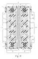
- FIG. 9illustrates an alternate placement of fasteners on a fixation axis orthogonal to a deflection axis.
- FIG. 10illustrates a flexing of an embodiment according to FIG. 9 .
- FIG. 11illustrates an embodiment of the flexible electro-optic display assembly where the layers of the laminate assembly are held together by a single fastener in conjunction with a collar positioned along a second orthogonal axis.
- FIG. 12illustrates a detail view of the collar of FIG. 11 .
- FIGS. 13A, B and Cillustrate an alternative embodiment of FIGS. 8 and 9, wherein the fasteners take the form of clips.
- FIGS. 14A and Billustrate details of the clips used in FIG. 13 .
- FIG. 15illustrates an embodiment in which a single rivet assembly is employed to hold together the layers of the laminate assembly.
- FIGS. 16A, B and Cillustrate detail views of the rivet assembly.
- the enhanced flexibility of the electro-optic display assemblies according to the inventionis achieved by employing laminate display structures in which there is little, if any, bonding between adjacent layers of the laminate assembly. If any bonding is used, it is localized to areas where stress induced by flexing of the laminate assembly is minimized. Therefore, the invention provides an electro-optic display assembly having laminate layers with enhanced flexibility over known display assemblies.
- the inventioncan be applied to any electro-optic display having two or more layers including, but not limited to, displays employing electro-optic materials such as liquid crystals, polymer dispersed liquid crystals, electrophoretic microparticles, rotating bichromal microbeads, thin film electroluminescent material, thin film photoluminescent material, organic light emitting diodes and other electrochomic materials, and the like.
- electro-optic materialssuch as liquid crystals, polymer dispersed liquid crystals, electrophoretic microparticles, rotating bichromal microbeads, thin film electroluminescent material, thin film photoluminescent material, organic light emitting diodes and other electrochomic materials, and the like.
- An electro-optic display elementcan be defined as an element that comprises a material having an optical state that changes as a function of an applied electric or magnetic field, including photoelectric-induced luminescence. That is, the material is “switchable” from one optical state to another. Generally, the switchable material is associated with one or more substrates on which electrodes may be located to change the optical state of the material in accordance with a desired pattern.
- electro-optic displaysemploying the switchable electro-optic material disposed between two substrates that are bonded together to form a so-called microencapsulated display.
- electrophoretic displaysachieve images by electrophoresis, the rapid migration of microparticles in colloidal suspensions.
- light scattering particlesare moved within a dyed colloidal suspension by electrostatic forces. The particles either move toward the viewer, in which case the typically white particles are observed, or to the surface away from the viewer, in which case the white particles are hidden by the dark dye.
- Cholesteric displaysemploy a cholesteric liquid crystal material that, when sandwiched between conducting electrodes, can be switched between two stable states—the so-called focal conic and planar states—in which the helical structures of the liquid crystal have different orientations.
- focal conic statethe helical structures are unaligned and the liquid crystal is transparent.
- planar statethe axes of the helical structures are all perpendicular to the display's surface resulting in essentially monochromatic transmission by the display.
- microencapsulated displayemploys microscopic beads, randomly dispersed and held in place between two plastic substrates by a flexible elastomeric matrix of oil-filled cavities.
- the ballshave strongly contrasting hemispheres, black on one side and white on the other.
- the white sideis highly reflective, while the black side absorbs light.
- Each hemispherehas a unique intrinsic charge, resulting in a force on the ball when an electric field is applied and the axis of the ball is not aligned with the field.
- the side of the ball presented for displaydepends on the polarity of the voltage applied to the electrode.
- LCDsLiquid crystal displays
- PDLCDspolymer dispersed displays
- the orientation of the moleculesis random and light is scattered by the droplets.
- Applying a voltage to the electrodes of the PDLCDcauses the LC molecules to become aligned, resulting in the display becoming transparent.
- electro-optic displaysemploying an electro-optic (or photo-optic) material disposed on one substrate.
- thin film electroluminescent (TFEL) displaysemploy a glass sheet as a substrate that is coated with an electrode (e.g., indium tin oxide) and a light-emitting phosphor film (e.g., ZnS:Mn).
- an electrodee.g., indium tin oxide
- a light-emitting phosphor filme.g., ZnS:Mn
- a thin film black layeris then deposited to provide optical contrast, followed by application of a rear electrode (e.g., aluminum).
- the displayis then “encapsulated” with a solid gel and a glass cover plate to keep out moisture.
- These displaysalso can employ additional layers on an outer surface of the electro-optic layer and/or the substrate layer, such as but not limited to, absorption and interference filters, reflective layers, protective layers, and the like.
- OLEDsOrganic light emitting diodes
- the OLEDcan employ a glass substrate as a substrate that is coated with an electrode and a light-emitting small molecule based on, e.g., aluminum quinolate (Alq3).
- Alq3aluminum quinolate
- These displaysalso can employ additional layers on an outer surface of the electro-optic layer and/or the substrate layer, such as but not limited to, polarizer layers, reflective layers, protective layers, and the like.
- Each of the foregoing embodiments of electro-optic displayscan additionally include a touchscreen element incorporated into the overall display assembly, for applications requiring input by a user.
- the inventionprovides a flexible electro-optic display assembly comprising an electro-optic display element that comprises a material having an optical state that changes as a function of an applied electric or magnetic field, at least one laminar layer in sliding apposition to the display element, and optionally one or more additional slidingly apposed laminar layers, wherein the electro-optic display element, the at least one laminar layer and the optional one or more additional laminar layers comprise individual layers of a laminate assembly; and a structure element for fastening together the individual layers of the laminate assembly, wherein the structure element engages a portion of the laminate assembly so as to maintain the individual layers of the laminate assembly in the sliding apposition, wherein upon flexing of the laminate assembly, the individual layers slide relative to each other.
- a flexible electro-optic display assembly 1includes an electro-optic display element that contains an electro-optic material 2 , disposed between two substrates 3 that are bonded together, such as by a gasket 4 . Bonding between two or more substrates can be achieved by an adhesive, by ultrasonic welding, by laser cutting, or the like. The adhesive can be an ultraviolet cured adhesive, if desired. The type of bonding of the substrates is not critical to the invention. Although two substrates are illustrated, an electro-optic display element having one substrate is not excluded. Further, the display element is not limited to any one type of element design.
- electro-optic materialemployed and the configuration of the material with or without other compounds or electrode materials within the element are not critical to the invention.
- spacers 5are shown as an example of other non-limited materials that can be included in the electro-optic display element.
- the substrate(s) 3can be made of commonly used optically clear materials such as, but not limited to, cast allyl-diglycol carbonate, or the like, which is a relatively rigid material.
- Flexible clear plastic materialsincluding, but not limited to, polycarbonate, polyethersulfone, polyethylene naphthalate, and the like, that are well known to those skilled in the art, can also be employed as the substrate(s).
- the substrate(s)may be made of clear glass, preferably a very thin flexible glass.
- a suitable flexible glass substrateis about 0.030 mm thick and available from Schott Glass Technologies, Inc., Duryea, Pa.
- the substratecan comprise a composite of a polymer and a ceramic or a composite of a polymer and an inorganic material, which are well known materials. Moreover, if two or more substrates are employed, they can be individually made from different materials.
- An advantage of the display assembly according to the inventionis that commonly obtained plastic, glass or composite substrate materials can be employed that are optimized for such desirable features as hardness, scratch-resistance, puncture resistance, and the like, but can have very little elasticity or be very flexible.
- the display assembly 1also includes one or more layers adjacent to an outer surface of the electro-optic material and/or to at least one of the substrates 3 , to achieve the desired electro-optic effect.
- These layerscan include, but are not limited to, polarizers 6 , a reflector 7 , and the like, but can include other or alternative desirable layers, such as an analyzer, an optical compensation element, or other layers known to those of ordinary skill in the art of electro-optic displays. Commonly used polarizers, analyzers and reflectors can be employed without limitation.
- these layerscan add desired features, such as hardness and scratch resistance or anti-reflection layers to the display assembly.
- layerscan include an anti-scratch layer or any type of protective barrier layer.
- the layersmay include a flexible touchscreen input subassembly, currently manufactured and incorporated into rigid products such as Palm Pilots or other PDAs.
- the layers, together with the electro-optic display elementare all slidingly apposed and comprise individual layers of a laminate assembly 8 .
- the individual layers of the laminate assemblyare held together in sliding apposition by a structure element, such as a flexible frame structure 9 having an inner periphery 10 defining a viewing area 11 which is better seen in FIG. 2 .
- the flexible frame structureengages peripheral portions of the laminate assembly so as to maintain the layers of the laminate assembly 8 in the sliding apposition until flexing of the display assembly allows the individual layers to slide relative to each other.
- the materials used for the flexible frame structureare preferably softer and more elastic than those used for the substrates, and have no requirement to be optically clear.
- the flexible framecan be made from vinyl, urethane, polyethylenes, polyvinyl chloride, cellulose derivatives, vinyl resins, polystyrenes, polyamides, polyimides, polycarbonates, paper, rubber; mica tape, plate or sheet, glass cloth, and the like.
- the flexible framecan be made from a polymer film, preferably an adhesive-back film.
- Exemplary filmscan include, but are not limited to, Kapton®, Nomex® and Mylars® (E.I. duPont de Nemours Co.).
- an adhesive-based filmcan be folded over the laminate stack.
- An optically clear filmcan cover all or part of the viewing area for the electro-optic display, if desired.
- spacing elements 12that prevent direct contact between the inner surfaces of the laminate layers may be incorporated, as illustrated in FIG. 1 B.
- the spacing elementsare used to prevent optical interference patterns resulting when the inner surfaces come in contact. Such patterns are commonly called Newton rings or fringes. Spacing between layers is usually maintained at less than 10 mils, though the exact gap is not critical other than that the gap must be greater than 1 ⁇ 2 the longest wavelength of light of interest.
- Methods commonly used by those skilled in the artinclude printing the spacer elements onto at least one of the surfaces. Other methods may involve use of adhesive-coated microspheres such as those used to maintain the cell gap in a liquid crystal cell.
- FIG. 1Cillustrates an embodiment of the electro-optic display assembly that includes a second electro-optic display element 13 , including its attendant layers that are similar to those of the display element 12 and are designated with an “A” in addition to the numerical identification.
- a flexible electro-optic display assemblycomprises a first electro-optic display element and a second electro-optic display element, wherein the first and second electro-optic display elements independently comprise a material having an optical state that changes as a function of an applied electric or magnetic field, at least one laminar layer in sliding apposition to the first or the second display element, and optionally one or more additional slidingly apposed laminar layers, wherein the first and second electro-optic display elements, the at least one laminar layer and the optional one or more additional laminar layers comprise individual layers of a laminate assembly; and a structure element 9 for fastening together the individual layers of the laminate assembly, wherein the structure element engages a portion of the laminate assembly so as to maintain the individual layers of the laminate assembly
- the first and second display elementsmay be the same or may be different from each other.
- An advantage of this embodimentis that the electro-optic display assembly can comprise a front portion 11 and a back portion 11 A, and the first and the second electro-optic display elements are positioned in the laminate assembly such that the first electro-optic display element provides an image on the front portion of the electro-optic display assembly and the second electro-optic display element provides an image on the back portion of the electro-optic display assembly.
- FIG. 2illustrates one embodiment of a structure element such as the flexible frame in which the shape of the frame is generally a rectangle having four sides 12 .
- a flexible framecan have a variety of different shapes, such as oval or irregular shapes, and the like, without limitation.
- a flexible tail 13 for connecting the liquid display element to conventional display driver electronicsis also illustrated.
- the flexible framecan have an outer periphery 14 for inserting the flexible display assembly into a housing (not shown) such as a mobile communications device, a watch, a PDA, or the like, or other electronic device, such as a cellular telephone, a calculator, a clock, an integrated circuit chip card, a pager, a computer, a television set, or the like.
- mounting holes 15can be placed between the outer and inner peripheries of the flexible frame structure.
- exemplary mounting meanscan be, but are not limited to, pegs, rivets, velcro, or the like, or combinations of these.
- the mounting meanscan be flexible or rigid.
- the mounting meanscan employ adhesives for mounting the display assembly into the device.
- the structure elementcan engage the peripheral portions of the laminate assembly by overmolding, such as with a urethane or other thermoplastic polymer.
- the device in which the laminate assembly is to be employedcan itself serve as the structure element.
- FIGS. 4 and 5illustrate a watch band 20 that is a structure element for maintaining the individual layers of the laminate assembly of the electro-optic display 21 in the sliding apposition.
- the device, such as the watch bandcan further comprise conventional electronics, battery and controls 22 , as known to those skilled in the art of electro-optic displays. As shown more clearly in FIG.
- the flexible electro-optic display assemblyincludes the electro-optic display element 23 comprising the electro-optic material dispersed between substrates 24 and 25 and a reflector layer 26 slidingly apposed to an outer surface of one of the substrates 24 .
- a clear protective top layer 27can optionally be added to protect the display assembly from damage.
- small holes or notches 28can be introduced in the peripheral areas of the laminate stack that can become filled with the polymer during the molding process.
- Such notches or holescan be produced, for example, by die cutting or by laser, such as a carbon dioxide laser, by known methods.
- the flexible electro-optic display assemblycomprises a flexible frame structure having a top portion comprising an area for viewing the electro-optic display, and a body portion, wherein the top portion and the body portion comprise a housing for the laminate assembly so as to maintain the individual layers of the laminate assembly in the sliding apposition, wherein upon flexing of the housing, the individual layers of the laminate assembly slide relative to each other.
- FIGS. 6A and 6BAn illustrative example of this embodiment is shown in FIGS. 6A and 6B, in which the laminate assembly 30 is incorporated into a laminated flexible plastic card 31 , such as an integrated circuit chip card.
- the cardcomprises a top cover 32 for viewing the electro-optic display 33 and a body portion 34 that is preferably opaque.
- the laminate assembly 30is layered and fitted into an appropriately sized opening 35 in the body portion 34 and the top cover 32 is laminated to the body portion 34 , thus forming a housing that encloses and holds together the layers of the laminate assembly in sliding apposition.
- the body portion 34comprises an inner body 36 and a bottom cover 37 .
- the top cover 32 , the inner body 36 and the bottom cover 37are configured to provide an appropriately sized opening 38 for the laminate assembly 30 to hold together the layers of the laminate assembly in sliding apposition and to contain the assembly within the housing.
- the individual layers of the laminate assemblyslide relative to each other.
- the integrated circuit chip cardcan further comprise electronic connections to the laminate assembly, integrated circuits, battery and controls 39 , including micromodular electronic systems and the like, as known to those skilled in the art of electronic displays in integrated circuit chip cards, such as the chip card disclosed in U.S. Pat. No. 6,019,284, the disclosure of which is hereby incorporated by reference.
- FIGS. 7A and 7Billustrate more detailed views of embodiments of the inside of the top cover of a smart card 131 and the non-viewing area surface of the laminate assembly.
- the electro-optic display assembly 130is connected to a micromodule (a printed circuit board) 132 having an integrated circuit 133 for smart card functions. Also illustrated are additional integrated circuits and passive components 134 located on the display assembly 130 .
- a battery 135is connected to the display assembly by a contact ledge 136 .
- the display assemblyis connected to the micromodule by a contact ledge 137 .
- FIG. 7Billustrates another embodiment of the inside of the top cover that does not include a separate micromodule. That is, the display assembly 130 comprises a micromodule area 138 containing integrated circuit 133 for smart card functions.
- the battery 135is connected to the micromodule area 138 of the display assembly 130 by the contact ledge 136 .
- the structure elementsuch as the flexible frame structure and/or fasteners described herein
- the structure elementwhen the display is not in flexed configuration, the structure element holds the layers of the laminate assembly in the correct alignment to allow the display to function correctly.
- the performance of the displaymay be degraded. For those embodiments which have degraded performance during flexure, once the display is allowed to resume its original shape the display will regain its original performance characteristics.
- the laminate assembly and structure elementare manufactured in a pre-flexed configuration and the structure element holds the layers of the flexed laminate assembly in the correct alignment to allow the display to function correctly.
- the electro-optic display element, the at least one laminar layer and the optional one or more additional laminar layerscomprise individual layers of a laminate assembly having a deflection axis.
- a fasteneris provided for fastening together the individual layers of the laminate assembly. The fastener maintains the individual layers of the laminate assembly in a first position relative to one another at the fastener, and wherein upon flexing of the display assembly, the individual layers slide relative to each other in regions outside of the fastener.
- FIGS. 8 and 9illustrate a laminate assembly 40 that is held together by two or more rigid or flexible fasteners such as, but not limited to, two or more rivets 41 placed on a so-called fixation axis 43 that is at a non-zero angle to a deflection axis 42 . That is, the layers of the laminate assembly 40 cannot slide relative to each other on the fixation axis. However, the layers can slide relative to each other outside of the fixation axis.
- the deflection axis 42is determined by the axis at which the assembly is bent; that is, it is non-specific to a particular display and will change depending on the direction in which the display is bent.
- the fixation axis 43 along which the rivets 41 are placedcan be at a side 44 of the laminate assembly or can be centrally located, as illustrated in FIG. 8 and 9, respectively.
- the fixation axiscan be located anywhere on the laminate assembly depending on the configuration and location of the deflection axis.
- two or more fasteners 50can hold together the layers of the laminate assembly 51 and are placed on an axis 52 orthogonal to a deflection axis 53 .
- the orthogonal axisis a fixation axis.
- the layerscan slide relative to each other outside of the fixation axis during flexing of the laminate assembly.
- a single fastenersuch as a rivet 61 is used in conjunction with a collar 62 positioned along a fixation axis 63 .
- the collar positioned along the fixation axismaintains rotational alignment between the layers of the laminate assembly 60 about the axis 64 of the fastener 61 , but still allows for flexure along the displacement axis 65 .
- the collar 62may be a rigid, semi-flexible, or flexible element that may be either fully circumferential around the laminate assembly 60 or only semi-circumferential.
- a semi-circumferential collarcomprises an elongated portion 66 having opposite ends 67 and 68 .
- a fully circumferential collarcomprises an additional elongated portion 69 connecting the ends 67 and 68 .
- the collarmay also contain features which constrain the motion of one or more layers relative to each other along the displacement axis. For example, as illustrated in FIG. 12, molded protrusions 70 on an inner wall 71 of the collar keep the collar from sliding off the laminate assembly.
- one or more clips 81can be employed as fasteners to hold together the laminate stack forming the display 80 .
- the clipscan be located on the sides of the display.
- the clips 81can be located in the comers of the display if the display is rectangular in shape. That is, the display assembly has a periphery comprising at least a first side 82 and a second side 83 that intersect to form a comer area 88 of the assembly, and the fastener is located in the comer area of the display assembly. If the display has curved outer edges, the clips can be formed so as to closely conform to the perimeter of the display edge with which it comes into contact.
- FIGS. 14A and 14BPossible configurations of a clip 90 conforming to a side of the display and a clip 91 conforming to a comer of the display are illustrated in FIGS. 14A and 14B respectively. It is also preferable that the upper 93 or lower 94 inner surfaces, respectively, of the clips which come into contact with the laminate stack have protrusions 92 that extend into holes or depressions in the outer layers of the laminate stack so as to retain the clips in the desired position relative to the laminate stack.
- FIG. 13Billustrates a hole or depression pattern 84 in a top sheet 85 of the laminate stack.
- FIG. 13Cillustrates a hole or depression pattern 86 in a bottom sheet 87 of the laminate stack.
- the protrusionsmay be on both the upper and lower inner surfaces of the clips, but it is preferable that the protrusions only be on one of the inner surfaces.
- the latching mechanism provided by the protrusion/hole combinationmay be augmented with a heat or ultraviolet light activated adhesive on the inner surface with the protrusion. This single-sided latching mechanism allows for all laminate layers to slide apposing with each other. Additionally, the side of the display on which the single-sided latch is located can be alternated so that each outer laminate layer can have at least one clip latched to it.
- a single rivet assembly 96may be used as shown in FIG. 15 and in more detail in FIG. 16 wherein the rivet is located in a corner of the display 95 .
- Featuresare incorporated in the rivet assembly 96 that, when riveted to the laminate stack, align with edges of the stack that intersect at the corner at which the rivet is located.
- FIGS. 16A, 16 B and 16 Cillustrates an outer oblique view of the top half of the rivet assembly 96 , a rear view of the top of the rivet assembly, and a view of the bottom half of the rivet assembly, respectively, showing corner alignment rails 97 and insertion hole 98 for a rivet 99 .
- a single rivet with corner alignment featurescan be used to hold together the laminate stack, both rotationally and laterally, while still allowing for the individual layers to slide against each at all points other than at the rivet.
- any of these embodiments incorporating one or more fastenerspreferably optically clear fasteners may be used in the area for viewing the electro-optic display, if desired.
- Means for fastening the layers togethercan also include other conventional fasteners, such as pins, bolts, screws, clamp pairs, and the like, known to those skilled in the art.
- the fastenersmay be rigid or flexible.
Landscapes
- Physics & Mathematics (AREA)
- Nonlinear Science (AREA)
- Engineering & Computer Science (AREA)
- Chemical & Material Sciences (AREA)
- Optics & Photonics (AREA)
- General Physics & Mathematics (AREA)
- Crystallography & Structural Chemistry (AREA)
- Mathematical Physics (AREA)
- Ceramic Engineering (AREA)
- Mechanical Engineering (AREA)
- Devices For Indicating Variable Information By Combining Individual Elements (AREA)
- Liquid Crystal (AREA)
- Electroluminescent Light Sources (AREA)
Abstract
Description
Claims (41)
Priority Applications (5)
| Application Number | Priority Date | Filing Date | Title |
|---|---|---|---|
| US10/147,628US6655788B1 (en) | 2002-05-17 | 2002-05-17 | Composite structure for enhanced flexibility of electro-optic displays with sliding layers |
| PCT/US2003/014644WO2004003645A1 (en) | 2002-05-17 | 2003-05-09 | Composite structure for enhanced flexibility of eletro-optic displays |
| AU2003241410AAU2003241410A1 (en) | 2002-05-17 | 2003-05-09 | Composite structure for enhanced flexibility of eletro-optic displays |
| CNB038143755ACN100371786C (en) | 2002-05-17 | 2003-05-09 | Composite structure for increasing flexibility of electro-optic display |
| JP2004517545AJP4617157B2 (en) | 2002-05-17 | 2003-05-09 | Composite structure to increase flexibility of electro-optic display |
Applications Claiming Priority (1)
| Application Number | Priority Date | Filing Date | Title |
|---|---|---|---|
| US10/147,628US6655788B1 (en) | 2002-05-17 | 2002-05-17 | Composite structure for enhanced flexibility of electro-optic displays with sliding layers |
Publications (2)
| Publication Number | Publication Date |
|---|---|
| US20030214612A1 US20030214612A1 (en) | 2003-11-20 |
| US6655788B1true US6655788B1 (en) | 2003-12-02 |
Family
ID=29419058
Family Applications (1)
| Application Number | Title | Priority Date | Filing Date |
|---|---|---|---|
| US10/147,628Expired - LifetimeUS6655788B1 (en) | 2002-05-17 | 2002-05-17 | Composite structure for enhanced flexibility of electro-optic displays with sliding layers |
Country Status (5)
| Country | Link |
|---|---|
| US (1) | US6655788B1 (en) |
| JP (1) | JP4617157B2 (en) |
| CN (1) | CN100371786C (en) |
| AU (1) | AU2003241410A1 (en) |
| WO (1) | WO2004003645A1 (en) |
Cited By (58)
| Publication number | Priority date | Publication date | Assignee | Title |
|---|---|---|---|---|
| US6801001B2 (en)* | 2000-10-27 | 2004-10-05 | Science Applications International Corporation | Method and apparatus for addressing micro-components in a plasma display panel |
| US20050224935A1 (en)* | 2004-04-02 | 2005-10-13 | Marc Schaepkens | Organic electronic packages having hermetically sealed edges and methods of manufacturing such packages |
| WO2005072304A3 (en)* | 2004-01-28 | 2006-12-28 | Kent Displays Inc | Liquid crystal display |
| US7170481B2 (en)* | 2003-07-02 | 2007-01-30 | Kent Displays Incorporated | Single substrate liquid crystal display |
| US20070103429A1 (en)* | 2005-11-10 | 2007-05-10 | Seiko Epson Corporation | Electrophoretic display module and electrophoretic display device |
| US20070152956A1 (en)* | 2002-06-10 | 2007-07-05 | E Ink Corporation | Electro-optic display with edge seal |
| US20070152928A1 (en)* | 2004-01-28 | 2007-07-05 | Kents Displays Incorporated | Drapable liquid crystal transfer display films |
| US20070277659A1 (en)* | 2006-06-02 | 2007-12-06 | Kent Diplays Incorporated | Method of simultaneous singulation and edge sealing of plastic displays |
| US20080309598A1 (en)* | 2004-01-28 | 2008-12-18 | Doane J William | Stacked color photodisplay |
| CN101681075A (en)* | 2007-04-16 | 2010-03-24 | 聚合物视象有限公司 | A device comprising a multilayer structure and rollers |
| US20100101856A1 (en)* | 2008-10-24 | 2010-04-29 | Samsung Mobile Display Co., Ltd. | Organic light emitting diode display |
| US7737928B2 (en) | 2003-07-02 | 2010-06-15 | Kent Displays Incorporated | Stacked display with shared electrode addressing |
| US7791700B2 (en) | 2005-09-16 | 2010-09-07 | Kent Displays Incorporated | Liquid crystal display on a printed circuit board |
| US20110001613A1 (en)* | 2009-07-03 | 2011-01-06 | Craig Michael Ciesla | Method for adjusting the user interface of a device |
| US20110007382A1 (en)* | 2009-07-09 | 2011-01-13 | Jiangsu Lexvu Electronics Co., Ltd. | Colored electrophoretic display |
| US8154527B2 (en) | 2008-01-04 | 2012-04-10 | Tactus Technology | User interface system |
| US8179377B2 (en) | 2009-01-05 | 2012-05-15 | Tactus Technology | User interface system |
| US8179375B2 (en) | 2008-01-04 | 2012-05-15 | Tactus Technology | User interface system and method |
| US8199124B2 (en) | 2009-01-05 | 2012-06-12 | Tactus Technology | User interface system |
| US8207950B2 (en) | 2009-07-03 | 2012-06-26 | Tactus Technologies | User interface enhancement system |
| US8339040B2 (en) | 2007-12-18 | 2012-12-25 | Lumimove, Inc. | Flexible electroluminescent devices and systems |
| US8456438B2 (en) | 2008-01-04 | 2013-06-04 | Tactus Technology, Inc. | User interface system |
| US8547339B2 (en) | 2008-01-04 | 2013-10-01 | Tactus Technology, Inc. | System and methods for raised touch screens |
| US8553005B2 (en) | 2008-01-04 | 2013-10-08 | Tactus Technology, Inc. | User interface system |
| US8570295B2 (en) | 2008-01-04 | 2013-10-29 | Tactus Technology, Inc. | User interface system |
| US8587541B2 (en) | 2010-04-19 | 2013-11-19 | Tactus Technology, Inc. | Method for actuating a tactile interface layer |
| US8619035B2 (en) | 2010-02-10 | 2013-12-31 | Tactus Technology, Inc. | Method for assisting user input to a device |
| US20140054569A1 (en)* | 2012-08-22 | 2014-02-27 | Moon-Seok ROH | Organic light emitting diode display and method of manufacturing the same |
| US8665236B2 (en) | 2011-09-26 | 2014-03-04 | Apple Inc. | Electronic device with wrap around display |
| US8704790B2 (en) | 2010-10-20 | 2014-04-22 | Tactus Technology, Inc. | User interface system |
| US20140285747A1 (en)* | 2013-03-20 | 2014-09-25 | Lg Display Co., Ltd. | Liquid crystal display with narrow bezel area |
| US8922503B2 (en) | 2008-01-04 | 2014-12-30 | Tactus Technology, Inc. | User interface system |
| US8922502B2 (en) | 2008-01-04 | 2014-12-30 | Tactus Technology, Inc. | User interface system |
| US8922510B2 (en) | 2008-01-04 | 2014-12-30 | Tactus Technology, Inc. | User interface system |
| US8928621B2 (en) | 2008-01-04 | 2015-01-06 | Tactus Technology, Inc. | User interface system and method |
| US8947383B2 (en) | 2008-01-04 | 2015-02-03 | Tactus Technology, Inc. | User interface system and method |
| US9013417B2 (en) | 2008-01-04 | 2015-04-21 | Tactus Technology, Inc. | User interface system |
| US9052790B2 (en) | 2008-01-04 | 2015-06-09 | Tactus Technology, Inc. | User interface and methods |
| US9063627B2 (en) | 2008-01-04 | 2015-06-23 | Tactus Technology, Inc. | User interface and methods |
| US9128525B2 (en) | 2008-01-04 | 2015-09-08 | Tactus Technology, Inc. | Dynamic tactile interface |
| US9239623B2 (en) | 2010-01-05 | 2016-01-19 | Tactus Technology, Inc. | Dynamic tactile interface |
| US9274612B2 (en) | 2008-01-04 | 2016-03-01 | Tactus Technology, Inc. | User interface system |
| US9280224B2 (en) | 2012-09-24 | 2016-03-08 | Tactus Technology, Inc. | Dynamic tactile interface and methods |
| US9298261B2 (en) | 2008-01-04 | 2016-03-29 | Tactus Technology, Inc. | Method for actuating a tactile interface layer |
| US9367132B2 (en) | 2008-01-04 | 2016-06-14 | Tactus Technology, Inc. | User interface system |
| US9372565B2 (en) | 2008-01-04 | 2016-06-21 | Tactus Technology, Inc. | Dynamic tactile interface |
| US20160202536A1 (en)* | 2015-01-13 | 2016-07-14 | Samsung Display Co., Ltd. | Liquid crystal display |
| US9405417B2 (en) | 2012-09-24 | 2016-08-02 | Tactus Technology, Inc. | Dynamic tactile interface and methods |
| US9423875B2 (en) | 2008-01-04 | 2016-08-23 | Tactus Technology, Inc. | Dynamic tactile interface with exhibiting optical dispersion characteristics |
| US9552065B2 (en) | 2008-01-04 | 2017-01-24 | Tactus Technology, Inc. | Dynamic tactile interface |
| US9557813B2 (en) | 2013-06-28 | 2017-01-31 | Tactus Technology, Inc. | Method for reducing perceived optical distortion |
| US9557915B2 (en) | 2008-01-04 | 2017-01-31 | Tactus Technology, Inc. | Dynamic tactile interface |
| US9588683B2 (en) | 2008-01-04 | 2017-03-07 | Tactus Technology, Inc. | Dynamic tactile interface |
| US9588684B2 (en) | 2009-01-05 | 2017-03-07 | Tactus Technology, Inc. | Tactile interface for a computing device |
| US9612659B2 (en) | 2008-01-04 | 2017-04-04 | Tactus Technology, Inc. | User interface system |
| US9684339B2 (en) | 2015-02-03 | 2017-06-20 | Microsoft Technology Licensing, Llc | Bendable display assembly |
| US9720501B2 (en) | 2008-01-04 | 2017-08-01 | Tactus Technology, Inc. | Dynamic tactile interface |
| US9760172B2 (en) | 2008-01-04 | 2017-09-12 | Tactus Technology, Inc. | Dynamic tactile interface |
Families Citing this family (46)
| Publication number | Priority date | Publication date | Assignee | Title |
|---|---|---|---|---|
| US7715088B2 (en) | 2000-03-03 | 2010-05-11 | Sipix Imaging, Inc. | Electrophoretic display |
| US20070237962A1 (en) | 2000-03-03 | 2007-10-11 | Rong-Chang Liang | Semi-finished display panels |
| TW568287U (en)* | 2002-10-24 | 2003-12-21 | Yuan-Sung Weng | Wrist-carrying watch with flexible organic electroluminescent display |
| US20170052422A1 (en)* | 2002-11-26 | 2017-02-23 | E Ink Corporation | Flexible electronic circuits and displays |
| GB2428860B (en)* | 2004-01-28 | 2007-08-01 | Kent Displays Inc | Drapable liquid crystal transfer display films |
| US7230599B2 (en)* | 2004-02-09 | 2007-06-12 | Inventec Corporation | Display device for data processing equipment |
| US20060132025A1 (en)* | 2004-12-22 | 2006-06-22 | Eastman Kodak Company | Flexible display designed for minimal mechanical strain |
| US7722929B2 (en) | 2005-08-18 | 2010-05-25 | Corning Incorporated | Sealing technique for decreasing the time it takes to hermetically seal a device and the resulting hermetically sealed device |
| US7829147B2 (en) | 2005-08-18 | 2010-11-09 | Corning Incorporated | Hermetically sealing a device without a heat treating step and the resulting hermetically sealed device |
| US20080206589A1 (en)* | 2007-02-28 | 2008-08-28 | Bruce Gardiner Aitken | Low tempertature sintering using Sn2+ containing inorganic materials to hermetically seal a device |
| US20070040501A1 (en) | 2005-08-18 | 2007-02-22 | Aitken Bruce G | Method for inhibiting oxygen and moisture degradation of a device and the resulting device |
| US8446549B2 (en) | 2005-11-29 | 2013-05-21 | Creator Technology B.V. | Color filter to prevent color errors in a roll up display |
| JP4528923B2 (en)* | 2005-12-05 | 2010-08-25 | 学校法人金沢工業大学 | EL element |
| US20070246717A1 (en)* | 2006-04-21 | 2007-10-25 | Ng Kee Y | Light source having both thermal and space efficiency |
| US8062120B2 (en)* | 2006-04-21 | 2011-11-22 | Charles Zapata | Dynamic card system and method |
| US20080048178A1 (en)* | 2006-08-24 | 2008-02-28 | Bruce Gardiner Aitken | Tin phosphate barrier film, method, and apparatus |
| US8017220B2 (en) | 2006-10-04 | 2011-09-13 | Corning Incorporated | Electronic device and method of making |
| JP2008250073A (en)* | 2007-03-30 | 2008-10-16 | Dic Corp | Optical drive device for rewritable optical address type liquid crystal display device |
| TWI361331B (en)* | 2007-06-01 | 2012-04-01 | Pervasive Display Co Ltd | E-paper apparatus |
| DE102008028635A1 (en)* | 2008-06-18 | 2009-12-24 | Deutsche Telekom Ag | Mobile terminal i.e. mobile telephone, for telecommunication via e.g. communication network, has touch screen with surface structure that is different from flat surface, where screen exhibits curvature or bend about axis in partial area |
| EP2314055A1 (en) | 2008-06-18 | 2011-04-27 | Deutsche Telekom AG | Mobile telephone with convex arched touch screen |
| KR101305742B1 (en)* | 2008-08-06 | 2013-09-06 | 엘지이노텍 주식회사 | Display device |
| JP2012523661A (en)* | 2009-04-08 | 2012-10-04 | コーニンクレッカ フィリップス エレクトロニクス エヌ ヴィ | Organic light-emitting diode element with aesthetic appearance |
| CN102478727B (en) | 2010-11-28 | 2016-04-06 | 宸鸿科技(厦门)有限公司 | The manufacture method of touch control display apparatus and display device, touch control display apparatus |
| JP2014508213A (en) | 2010-12-10 | 2014-04-03 | ユニバーシティー オブ ウロンゴング | Improvement regarding multi-layer water splitting apparatus and manufacturing method thereof |
| US8525405B2 (en)* | 2011-08-19 | 2013-09-03 | Apple Inc. | Electronic devices with flexible glass polarizers |
| WO2013115277A1 (en)* | 2012-01-30 | 2013-08-08 | 独立行政法人物質・材料研究機構 | Electrochromic gel, method for producing same, method for controlling electronic printing onto electrochromic gel and erasure thereof, and stretchable display |
| GB2500006A (en)* | 2012-03-06 | 2013-09-11 | Teknologian Tutkimuskeskus Vtt Oy | Optical touch screen using cameras in the frame. |
| RU2603772C2 (en) | 2012-06-12 | 2016-11-27 | Монаш Юниверсити | Breathable electrode and method for use in water splitting |
| JP2014150005A (en)* | 2013-02-01 | 2014-08-21 | Toshiba Lighting & Technology Corp | Lighting device |
| KR102052748B1 (en)* | 2013-03-20 | 2019-12-06 | 엘지디스플레이 주식회사 | Liquid Crystal Display Device with Narrow Bezel Area |
| KR20160040615A (en) | 2013-07-31 | 2016-04-14 | 아쿠아하이드렉스 프로프라이어터리 리미티드 | Modular Electrochemical Cells |
| JP5892563B2 (en)* | 2014-08-01 | 2016-03-23 | 日東電工株式会社 | Optical inspection method for display cell of flexible thin film structure and pseudo terminal unit used in the method |
| TWI534518B (en)* | 2015-05-15 | 2016-05-21 | Tintable Kibing Co Ltd | Electrochromic device |
| US10069100B2 (en) | 2015-09-24 | 2018-09-04 | Apple Inc. | Flexible device with decoupled display layers |
| WO2017142078A1 (en)* | 2016-02-18 | 2017-08-24 | 東レ・ダウコーニング株式会社 | Flexible laminate and flexible display using same |
| US10468467B2 (en)* | 2016-03-15 | 2019-11-05 | Sharp Kabushiki Kaisha | Organic electroluminescence display device |
| US9913392B2 (en)* | 2016-04-13 | 2018-03-06 | Motorola Mobility Llc | Flexible display stack-up and method for arranging |
| TWI767948B (en)* | 2016-10-31 | 2022-06-21 | 美商康寧公司 | Layered bendable puncture resistant glass article and method of making |
| TWI627777B (en)* | 2017-07-26 | 2018-06-21 | 財團法人工業技術研究院 | Optical compensation structure |
| CN109559651B (en)* | 2017-09-25 | 2022-03-08 | 广州国显科技有限公司 | Flexible display module and display device |
| KR102516767B1 (en)* | 2017-10-19 | 2023-03-31 | 삼성전기주식회사 | Stiffener and package substrate having the same |
| JP2019132981A (en)* | 2018-01-31 | 2019-08-08 | 株式会社ジャパンディスプレイ | Display |
| CN108375857A (en)* | 2018-02-26 | 2018-08-07 | 江苏天贯碳纳米材料有限公司 | A method of preparing light modulation device using nucleocapsid tack microballon |
| JP2022519575A (en) | 2019-02-01 | 2022-03-24 | アクアハイドレックス, インコーポレイテッド | Electrochemical system with confined electrolyte |
| CN111399314A (en)* | 2020-05-29 | 2020-07-10 | 济南晶众光电科技有限公司 | Nanosecond-speed large-caliber crystal optical shutter device based on optical polarization modulator |
Citations (31)
| Publication number | Priority date | Publication date | Assignee | Title |
|---|---|---|---|---|
| US4685771A (en) | 1985-09-17 | 1987-08-11 | West John L | Liquid crystal display material comprising a liquid crystal dispersion in a thermoplastic resin |
| US4688900A (en) | 1984-03-19 | 1987-08-25 | Kent State University | Light modulating material comprising a liquid crystal dispersion in a plastic matrix |
| US4876441A (en)* | 1984-03-27 | 1989-10-24 | Casio Computer Co., Ltd. | Card-like electronic apparatus |
| US4948232A (en) | 1983-12-16 | 1990-08-14 | Alf Lange | Device for the presentation of information with rollable plastic substrate |
| US5321533A (en) | 1992-09-24 | 1994-06-14 | Kent State Universtiy | Polymer dispersed ferroelectric smectic liquid crystal |
| US5333074A (en) | 1991-12-09 | 1994-07-26 | U.S. Philips Corporation | Display device comprising liquid crystalline material locally formed into a polymer network |
| US5473450A (en) | 1992-04-28 | 1995-12-05 | Sharp Kabushiki Kaisha | Liquid crystal display device with a polymer between liquid crystal regions |
| US5679414A (en) | 1992-11-18 | 1997-10-21 | Fuji Xerox Co., Ltd. | Liquid crystal-polymer composite film, electro-optical element using the same, and process for producing electro-optical element |
| US5751388A (en) | 1995-04-07 | 1998-05-12 | Honeywell Inc. | High efficiency polarized display |
| US5949508A (en) | 1997-12-10 | 1999-09-07 | Kent State University | Phase separated composite organic film and methods for the manufacture thereof |
| US5978063A (en) | 1997-04-15 | 1999-11-02 | Xerox Corporation | Smart spacers for active matrix liquid crystal projection light valves |
| US6019284A (en) | 1998-01-27 | 2000-02-01 | Viztec Inc. | Flexible chip card with display |
| US6051639A (en) | 1996-04-01 | 2000-04-18 | The Secretary Of State For Defence In Her Britannic Majesty's Government Of The United Kingdom Of Great Britain And Northern Ireland | Liquid crystal macrocycles |
| US6128056A (en) | 1997-06-04 | 2000-10-03 | Matsushita Electric Industrial Co., Ltd. | Liquid crystal display element in which the polymer liquid crystal composite layer is divided into an active area and a non-active area and method of manufacturing the same |
| US6141071A (en) | 1995-10-30 | 2000-10-31 | Colorlink, Inc. | Switchable achromatic polarization rotator |
| US6195196B1 (en) | 1998-03-13 | 2001-02-27 | Fuji Photo Film Co., Ltd. | Array-type exposing device and flat type display incorporating light modulator and driving method thereof |
| US6211994B1 (en) | 1986-03-31 | 2001-04-03 | Gentex Corporation | Variable transmittance electrochromic devices |
| US20010002858A1 (en) | 1999-12-02 | 2001-06-07 | Tetsuya Kageyama | Flexible LCD panel fabrication method and flexible LCD panel fabrication system used for the same |
| US6284418B1 (en) | 1998-11-16 | 2001-09-04 | Cambridge Scientific, Inc. | Biopolymer-based optical element |
| US6293470B1 (en) | 1997-04-29 | 2001-09-25 | Swedish Advanced Technology Systems Ab | Smartcard and method for its manufacture |
| US6310612B1 (en) | 1997-12-24 | 2001-10-30 | Bridgestone Corporation | Display unit integral with touch panel bonded through an adhesive composition or an adhesive film and production method thereof |
| US6311076B1 (en) | 1997-02-21 | 2001-10-30 | Nokia Mobile Phones Limited | Mobile communication devices |
| US6312304B1 (en) | 1998-12-15 | 2001-11-06 | E Ink Corporation | Assembly of microencapsulated electronic displays |
| US6316278B1 (en) | 1999-03-16 | 2001-11-13 | Alien Technology Corporation | Methods for fabricating a multiple modular assembly |
| US6330208B1 (en) | 1998-10-16 | 2001-12-11 | Xonix Watch Co., Ltd. | Watch with front mounted liquid crystal display and liquid crystal display with reflective sheet |
| US6335818B1 (en) | 1999-10-26 | 2002-01-01 | Xerox Corporation | Bichromal beads having electrolytes therein |
| US20020019296A1 (en) | 1998-06-24 | 2002-02-14 | Viztec, Inc., A Delaware Corporation | Wearable device |
| US6356376B1 (en) | 1997-04-02 | 2002-03-12 | Gentex Corporation | Electrochromic rearview mirror incorporating a third surface metal reflector and a display/signal light |
| US6362915B1 (en) | 1999-10-26 | 2002-03-26 | Xerox Corporation | Bichromal beads having crystalline materials therein |
| US20020180709A1 (en)* | 2001-05-31 | 2002-12-05 | Lichtfuss Hans A. | Flexible electronic viewing device |
| US20020180344A1 (en)* | 2001-05-31 | 2002-12-05 | Lichtfuss Hans A. | Flexible electronic device |
Family Cites Families (7)
| Publication number | Priority date | Publication date | Assignee | Title |
|---|---|---|---|---|
| JPH10333607A (en)* | 1997-05-30 | 1998-12-18 | Idec Izumi Corp | Liquid crystal display device |
| JPH1114971A (en)* | 1997-06-26 | 1999-01-22 | Kyocera Corp | Film LCD mounting structure |
| JP2002501263A (en)* | 1998-01-27 | 2002-01-15 | ビズテック インコーポレイテッド | Transmission of advertisements to smart cards |
| US5931764A (en)* | 1998-06-24 | 1999-08-03 | Viztec, Inc. | Wearable device with flexible display |
| KR100835757B1 (en)* | 1998-10-28 | 2008-06-05 | 비아, 인크 | Flex-to-fixed user interface devices |
| JP3697104B2 (en)* | 1999-03-30 | 2005-09-21 | セイコーエプソン株式会社 | Liquid crystal device and projection display device having the same |
| JP3980405B2 (en)* | 2002-05-17 | 2007-09-26 | 株式会社東芝 | Image display device |
- 2002
- 2002-05-17USUS10/147,628patent/US6655788B1/ennot_activeExpired - Lifetime
- 2003
- 2003-05-09JPJP2004517545Apatent/JP4617157B2/ennot_activeExpired - Lifetime
- 2003-05-09WOPCT/US2003/014644patent/WO2004003645A1/enactiveApplication Filing
- 2003-05-09CNCNB038143755Apatent/CN100371786C/ennot_activeExpired - Lifetime
- 2003-05-09AUAU2003241410Apatent/AU2003241410A1/ennot_activeAbandoned
Patent Citations (34)
| Publication number | Priority date | Publication date | Assignee | Title |
|---|---|---|---|---|
| US4948232A (en) | 1983-12-16 | 1990-08-14 | Alf Lange | Device for the presentation of information with rollable plastic substrate |
| US4688900A (en) | 1984-03-19 | 1987-08-25 | Kent State University | Light modulating material comprising a liquid crystal dispersion in a plastic matrix |
| US4876441A (en)* | 1984-03-27 | 1989-10-24 | Casio Computer Co., Ltd. | Card-like electronic apparatus |
| US4685771A (en) | 1985-09-17 | 1987-08-11 | West John L | Liquid crystal display material comprising a liquid crystal dispersion in a thermoplastic resin |
| US6211994B1 (en) | 1986-03-31 | 2001-04-03 | Gentex Corporation | Variable transmittance electrochromic devices |
| US5333074A (en) | 1991-12-09 | 1994-07-26 | U.S. Philips Corporation | Display device comprising liquid crystalline material locally formed into a polymer network |
| US5473450A (en) | 1992-04-28 | 1995-12-05 | Sharp Kabushiki Kaisha | Liquid crystal display device with a polymer between liquid crystal regions |
| US5530566A (en) | 1992-09-24 | 1996-06-25 | Kent State University | Polymer dispersed ferroelectric smectic liquid crystal formed by inducing a force during phase separation |
| US5321533A (en) | 1992-09-24 | 1994-06-14 | Kent State Universtiy | Polymer dispersed ferroelectric smectic liquid crystal |
| US5679414A (en) | 1992-11-18 | 1997-10-21 | Fuji Xerox Co., Ltd. | Liquid crystal-polymer composite film, electro-optical element using the same, and process for producing electro-optical element |
| US5751388A (en) | 1995-04-07 | 1998-05-12 | Honeywell Inc. | High efficiency polarized display |
| US6310671B1 (en) | 1995-04-07 | 2001-10-30 | Honeywell, Inc. | Polarization sensitive scattering element |
| US5999239A (en) | 1995-04-07 | 1999-12-07 | Honeywell Inc. | Method for making a polarization-sensitive optical element |
| US6141071A (en) | 1995-10-30 | 2000-10-31 | Colorlink, Inc. | Switchable achromatic polarization rotator |
| US6051639A (en) | 1996-04-01 | 2000-04-18 | The Secretary Of State For Defence In Her Britannic Majesty's Government Of The United Kingdom Of Great Britain And Northern Ireland | Liquid crystal macrocycles |
| US6311076B1 (en) | 1997-02-21 | 2001-10-30 | Nokia Mobile Phones Limited | Mobile communication devices |
| US6356376B1 (en) | 1997-04-02 | 2002-03-12 | Gentex Corporation | Electrochromic rearview mirror incorporating a third surface metal reflector and a display/signal light |
| US5978063A (en) | 1997-04-15 | 1999-11-02 | Xerox Corporation | Smart spacers for active matrix liquid crystal projection light valves |
| US6293470B1 (en) | 1997-04-29 | 2001-09-25 | Swedish Advanced Technology Systems Ab | Smartcard and method for its manufacture |
| US6128056A (en) | 1997-06-04 | 2000-10-03 | Matsushita Electric Industrial Co., Ltd. | Liquid crystal display element in which the polymer liquid crystal composite layer is divided into an active area and a non-active area and method of manufacturing the same |
| US5949508A (en) | 1997-12-10 | 1999-09-07 | Kent State University | Phase separated composite organic film and methods for the manufacture thereof |
| US6310612B1 (en) | 1997-12-24 | 2001-10-30 | Bridgestone Corporation | Display unit integral with touch panel bonded through an adhesive composition or an adhesive film and production method thereof |
| US6019284A (en) | 1998-01-27 | 2000-02-01 | Viztec Inc. | Flexible chip card with display |
| US6195196B1 (en) | 1998-03-13 | 2001-02-27 | Fuji Photo Film Co., Ltd. | Array-type exposing device and flat type display incorporating light modulator and driving method thereof |
| US20020019296A1 (en) | 1998-06-24 | 2002-02-14 | Viztec, Inc., A Delaware Corporation | Wearable device |
| US6330208B1 (en) | 1998-10-16 | 2001-12-11 | Xonix Watch Co., Ltd. | Watch with front mounted liquid crystal display and liquid crystal display with reflective sheet |
| US6284418B1 (en) | 1998-11-16 | 2001-09-04 | Cambridge Scientific, Inc. | Biopolymer-based optical element |
| US6312304B1 (en) | 1998-12-15 | 2001-11-06 | E Ink Corporation | Assembly of microencapsulated electronic displays |
| US6316278B1 (en) | 1999-03-16 | 2001-11-13 | Alien Technology Corporation | Methods for fabricating a multiple modular assembly |
| US6335818B1 (en) | 1999-10-26 | 2002-01-01 | Xerox Corporation | Bichromal beads having electrolytes therein |
| US6362915B1 (en) | 1999-10-26 | 2002-03-26 | Xerox Corporation | Bichromal beads having crystalline materials therein |
| US20010002858A1 (en) | 1999-12-02 | 2001-06-07 | Tetsuya Kageyama | Flexible LCD panel fabrication method and flexible LCD panel fabrication system used for the same |
| US20020180709A1 (en)* | 2001-05-31 | 2002-12-05 | Lichtfuss Hans A. | Flexible electronic viewing device |
| US20020180344A1 (en)* | 2001-05-31 | 2002-12-05 | Lichtfuss Hans A. | Flexible electronic device |
Cited By (124)
| Publication number | Priority date | Publication date | Assignee | Title |
|---|---|---|---|---|
| US6801001B2 (en)* | 2000-10-27 | 2004-10-05 | Science Applications International Corporation | Method and apparatus for addressing micro-components in a plasma display panel |
| US20110292494A1 (en)* | 2002-06-10 | 2011-12-01 | E Ink Corporation | Electro-optic display with edge seal |
| US9612502B2 (en)* | 2002-06-10 | 2017-04-04 | E Ink Corporation | Electro-optic display with edge seal |
| US7649674B2 (en)* | 2002-06-10 | 2010-01-19 | E Ink Corporation | Electro-optic display with edge seal |
| US8830560B2 (en)* | 2002-06-10 | 2014-09-09 | E Ink Corporation | Electro-optic display with edge seal |
| US20150070744A1 (en)* | 2002-06-10 | 2015-03-12 | E Ink Corporation | Electro-optic display with edge seal |
| US20070152956A1 (en)* | 2002-06-10 | 2007-07-05 | E Ink Corporation | Electro-optic display with edge seal |
| US9921422B2 (en) | 2002-06-10 | 2018-03-20 | E Ink Corporation | Electro-optic display with edge seal |
| US8891155B2 (en)* | 2002-06-10 | 2014-11-18 | E Ink Corporation | Electro-optic display with edge seal |
| US20110286082A1 (en)* | 2002-06-10 | 2011-11-24 | E Ink Corporation | Electro-optic display with edge seal |
| US20110292493A1 (en)* | 2003-05-12 | 2011-12-01 | E Ink Corporation | Electro-optic display with edge seal |
| US9152003B2 (en)* | 2003-05-12 | 2015-10-06 | E Ink Corporation | Electro-optic display with edge seal |
| US7737928B2 (en) | 2003-07-02 | 2010-06-15 | Kent Displays Incorporated | Stacked display with shared electrode addressing |
| US7773064B2 (en) | 2003-07-02 | 2010-08-10 | Kent Displays Incorporated | Liquid crystal display films |
| US7170481B2 (en)* | 2003-07-02 | 2007-01-30 | Kent Displays Incorporated | Single substrate liquid crystal display |
| US20080309598A1 (en)* | 2004-01-28 | 2008-12-18 | Doane J William | Stacked color photodisplay |
| GB2442651B (en)* | 2004-01-28 | 2008-12-31 | Kent Displays Inc | Liquid crystal display |
| US8199086B2 (en) | 2004-01-28 | 2012-06-12 | Kent Displays Incorporated | Stacked color photodisplay |
| US20070152928A1 (en)* | 2004-01-28 | 2007-07-05 | Kents Displays Incorporated | Drapable liquid crystal transfer display films |
| WO2005072304A3 (en)* | 2004-01-28 | 2006-12-28 | Kent Displays Inc | Liquid crystal display |
| GB2442651A (en)* | 2004-01-28 | 2008-04-09 | Kent Displays Inc | Drapable liquid crystal display |
| US7796103B2 (en) | 2004-01-28 | 2010-09-14 | Kent Displays Incorporated | Drapable liquid crystal transfer display films |
| US20070237906A1 (en)* | 2004-01-28 | 2007-10-11 | Kent Displays Incorporated | Chiral nematic photo displays |
| US7236151B2 (en)* | 2004-01-28 | 2007-06-26 | Kent Displays Incorporated | Liquid crystal display |
| CN1993725B (en)* | 2004-01-28 | 2011-07-27 | 肯特显示器公司 | Liquid crystal display |
| US8329058B2 (en) | 2004-01-28 | 2012-12-11 | Kent Displays Incorporated | Chiral nematic photo displays |
| US8405193B2 (en)* | 2004-04-02 | 2013-03-26 | General Electric Company | Organic electronic packages having hermetically sealed edges and methods of manufacturing such packages |
| US20050224935A1 (en)* | 2004-04-02 | 2005-10-13 | Marc Schaepkens | Organic electronic packages having hermetically sealed edges and methods of manufacturing such packages |
| US8633574B2 (en)* | 2004-04-02 | 2014-01-21 | General Electric Company | Organic electronic packages having hermetically sealed edges and methods of manufacturing such packages |
| US7791700B2 (en) | 2005-09-16 | 2010-09-07 | Kent Displays Incorporated | Liquid crystal display on a printed circuit board |
| US20070103429A1 (en)* | 2005-11-10 | 2007-05-10 | Seiko Epson Corporation | Electrophoretic display module and electrophoretic display device |
| US7548366B2 (en)* | 2005-11-10 | 2009-06-16 | Seiko Epson Corporation | Electrophoretic display module and electrophoretic display device |
| US20070277659A1 (en)* | 2006-06-02 | 2007-12-06 | Kent Diplays Incorporated | Method of simultaneous singulation and edge sealing of plastic displays |
| US8020475B2 (en) | 2006-06-02 | 2011-09-20 | Kent Displays Incorporated | Method of simultaneous singulation and edge sealing of plastic displays |
| US10281794B2 (en) | 2007-04-16 | 2019-05-07 | Samsung Electronics Co., Ltd. | Device comprising a multilayer structure and rollers |
| US9196178B2 (en)* | 2007-04-16 | 2015-11-24 | Creator Technology B.V. | Device comprising a multilayer structure and rollers |
| TWI421608B (en)* | 2007-04-16 | 2014-01-01 | Creator Technology Bv | A device comprising a multilayer structure with a first portion and a second portion |
| US20160033846A1 (en)* | 2007-04-16 | 2016-02-04 | Creator Technology B. V. | Device comprising a multilayer structure and rollers |
| US9671669B2 (en)* | 2007-04-16 | 2017-06-06 | Samsung Electronics Co., Ltd. | Device comprising a multilayer structure and rollers |
| US20170269452A1 (en)* | 2007-04-16 | 2017-09-21 | Samsung Electronics Co., Ltd. | Device comprising a multilayer structure and rollers |
| US20120120480A1 (en)* | 2007-04-16 | 2012-05-17 | Creator Technology B.V. | Device comprising a multilayer structure and rollers |
| US8531758B2 (en)* | 2007-04-16 | 2013-09-10 | Creator Technology B.V. | Device comprising a multilayer structure and rollers |
| CN101681075A (en)* | 2007-04-16 | 2010-03-24 | 聚合物视象有限公司 | A device comprising a multilayer structure and rollers |
| US20100134873A1 (en)* | 2007-04-16 | 2010-06-03 | Polymer Vision Limited | Device comprising a multilayer structure and rollers |
| US8339040B2 (en) | 2007-12-18 | 2012-12-25 | Lumimove, Inc. | Flexible electroluminescent devices and systems |
| US8928621B2 (en) | 2008-01-04 | 2015-01-06 | Tactus Technology, Inc. | User interface system and method |
| US9612659B2 (en) | 2008-01-04 | 2017-04-04 | Tactus Technology, Inc. | User interface system |
| US9760172B2 (en) | 2008-01-04 | 2017-09-12 | Tactus Technology, Inc. | Dynamic tactile interface |
| US9720501B2 (en) | 2008-01-04 | 2017-08-01 | Tactus Technology, Inc. | Dynamic tactile interface |
| US8570295B2 (en) | 2008-01-04 | 2013-10-29 | Tactus Technology, Inc. | User interface system |
| US8553005B2 (en) | 2008-01-04 | 2013-10-08 | Tactus Technology, Inc. | User interface system |
| US8154527B2 (en) | 2008-01-04 | 2012-04-10 | Tactus Technology | User interface system |
| US9626059B2 (en) | 2008-01-04 | 2017-04-18 | Tactus Technology, Inc. | User interface system |
| US9619030B2 (en) | 2008-01-04 | 2017-04-11 | Tactus Technology, Inc. | User interface system and method |
| US8717326B2 (en) | 2008-01-04 | 2014-05-06 | Tactus Technology, Inc. | System and methods for raised touch screens |
| US9588683B2 (en) | 2008-01-04 | 2017-03-07 | Tactus Technology, Inc. | Dynamic tactile interface |
| US8547339B2 (en) | 2008-01-04 | 2013-10-01 | Tactus Technology, Inc. | System and methods for raised touch screens |
| US9557915B2 (en) | 2008-01-04 | 2017-01-31 | Tactus Technology, Inc. | Dynamic tactile interface |
| US8456438B2 (en) | 2008-01-04 | 2013-06-04 | Tactus Technology, Inc. | User interface system |
| US8922503B2 (en) | 2008-01-04 | 2014-12-30 | Tactus Technology, Inc. | User interface system |
| US8922502B2 (en) | 2008-01-04 | 2014-12-30 | Tactus Technology, Inc. | User interface system |
| US8922510B2 (en) | 2008-01-04 | 2014-12-30 | Tactus Technology, Inc. | User interface system |
| US9552065B2 (en) | 2008-01-04 | 2017-01-24 | Tactus Technology, Inc. | Dynamic tactile interface |
| US8947383B2 (en) | 2008-01-04 | 2015-02-03 | Tactus Technology, Inc. | User interface system and method |
| US8970403B2 (en) | 2008-01-04 | 2015-03-03 | Tactus Technology, Inc. | Method for actuating a tactile interface layer |
| US9524025B2 (en) | 2008-01-04 | 2016-12-20 | Tactus Technology, Inc. | User interface system and method |
| US9013417B2 (en) | 2008-01-04 | 2015-04-21 | Tactus Technology, Inc. | User interface system |
| US9019228B2 (en) | 2008-01-04 | 2015-04-28 | Tactus Technology, Inc. | User interface system |
| US9035898B2 (en) | 2008-01-04 | 2015-05-19 | Tactus Technology, Inc. | System and methods for raised touch screens |
| US9052790B2 (en) | 2008-01-04 | 2015-06-09 | Tactus Technology, Inc. | User interface and methods |
| US9063627B2 (en) | 2008-01-04 | 2015-06-23 | Tactus Technology, Inc. | User interface and methods |
| US9075525B2 (en) | 2008-01-04 | 2015-07-07 | Tactus Technology, Inc. | User interface system |
| US9098141B2 (en) | 2008-01-04 | 2015-08-04 | Tactus Technology, Inc. | User interface system |
| US9495055B2 (en) | 2008-01-04 | 2016-11-15 | Tactus Technology, Inc. | User interface and methods |
| US9128525B2 (en) | 2008-01-04 | 2015-09-08 | Tactus Technology, Inc. | Dynamic tactile interface |
| US9477308B2 (en) | 2008-01-04 | 2016-10-25 | Tactus Technology, Inc. | User interface system |
| US9448630B2 (en) | 2008-01-04 | 2016-09-20 | Tactus Technology, Inc. | Method for actuating a tactile interface layer |
| US9207795B2 (en) | 2008-01-04 | 2015-12-08 | Tactus Technology, Inc. | User interface system |
| US9229571B2 (en) | 2008-01-04 | 2016-01-05 | Tactus Technology, Inc. | Method for adjusting the user interface of a device |
| US9430074B2 (en) | 2008-01-04 | 2016-08-30 | Tactus Technology, Inc. | Dynamic tactile interface |
| US9423875B2 (en) | 2008-01-04 | 2016-08-23 | Tactus Technology, Inc. | Dynamic tactile interface with exhibiting optical dispersion characteristics |
| US8179375B2 (en) | 2008-01-04 | 2012-05-15 | Tactus Technology | User interface system and method |
| US9274612B2 (en) | 2008-01-04 | 2016-03-01 | Tactus Technology, Inc. | User interface system |
| US9372565B2 (en) | 2008-01-04 | 2016-06-21 | Tactus Technology, Inc. | Dynamic tactile interface |
| US9298261B2 (en) | 2008-01-04 | 2016-03-29 | Tactus Technology, Inc. | Method for actuating a tactile interface layer |
| US9372539B2 (en) | 2008-01-04 | 2016-06-21 | Tactus Technology, Inc. | Method for actuating a tactile interface layer |
| US9367132B2 (en) | 2008-01-04 | 2016-06-14 | Tactus Technology, Inc. | User interface system |
| US20100101856A1 (en)* | 2008-10-24 | 2010-04-29 | Samsung Mobile Display Co., Ltd. | Organic light emitting diode display |
| US8199124B2 (en) | 2009-01-05 | 2012-06-12 | Tactus Technology | User interface system |
| US8179377B2 (en) | 2009-01-05 | 2012-05-15 | Tactus Technology | User interface system |
| US9588684B2 (en) | 2009-01-05 | 2017-03-07 | Tactus Technology, Inc. | Tactile interface for a computing device |
| US8207950B2 (en) | 2009-07-03 | 2012-06-26 | Tactus Technologies | User interface enhancement system |
| US20110001613A1 (en)* | 2009-07-03 | 2011-01-06 | Craig Michael Ciesla | Method for adjusting the user interface of a device |
| US9116617B2 (en) | 2009-07-03 | 2015-08-25 | Tactus Technology, Inc. | User interface enhancement system |
| US8243038B2 (en) | 2009-07-03 | 2012-08-14 | Tactus Technologies | Method for adjusting the user interface of a device |
| US8587548B2 (en) | 2009-07-03 | 2013-11-19 | Tactus Technology, Inc. | Method for adjusting the user interface of a device |
| US20110007382A1 (en)* | 2009-07-09 | 2011-01-13 | Jiangsu Lexvu Electronics Co., Ltd. | Colored electrophoretic display |
| US8270065B2 (en) | 2009-07-09 | 2012-09-18 | Shanghai Lexvu Opto Microelectronics Technology Co., Ltd. | Colored electrophoretic display |
| US9239623B2 (en) | 2010-01-05 | 2016-01-19 | Tactus Technology, Inc. | Dynamic tactile interface |
| US9298262B2 (en) | 2010-01-05 | 2016-03-29 | Tactus Technology, Inc. | Dynamic tactile interface |
| US8619035B2 (en) | 2010-02-10 | 2013-12-31 | Tactus Technology, Inc. | Method for assisting user input to a device |
| US8723832B2 (en) | 2010-04-19 | 2014-05-13 | Tactus Technology, Inc. | Method for actuating a tactile interface layer |
| US8587541B2 (en) | 2010-04-19 | 2013-11-19 | Tactus Technology, Inc. | Method for actuating a tactile interface layer |
| US8704790B2 (en) | 2010-10-20 | 2014-04-22 | Tactus Technology, Inc. | User interface system |
| US11137799B2 (en) | 2011-09-26 | 2021-10-05 | Apple Inc. | Electronic device with wrap around display |
| US10345860B2 (en) | 2011-09-26 | 2019-07-09 | Apple Inc. | Electronic device with wrap around display |
| US11487330B2 (en) | 2011-09-26 | 2022-11-01 | Apple Inc. | Electronic device with wrap around display |
| US9367095B2 (en) | 2011-09-26 | 2016-06-14 | Apple Inc. | Electronic device with wrap around display |
| US8665236B2 (en) | 2011-09-26 | 2014-03-04 | Apple Inc. | Electronic device with wrap around display |
| US9983630B2 (en) | 2011-09-26 | 2018-05-29 | Apple Inc. | Electronic device with wrap around display |
| US11940844B2 (en) | 2011-09-26 | 2024-03-26 | Apple Inc. | Electronic device with wrap around display |
| US12282361B2 (en) | 2011-09-26 | 2025-04-22 | Apple Inc. | Electronic device with wrap around display |
| US20140054569A1 (en)* | 2012-08-22 | 2014-02-27 | Moon-Seok ROH | Organic light emitting diode display and method of manufacturing the same |
| US9231230B2 (en)* | 2012-08-22 | 2016-01-05 | Samsung Display Co., Ltd. | Organic light emitting diode display and method of manufacturing the same |
| US9405417B2 (en) | 2012-09-24 | 2016-08-02 | Tactus Technology, Inc. | Dynamic tactile interface and methods |
| US9280224B2 (en) | 2012-09-24 | 2016-03-08 | Tactus Technology, Inc. | Dynamic tactile interface and methods |
| US9784999B2 (en)* | 2013-03-20 | 2017-10-10 | Lg Display Co., Ltd. | Liquid crystal display with narrow bezel area |
| US20140285747A1 (en)* | 2013-03-20 | 2014-09-25 | Lg Display Co., Ltd. | Liquid crystal display with narrow bezel area |
| US9557813B2 (en) | 2013-06-28 | 2017-01-31 | Tactus Technology, Inc. | Method for reducing perceived optical distortion |
| US9798173B2 (en)* | 2015-01-13 | 2017-10-24 | Samsung Display Co., Ltd. | Liquid crystal display |
| US20160202536A1 (en)* | 2015-01-13 | 2016-07-14 | Samsung Display Co., Ltd. | Liquid crystal display |
| CN105785623A (en)* | 2015-01-13 | 2016-07-20 | 三星显示有限公司 | Liquid crystal display |
| US9684339B2 (en) | 2015-02-03 | 2017-06-20 | Microsoft Technology Licensing, Llc | Bendable display assembly |
| US10509440B2 (en) | 2015-02-03 | 2019-12-17 | Microsoft Technology Licensing, Llc | Bendable display assembly |
Also Published As
| Publication number | Publication date |
|---|---|
| JP2005526296A (en) | 2005-09-02 |
| JP4617157B2 (en) | 2011-01-19 |
| US20030214612A1 (en) | 2003-11-20 |
| CN100371786C (en) | 2008-02-27 |
| AU2003241410A1 (en) | 2004-01-19 |
| CN1662844A (en) | 2005-08-31 |
| WO2004003645A1 (en) | 2004-01-08 |
Similar Documents
| Publication | Publication Date | Title |
|---|---|---|
| US6655788B1 (en) | Composite structure for enhanced flexibility of electro-optic displays with sliding layers | |
| KR102423529B1 (en) | display device | |
| KR102643282B1 (en) | Display device | |
| US8350985B2 (en) | Electro-optic apparatus and electronic instrument | |
| EP3772119B1 (en) | Panel bottom sheet and display including the same | |
| CN114167541A (en) | Backlight unit, liquid crystal display device, and electronic apparatus including the same | |
| KR20250124066A (en) | Metal plate, display device including the same and electronic device including the same | |
| US20060152648A1 (en) | Display device and portable display apparatus including the same | |
| US20110199681A1 (en) | Display device | |
| CN111462624B (en) | Protective member, display device, and method for manufacturing protective member | |
| KR20220022501A (en) | Display device and manufacturing method of display device | |
| KR20060122698A (en) | Display device and portable display device including same | |
| US20220246879A1 (en) | Display apparatus | |
| JP2004252676A (en) | Electro-optical panel with touch panel, touch panel, method of manufacturing electro-optical panel with touch panel, method of manufacturing touch panel, electro-optical device, and electronic apparatus | |
| JP2009103818A (en) | Liquid crystal display | |
| CN217133928U (en) | Display device, display panel and cover plate thereof | |
| CN1804692B (en) | Display device and portable display device including same | |
| US20060285043A1 (en) | Display device and portable display apparatus having the same | |
| US20150092385A1 (en) | Display apparatus | |
| KR102587211B1 (en) | Liquid Crystal Display Device | |
| CN114335120B (en) | Display panel and display device | |
| WO2009020043A1 (en) | Adhesive tape for display device assembly, and display module unit using adhesive tape | |
| JP2002148653A (en) | Display device | |
| US20240237198A1 (en) | Electronic device and manufacturing method thereof | |
| US20240306353A1 (en) | Display device |
Legal Events
| Date | Code | Title | Description |
|---|---|---|---|
| AS | Assignment | Owner name:VIZTEC INC., FLORIDA Free format text:ASSIGNMENT OF ASSIGNORS INTEREST;ASSIGNOR:FREEMAN, GARY A.;REEL/FRAME:014023/0428 Effective date:20030415 | |
| FEPP | Fee payment procedure | Free format text:PAYOR NUMBER ASSIGNED (ORIGINAL EVENT CODE: ASPN); ENTITY STATUS OF PATENT OWNER: LARGE ENTITY | |
| STCF | Information on status: patent grant | Free format text:PATENTED CASE | |
| CC | Certificate of correction | ||
| AS | Assignment | Owner name:SAMSUNG ELECTRONICS CO., LTD., KOREA, REPUBLIC OF Free format text:ASSIGNMENT OF ASSIGNORS INTEREST;ASSIGNOR:VIZTEC, INC.;REEL/FRAME:015251/0705 Effective date:20031121 | |
| FEPP | Fee payment procedure | Free format text:PAT HOLDER NO LONGER CLAIMS SMALL ENTITY STATUS, ENTITY STATUS SET TO UNDISCOUNTED (ORIGINAL EVENT CODE: STOL); ENTITY STATUS OF PATENT OWNER: LARGE ENTITY | |
| REFU | Refund | Free format text:REFUND - SURCHARGE, PETITION TO ACCEPT PYMT AFTER EXP, UNINTENTIONAL (ORIGINAL EVENT CODE: R2551); ENTITY STATUS OF PATENT OWNER: LARGE ENTITY | |
| FPAY | Fee payment | Year of fee payment:4 | |
| FEPP | Fee payment procedure | Free format text:PAYER NUMBER DE-ASSIGNED (ORIGINAL EVENT CODE: RMPN); ENTITY STATUS OF PATENT OWNER: LARGE ENTITY Free format text:PAYOR NUMBER ASSIGNED (ORIGINAL EVENT CODE: ASPN); ENTITY STATUS OF PATENT OWNER: LARGE ENTITY | |
| FPAY | Fee payment | Year of fee payment:8 | |
| AS | Assignment | Owner name:SAMSUNG DISPLAY CO., LTD., KOREA, REPUBLIC OF Free format text:CHANGE OF NAME;ASSIGNOR:SAMSUNG ELECTRONICS CO., LTD.;REEL/FRAME:028863/0858 Effective date:20120403 | |
| FPAY | Fee payment | Year of fee payment:12 |