US6655377B2 - Intubation instrument - Google Patents
Intubation instrumentDownload PDFInfo
- Publication number
- US6655377B2 US6655377B2US10/356,705US35670503AUS6655377B2US 6655377 B2US6655377 B2US 6655377B2US 35670503 AUS35670503 AUS 35670503AUS 6655377 B2US6655377 B2US 6655377B2
- Authority
- US
- United States
- Prior art keywords
- elongate
- patient
- instrument
- viewer
- base portion
- Prior art date
- Legal status (The legal status is an assumption and is not a legal conclusion. Google has not performed a legal analysis and makes no representation as to the accuracy of the status listed.)
- Expired - Lifetime
Links
Images


Classifications
- A—HUMAN NECESSITIES
- A61—MEDICAL OR VETERINARY SCIENCE; HYGIENE
- A61B—DIAGNOSIS; SURGERY; IDENTIFICATION
- A61B1/00—Instruments for performing medical examinations of the interior of cavities or tubes of the body by visual or photographical inspection, e.g. endoscopes; Illuminating arrangements therefor
- A61B1/267—Instruments for performing medical examinations of the interior of cavities or tubes of the body by visual or photographical inspection, e.g. endoscopes; Illuminating arrangements therefor for the respiratory tract, e.g. laryngoscopes, bronchoscopes
- A61B1/2676—Bronchoscopes
- A—HUMAN NECESSITIES
- A61—MEDICAL OR VETERINARY SCIENCE; HYGIENE
- A61B—DIAGNOSIS; SURGERY; IDENTIFICATION
- A61B1/00—Instruments for performing medical examinations of the interior of cavities or tubes of the body by visual or photographical inspection, e.g. endoscopes; Illuminating arrangements therefor
- A61B1/267—Instruments for performing medical examinations of the interior of cavities or tubes of the body by visual or photographical inspection, e.g. endoscopes; Illuminating arrangements therefor for the respiratory tract, e.g. laryngoscopes, bronchoscopes
- A—HUMAN NECESSITIES
- A61—MEDICAL OR VETERINARY SCIENCE; HYGIENE
- A61B—DIAGNOSIS; SURGERY; IDENTIFICATION
- A61B1/00—Instruments for performing medical examinations of the interior of cavities or tubes of the body by visual or photographical inspection, e.g. endoscopes; Illuminating arrangements therefor
- A61B1/04—Instruments for performing medical examinations of the interior of cavities or tubes of the body by visual or photographical inspection, e.g. endoscopes; Illuminating arrangements therefor combined with photographic or television appliances
- A61B1/042—Instruments for performing medical examinations of the interior of cavities or tubes of the body by visual or photographical inspection, e.g. endoscopes; Illuminating arrangements therefor combined with photographic or television appliances characterised by a proximal camera, e.g. a CCD camera
- A—HUMAN NECESSITIES
- A61—MEDICAL OR VETERINARY SCIENCE; HYGIENE
- A61B—DIAGNOSIS; SURGERY; IDENTIFICATION
- A61B1/00—Instruments for performing medical examinations of the interior of cavities or tubes of the body by visual or photographical inspection, e.g. endoscopes; Illuminating arrangements therefor
- A61B1/06—Instruments for performing medical examinations of the interior of cavities or tubes of the body by visual or photographical inspection, e.g. endoscopes; Illuminating arrangements therefor with illuminating arrangements
Definitions
- This inventionrelates to endoscopic instruments, particularly to an intubation instrument, such as a laryngoscope.
- Intubation of the human tracheais carried out daily in operating rooms and emergency facilities in order to facilitate respiration of a patient.
- the goal of the intubation processis to locate the distal end of an endotracheal tube in the larynx with the proximal end outside the patient's mouth.
- Safe and effective intubationrequires controlled insertion of the endotracheal tube through a patient's mouth so that the tube is directed to the upper part of the larynx, the glottis, without damaging or being blocked by the patient's tissue.
- intubation instrumentshave been developed. Such instruments generally provide a somewhat rigid structure that is inserted into the mouth of the patient so that the distal end of the instrument is located in the glottis, adjacent to the vocal cords. An endotracheal tube is slid through the instrument during or after insertion of the instrument.
- Advanced intubation instrumentsprovide a lighted telescope or fiber optic viewing device.
- the telescopeis carried by the instrument with the objective lens located at the distal end of the instrument and arranged so that the user may, via the proximal, viewing end of the telescope, observe the advancement of the instrument and the endotracheal tube.
- Such instrumentsare normally referred to as laryngoscopes.
- the practitionermust physically manipulate a patient's head, usually by pulling the patient's head back to elevate the patient's chin, in an effort to provide as straight of a path for receiving the laryngoscope as possible.
- Such manipulationis undesirable, particularly where the patient may have an injured neck or head.
- the practitioner's line of sight for inserting such straight devicesis often blocked by interfering tissue and the like.
- Berallincludes a camera mounted in the vicinity of the distal end of the blade and a viewer mounted to the laryngoscope, such that the practitioner has a simultaneous line of sight and camera view during insertion.
- a camera view positioned toward the distal endis often unprotected from tissue and debris, and therefore becomes easily blocked.
- positioningis usually too close to offer the practitioner a helpful perspective to facilitate proper insertion and alignment of the laryngoscope and endotracheal tube within the larynx.
- the straight bladeremains difficult to properly insert.
- defoggersinclude applying antifogging chemicals to the lenses of the cameras prior to insertion, or applying a spray of water onto the lense. These defogging options. can be time consuming and ineffective.
- the present inventionovercomes these and other problems of known intubation devices. It provides an intubation device that includes a configuration and arrangement of components that greatly facilitate rapid, safe placement of the instrument and associated endotracheal tube.
- the instrumentprovides a blade or arm having an elongate base portion and an elongate lifter portion having a distal end thereof extending therefrom, preferably at an angle between 15° to 85°, inclusive.
- the lifteris sized and shaped to engage, lift and support the patient's epiglottis, thereby to expose the glottis.
- the base portion and lifter portionare substantially the same length, and a viewing device, which is preferably a Charged Coupled Device (“CCD”) or Complementary Metal Oxide Semiconductor (“CMOS”) camera positioned near the transition portion between the base and lifter portions, is aligned to provide a perspective view toward the distal end of the lifter.
- a viewing devicewhich is preferably a Charged Coupled Device (“CCD”) or Complementary Metal Oxide Semiconductor (“CMOS”) camera positioned near the transition portion between the base and lifter portions, is aligned to provide a perspective view toward the distal end of the lifter.
- Lightswhich are preferably Light Emitting Diode (“LED”) units, are positioned toward the distal end of the lifter to facilitate viewing.
- a transparent protective sheathingmay be positioned over the assembly to facilitate cleaning and provide sterile multiple use of the device.
- the lifteris pivotally secured to the base portion such that the optimal angle for a particular patient may be selected on site by the practitioner.
- the instrumentcan also provide a path for guiding movement of the endotracheal tube in a manner that permits the distal end of the tube to move along the instrument directly toward the glottis.
- the instrumentincludes a passage into which a telescope is mounted. The arrangement of the guide path and passage ensures that the distal end of the tube remains observable as it is advanced to the glottis.
- the instrumentincludes structure for establishing a clearing at the distal end of the instrument, into which clearing the patient's tissue is prevented from entering.
- the inner end of the viewing deviceis located at this clearing, as well as advantageously placed suction tube(s) for ensuring that the clearing remains free of fluid and vapor that would otherwise obstruct the operator's view.
- a projecting guardis included for establishing the clearing.
- the guardis angled in a manner that permits smooth, sliding movement of the instrument across tissue to the desired, inserted position of the instrument.
- the instrumentmay include a second fluid passageway for delivering fluid to or from the distal end of the instrument.
- the instrumentcan be configured to provide a channel for guiding secondary instruments, such as forceps, for clearly observed removal of foreign material in the larynx.
- a defogging element assemblymay be operably secured to the instrument.
- the defogging elementincludes a heating element thermally-coupled to the lense of the viewer. The heating element heats when needed thereby warming the lense and preventing condensation or fog from forming on the lense.
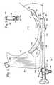
- FIG. 1is a side, elevation view of a preferred embodiment of an instrument made in accordance with the invention shown carrying an endotracheal tube.
- FIG. 2is a front elevation view of the instrument shown in FIG. 1 with the endotracheal tube removed for clarity.
- FIG. 3is a bottom plan view of the instrument of FIG. 1
- FIG. 4is a top plan view of the instrument of FIG. 1 .
- FIG. 5is a cross section taken about line 5 — 5 of FIG. 1 .
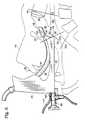
- FIG. 6is a side view of the instrument of FIG. 1 shown inserted into the mouth of a patient.
- FIG. 7is a side, elevation view of a second alternative preferred embodiment of an instrument made in accordance with the invention shown carrying an endotracheal tube.
- FIG. 8is a side, elevation view of the instrument of FIG. 7 shown inserted into the mouth of a patient.
- FIG. 9is a side, elevation view of a third alternative preferred embodiment of an instrument made in accordance with the invention.
- FIG. 10is a side, elevation view of the instrument of FIG. 9 shown inserted into the mouth of a patient.
- FIG. 11Ais a block diagram of an exemplar viewing arrangement.
- FIG. 11Bis a block diagram of an alternative preferred exemplar viewing arrangement.
- FIG. 12is a schematic electrical diagram of a possible viewer defogging element assembly for use on the instrument.
- FIG. 13is a side, elevation view of the instrument of FIG. 7 having a viewer defogging element assembly of FIG. 12 operably secured thereto.
- FIGS. 1-13An improved intubation instrument in accordance with preferred embodiments of the present invention is shown in FIGS. 1-13.
- FIGS. 1-6show a first preferred embodiment
- FIGS. 7, 8 and 11 A-Bshow a second preferred embodiment
- FIGS. 9 and 10show a third preferred embodiment.
- common elements between these three embodimentsare like numbered.
- a first preferred embodiment of an intubation instrument made and used in accord with the present inventionincludes a body 20 that generally comprises an elongated arm 22 with integrally attached handle 24 .
- the instrumentis preferably formed from metal or rigid plastic that can withstand sterilization.
- the instrument armhas a distal end 26 that is inserted into the mouth 30 of a patient 28 .
- the instrumentis inserted while the patient is recumbent, face-up, with the head tipped slightly backwardly, supported in what is known as the sniffing position.
- the sniffing positionis what is known as the sniffing position.
- the instrumentis inserted, distal end 26 first, through the patient's mouth 30 .
- the distal end of the endotracheal tube 40resides in the pharynx 32 .
- individual portions of the pharynx 32have become more commonly referred by those skilled in the art as the nasopharynx 32 a (FIG. 6 ), the oropharynx 32 b (FIG. 6 ), and the laryngopharynx 32 c (FIG. 6 ).
- the endotracheal tube 40resides in the laryngopharynx 32 c (FIG. 6 ).
- the patient's epiglottis 34is supported by the instrument in a manner to expose the glottis 36 .
- the instrumentprovides for the telescopically observed advance of the leading end 38 of an endotracheal tube 40 through the glottis 36 , into the larynx 42 adjacent to the vocal cords 44 .
- an endotracheal tube 40permits air to be conducted to and from an incapacitated patient.
- the present instrumentincludes a number of features that greatly increase the ease with which the instrument and tube 40 can be properly located and continuously observed via a telescope or other optic device.
- the arm 22 of the instrumentis configured to define in the handle 24 and on its anterior surface 46 a guide path for the smooth advance of the tube 40 relative to the inserted instrument.
- the anterior surface 46 of the instrumentis, as shown in FIG. 6, that facing the lower jaw 48 of the intubated patient.
- the guide pathincludes a portion consisting of a channel 50 (FIG. 1) that is formed through the handle 24 .
- the handle 24extends in a generally perpendicular orientation relative to the elongated arm 22 .
- the channel 50extends through the handle 24 at a direction that is generally oblique to the length of the handle 24 and to the arm 22 .
- the channel orientation 50is such that after the leading end of the tube 40 is advanced through the channel 50 , it emerges to contact the anterior surface 46 of the instrument at an acute angle 52 to slide along that surface toward the distal end 26 of the instrument.
- the opposing anterior side edges 54are gradually built up to define, in combination with the anterior surface part between the edges 54 a groove 56 that is generally curved in cross section, as best shown in FIG. 5 .
- the radius of curvature of the groove 56generally conforms to the outside diameter of the tube 40 .
- the side edges 54terminate in a loop 60 that is part of the instrument and protrudes from the distal end 26 of the instrument at an angle 55 (FIG. 1) of about 45 degrees relative to the length of the arm 22 .
- the loopdefines an elongated opening 64 through which extends the leading end 38 of the tube 40 .
- an endotracheal tube 40 used with the preferred embodiment of the instrumentis formed of flexible plastic tubing.
- One such tubeis that manufactured by Mallinckrodt, Inc. of St. Louis Mo., under the trademark Mallinckrodt.
- the tubeis constructed to assume a curved configuration when relaxed, although it is readily deformed as needed.
- the loop 60is configured to permit the leading end 38 of the tube 40 to approach its curved, relaxed configuration as it passes through and out of the loop 60 .
- the elongated opening 64(elongated, that is, in the direction away from the anterior surface of the arm 22 , as shown in FIGS. 2 and 5) permits the flexible tube 40 to resile away from the distal end 26 of the arm 22 to seat against the underside 66 of the loop 60 , as shown in FIG. 1 .
- This underside 66is curved to conform to the outside diameter of the tube, thereby providing, in a manner similar to the above-mentioned groove 56 , precise and smooth guidance of the tube through the loop 60 .
- the loopmakes up another part of the above mentioned guide path.
- the loop 60includes a surface 68 that bears against the patient's epiglottis 34 when the instrument is fully inserted. As a result, the epiglottis 34 and surrounding tissue are held by the instrument in a position where they do not occlude the glottis 36 .
- a guard 70extends from the bottom of the instrument arm 22 at the distal end thereof.
- the guardis an extension of the arm 22 and is angled upwardly (as viewed in FIGS. 1 and 6) to present an underlying surface that acts like a skid upon insertion of the instrument to permit the distal end of the instrument to be advanced against the patient's tissue without damage to the tissue.
- the guard 70reduces the effort needed to insert the device, while protecting the patient's tissue.
- the guard 70serves to prevent the tissue in the pharynx 32 from contacting the distal end 26 of the arm 22 and obstructing the view available to a viewer that is carried by the instrument.
- a telescope 80is shown.
- the telescope 80is one that terminates in a long tubular member having an objective lens at its end 82 .
- the terminus of the telescopefits into a telescope passage 83 that is formed through the arm 22 .
- the telescopealso includes a light post 86 that is mounted to the telescope 80 near the outer end 88 of the passage 83 and that provides illumination to the telescope 80 .
- a suitable telescopeis one having approximately a 25-degree viewing angle; such as manufactured by Henke-Sass, Wolf of America Inc., Southbridge, Mass., as model number 8853.42.
- the instrumentis provided with a clip 90 that is mounted to the arm 22 near the outer end of the passageway 83 .
- the clip 90includes two spaced-apart, arched arms 92 that spread apart slightly to releasably receive between them the generally cylindrical shaped light post 86 as the telescope is slid into position relative to the instrument 22 .
- the clip 90therefore, serves to retain the telescope in the correct location and within the telescope passage 83 during use.
- the arms 92 of the clipengage a radial projection of the telescope (namely, the light post 86 ), the telescope is held against inadvertent rotation out of the desired orientation relative to the arm 22 .
- the arms 92 of the clip 90are resilient and readily move apart to release the light post 86 when the telescope is pulled from the instrument for replacement and cleaning.
- the end 82 of the telescope 80is located at the inner end 84 of the passage 83 when the telescope is installed.
- the guard 70prevents tissue from contacting the end of the telescope. More particularly, the telescope-guarding or tissue-retracting effect of both the loop 60 and the guard 70 has the effect of establishing a clearing 100 (FIG. 6 ), which is a space between the guard and loop, adjacent to the distal end of the instrument and free of view-obstructing tissue.
- the inner end 84 of the telescope passage(hence, the end 82 of an installed telescope) is in this clearing 100 .
- the telescopeis unaffected by tissue that would otherwise obstruct, at least in part, the telescopic view of the advancing, leading end 38 of the endotracheal tube 40 .
- the loop 60 configurationis such that the tube that extends from the loop tends to assume its relaxed, curved shape.
- the leading end 38therefore, tends to veer upwardly (considering FIG. 6) toward the glottis 36 and away from what would be a dangerous entry into the patient's esophagus 43 .
- the tube 40is carried on the anterior surface 46 of the arm 22 , between the patient's lower jaw and the telescope passage 83 . This orientation, in combination with the curved guide path of the tube 40 ensure that the advancing, leading end 38 of the tube remains in the field of view of the telescope (as does the glottis) without crossing near the end 82 of the telescope, which crossing would obscure the view of the tube vis-a-vis the glottis 36 .
- the lens carried in the end 82 of the telescopeis angled upwardly to provide a view in a direction toward the glottis 36 , the movement of the tube end 38 out from beneath the underside of the loop 60 will be nearly parallel to a line defining the center of the field of view of the telescope. It has been found that this relative positioning of the telescope end 82 and tube end 38 greatly enhances viewing of the advancing tube as compared to instruments that went before.
- the preciseness with which the present instrument may be insertedenables one to supply, during insertion, intermittent pulses of air (positive pressure) through the tube 40 to provide immediate respiration to the patient during the insertion process.
- the conventional air or oxygen supply to the tubemay be so connected and controlled during insertion of the instrument.
- the clearing 100would be susceptible to entry of fluids such as blood, exudate, mucus etc, which might be present in instances of neck trauma.
- the arm 22is provided with a passageway 102 having an interior end 104 that opens at the distal end 26 of the instrument, below the inner end 84 of the telescope passage 83 .
- a suction tube 101(FIG. 6) may be attached to a connector 103 that is mounted to the instrument at the outer end of the passageway 102 . Suction is applied for removing any fluid that may begin to accumulate in the clearing 100 . It is noteworthy that the instrument is arranged so that the inner end of the telescope passage is above (FIG.
- suctionwould be applied to the clearing 100 even in the absence of view-obstructing fluids because the application of suction would tend to cool the telescope (which is heated by the light source) or remove vapor that might otherwise tend to condense on the lens of the telescope.
- another passageway 106(FIG. 5) is provided in the arm in a manner that substantially matches the suction passageway 102 .
- This other passagewayis available to hold another suction tube (thus enhancing overall suction of the clearing 100 ) or, alternatively, gas such as oxygen could be directed through this passageway 106 to increase the oxygen content of the glottis area.
- the suction applied by one or both passages 102 , 106provides a vortex of fluid flow in the vicinity of the inner end 84 of the telescope passage, thereby providing a particularly effective way to remove from the telescope end (lens) 82 any fluid contamination, such as blood, that would otherwise obscure the view through the telescope. Thus, the telescope need not be removed for clearing the lens.
- the arrangement of the various components of the instrumentpresents an instrument that is substantially symmetrical about the long axis of the arm and handle.
- the instrumentis readily useable by a right- or left-handed operator.
- the channel 50 in the handle 24may be configured to open on one side of the handle, such as surface 25 (FIG. 1) thereby forming the channel 50 as a groove in the handle.
- the tube 40could be inserted laterally into the channel/groove.
- the groove widthcould be narrowed somewhat, relative to the remainder of the groove, to a width just slightly narrower than the diameter of the flexible tube 40 .
- Such a configurationpermits the tube to be secured by a snapfit into this configuration of the channel.
- a second preferred embodiment of an intubation instrument made and used in accord with the present inventionincludes a body 20 ′ that generally comprises an elongated arm 22 with integrally attached handle 24 , preferably integrally formed from metal or rigid plastic that can withstand sterilization.
- the armincludes an elongate base portion 202 , and a lifter portion 204 extending therefrom as best shown in FIG. 7 .
- the overall length of the armis optimally sized to be positioned within a patient as previously described, and the lifter portion 204 is sized and shaped to have an elongate smooth surface 206 for engaging or lifting the patient's epiglottis 34 (FIG. 8 ), thereby to expose the glottis as best shown in FIG. 8 .
- the epiglottis 34 and surrounding tissueare held by the instrument in a position where they do not occlude the glottis 36 .
- the lifter portion 204is at least approximately 3 centimeters long, and the angle 208 between the base portion 202 and lifter portion 204 is between 5° and 90°, inclusive. More preferably, the length 205 of the lifter portion 204 is between approximately 4 centimeters and 8 centimeters long, and the angle 208 between the lifter portion 204 and base portion 202 is between 30° and 60°. Even more preferably, the length 205 of the lifter portion 204 is approximately the same as the length 207 of the base portion 202 , both of which are approximately 6 centimeters long, and the angle 208 between the lifter and base portions is approximately 45°. Obviously, the overall geometry between the base portion 202 and lifter portion 204 is important for effective operation of the instrument. Proportionately smaller sizes should be used for pediatric applications.
- a viewing devicewhich is preferably a camera 80 ′ operably secured to the instrument, is preferably positioned along the posterior surface of the lifter portion 204 , near the transition portion between the base and lifter portions 202 , 204 , respectively, and aligned to provide a perspective view toward the distal end 210 of the lifter portion 204 .
- the camera 80 ′is mounted to the left side of the instrument when viewed from the handle 25 , thereby permitting passage directly down the midline of the patient's tongue.
- the lifter portion 204protects the camera from being blocked by tissue and debris.
- positioning the camera 80 ′ away from the distal end 210 of the lifter portion 204provides the user with a clear perspective view of the entire area.
- One or more lightswhich are preferably Light Emitting Diodes 212 (“LED”) are preferably positioned along the lifter portion to facilitate operator viewing.
- LEDLight Emitting Diodes
- the use of one or more LED cold light elements in front of the camera lensprovide needed light without producing any heat. Accordingly, unlike traditional expensive Zenon lights typically used on fiber optic laryngoscopes, economical LED lights will not burn sensitive membranes and will not damage the thin plastic cuff found on most endotracheal tubes.
- the camera 80 ′is preferably a Complementary Metal Oxide Semiconductor. (“CMOS”) or Charged Coupled Device (“CCD”) hybrid camera, both of which are more compact, light weight, light sensitive, and economical, than traditional cameras used in such applications.
- CMOSComplementary Metal Oxide Semiconductor.
- CCDCharged Coupled Device
- the camera 80 ′is operably connected to a power source 214 , such as a battery or A/C connection, and suitable related electronics 216 , which are stored in the handle 24 of the instrument.
- a power source 214such as a battery or A/C connection
- suitable related electronics 216which are stored in the handle 24 of the instrument.
- the camera 80 ′is operably connected to a display 218 , either by a direct (FIG. 11B) or remote (FIG. 11A) connection.
- Such remote connectionscan include a transmitter 220 received within the instrument and the display 218 including a receiver 222 for receiving video signals from the transmitter 220 .
- a systemcan include infrared technology or the like.
- the camera 80 ′ and related transmitter 220can also communicate with a display, or other equipment such as remote locations via the evolving industry standard more commonly. known as “bluetooth.” Such communication can also be used to transmit the information via the Internet or the like, thereby facilitating real-time remote incident analysis, advice, assistance, and/or teaching.
- the display 218may be detached from or attached to the instrument, and may also be configured to simultaneously display other relevant information such as the patient's vital signs and the like, thereby facilitating operator use of the instrument.
- the camera 80 ′is secured within a sealed chamber 224 within the arm 22 , thereby protecting it from water, gasses, and chemicals used in sterilization procedures. More preferably, the chamber 224 contains nitrogen gas free from moisture, thereby avoiding undesirable condensation. Preferably, the CMOS or CCD camera body is also sealed.
- a tightly fitted, transparent protective sheathmay be positioned over the assembly to facilitate cleaning and provide sterile multiple use of the device.
- the sheathis tightly fitted over the lens of the camera to prevent it from encumber the view.
- the sheathis a transparent polymer, such as plastic, which sheds mucus and blood, has little tendency to fog during use, and equilibrates rapidly to airway temperature.
- the instrumentmay also include paths (not shown) for transmitting oxygen and/or fluid to the camera lens, thereby assisting clearing and cleaning the lens during operation.
- the embodimentcan also include the guide path, groove and loop for slidably receiving an endotracheal tube 40 as with the first preferred embodiment.
- the instrumentcan be used as a conventional laryngoscope, without providing for receiving therein such an endotracheal tube 40 .
- the arrangement of the various components of the instrumentpresents an instrument that is substantially symmetrical about the long axis of the arm and handle.
- the instrumentis readily useable by a right- or left-handed operator.
- FIGS. 9 and 10a third preferred embodiment of an intubation instrument made and used in accord with the present invention is disclosed. It includes the body 20 ′′ that generally comprises an elongated arm 22 with integrally attached handle 24 of the second preferred embodiment, including the viewer and light. However, the lifter portion 204 of the arm 22 is pivotally secured to the base portion 202 at pivot point 301 as best shown in FIG. 9 .
- a locking mechanism 307such as an actuation lever 300 having a handle 302 at one end extends through a channel 304 in the base portion 202 to pivot the lifter portion 204 about pivot point 301 .
- Detents 306 between the actuation lever and base portionallow a user to select the desired angle 208 between the lifter portion 204 and base portion 202 , and lock that position in place. Accordingly, by manipulating the actuation lever, the optimal angle 208 between the lifter portion 204 and base portion 202 for a particular patient may be selected on site by the practitioner.
- This embodimentcan also include the guide path, groove and loop for slidably receiving an endotracheal tube 40 as with the first preferred embodiment.
- the instrumentcan be. used as a conventional laryngoscope, without providing for receiving therein such a endotracheal tube 40 .
- a defogger assembly 351that defogs the lense of the viewer on an instrument 20 ′ by heating the lense.
- One such structure for heating the lenseincludes thermally-coupling a heating element, such as a resistor 350 or coil, to the lense of the viewer.
- the resistor 350is preferably positioned adjacent to the lense and placed in electrical communication with a power source 214 .
- the components of the defogger assembly, such as the power source 214 , heating element, and related wiring,are contained within the instrument 20 ′, thereby maintaining the portability of the instrument 20 ′.
- the power source 214is a low voltage direct current battery or the like.
- the resistor 350 and currentare selected so as to heat the lense to a desired temperature to permit defogging, while still preventing the resistor from becoming hot enough to burn a patient or damage any components of the instrument.
- the heating elementis regulated so as to maintain an optimal temperature.
- a thermostat operably secured to the defogger assemblycan modulate current from the power source based on the level of detected temperature so as to prevent the heating element from becoming too hot.
- a switch 352is operably secured to the resistor 350 such that power to the heating element may be turned on or off as needed to defog the lense of the viewer by heating the lense.
- the switch 352may be manually controlled as shown in FIGS. 12 and 13, or controlled by internal electronics so as to activate under predetermined conditions.
- the internal electronicscan power the heating element whenever the camera is activated.
- the defogger assembly 351can be activated whenever the light source 212 ′ is activated, for example, by activating light switch 356 .
- FIG. 1shows in dashed lines 110 such an alternative channel that would permit the advance of elongated forceps to the distal end of the instrument to be used, for example, in removing foreign objects from the larynx.
- the defogger assembly 351is shown operably secured to the instrument 20 ′ of the second preferred embodiment, it may be readily adapted to operate effectively on any of the disclosed instruments or their equivalents thereto.
Landscapes
- Health & Medical Sciences (AREA)
- Life Sciences & Earth Sciences (AREA)
- Surgery (AREA)
- Pulmonology (AREA)
- Radiology & Medical Imaging (AREA)
- Biomedical Technology (AREA)
- Biophysics (AREA)
- Nuclear Medicine, Radiotherapy & Molecular Imaging (AREA)
- Optics & Photonics (AREA)
- Pathology (AREA)
- Physiology (AREA)
- Otolaryngology (AREA)
- Engineering & Computer Science (AREA)
- Physics & Mathematics (AREA)
- Heart & Thoracic Surgery (AREA)
- Medical Informatics (AREA)
- Molecular Biology (AREA)
- Animal Behavior & Ethology (AREA)
- General Health & Medical Sciences (AREA)
- Public Health (AREA)
- Veterinary Medicine (AREA)
- Endoscopes (AREA)
Abstract
Description
Claims (20)
Priority Applications (2)
| Application Number | Priority Date | Filing Date | Title |
|---|---|---|---|
| US10/356,705US6655377B2 (en) | 1997-12-01 | 2003-01-30 | Intubation instrument |
| US11/925,868US20080146879A1 (en) | 1997-12-01 | 2007-10-27 | Intubation instrument |
Applications Claiming Priority (9)
| Application Number | Priority Date | Filing Date | Title |
|---|---|---|---|
| US6720597P | 1997-12-01 | 1997-12-01 | |
| US7435598P | 1998-02-10 | 1998-02-10 | |
| US09/060,891US6142144A (en) | 1997-12-01 | 1998-04-15 | Intubation instrument |
| US16871199P | 1999-12-06 | 1999-12-06 | |
| US22333000P | 2000-08-07 | 2000-08-07 | |
| US70450700A | 2000-11-02 | 2000-11-02 | |
| US09/732,129US6543447B2 (en) | 1997-12-01 | 2000-12-06 | Intubation instrument |
| US35228302P | 2002-01-30 | 2002-01-30 | |
| US10/356,705US6655377B2 (en) | 1997-12-01 | 2003-01-30 | Intubation instrument |
Related Parent Applications (1)
| Application Number | Title | Priority Date | Filing Date |
|---|---|---|---|
| US09/732,129Continuation-In-PartUS6543447B2 (en) | 1997-12-01 | 2000-12-06 | Intubation instrument |
Related Child Applications (1)
| Application Number | Title | Priority Date | Filing Date |
|---|---|---|---|
| US09/060,891ContinuationUS6142144A (en) | 1997-12-01 | 1998-04-15 | Intubation instrument |
Publications (2)
| Publication Number | Publication Date |
|---|---|
| US20030168059A1 US20030168059A1 (en) | 2003-09-11 |
| US6655377B2true US6655377B2 (en) | 2003-12-02 |
Family
ID=29554613
Family Applications (1)
| Application Number | Title | Priority Date | Filing Date |
|---|---|---|---|
| US10/356,705Expired - LifetimeUS6655377B2 (en) | 1997-12-01 | 2003-01-30 | Intubation instrument |
Country Status (1)
| Country | Link |
|---|---|
| US (1) | US6655377B2 (en) |
Cited By (89)
| Publication number | Priority date | Publication date | Assignee | Title |
|---|---|---|---|---|
| US20040215061A1 (en)* | 2003-04-28 | 2004-10-28 | Zebadiah Kimmel | Visualization stylet for endotracheal intubation |
| US20050224079A1 (en)* | 2004-04-07 | 2005-10-13 | Green Philip A | Variable size endotracheal tube |
| US20050279355A1 (en)* | 1999-05-04 | 2005-12-22 | Loubser Paul G | Superglottic and peri-laryngeal apparatus having video components for structural visualization and for placement of supraglottic, intraglottic, tracheal and esophageal conduits |
| US20060025650A1 (en)* | 2002-10-03 | 2006-02-02 | Oren Gavriely | Tube for inspecting internal organs of a body |
| US20060063976A1 (en)* | 2004-09-03 | 2006-03-23 | Sightline Technologies Ltd. | Optical head for endoscope |
| US20060242946A1 (en)* | 2005-04-29 | 2006-11-02 | Arvin Technologies, Inc. | Method and apparatus for supplying air to emission abatement device by use of turbocharger |
| US20070049794A1 (en)* | 2005-09-01 | 2007-03-01 | Ezc Medical Llc | Visualization stylet for medical device applications having self-contained power source |
| US20070058970A1 (en)* | 2005-09-13 | 2007-03-15 | Spaulding James R | Vision-assisted hand tools |
| US20070068530A1 (en)* | 2004-11-19 | 2007-03-29 | Pacey John A | Secretion clearing ventilation catheter and airway management system |
| US20070106117A1 (en)* | 2005-10-24 | 2007-05-10 | Pentax Corporation | Intubation assistance apparatus |
| US20070137651A1 (en)* | 2005-12-16 | 2007-06-21 | Ezc Medical Llc | Visualization esophageal-tracheal airway apparatus and methods |
| US20070162095A1 (en)* | 2006-01-06 | 2007-07-12 | Ezc Medical Llc | Modular visualization stylet apparatus and methods of use |
| US20070175482A1 (en)* | 2006-01-27 | 2007-08-02 | Ezc Medical Llc | Apparatus for introducing an airway tube into the trachea having visualization capability and methods of use |
| US20070215162A1 (en)* | 2005-12-16 | 2007-09-20 | Ezc Medical Llc | Visualization airway apparatus and methods for selective lung ventilation |
| US20080029100A1 (en)* | 2005-12-16 | 2008-02-07 | Ezc Medical Llc | Visualization laryngeal airway apparatus and methods of use |
| US20080091064A1 (en)* | 2006-10-17 | 2008-04-17 | Vadim Laser | Portable endoscope for intubation |
| US20080188717A1 (en)* | 2007-02-07 | 2008-08-07 | Tien-Sheng Chen | Double-Slope Prism Module for Laryngoscope |
| US20080216826A1 (en)* | 2007-08-07 | 2008-09-11 | Searete Llc, A Limited Liability Corporation Of The State Of Delaware | Airway imaging system |
| US20080216840A1 (en)* | 2007-03-06 | 2008-09-11 | Searete Llc, A Limited Liability Corporation Of The State Of Delaware | Imaging via the airway |
| US20080249355A1 (en)* | 2007-04-04 | 2008-10-09 | Dashiell Birnkrant | Video endoscopic device with detachable control circuit |
| US20080249370A1 (en)* | 2007-04-04 | 2008-10-09 | Dashiell Birnkrant | Video blade laryngoscope |
| US20090024018A1 (en)* | 2007-08-07 | 2009-01-22 | Searete Llc, A Limited Liability Corporation Of The State Of Delaware | Anatomical imaging system |
| US20090032016A1 (en)* | 2007-08-04 | 2009-02-05 | John Adam Law | Airway intubation device |
| US20090125002A1 (en)* | 2005-07-25 | 2009-05-14 | Km Technologies | Device and method for placing within a patient an enteral tube after endotracheal intubation |
| US20090171155A1 (en)* | 2007-12-27 | 2009-07-02 | Koichi Tsunoda | Oral cavity insertion instrument and pharyngoscope apparatus |
| WO2009103075A1 (en)* | 2008-02-15 | 2009-08-20 | Verathon Inc. | Single-use multi-platform intubation and surgical apparatus |
| US20090209826A1 (en)* | 2008-01-09 | 2009-08-20 | Ezc Medical Llc | Intubation systems and methods |
| US20090209816A1 (en)* | 2005-12-19 | 2009-08-20 | Per Gorm Gunther Nielsen | Induction coil sensing |
| US20090299146A1 (en)* | 2005-12-09 | 2009-12-03 | Aircraft Medical Limited | Laryngoscope Blade |
| US20090322867A1 (en)* | 2006-08-07 | 2009-12-31 | Innovative Medical Devices , Inc | System to aid in the positioning, confirmation and documentation of an endotracheal tube |
| US20100108060A1 (en)* | 2006-06-01 | 2010-05-06 | Truphatek International Ltd | Hand operated articulated intubation stylet |
| US20100249513A1 (en)* | 2009-03-31 | 2010-09-30 | Jay Tydlaska | Laryngoscope and system |
| US20100254646A1 (en)* | 2007-08-31 | 2010-10-07 | Hans Wendeberg | Bearing, and Methods of Handling the Bearing |
| US20100261968A1 (en)* | 2007-06-12 | 2010-10-14 | University Hospitals Of Cleveland | Apparatus and method for airway management |
| US20100312059A1 (en)* | 2007-08-28 | 2010-12-09 | Aircraft Medical Limited | Laryngoscope |
| US20110060190A1 (en)* | 2007-08-07 | 2011-03-10 | Truphatek International Ltd. | Laryngoscope apparatus with enhanced viewing capability |
| US20110077466A1 (en)* | 2009-09-25 | 2011-03-31 | Spectrum Health Innovations, LLC | Laryngoscope guide and related method of use |
| US7921847B2 (en) | 2005-07-25 | 2011-04-12 | Intubix, Llc | Device and method for placing within a patient an enteral tube after endotracheal intubation |
| USD637717S1 (en) | 2009-10-02 | 2011-05-10 | Indian Ocean Medical Inc. | Laryngoscope |
| WO2011060447A1 (en) | 2009-11-16 | 2011-05-19 | Verathon Inc. | Channel laryngoscopes and systems |
| WO2011060445A1 (en) | 2009-11-16 | 2011-05-19 | Verathon Inc. | Telemedicine systems and methods |
| US7946981B1 (en)* | 2003-10-23 | 2011-05-24 | Anthony Cubb | Two-piece video laryngoscope |
| US20110144436A1 (en)* | 2009-12-11 | 2011-06-16 | University Hospitals Of Cleveland | Airway management |
| USD650476S1 (en) | 2011-05-25 | 2011-12-13 | Truphatek International Ltd. | Hand operated articulated intubation stylet |
| US20120029293A1 (en)* | 2010-07-30 | 2012-02-02 | Vasan Nilesh R | Disposable, Self-Contained Laryngoscope and Method of Using Same |
| US20120059223A1 (en)* | 2009-03-03 | 2012-03-08 | Mcgrath Matthew John Ross | Laryngscope insertion section with tube guide |
| US8157919B2 (en) | 2009-02-06 | 2012-04-17 | Endoclear, Llc | Methods for removing debris from medical tubes |
| USD663026S1 (en) | 2010-09-01 | 2012-07-03 | King Systems Corporation | Visualization instrument |
| US20120167882A1 (en)* | 2010-12-29 | 2012-07-05 | Nellcor Puritan Bennett Llc | Temperature monitoring and control devices for tracheal tubes |
| CN102580217A (en)* | 2012-04-11 | 2012-07-18 | 广州耀远实业有限公司 | Novel laryngoscopic lens |
| US8381345B2 (en) | 2009-02-06 | 2013-02-26 | Endoclear, Llc | Devices for cleaning endotracheal tubes |
| US8394016B1 (en) | 2009-07-02 | 2013-03-12 | Bruce Cabot Arné | Illuminated airway article |
| US8414481B2 (en) | 2010-06-24 | 2013-04-09 | General Electric Company | Laryngoscope |
| US8512234B2 (en) | 2011-04-07 | 2013-08-20 | Truphatek International Ltd. | Laryngoscope assembly with enhanced viewing capability |
| USD695401S1 (en) | 2011-12-23 | 2013-12-10 | Karl Storz Gmbh & Co. Kg | Laryngoscope |
| US20140180006A1 (en)* | 2012-11-13 | 2014-06-26 | The Curators Of The University Of Missouri | Endoscopic-Enabled Tongue Depressor and Associated Method of Use |
| US20140238390A1 (en)* | 2014-05-05 | 2014-08-28 | Deye Wei | Intubation device and method |
| USD716841S1 (en) | 2012-09-07 | 2014-11-04 | Covidien Lp | Display screen with annotate file icon |
| USD717340S1 (en) | 2012-09-07 | 2014-11-11 | Covidien Lp | Display screen with enteral feeding icon |
| USD735343S1 (en) | 2012-09-07 | 2015-07-28 | Covidien Lp | Console |
| US9107628B2 (en) | 2012-10-12 | 2015-08-18 | Karl Storz Gmbh & Co. Kg | Video laryngoscope with disposable blade |
| US9179831B2 (en) | 2009-11-30 | 2015-11-10 | King Systems Corporation | Visualization instrument |
| US9198835B2 (en) | 2012-09-07 | 2015-12-01 | Covidien Lp | Catheter with imaging assembly with placement aid and related methods therefor |
| US9226651B2 (en) | 2007-08-28 | 2016-01-05 | Aircraft Medical Limited | Laryngoscope insertion section |
| US20160038008A1 (en)* | 2014-08-08 | 2016-02-11 | Wm & Dg, Inc. | Medical devices and methods of placement |
| US9289114B2 (en)* | 2010-07-30 | 2016-03-22 | Nilesh R. Vasan | Disposable, self-contained laryngoscope and method of using same |
| US9295798B2 (en) | 2013-10-09 | 2016-03-29 | Danny Martin Sartore | Laryngoscopic device with drug and oxygen delivery conduits |
| US9357905B2 (en) | 2012-06-01 | 2016-06-07 | Robert Molnar | Airway device, airway assist device and the method of using same |
| US9415179B2 (en) | 2012-06-01 | 2016-08-16 | Wm & Dg, Inc. | Medical device, and the methods of using same |
| US9433339B2 (en) | 2010-09-08 | 2016-09-06 | Covidien Lp | Catheter with imaging assembly and console with reference library and related methods therefor |
| US9445714B2 (en) | 2010-03-29 | 2016-09-20 | Endoclear Llc | Endotracheal tube coupling adapters |
| US9517184B2 (en) | 2012-09-07 | 2016-12-13 | Covidien Lp | Feeding tube with insufflation device and related methods therefor |
| US10004863B2 (en) | 2012-12-04 | 2018-06-26 | Endoclear Llc | Closed suction cleaning devices, systems and methods |
| US10016575B2 (en) | 2014-06-03 | 2018-07-10 | Endoclear Llc | Cleaning devices, systems and methods |
| US10149602B2 (en) | 2011-07-11 | 2018-12-11 | Ambu A/S | Endobronchial tube with integrated image sensor and a cleaning nozzle arrangement |
| US10165937B2 (en) | 2012-11-13 | 2019-01-01 | Karl Storz Imaging, Inc. | Configurable anesthesia safety system |
| US10165938B2 (en) | 2012-11-13 | 2019-01-01 | Karl Storz Imaging, Inc. | Configurable medical video safety system |
| US10245402B2 (en) | 2011-07-11 | 2019-04-02 | Ambu A/S | Endobronchial tube with integrated image sensor |
| US10512394B2 (en) | 2013-09-26 | 2019-12-24 | The Curators Of The University Of Missouri | Endoscopic-enabled mouth gag and associated method of use |
| USD876625S1 (en) | 2018-08-07 | 2020-02-25 | Adroit Surgical, Llc | Laryngoscope |
| US10653307B2 (en) | 2018-10-10 | 2020-05-19 | Wm & Dg, Inc. | Medical devices for airway management and methods of placement |
| US10722110B2 (en) | 2014-08-08 | 2020-07-28 | Wm & Dg, Inc. | Medical devices and methods of placement |
| US10722322B2 (en) | 2010-03-29 | 2020-07-28 | Endoclear Llc | Distal airway cleaning devices |
| USD921185S1 (en)* | 2019-01-24 | 2021-06-01 | Sridhar R. Musuku | Intubation device |
| US11051682B2 (en) | 2017-08-31 | 2021-07-06 | Wm & Dg, Inc. | Medical devices with camera and methods of placement |
| US11147442B2 (en) | 2014-08-08 | 2021-10-19 | Wm & Dg, Inc. | Medical devices and methods of placement |
| US11202561B2 (en) | 2014-08-08 | 2021-12-21 | Wm & Dg, Inc. | Medical devices and methods of placement |
| US11497394B2 (en) | 2020-10-12 | 2022-11-15 | Wm & Dg, Inc. | Laryngoscope and intubation methods |
| US12257387B2 (en) | 2018-10-10 | 2025-03-25 | Wm & Dg, Inc. | Medical devices for airway management and methods of placement |
Families Citing this family (19)
| Publication number | Priority date | Publication date | Assignee | Title |
|---|---|---|---|---|
| AT501561B1 (en)* | 2003-09-01 | 2008-03-15 | Schunk Metall & Kunststoff | LARYNGOSCOPE |
| EP1868486A4 (en)* | 2005-04-01 | 2012-11-14 | Verathon Medical Canada Ulc | Video retractor |
| AT503096B1 (en)* | 2005-12-16 | 2009-04-15 | Carl Reiner Gmbh | JET ENDOSKOP |
| JP4611193B2 (en)* | 2005-12-27 | 2011-01-12 | オリンパスメディカルシステムズ株式会社 | Endoscope device |
| WO2007085664A1 (en)* | 2006-01-24 | 2007-08-02 | Page 65, S.L. | Luminous optical laryngoscope |
| US20070195539A1 (en)* | 2006-02-21 | 2007-08-23 | Karl Storz Gmbh & Co. Kg | Ultra wide band wireless optical endoscopic device |
| ES2284421B1 (en)* | 2007-07-10 | 2009-04-01 | Prodol Meditec, S.A. | OPTICAL SYSTEM FOR LARYNGOSCOPE AND LARYNGOSCOPE. |
| WO2009051698A2 (en)* | 2007-10-12 | 2009-04-23 | Beth Israel Deaconess Medical Center | Catheter guided endotracheal intubation |
| GB0819942D0 (en)* | 2008-10-30 | 2008-12-10 | Indian Ocean Medical Inc | Guiding device for use with laryngoscope |
| US9078615B2 (en) | 2008-10-30 | 2015-07-14 | Indian Ocean Medical Inc. | Guiding device for use with laryngoscope |
| GB0901945D0 (en)* | 2009-02-09 | 2009-03-11 | Young Peter J | Visualized suction catheter |
| GB0906688D0 (en) | 2009-04-17 | 2009-06-03 | Indian Ocean Medical Inc | Laryngoscope |
| GB0915107D0 (en) | 2009-08-28 | 2009-10-07 | Indian Ocean Medical Inc | Laryngoscope |
| EP3150105B1 (en)* | 2013-03-19 | 2018-09-05 | Olympus Corporation | Endoscope apparatus |
| WO2017192897A1 (en)* | 2016-05-06 | 2017-11-09 | Cardioscout Solutions, Inc. | Access devices and methods for treatment of medical conditions and delivery of injectables |
| EP3664686A4 (en) | 2017-08-07 | 2021-04-21 | Weinmann, Maxwell | LARYNGOSCOPE |
| JP6986266B2 (en)* | 2017-11-14 | 2021-12-22 | ジーニアルライト株式会社 | Body fluid analyzer |
| EP3854290A1 (en)* | 2020-01-24 | 2021-07-28 | Universität Zürich | Tip light laryngoscope for trans-tissue illumination |
| WO2022026751A1 (en)* | 2020-07-29 | 2022-02-03 | University Of Miami | Suction device for periglottic suctioning |
Citations (38)
| Publication number | Priority date | Publication date | Assignee | Title |
|---|---|---|---|---|
| US3771514A (en) | 1971-06-29 | 1973-11-13 | Concept | Laryngoscope |
| US4114609A (en) | 1975-07-16 | 1978-09-19 | Moses John A | Laryngoscope |
| US4126127A (en) | 1976-09-27 | 1978-11-21 | May Laurence M | Suctioning/oxygenating laryngoscope blade |
| US4360008A (en) | 1980-09-02 | 1982-11-23 | Corazzelli Jr Frank G | Laryngoscope |
| US4573451A (en) | 1984-11-08 | 1986-03-04 | Jack Bauman | Laryngoscope blade with a bendable tip |
| US4592343A (en) | 1979-11-28 | 1986-06-03 | The Upsher Laryngoscope Corp. | Laryngoscope |
| US4793327A (en) | 1986-01-21 | 1988-12-27 | Frankel Alfred R | Device for opening a patient's airway during automatic intubation of the trachea |
| US4832004A (en) | 1986-04-16 | 1989-05-23 | Richard Wolf, Gmbh | Laryngoscope for laser treatment |
| US4846153A (en) | 1988-06-10 | 1989-07-11 | George Berci | Intubating video endoscope |
| US4947896A (en) | 1988-11-04 | 1990-08-14 | Bartlett Robert L | Laryngoscope |
| US4982729A (en) | 1989-02-10 | 1991-01-08 | Wu Tzu Lang | Rigid fiberoptic intubating laryngoscope |
| US5003962A (en) | 1989-05-10 | 1991-04-02 | Choi Jay J | Laryngoscope with double-angle blade |
| US5016614A (en) | 1985-11-07 | 1991-05-21 | Macallister Niall P | Endotracheal intubation apparatus |
| US5038766A (en) | 1989-11-08 | 1991-08-13 | Parker Jeffrey D | Blind orolaryngeal and oroesophageal guiding and aiming device |
| US5042469A (en) | 1987-03-24 | 1991-08-27 | Augustine Medical, Inc. | Tracheal intubation guide |
| US5095888A (en) | 1990-07-09 | 1992-03-17 | Circon Corporation | Intubating stylet for a laryngoscope |
| US5174283A (en) | 1989-11-08 | 1992-12-29 | Parker Jeffrey D | Blind orolaryngeal and oroesophageal guiding and aiming device |
| US5183031A (en) | 1991-05-13 | 1993-02-02 | Rossoff Leonard J | Fiberoptic intubating laryngoscope |
| US5203320A (en) | 1987-03-24 | 1993-04-20 | Augustine Medical, Inc. | Tracheal intubation guide |
| US5261392A (en) | 1992-04-03 | 1993-11-16 | Achi Corporation | Laryngoscope with interchangeable fiberoptic assembly |
| US5329940A (en) | 1990-02-14 | 1994-07-19 | Adair Edwin Lloyd | Endotracheal tube intubation assist device |
| US5381787A (en) | 1990-05-04 | 1995-01-17 | Bullard; James R. | Extendable and retractable laryngoscope |
| US5431152A (en) | 1993-09-21 | 1995-07-11 | Flam; Gary H. | Oral fiberoptic intubating apparatus and method |
| US5443058A (en) | 1989-05-26 | 1995-08-22 | Ough; Yon D. | Blade for telescopic laryngoscope |
| US5498231A (en) | 1994-03-07 | 1996-03-12 | Franicevic; Klaus | Intubating laryngoscope |
| US5513627A (en) | 1995-01-27 | 1996-05-07 | Flam; Gary H. | Esophageal tracheal intubator airway |
| US5551946A (en) | 1994-05-17 | 1996-09-03 | Bullard; James R. | Multifunctional intubating guide stylet and laryngoscope |
| US5603688A (en) | 1995-04-24 | 1997-02-18 | Upsher Laryngoscope Corporation | Laryngoscope including an upwardly curved blade having a downwardly directed tip portion |
| US5645519A (en) | 1994-03-18 | 1997-07-08 | Jai S. Lee | Endoscopic instrument for controlled introduction of tubular members in the body and methods therefor |
| US5676635A (en) | 1995-08-30 | 1997-10-14 | Levin; Bruce | Instrument for insertion of an endotracheal tube |
| US5776052A (en)* | 1996-12-19 | 1998-07-07 | Callahan; Patrick C. | Laryngoscope adapted to position and advance a fiberoptic bronchoscope |
| US5800344A (en) | 1996-10-23 | 1998-09-01 | Welch Allyn, Inc. | Video laryngoscope |
| WO1998041137A1 (en) | 1997-03-18 | 1998-09-24 | Parker Medical Limited Partnership | Endoscope viewing system with orotracheal introducing guide |
| US5827178A (en) | 1997-01-02 | 1998-10-27 | Berall; Jonathan | Laryngoscope for use in trachea intubation |
| WO1999027840A1 (en) | 1997-12-01 | 1999-06-10 | Pacey John A | Intubation instrument |
| US6174281B1 (en)* | 1996-02-23 | 2001-01-16 | Arcomedic Ltd. | Laryngoscope |
| US6494828B1 (en)* | 2001-07-23 | 2002-12-17 | Jonathan Berall | Laryngoscope |
| US6543447B2 (en)* | 1997-12-01 | 2003-04-08 | Saturn Biomedical Systems Inc | Intubation instrument |
- 2003
- 2003-01-30USUS10/356,705patent/US6655377B2/ennot_activeExpired - Lifetime
Patent Citations (41)
| Publication number | Priority date | Publication date | Assignee | Title |
|---|---|---|---|---|
| US3771514A (en) | 1971-06-29 | 1973-11-13 | Concept | Laryngoscope |
| US4114609A (en) | 1975-07-16 | 1978-09-19 | Moses John A | Laryngoscope |
| US4126127A (en) | 1976-09-27 | 1978-11-21 | May Laurence M | Suctioning/oxygenating laryngoscope blade |
| US4592343A (en) | 1979-11-28 | 1986-06-03 | The Upsher Laryngoscope Corp. | Laryngoscope |
| US4360008A (en) | 1980-09-02 | 1982-11-23 | Corazzelli Jr Frank G | Laryngoscope |
| US4573451A (en) | 1984-11-08 | 1986-03-04 | Jack Bauman | Laryngoscope blade with a bendable tip |
| US5016614A (en) | 1985-11-07 | 1991-05-21 | Macallister Niall P | Endotracheal intubation apparatus |
| US4793327A (en) | 1986-01-21 | 1988-12-27 | Frankel Alfred R | Device for opening a patient's airway during automatic intubation of the trachea |
| US4832004A (en) | 1986-04-16 | 1989-05-23 | Richard Wolf, Gmbh | Laryngoscope for laser treatment |
| US5042469A (en) | 1987-03-24 | 1991-08-27 | Augustine Medical, Inc. | Tracheal intubation guide |
| US5203320A (en) | 1987-03-24 | 1993-04-20 | Augustine Medical, Inc. | Tracheal intubation guide |
| US4846153A (en) | 1988-06-10 | 1989-07-11 | George Berci | Intubating video endoscope |
| US4947896A (en) | 1988-11-04 | 1990-08-14 | Bartlett Robert L | Laryngoscope |
| US4982729A (en) | 1989-02-10 | 1991-01-08 | Wu Tzu Lang | Rigid fiberoptic intubating laryngoscope |
| US5003962A (en) | 1989-05-10 | 1991-04-02 | Choi Jay J | Laryngoscope with double-angle blade |
| US5443058A (en) | 1989-05-26 | 1995-08-22 | Ough; Yon D. | Blade for telescopic laryngoscope |
| US5038766A (en) | 1989-11-08 | 1991-08-13 | Parker Jeffrey D | Blind orolaryngeal and oroesophageal guiding and aiming device |
| US5174283A (en) | 1989-11-08 | 1992-12-29 | Parker Jeffrey D | Blind orolaryngeal and oroesophageal guiding and aiming device |
| US5339805A (en) | 1989-11-08 | 1994-08-23 | Parker Jeffrey D | Blind orolaryngeal and oroesophageal guiding and aiming device |
| US5329940A (en) | 1990-02-14 | 1994-07-19 | Adair Edwin Lloyd | Endotracheal tube intubation assist device |
| US5381787A (en) | 1990-05-04 | 1995-01-17 | Bullard; James R. | Extendable and retractable laryngoscope |
| US5095888A (en) | 1990-07-09 | 1992-03-17 | Circon Corporation | Intubating stylet for a laryngoscope |
| US5183031A (en) | 1991-05-13 | 1993-02-02 | Rossoff Leonard J | Fiberoptic intubating laryngoscope |
| US5261392A (en) | 1992-04-03 | 1993-11-16 | Achi Corporation | Laryngoscope with interchangeable fiberoptic assembly |
| US5431152A (en) | 1993-09-21 | 1995-07-11 | Flam; Gary H. | Oral fiberoptic intubating apparatus and method |
| US5498231A (en) | 1994-03-07 | 1996-03-12 | Franicevic; Klaus | Intubating laryngoscope |
| US5645519A (en) | 1994-03-18 | 1997-07-08 | Jai S. Lee | Endoscopic instrument for controlled introduction of tubular members in the body and methods therefor |
| US5665052A (en) | 1994-05-17 | 1997-09-09 | Bullard; James Roger | Multifunctional intubating guide stylet and laryngoscope |
| US5551946A (en) | 1994-05-17 | 1996-09-03 | Bullard; James R. | Multifunctional intubating guide stylet and laryngoscope |
| US5513627A (en) | 1995-01-27 | 1996-05-07 | Flam; Gary H. | Esophageal tracheal intubator airway |
| US5603688A (en) | 1995-04-24 | 1997-02-18 | Upsher Laryngoscope Corporation | Laryngoscope including an upwardly curved blade having a downwardly directed tip portion |
| US5676635A (en) | 1995-08-30 | 1997-10-14 | Levin; Bruce | Instrument for insertion of an endotracheal tube |
| US6174281B1 (en)* | 1996-02-23 | 2001-01-16 | Arcomedic Ltd. | Laryngoscope |
| US5800344A (en) | 1996-10-23 | 1998-09-01 | Welch Allyn, Inc. | Video laryngoscope |
| US5776052A (en)* | 1996-12-19 | 1998-07-07 | Callahan; Patrick C. | Laryngoscope adapted to position and advance a fiberoptic bronchoscope |
| US5827178A (en) | 1997-01-02 | 1998-10-27 | Berall; Jonathan | Laryngoscope for use in trachea intubation |
| WO1998041137A1 (en) | 1997-03-18 | 1998-09-24 | Parker Medical Limited Partnership | Endoscope viewing system with orotracheal introducing guide |
| US6142144A (en) | 1997-12-01 | 2000-11-07 | Pacey; John A. | Intubation instrument |
| WO1999027840A1 (en) | 1997-12-01 | 1999-06-10 | Pacey John A | Intubation instrument |
| US6543447B2 (en)* | 1997-12-01 | 2003-04-08 | Saturn Biomedical Systems Inc | Intubation instrument |
| US6494828B1 (en)* | 2001-07-23 | 2002-12-17 | Jonathan Berall | Laryngoscope |
Non-Patent Citations (2)
| Title |
|---|
| Adjustable Laryngo-pharyngoscope, 1 page specification sheet, Richard Wolf GmbH, Circa Apr. 1997. |
| Flexible Laryngoscopes, 1 page specification sheet, Richard Wolf Gmbh, Circa Mar. 1997. |
Cited By (164)
| Publication number | Priority date | Publication date | Assignee | Title |
|---|---|---|---|---|
| US20050279355A1 (en)* | 1999-05-04 | 2005-12-22 | Loubser Paul G | Superglottic and peri-laryngeal apparatus having video components for structural visualization and for placement of supraglottic, intraglottic, tracheal and esophageal conduits |
| US20060025650A1 (en)* | 2002-10-03 | 2006-02-02 | Oren Gavriely | Tube for inspecting internal organs of a body |
| US20040215061A1 (en)* | 2003-04-28 | 2004-10-28 | Zebadiah Kimmel | Visualization stylet for endotracheal intubation |
| US7946981B1 (en)* | 2003-10-23 | 2011-05-24 | Anthony Cubb | Two-piece video laryngoscope |
| US20050224079A1 (en)* | 2004-04-07 | 2005-10-13 | Green Philip A | Variable size endotracheal tube |
| US7694681B2 (en) | 2004-04-07 | 2010-04-13 | Green Philip A | Variable size endotracheal tube |
| US7328701B2 (en) | 2004-04-07 | 2008-02-12 | Green Philip A | Variable size endotracheal tube |
| US20060063976A1 (en)* | 2004-09-03 | 2006-03-23 | Sightline Technologies Ltd. | Optical head for endoscope |
| US8449457B2 (en) | 2004-09-03 | 2013-05-28 | Stryker Gi Services C.V. | Optical head for endoscope |
| US20070068530A1 (en)* | 2004-11-19 | 2007-03-29 | Pacey John A | Secretion clearing ventilation catheter and airway management system |
| US20060242946A1 (en)* | 2005-04-29 | 2006-11-02 | Arvin Technologies, Inc. | Method and apparatus for supplying air to emission abatement device by use of turbocharger |
| US20090125002A1 (en)* | 2005-07-25 | 2009-05-14 | Km Technologies | Device and method for placing within a patient an enteral tube after endotracheal intubation |
| US8863746B2 (en) | 2005-07-25 | 2014-10-21 | Kim Technology Partners, LP | Device and method for placing within a patient an enteral tube after endotracheal intubation |
| US7921847B2 (en) | 2005-07-25 | 2011-04-12 | Intubix, Llc | Device and method for placing within a patient an enteral tube after endotracheal intubation |
| US20070049794A1 (en)* | 2005-09-01 | 2007-03-01 | Ezc Medical Llc | Visualization stylet for medical device applications having self-contained power source |
| US20070058970A1 (en)* | 2005-09-13 | 2007-03-15 | Spaulding James R | Vision-assisted hand tools |
| US7471892B2 (en)* | 2005-09-13 | 2008-12-30 | Gm Global Technology Operations, Inc. | Vision-assisted hand tools |
| US20070106117A1 (en)* | 2005-10-24 | 2007-05-10 | Pentax Corporation | Intubation assistance apparatus |
| US8079951B2 (en)* | 2005-10-24 | 2011-12-20 | Hoya Corporation | Intubation assistance apparatus |
| DE102006050073B4 (en)* | 2005-10-24 | 2016-02-11 | Hoya Corp. | Intubationshilfsgerät |
| US11517193B2 (en) | 2005-12-09 | 2022-12-06 | Covidien Ag | Laryngoscope blade |
| US9066700B2 (en)* | 2005-12-09 | 2015-06-30 | Aircraft Medical Limited | Laryngoscope blade |
| US20150297072A1 (en)* | 2005-12-09 | 2015-10-22 | Aircraft Medical Limited | Laryngoscope blade |
| US9693677B2 (en)* | 2005-12-09 | 2017-07-04 | Aircraft Medical Limited | Laryngoscope blade |
| US20090299146A1 (en)* | 2005-12-09 | 2009-12-03 | Aircraft Medical Limited | Laryngoscope Blade |
| US20070137651A1 (en)* | 2005-12-16 | 2007-06-21 | Ezc Medical Llc | Visualization esophageal-tracheal airway apparatus and methods |
| US20070215162A1 (en)* | 2005-12-16 | 2007-09-20 | Ezc Medical Llc | Visualization airway apparatus and methods for selective lung ventilation |
| US20080029100A1 (en)* | 2005-12-16 | 2008-02-07 | Ezc Medical Llc | Visualization laryngeal airway apparatus and methods of use |
| US8684916B2 (en)* | 2005-12-19 | 2014-04-01 | Techmin Pty Limited | Induction coil sensing |
| US20090209816A1 (en)* | 2005-12-19 | 2009-08-20 | Per Gorm Gunther Nielsen | Induction coil sensing |
| US20070162095A1 (en)* | 2006-01-06 | 2007-07-12 | Ezc Medical Llc | Modular visualization stylet apparatus and methods of use |
| US20070175482A1 (en)* | 2006-01-27 | 2007-08-02 | Ezc Medical Llc | Apparatus for introducing an airway tube into the trachea having visualization capability and methods of use |
| US20100108060A1 (en)* | 2006-06-01 | 2010-05-06 | Truphatek International Ltd | Hand operated articulated intubation stylet |
| US8505531B2 (en) | 2006-06-01 | 2013-08-13 | Truphatek International Ltd. | Hand operated articulated intubation stylet |
| US20090322867A1 (en)* | 2006-08-07 | 2009-12-31 | Innovative Medical Devices , Inc | System to aid in the positioning, confirmation and documentation of an endotracheal tube |
| US8416291B2 (en) | 2006-08-07 | 2013-04-09 | Innovative Medical Devices, Inc. | System to aid in the positioning, confirmation and documentation of an endotracheal tube |
| US20080091064A1 (en)* | 2006-10-17 | 2008-04-17 | Vadim Laser | Portable endoscope for intubation |
| US7976459B2 (en) | 2006-10-17 | 2011-07-12 | Intra L.L.C. | Portable endoscope for intubation |
| US20080188717A1 (en)* | 2007-02-07 | 2008-08-07 | Tien-Sheng Chen | Double-Slope Prism Module for Laryngoscope |
| US20080216840A1 (en)* | 2007-03-06 | 2008-09-11 | Searete Llc, A Limited Liability Corporation Of The State Of Delaware | Imaging via the airway |
| US9386914B2 (en) | 2007-04-04 | 2016-07-12 | Karl Storz Endovision, Inc. | Video endoscopic device with detachable control circuit |
| US8029440B2 (en) | 2007-04-04 | 2011-10-04 | Karl Storz Endovision, Inc. | Video blade laryngoscope |
| US20080249370A1 (en)* | 2007-04-04 | 2008-10-09 | Dashiell Birnkrant | Video blade laryngoscope |
| US20080249355A1 (en)* | 2007-04-04 | 2008-10-09 | Dashiell Birnkrant | Video endoscopic device with detachable control circuit |
| US8419634B2 (en) | 2007-06-12 | 2013-04-16 | University Hospitals Of Cleveland | Apparatus and method for airway management |
| US9326669B2 (en) | 2007-06-12 | 2016-05-03 | University Hospitals Of Cleveland | Airway management |
| US20100261968A1 (en)* | 2007-06-12 | 2010-10-14 | University Hospitals Of Cleveland | Apparatus and method for airway management |
| US9167962B2 (en) | 2007-06-12 | 2015-10-27 | University Hospitals Of Cleveland | Airway management |
| US8495999B2 (en) | 2007-08-04 | 2013-07-30 | John Adam Law | Airway intubation device |
| US9820642B2 (en) | 2007-08-04 | 2017-11-21 | King Systems Corporation | Airway intubation device |
| US20090032016A1 (en)* | 2007-08-04 | 2009-02-05 | John Adam Law | Airway intubation device |
| US20110060190A1 (en)* | 2007-08-07 | 2011-03-10 | Truphatek International Ltd. | Laryngoscope apparatus with enhanced viewing capability |
| US20090024018A1 (en)* | 2007-08-07 | 2009-01-22 | Searete Llc, A Limited Liability Corporation Of The State Of Delaware | Anatomical imaging system |
| US20080216826A1 (en)* | 2007-08-07 | 2008-09-11 | Searete Llc, A Limited Liability Corporation Of The State Of Delaware | Airway imaging system |
| US8251898B2 (en) | 2007-08-07 | 2012-08-28 | Truphatek International Ltd | Laryngoscope apparatus with enhanced viewing capability |
| US10194791B2 (en) | 2007-08-28 | 2019-02-05 | Aircraft Medical Limited | Laryngoscope insertion section |
| US20100312059A1 (en)* | 2007-08-28 | 2010-12-09 | Aircraft Medical Limited | Laryngoscope |
| US10986989B2 (en) | 2007-08-28 | 2021-04-27 | Aircraft Medical Limited | Laryngoscope insertion section |
| US9414743B2 (en) | 2007-08-28 | 2016-08-16 | Aircraft Medical Limited | Laryngoscope |
| US9226651B2 (en) | 2007-08-28 | 2016-01-05 | Aircraft Medical Limited | Laryngoscope insertion section |
| US9662001B2 (en) | 2007-08-28 | 2017-05-30 | Aircraft Medical Limited | Laryngoscope insertion section |
| US20100254646A1 (en)* | 2007-08-31 | 2010-10-07 | Hans Wendeberg | Bearing, and Methods of Handling the Bearing |
| US20090171155A1 (en)* | 2007-12-27 | 2009-07-02 | Koichi Tsunoda | Oral cavity insertion instrument and pharyngoscope apparatus |
| US9078559B2 (en)* | 2007-12-27 | 2015-07-14 | Koichi Tsunoda | Oral cavity insertion instrument and pharyngoscope apparatus |
| US20090209826A1 (en)* | 2008-01-09 | 2009-08-20 | Ezc Medical Llc | Intubation systems and methods |
| US20090264708A1 (en)* | 2008-02-15 | 2009-10-22 | Pacey Jack | Single-use multi-platform intubation and surgical apparatus |
| WO2009103075A1 (en)* | 2008-02-15 | 2009-08-20 | Verathon Inc. | Single-use multi-platform intubation and surgical apparatus |
| US8601633B2 (en) | 2009-02-06 | 2013-12-10 | Endoclear Llc | Cleaning of body-inserted medical tubes |
| US8381345B2 (en) | 2009-02-06 | 2013-02-26 | Endoclear, Llc | Devices for cleaning endotracheal tubes |
| US9386907B2 (en) | 2009-02-06 | 2016-07-12 | Endoclear Llc | Visualization systems and methods |
| US9332891B2 (en) | 2009-02-06 | 2016-05-10 | Endoclear Llc | Tracheostomy visualization |
| US9398837B2 (en) | 2009-02-06 | 2016-07-26 | Endoclear Llc | Methods for confirming placement of endotracheal tubes |
| US8157919B2 (en) | 2009-02-06 | 2012-04-17 | Endoclear, Llc | Methods for removing debris from medical tubes |
| US8458844B2 (en) | 2009-02-06 | 2013-06-11 | Endoclear, Llc | Medical tube cleaning apparatus |
| US9579012B2 (en) | 2009-02-06 | 2017-02-28 | Endoclear Llc | Visualized endotracheal tube placement systems |
| US8468637B2 (en) | 2009-02-06 | 2013-06-25 | Endoclear Llc | Mechanically-actuated endotracheal tube cleaning device |
| US9095286B2 (en) | 2009-02-06 | 2015-08-04 | Endoclear Llc | Body-inserted tube cleaning |
| US10682203B2 (en) | 2009-02-06 | 2020-06-16 | Endoclear Llc | Methods of cleaning endotracheal tubes including light treatment |
| US9962233B2 (en) | 2009-02-06 | 2018-05-08 | Endoclear Llc | Body-inserted tube cleaning |
| US8534287B2 (en) | 2009-02-06 | 2013-09-17 | Endoclear, Llc | Methods for tracheostomy visualization |
| US10441380B2 (en) | 2009-02-06 | 2019-10-15 | Endoclear Llc | Body-inserted tube cleaning |
| US9907624B2 (en) | 2009-02-06 | 2018-03-06 | Endoclear Llc | Body-inserted tube cleaning with suction |
| US8382908B2 (en) | 2009-02-06 | 2013-02-26 | Endoclear, Llc | Methods for cleaning endotracheal tubes |
| US9855111B2 (en) | 2009-02-06 | 2018-01-02 | Endoclear Llc | Methods of removing biofilm from endotracheal tubes |
| US20120059223A1 (en)* | 2009-03-03 | 2012-03-08 | Mcgrath Matthew John Ross | Laryngscope insertion section with tube guide |
| US20100249513A1 (en)* | 2009-03-31 | 2010-09-30 | Jay Tydlaska | Laryngoscope and system |
| US8864657B2 (en) | 2009-03-31 | 2014-10-21 | Magaw, Llc | Laryngoscope and system |
| US8663099B2 (en) | 2009-03-31 | 2014-03-04 | Jay (Jason) Tydlaska | System and method of insertion into an oropharyngeal area |
| US20120169481A1 (en)* | 2009-03-31 | 2012-07-05 | Tydlaska Jay Jason | Wireless control of laryngoscope system |
| US9351633B2 (en)* | 2009-03-31 | 2016-05-31 | Magaw, L.L.C. | Wireless control of laryngoscope system |
| WO2010114867A1 (en)* | 2009-03-31 | 2010-10-07 | Jay Tydlaska | Laryngoscope and system |
| US8394016B1 (en) | 2009-07-02 | 2013-03-12 | Bruce Cabot Arné | Illuminated airway article |
| US8366612B2 (en) | 2009-09-25 | 2013-02-05 | Spectrum Health Innovations, LLC | Laryngoscope guide and related method of use |
| US20110201890A1 (en)* | 2009-09-25 | 2011-08-18 | Spectrum Health Innovations, LLC | Laryngoscope guide and related method of use |
| US20110077466A1 (en)* | 2009-09-25 | 2011-03-31 | Spectrum Health Innovations, LLC | Laryngoscope guide and related method of use |
| USD637717S1 (en) | 2009-10-02 | 2011-05-10 | Indian Ocean Medical Inc. | Laryngoscope |
| USD637716S1 (en) | 2009-10-02 | 2011-05-10 | Indian Ocean Medical Inc. | Blade for a laryngoscope |
| USD637715S1 (en) | 2009-10-02 | 2011-05-10 | Indian Ocean Medical Inc. | Laryngoscope with screen |
| USD637714S1 (en) | 2009-10-02 | 2011-05-10 | Indian Ocean Medical Inc. | Blade for a laryngoscope |
| WO2011060447A1 (en) | 2009-11-16 | 2011-05-19 | Verathon Inc. | Channel laryngoscopes and systems |
| WO2011060445A1 (en) | 2009-11-16 | 2011-05-19 | Verathon Inc. | Telemedicine systems and methods |
| US9179831B2 (en) | 2009-11-30 | 2015-11-10 | King Systems Corporation | Visualization instrument |
| US9854962B2 (en)* | 2009-11-30 | 2018-01-02 | King Systems Corporation | Visualization instrument |
| US20110144436A1 (en)* | 2009-12-11 | 2011-06-16 | University Hospitals Of Cleveland | Airway management |
| US8460184B2 (en)* | 2009-12-11 | 2013-06-11 | University Hospitals Of Cleveland | Airway management |
| US10722322B2 (en) | 2010-03-29 | 2020-07-28 | Endoclear Llc | Distal airway cleaning devices |
| US9445714B2 (en) | 2010-03-29 | 2016-09-20 | Endoclear Llc | Endotracheal tube coupling adapters |
| US8414481B2 (en) | 2010-06-24 | 2013-04-09 | General Electric Company | Laryngoscope |
| US9439560B2 (en) | 2010-06-24 | 2016-09-13 | Carefusion Corporation | Laryngoscope |
| US9386915B2 (en)* | 2010-07-30 | 2016-07-12 | Nilesh R. Vasan | Disposable, self-contained laryngoscope and method of using same |
| US9289114B2 (en)* | 2010-07-30 | 2016-03-22 | Nilesh R. Vasan | Disposable, self-contained laryngoscope and method of using same |
| US11478139B2 (en) | 2010-07-30 | 2022-10-25 | Adroit Surgical, Llc | Disposable, self-contained laryngoscope and method of using same |
| US20120029293A1 (en)* | 2010-07-30 | 2012-02-02 | Vasan Nilesh R | Disposable, Self-Contained Laryngoscope and Method of Using Same |
| USD669172S1 (en) | 2010-09-01 | 2012-10-16 | King Systems Corporation | Visualization instrument |
| USD663026S1 (en) | 2010-09-01 | 2012-07-03 | King Systems Corporation | Visualization instrument |
| US9538908B2 (en) | 2010-09-08 | 2017-01-10 | Covidien Lp | Catheter with imaging assembly |
| US10272016B2 (en) | 2010-09-08 | 2019-04-30 | Kpr U.S., Llc | Catheter with imaging assembly |
| US9433339B2 (en) | 2010-09-08 | 2016-09-06 | Covidien Lp | Catheter with imaging assembly and console with reference library and related methods therefor |
| US9585813B2 (en) | 2010-09-08 | 2017-03-07 | Covidien Lp | Feeding tube system with imaging assembly and console |
| US20120167882A1 (en)* | 2010-12-29 | 2012-07-05 | Nellcor Puritan Bennett Llc | Temperature monitoring and control devices for tracheal tubes |
| US8512234B2 (en) | 2011-04-07 | 2013-08-20 | Truphatek International Ltd. | Laryngoscope assembly with enhanced viewing capability |
| USD650476S1 (en) | 2011-05-25 | 2011-12-13 | Truphatek International Ltd. | Hand operated articulated intubation stylet |
| US10149602B2 (en) | 2011-07-11 | 2018-12-11 | Ambu A/S | Endobronchial tube with integrated image sensor and a cleaning nozzle arrangement |
| US10888679B2 (en) | 2011-07-11 | 2021-01-12 | Ambu A/S | Endobronchial tube with integrated image sensor |
| US10406309B2 (en) | 2011-07-11 | 2019-09-10 | Ambu A/S | Endobronchial tube with integrated image sensor and a cleaning nozzle arrangement |
| US10245402B2 (en) | 2011-07-11 | 2019-04-02 | Ambu A/S | Endobronchial tube with integrated image sensor |
| USD695401S1 (en) | 2011-12-23 | 2013-12-10 | Karl Storz Gmbh & Co. Kg | Laryngoscope |
| CN102580217A (en)* | 2012-04-11 | 2012-07-18 | 广州耀远实业有限公司 | Novel laryngoscopic lens |
| US9357905B2 (en) | 2012-06-01 | 2016-06-07 | Robert Molnar | Airway device, airway assist device and the method of using same |
| US10342944B2 (en) | 2012-06-01 | 2019-07-09 | Wm & Dg, Inc. | Airway device with camera |
| US10279136B2 (en) | 2012-06-01 | 2019-05-07 | Wm & Dg Inc. | Method of opening an airway of a patient by a medical professional in a medical procedure using an airway device |
| US9415179B2 (en) | 2012-06-01 | 2016-08-16 | Wm & Dg, Inc. | Medical device, and the methods of using same |
| USD717340S1 (en) | 2012-09-07 | 2014-11-11 | Covidien Lp | Display screen with enteral feeding icon |
| USD735343S1 (en) | 2012-09-07 | 2015-07-28 | Covidien Lp | Console |
| US9517184B2 (en) | 2012-09-07 | 2016-12-13 | Covidien Lp | Feeding tube with insufflation device and related methods therefor |
| US9198835B2 (en) | 2012-09-07 | 2015-12-01 | Covidien Lp | Catheter with imaging assembly with placement aid and related methods therefor |
| USD716841S1 (en) | 2012-09-07 | 2014-11-04 | Covidien Lp | Display screen with annotate file icon |
| US9107628B2 (en) | 2012-10-12 | 2015-08-18 | Karl Storz Gmbh & Co. Kg | Video laryngoscope with disposable blade |
| US10165937B2 (en) | 2012-11-13 | 2019-01-01 | Karl Storz Imaging, Inc. | Configurable anesthesia safety system |
| US10165938B2 (en) | 2012-11-13 | 2019-01-01 | Karl Storz Imaging, Inc. | Configurable medical video safety system |
| US9888909B2 (en)* | 2012-11-13 | 2018-02-13 | The Curators Of The University Of Missouri | Endoscopic-enabled tongue depressor and associated method of use |
| US20140180006A1 (en)* | 2012-11-13 | 2014-06-26 | The Curators Of The University Of Missouri | Endoscopic-Enabled Tongue Depressor and Associated Method of Use |
| US11173266B2 (en) | 2012-12-04 | 2021-11-16 | Endoclear Llc | Closed suction cleaning devices, systems and methods |
| US10004863B2 (en) | 2012-12-04 | 2018-06-26 | Endoclear Llc | Closed suction cleaning devices, systems and methods |
| US10821249B2 (en) | 2012-12-04 | 2020-11-03 | Endoclear Llc | Closed suction cleaning devices, systems and methods |
| US10512394B2 (en) | 2013-09-26 | 2019-12-24 | The Curators Of The University Of Missouri | Endoscopic-enabled mouth gag and associated method of use |
| US9295798B2 (en) | 2013-10-09 | 2016-03-29 | Danny Martin Sartore | Laryngoscopic device with drug and oxygen delivery conduits |
| US9427543B2 (en)* | 2014-05-05 | 2016-08-30 | Deye Wei | Intubation device and method |
| US20140238390A1 (en)* | 2014-05-05 | 2014-08-28 | Deye Wei | Intubation device and method |
| US10016575B2 (en) | 2014-06-03 | 2018-07-10 | Endoclear Llc | Cleaning devices, systems and methods |
| US10850062B2 (en) | 2014-06-03 | 2020-12-01 | Endoclear Llc | Cleaning devices, systems and methods |
| US10722110B2 (en) | 2014-08-08 | 2020-07-28 | Wm & Dg, Inc. | Medical devices and methods of placement |
| US20160038008A1 (en)* | 2014-08-08 | 2016-02-11 | Wm & Dg, Inc. | Medical devices and methods of placement |
| US11147442B2 (en) | 2014-08-08 | 2021-10-19 | Wm & Dg, Inc. | Medical devices and methods of placement |
| US11202561B2 (en) | 2014-08-08 | 2021-12-21 | Wm & Dg, Inc. | Medical devices and methods of placement |
| US9918618B2 (en)* | 2014-08-08 | 2018-03-20 | Wm & Dg, Inc. | Medical devices and methods of placement |
| US11633093B2 (en) | 2014-08-08 | 2023-04-25 | Wm & Dg, Inc. | Medical devices and methods of placement |
| US11051682B2 (en) | 2017-08-31 | 2021-07-06 | Wm & Dg, Inc. | Medical devices with camera and methods of placement |
| USD876625S1 (en) | 2018-08-07 | 2020-02-25 | Adroit Surgical, Llc | Laryngoscope |
| US10653307B2 (en) | 2018-10-10 | 2020-05-19 | Wm & Dg, Inc. | Medical devices for airway management and methods of placement |
| US11628036B2 (en) | 2018-10-10 | 2023-04-18 | Wm & Dg, Inc. | Medical devices for airway management and methods of placement |
| US12257387B2 (en) | 2018-10-10 | 2025-03-25 | Wm & Dg, Inc. | Medical devices for airway management and methods of placement |
| USD921185S1 (en)* | 2019-01-24 | 2021-06-01 | Sridhar R. Musuku | Intubation device |
| US11497394B2 (en) | 2020-10-12 | 2022-11-15 | Wm & Dg, Inc. | Laryngoscope and intubation methods |
Also Published As
| Publication number | Publication date |
|---|---|
| US20030168059A1 (en) | 2003-09-11 |
Similar Documents
| Publication | Publication Date | Title |
|---|---|---|
| US6655377B2 (en) | Intubation instrument | |
| US20080146879A1 (en) | Intubation instrument | |
| US6142144A (en) | Intubation instrument | |
| US7946981B1 (en) | Two-piece video laryngoscope | |
| US5676635A (en) | Instrument for insertion of an endotracheal tube | |
| US10368732B2 (en) | Airway intubation device | |
| US5845634A (en) | Endoscope viewing system with orotracheal introducing guide | |
| CA2493117C (en) | Laryngoscope with multi-directional eyepiece | |
| US5443058A (en) | Blade for telescopic laryngoscope | |
| US5183031A (en) | Fiberoptic intubating laryngoscope | |
| US5431152A (en) | Oral fiberoptic intubating apparatus and method | |
| US20140275772A1 (en) | Intubation device with video and anatomic stylet steering | |
| US20090264708A1 (en) | Single-use multi-platform intubation and surgical apparatus | |
| WO1995018643A1 (en) | Easy intubator | |
| US5425356A (en) | Telescopic laryngoscope blade | |
| US20200171256A1 (en) | Intubation Systems and Methods | |
| HK1057323B (en) | Intubation instrument | |
| Horton et al. | Fiberoptic and Video Intubating Stylets | |
| AU5435201A (en) | Laryngoscope assembly | |
| HK1078757B (en) | Laryngoscope with multi-directional eyepiece |
Legal Events
| Date | Code | Title | Description |
|---|---|---|---|
| AS | Assignment | Owner name:SATURN BIOMEDICAL SYSTEMS INC., CANADA Free format text:ASSIGNMENT OF ASSIGNORS INTEREST;ASSIGNOR:PACEY, JOHN A.;REEL/FRAME:014065/0618 Effective date:20030508 | |
| FEPP | Fee payment procedure | Free format text:PAYOR NUMBER ASSIGNED (ORIGINAL EVENT CODE: ASPN); ENTITY STATUS OF PATENT OWNER: LARGE ENTITY | |
| FPAY | Fee payment | Year of fee payment:4 | |
| AS | Assignment | Owner name:VERATHON MEDICAL (CANADA) ULC, CANADA Free format text:CHANGE OF NAME;ASSIGNOR:SATURN BIOMEDICAL SYSTEMS ULC;REEL/FRAME:025227/0869 Effective date:20061010 Owner name:SATURN BIOMEDICAL SYSTEMS ULC, CANADA Free format text:MERGER;ASSIGNOR:SATURN BIOMEDICAL SYSTEMS, INC.;REEL/FRAME:025227/0865 Effective date:20060113 | |
| REMI | Maintenance fee reminder mailed | ||
| LAPS | Lapse for failure to pay maintenance fees | ||
| REIN | Reinstatement after maintenance fee payment confirmed | ||
| FEPP | Fee payment procedure | Free format text:PETITION RELATED TO MAINTENANCE FEES FILED (ORIGINAL EVENT CODE: PMFP); ENTITY STATUS OF PATENT OWNER: LARGE ENTITY Free format text:PETITION RELATED TO MAINTENANCE FEES GRANTED (ORIGINAL EVENT CODE: PMFG); ENTITY STATUS OF PATENT OWNER: LARGE ENTITY Free format text:PAT HOLDER NO LONGER CLAIMS SMALL ENTITY STATUS, ENTITY STATUS SET TO UNDISCOUNTED (ORIGINAL EVENT CODE: STOL); ENTITY STATUS OF PATENT OWNER: LARGE ENTITY | |
| FP | Lapsed due to failure to pay maintenance fee | Effective date:20111202 | |
| PRDP | Patent reinstated due to the acceptance of a late maintenance fee | Effective date:20120911 | |
| FPAY | Fee payment | Year of fee payment:8 | |
| STCF | Information on status: patent grant | Free format text:PATENTED CASE | |
| SULP | Surcharge for late payment | ||
| FPAY | Fee payment | Year of fee payment:12 |