US6655014B1 - Device for inserting wires and/or pipes in a tubular, flexible sheath provided with openable overlapping edges - Google Patents
Device for inserting wires and/or pipes in a tubular, flexible sheath provided with openable overlapping edgesDownload PDFInfo
- Publication number
- US6655014B1 US6655014B1US09/913,616US91361601AUS6655014B1US 6655014 B1US6655014 B1US 6655014B1US 91361601 AUS91361601 AUS 91361601AUS 6655014 B1US6655014 B1US 6655014B1
- Authority
- US
- United States
- Prior art keywords
- sleeve
- tubular body
- flexible sheath
- split
- cylindrical tubular
- Prior art date
- Legal status (The legal status is an assumption and is not a legal conclusion. Google has not performed a legal analysis and makes no representation as to the accuracy of the status listed.)
- Expired - Fee Related
Links
Images


Classifications
- H—ELECTRICITY
- H02—GENERATION; CONVERSION OR DISTRIBUTION OF ELECTRIC POWER
- H02G—INSTALLATION OF ELECTRIC CABLES OR LINES, OR OF COMBINED OPTICAL AND ELECTRIC CABLES OR LINES
- H02G1/00—Methods or apparatus specially adapted for installing, maintaining, repairing or dismantling electric cables or lines
- H02G1/06—Methods or apparatus specially adapted for installing, maintaining, repairing or dismantling electric cables or lines for laying cables, e.g. laying apparatus on vehicle
- H02G1/08—Methods or apparatus specially adapted for installing, maintaining, repairing or dismantling electric cables or lines for laying cables, e.g. laying apparatus on vehicle through tubing or conduit, e.g. rod or draw wire for pushing or pulling
- H02G1/085—Methods or apparatus specially adapted for installing, maintaining, repairing or dismantling electric cables or lines for laying cables, e.g. laying apparatus on vehicle through tubing or conduit, e.g. rod or draw wire for pushing or pulling using portable tools
- Y—GENERAL TAGGING OF NEW TECHNOLOGICAL DEVELOPMENTS; GENERAL TAGGING OF CROSS-SECTIONAL TECHNOLOGIES SPANNING OVER SEVERAL SECTIONS OF THE IPC; TECHNICAL SUBJECTS COVERED BY FORMER USPC CROSS-REFERENCE ART COLLECTIONS [XRACs] AND DIGESTS
- Y10—TECHNICAL SUBJECTS COVERED BY FORMER USPC
- Y10T—TECHNICAL SUBJECTS COVERED BY FORMER US CLASSIFICATION
- Y10T29/00—Metal working
- Y10T29/53—Means to assemble or disassemble
- Y10T29/5313—Means to assemble electrical device
- Y10T29/532—Conductor
- Y10T29/53243—Multiple, independent conductors
- Y—GENERAL TAGGING OF NEW TECHNOLOGICAL DEVELOPMENTS; GENERAL TAGGING OF CROSS-SECTIONAL TECHNOLOGIES SPANNING OVER SEVERAL SECTIONS OF THE IPC; TECHNICAL SUBJECTS COVERED BY FORMER USPC CROSS-REFERENCE ART COLLECTIONS [XRACs] AND DIGESTS
- Y10—TECHNICAL SUBJECTS COVERED BY FORMER USPC
- Y10T—TECHNICAL SUBJECTS COVERED BY FORMER US CLASSIFICATION
- Y10T29/00—Metal working
- Y10T29/53—Means to assemble or disassemble
- Y10T29/5313—Means to assemble electrical device
- Y10T29/53257—Means comprising hand-manipulatable implement
- Y—GENERAL TAGGING OF NEW TECHNOLOGICAL DEVELOPMENTS; GENERAL TAGGING OF CROSS-SECTIONAL TECHNOLOGIES SPANNING OVER SEVERAL SECTIONS OF THE IPC; TECHNICAL SUBJECTS COVERED BY FORMER USPC CROSS-REFERENCE ART COLLECTIONS [XRACs] AND DIGESTS
- Y10—TECHNICAL SUBJECTS COVERED BY FORMER USPC
- Y10T—TECHNICAL SUBJECTS COVERED BY FORMER US CLASSIFICATION
- Y10T29/00—Metal working
- Y10T29/53—Means to assemble or disassemble
- Y10T29/5313—Means to assemble electrical device
- Y10T29/53265—Means to assemble electrical device with work-holder for assembly
Definitions
- the present inventionrelates to the technical field concerned with providing a protection for a bundle of pipes, such as pipes for compressed air or refrigerating liquids, wires and/or leads.
- These elementsmay be for, instance electric wires installed on control units of automatic machines, wirings of automobiles or motor vehicles, or cables used to supply power to computers or to data transmission lines, optical fibres, or they may also be the leads used in telephonic lines.
- the present inventionconcerns a device for inserting wires and/or pipes in a tubular, flexible sheath with edges, that can be parted.
- the tapingcan be made by an operator, who spreads and set together the single cables, arranging them parallel one beside another, so as to avoid possible tangling.
- the operatorcan use particular tools, such as clamps or cable terminals, which facilitate the insertion and sliding of the group of wires inside the protection structure.
- a Japanese document No. 7-32273describes a device which inserts taped groups of cables in a tubular flexible sheath having edges that can be parted away, and the operation can be performed in a short time.
- This deviceincludes two mirror-like portions, hinged to one each other and maintained close to each other by a spring.
- Each of these portionsincludes a semi-tubular, longitudinal straight element, having semi-circular section, which is connected to a half-shell, hollow inside and with one end truncated.
- the half-shellis connected with a corresponding outer part of the semi-tubular element.
- the half-shellmerges with the semi-tubular element according to a direction inclined with reference to the longitudinal axis of the semi-tubular element.
- the back parts of the element and shellmatch with each other in a way such that the axial dimension of the semi-tubular element is not reduced and its cross-section is maintained unchanged.
- the two mirror-like portionsare maintained close to each other due to the elastic action of the spring, so that the semi-tubular element of one portion, together with the corresponding semi-tubular element of the other portion, create a cylindrical channel.
- the group of wiresis to be inserted in this cylindrical channel.
- the half-shell of one portion, together with the corresponding half-shell of, the other portiondefine an ogive-like structure, which, is to be slidably fitted into the flexible sheath.
- This ogive-like structureallows to open the edges of the flexible sheath along the split, and make the sheath slide along the path defined by the two connected half-shells toward the portion mating with the semi-tubular elements, i.e. toward the outer surface of the adjacent cylindrical channel.
- each mirror-like portionincludes grasping means, formed by a wing, which is handled by the operator to define two working positions of the device.
- the wingsare close to each other and the two mirror-like portions are open due to the elastic action of the spring, so that the wires can be inserted in the device, i.e. inside the cylindrical channel defined by the two joined semi-tubular elements.
- the wirescan be inserted in the flexible sheath by making this sheath slide about and along the ogive structure, which opens the sheath edges.
- the opened sheath edgesswallow the group of wires by closing one over another.
- the above mentioned grasping meanscan be formed, as described in the Japanese document No. 7-107636, by pliers, which act against the elastic action of the spring, so as to open the two mirror-like portions and define the two working positions of the device.
- the publication PR-B-2761826describes a tool for inserting bundled conductors in split over-sheath.
- the toolhas pointed head, with integral handgrip, separating the sheath edges and guiding conductors in through smooth channels
- the toolhas a pointed flattened head provided at approximately 90 degrees to the head-grip.
- Thisis designed to enter a split over-sheath, which is e.g. textile-based, with one edge overlapping the other. After separation, the edges locate in grooves running along either side of the head.
- the conductor bundleenters, sideways, a channel passing through the head at about 20 degrees to the sheath axis, its surface coated to reduce friction.
- the mirror-like portionsdue to the repeated openings of the mirror-like portions, they can be displaced and not aligned, which can result in hinges damage or spring wearing.
- the object of the inventionis that of providing a device which allows to insert a group of wires or cables in a tubular flexible sheath by simple and immediate operations.
- Another object of the present inventionis to propose a device for inserting wires or cables in a tubular flexible sheath, obtained by a compact, strong and extremely practical structure.
- a further object of the present inventionis to propose a device for inserting wires or cables in a tubular flexible sheath, obtained by a simple technical solution, and which is extremely reliable and cheap.
- a device for inserting wires, cables, pipes in a flexible sheathsaid flexible sheath including a plurality of elements, with a slit made on each said elements having two edges overlap one another in normal condition, so as to define a channel, said device including:
- a cylindrical tubular bodyhaving a front end, a rear end, an upper part and lower part with a longitudinally extending split, and with a rounded, wedge-shaped member merging therewith in said upper part of said cylindrical tubular body and extending in a substantially inclined direction, with reference to the longitudinal axis of said cylindrical tubular body and convergent toward said rear end;
- a sleevehaving circular cross section corresponding to the cross section of said cylindrical tubular body, so that said sleeve can be fitted in the cylindrical tubular body, said sleeve being delimited by two heads, a first head and a second head respectively, with of the sleeve having a longitudinal extension such that said two heads, first and second respectively go in abutment on inner part of enlarged borders made at a front end and at a rear end of said cylindrical tubular body, so as to prevent any longitudinal translation of said sleeve with respect to said cylindrical tubular body, with a split being made along the sleeve and having dimensions equal to the split of the cylindrical tubular body, so that the sleeve can turn inside the cylindrical tubular body between two working positions, first in which the split of the sleeve matches with the split of the tubular body, so that one end of a bundle of wires or cables can be inserted in the device, and second position, in which the split of the tubular body is closed by the s
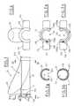
- FIG. 1is a schematic front view of the device for inserting wires and/or pipes in a tubular, flexible sheath with edges that can be parted away, made in accordance with a first embodiment
- FIGS. 1 a and 1 bare schematic front views of the two significant elements of the device of FIG. 1;
- FIGS. 2 a and 2 bare schematic section views, taken along line II—II of FIG. 1, of two working positions of the proposed device;
- FIGS. 3 a and 3 bare schematic section views, taken along line III—III of FIG. 1, in particular, FIG. 3 a of the working position of FIG. 2 a and FIG. 3 b of the working position of FIG. 2 b;
- FIG. 4is a schematic lateral view of the device of FIG. 1;
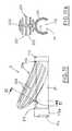
- FIG. 5is a schematic lateral view of the device of FIG. 1 in a particular working step, in which the wires or cables are inserted in a tubular flexible sheath;
- FIG. 6is a schematic section view taken along line VI—VI of FIG. 5;
- FIG. 7is a schematic view of the proposed device according to the direction X indicated in FIG. 5;
- FIG. 8is a schematic section view taken along VIII—VIII of FIG. 1 a;
- FIG. 9is a schematic section view taken along line IX—IX of FIG. 1 b;
- FIG. 10is a schematic, front view of the proposed device for inserting wires and/or pipes in a tubular flexible sheath with edges that can be parted away, made in accordance with an interesting embodiment
- FIGS. 10 a and 10 bare schematic section views taken along line X—X of FIG. 10, showing respectively two working positions of the proposed device;
- FIG. 11is a schematic front view of another interesting embodiment
- FIG. 11 ais a schematic section view taken along line XI—XI of FIG. 11 .
- Dgenerally designates a device for inserting wires or cables and/or pipes C in a tubular flexible sheath F.
- This tubular flexible sheath Fis formed by a combination of a plurality of elements 3 made of plastic material, which can be elastically deformed and are connected one to another.
- These elements 3have each one a slit 3 a made on its back.
- This tubular flexible sheath Fcan be substituted by a pipe (not shown), whose inner walls are corrugated and which has longitudinal splits due to which it can be flexible and, at the same time, double insulated.
- a channel 5is defined inside the sheath F.
- the sheath Fis extremely light and flexible and can fold up defining various paths of the channel 5 .
- the above mentioned device D for inserting cables C in the tubular flexible sheath; Fincludes a first member 1 , which rotates inside a second member 2 .
- this first member 1is formed by a tubular sleeve 11 , whose cross section is circular and which is delimited by two heads, first head 112 and second head 113 , respectively, situated at the ends of this sleeve 11 .
- a split 111extends along the sleeve 11 , from the first head 112 to the second head 113 (FIG. 9 ).
- a group of wires or cables Ccan be introduced through this split 111 .
- the above mentioned second member, 2is formed, as shown in FIG. 1 a , by a tubular cylindrical body 21 , which has, made therealong, a split 211 (FIG. 8 ), whose dimensions are comparable with the dimensions of the split 111 of the sleeve 11 .
- the cross section of the tubular cylindrical body 21is circular and its dimensions allow the sleeve 11 to be fitted in the body 21 .
- the sleeve 11is inserted into the tubular body 21 through the split 211 of the latter.
- first 112 and second 113are located to cover the ends, namely front end 212 and rear end 213 respectively, of the tubular body 21 .
- the sleeve 11can turn inside the tubular cylindrical body 21 , and due to a particular fitting, it is not possible to withdraw the sleeve 11 from the body 21 without breaking the latter.
- a rounded, wedge-shaped member 23 having streamlined profileis connected to the upper section of the cylindrical tubular body 21 , merging therewith.
- the wedge-shape member 23extends along a direction substantially inclined with reference to the cylindrical body longitudinal axis, and convergent therewith in the direction of the rear end 213 of the cylindrical tubular body 21 .
- the flexible sheath Fis set over the wedge-shaped member 23 while moving it the in the direction W, indicated in FIG. 5, so as to open the edges 31 a and 31 b of the elements 3 and increase the cross section of the channel 5 until an aperture is made therein, in the region of the rear end 213 of the tubular body 21 .
- the profile of the wedge-shaped member 23allows to elastically deform, by deflection, the elements 3 of the sheath F, opening their terminal portions 31 a and 31 b.
- edges 31 a and 31 b of the elements 3go beyond the rear end 213 of the cylindrical body 21 , they overlap one another thus resuming their regular configuration.
- the above mentioned first head 112 of the sleeve 11has two diametrical wings 114 , which facilitate handling of the device during the inserting the wires or cables in the flexible sheath.
- this pair of diametrical wings 114allow the operator an easy grip on the device D and practical handling or rotation of the sleeve 11 with respect to the tubular cylindrical body 21 without excessive efforts.
- the above mentioned first head 112has a groove 115 , made along a relative circumference arc on its back and delimited by two abutments, first 115 a and second 115 b , respectively.
- This groove 115has a tooth 116 supported by the front end 212 of the cylindrical tubular body 21 .
- the groove 115slides with respect to the tooth 116 until this tooth stops against one of the two abutments, first 115 a or second 115 b.
- the devicewhen the tooth 116 stops against the first abutment 115 a , the device is in its first working position H 1 , shown in FIGS. 2 a and 3 a , in which the split 111 of the sleeve 11 is aligned with the split 211 of the cylindrical tubular body 21 .
- an extremity of the bundle of wires or cables Ccan be inserted in the device D.
- the devicewhen the tooth 116 stops against the second abutment 115 b , the device is in its second working position H 2 , shown in FIGS. 2 b , 3 b and 5 , in which the split 211 of the cylindrical tubular body 21 is closed by the sleeve 11 .
- the extremity of the bundle of wires or cables Cis blocked inside the device D.
- the device Dpasses from the first working position H 1 to the second working position H 2 (FIGS. 2 a and 2 b ) due to the counterclockwise rotation of the sleeve 11 with respect to the cylindrical tubular body 21 performed by the operator, who acts on the pair of diametrical wings 114 .
- the operatorAfter having grouped and arranged the wires or cables one beside another, the operator sets the device D in the working position H 1 by acting on the diametrical wings 114 , so as to rotate the sleeve 11 with respect to the cylindrical tubular body 21 , until the first abutment 115 a stops against the tooth 116 .
- the split 111 of the sleeve 11is aligned with the split 211 of the cylindrical tubular body 21 .
- the operatorinserts one end of the bundle of wires or cables C inside the cylindrical tubular body 21 through these splits 111 and 211 .
- the operatoracts on the diametrical wings 114 , so as to rotate the sleeve 11 , until the second abutment 115 b stops against the tooth 116 , thus defining the second working position H 2 .
- the end of the bundle of wires or cables Cis closed inside the device D, in particular inside the cylindrical tubular body 21 .
- a first head 112 a of a sleeve 11has bigger longitudinal extension, which makes the device's handling still easier and anatomic.
- the operator's fingerscan completely encircle this head thus facilitating a best gripping of the wings 114 and, at the same time, facilitating the sheath sliding with respect to the device.
- the head 112 ahas no split, and the front end 212 of the cylindrical tubular body 21 has no tooth.
- the device Dpasses from the:first working position H 1 shown in FIG. 10 a , in which the split 111 of the sleeve 11 is aligned with the split 211 of the cylindrical tubular body 21 , to the second working position H 2 shown in FIG. 10 b , in which the split 211 is closed by the sleeve 11 , due to a simple rotation of this sleeve 11 , in clockwise or counterclockwise direction, by 180°.
- a wedge-shaped member 23 a formed by a plurality of wings 231rises outside and over the cylindrical tubular body 21 .
- the wings 231extend downwards in a substantially inclined direction, convergent toward the rear end 213 of this cylindrical tubular body 21 .
- These wings 231supported by a ridge 232 , define a rounded envelope 233 which defines the flexible sheath F sliding path during the working steps relative to the inserting of wires or cables therein.
- the profile of the wings 231allows to elastically deform, by deflection, the elements 3 of the sheath F, opening their edges 31 a and 31 b.
- All the described embodiments of the proposed deviceallow advantageously to insert a bundle of wires or cables in a tubular flexible sheath by simple and immediate operations.
- the proposed deviceis equipped with two elements which define an extremely compact and strong structure guaranteeing high functionality during all the working steps through which the wires or cables are inserted in the flexible sheath.
- the proposed deviceallows a group of wires, cables or leads present in the automatic machines control units, in the electric and electronic equipment for motor vehicles, or cables used for computers power supply, or for data transmission lines, compressed air or cooling liquid pipes, or conductors of the telephone lines, to be inserted in a protecting structure without a previous taping.
- the proposed devicein all its embodiments, allows to insert wires, cables, leads and/or pipes in a protective structure also when they are already installed, wired or bundled.
- the proposed devicein all its embodiments, is obtained by a simple and extremely reliable technical solution, using simple components, which results in reducing the production cost.
Landscapes
- Details Of Indoor Wiring (AREA)
- Supports For Pipes And Cables (AREA)
Abstract
Description
The present invention relates to the technical field concerned with providing a protection for a bundle of pipes, such as pipes for compressed air or refrigerating liquids, wires and/or leads.
These elements, may be for, instance electric wires installed on control units of automatic machines, wirings of automobiles or motor vehicles, or cables used to supply power to computers or to data transmission lines, optical fibres, or they may also be the leads used in telephonic lines.
More particularly, the present invention concerns a device for inserting wires and/or pipes in a tubular, flexible sheath with edges, that can be parted.
In these last years, the continuously growing use of electronics as a control and operating means has determined a relevant increase of the number of electric wires and leads present on an automatic machine, a control unit, or a motor vehicle, etc.
This has implied the increasing need set up more functional wiring and to distribute wires along predetermined protected and safe paths, so as to avoid their possible damages, useless encumbrance or obstacles to normal working of motors or moving mechanical means controlled thereby.
Therefore, during installation of wires and leads, it is fundamental to first tape them and insert them in protective and insulating structures, such as tubular sheaths or raceways.
Moreover, protection and insulation of all wires, leads and/or pipes from the surrounding environment is explicitly required by many security rules currently in force.
At present, the taping can be made by an operator, who spreads and set together the single cables, arranging them parallel one beside another, so as to avoid possible tangling.
After the taping has been completed, the operator inserts the group of cables thus obtained into the above mentioned protection structure.
The operator can use particular tools, such as clamps or cable terminals, which facilitate the insertion and sliding of the group of wires inside the protection structure.
Because of the wires length or due to the particular, flexible and not straight form of protection structures, inserting operation of the taped group of wires results to be extremely difficult.
Thus, this operation requires a lot of manpower and prolongs the working time, resulting in a considerable increase of total installation cost.
A Japanese document No. 7-32273 describes a device which inserts taped groups of cables in a tubular flexible sheath having edges that can be parted away, and the operation can be performed in a short time. This device includes two mirror-like portions, hinged to one each other and maintained close to each other by a spring.
Each of these portions includes a semi-tubular, longitudinal straight element, having semi-circular section, which is connected to a half-shell, hollow inside and with one end truncated. The half-shell is connected with a corresponding outer part of the semi-tubular element. The half-shell merges with the semi-tubular element according to a direction inclined with reference to the longitudinal axis of the semi-tubular element. The back parts of the element and shell match with each other in a way such that the axial dimension of the semi-tubular element is not reduced and its cross-section is maintained unchanged.
The two mirror-like portions are maintained close to each other due to the elastic action of the spring, so that the semi-tubular element of one portion, together with the corresponding semi-tubular element of the other portion, create a cylindrical channel.
The group of wires is to be inserted in this cylindrical channel.
Moreover, the half-shell of one portion, together with the corresponding half-shell of, the other portion, define an ogive-like structure, which, is to be slidably fitted into the flexible sheath.
This ogive-like structure allows to open the edges of the flexible sheath along the split, and make the sheath slide along the path defined by the two connected half-shells toward the portion mating with the semi-tubular elements, i.e. toward the outer surface of the adjacent cylindrical channel.
When the edges of the sheath are beyond the back end of the cylindrical channel, they close thus swallowing the group of wires.
The lower part of each mirror-like portion includes grasping means, formed by a wing, which is handled by the operator to define two working positions of the device.
In a first position, the wings are close to each other and the two mirror-like portions are open due to the elastic action of the spring, so that the wires can be inserted in the device, i.e. inside the cylindrical channel defined by the two joined semi-tubular elements.
In a second position, the wings are released and consequently, the two mirror-like portions abut against each other due to the elastic action of the spring, so that the group of wires can be closed inside the device.
At this point, the wires can be inserted in the flexible sheath by making this sheath slide about and along the ogive structure, which opens the sheath edges.
When they are beyond the end of the device, the opened sheath edges swallow the group of wires by closing one over another.
The above mentioned grasping means can be formed, as described in the Japanese document No. 7-107636, by pliers, which act against the elastic action of the spring, so as to open the two mirror-like portions and define the two working positions of the device.
The publication PR-B-2761826 describes a tool for inserting bundled conductors in split over-sheath. The tool has pointed head, with integral handgrip, separating the sheath edges and guiding conductors in through smooth channels
In better detail, the tool has a pointed flattened head provided at approximately 90 degrees to the head-grip. This is designed to enter a split over-sheath, which is e.g. textile-based, with one edge overlapping the other. After separation, the edges locate in grooves running along either side of the head. The conductor bundle enters, sideways, a channel passing through the head at about 20 degrees to the sheath axis, its surface coated to reduce friction. A second channel, approximately parallel to the hand-grip, crosses the first; this allows one or more conductors to be abstracted, or further conductors to be added, at any position.
The devices of this type are ready to use and obtained by simple solutions, however, their production is considerably complicated and expensive.
Moreover, due to the repeated openings of the mirror-like portions, they can be displaced and not aligned, which can result in hinges damage or spring wearing.
The object of the invention is that of providing a device which allows to insert a group of wires or cables in a tubular flexible sheath by simple and immediate operations.
Another object of the present invention is to propose a device for inserting wires or cables in a tubular flexible sheath, obtained by a compact, strong and extremely practical structure.
A further object of the present invention is to propose a device for inserting wires or cables in a tubular flexible sheath, obtained by a simple technical solution, and which is extremely reliable and cheap.
The above mentioned objects are obtained, in accordance with the contents of claims, by means of a device for inserting wires, cables, pipes in a flexible sheath, said flexible sheath including a plurality of elements, with a slit made on each said elements having two edges overlap one another in normal condition, so as to define a channel, said device including:
a cylindrical tubular body having a front end, a rear end, an upper part and lower part with a longitudinally extending split, and with a rounded, wedge-shaped member merging therewith in said upper part of said cylindrical tubular body and extending in a substantially inclined direction, with reference to the longitudinal axis of said cylindrical tubular body and convergent toward said rear end;
a sleeve having circular cross section corresponding to the cross section of said cylindrical tubular body, so that said sleeve can be fitted in the cylindrical tubular body, said sleeve being delimited by two heads, a first head and a second head respectively, with of the sleeve having a longitudinal extension such that said two heads, first and second respectively go in abutment on inner part of enlarged borders made at a front end and at a rear end of said cylindrical tubular body, so as to prevent any longitudinal translation of said sleeve with respect to said cylindrical tubular body, with a split being made along the sleeve and having dimensions equal to the split of the cylindrical tubular body, so that the sleeve can turn inside the cylindrical tubular body between two working positions, first in which the split of the sleeve matches with the split of the tubular body, so that one end of a bundle of wires or cables can be inserted in the device, and second position, in which the split of the tubular body is closed by the sleeve, so as to lock the group of cables inside the device, with said tubular flexible sheath being made to slide, in direction, around and along said wedge-shaped member, whose profile allows to elastically deform by deflection, the elements of the sheath opening their edges for introducing said bundle of wires or cables into said tubular flexible sheath through the said end of said cylindrical tubular body.
The characteristic features of the present invention will become more fully apparent from the following detailed description of preferred, but not only embodiments, taken in conjunction with the accompanying drawings, in which:
FIG. 1 is a schematic front view of the device for inserting wires and/or pipes in a tubular, flexible sheath with edges that can be parted away, made in accordance with a first embodiment;
FIGS. 1aand1bare schematic front views of the two significant elements of the device of FIG. 1;
FIGS. 2aand2bare schematic section views, taken along line II—II of FIG. 1, of two working positions of the proposed device;
FIGS. 3aand3bare schematic section views, taken along line III—III of FIG. 1, in particular, FIG. 3aof the working position of FIG. 2aand FIG. 3bof the working position of FIG. 2b;
FIG. 4 is a schematic lateral view of the device of FIG. 1;
FIG. 5 is a schematic lateral view of the device of FIG. 1 in a particular working step, in which the wires or cables are inserted in a tubular flexible sheath;
FIG. 6 is a schematic section view taken along line VI—VI of FIG. 5;
FIG. 7 is a schematic view of the proposed device according to the direction X indicated in FIG. 5;
FIG. 8 is a schematic section view taken along VIII—VIII of FIG. 1a;
FIG. 9 is a schematic section view taken along line IX—IX of FIG. 1b;
FIG. 10 is a schematic, front view of the proposed device for inserting wires and/or pipes in a tubular flexible sheath with edges that can be parted away, made in accordance with an interesting embodiment;
FIGS. 10aand10bare schematic section views taken along line X—X of FIG. 10, showing respectively two working positions of the proposed device;
FIG. 11 is a schematic front view of another interesting embodiment;
FIG. 11ais a schematic section view taken along line XI—XI of FIG.11.
With reference to the enclosed drawings, D generally designates a device for inserting wires or cables and/or pipes C in a tubular flexible sheath F.
This tubular flexible sheath F, of known type, is formed by a combination of a plurality ofelements 3 made of plastic material, which can be elastically deformed and are connected one to another.
Theseelements 3 have each one aslit 3amade on its back.
This tubular flexible sheath F can be substituted by a pipe (not shown), whose inner walls are corrugated and which has longitudinal splits due to which it can be flexible and, at the same time, double insulated.
When theelements 3 are in a normal condition position, theiredges 31aand31boverlap each other, as shown in FIG.6.
In this way, achannel 5 is defined inside the sheath F.
Moreover, when theelements 3 are slightly forced to deflect, theiredges 31aand31bare parted away until an aperture is formed in thechannel 5, so that the wires or cables C can be inserted in the sheath F.
Due to theslits 3aof eachelement 3, the sheath F is extremely light and flexible and can fold up defining various paths of thechannel 5.
According to a first embodiment shown in Figures from1 to9, the above mentioned device D for inserting cables C in the tubular flexible sheath; F includes afirst member 1, which rotates inside asecond member 2.
As shown in FIG. 1b, thisfirst member 1 is formed by atubular sleeve 11, whose cross section is circular and which is delimited by two heads,first head 112 andsecond head 113, respectively, situated at the ends of thissleeve 11.
Asplit 111 extends along thesleeve 11, from thefirst head 112 to the second head113 (FIG.9). A group of wires or cables C can be introduced through thissplit 111.
The above mentioned second member,2 is formed, as shown in FIG. 1a, by a tubularcylindrical body 21, which has, made therealong, a split211 (FIG.8), whose dimensions are comparable with the dimensions of thesplit 111 of thesleeve 11.
The cross section of the tubularcylindrical body 21 is circular and its dimensions allow thesleeve 11 to be fitted in thebody 21.
Thesleeve 11 is inserted into thetubular body 21 through thesplit 211 of the latter.
After thesleeve 11 has been fitted in thebody 21, due to the longitudinal form of thissleeve 11, the enlarged border of the heads, first112 and second113 are located to cover the ends, namelyfront end 212 andrear end 213 respectively, of thetubular body 21.
Thus any longitudinal movement of thesleeve 11 with respect to thetubular body 21 is prevented.
In this configuration, thesleeve 11 can turn inside the tubularcylindrical body 21, and due to a particular fitting, it is not possible to withdraw thesleeve 11 from thebody 21 without breaking the latter.
A rounded, wedge-shapedmember 23 having streamlined profile is connected to the upper section of the cylindricaltubular body 21, merging therewith. The wedge-shape member 23 extends along a direction substantially inclined with reference to the cylindrical body longitudinal axis, and convergent therewith in the direction of therear end 213 of the cylindricaltubular body 21.
The flexible sheath F is set over the wedge-shapedmember 23 while moving it the in the direction W, indicated in FIG. 5, so as to open theedges 31aand31bof theelements 3 and increase the cross section of thechannel 5 until an aperture is made therein, in the region of therear end 213 of thetubular body 21.
The profile of the wedge-shapedmember 23 allows to elastically deform, by deflection, theelements 3 of the sheath F, opening theirterminal portions 31aand31b.
When theedges 31aand31bof theelements 3 go beyond therear end 213 of thecylindrical body 21, they overlap one another thus resuming their regular configuration.
The above mentionedfirst head 112 of thesleeve 11 has twodiametrical wings 114, which facilitate handling of the device during the inserting the wires or cables in the flexible sheath.
In particular, this pair ofdiametrical wings 114 allow the operator an easy grip on the device D and practical handling or rotation of thesleeve 11 with respect to the tubularcylindrical body 21 without excessive efforts.
The above mentionedfirst head 112 has agroove 115, made along a relative circumference arc on its back and delimited by two abutments, first115aand second115b, respectively.
Thisgroove 115 has atooth 116 supported by thefront end 212 of the cylindricaltubular body 21.
Due to the rotation of thesleeve 11 with respect to the cylindricaltubular body 21, thegroove 115 slides with respect to thetooth 116 until this tooth stops against one of the two abutments, first115aor second115b.
In particular, when thetooth 116 stops against thefirst abutment 115a, the device is in its first working position H1, shown in FIGS. 2aand3a, in which thesplit 111 of thesleeve 11 is aligned with thesplit 211 of the cylindricaltubular body 21.
In this configuration, an extremity of the bundle of wires or cables C can be inserted in the device D.
In particular, when thetooth 116 stops against thesecond abutment 115b, the device is in its second working position H2, shown in FIGS. 2b,3band5, in which thesplit 211 of the cylindricaltubular body 21 is closed by thesleeve 11.
In this configuration, the extremity of the bundle of wires or cables C is blocked inside the device D. The device D passes from the first working position H1 to the second working position H2 (FIGS. 2aand2b) due to the counterclockwise rotation of thesleeve 11 with respect to the cylindricaltubular body 21 performed by the operator, who acts on the pair ofdiametrical wings 114.
The sequence of working steps of the device for inserting wires or cables in tubular flexible sheath will be now described.
After having grouped and arranged the wires or cables one beside another, the operator sets the device D in the working position H1 by acting on thediametrical wings 114, so as to rotate thesleeve 11 with respect to the cylindricaltubular body 21, until thefirst abutment 115astops against thetooth 116.
In this configuration, thesplit 111 of thesleeve 11 is aligned with thesplit 211 of the cylindricaltubular body 21.
Then, the operator inserts one end of the bundle of wires or cables C inside the cylindricaltubular body 21 through thesesplits
Afterwards, the operator acts on thediametrical wings 114, so as to rotate thesleeve 11, until thesecond abutment 115bstops against thetooth 116, thus defining the second working position H2.
In this configuration, the end of the bundle of wires or cables C is closed inside the device D, in particular inside the cylindricaltubular body 21.
At this point, the operator, keeping the device D by thediametrical wings 114, set one end of the flexible sheath F on and around the wedge-shapedmember 23 and makes the sheath slide in direction W.
While sliding along the wedge-shapedmember 23, theelements 3 of the sheath are opened due to elastic deformation, thus defining a lower aperture in thechannel 5, through which the cables C enter the sheath F after reaching therear end 213 of thetubular body 21.
When theelements 3 reach a position beyond therear end 213 of thecylindrical body 21, they close, thus closing the cables C thereinside.
This way, the operator inserts the group of cables C in the sheath by making this sheath slide along and around the wedge-shapedmember 23.
According to another interesting embodiment of the invention shown in FIGS. 10,10aand10b, afirst head 112aof asleeve 11 has bigger longitudinal extension, which makes the device's handling still easier and anatomic.
Advantageously, due to this conformation of thefirst head 112aof thesleeve 11, the operator's fingers can completely encircle this head thus facilitating a best gripping of thewings 114 and, at the same time, facilitating the sheath sliding with respect to the device.
According to this particular embodiment, thehead 112ahas no split, and thefront end 212 of the cylindricaltubular body 21 has no tooth.
The device D passes from the:first working position H1 shown in FIG. 10a, in which thesplit 111 of thesleeve 11 is aligned with thesplit 211 of the cylindricaltubular body 21, to the second working position H2 shown in FIG. 10b, in which thesplit 211 is closed by thesleeve 11, due to a simple rotation of thissleeve 11, in clockwise or counterclockwise direction, by 180°.
According to another interesting embodiment, shown in FIGS. 11 and 11a, a wedge-shaped member23aformed by a plurality ofwings 231 rises outside and over the cylindricaltubular body 21.
Thewings 231 extend downwards in a substantially inclined direction, convergent toward therear end 213 of this cylindricaltubular body 21.
Thesewings 231, supported by aridge 232, define arounded envelope 233 which defines the flexible sheath F sliding path during the working steps relative to the inserting of wires or cables therein.
Also in this case, the profile of thewings 231 allows to elastically deform, by deflection, theelements 3 of the sheath F, opening theiredges 31aand31b.
All the described embodiments of the proposed device allow advantageously to insert a bundle of wires or cables in a tubular flexible sheath by simple and immediate operations.
Moreover, it is to be pointed out that according to all the described embodiments, the proposed device is equipped with two elements which define an extremely compact and strong structure guaranteeing high functionality during all the working steps through which the wires or cables are inserted in the flexible sheath.
Therefore, the proposed device allows a group of wires, cables or leads present in the automatic machines control units, in the electric and electronic equipment for motor vehicles, or cables used for computers power supply, or for data transmission lines, compressed air or cooling liquid pipes, or conductors of the telephone lines, to be inserted in a protecting structure without a previous taping.
It is also to be pointed out that the proposed device, in all its embodiments, allows to insert wires, cables, leads and/or pipes in a protective structure also when they are already installed, wired or bundled.
Further, it is to be noted that the proposed device, in all its embodiments, is obtained by a simple and extremely reliable technical solution, using simple components, which results in reducing the production cost.
Claims (5)
1. A device for inserting wires, cables, pipes in a flexible sheath (F), said flexible sheath (F) including:
a plurality of elements (3), with a slit (3a) made on said elements (3) and with said elements having two edges (31a,31b) overlapping once another in normal condition, so as to define a channel (5);
a cylindrical tubular body (21) having a front end (212), a rear end (213), an upper part and lower part with a longitudinally extending split (211);
a rounded, wedge-shaped member (23);
said device (D) being characterised in that:
said rounded, wedge-shaped member (23) merges with said upper part of said cylindrical tubular body (21) and extending in a substantially inclined direction, with reference to the longitudinal axis of said cylindrical tubular body (21) and convergent toward said rear end (213);
a sleeve (11), having circular cross section corresponding to the cross section of said cylindrical tubular body (21), is fitted inside the cylindrical body, said sleeve being delimited by two heads, a first head (112,112a) and a second head (113) respectively, of the sleeve (11) having a longitudinal extension such that said first head (112,112a) and second said head (113) respectively go in abutment on inner part of enlarged borders made at a front end (212) and at a rear end (213) of said cylindrical tubular body (21), so as to prevent any longitudinal translation of said sleeve (11) with respect to said cylindrical tubular body (21), with a longitudinally extending split (111) made in the sleeve (11), having dimensions equal to the split (211) of the cylindrical tubular body (21), so that the sleeve (11) is rotatable inside the cylindrical tubular body (21) between two working positions, a first position (H1), in which the split (111) of the sleeve (11) matches with the split (211) of the tubular body (21), so that one end of a bundle of wires or cables (C) is insertable in the device, and second position (H2), in which the split (211) of the tubular body (21) is closed by the sleeve (11), such that said wedge-shaped member (23,23a) is adapted to cause said tubular flexible sheath (F) to slide around and along said member in a longitudinal direction (W), the profile of said member being adapted to deform, by deflection, the elements (3) of the sheath (F) by opening their edges (31a,31b) for introducing said bundle of wires or cables (C) into said tubular flexible sheath (F) through the said end (213) of said cylindrical tubular body (21).
2. A device according toclaim 1 , wherein said wedge-shaped member (23) has a streamlined rounded profile, which defines a sliding path for said flexible sheath (F).
3. A device according toclaim 1 , wherein said wedge-shaped member (23) has a plurality of wings (231), supported by a ridge (232), and extending downwards in a substantially inclined direction, convergent toward said rear end (213) and defining a rounded envelope (233) which defines a sliding path for the flexible sheath (F).
4. A device according toclaim 1 , wherein said first head (112) of the sleeve (11) has two diametrically opposed wings (114), which are adapted to be gripped and moved, so as to define said two, working positions (H1,H2) and to support the device (D) while said wedge-shaped member (23,23a) is adapted to cause said tubular flexible sheath (F) to slide around and along said member in a longitudinal direction (w), with said first head (112) having a peripheral groove (115) delimited by a first abutment (115a) and a second abutment (115b), said peripheral groove (115) cooperating with a tooth (116) supported by said first end (212) of said cylindrical tubular body (21); with said groove (115) sliding with respect to the tooth116, due to the rotation of the sleeve (11) with respect to the cylindrical tubular body (21), until said tooth (116) stops against either the first abutment (115a) for defining said first working position (H1) or the second abutment (115b) for defining said second working position (H2).
5. A device according toclaim 1 , wherein said first head (112) of said sleeve (11) has two diametrically opposed wings (114) and a radial extension such to facilitates anatomic gripping thereof, so as to support the device (D) while said wedge-shaped member (23,23a) is adapted to cause said tubular flexible sheath (F) to slide around and along said member in a longitudinal direction (W), said pair of wings (114) being adapted to be gripped and rotated by 180°, clockwise or counter-clockwise, so as to pass from said first working position (H1) to said second working position (H2).
Applications Claiming Priority (3)
| Application Number | Priority Date | Filing Date | Title |
|---|---|---|---|
| EP99104172AEP1033799B1 (en) | 1999-03-02 | 1999-03-02 | Device for inserting wires and/or pipes in a tubular, flexible sheath provided with openable overlapping edges. |
| EP99104172 | 1999-03-02 | ||
| PCT/IB2000/000203WO2000052800A1 (en) | 1999-03-02 | 2000-02-24 | A device for inserting wires and/or pipes in a tubular, flexible sheath provided with openable overlapping edges |
Publications (1)
| Publication Number | Publication Date |
|---|---|
| US6655014B1true US6655014B1 (en) | 2003-12-02 |
Family
ID=8237685
Family Applications (1)
| Application Number | Title | Priority Date | Filing Date |
|---|---|---|---|
| US09/913,616Expired - Fee RelatedUS6655014B1 (en) | 1999-03-02 | 2000-02-24 | Device for inserting wires and/or pipes in a tubular, flexible sheath provided with openable overlapping edges |
Country Status (8)
| Country | Link |
|---|---|
| US (1) | US6655014B1 (en) |
| EP (1) | EP1033799B1 (en) |
| CN (1) | CN1135667C (en) |
| AU (1) | AU2568100A (en) |
| DE (1) | DE69917742T2 (en) |
| ES (1) | ES2217631T3 (en) |
| TW (1) | TW456085B (en) |
| WO (1) | WO2000052800A1 (en) |
Cited By (19)
| Publication number | Priority date | Publication date | Assignee | Title |
|---|---|---|---|---|
| US20040134559A1 (en)* | 2003-01-13 | 2004-07-15 | Kuo-Hao Huang | Device for inserting wires into a tubular sheath |
| US20040199187A1 (en)* | 2003-04-02 | 2004-10-07 | Frank Loughran | Nerve protecting tube |
| US20050011579A1 (en)* | 2003-07-14 | 2005-01-20 | Frits Versteegh | Device for inserting wire or cable into a loom |
| US20050245141A1 (en)* | 2004-05-03 | 2005-11-03 | Ifort Juan T | Flexible cable sleeve and apparatus |
| US20060183360A1 (en)* | 2003-08-06 | 2006-08-17 | Nave Shawn M | System, method, and apparatus for installing removing flat cable with respect to a protective sleeve |
| US20070255275A1 (en)* | 2000-04-07 | 2007-11-01 | Mayo Foundation For Medical Education Research, Image-Guided Neurologics, Inc. | Sheath assembly for an access device and method therefor |
| US20090118743A1 (en)* | 2004-12-04 | 2009-05-07 | Medtronic, Inc. | Instrument For Guiding Stage Apparatus And Method For Using Same |
| US7636596B2 (en) | 2002-12-20 | 2009-12-22 | Medtronic, Inc. | Organ access device and method |
| US7637915B2 (en) | 2000-08-17 | 2009-12-29 | Medtronic, Inc. | Trajectory guide with instrument immobilizer |
| US7658879B2 (en) | 2003-02-20 | 2010-02-09 | Medtronic, Inc. | Trajectory guide with angled or patterned guide lumens or height adjustment |
| US7704260B2 (en) | 2002-09-17 | 2010-04-27 | Medtronic, Inc. | Low profile instrument immobilizer |
| US7744606B2 (en) | 2004-12-04 | 2010-06-29 | Medtronic, Inc. | Multi-lumen instrument guide |
| WO2010107860A1 (en)* | 2009-03-17 | 2010-09-23 | Corning Cable Systems Llc | Tool and method for installing cable into molding |
| US20150282295A1 (en)* | 2014-03-31 | 2015-10-01 | Panasonic Intellectual Property Management Co., Ltd. | Elastic flexible substrate and method for manufacturing the same |
| WO2016077535A3 (en)* | 2014-11-12 | 2016-08-04 | Abba Daddy Llc | Tool for installing protective and decorative tubing around wires |
| WO2016210139A1 (en)* | 2015-06-25 | 2016-12-29 | Go!Foton Holdings, Inc. | Apparatus for installing cables in split sleeve |
| US10086193B2 (en) | 2004-02-13 | 2018-10-02 | Medtronic, Inc. | Apparatus for securing a therapy delivery device within a burr hole and method for making same |
| CN114523914A (en)* | 2022-03-01 | 2022-05-24 | 江苏擎高精密工业部件有限公司 | Automobile high-voltage driving connection wire harness box convenient to install and automobile thereof |
| CN116901413A (en)* | 2023-06-27 | 2023-10-20 | 深圳市沃尔热缩有限公司 | Pipe flanging devices and pipe production equipment |
Families Citing this family (9)
| Publication number | Priority date | Publication date | Assignee | Title |
|---|---|---|---|---|
| CN2434811Y (en)* | 2000-05-10 | 2001-06-13 | 美星国际有限公司 | Lead-in clips and wire protectors |
| WO2002052686A2 (en)* | 2000-12-22 | 2002-07-04 | Perez Delgado Maria De Los Ang | Flexible aerial conduit for cables in general |
| DE10134570C1 (en)* | 2001-07-17 | 2003-04-24 | Schlemmer Gmbh | Device for fitting conductor, especially break-sensitive light waveguide, to slotted corrugated hose has base body with aperture for conductor end and protrusion for opening slot |
| CN2616495Y (en)* | 2002-03-25 | 2004-05-19 | 胡国海 | Spool elastic protecting sleeve |
| US6653568B1 (en)* | 2002-09-13 | 2003-11-25 | Panduit Corp. | Flexible harness wrap |
| US6705002B1 (en) | 2002-09-13 | 2004-03-16 | Panduit Corp. | Harness wrap application tool |
| WO2005123328A2 (en)* | 2004-05-12 | 2005-12-29 | Richco Inc. | Tool for installing flexible strand like material in a split harness wrap |
| FR3049316B1 (en)* | 2016-03-24 | 2018-09-07 | Renault S.A.S. | DEVICE FOR MANUALLY MOVING A ROD |
| CN115621911A (en)* | 2022-11-06 | 2023-01-17 | 国网湖北省电力有限公司孝感供电公司 | A wire construction equipment |
Citations (6)
| Publication number | Priority date | Publication date | Assignee | Title |
|---|---|---|---|---|
| JPS5742007A (en) | 1980-08-28 | 1982-03-09 | Nippon Telegr & Teleph Corp <Ntt> | Laying device for optical fiber cable |
| JPH0732273A (en) | 1993-07-20 | 1995-02-03 | All Tec:Kk | Wire rod insertion jig |
| JPH07107636A (en) | 1993-09-29 | 1995-04-21 | Oorutetsuku:Kk | Linear material insertion jig |
| FR2761826A1 (en) | 1997-04-04 | 1998-10-09 | Bentley Harris Sa | CABLE SHEATHING TOOL AND METHOD |
| US5876069A (en)* | 1996-04-05 | 1999-03-02 | Sumitomo Wiring Systems, Ltd. | Connection construction for tubular members |
| US6034329A (en)* | 1996-09-03 | 2000-03-07 | Sumitomo Wiring Systems, Ltd. | Corrugated tube and an automatic wire-loading device therefor |
- 1999
- 1999-03-02DEDE69917742Tpatent/DE69917742T2/ennot_activeExpired - Fee Related
- 1999-03-02ESES99104172Tpatent/ES2217631T3/ennot_activeExpired - Lifetime
- 1999-03-02EPEP99104172Apatent/EP1033799B1/ennot_activeExpired - Lifetime
- 1999-11-01TWTW088118937Apatent/TW456085B/enactive
- 2000
- 2000-02-24USUS09/913,616patent/US6655014B1/ennot_activeExpired - Fee Related
- 2000-02-24AUAU25681/00Apatent/AU2568100A/ennot_activeAbandoned
- 2000-02-24CNCNB008045038Apatent/CN1135667C/ennot_activeExpired - Fee Related
- 2000-02-24WOPCT/IB2000/000203patent/WO2000052800A1/enactiveApplication Filing
Patent Citations (7)
| Publication number | Priority date | Publication date | Assignee | Title |
|---|---|---|---|---|
| JPS5742007A (en) | 1980-08-28 | 1982-03-09 | Nippon Telegr & Teleph Corp <Ntt> | Laying device for optical fiber cable |
| JPH0732273A (en) | 1993-07-20 | 1995-02-03 | All Tec:Kk | Wire rod insertion jig |
| JPH07107636A (en) | 1993-09-29 | 1995-04-21 | Oorutetsuku:Kk | Linear material insertion jig |
| US5876069A (en)* | 1996-04-05 | 1999-03-02 | Sumitomo Wiring Systems, Ltd. | Connection construction for tubular members |
| US6034329A (en)* | 1996-09-03 | 2000-03-07 | Sumitomo Wiring Systems, Ltd. | Corrugated tube and an automatic wire-loading device therefor |
| US6317968B1 (en)* | 1996-09-03 | 2001-11-20 | Sumitomo Wiring Systems, Ltd. | Corrugated tube and an automatic wire-loading device therefor |
| FR2761826A1 (en) | 1997-04-04 | 1998-10-09 | Bentley Harris Sa | CABLE SHEATHING TOOL AND METHOD |
Cited By (47)
| Publication number | Priority date | Publication date | Assignee | Title |
|---|---|---|---|---|
| US7660621B2 (en) | 2000-04-07 | 2010-02-09 | Medtronic, Inc. | Medical device introducer |
| US10300268B2 (en) | 2000-04-07 | 2019-05-28 | Medtronic, Inc. | Device for immobilizing a primary instrument and method therefor |
| US8911452B2 (en) | 2000-04-07 | 2014-12-16 | Medtronic, Inc. | Device for immobilizing a primary instrument and method therefor |
| US8845656B2 (en) | 2000-04-07 | 2014-09-30 | Medtronic, Inc. | Device for immobilizing a primary instrument and method therefor |
| US7857820B2 (en)* | 2000-04-07 | 2010-12-28 | Medtronic, Inc. | Sheath assembly for an access device and method therefor |
| US7833231B2 (en) | 2000-04-07 | 2010-11-16 | Medtronic, Inc. | Device for immobilizing a primary instrument and method therefor |
| US7828809B2 (en) | 2000-04-07 | 2010-11-09 | Medtronic, Inc. | Device for immobilizing a primary instrument and method therefor |
| US20070255275A1 (en)* | 2000-04-07 | 2007-11-01 | Mayo Foundation For Medical Education Research, Image-Guided Neurologics, Inc. | Sheath assembly for an access device and method therefor |
| US7815651B2 (en) | 2000-04-07 | 2010-10-19 | Medtronic, Inc. | Device for immobilizing a primary instrument and method therefor |
| US7637915B2 (en) | 2000-08-17 | 2009-12-29 | Medtronic, Inc. | Trajectory guide with instrument immobilizer |
| US8192445B2 (en) | 2000-08-17 | 2012-06-05 | Medtronic, Inc. | Trajectory guide with instrument immobilizer |
| US10058681B2 (en) | 2002-09-17 | 2018-08-28 | Medtronic, Inc. | Low profile instrument immobilizer |
| US10974029B2 (en) | 2002-09-17 | 2021-04-13 | Medtronic, Inc. | Low profile instrument immobilizer |
| US7704260B2 (en) | 2002-09-17 | 2010-04-27 | Medtronic, Inc. | Low profile instrument immobilizer |
| US9901713B2 (en) | 2002-09-17 | 2018-02-27 | Medtronic, Inc. | Low profile instrument immobilizer |
| US8116850B2 (en) | 2002-12-20 | 2012-02-14 | Medtronic, Inc. | Organ access device and method |
| US7636596B2 (en) | 2002-12-20 | 2009-12-22 | Medtronic, Inc. | Organ access device and method |
| US6766833B1 (en)* | 2003-01-13 | 2004-07-27 | Heshan Jian Hao Lighting Ind. Co., Ltd. | Device for inserting wires into a tubular sheath |
| US20040134559A1 (en)* | 2003-01-13 | 2004-07-15 | Kuo-Hao Huang | Device for inserting wires into a tubular sheath |
| US7658879B2 (en) | 2003-02-20 | 2010-02-09 | Medtronic, Inc. | Trajectory guide with angled or patterned guide lumens or height adjustment |
| US7699854B2 (en) | 2003-02-20 | 2010-04-20 | Medtronic, Inc. | Trajectory guide with angled or patterned guide lumens or height adjustment |
| US7896889B2 (en) | 2003-02-20 | 2011-03-01 | Medtronic, Inc. | Trajectory guide with angled or patterned lumens or height adjustment |
| US7981120B2 (en) | 2003-02-20 | 2011-07-19 | University Of South Florida | Trajectory guide with angled or patterned guide lumens or height adjustment |
| US7377930B2 (en)* | 2003-04-02 | 2008-05-27 | Frank Loughran | Nerve protecting tube |
| US20040199187A1 (en)* | 2003-04-02 | 2004-10-07 | Frank Loughran | Nerve protecting tube |
| US20050011579A1 (en)* | 2003-07-14 | 2005-01-20 | Frits Versteegh | Device for inserting wire or cable into a loom |
| US7131637B2 (en)* | 2003-07-14 | 2006-11-07 | Fritz Versteegh | Device for inserting wire or cable into a loom |
| US20060183360A1 (en)* | 2003-08-06 | 2006-08-17 | Nave Shawn M | System, method, and apparatus for installing removing flat cable with respect to a protective sleeve |
| US10086193B2 (en) | 2004-02-13 | 2018-10-02 | Medtronic, Inc. | Apparatus for securing a therapy delivery device within a burr hole and method for making same |
| US11938312B2 (en) | 2004-02-13 | 2024-03-26 | Medtronic, Inc. | Apparatus for securing a therapy delivery device within a burr hole and method for making same |
| US20050245141A1 (en)* | 2004-05-03 | 2005-11-03 | Ifort Juan T | Flexible cable sleeve and apparatus |
| US7803163B2 (en) | 2004-12-04 | 2010-09-28 | Medtronic, Inc. | Multiple instrument retaining assembly and methods therefor |
| US20090118743A1 (en)* | 2004-12-04 | 2009-05-07 | Medtronic, Inc. | Instrument For Guiding Stage Apparatus And Method For Using Same |
| US7744606B2 (en) | 2004-12-04 | 2010-06-29 | Medtronic, Inc. | Multi-lumen instrument guide |
| US7867242B2 (en) | 2004-12-04 | 2011-01-11 | Medtronic, Inc. | Instrument for guiding stage apparatus and method for using same |
| CN102356527A (en)* | 2009-03-17 | 2012-02-15 | 康宁光缆系统有限公司 | Tool and method for installing cable into molding |
| WO2010107860A1 (en)* | 2009-03-17 | 2010-09-23 | Corning Cable Systems Llc | Tool and method for installing cable into molding |
| US8807533B2 (en) | 2009-03-17 | 2014-08-19 | Corning Cable Systems Llc | Tool and method for installing cable into molding |
| US20150282295A1 (en)* | 2014-03-31 | 2015-10-01 | Panasonic Intellectual Property Management Co., Ltd. | Elastic flexible substrate and method for manufacturing the same |
| US9699893B2 (en)* | 2014-03-31 | 2017-07-04 | Panasonic Intellectual Property Management Co., Ltd. | Elastic flexible substrate and method for manufacturing the same |
| WO2016077535A3 (en)* | 2014-11-12 | 2016-08-04 | Abba Daddy Llc | Tool for installing protective and decorative tubing around wires |
| US10800016B2 (en) | 2014-11-12 | 2020-10-13 | Abba Daddy Llc | Tool for installing protective and decorative tubing around wires |
| WO2016210139A1 (en)* | 2015-06-25 | 2016-12-29 | Go!Foton Holdings, Inc. | Apparatus for installing cables in split sleeve |
| US10270232B2 (en) | 2015-06-25 | 2019-04-23 | Go!Foton Holdings, Inc. | Apparatus for installing cables in split sleeve |
| CN114523914A (en)* | 2022-03-01 | 2022-05-24 | 江苏擎高精密工业部件有限公司 | Automobile high-voltage driving connection wire harness box convenient to install and automobile thereof |
| CN114523914B (en)* | 2022-03-01 | 2022-12-16 | 江苏擎高精密工业部件有限公司 | Automobile high-voltage driving connection wire harness box convenient to install and automobile with same |
| CN116901413A (en)* | 2023-06-27 | 2023-10-20 | 深圳市沃尔热缩有限公司 | Pipe flanging devices and pipe production equipment |
Also Published As
| Publication number | Publication date |
|---|---|
| ES2217631T3 (en) | 2004-11-01 |
| DE69917742T2 (en) | 2004-10-21 |
| EP1033799B1 (en) | 2004-06-02 |
| WO2000052800A1 (en) | 2000-09-08 |
| EP1033799A1 (en) | 2000-09-06 |
| TW456085B (en) | 2001-09-21 |
| HK1032151A1 (en) | 2001-07-06 |
| CN1135667C (en) | 2004-01-21 |
| CN1346529A (en) | 2002-04-24 |
| AU2568100A (en) | 2000-09-21 |
| DE69917742D1 (en) | 2004-07-08 |
Similar Documents
| Publication | Publication Date | Title |
|---|---|---|
| US6655014B1 (en) | Device for inserting wires and/or pipes in a tubular, flexible sheath provided with openable overlapping edges | |
| AU2006272477B2 (en) | Sealing and retaining cable attachment for telecommunications closures | |
| US6466725B2 (en) | Apparatus and method for splitting optical fibers | |
| US4963104A (en) | Shielded connector assembly | |
| US20060180333A1 (en) | Insulating cover for electrical connectors | |
| US5783778A (en) | Cable sealing and locking device | |
| US6591055B1 (en) | Sheath bonding arrangement for fiber optic cable splices | |
| JPH1084611A (en) | Joint member of corrugated tube for covering wire harness | |
| HK1032151B (en) | Device for inserting wires and/or pipes in a tubular, flexible sheath provided with openable overlapping edges | |
| CN116569432A (en) | Caps for fastening on wires and other slender elements | |
| EP0945926B1 (en) | Armor stop for metal clad cable connector | |
| EP2158645B1 (en) | A cable connector comprising a jacket sleeve | |
| KR20180000328A (en) | Wiring protector | |
| US7223119B2 (en) | Cable connector assembly and system | |
| GB2179470A (en) | Optical fibre cables | |
| KR20020027322A (en) | Handling of optical fibres in confinded or limited spaces | |
| US20080247715A1 (en) | Installation Method of Optical Fiber Composite Electric Power Cable and Cable Structure Therefor | |
| JPH05206655A (en) | Electric-wire holding apparatus for discrete electric-wire use | |
| US20090241324A1 (en) | Tool for installing flexible strand like material in a split harness wrap | |
| JP2017079504A (en) | Wiring harness | |
| CN215868828U (en) | Cable heat-shrinkable sleeve | |
| KR20180000326A (en) | Wiring protector | |
| KR20190000931U (en) | Multicore cable device | |
| JP4376644B2 (en) | Wire insertion jig for wire protection tube | |
| KR101794337B1 (en) | Wiring protector |
Legal Events
| Date | Code | Title | Description |
|---|---|---|---|
| AS | Assignment | Owner name:RICHKO ITALY S.R.L, ITALY Free format text:ASSIGNMENT OF ASSIGNORS INTEREST;ASSIGNOR:BABINI, EZIO;REEL/FRAME:012368/0635 Effective date:20010903 | |
| AS | Assignment | Owner name:RICHCO ITALIA S.R.L., ITALY Free format text:CORRECTIVE ASSIGNMENT RECORDED AT REEL 012368 FRAME 0635;ASSIGNOR:BABINI, EZIO;REEL/FRAME:014548/0958 Effective date:20010309 | |
| FPAY | Fee payment | Year of fee payment:4 | |
| SULP | Surcharge for late payment | ||
| AS | Assignment | Owner name:JP MORGAN CHASE BANK, N.A., AS AGENT, ILLINOIS Free format text:SECURITY AGREEMENT;ASSIGNORS:RICHO, INC.;RICHCO PLASTIC CO.;PERFECT| WOOD WIN-DOOR PROFILES, LLC;REEL/FRAME:023079/0750 Effective date:20090804 | |
| FPAY | Fee payment | Year of fee payment:8 | |
| REMI | Maintenance fee reminder mailed | ||
| LAPS | Lapse for failure to pay maintenance fees | ||
| STCH | Information on status: patent discontinuation | Free format text:PATENT EXPIRED DUE TO NONPAYMENT OF MAINTENANCE FEES UNDER 37 CFR 1.362 | |
| FP | Lapsed due to failure to pay maintenance fee | Effective date:20151202 |