US6653932B1 - System and method for achieving wireless communications coverage in a local area - Google Patents
System and method for achieving wireless communications coverage in a local areaDownload PDFInfo
- Publication number
- US6653932B1 US6653932B1US09/409,297US40929799AUS6653932B1US 6653932 B1US6653932 B1US 6653932B1US 40929799 AUS40929799 AUS 40929799AUS 6653932 B1US6653932 B1US 6653932B1
- Authority
- US
- United States
- Prior art keywords
- signal
- antenna
- light bulb
- data signal
- power
- Prior art date
- Legal status (The legal status is an assumption and is not a legal conclusion. Google has not performed a legal analysis and makes no representation as to the accuracy of the status listed.)
- Expired - Lifetime
Links
Images


Classifications
- H—ELECTRICITY
- H04—ELECTRIC COMMUNICATION TECHNIQUE
- H04B—TRANSMISSION
- H04B3/00—Line transmission systems
- H04B3/54—Systems for transmission via power distribution lines
- H—ELECTRICITY
- H04—ELECTRIC COMMUNICATION TECHNIQUE
- H04B—TRANSMISSION
- H04B2203/00—Indexing scheme relating to line transmission systems
- H04B2203/54—Aspects of powerline communications not already covered by H04B3/54 and its subgroups
- H04B2203/5404—Methods of transmitting or receiving signals via power distribution lines
- H04B2203/5425—Methods of transmitting or receiving signals via power distribution lines improving S/N by matching impedance, noise reduction, gain control
- H—ELECTRICITY
- H04—ELECTRIC COMMUNICATION TECHNIQUE
- H04B—TRANSMISSION
- H04B2203/00—Indexing scheme relating to line transmission systems
- H04B2203/54—Aspects of powerline communications not already covered by H04B3/54 and its subgroups
- H04B2203/5429—Applications for powerline communications
- H04B2203/5441—Wireless systems or telephone
- H—ELECTRICITY
- H04—ELECTRIC COMMUNICATION TECHNIQUE
- H04B—TRANSMISSION
- H04B2203/00—Indexing scheme relating to line transmission systems
- H04B2203/54—Aspects of powerline communications not already covered by H04B3/54 and its subgroups
- H04B2203/5429—Applications for powerline communications
- H04B2203/5445—Local network
- H—ELECTRICITY
- H04—ELECTRIC COMMUNICATION TECHNIQUE
- H04B—TRANSMISSION
- H04B2203/00—Indexing scheme relating to line transmission systems
- H04B2203/54—Aspects of powerline communications not already covered by H04B3/54 and its subgroups
- H04B2203/5429—Applications for powerline communications
- H04B2203/545—Audio/video application, e.g. interphone
- H—ELECTRICITY
- H04—ELECTRIC COMMUNICATION TECHNIQUE
- H04B—TRANSMISSION
- H04B2203/00—Indexing scheme relating to line transmission systems
- H04B2203/54—Aspects of powerline communications not already covered by H04B3/54 and its subgroups
- H04B2203/5429—Applications for powerline communications
- H04B2203/5458—Monitor sensor; Alarm systems
- H—ELECTRICITY
- H04—ELECTRIC COMMUNICATION TECHNIQUE
- H04B—TRANSMISSION
- H04B2203/00—Indexing scheme relating to line transmission systems
- H04B2203/54—Aspects of powerline communications not already covered by H04B3/54 and its subgroups
- H04B2203/5462—Systems for power line communications
- H04B2203/5479—Systems for power line communications using repeaters
- H—ELECTRICITY
- H04—ELECTRIC COMMUNICATION TECHNIQUE
- H04B—TRANSMISSION
- H04B2203/00—Indexing scheme relating to line transmission systems
- H04B2203/54—Aspects of powerline communications not already covered by H04B3/54 and its subgroups
- H04B2203/5462—Systems for power line communications
- H04B2203/5483—Systems for power line communications using coupling circuits
- H—ELECTRICITY
- H04—ELECTRIC COMMUNICATION TECHNIQUE
- H04B—TRANSMISSION
- H04B2203/00—Indexing scheme relating to line transmission systems
- H04B2203/54—Aspects of powerline communications not already covered by H04B3/54 and its subgroups
- H04B2203/5462—Systems for power line communications
- H04B2203/5491—Systems for power line communications using filtering and bypassing
Definitions
- the present inventionis directed to the field of wireless communications.
- the present inventionis directed to the field of wireless communications in a local area, such as a home or office.
- the Industrial, Scientific and Medical (ISM) frequency spectrumis a part of the electromagnetic spectrum that has traditionally been reserved for industrial, scientific or medical applications.
- Three of the bands within the ISM spectrumare the A band, 902-928 MHz; the B band, 2.4-2.484 GHz; and the C band, 5.725-5.875 GHz.
- FCCFederal Communication Commission
- outdoor devicessuch as car alarms and automatic door locks operate in this spectrum.
- the FCChas established that no one may enjoy an exclusive right to any portion of the ISM spectrum. Thus, systems using this spectrum are subject to interference by other systems, potentially degrading the performance of these systems.
- Techniques for multiple access in the ISM spectrumexist, including direct sequence spread spectrum and frequency hopping spread spectrum techniques. In many applications, however, such techniques are too expensive or otherwise infeasible for use in a local area such as a home or office.
- the number, power and positioning of the transceivers/antennasmust be considered. Tradeoffs must often be made between coverage and cost. For example, as the radiating power of a transceiver is reduced, the lower its cost but also the less its coverage. The positioning of the transceiver or antenna within a home or office thus becomes critically important. Moreover, the task of positioning the transceivers or antennas can itself be costly and time-consuming.
- transceivers or antennasare repeatedly positioned and coverage tested until adequate coverage is achieved.
- a large number of transceivers or antennasare positioned in a local area to guarantee adequate coverage.
- a third optionis simply to install a high-power transceiver, i.e., 100 mW or more, to achieve adequate coverage.
- Such high-power transceiversare typically too large and expensive for use in a home or office. They also tend to compound the mutual interference problem.
- the desired coverage areaoften includes multiple rooms separated by interior walls. Interior walls force either an increase in transceiver power requirements or an increase in the number of transceivers, the latter to achieve line-of-sight coverage.
- Transceiver or antenna positioningmay be customized for each home or office, but customization only increases the cost. In sum, current wireless solutions are either prohibitively expensive, subject to mutual interference, or achieve inadequate coverage.
- an electrical apparatusconfigured in various embodiments to include an antenna, a transceiver, or a repeater.
- the apparatuscomprises: a power distribution system for distributing power to the apparatus and for carrying a first signal relating to a second signal, the second signal for receiving or transmitting over a wireless interface; and an antenna coupled to the power distribution system for receiving or transmitting the second signal over a wireless interface.
- the apparatuscomprises a power distribution system for distributing power to the apparatus; and a transceiver coupled to the power distribution system for receiving or transmitting over a wireless interface a first signal relating to a second signal, the second signal for carrying over the power distribution system.
- the apparatuscomprises a power distribution system for distributing power to the apparatus; and a repeater for repeating a signal received over a wireless interface.
- a fourth embodimentcomprises a wireless communication system including a plurality of nodes configured to communicate with one another over a wireless interface, wherein at least one of the nodes comprises the apparatus of the foregoing first embodiment coupled to a user device through a power distribution system.
- the power distribution systemis configured to carry the first signal which relates to the second signal, the second signal for transmitting or receiving over the wireless interface.
- a fifth embodimentcomprises a wireless communication system including a plurality of nodes configured to communicate with one another over a wireless interface, wherein at least one of the nodes comprises the apparatus of the foregoing second embodiment coupled to a user device through a power distribution system.
- the power distribution systemis configured to carry the second signal from which is derived the first signal as transmitted over the wireless interface, or which is derived from the first signal as received over the wireless interface.
- a method of operation of an electrical apparatus configured in accordance with the subject inventioncomprises: receiving a first signal over a wireless interface; and transmitting a second signal derived from the first signal to a user over the power distribution system of the apparatus.
- a second such methodcomprises: providing a first signal over the power distribution system of the apparatus; and transmitting a second signal derived from the first over a wireless interface.
- a third such methodcomprises: receiving a signal over a wireless interface; demodulating the signal to baseband frequencies; and providing the demodulated signal to a user over a power distribution system.
- a fourth such methodcomprises: receiving a signal at baseband frequencies from a user; providing the signal to a modulator over a power distribution system; modulating the signal to a desired carrier frequency; and transmitting the modulated signal over a wireless interface.
- the first signalmay be the second signal, or it may be different from the second signal.
- FIG. 1Aillustrates a first embodiment of the subject invention.
- FIGS. 1B-1Gillustrate implementations of the first embodiment of the subject invention.
- FIG. 2Aillustrates a second embodiment of the subject invention.
- FIGS. 2B-2Cillustrate implementations of the second embodiment of the subject invention.
- FIG. 2Dillustrates a third embodiment of the subject invention.
- FIG. 2Eillustrates an implementation of the third embodiment of the subject invention.
- FIG. 2Fillustrates a fourth embodiment of the subject invention.
- FIGS. 3A-3Billustrate implementations of a fifth embodiment of the subject invention.
- FIG. 3Cillustrates an implementation example of the fifth embodiment of the subject invention.
- FIGS. 4A-4C, 5 A- 5 Billustrate embodiments of methods in accordance with the subject invention.
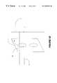
- FIG. 1 AA first embodiment 1 of the subject invention is illustrated in FIG. 1 A.
- the first embodimentcomprises an electrical appliance 7 configured with an antenna 6 .
- antenna 6is a radiator configured for the ISM spectrum.
- the antennais configured to handle RF or microwave frequencies including those outside the ISM spectrum.
- the antennahas a form factor configured to achieve coverage in the ISM spectrum of a typical room, e.g., 15 ⁇ 15 ft. 2 , in a home or office.
- the gain of the antennais such that, as part of a typical transceiver, the radiated power from the antenna is between about 0.1 to about 10 milliwatts (mW), and advantageeously about 1 mW.
- the antennais a generally isotropic antenna or has a generally spherical radiation pattern.
- A/C power lines 3provide power to the electrical appliance.
- the electrical applianceis a light fixture or the like which is hard-wired into a home or office, and A/C power lines 3 are part of the power distribution system pre-wired within the home or office.
- the electrical applianceis a plug-in device such as a desk lamp or the like, and the A/C power lines 3 are the A/C power cord of the electrical appliance which is plugged into wall socket or outlet 4 .
- a user device 5is coupled to the electrical appliance 7 through the A/C power lines 9 of the device 5 in combination with the A/C power lines 3 of the electrical appliance.
- the A/C power lines 3 and 9are coupled together by means of a wall socket 4 which interfaces between the two.
- A/C power lines 3 of the appliance 7are pre-wired power distribution lines within a home or office.
- the wall socket 4is provided for allowing other devices or appliances to plug into the power distribution system.
- the power distribution lines 3are accessible through an outlet 4 a .
- the A/C power lines 9 for the user device 5plug into the outlet through plug 9 a , thus achieving coupling between the lines 9 and the lines 3 .
- the appliance 7is a plug-in appliance, and the A/C power cord 3 for the device is plugged into outlet 4 b of wall socket 4 through plug 3 a .
- User device 5is also a plug-in device, and the A/C power cord 9 for this device is plugged into outlet 4 a of wall socket 4 through plug 9 a .
- Both outlets 4 a and 4 bare coupled to and provide access to the pre-wired power distribution system 4 c for the home or office.
- A/C power lines 3 and 9are coupled together by virtue of user device 5 and electrical appliance 9 being plugged into the wall socket 4 .
- user device 5is hard-wired into the power distribution system of the home or office, and electrical appliance 7 is a plug-in device.
- the A/C power lines 9 for the user device 5are part of the pre-wired power distribution system of the home or office, and the A/C power cord 3 for the appliance is coupled to the power distribution system, and to A/C power lines 9 , through outlet 4 a of wall socket 4 .
- both user device 5 and electrical appliance 9are hard-wired into the power distribution system 4 c for the home or office.
- the A/C power lines 3 and 9are coupled together by means other than a wall socket or outlet.
- the user device 5includes a user interface for interacting with a user, and allowing the user to input commands and/or information 8 over the user interface. Responsive to these commands/information 8 , user commands and/or information, the latter in the form of either voice or data, is communicated with antenna 6 .
- user device 5includes a transceiver for modulating user information onto a signal at the carrier frequency, and placing the modulated signal onto the A/C power lines 9 of the device, whereby the modulated signal is superimposed onto the 50-60 Hz power signal which is used to power the device 5 and appliance 7 , and transmitted to the antenna 6 over A/C power lines 9 and 3 . At that point, the signal is transmitted out over a wireless interface to another device or appliance through antenna 6 .
- the modulated signalis transmitted to user device 5 over the A/C power lines 3 and 9 .
- the transceiver in the device 5is configured with suitable means to separate the modulated signal from the power signal used to power the device 5 and appliance 9 , to isolate the separated signal from the power signal, and to demodulate the signal to baseband frequencies.
- This transceivermay also be configured with means to bandlimit the modulated signal, and to amplify it.
- the information in the baseband signalmay then be communicated to the user through the user interface.
- the means for separating the modulated signal from the power signalincludes a band pass filter which has a corner frequency between the carrier frequency of the modulated signal and the relatively low (50-60 Hz) frequency of the power signal. Additional detail about transmitting information over the power distribution system of a home or office is available at www.interlogis.com, which is hereby fully incorporated by reference herein as though set forth in full.
- the transceiver and antenna 6are suitably configured such that the carrier frequency of the signal transmitted and received over the wireless interface is within the ISM spectrum. In another implementation, the transceiver and antenna 6 are suitably configured such that the carrier frequency of the signal transmitted and received over the wireless interface is an RF or microwave frequency which may be outside the ISM spectrum. In a third implementation, the carrier frequencies for transmission and reception over the wireless interface are different. In one example of this implementation, the carrier frequency for the transmit signal is within the ISM spectrum, but that for the receive signal is outside the ISM spectrum. In another example, the reverse is the case. In a fourth implementation, both carrier frequencies are within the ISM spectrum but spaced to allow full duplex communication.
- FIG. 1BAn implementation 10 of the first embodiment of the subject invention is illustrated in FIG. 1B in which, compared to FIG. 1A, like elements are referenced with like identifying numerals.
- the antenna 6is integrated within a light bulb 11 .
- the light bulb 11includes a threaded terminal 11 a for screwing into an electrical outlet (not shown) for the appliance, thus coupling the power distribution system 3 a for the light bulb to the A/C power lines or cord 3 for the appliance.
- the antenna 6is coupled to the power distribution system 3 a in parallel with a filament 12 of the light bulb.
- the power distribution system 3 aprovides power to the filament 12 , which radiates illumination responsive thereto.
- power distribution system 3 ain combination with lines 3 and 9 , may communicate a signal received by antenna 6 over the wireless interface to user device 5 , and may also communicate a modulated signal provided by user device 5 to antenna 6 for transmission over the wireless interface.
- FIG. 1Cillustrates a second implementation 20 of the first embodiment of the subject invention in which, relative to FIG. 1B, like elements are referenced with like identifying numerals.
- antenna 6is retrofitted to an existing light bulb 11 .
- the implementation of FIG. 1Bmay require remanufacturing of the light bulb to allow incorporation therein of the antenna 6 .
- the antenna 6is retrofitted to the end of threaded terminal 11 a , but it should be appreciated in practice that other implementations are possible.
- the antenna 6is encapsulated within an adapter which is situated between an ordinary light bulb and the A/C socket for the bulb. The adapter functions as both an antenna and an A/C bypass.
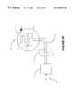
- FIG. 2Aillustrates a second embodiment 40 of the subject invention in which, compared to FIG. 1A, like elements are referenced with like identifying numerals.
- a module 41is integrated with the antenna 6 to form a transceiver within electrical appliance 7 .
- the transceiveris coupled to A/C power lines 3 a.
- a signalis received over the wireless interface by antenna 6 , and provided to module 41 .
- the signalis demodulated to baseband frequencies.
- the signalmay be bandlimited to the desired frequency range, amplified, and/or low-pass filtered.
- the baseband signalis then provided over A/C power lines 3 a , 3 , and 9 to user device 5 .
- a baseband signalcomprising user information and/or commands, whether in the form of voice or data, is transmitted from user device 5 over A/C power lines 9 , 3 and 3 a to module 41 .
- the baseband signalis modulated onto a carrier signal at the desired carrier frequency.
- the signalmay be bandlimited to the desired range of frequencies, and amplified.
- the modulated signalis then transmitted over the wireless interface by antenna 6 .
- the frequency of transmission and frequency of receptionare different to allow for full-duplex transmission.
- bothare within the ISM spectrum, but are spaced by a certain distance.
- bothare within the RF or microwave spectrum exclusive or inclusive of the ISM spectrum.
- oneis within the ISM spectrum, and the other is within the RF or microwave spectrum inclusive or exclusive of the ISM spectrum.
- the frequencies of transmission and receptionare about the same, and only half-duplex transmission is supported.
- FIG. 2BOne implementation 50 of the second embodiment is illustrated in FIG. 2B in which, compared to previous figures, like elements are referenced with like identifying numerals.
- electrical appliance 7is a light bulb 11 .
- the transceiver formed of antenna 6 and module 41is coupled to the A/C power lines 3 a in parallel with filament 12 .
- FIG. 2CAnother implementation 160 of the second embodiment is illustrated in FIG. 2C in which, compared to previous figures, like elements are referenced with like identifying numerals.
- electrical appliance 7is again a light bulb 11 in which the transceiver formed of antenna 6 and module 41 is placed at the end of the threaded terminal 11 a of the light bulb.
- the transceiverfunctions as described before, but in addition, it acts as a bypass for the A/C power lines 3 a , which, as shown, extend through the transceiver and couple to the antenna 6 .
- electrical appliance 7includes a module 42 which forms a repeater in combination with antenna 6 .
- the repeaterreceives over the wireless interface a signal, amplifies the signal, and then retransmits it over the wireless interface, optionally at a different carrier frequency than the received frequency. Note that the repeater need not be coupled to the A/C power lines 3 for appliance 7 in this embodiment.
- the frequency of reception and the frequency of transmissionmay both be within the ISM spectrum, or both may be within the RF or microwave spectrum, exclusive or inclusive of the ISM spectrum.
- the frequency of receptionmay the same as or different from the frequency of transmission.
- FIG. 2Eillustrates an implementation 180 of the embodiment of FIG. 2D in which electrical appliance 7 is a light bulb 11 .
- electrical appliance 7is a light bulb 11 .
- a repeaterformed from the combination of antenna 6 and module 42 .
- a filament 12coupled to the A/C power distribution system 3 a of the light bulb. Note in this implementation that the repeater need not be coupled to the A/C power distribution system of the light bulb 11 .
- FIG. 2Fillustrates a fourth embodiment 190 of the subject invention in which a module 43 is included within electrical appliance 7 .
- the module 43combines the functionality of module 41 of the embodiment of FIG. 2A, and module 42 in the embodiment of FIG. 2 D.
- the module 43forms a transceiver in combination with antenna 6 , which functions as previously described.
- the module 43forms a repeater in combination with antenna 6 , which functions as previously described.
- any of the foregoing embodimentsare configured as nodes in a wireless communications system, and any of the nodes in the wireless communications system can communicate with any other node in the system over the wireless interface.
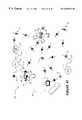
- FIG. 3 AAn implementation 140 of such a system is illustrated in FIG. 3 A.
- the system in this implementationcomprises three nodes.
- the first nodecomprises desktop computer 141 which is interfaced to desk lamp 142 through A/C power lines 143 .
- the lamp 142includes a light bulb (not independently shown) configured with an antenna and optionally a transceiver in accordance with the foregoing embodiments.
- User information and/or commands originating from the computer 141are transmitted to the antenna in the lamp 142 through the power distribution lines, and then out over the wireless interface to one of the other nodes.
- information and/or commands originating from one of the other nodesare received from the antenna in lamp 142 , and transmitted to the computer 141 through A/C power transmission lines 143 .
- the modulation and demodulation functionsmay be performed within computer 141 , or may be performed by a transceiver included in the light bulb of lamp 142 .
- a second such nodeis formed from light fixture 144 which is interfaced to laptop 145 over A/C power lines 146 .
- the light bulb (not independently shown) in the light fixture 144includes an antenna and optionally a transceiver in accordance with any of the foregoing embodiments.
- user commands and/or informationis communicated back and forth between laptop 145 and the light bulb in the light fixture 144 by means of A/C power lines 146 .
- These commands and/or informationmay are also be communicated to one of the other nodes through the wireless interface.
- a third nodeis formed of wireless handset 147 which, as is known, includes an antenna and transceiver configured to operate at the desired frequency of operation.
- the system of FIG. 3Ais managed through a token ring protocol in which only the node which is the current holder of the token has the right to transmit.
- the systemforms an IEEE 802.11 compliant wireless LAN as described in www.breezecom.com, which is fully incorporated by reference herein as through set forth in full.
- the networkis divided into cells, with a base station handling communication between any two nodes within a cell. Communications is performed using a frequency hopping protocol at frequencies of about 2.4 GHz.
- a carrier sense/multiple access/collision avoidance protocolis employed in which a node, prior to transmitting, senses whether the carrier is busy or not. If so, the node employs an exponentially distributed random backoff procedure to wait a random amount of time before attempting to transmit again. If not, the node transmits.
- FIG. 3BA second implementation 150 of such a system is illustrated in FIG. 3B in which, compared to FIG. 3A, like elements are referenced with like identifying numerals.
- the first nodehas been replaced with a light fixture 151 including a light bulb (not independently shown) configured to act as a repeater in accordance with the foregoing embodiments.
- a light fixture 151including a light bulb (not independently shown) configured to act as a repeater in accordance with the foregoing embodiments.
- transmissions between the other two nodesoccur by way of the repeater.
- a first nodecomprises desktop computer 62 in combination with desk lamp 63 which is coupled to the computer 62 through A/C power lines 64 .
- a light bulb (not independently shown) in the lamp 83includes an antenna and optionally a transceiver configured in accordance with the subject invention.
- Information and/or commands originating in computer 62may be provided to the light bulb (not independently shown) in lamp 63 over the A/C power lines 64 for transmission to another node over a wireless interface, and information and/or commands from another node may be received by the light bulb, and then provided to the computer 62 over A/C power lines 64 .
- a second nodeis formed of a landline telephone 69 which is interfaced to the Public Switched Telephone Network (PSTN) 70 through landlines 71 .
- PSTNPublic Switched Telephone Network
- the second nodeis assumed to be at about the same location as the first node, i.e., on or about desk 61 .
- a third nodeis formed of landline phone 75 which is similarly interfaces to the PSTN 70 . This phone is assumed to be remote from the first node.
- a fourth nodeis formed of cellular handset 74 which is interfaced to a wireless infrastructure system 73 through a wireless interface.
- the wireless infrastructure system 73may include one or more base station transceiver subsystems (BTS), one or more base station controllers (BSC), and one or more mobile switching systems (MTS).
- BTSbase station transceiver subsystem
- BSCbase station controller
- MTSmobile switching systems
- the wireless infrastructure system 73is in turn interfaced to the PSTN 70 over landlines 72 .
- a fifth nodecomprises light fixture 77 which includes a light bulb (not independently shown) configured to function as a repeater in accordance with the subject invention.
- a sixth nodecomprises desktop computer 62 in combination with television set 81 .
- Television set 81includes an antenna and optionally a transceiver configured in accordance with the subject invention.
- the television set 80may be controlled by a remote control device 80 which is part of the sixth node.
- Information and/or commands originating in the computer 62may be provided to the antenna and/or transceiver in television set 81 over A/C power lines 82 for transmission to another node, and information and/or commands from another node may be received by the antenna and/or transceiver in the television set 81 , and then provided to the computer 62 over the A/C power lines 82 .
- information and/or commands from remote control device 80may be provided to the television set over a wireless interface. This information and/or commands may be for the purpose of controlling the television set 81 or for transmission to another node.
- a seventh nodecomprises cordless handset 76 in combination with cordless base station 78 .
- the handset 76is configured to communicate with base station 78 over a wireless interface.
- the base station 78in turn is interfaced to PSTN 70 through landlines 79 .
- An eighth nodecomprises laptop 66 in combination with table lamp 67 which is interfaced to the laptop 66 through A/C power lines 68 .
- a light bulb (not independently shown) in lamp 67includes an antenna and optionally a transceiver configured in accordance with the subject invention.
- Information and/or commands originating from the laptopmay be provided to the light bulb through A/C power lines 68 for transmission over a wireless interface to another node, and information and/or commands originating from another node may be received by the light bulb and provided to the laptop over the A/C power lines 68 .
- the first, second, fifth, sixth, seventh, and eighth nodesare all assumed to be physically within the same home or office building, although they may be in different rooms of the same.
- the third and fourth nodesare assumed to be externally located.
- the computer 62 in the first and sixth nodesis configured to communicate with the laptop 66 in the eighth node over a wireless interface comprising the antennas and/or transceivers in the light bulbs in lamps 63 and 67 .
- computer 62is configured to communicate with the laptop 66 in the eighth node over a wireless interface comprising the antennas and/or transceivers in the television set 81 and the light bulb in the lamp 67 .
- transmissions between the television set 81 and the laptop 66occur by means of the repeater within light fixture 77 .
- Voice communicationmay be exchanged between either of telephones 69 and 75 and handset 74 through the PSTN and the wireless interface existing between the infrastructure system 73 and the handset 74 .
- Voice trafficmay also be exchanged between handset 74 and the laptop 66 through a wireless interface comprising the antenna and transceiver in handset 74 and the antenna and/or transceiver in the light bulb of lamp 67 .
- Voice communicationmay also be exchanged between cordless handset 76 and either of phones 69 or 75 through the wireless interface existing between the handset 76 and the base station 78 , and the PSTN.
- voice traffic from the handset 76may be transmitted to either of these phones through a wireless interface comprising repeater 77 and infrastructure system 73 in combination with the PSTN. This link allows communications with the handset 76 to occur even if the handset 76 is out of range of the base station 78 .
- Voice trafficmay also be exchanged between laptop 66 (which may be equipped with a microphone and speakers) and handset 76 through a wireless link comprising the antenna and transceiver in handset 76 , repeater 77 , and the antenna and/or transceiver in the light bulb in the lamp 67 .
- Commands originating from remote control device 80may also be provided to other nodes through repeater 77 .
- step 91a signal is received over a wireless interface.
- the signalhas a carrier frequency within the ISM spectrum.
- the carrier frequencyis within the RF or microwave spectrum, either inclusive or exclusive of the ISM spectrum.
- a repeating functionis performed in which the signal is retransmitted, optionally after being amplified and optionally after adjusting the carrier frequency of the signal.
- the carrier frequency of the received signalis within the RF or microwave spectrum, exclusive of the ISM spectrum, and the carrier frequency of the retransmitted signal has been adjusted to be within the ISM spectrum.
- the carrier frequency of the retransmitted signalis unchanged in relation to that of the received signal.
- the carrier frequency of the retransmitted signalhas been adjusted in relation to that of the received signal.
- the carrier frequency of the received signalis within the ISM spectrum, and the carrier frequency of the retransmitted signal has been adjusted to be within the RF spectrum exclusive of the ISM spectrum.
- FIG. 4Billustrates a second method of operation 100 of an electrical appliance in accordance with the subject invention.
- a first signalis received over a wireless interface from a signal source which may be a node in a system, a wireless or personal communication device, a mobile or subscriber device, a cellular handset, a cordless handset or base station, a processor, a laptop, a desktop computer, etc.
- the carrier frequency of the signalmay be within the ISM spectrum, or it may be within the RF or microwave spectrum, inclusive or exclusive of the ISM spectrum.
- a second signal derived from the first signalis provided to a user over the A/C power lines or A/C power distribution system of the device.
- the second signalis the first signal.
- the second signalis different from the first signal.
- FIG. 4Cillustrates a third method of operation 110 of an electrical appliance in accordance with the subject invention.
- a first signalis providedover the A/C power transmission lines or A/C power distribution system of an electrical appliance.
- the carrier frequency of the signalmay be within the ISM spectrum, or it may be within the RF or microwave spectrum, inclusive or exclusive of the ISM spectrum.
- a second signal derived from the first signalis transmitted over a wireless interface to a signal destination which may be a node in a system, a wireless or personal communication device, a mobile or subscriber device, a cellular handset, a cordless handset or base station, a processor, a laptop, a desktop computer, etc.
- the second signalis the first signal; in a second implementation, the second signal is different from the first signal.
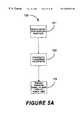
- FIG. 5Aillustrates a fourth method of operation 120 of an electrical appliance configured in accordance with the subject invention.
- a signalis received over a wireless interface with a signal source.
- the carrier frequency of the signalmay be within the ISM spectrum, or the RF or microwave spectrum, inclusive or exclusive of the ISM spectrum.
- step 122the signal is demodulated to baseband frequencies.
- additional stepsmay also be performed, including bandlimiting, amplifying, or low-pass filtering steps.
- step 123the baseband signal is transmitted to a user over the A/C power lines or A/C power distribution system of the electrical appliance.
- FIG. 5Billustrates a fifth method of operation of an electrical appliance configured in accordance with the subject invention.
- a signal at baseband frequenciesis received from a user.
- the signalis transmitted over the A/C power distribution lines or power distribution system of the electrical appliance to a modulator located within the electrical appliance.
- a carrier signal at a desired transmit frequencyis modulated with the baseband signal.
- the carrier frequencymay be within the ISM spectrum, or it may be within the RF or microwave spectrum, inclusive or exclusive of the ISM spectrum.
- additional processingis performed on the signal, including bandlimiting, amplifying, or filtering steps.
- the modulated signalis transmitted over the wireless interface.
Landscapes
- Engineering & Computer Science (AREA)
- Power Engineering (AREA)
- Computer Networks & Wireless Communication (AREA)
- Signal Processing (AREA)
- Radio Relay Systems (AREA)
Abstract
Description
Claims (21)
Priority Applications (1)
| Application Number | Priority Date | Filing Date | Title |
|---|---|---|---|
| US09/409,297US6653932B1 (en) | 1999-09-29 | 1999-09-29 | System and method for achieving wireless communications coverage in a local area |
Applications Claiming Priority (1)
| Application Number | Priority Date | Filing Date | Title |
|---|---|---|---|
| US09/409,297US6653932B1 (en) | 1999-09-29 | 1999-09-29 | System and method for achieving wireless communications coverage in a local area |
Publications (1)
| Publication Number | Publication Date |
|---|---|
| US6653932B1true US6653932B1 (en) | 2003-11-25 |
Family
ID=29584664
Family Applications (1)
| Application Number | Title | Priority Date | Filing Date |
|---|---|---|---|
| US09/409,297Expired - LifetimeUS6653932B1 (en) | 1999-09-29 | 1999-09-29 | System and method for achieving wireless communications coverage in a local area |
Country Status (1)
| Country | Link |
|---|---|
| US (1) | US6653932B1 (en) |
Cited By (35)
| Publication number | Priority date | Publication date | Assignee | Title |
|---|---|---|---|---|
| US20030043972A1 (en)* | 2001-08-29 | 2003-03-06 | Burnham Robert J. | Wireless entertainment system for a vehicle |
| US20030185289A1 (en)* | 2001-12-07 | 2003-10-02 | Koninklijke Philips Electronics N.V. | Cordless modem for portable computers |
| US20050141757A1 (en)* | 2001-10-12 | 2005-06-30 | Inria Institut National De Recherche En Informatique Et En Automatique | Image processing device and method for detecting developing lesions |
| US7006523B2 (en) | 1998-07-28 | 2006-02-28 | Serconet Ltd. | Local area network of serial intelligent cells |
| WO2005099346A3 (en)* | 2004-04-15 | 2006-03-09 | Koninkl Philips Electronics Nv | Use of lamp electrodes as antenna |
| US20060152344A1 (en)* | 2002-12-07 | 2006-07-13 | Mowery Richard A Jr | Powerline Communication Network Handoff |
| US7197028B2 (en) | 2000-04-18 | 2007-03-27 | Serconet Ltd. | Telephone communication system over a single telephone line |
| US20070178912A1 (en)* | 2000-03-14 | 2007-08-02 | Robert Baranowski | System and method for enhancing user experience in a wide-area facility having a distributed, bounded environment |
| US20070206629A1 (en)* | 2006-03-03 | 2007-09-06 | Lite-On Technology Corp. | Network Equipment Applied In Power Line Carrier Communication System |
| US20070259644A1 (en)* | 2006-03-21 | 2007-11-08 | Asoka Usa Corporation | Method and system for powerline local area networks over coaxial cable |
| US7317793B2 (en) | 2003-01-30 | 2008-01-08 | Serconet Ltd | Method and system for providing DC power on local telephone lines |
| US7453895B2 (en) | 2001-10-11 | 2008-11-18 | Serconet Ltd | Outlet with analog signal adapter, a method for use thereof and a network using said outlet |
| US20090016224A1 (en)* | 2007-06-04 | 2009-01-15 | Swades De | Multi-criteria optimization for relaying in multi-hop wireless ad hoc and sensor networks |
| US7483524B2 (en) | 1999-07-20 | 2009-01-27 | Serconet, Ltd | Network for telephony and data communication |
| US7486648B1 (en)* | 1999-10-11 | 2009-02-03 | Park Tours, Inc. | Wireless extension of local area networks |
| US7522615B2 (en) | 2002-11-13 | 2009-04-21 | Serconet, Ltd. | Addressable outlet, and a network using same |
| US7522714B2 (en) | 2000-03-20 | 2009-04-21 | Serconet Ltd. | Telephone outlet for implementing a local area network over telephone lines and a local area network using such outlets |
| EP2061224A1 (en) | 2004-05-06 | 2009-05-20 | Serconet Ltd. | Module for transmission and reception of a wireless based signal over wiring |
| US7633966B2 (en) | 2000-04-19 | 2009-12-15 | Mosaid Technologies Incorporated | Network combining wired and non-wired segments |
| US7680255B2 (en) | 2001-07-05 | 2010-03-16 | Mosaid Technologies Incorporated | Telephone outlet with packet telephony adaptor, and a network using same |
| US7688841B2 (en) | 2003-07-09 | 2010-03-30 | Mosaid Technologies Incorporated | Modular outlet |
| US7756268B2 (en) | 2004-02-16 | 2010-07-13 | Mosaid Technologies Incorporated | Outlet add-on module |
| US7813451B2 (en) | 2006-01-11 | 2010-10-12 | Mobileaccess Networks Ltd. | Apparatus and method for frequency shifting of a wireless signal and systems using frequency shifting |
| US7853238B1 (en) | 2007-03-22 | 2010-12-14 | Nextel Communications Inc. | Powerline base station |
| US7873058B2 (en) | 2004-11-08 | 2011-01-18 | Mosaid Technologies Incorporated | Outlet with analog signal adapter, a method for use thereof and a network using said outlet |
| US7929940B1 (en) | 2006-04-18 | 2011-04-19 | Nextel Communications Inc. | System and method for transmitting wireless digital service signals via power transmission lines |
| CN102081450A (en)* | 2009-11-27 | 2011-06-01 | 索尼公司 | Electric power supply device, electric power supply method and electric power supply system |
| US8175649B2 (en) | 2008-06-20 | 2012-05-08 | Corning Mobileaccess Ltd | Method and system for real time control of an active antenna over a distributed antenna system |
| US8582598B2 (en) | 1999-07-07 | 2013-11-12 | Mosaid Technologies Incorporated | Local area network for distributing data communication, sensing and control signals |
| US8594133B2 (en) | 2007-10-22 | 2013-11-26 | Corning Mobileaccess Ltd. | Communication system using low bandwidth wires |
| US8897215B2 (en) | 2009-02-08 | 2014-11-25 | Corning Optical Communications Wireless Ltd | Communication system using cables carrying ethernet signals |
| US8941976B1 (en) | 2011-01-25 | 2015-01-27 | Western Digital Technologies, Inc. | Configurable powerline Ethernet adapter and power supply |
| US9184960B1 (en) | 2014-09-25 | 2015-11-10 | Corning Optical Communications Wireless Ltd | Frequency shifting a communications signal(s) in a multi-frequency distributed antenna system (DAS) to avoid or reduce frequency interference |
| US9338823B2 (en) | 2012-03-23 | 2016-05-10 | Corning Optical Communications Wireless Ltd | Radio-frequency integrated circuit (RFIC) chip(s) for providing distributed antenna system functionalities, and related components, systems, and methods |
| US10986165B2 (en) | 2004-01-13 | 2021-04-20 | May Patents Ltd. | Information device |
Citations (8)
| Publication number | Priority date | Publication date | Assignee | Title |
|---|---|---|---|---|
| US4980665A (en)* | 1987-05-22 | 1990-12-25 | Recoton Corporation | Remote control repeater |
| US5481249A (en)* | 1992-02-14 | 1996-01-02 | Canon Kabushiki Kaisha | Bidirectional communication apparatus for transmitting/receiving information by wireless communication or through a power line |
| US5565855A (en)* | 1991-05-06 | 1996-10-15 | U.S. Philips Corporation | Building management system |
| US5905442A (en)* | 1996-02-07 | 1999-05-18 | Lutron Electronics Co., Inc. | Method and apparatus for controlling and determining the status of electrical devices from remote locations |
| US6151480A (en)* | 1997-06-27 | 2000-11-21 | Adc Telecommunications, Inc. | System and method for distributing RF signals over power lines within a substantially closed environment |
| US6175860B1 (en)* | 1997-11-26 | 2001-01-16 | International Business Machines Corporation | Method and apparatus for an automatic multi-rate wireless/wired computer network |
| US6229433B1 (en)* | 1999-07-30 | 2001-05-08 | X-10 Ltd. | Appliance control |
| US6492897B1 (en)* | 2000-08-04 | 2002-12-10 | Richard A. Mowery, Jr. | System for coupling wireless signals to and from a power transmission line communication system |
- 1999
- 1999-09-29USUS09/409,297patent/US6653932B1/ennot_activeExpired - Lifetime
Patent Citations (8)
| Publication number | Priority date | Publication date | Assignee | Title |
|---|---|---|---|---|
| US4980665A (en)* | 1987-05-22 | 1990-12-25 | Recoton Corporation | Remote control repeater |
| US5565855A (en)* | 1991-05-06 | 1996-10-15 | U.S. Philips Corporation | Building management system |
| US5481249A (en)* | 1992-02-14 | 1996-01-02 | Canon Kabushiki Kaisha | Bidirectional communication apparatus for transmitting/receiving information by wireless communication or through a power line |
| US5905442A (en)* | 1996-02-07 | 1999-05-18 | Lutron Electronics Co., Inc. | Method and apparatus for controlling and determining the status of electrical devices from remote locations |
| US6151480A (en)* | 1997-06-27 | 2000-11-21 | Adc Telecommunications, Inc. | System and method for distributing RF signals over power lines within a substantially closed environment |
| US6175860B1 (en)* | 1997-11-26 | 2001-01-16 | International Business Machines Corporation | Method and apparatus for an automatic multi-rate wireless/wired computer network |
| US6229433B1 (en)* | 1999-07-30 | 2001-05-08 | X-10 Ltd. | Appliance control |
| US6492897B1 (en)* | 2000-08-04 | 2002-12-10 | Richard A. Mowery, Jr. | System for coupling wireless signals to and from a power transmission line communication system |
Non-Patent Citations (3)
| Title |
|---|
| Intelogis PLUG-IN(TM)Technology Power Line Communications, White Paper, found at the following web location: http://www.Intelogis.com (11/98). |
| Intelogis PLUG-IN™Technology Power Line Communications, White Paper, found at the following web location: http://www.Intelogis.com (11/98). |
| News Release, "Intelogis announces high-speed data transmission breakthrough in powerline networking technology," fournd at the following web location: http://www.intelogis.com/news/021099.com (Sep. 14, 1999). |
Cited By (120)
| Publication number | Priority date | Publication date | Assignee | Title |
|---|---|---|---|---|
| US8885659B2 (en) | 1998-07-28 | 2014-11-11 | Conversant Intellectual Property Management Incorporated | Local area network of serial intelligent cells |
| US7424031B2 (en) | 1998-07-28 | 2008-09-09 | Serconet, Ltd. | Local area network of serial intelligent cells |
| US8867523B2 (en) | 1998-07-28 | 2014-10-21 | Conversant Intellectual Property Management Incorporated | Local area network of serial intelligent cells |
| US7006523B2 (en) | 1998-07-28 | 2006-02-28 | Serconet Ltd. | Local area network of serial intelligent cells |
| US8325636B2 (en) | 1998-07-28 | 2012-12-04 | Mosaid Technologies Incorporated | Local area network of serial intelligent cells |
| US7016368B2 (en) | 1998-07-28 | 2006-03-21 | Serconet, Ltd. | Local area network of serial intelligent cells |
| US7035280B2 (en) | 1998-07-28 | 2006-04-25 | Serconet Ltd. | Local area network of serial intelligent cells |
| US8270430B2 (en) | 1998-07-28 | 2012-09-18 | Mosaid Technologies Incorporated | Local area network of serial intelligent cells |
| US7095756B2 (en) | 1998-07-28 | 2006-08-22 | Serconet, Ltd. | Local area network of serial intelligent cells |
| US7187695B2 (en) | 1998-07-28 | 2007-03-06 | Serconet Ltd. | Local area network of serial intelligent cells |
| US8885660B2 (en) | 1998-07-28 | 2014-11-11 | Conversant Intellectual Property Management Incorporated | Local area network of serial intelligent cells |
| US7292600B2 (en) | 1998-07-28 | 2007-11-06 | Serconet Ltd. | Local area network of serial intellegent cells |
| US7986708B2 (en) | 1998-07-28 | 2011-07-26 | Mosaid Technologies Incorporated | Local area network of serial intelligent cells |
| US7653015B2 (en) | 1998-07-28 | 2010-01-26 | Mosaid Technologies Incorporated | Local area network of serial intelligent cells |
| US7221679B2 (en) | 1998-07-28 | 2007-05-22 | Serconet Ltd. | Local area network of serial intelligent cells |
| US7978726B2 (en) | 1998-07-28 | 2011-07-12 | Mosaid Technologies Incorporated | Local area network of serial intelligent cells |
| US7969917B2 (en) | 1998-07-28 | 2011-06-28 | Mosaid Technologies Incorporated | Local area network of serial intelligent cells |
| US7965735B2 (en) | 1998-07-28 | 2011-06-21 | Mosaid Technologies Incorporated | Local area network of serial intelligent cells |
| US8908673B2 (en) | 1998-07-28 | 2014-12-09 | Conversant Intellectual Property Management Incorporated | Local area network of serial intelligent cells |
| US7830858B2 (en) | 1998-07-28 | 2010-11-09 | Mosaid Technologies Incorporated | Local area network of serial intelligent cells |
| US7852874B2 (en) | 1998-07-28 | 2010-12-14 | Mosaid Technologies Incorporated | Local area network of serial intelligent cells |
| US8582598B2 (en) | 1999-07-07 | 2013-11-12 | Mosaid Technologies Incorporated | Local area network for distributing data communication, sensing and control signals |
| US8929523B2 (en) | 1999-07-20 | 2015-01-06 | Conversant Intellectual Property Management Inc. | Network for telephony and data communication |
| US7522713B2 (en) | 1999-07-20 | 2009-04-21 | Serconet, Ltd. | Network for telephony and data communication |
| US7483524B2 (en) | 1999-07-20 | 2009-01-27 | Serconet, Ltd | Network for telephony and data communication |
| US8351582B2 (en) | 1999-07-20 | 2013-01-08 | Mosaid Technologies Incorporated | Network for telephony and data communication |
| US7492875B2 (en) | 1999-07-20 | 2009-02-17 | Serconet, Ltd. | Network for telephony and data communication |
| US7486648B1 (en)* | 1999-10-11 | 2009-02-03 | Park Tours, Inc. | Wireless extension of local area networks |
| US20070178912A1 (en)* | 2000-03-14 | 2007-08-02 | Robert Baranowski | System and method for enhancing user experience in a wide-area facility having a distributed, bounded environment |
| US8855277B2 (en) | 2000-03-20 | 2014-10-07 | Conversant Intellectual Property Managment Incorporated | Telephone outlet for implementing a local area network over telephone lines and a local area network using such outlets |
| US7522714B2 (en) | 2000-03-20 | 2009-04-21 | Serconet Ltd. | Telephone outlet for implementing a local area network over telephone lines and a local area network using such outlets |
| US7715534B2 (en) | 2000-03-20 | 2010-05-11 | Mosaid Technologies Incorporated | Telephone outlet for implementing a local area network over telephone lines and a local area network using such outlets |
| US8363797B2 (en) | 2000-03-20 | 2013-01-29 | Mosaid Technologies Incorporated | Telephone outlet for implementing a local area network over telephone lines and a local area network using such outlets |
| US8559422B2 (en) | 2000-04-18 | 2013-10-15 | Mosaid Technologies Incorporated | Telephone communication system over a single telephone line |
| US7593394B2 (en) | 2000-04-18 | 2009-09-22 | Mosaid Technologies Incorporated | Telephone communication system over a single telephone line |
| US8223800B2 (en) | 2000-04-18 | 2012-07-17 | Mosaid Technologies Incorporated | Telephone communication system over a single telephone line |
| US7197028B2 (en) | 2000-04-18 | 2007-03-27 | Serconet Ltd. | Telephone communication system over a single telephone line |
| US7466722B2 (en) | 2000-04-18 | 2008-12-16 | Serconet Ltd | Telephone communication system over a single telephone line |
| US7397791B2 (en) | 2000-04-18 | 2008-07-08 | Serconet, Ltd. | Telephone communication system over a single telephone line |
| US8000349B2 (en) | 2000-04-18 | 2011-08-16 | Mosaid Technologies Incorporated | Telephone communication system over a single telephone line |
| US8982904B2 (en) | 2000-04-19 | 2015-03-17 | Conversant Intellectual Property Management Inc. | Network combining wired and non-wired segments |
| US7715441B2 (en) | 2000-04-19 | 2010-05-11 | Mosaid Technologies Incorporated | Network combining wired and non-wired segments |
| US8873575B2 (en) | 2000-04-19 | 2014-10-28 | Conversant Intellectual Property Management Incorporated | Network combining wired and non-wired segments |
| US8873586B2 (en) | 2000-04-19 | 2014-10-28 | Conversant Intellectual Property Management Incorporated | Network combining wired and non-wired segments |
| US8848725B2 (en) | 2000-04-19 | 2014-09-30 | Conversant Intellectual Property Management Incorporated | Network combining wired and non-wired segments |
| US7876767B2 (en)* | 2000-04-19 | 2011-01-25 | Mosaid Technologies Incorporated | Network combining wired and non-wired segments |
| US7636373B2 (en) | 2000-04-19 | 2009-12-22 | Mosaid Technologies Incorporated | Network combining wired and non-wired segments |
| US8982903B2 (en) | 2000-04-19 | 2015-03-17 | Conversant Intellectual Property Management Inc. | Network combining wired and non-wired segments |
| US7933297B2 (en) | 2000-04-19 | 2011-04-26 | Mosaid Technologies Incorporated | Network combining wired and non-wired segments |
| US8289991B2 (en) | 2000-04-19 | 2012-10-16 | Mosaid Technologies Incorporated | Network combining wired and non-wired segments |
| US8867506B2 (en) | 2000-04-19 | 2014-10-21 | Conversant Intellectual Property Management Incorporated | Network combining wired and non-wired segments |
| US7633966B2 (en) | 2000-04-19 | 2009-12-15 | Mosaid Technologies Incorporated | Network combining wired and non-wired segments |
| US7680255B2 (en) | 2001-07-05 | 2010-03-16 | Mosaid Technologies Incorporated | Telephone outlet with packet telephony adaptor, and a network using same |
| US20030043972A1 (en)* | 2001-08-29 | 2003-03-06 | Burnham Robert J. | Wireless entertainment system for a vehicle |
| US7889720B2 (en) | 2001-10-11 | 2011-02-15 | Mosaid Technologies Incorporated | Outlet with analog signal adapter, a method for use thereof and a network using said outlet |
| US7860084B2 (en) | 2001-10-11 | 2010-12-28 | Mosaid Technologies Incorporated | Outlet with analog signal adapter, a method for use thereof and a network using said outlet |
| US7453895B2 (en) | 2001-10-11 | 2008-11-18 | Serconet Ltd | Outlet with analog signal adapter, a method for use thereof and a network using said outlet |
| US7953071B2 (en) | 2001-10-11 | 2011-05-31 | Mosaid Technologies Incorporated | Outlet with analog signal adapter, a method for use thereof and a network using said outlet |
| US20050141757A1 (en)* | 2001-10-12 | 2005-06-30 | Inria Institut National De Recherche En Informatique Et En Automatique | Image processing device and method for detecting developing lesions |
| US20030185289A1 (en)* | 2001-12-07 | 2003-10-02 | Koninklijke Philips Electronics N.V. | Cordless modem for portable computers |
| US7990908B2 (en) | 2002-11-13 | 2011-08-02 | Mosaid Technologies Incorporated | Addressable outlet, and a network using the same |
| US7911992B2 (en) | 2002-11-13 | 2011-03-22 | Mosaid Technologies Incorporated | Addressable outlet, and a network using the same |
| US8295185B2 (en) | 2002-11-13 | 2012-10-23 | Mosaid Technologies Inc. | Addressable outlet for use in wired local area network |
| US7522615B2 (en) | 2002-11-13 | 2009-04-21 | Serconet, Ltd. | Addressable outlet, and a network using same |
| US20060152344A1 (en)* | 2002-12-07 | 2006-07-13 | Mowery Richard A Jr | Powerline Communication Network Handoff |
| US7317793B2 (en) | 2003-01-30 | 2008-01-08 | Serconet Ltd | Method and system for providing DC power on local telephone lines |
| US8787562B2 (en) | 2003-01-30 | 2014-07-22 | Conversant Intellectual Property Management Inc. | Method and system for providing DC power on local telephone lines |
| US7702095B2 (en) | 2003-01-30 | 2010-04-20 | Mosaid Technologies Incorporated | Method and system for providing DC power on local telephone lines |
| US8107618B2 (en) | 2003-01-30 | 2012-01-31 | Mosaid Technologies Incorporated | Method and system for providing DC power on local telephone lines |
| US7867035B2 (en) | 2003-07-09 | 2011-01-11 | Mosaid Technologies Incorporated | Modular outlet |
| US7688841B2 (en) | 2003-07-09 | 2010-03-30 | Mosaid Technologies Incorporated | Modular outlet |
| US7873062B2 (en) | 2003-07-09 | 2011-01-18 | Mosaid Technologies Incorporated | Modular outlet |
| US8092258B2 (en) | 2003-09-07 | 2012-01-10 | Mosaid Technologies Incorporated | Modular outlet |
| US7686653B2 (en) | 2003-09-07 | 2010-03-30 | Mosaid Technologies Incorporated | Modular outlet |
| US7690949B2 (en) | 2003-09-07 | 2010-04-06 | Mosaid Technologies Incorporated | Modular outlet |
| US8235755B2 (en) | 2003-09-07 | 2012-08-07 | Mosaid Technologies Incorporated | Modular outlet |
| US8591264B2 (en) | 2003-09-07 | 2013-11-26 | Mosaid Technologies Incorporated | Modular outlet |
| US8360810B2 (en) | 2003-09-07 | 2013-01-29 | Mosaid Technologies Incorporated | Modular outlet |
| US10986165B2 (en) | 2004-01-13 | 2021-04-20 | May Patents Ltd. | Information device |
| US10986164B2 (en) | 2004-01-13 | 2021-04-20 | May Patents Ltd. | Information device |
| US11032353B2 (en) | 2004-01-13 | 2021-06-08 | May Patents Ltd. | Information device |
| US11095708B2 (en) | 2004-01-13 | 2021-08-17 | May Patents Ltd. | Information device |
| US8565417B2 (en) | 2004-02-16 | 2013-10-22 | Mosaid Technologies Incorporated | Outlet add-on module |
| US8611528B2 (en) | 2004-02-16 | 2013-12-17 | Mosaid Technologies Incorporated | Outlet add-on module |
| US7756268B2 (en) | 2004-02-16 | 2010-07-13 | Mosaid Technologies Incorporated | Outlet add-on module |
| US8542819B2 (en) | 2004-02-16 | 2013-09-24 | Mosaid Technologies Incorporated | Outlet add-on module |
| US7881462B2 (en) | 2004-02-16 | 2011-02-01 | Mosaid Technologies Incorporated | Outlet add-on module |
| US8243918B2 (en) | 2004-02-16 | 2012-08-14 | Mosaid Technologies Incorporated | Outlet add-on module |
| EP3188575A1 (en)* | 2004-04-15 | 2017-07-05 | Philips Lighting Holding B.V. | Antenna through the use of lamp electrodes |
| WO2005099346A3 (en)* | 2004-04-15 | 2006-03-09 | Koninkl Philips Electronics Nv | Use of lamp electrodes as antenna |
| US7714699B2 (en) | 2004-04-15 | 2010-05-11 | Koninklijke Philips Electronics N.V. | Antenna through the use of lamp electrodes |
| US20080266834A1 (en)* | 2004-04-15 | 2008-10-30 | Koninklijke Philips Electronics, N.V. | Antenna Through the Use of Lamp Electrodes |
| JP4824672B2 (en)* | 2004-04-15 | 2011-11-30 | コーニンクレッカ フィリップス エレクトロニクス エヌ ヴィ | Apparatus and method for using a luminaire electrode as an antenna |
| JP2007533243A (en)* | 2004-04-15 | 2007-11-15 | コーニンクレッカ フィリップス エレクトロニクス エヌ ヴィ | Apparatus and method for using a luminaire electrode as an antenna |
| US8325759B2 (en) | 2004-05-06 | 2012-12-04 | Corning Mobileaccess Ltd | System and method for carrying a wireless based signal over wiring |
| EP2061224A1 (en) | 2004-05-06 | 2009-05-20 | Serconet Ltd. | Module for transmission and reception of a wireless based signal over wiring |
| US7873058B2 (en) | 2004-11-08 | 2011-01-18 | Mosaid Technologies Incorporated | Outlet with analog signal adapter, a method for use thereof and a network using said outlet |
| EP2315387A2 (en) | 2006-01-11 | 2011-04-27 | Serconet Ltd. | Apparatus and method for frequency shifting of a wireless signal and systems using frequency shifting |
| US8184681B2 (en) | 2006-01-11 | 2012-05-22 | Corning Mobileaccess Ltd | Apparatus and method for frequency shifting of a wireless signal and systems using frequency shifting |
| US7813451B2 (en) | 2006-01-11 | 2010-10-12 | Mobileaccess Networks Ltd. | Apparatus and method for frequency shifting of a wireless signal and systems using frequency shifting |
| US20070206629A1 (en)* | 2006-03-03 | 2007-09-06 | Lite-On Technology Corp. | Network Equipment Applied In Power Line Carrier Communication System |
| US20070259644A1 (en)* | 2006-03-21 | 2007-11-08 | Asoka Usa Corporation | Method and system for powerline local area networks over coaxial cable |
| US7929940B1 (en) | 2006-04-18 | 2011-04-19 | Nextel Communications Inc. | System and method for transmitting wireless digital service signals via power transmission lines |
| US7853238B1 (en) | 2007-03-22 | 2010-12-14 | Nextel Communications Inc. | Powerline base station |
| US7872977B2 (en)* | 2007-06-04 | 2011-01-18 | New Jersey Institute Of Technology | Multi-criteria optimization for relaying in multi-hop wireless ad hoc and sensor networks |
| US20090016224A1 (en)* | 2007-06-04 | 2009-01-15 | Swades De | Multi-criteria optimization for relaying in multi-hop wireless ad hoc and sensor networks |
| US9813229B2 (en) | 2007-10-22 | 2017-11-07 | Corning Optical Communications Wireless Ltd | Communication system using low bandwidth wires |
| US8594133B2 (en) | 2007-10-22 | 2013-11-26 | Corning Mobileaccess Ltd. | Communication system using low bandwidth wires |
| US9549301B2 (en) | 2007-12-17 | 2017-01-17 | Corning Optical Communications Wireless Ltd | Method and system for real time control of an active antenna over a distributed antenna system |
| US8175649B2 (en) | 2008-06-20 | 2012-05-08 | Corning Mobileaccess Ltd | Method and system for real time control of an active antenna over a distributed antenna system |
| US8897215B2 (en) | 2009-02-08 | 2014-11-25 | Corning Optical Communications Wireless Ltd | Communication system using cables carrying ethernet signals |
| US20110131429A1 (en)* | 2009-11-27 | 2011-06-02 | Sony Corporation | Electric power supply device, electric power supply method and electric power supply system |
| CN102081450A (en)* | 2009-11-27 | 2011-06-01 | 索尼公司 | Electric power supply device, electric power supply method and electric power supply system |
| US8607078B2 (en)* | 2009-11-27 | 2013-12-10 | Sony Corporation | Electric power supply device, electric power supply method and electric power supply system |
| US8941976B1 (en) | 2011-01-25 | 2015-01-27 | Western Digital Technologies, Inc. | Configurable powerline Ethernet adapter and power supply |
| US9338823B2 (en) | 2012-03-23 | 2016-05-10 | Corning Optical Communications Wireless Ltd | Radio-frequency integrated circuit (RFIC) chip(s) for providing distributed antenna system functionalities, and related components, systems, and methods |
| US9948329B2 (en) | 2012-03-23 | 2018-04-17 | Corning Optical Communications Wireless, LTD | Radio-frequency integrated circuit (RFIC) chip(s) for providing distributed antenna system functionalities, and related components, systems, and methods |
| US9515855B2 (en) | 2014-09-25 | 2016-12-06 | Corning Optical Communications Wireless Ltd | Frequency shifting a communications signal(s) in a multi-frequency distributed antenna system (DAS) to avoid or reduce frequency interference |
| US9253003B1 (en) | 2014-09-25 | 2016-02-02 | Corning Optical Communications Wireless Ltd | Frequency shifting a communications signal(S) in a multi-frequency distributed antenna system (DAS) to avoid or reduce frequency interference |
| US9184960B1 (en) | 2014-09-25 | 2015-11-10 | Corning Optical Communications Wireless Ltd | Frequency shifting a communications signal(s) in a multi-frequency distributed antenna system (DAS) to avoid or reduce frequency interference |
Similar Documents
| Publication | Publication Date | Title |
|---|---|---|
| US6653932B1 (en) | System and method for achieving wireless communications coverage in a local area | |
| US7079808B2 (en) | Light socket wireless repeater and controller | |
| US11509386B2 (en) | Broadband repeater with security for ultrawideband technologies | |
| KR100547880B1 (en) | Indoor Short-range Communication Network System Using Ultra-Wideband Communication System | |
| CA2332048C (en) | Broadband communication system | |
| US7106261B2 (en) | System for remotely controlling an electrical switching device | |
| EP1162764B1 (en) | Indoor wireless system using active reflector | |
| US7567527B2 (en) | Single transceiver architecture for a wireless network | |
| US9668299B2 (en) | Multi-mode WLAN/PAN MAC | |
| US20060223439A1 (en) | Wireless repeater assembly | |
| EP1451941B1 (en) | Home appliances network | |
| US20040176026A1 (en) | Covert spatially separated antenna package for repeater | |
| RU2548667C2 (en) | Communication method and system | |
| US7486648B1 (en) | Wireless extension of local area networks | |
| KR20010034332A (en) | System, method and apparatus for secure transmission of confidential information | |
| MXPA04003174A (en) | Method for in-building distribution using wireless access technologiy. | |
| US20060105705A1 (en) | Consumer installer repeater for wireless communication | |
| WO2007130033A1 (en) | Wireless repeater assembly | |
| US20060223453A1 (en) | Frequency shifted wireless local area network system | |
| KR200368067Y1 (en) | Power control apparatus for wireless home network | |
| CN115397000A (en) | Systems and methods for compliance with indoor/outdoor unlicensed frequency band regulations | |
| JP2001128246A (en) | Communication system, communication device used in this communication system, and communication method | |
| KR101424342B1 (en) | System for controlling light device based on radio communication | |
| JP2001197215A (en) | Indoor bus system and communication method for equipment with communication function indoors | |
| Ogawa | INDOOR AND OUTDOOR LINKS USING MILLIMETER-WAVE HIGH-SPEED WIRELESS SYSTEMS |
Legal Events
| Date | Code | Title | Description |
|---|---|---|---|
| AS | Assignment | Owner name:CONEXANT SYSTEMS, INC., CALIFORNIA Free format text:ASSIGNMENT OF ASSIGNORS INTEREST;ASSIGNORS:BEAMISH, NORMAN J.;SAUNDERS, ROBERT S.;WALLEY, JOHN S.;AND OTHERS;REEL/FRAME:010379/0648;SIGNING DATES FROM 19991101 TO 19991102 | |
| AS | Assignment | Owner name:CREDIT SUISSE FIRST BOSTON, NEW YORK Free format text:SECURITY INTEREST;ASSIGNOR:CONEXANT SYSTEMS, INC.;REEL/FRAME:010450/0899 Effective date:19981221 | |
| AS | Assignment | Owner name:ALPHA INDUSTRIES, INC., MASSACHUSETTS Free format text:MERGER;ASSIGNOR:WASHINGTON SUB, INC.;REEL/FRAME:013203/0971 Effective date:20020625 Owner name:SKYWORKS SOLUTIONS, INC., CALIFORNIA Free format text:CERTIFICATE OF OWNERSHIP;ASSIGNOR:ALPHA INDUSTRIES, INC.;REEL/FRAME:013203/0989 Effective date:20020626 Owner name:WASHINGTON SUB, INC., CALIFORNIA Free format text:ASSIGNMENT OF ASSIGNORS INTEREST;ASSIGNOR:CONEXANT SYSTEMS, INC.;REEL/FRAME:013203/0801 Effective date:20020625 | |
| AS | Assignment | Owner name:CONEXANT SYSTEMS, INC., CALIFORNIA Free format text:SECURITY INTEREST;ASSIGNOR:ALPHA INDUSTRIES, INC.;REEL/FRAME:013240/0860 Effective date:20020625 | |
| AS | Assignment | Owner name:ALPHA INDUSTRIES, INC., MASSACHUSETTS Free format text:RELEASE AND RECONVEYANCE/SECURITY INTEREST;ASSIGNOR:CONEXANT SYSTEMS, INC.;REEL/FRAME:014580/0880 Effective date:20030307 | |
| STCF | Information on status: patent grant | Free format text:PATENTED CASE | |
| FPAY | Fee payment | Year of fee payment:4 | |
| FEPP | Fee payment procedure | Free format text:PAYOR NUMBER ASSIGNED (ORIGINAL EVENT CODE: ASPN); ENTITY STATUS OF PATENT OWNER: LARGE ENTITY | |
| FPAY | Fee payment | Year of fee payment:8 | |
| FPAY | Fee payment | Year of fee payment:12 |