US6652592B1 - Segmentally demineralized bone implant - Google Patents
Segmentally demineralized bone implantDownload PDFInfo
- Publication number
- US6652592B1 US6652592B1US09/417,401US41740199AUS6652592B1US 6652592 B1US6652592 B1US 6652592B1US 41740199 AUS41740199 AUS 41740199AUS 6652592 B1US6652592 B1US 6652592B1
- Authority
- US
- United States
- Prior art keywords
- implant
- bone
- segment
- machined
- demineralized
- Prior art date
- Legal status (The legal status is an assumption and is not a legal conclusion. Google has not performed a legal analysis and makes no representation as to the accuracy of the status listed.)
- Expired - Fee Related
Links
Images


Classifications
- A—HUMAN NECESSITIES
- A61—MEDICAL OR VETERINARY SCIENCE; HYGIENE
- A61L—METHODS OR APPARATUS FOR STERILISING MATERIALS OR OBJECTS IN GENERAL; DISINFECTION, STERILISATION OR DEODORISATION OF AIR; CHEMICAL ASPECTS OF BANDAGES, DRESSINGS, ABSORBENT PADS OR SURGICAL ARTICLES; MATERIALS FOR BANDAGES, DRESSINGS, ABSORBENT PADS OR SURGICAL ARTICLES
- A61L27/00—Materials for grafts or prostheses or for coating grafts or prostheses
- A61L27/36—Materials for grafts or prostheses or for coating grafts or prostheses containing ingredients of undetermined constitution or reaction products thereof, e.g. transplant tissue, natural bone, extracellular matrix
- A61L27/3683—Materials for grafts or prostheses or for coating grafts or prostheses containing ingredients of undetermined constitution or reaction products thereof, e.g. transplant tissue, natural bone, extracellular matrix subjected to a specific treatment prior to implantation, e.g. decellularising, demineralising, grinding, cellular disruption/non-collagenous protein removal, anti-calcification, crosslinking, supercritical fluid extraction, enzyme treatment
- A—HUMAN NECESSITIES
- A61—MEDICAL OR VETERINARY SCIENCE; HYGIENE
- A61F—FILTERS IMPLANTABLE INTO BLOOD VESSELS; PROSTHESES; DEVICES PROVIDING PATENCY TO, OR PREVENTING COLLAPSING OF, TUBULAR STRUCTURES OF THE BODY, e.g. STENTS; ORTHOPAEDIC, NURSING OR CONTRACEPTIVE DEVICES; FOMENTATION; TREATMENT OR PROTECTION OF EYES OR EARS; BANDAGES, DRESSINGS OR ABSORBENT PADS; FIRST-AID KITS
- A61F2/00—Filters implantable into blood vessels; Prostheses, i.e. artificial substitutes or replacements for parts of the body; Appliances for connecting them with the body; Devices providing patency to, or preventing collapsing of, tubular structures of the body, e.g. stents
- A61F2/02—Prostheses implantable into the body
- A61F2/08—Muscles; Tendons; Ligaments
- A61F2/0811—Fixation devices for tendons or ligaments
- A—HUMAN NECESSITIES
- A61—MEDICAL OR VETERINARY SCIENCE; HYGIENE
- A61F—FILTERS IMPLANTABLE INTO BLOOD VESSELS; PROSTHESES; DEVICES PROVIDING PATENCY TO, OR PREVENTING COLLAPSING OF, TUBULAR STRUCTURES OF THE BODY, e.g. STENTS; ORTHOPAEDIC, NURSING OR CONTRACEPTIVE DEVICES; FOMENTATION; TREATMENT OR PROTECTION OF EYES OR EARS; BANDAGES, DRESSINGS OR ABSORBENT PADS; FIRST-AID KITS
- A61F2/00—Filters implantable into blood vessels; Prostheses, i.e. artificial substitutes or replacements for parts of the body; Appliances for connecting them with the body; Devices providing patency to, or preventing collapsing of, tubular structures of the body, e.g. stents
- A61F2/02—Prostheses implantable into the body
- A61F2/28—Bones
- A—HUMAN NECESSITIES
- A61—MEDICAL OR VETERINARY SCIENCE; HYGIENE
- A61F—FILTERS IMPLANTABLE INTO BLOOD VESSELS; PROSTHESES; DEVICES PROVIDING PATENCY TO, OR PREVENTING COLLAPSING OF, TUBULAR STRUCTURES OF THE BODY, e.g. STENTS; ORTHOPAEDIC, NURSING OR CONTRACEPTIVE DEVICES; FOMENTATION; TREATMENT OR PROTECTION OF EYES OR EARS; BANDAGES, DRESSINGS OR ABSORBENT PADS; FIRST-AID KITS
- A61F2/00—Filters implantable into blood vessels; Prostheses, i.e. artificial substitutes or replacements for parts of the body; Appliances for connecting them with the body; Devices providing patency to, or preventing collapsing of, tubular structures of the body, e.g. stents
- A61F2/02—Prostheses implantable into the body
- A61F2/30—Joints
- A61F2/3094—Designing or manufacturing processes
- A61F2/30965—Reinforcing the prosthesis by embedding particles or fibres during moulding or dipping
- A—HUMAN NECESSITIES
- A61—MEDICAL OR VETERINARY SCIENCE; HYGIENE
- A61F—FILTERS IMPLANTABLE INTO BLOOD VESSELS; PROSTHESES; DEVICES PROVIDING PATENCY TO, OR PREVENTING COLLAPSING OF, TUBULAR STRUCTURES OF THE BODY, e.g. STENTS; ORTHOPAEDIC, NURSING OR CONTRACEPTIVE DEVICES; FOMENTATION; TREATMENT OR PROTECTION OF EYES OR EARS; BANDAGES, DRESSINGS OR ABSORBENT PADS; FIRST-AID KITS
- A61F2/00—Filters implantable into blood vessels; Prostheses, i.e. artificial substitutes or replacements for parts of the body; Appliances for connecting them with the body; Devices providing patency to, or preventing collapsing of, tubular structures of the body, e.g. stents
- A61F2/02—Prostheses implantable into the body
- A61F2/30—Joints
- A61F2/42—Joints for wrists or ankles; for hands, e.g. fingers; for feet, e.g. toes
- A61F2/4241—Joints for wrists or ankles; for hands, e.g. fingers; for feet, e.g. toes for hands, e.g. fingers
- A—HUMAN NECESSITIES
- A61—MEDICAL OR VETERINARY SCIENCE; HYGIENE
- A61L—METHODS OR APPARATUS FOR STERILISING MATERIALS OR OBJECTS IN GENERAL; DISINFECTION, STERILISATION OR DEODORISATION OF AIR; CHEMICAL ASPECTS OF BANDAGES, DRESSINGS, ABSORBENT PADS OR SURGICAL ARTICLES; MATERIALS FOR BANDAGES, DRESSINGS, ABSORBENT PADS OR SURGICAL ARTICLES
- A61L27/00—Materials for grafts or prostheses or for coating grafts or prostheses
- A61L27/36—Materials for grafts or prostheses or for coating grafts or prostheses containing ingredients of undetermined constitution or reaction products thereof, e.g. transplant tissue, natural bone, extracellular matrix
- A61L27/3604—Materials for grafts or prostheses or for coating grafts or prostheses containing ingredients of undetermined constitution or reaction products thereof, e.g. transplant tissue, natural bone, extracellular matrix characterised by the human or animal origin of the biological material, e.g. hair, fascia, fish scales, silk, shellac, pericardium, pleura, renal tissue, amniotic membrane, parenchymal tissue, fetal tissue, muscle tissue, fat tissue, enamel
- A61L27/3608—Bone, e.g. demineralised bone matrix [DBM], bone powder
- A—HUMAN NECESSITIES
- A61—MEDICAL OR VETERINARY SCIENCE; HYGIENE
- A61L—METHODS OR APPARATUS FOR STERILISING MATERIALS OR OBJECTS IN GENERAL; DISINFECTION, STERILISATION OR DEODORISATION OF AIR; CHEMICAL ASPECTS OF BANDAGES, DRESSINGS, ABSORBENT PADS OR SURGICAL ARTICLES; MATERIALS FOR BANDAGES, DRESSINGS, ABSORBENT PADS OR SURGICAL ARTICLES
- A61L27/00—Materials for grafts or prostheses or for coating grafts or prostheses
- A61L27/36—Materials for grafts or prostheses or for coating grafts or prostheses containing ingredients of undetermined constitution or reaction products thereof, e.g. transplant tissue, natural bone, extracellular matrix
- A61L27/38—Materials for grafts or prostheses or for coating grafts or prostheses containing ingredients of undetermined constitution or reaction products thereof, e.g. transplant tissue, natural bone, extracellular matrix containing added animal cells
- A—HUMAN NECESSITIES
- A61—MEDICAL OR VETERINARY SCIENCE; HYGIENE
- A61L—METHODS OR APPARATUS FOR STERILISING MATERIALS OR OBJECTS IN GENERAL; DISINFECTION, STERILISATION OR DEODORISATION OF AIR; CHEMICAL ASPECTS OF BANDAGES, DRESSINGS, ABSORBENT PADS OR SURGICAL ARTICLES; MATERIALS FOR BANDAGES, DRESSINGS, ABSORBENT PADS OR SURGICAL ARTICLES
- A61L27/00—Materials for grafts or prostheses or for coating grafts or prostheses
- A61L27/50—Materials characterised by their function or physical properties, e.g. injectable or lubricating compositions, shape-memory materials, surface modified materials
- A61L27/54—Biologically active materials, e.g. therapeutic substances
- A—HUMAN NECESSITIES
- A61—MEDICAL OR VETERINARY SCIENCE; HYGIENE
- A61B—DIAGNOSIS; SURGERY; IDENTIFICATION
- A61B17/00—Surgical instruments, devices or methods
- A61B17/04—Surgical instruments, devices or methods for suturing wounds; Holders or packages for needles or suture materials
- A61B17/06—Needles ; Sutures; Needle-suture combinations; Holders or packages for needles or suture materials
- A61B17/06166—Sutures
- A—HUMAN NECESSITIES
- A61—MEDICAL OR VETERINARY SCIENCE; HYGIENE
- A61B—DIAGNOSIS; SURGERY; IDENTIFICATION
- A61B17/00—Surgical instruments, devices or methods
- A61B17/56—Surgical instruments or methods for treatment of bones or joints; Devices specially adapted therefor
- A61B17/58—Surgical instruments or methods for treatment of bones or joints; Devices specially adapted therefor for osteosynthesis, e.g. bone plates, screws or setting implements
- A61B17/68—Internal fixation devices, including fasteners and spinal fixators, even if a part thereof projects from the skin
- A61B17/84—Fasteners therefor or fasteners being internal fixation devices
- A61B17/86—Pins or screws or threaded wires; nuts therefor
- A—HUMAN NECESSITIES
- A61—MEDICAL OR VETERINARY SCIENCE; HYGIENE
- A61F—FILTERS IMPLANTABLE INTO BLOOD VESSELS; PROSTHESES; DEVICES PROVIDING PATENCY TO, OR PREVENTING COLLAPSING OF, TUBULAR STRUCTURES OF THE BODY, e.g. STENTS; ORTHOPAEDIC, NURSING OR CONTRACEPTIVE DEVICES; FOMENTATION; TREATMENT OR PROTECTION OF EYES OR EARS; BANDAGES, DRESSINGS OR ABSORBENT PADS; FIRST-AID KITS
- A61F2/00—Filters implantable into blood vessels; Prostheses, i.e. artificial substitutes or replacements for parts of the body; Appliances for connecting them with the body; Devices providing patency to, or preventing collapsing of, tubular structures of the body, e.g. stents
- A61F2/02—Prostheses implantable into the body
- A61F2/28—Bones
- A61F2/2846—Support means for bone substitute or for bone graft implants, e.g. membranes or plates for covering bone defects
- A—HUMAN NECESSITIES
- A61—MEDICAL OR VETERINARY SCIENCE; HYGIENE
- A61F—FILTERS IMPLANTABLE INTO BLOOD VESSELS; PROSTHESES; DEVICES PROVIDING PATENCY TO, OR PREVENTING COLLAPSING OF, TUBULAR STRUCTURES OF THE BODY, e.g. STENTS; ORTHOPAEDIC, NURSING OR CONTRACEPTIVE DEVICES; FOMENTATION; TREATMENT OR PROTECTION OF EYES OR EARS; BANDAGES, DRESSINGS OR ABSORBENT PADS; FIRST-AID KITS
- A61F2/00—Filters implantable into blood vessels; Prostheses, i.e. artificial substitutes or replacements for parts of the body; Appliances for connecting them with the body; Devices providing patency to, or preventing collapsing of, tubular structures of the body, e.g. stents
- A61F2/02—Prostheses implantable into the body
- A61F2/28—Bones
- A61F2/2875—Skull or cranium
- A—HUMAN NECESSITIES
- A61—MEDICAL OR VETERINARY SCIENCE; HYGIENE
- A61F—FILTERS IMPLANTABLE INTO BLOOD VESSELS; PROSTHESES; DEVICES PROVIDING PATENCY TO, OR PREVENTING COLLAPSING OF, TUBULAR STRUCTURES OF THE BODY, e.g. STENTS; ORTHOPAEDIC, NURSING OR CONTRACEPTIVE DEVICES; FOMENTATION; TREATMENT OR PROTECTION OF EYES OR EARS; BANDAGES, DRESSINGS OR ABSORBENT PADS; FIRST-AID KITS
- A61F2/00—Filters implantable into blood vessels; Prostheses, i.e. artificial substitutes or replacements for parts of the body; Appliances for connecting them with the body; Devices providing patency to, or preventing collapsing of, tubular structures of the body, e.g. stents
- A61F2/02—Prostheses implantable into the body
- A61F2/30—Joints
- A61F2/30767—Special external or bone-contacting surface, e.g. coating for improving bone ingrowth
- A61F2/30771—Special external or bone-contacting surface, e.g. coating for improving bone ingrowth applied in original prostheses, e.g. holes or grooves
- A—HUMAN NECESSITIES
- A61—MEDICAL OR VETERINARY SCIENCE; HYGIENE
- A61F—FILTERS IMPLANTABLE INTO BLOOD VESSELS; PROSTHESES; DEVICES PROVIDING PATENCY TO, OR PREVENTING COLLAPSING OF, TUBULAR STRUCTURES OF THE BODY, e.g. STENTS; ORTHOPAEDIC, NURSING OR CONTRACEPTIVE DEVICES; FOMENTATION; TREATMENT OR PROTECTION OF EYES OR EARS; BANDAGES, DRESSINGS OR ABSORBENT PADS; FIRST-AID KITS
- A61F2/00—Filters implantable into blood vessels; Prostheses, i.e. artificial substitutes or replacements for parts of the body; Appliances for connecting them with the body; Devices providing patency to, or preventing collapsing of, tubular structures of the body, e.g. stents
- A61F2/02—Prostheses implantable into the body
- A61F2/30—Joints
- A61F2/3094—Designing or manufacturing processes
- A—HUMAN NECESSITIES
- A61—MEDICAL OR VETERINARY SCIENCE; HYGIENE
- A61F—FILTERS IMPLANTABLE INTO BLOOD VESSELS; PROSTHESES; DEVICES PROVIDING PATENCY TO, OR PREVENTING COLLAPSING OF, TUBULAR STRUCTURES OF THE BODY, e.g. STENTS; ORTHOPAEDIC, NURSING OR CONTRACEPTIVE DEVICES; FOMENTATION; TREATMENT OR PROTECTION OF EYES OR EARS; BANDAGES, DRESSINGS OR ABSORBENT PADS; FIRST-AID KITS
- A61F2/00—Filters implantable into blood vessels; Prostheses, i.e. artificial substitutes or replacements for parts of the body; Appliances for connecting them with the body; Devices providing patency to, or preventing collapsing of, tubular structures of the body, e.g. stents
- A61F2/02—Prostheses implantable into the body
- A61F2/30—Joints
- A61F2/44—Joints for the spine, e.g. vertebrae, spinal discs
- A61F2/442—Intervertebral or spinal discs, e.g. resilient
- A—HUMAN NECESSITIES
- A61—MEDICAL OR VETERINARY SCIENCE; HYGIENE
- A61F—FILTERS IMPLANTABLE INTO BLOOD VESSELS; PROSTHESES; DEVICES PROVIDING PATENCY TO, OR PREVENTING COLLAPSING OF, TUBULAR STRUCTURES OF THE BODY, e.g. STENTS; ORTHOPAEDIC, NURSING OR CONTRACEPTIVE DEVICES; FOMENTATION; TREATMENT OR PROTECTION OF EYES OR EARS; BANDAGES, DRESSINGS OR ABSORBENT PADS; FIRST-AID KITS
- A61F2/00—Filters implantable into blood vessels; Prostheses, i.e. artificial substitutes or replacements for parts of the body; Appliances for connecting them with the body; Devices providing patency to, or preventing collapsing of, tubular structures of the body, e.g. stents
- A61F2/02—Prostheses implantable into the body
- A61F2/30—Joints
- A61F2/44—Joints for the spine, e.g. vertebrae, spinal discs
- A61F2/4455—Joints for the spine, e.g. vertebrae, spinal discs for the fusion of spinal bodies, e.g. intervertebral fusion of adjacent spinal bodies, e.g. fusion cages
- A61F2/4465—Joints for the spine, e.g. vertebrae, spinal discs for the fusion of spinal bodies, e.g. intervertebral fusion of adjacent spinal bodies, e.g. fusion cages having a circular or kidney shaped cross-section substantially perpendicular to the axis of the spine
- A—HUMAN NECESSITIES
- A61—MEDICAL OR VETERINARY SCIENCE; HYGIENE
- A61F—FILTERS IMPLANTABLE INTO BLOOD VESSELS; PROSTHESES; DEVICES PROVIDING PATENCY TO, OR PREVENTING COLLAPSING OF, TUBULAR STRUCTURES OF THE BODY, e.g. STENTS; ORTHOPAEDIC, NURSING OR CONTRACEPTIVE DEVICES; FOMENTATION; TREATMENT OR PROTECTION OF EYES OR EARS; BANDAGES, DRESSINGS OR ABSORBENT PADS; FIRST-AID KITS
- A61F2/00—Filters implantable into blood vessels; Prostheses, i.e. artificial substitutes or replacements for parts of the body; Appliances for connecting them with the body; Devices providing patency to, or preventing collapsing of, tubular structures of the body, e.g. stents
- A61F2/02—Prostheses implantable into the body
- A61F2/08—Muscles; Tendons; Ligaments
- A61F2/0811—Fixation devices for tendons or ligaments
- A61F2002/0817—Structure of the anchor
- A61F2002/0823—Modular anchors comprising a plurality of separate parts
- A61F2002/0829—Modular anchors comprising a plurality of separate parts without deformation of anchor parts, e.g. fixation screws on bone surface, extending barbs, cams, butterflies, spring-loaded pins
- A—HUMAN NECESSITIES
- A61—MEDICAL OR VETERINARY SCIENCE; HYGIENE
- A61F—FILTERS IMPLANTABLE INTO BLOOD VESSELS; PROSTHESES; DEVICES PROVIDING PATENCY TO, OR PREVENTING COLLAPSING OF, TUBULAR STRUCTURES OF THE BODY, e.g. STENTS; ORTHOPAEDIC, NURSING OR CONTRACEPTIVE DEVICES; FOMENTATION; TREATMENT OR PROTECTION OF EYES OR EARS; BANDAGES, DRESSINGS OR ABSORBENT PADS; FIRST-AID KITS
- A61F2/00—Filters implantable into blood vessels; Prostheses, i.e. artificial substitutes or replacements for parts of the body; Appliances for connecting them with the body; Devices providing patency to, or preventing collapsing of, tubular structures of the body, e.g. stents
- A61F2/02—Prostheses implantable into the body
- A61F2/08—Muscles; Tendons; Ligaments
- A61F2/0811—Fixation devices for tendons or ligaments
- A61F2002/0847—Mode of fixation of anchor to tendon or ligament
- A61F2002/087—Anchor integrated into tendons, e.g. bone blocks, integrated rings
- A—HUMAN NECESSITIES
- A61—MEDICAL OR VETERINARY SCIENCE; HYGIENE
- A61F—FILTERS IMPLANTABLE INTO BLOOD VESSELS; PROSTHESES; DEVICES PROVIDING PATENCY TO, OR PREVENTING COLLAPSING OF, TUBULAR STRUCTURES OF THE BODY, e.g. STENTS; ORTHOPAEDIC, NURSING OR CONTRACEPTIVE DEVICES; FOMENTATION; TREATMENT OR PROTECTION OF EYES OR EARS; BANDAGES, DRESSINGS OR ABSORBENT PADS; FIRST-AID KITS
- A61F2/00—Filters implantable into blood vessels; Prostheses, i.e. artificial substitutes or replacements for parts of the body; Appliances for connecting them with the body; Devices providing patency to, or preventing collapsing of, tubular structures of the body, e.g. stents
- A61F2/02—Prostheses implantable into the body
- A61F2/28—Bones
- A61F2002/2817—Bone stimulation by chemical reactions or by osteogenic or biological products for enhancing ossification, e.g. by bone morphogenetic or morphogenic proteins [BMP] or by transforming growth factors [TGF]
- A—HUMAN NECESSITIES
- A61—MEDICAL OR VETERINARY SCIENCE; HYGIENE
- A61F—FILTERS IMPLANTABLE INTO BLOOD VESSELS; PROSTHESES; DEVICES PROVIDING PATENCY TO, OR PREVENTING COLLAPSING OF, TUBULAR STRUCTURES OF THE BODY, e.g. STENTS; ORTHOPAEDIC, NURSING OR CONTRACEPTIVE DEVICES; FOMENTATION; TREATMENT OR PROTECTION OF EYES OR EARS; BANDAGES, DRESSINGS OR ABSORBENT PADS; FIRST-AID KITS
- A61F2/00—Filters implantable into blood vessels; Prostheses, i.e. artificial substitutes or replacements for parts of the body; Appliances for connecting them with the body; Devices providing patency to, or preventing collapsing of, tubular structures of the body, e.g. stents
- A61F2/02—Prostheses implantable into the body
- A61F2/28—Bones
- A61F2002/2835—Bone graft implants for filling a bony defect or an endoprosthesis cavity, e.g. by synthetic material or biological material
- A61F2002/2839—Bone plugs or bone graft dowels
- A—HUMAN NECESSITIES
- A61—MEDICAL OR VETERINARY SCIENCE; HYGIENE
- A61F—FILTERS IMPLANTABLE INTO BLOOD VESSELS; PROSTHESES; DEVICES PROVIDING PATENCY TO, OR PREVENTING COLLAPSING OF, TUBULAR STRUCTURES OF THE BODY, e.g. STENTS; ORTHOPAEDIC, NURSING OR CONTRACEPTIVE DEVICES; FOMENTATION; TREATMENT OR PROTECTION OF EYES OR EARS; BANDAGES, DRESSINGS OR ABSORBENT PADS; FIRST-AID KITS
- A61F2/00—Filters implantable into blood vessels; Prostheses, i.e. artificial substitutes or replacements for parts of the body; Appliances for connecting them with the body; Devices providing patency to, or preventing collapsing of, tubular structures of the body, e.g. stents
- A61F2/02—Prostheses implantable into the body
- A61F2/30—Joints
- A61F2002/30001—Additional features of subject-matter classified in A61F2/28, A61F2/30 and subgroups thereof
- A61F2002/30003—Material related properties of the prosthesis or of a coating on the prosthesis
- A61F2002/30004—Material related properties of the prosthesis or of a coating on the prosthesis the prosthesis being made from materials having different values of a given property at different locations within the same prosthesis
- A61F2002/30009—Material related properties of the prosthesis or of a coating on the prosthesis the prosthesis being made from materials having different values of a given property at different locations within the same prosthesis differing in fibre orientations
- A—HUMAN NECESSITIES
- A61—MEDICAL OR VETERINARY SCIENCE; HYGIENE
- A61F—FILTERS IMPLANTABLE INTO BLOOD VESSELS; PROSTHESES; DEVICES PROVIDING PATENCY TO, OR PREVENTING COLLAPSING OF, TUBULAR STRUCTURES OF THE BODY, e.g. STENTS; ORTHOPAEDIC, NURSING OR CONTRACEPTIVE DEVICES; FOMENTATION; TREATMENT OR PROTECTION OF EYES OR EARS; BANDAGES, DRESSINGS OR ABSORBENT PADS; FIRST-AID KITS
- A61F2/00—Filters implantable into blood vessels; Prostheses, i.e. artificial substitutes or replacements for parts of the body; Appliances for connecting them with the body; Devices providing patency to, or preventing collapsing of, tubular structures of the body, e.g. stents
- A61F2/02—Prostheses implantable into the body
- A61F2/30—Joints
- A61F2002/30001—Additional features of subject-matter classified in A61F2/28, A61F2/30 and subgroups thereof
- A61F2002/30003—Material related properties of the prosthesis or of a coating on the prosthesis
- A61F2002/30004—Material related properties of the prosthesis or of a coating on the prosthesis the prosthesis being made from materials having different values of a given property at different locations within the same prosthesis
- A61F2002/30016—Material related properties of the prosthesis or of a coating on the prosthesis the prosthesis being made from materials having different values of a given property at different locations within the same prosthesis differing in hardness, e.g. Vickers, Shore, Brinell
- A—HUMAN NECESSITIES
- A61—MEDICAL OR VETERINARY SCIENCE; HYGIENE
- A61F—FILTERS IMPLANTABLE INTO BLOOD VESSELS; PROSTHESES; DEVICES PROVIDING PATENCY TO, OR PREVENTING COLLAPSING OF, TUBULAR STRUCTURES OF THE BODY, e.g. STENTS; ORTHOPAEDIC, NURSING OR CONTRACEPTIVE DEVICES; FOMENTATION; TREATMENT OR PROTECTION OF EYES OR EARS; BANDAGES, DRESSINGS OR ABSORBENT PADS; FIRST-AID KITS
- A61F2/00—Filters implantable into blood vessels; Prostheses, i.e. artificial substitutes or replacements for parts of the body; Appliances for connecting them with the body; Devices providing patency to, or preventing collapsing of, tubular structures of the body, e.g. stents
- A61F2/02—Prostheses implantable into the body
- A61F2/30—Joints
- A61F2002/30001—Additional features of subject-matter classified in A61F2/28, A61F2/30 and subgroups thereof
- A61F2002/30003—Material related properties of the prosthesis or of a coating on the prosthesis
- A61F2002/30004—Material related properties of the prosthesis or of a coating on the prosthesis the prosthesis being made from materials having different values of a given property at different locations within the same prosthesis
- A61F2002/30059—Material related properties of the prosthesis or of a coating on the prosthesis the prosthesis being made from materials having different values of a given property at different locations within the same prosthesis differing in bone mineralization, e.g. made from both mineralized and demineralized adjacent parts
- A—HUMAN NECESSITIES
- A61—MEDICAL OR VETERINARY SCIENCE; HYGIENE
- A61F—FILTERS IMPLANTABLE INTO BLOOD VESSELS; PROSTHESES; DEVICES PROVIDING PATENCY TO, OR PREVENTING COLLAPSING OF, TUBULAR STRUCTURES OF THE BODY, e.g. STENTS; ORTHOPAEDIC, NURSING OR CONTRACEPTIVE DEVICES; FOMENTATION; TREATMENT OR PROTECTION OF EYES OR EARS; BANDAGES, DRESSINGS OR ABSORBENT PADS; FIRST-AID KITS
- A61F2/00—Filters implantable into blood vessels; Prostheses, i.e. artificial substitutes or replacements for parts of the body; Appliances for connecting them with the body; Devices providing patency to, or preventing collapsing of, tubular structures of the body, e.g. stents
- A61F2/02—Prostheses implantable into the body
- A61F2/30—Joints
- A61F2002/30001—Additional features of subject-matter classified in A61F2/28, A61F2/30 and subgroups thereof
- A61F2002/30108—Shapes
- A61F2002/3011—Cross-sections or two-dimensional shapes
- A61F2002/30112—Rounded shapes, e.g. with rounded corners
- A61F2002/30113—Rounded shapes, e.g. with rounded corners circular
- A—HUMAN NECESSITIES
- A61—MEDICAL OR VETERINARY SCIENCE; HYGIENE
- A61F—FILTERS IMPLANTABLE INTO BLOOD VESSELS; PROSTHESES; DEVICES PROVIDING PATENCY TO, OR PREVENTING COLLAPSING OF, TUBULAR STRUCTURES OF THE BODY, e.g. STENTS; ORTHOPAEDIC, NURSING OR CONTRACEPTIVE DEVICES; FOMENTATION; TREATMENT OR PROTECTION OF EYES OR EARS; BANDAGES, DRESSINGS OR ABSORBENT PADS; FIRST-AID KITS
- A61F2/00—Filters implantable into blood vessels; Prostheses, i.e. artificial substitutes or replacements for parts of the body; Appliances for connecting them with the body; Devices providing patency to, or preventing collapsing of, tubular structures of the body, e.g. stents
- A61F2/02—Prostheses implantable into the body
- A61F2/30—Joints
- A61F2002/30001—Additional features of subject-matter classified in A61F2/28, A61F2/30 and subgroups thereof
- A61F2002/30108—Shapes
- A61F2002/3011—Cross-sections or two-dimensional shapes
- A61F2002/30112—Rounded shapes, e.g. with rounded corners
- A61F2002/30125—Rounded shapes, e.g. with rounded corners elliptical or oval
- A—HUMAN NECESSITIES
- A61—MEDICAL OR VETERINARY SCIENCE; HYGIENE
- A61F—FILTERS IMPLANTABLE INTO BLOOD VESSELS; PROSTHESES; DEVICES PROVIDING PATENCY TO, OR PREVENTING COLLAPSING OF, TUBULAR STRUCTURES OF THE BODY, e.g. STENTS; ORTHOPAEDIC, NURSING OR CONTRACEPTIVE DEVICES; FOMENTATION; TREATMENT OR PROTECTION OF EYES OR EARS; BANDAGES, DRESSINGS OR ABSORBENT PADS; FIRST-AID KITS
- A61F2/00—Filters implantable into blood vessels; Prostheses, i.e. artificial substitutes or replacements for parts of the body; Appliances for connecting them with the body; Devices providing patency to, or preventing collapsing of, tubular structures of the body, e.g. stents
- A61F2/02—Prostheses implantable into the body
- A61F2/30—Joints
- A61F2002/30001—Additional features of subject-matter classified in A61F2/28, A61F2/30 and subgroups thereof
- A61F2002/30108—Shapes
- A61F2002/3011—Cross-sections or two-dimensional shapes
- A61F2002/30112—Rounded shapes, e.g. with rounded corners
- A61F2002/30131—Rounded shapes, e.g. with rounded corners horseshoe- or crescent- or C-shaped or U-shaped
- A—HUMAN NECESSITIES
- A61—MEDICAL OR VETERINARY SCIENCE; HYGIENE
- A61F—FILTERS IMPLANTABLE INTO BLOOD VESSELS; PROSTHESES; DEVICES PROVIDING PATENCY TO, OR PREVENTING COLLAPSING OF, TUBULAR STRUCTURES OF THE BODY, e.g. STENTS; ORTHOPAEDIC, NURSING OR CONTRACEPTIVE DEVICES; FOMENTATION; TREATMENT OR PROTECTION OF EYES OR EARS; BANDAGES, DRESSINGS OR ABSORBENT PADS; FIRST-AID KITS
- A61F2/00—Filters implantable into blood vessels; Prostheses, i.e. artificial substitutes or replacements for parts of the body; Appliances for connecting them with the body; Devices providing patency to, or preventing collapsing of, tubular structures of the body, e.g. stents
- A61F2/02—Prostheses implantable into the body
- A61F2/30—Joints
- A61F2002/30001—Additional features of subject-matter classified in A61F2/28, A61F2/30 and subgroups thereof
- A61F2002/30108—Shapes
- A61F2002/3011—Cross-sections or two-dimensional shapes
- A61F2002/30138—Convex polygonal shapes
- A61F2002/30153—Convex polygonal shapes rectangular
- A—HUMAN NECESSITIES
- A61—MEDICAL OR VETERINARY SCIENCE; HYGIENE
- A61F—FILTERS IMPLANTABLE INTO BLOOD VESSELS; PROSTHESES; DEVICES PROVIDING PATENCY TO, OR PREVENTING COLLAPSING OF, TUBULAR STRUCTURES OF THE BODY, e.g. STENTS; ORTHOPAEDIC, NURSING OR CONTRACEPTIVE DEVICES; FOMENTATION; TREATMENT OR PROTECTION OF EYES OR EARS; BANDAGES, DRESSINGS OR ABSORBENT PADS; FIRST-AID KITS
- A61F2/00—Filters implantable into blood vessels; Prostheses, i.e. artificial substitutes or replacements for parts of the body; Appliances for connecting them with the body; Devices providing patency to, or preventing collapsing of, tubular structures of the body, e.g. stents
- A61F2/02—Prostheses implantable into the body
- A61F2/30—Joints
- A61F2002/30001—Additional features of subject-matter classified in A61F2/28, A61F2/30 and subgroups thereof
- A61F2002/30108—Shapes
- A61F2002/3011—Cross-sections or two-dimensional shapes
- A61F2002/30138—Convex polygonal shapes
- A61F2002/30156—Convex polygonal shapes triangular
- A—HUMAN NECESSITIES
- A61—MEDICAL OR VETERINARY SCIENCE; HYGIENE
- A61F—FILTERS IMPLANTABLE INTO BLOOD VESSELS; PROSTHESES; DEVICES PROVIDING PATENCY TO, OR PREVENTING COLLAPSING OF, TUBULAR STRUCTURES OF THE BODY, e.g. STENTS; ORTHOPAEDIC, NURSING OR CONTRACEPTIVE DEVICES; FOMENTATION; TREATMENT OR PROTECTION OF EYES OR EARS; BANDAGES, DRESSINGS OR ABSORBENT PADS; FIRST-AID KITS
- A61F2/00—Filters implantable into blood vessels; Prostheses, i.e. artificial substitutes or replacements for parts of the body; Appliances for connecting them with the body; Devices providing patency to, or preventing collapsing of, tubular structures of the body, e.g. stents
- A61F2/02—Prostheses implantable into the body
- A61F2/30—Joints
- A61F2002/30001—Additional features of subject-matter classified in A61F2/28, A61F2/30 and subgroups thereof
- A61F2002/30108—Shapes
- A61F2002/3011—Cross-sections or two-dimensional shapes
- A61F2002/30159—Concave polygonal shapes
- A61F2002/30172—T-shaped
- A—HUMAN NECESSITIES
- A61—MEDICAL OR VETERINARY SCIENCE; HYGIENE
- A61F—FILTERS IMPLANTABLE INTO BLOOD VESSELS; PROSTHESES; DEVICES PROVIDING PATENCY TO, OR PREVENTING COLLAPSING OF, TUBULAR STRUCTURES OF THE BODY, e.g. STENTS; ORTHOPAEDIC, NURSING OR CONTRACEPTIVE DEVICES; FOMENTATION; TREATMENT OR PROTECTION OF EYES OR EARS; BANDAGES, DRESSINGS OR ABSORBENT PADS; FIRST-AID KITS
- A61F2/00—Filters implantable into blood vessels; Prostheses, i.e. artificial substitutes or replacements for parts of the body; Appliances for connecting them with the body; Devices providing patency to, or preventing collapsing of, tubular structures of the body, e.g. stents
- A61F2/02—Prostheses implantable into the body
- A61F2/30—Joints
- A61F2002/30001—Additional features of subject-matter classified in A61F2/28, A61F2/30 and subgroups thereof
- A61F2002/30108—Shapes
- A61F2002/3011—Cross-sections or two-dimensional shapes
- A61F2002/30159—Concave polygonal shapes
- A61F2002/30179—X-shaped
- A—HUMAN NECESSITIES
- A61—MEDICAL OR VETERINARY SCIENCE; HYGIENE
- A61F—FILTERS IMPLANTABLE INTO BLOOD VESSELS; PROSTHESES; DEVICES PROVIDING PATENCY TO, OR PREVENTING COLLAPSING OF, TUBULAR STRUCTURES OF THE BODY, e.g. STENTS; ORTHOPAEDIC, NURSING OR CONTRACEPTIVE DEVICES; FOMENTATION; TREATMENT OR PROTECTION OF EYES OR EARS; BANDAGES, DRESSINGS OR ABSORBENT PADS; FIRST-AID KITS
- A61F2/00—Filters implantable into blood vessels; Prostheses, i.e. artificial substitutes or replacements for parts of the body; Appliances for connecting them with the body; Devices providing patency to, or preventing collapsing of, tubular structures of the body, e.g. stents
- A61F2/02—Prostheses implantable into the body
- A61F2/30—Joints
- A61F2002/30001—Additional features of subject-matter classified in A61F2/28, A61F2/30 and subgroups thereof
- A61F2002/30108—Shapes
- A61F2002/30199—Three-dimensional shapes
- A61F2002/302—Three-dimensional shapes toroidal, e.g. rings
- A—HUMAN NECESSITIES
- A61—MEDICAL OR VETERINARY SCIENCE; HYGIENE
- A61F—FILTERS IMPLANTABLE INTO BLOOD VESSELS; PROSTHESES; DEVICES PROVIDING PATENCY TO, OR PREVENTING COLLAPSING OF, TUBULAR STRUCTURES OF THE BODY, e.g. STENTS; ORTHOPAEDIC, NURSING OR CONTRACEPTIVE DEVICES; FOMENTATION; TREATMENT OR PROTECTION OF EYES OR EARS; BANDAGES, DRESSINGS OR ABSORBENT PADS; FIRST-AID KITS
- A61F2/00—Filters implantable into blood vessels; Prostheses, i.e. artificial substitutes or replacements for parts of the body; Appliances for connecting them with the body; Devices providing patency to, or preventing collapsing of, tubular structures of the body, e.g. stents
- A61F2/02—Prostheses implantable into the body
- A61F2/30—Joints
- A61F2002/30001—Additional features of subject-matter classified in A61F2/28, A61F2/30 and subgroups thereof
- A61F2002/30108—Shapes
- A61F2002/30199—Three-dimensional shapes
- A61F2002/30224—Three-dimensional shapes cylindrical
- A61F2002/30228—Cylinders of elliptical or oval basis
- A—HUMAN NECESSITIES
- A61—MEDICAL OR VETERINARY SCIENCE; HYGIENE
- A61F—FILTERS IMPLANTABLE INTO BLOOD VESSELS; PROSTHESES; DEVICES PROVIDING PATENCY TO, OR PREVENTING COLLAPSING OF, TUBULAR STRUCTURES OF THE BODY, e.g. STENTS; ORTHOPAEDIC, NURSING OR CONTRACEPTIVE DEVICES; FOMENTATION; TREATMENT OR PROTECTION OF EYES OR EARS; BANDAGES, DRESSINGS OR ABSORBENT PADS; FIRST-AID KITS
- A61F2/00—Filters implantable into blood vessels; Prostheses, i.e. artificial substitutes or replacements for parts of the body; Appliances for connecting them with the body; Devices providing patency to, or preventing collapsing of, tubular structures of the body, e.g. stents
- A61F2/02—Prostheses implantable into the body
- A61F2/30—Joints
- A61F2002/30001—Additional features of subject-matter classified in A61F2/28, A61F2/30 and subgroups thereof
- A61F2002/30108—Shapes
- A61F2002/30199—Three-dimensional shapes
- A61F2002/30224—Three-dimensional shapes cylindrical
- A61F2002/3023—Three-dimensional shapes cylindrical wedge-shaped cylinders
- A—HUMAN NECESSITIES
- A61—MEDICAL OR VETERINARY SCIENCE; HYGIENE
- A61F—FILTERS IMPLANTABLE INTO BLOOD VESSELS; PROSTHESES; DEVICES PROVIDING PATENCY TO, OR PREVENTING COLLAPSING OF, TUBULAR STRUCTURES OF THE BODY, e.g. STENTS; ORTHOPAEDIC, NURSING OR CONTRACEPTIVE DEVICES; FOMENTATION; TREATMENT OR PROTECTION OF EYES OR EARS; BANDAGES, DRESSINGS OR ABSORBENT PADS; FIRST-AID KITS
- A61F2/00—Filters implantable into blood vessels; Prostheses, i.e. artificial substitutes or replacements for parts of the body; Appliances for connecting them with the body; Devices providing patency to, or preventing collapsing of, tubular structures of the body, e.g. stents
- A61F2/02—Prostheses implantable into the body
- A61F2/30—Joints
- A61F2002/30001—Additional features of subject-matter classified in A61F2/28, A61F2/30 and subgroups thereof
- A61F2002/30108—Shapes
- A61F2002/30199—Three-dimensional shapes
- A61F2002/30224—Three-dimensional shapes cylindrical
- A61F2002/30235—Three-dimensional shapes cylindrical tubular, e.g. sleeves
- A—HUMAN NECESSITIES
- A61—MEDICAL OR VETERINARY SCIENCE; HYGIENE
- A61F—FILTERS IMPLANTABLE INTO BLOOD VESSELS; PROSTHESES; DEVICES PROVIDING PATENCY TO, OR PREVENTING COLLAPSING OF, TUBULAR STRUCTURES OF THE BODY, e.g. STENTS; ORTHOPAEDIC, NURSING OR CONTRACEPTIVE DEVICES; FOMENTATION; TREATMENT OR PROTECTION OF EYES OR EARS; BANDAGES, DRESSINGS OR ABSORBENT PADS; FIRST-AID KITS
- A61F2/00—Filters implantable into blood vessels; Prostheses, i.e. artificial substitutes or replacements for parts of the body; Appliances for connecting them with the body; Devices providing patency to, or preventing collapsing of, tubular structures of the body, e.g. stents
- A61F2/02—Prostheses implantable into the body
- A61F2/30—Joints
- A61F2002/30001—Additional features of subject-matter classified in A61F2/28, A61F2/30 and subgroups thereof
- A61F2002/30108—Shapes
- A61F2002/30199—Three-dimensional shapes
- A61F2002/30261—Three-dimensional shapes parallelepipedal
- A61F2002/30265—Flat parallelepipeds
- A—HUMAN NECESSITIES
- A61—MEDICAL OR VETERINARY SCIENCE; HYGIENE
- A61F—FILTERS IMPLANTABLE INTO BLOOD VESSELS; PROSTHESES; DEVICES PROVIDING PATENCY TO, OR PREVENTING COLLAPSING OF, TUBULAR STRUCTURES OF THE BODY, e.g. STENTS; ORTHOPAEDIC, NURSING OR CONTRACEPTIVE DEVICES; FOMENTATION; TREATMENT OR PROTECTION OF EYES OR EARS; BANDAGES, DRESSINGS OR ABSORBENT PADS; FIRST-AID KITS
- A61F2/00—Filters implantable into blood vessels; Prostheses, i.e. artificial substitutes or replacements for parts of the body; Appliances for connecting them with the body; Devices providing patency to, or preventing collapsing of, tubular structures of the body, e.g. stents
- A61F2/02—Prostheses implantable into the body
- A61F2/30—Joints
- A61F2002/30001—Additional features of subject-matter classified in A61F2/28, A61F2/30 and subgroups thereof
- A61F2002/30108—Shapes
- A61F2002/30199—Three-dimensional shapes
- A61F2002/30261—Three-dimensional shapes parallelepipedal
- A61F2002/30266—Three-dimensional shapes parallelepipedal wedge-shaped parallelepipeds
- A—HUMAN NECESSITIES
- A61—MEDICAL OR VETERINARY SCIENCE; HYGIENE
- A61F—FILTERS IMPLANTABLE INTO BLOOD VESSELS; PROSTHESES; DEVICES PROVIDING PATENCY TO, OR PREVENTING COLLAPSING OF, TUBULAR STRUCTURES OF THE BODY, e.g. STENTS; ORTHOPAEDIC, NURSING OR CONTRACEPTIVE DEVICES; FOMENTATION; TREATMENT OR PROTECTION OF EYES OR EARS; BANDAGES, DRESSINGS OR ABSORBENT PADS; FIRST-AID KITS
- A61F2/00—Filters implantable into blood vessels; Prostheses, i.e. artificial substitutes or replacements for parts of the body; Appliances for connecting them with the body; Devices providing patency to, or preventing collapsing of, tubular structures of the body, e.g. stents
- A61F2/02—Prostheses implantable into the body
- A61F2/30—Joints
- A61F2002/30001—Additional features of subject-matter classified in A61F2/28, A61F2/30 and subgroups thereof
- A61F2002/30108—Shapes
- A61F2002/30199—Three-dimensional shapes
- A61F2002/30291—Three-dimensional shapes spirally-coiled, i.e. having a 2D spiral cross-section
- A61F2002/30293—Cylindrical body made by spirally rolling up a sheet or a strip around itself
- A—HUMAN NECESSITIES
- A61—MEDICAL OR VETERINARY SCIENCE; HYGIENE
- A61F—FILTERS IMPLANTABLE INTO BLOOD VESSELS; PROSTHESES; DEVICES PROVIDING PATENCY TO, OR PREVENTING COLLAPSING OF, TUBULAR STRUCTURES OF THE BODY, e.g. STENTS; ORTHOPAEDIC, NURSING OR CONTRACEPTIVE DEVICES; FOMENTATION; TREATMENT OR PROTECTION OF EYES OR EARS; BANDAGES, DRESSINGS OR ABSORBENT PADS; FIRST-AID KITS
- A61F2/00—Filters implantable into blood vessels; Prostheses, i.e. artificial substitutes or replacements for parts of the body; Appliances for connecting them with the body; Devices providing patency to, or preventing collapsing of, tubular structures of the body, e.g. stents
- A61F2/02—Prostheses implantable into the body
- A61F2/30—Joints
- A61F2002/30001—Additional features of subject-matter classified in A61F2/28, A61F2/30 and subgroups thereof
- A61F2002/30316—The prosthesis having different structural features at different locations within the same prosthesis; Connections between prosthetic parts; Special structural features of bone or joint prostheses not otherwise provided for
- A61F2002/30535—Special structural features of bone or joint prostheses not otherwise provided for
- A61F2002/30563—Special structural features of bone or joint prostheses not otherwise provided for having elastic means or damping means, different from springs, e.g. including an elastomeric core or shock absorbers
- A—HUMAN NECESSITIES
- A61—MEDICAL OR VETERINARY SCIENCE; HYGIENE
- A61F—FILTERS IMPLANTABLE INTO BLOOD VESSELS; PROSTHESES; DEVICES PROVIDING PATENCY TO, OR PREVENTING COLLAPSING OF, TUBULAR STRUCTURES OF THE BODY, e.g. STENTS; ORTHOPAEDIC, NURSING OR CONTRACEPTIVE DEVICES; FOMENTATION; TREATMENT OR PROTECTION OF EYES OR EARS; BANDAGES, DRESSINGS OR ABSORBENT PADS; FIRST-AID KITS
- A61F2/00—Filters implantable into blood vessels; Prostheses, i.e. artificial substitutes or replacements for parts of the body; Appliances for connecting them with the body; Devices providing patency to, or preventing collapsing of, tubular structures of the body, e.g. stents
- A61F2/02—Prostheses implantable into the body
- A61F2/30—Joints
- A61F2002/30001—Additional features of subject-matter classified in A61F2/28, A61F2/30 and subgroups thereof
- A61F2002/30316—The prosthesis having different structural features at different locations within the same prosthesis; Connections between prosthetic parts; Special structural features of bone or joint prostheses not otherwise provided for
- A61F2002/30535—Special structural features of bone or joint prostheses not otherwise provided for
- A61F2002/30594—Special structural features of bone or joint prostheses not otherwise provided for slotted, e.g. radial or meridian slot ending in a polar aperture, non-polar slots, horizontal or arcuate slots
- A—HUMAN NECESSITIES
- A61—MEDICAL OR VETERINARY SCIENCE; HYGIENE
- A61F—FILTERS IMPLANTABLE INTO BLOOD VESSELS; PROSTHESES; DEVICES PROVIDING PATENCY TO, OR PREVENTING COLLAPSING OF, TUBULAR STRUCTURES OF THE BODY, e.g. STENTS; ORTHOPAEDIC, NURSING OR CONTRACEPTIVE DEVICES; FOMENTATION; TREATMENT OR PROTECTION OF EYES OR EARS; BANDAGES, DRESSINGS OR ABSORBENT PADS; FIRST-AID KITS
- A61F2/00—Filters implantable into blood vessels; Prostheses, i.e. artificial substitutes or replacements for parts of the body; Appliances for connecting them with the body; Devices providing patency to, or preventing collapsing of, tubular structures of the body, e.g. stents
- A61F2/02—Prostheses implantable into the body
- A61F2/30—Joints
- A61F2002/30001—Additional features of subject-matter classified in A61F2/28, A61F2/30 and subgroups thereof
- A61F2002/30667—Features concerning an interaction with the environment or a particular use of the prosthesis
- A61F2002/30677—Means for introducing or releasing pharmaceutical products, e.g. antibiotics, into the body
- A—HUMAN NECESSITIES
- A61—MEDICAL OR VETERINARY SCIENCE; HYGIENE
- A61F—FILTERS IMPLANTABLE INTO BLOOD VESSELS; PROSTHESES; DEVICES PROVIDING PATENCY TO, OR PREVENTING COLLAPSING OF, TUBULAR STRUCTURES OF THE BODY, e.g. STENTS; ORTHOPAEDIC, NURSING OR CONTRACEPTIVE DEVICES; FOMENTATION; TREATMENT OR PROTECTION OF EYES OR EARS; BANDAGES, DRESSINGS OR ABSORBENT PADS; FIRST-AID KITS
- A61F2/00—Filters implantable into blood vessels; Prostheses, i.e. artificial substitutes or replacements for parts of the body; Appliances for connecting them with the body; Devices providing patency to, or preventing collapsing of, tubular structures of the body, e.g. stents
- A61F2/02—Prostheses implantable into the body
- A61F2/30—Joints
- A61F2/30767—Special external or bone-contacting surface, e.g. coating for improving bone ingrowth
- A61F2/30771—Special external or bone-contacting surface, e.g. coating for improving bone ingrowth applied in original prostheses, e.g. holes or grooves
- A61F2002/30772—Apertures or holes, e.g. of circular cross section
- A61F2002/30774—Apertures or holes, e.g. of circular cross section internally-threaded
- A—HUMAN NECESSITIES
- A61—MEDICAL OR VETERINARY SCIENCE; HYGIENE
- A61F—FILTERS IMPLANTABLE INTO BLOOD VESSELS; PROSTHESES; DEVICES PROVIDING PATENCY TO, OR PREVENTING COLLAPSING OF, TUBULAR STRUCTURES OF THE BODY, e.g. STENTS; ORTHOPAEDIC, NURSING OR CONTRACEPTIVE DEVICES; FOMENTATION; TREATMENT OR PROTECTION OF EYES OR EARS; BANDAGES, DRESSINGS OR ABSORBENT PADS; FIRST-AID KITS
- A61F2/00—Filters implantable into blood vessels; Prostheses, i.e. artificial substitutes or replacements for parts of the body; Appliances for connecting them with the body; Devices providing patency to, or preventing collapsing of, tubular structures of the body, e.g. stents
- A61F2/02—Prostheses implantable into the body
- A61F2/30—Joints
- A61F2/30767—Special external or bone-contacting surface, e.g. coating for improving bone ingrowth
- A61F2/30771—Special external or bone-contacting surface, e.g. coating for improving bone ingrowth applied in original prostheses, e.g. holes or grooves
- A61F2002/30772—Apertures or holes, e.g. of circular cross section
- A61F2002/30784—Plurality of holes
- A61F2002/30787—Plurality of holes inclined obliquely with respect to each other
- A—HUMAN NECESSITIES
- A61—MEDICAL OR VETERINARY SCIENCE; HYGIENE
- A61F—FILTERS IMPLANTABLE INTO BLOOD VESSELS; PROSTHESES; DEVICES PROVIDING PATENCY TO, OR PREVENTING COLLAPSING OF, TUBULAR STRUCTURES OF THE BODY, e.g. STENTS; ORTHOPAEDIC, NURSING OR CONTRACEPTIVE DEVICES; FOMENTATION; TREATMENT OR PROTECTION OF EYES OR EARS; BANDAGES, DRESSINGS OR ABSORBENT PADS; FIRST-AID KITS
- A61F2/00—Filters implantable into blood vessels; Prostheses, i.e. artificial substitutes or replacements for parts of the body; Appliances for connecting them with the body; Devices providing patency to, or preventing collapsing of, tubular structures of the body, e.g. stents
- A61F2/02—Prostheses implantable into the body
- A61F2/30—Joints
- A61F2/30767—Special external or bone-contacting surface, e.g. coating for improving bone ingrowth
- A61F2/30771—Special external or bone-contacting surface, e.g. coating for improving bone ingrowth applied in original prostheses, e.g. holes or grooves
- A61F2002/3082—Grooves
- A61F2002/30827—Plurality of grooves
- A61F2002/30828—Plurality of grooves parallel
- A—HUMAN NECESSITIES
- A61—MEDICAL OR VETERINARY SCIENCE; HYGIENE
- A61F—FILTERS IMPLANTABLE INTO BLOOD VESSELS; PROSTHESES; DEVICES PROVIDING PATENCY TO, OR PREVENTING COLLAPSING OF, TUBULAR STRUCTURES OF THE BODY, e.g. STENTS; ORTHOPAEDIC, NURSING OR CONTRACEPTIVE DEVICES; FOMENTATION; TREATMENT OR PROTECTION OF EYES OR EARS; BANDAGES, DRESSINGS OR ABSORBENT PADS; FIRST-AID KITS
- A61F2/00—Filters implantable into blood vessels; Prostheses, i.e. artificial substitutes or replacements for parts of the body; Appliances for connecting them with the body; Devices providing patency to, or preventing collapsing of, tubular structures of the body, e.g. stents
- A61F2/02—Prostheses implantable into the body
- A61F2/30—Joints
- A61F2/30767—Special external or bone-contacting surface, e.g. coating for improving bone ingrowth
- A61F2/30771—Special external or bone-contacting surface, e.g. coating for improving bone ingrowth applied in original prostheses, e.g. holes or grooves
- A61F2002/3082—Grooves
- A61F2002/30827—Plurality of grooves
- A61F2002/30831—Plurality of grooves perpendicular with respect to each other
- A—HUMAN NECESSITIES
- A61—MEDICAL OR VETERINARY SCIENCE; HYGIENE
- A61F—FILTERS IMPLANTABLE INTO BLOOD VESSELS; PROSTHESES; DEVICES PROVIDING PATENCY TO, OR PREVENTING COLLAPSING OF, TUBULAR STRUCTURES OF THE BODY, e.g. STENTS; ORTHOPAEDIC, NURSING OR CONTRACEPTIVE DEVICES; FOMENTATION; TREATMENT OR PROTECTION OF EYES OR EARS; BANDAGES, DRESSINGS OR ABSORBENT PADS; FIRST-AID KITS
- A61F2/00—Filters implantable into blood vessels; Prostheses, i.e. artificial substitutes or replacements for parts of the body; Appliances for connecting them with the body; Devices providing patency to, or preventing collapsing of, tubular structures of the body, e.g. stents
- A61F2/02—Prostheses implantable into the body
- A61F2/30—Joints
- A61F2/30767—Special external or bone-contacting surface, e.g. coating for improving bone ingrowth
- A61F2/30771—Special external or bone-contacting surface, e.g. coating for improving bone ingrowth applied in original prostheses, e.g. holes or grooves
- A61F2002/3085—Special external or bone-contacting surface, e.g. coating for improving bone ingrowth applied in original prostheses, e.g. holes or grooves with a threaded, e.g. self-tapping, bone-engaging surface, e.g. external surface
- A—HUMAN NECESSITIES
- A61—MEDICAL OR VETERINARY SCIENCE; HYGIENE
- A61F—FILTERS IMPLANTABLE INTO BLOOD VESSELS; PROSTHESES; DEVICES PROVIDING PATENCY TO, OR PREVENTING COLLAPSING OF, TUBULAR STRUCTURES OF THE BODY, e.g. STENTS; ORTHOPAEDIC, NURSING OR CONTRACEPTIVE DEVICES; FOMENTATION; TREATMENT OR PROTECTION OF EYES OR EARS; BANDAGES, DRESSINGS OR ABSORBENT PADS; FIRST-AID KITS
- A61F2/00—Filters implantable into blood vessels; Prostheses, i.e. artificial substitutes or replacements for parts of the body; Appliances for connecting them with the body; Devices providing patency to, or preventing collapsing of, tubular structures of the body, e.g. stents
- A61F2/02—Prostheses implantable into the body
- A61F2/30—Joints
- A61F2/30767—Special external or bone-contacting surface, e.g. coating for improving bone ingrowth
- A61F2/30771—Special external or bone-contacting surface, e.g. coating for improving bone ingrowth applied in original prostheses, e.g. holes or grooves
- A61F2002/30878—Special external or bone-contacting surface, e.g. coating for improving bone ingrowth applied in original prostheses, e.g. holes or grooves with non-sharp protrusions, for instance contacting the bone for anchoring, e.g. keels, pegs, pins, posts, shanks, stems, struts
- A61F2002/30879—Ribs
- A—HUMAN NECESSITIES
- A61—MEDICAL OR VETERINARY SCIENCE; HYGIENE
- A61F—FILTERS IMPLANTABLE INTO BLOOD VESSELS; PROSTHESES; DEVICES PROVIDING PATENCY TO, OR PREVENTING COLLAPSING OF, TUBULAR STRUCTURES OF THE BODY, e.g. STENTS; ORTHOPAEDIC, NURSING OR CONTRACEPTIVE DEVICES; FOMENTATION; TREATMENT OR PROTECTION OF EYES OR EARS; BANDAGES, DRESSINGS OR ABSORBENT PADS; FIRST-AID KITS
- A61F2/00—Filters implantable into blood vessels; Prostheses, i.e. artificial substitutes or replacements for parts of the body; Appliances for connecting them with the body; Devices providing patency to, or preventing collapsing of, tubular structures of the body, e.g. stents
- A61F2/02—Prostheses implantable into the body
- A61F2/30—Joints
- A61F2/30767—Special external or bone-contacting surface, e.g. coating for improving bone ingrowth
- A61F2/30771—Special external or bone-contacting surface, e.g. coating for improving bone ingrowth applied in original prostheses, e.g. holes or grooves
- A61F2002/30878—Special external or bone-contacting surface, e.g. coating for improving bone ingrowth applied in original prostheses, e.g. holes or grooves with non-sharp protrusions, for instance contacting the bone for anchoring, e.g. keels, pegs, pins, posts, shanks, stems, struts
- A61F2002/30891—Plurality of protrusions
- A61F2002/30892—Plurality of protrusions parallel
- A—HUMAN NECESSITIES
- A61—MEDICAL OR VETERINARY SCIENCE; HYGIENE
- A61F—FILTERS IMPLANTABLE INTO BLOOD VESSELS; PROSTHESES; DEVICES PROVIDING PATENCY TO, OR PREVENTING COLLAPSING OF, TUBULAR STRUCTURES OF THE BODY, e.g. STENTS; ORTHOPAEDIC, NURSING OR CONTRACEPTIVE DEVICES; FOMENTATION; TREATMENT OR PROTECTION OF EYES OR EARS; BANDAGES, DRESSINGS OR ABSORBENT PADS; FIRST-AID KITS
- A61F2/00—Filters implantable into blood vessels; Prostheses, i.e. artificial substitutes or replacements for parts of the body; Appliances for connecting them with the body; Devices providing patency to, or preventing collapsing of, tubular structures of the body, e.g. stents
- A61F2/02—Prostheses implantable into the body
- A61F2/30—Joints
- A61F2/30767—Special external or bone-contacting surface, e.g. coating for improving bone ingrowth
- A61F2/30771—Special external or bone-contacting surface, e.g. coating for improving bone ingrowth applied in original prostheses, e.g. holes or grooves
- A61F2002/30904—Special external or bone-contacting surface, e.g. coating for improving bone ingrowth applied in original prostheses, e.g. holes or grooves serrated profile, i.e. saw-toothed
- A—HUMAN NECESSITIES
- A61—MEDICAL OR VETERINARY SCIENCE; HYGIENE
- A61F—FILTERS IMPLANTABLE INTO BLOOD VESSELS; PROSTHESES; DEVICES PROVIDING PATENCY TO, OR PREVENTING COLLAPSING OF, TUBULAR STRUCTURES OF THE BODY, e.g. STENTS; ORTHOPAEDIC, NURSING OR CONTRACEPTIVE DEVICES; FOMENTATION; TREATMENT OR PROTECTION OF EYES OR EARS; BANDAGES, DRESSINGS OR ABSORBENT PADS; FIRST-AID KITS
- A61F2/00—Filters implantable into blood vessels; Prostheses, i.e. artificial substitutes or replacements for parts of the body; Appliances for connecting them with the body; Devices providing patency to, or preventing collapsing of, tubular structures of the body, e.g. stents
- A61F2/02—Prostheses implantable into the body
- A61F2/30—Joints
- A61F2/3094—Designing or manufacturing processes
- A61F2002/30971—Laminates, i.e. layered products
- A—HUMAN NECESSITIES
- A61—MEDICAL OR VETERINARY SCIENCE; HYGIENE
- A61F—FILTERS IMPLANTABLE INTO BLOOD VESSELS; PROSTHESES; DEVICES PROVIDING PATENCY TO, OR PREVENTING COLLAPSING OF, TUBULAR STRUCTURES OF THE BODY, e.g. STENTS; ORTHOPAEDIC, NURSING OR CONTRACEPTIVE DEVICES; FOMENTATION; TREATMENT OR PROTECTION OF EYES OR EARS; BANDAGES, DRESSINGS OR ABSORBENT PADS; FIRST-AID KITS
- A61F2/00—Filters implantable into blood vessels; Prostheses, i.e. artificial substitutes or replacements for parts of the body; Appliances for connecting them with the body; Devices providing patency to, or preventing collapsing of, tubular structures of the body, e.g. stents
- A61F2/02—Prostheses implantable into the body
- A61F2/30—Joints
- A61F2/42—Joints for wrists or ankles; for hands, e.g. fingers; for feet, e.g. toes
- A61F2/4241—Joints for wrists or ankles; for hands, e.g. fingers; for feet, e.g. toes for hands, e.g. fingers
- A61F2002/4251—Joints for wrists or ankles; for hands, e.g. fingers; for feet, e.g. toes for hands, e.g. fingers for metacarpo-phalangeal joints, i.e. MCP or MP joints, e.g. knuckle joints
- A—HUMAN NECESSITIES
- A61—MEDICAL OR VETERINARY SCIENCE; HYGIENE
- A61F—FILTERS IMPLANTABLE INTO BLOOD VESSELS; PROSTHESES; DEVICES PROVIDING PATENCY TO, OR PREVENTING COLLAPSING OF, TUBULAR STRUCTURES OF THE BODY, e.g. STENTS; ORTHOPAEDIC, NURSING OR CONTRACEPTIVE DEVICES; FOMENTATION; TREATMENT OR PROTECTION OF EYES OR EARS; BANDAGES, DRESSINGS OR ABSORBENT PADS; FIRST-AID KITS
- A61F2/00—Filters implantable into blood vessels; Prostheses, i.e. artificial substitutes or replacements for parts of the body; Appliances for connecting them with the body; Devices providing patency to, or preventing collapsing of, tubular structures of the body, e.g. stents
- A61F2/02—Prostheses implantable into the body
- A61F2/30—Joints
- A61F2/46—Special tools for implanting artificial joints
- A61F2/4644—Preparation of bone graft, bone plugs or bone dowels, e.g. grinding or milling bone material
- A61F2002/4649—Bone graft or bone dowel harvest sites
- A—HUMAN NECESSITIES
- A61—MEDICAL OR VETERINARY SCIENCE; HYGIENE
- A61F—FILTERS IMPLANTABLE INTO BLOOD VESSELS; PROSTHESES; DEVICES PROVIDING PATENCY TO, OR PREVENTING COLLAPSING OF, TUBULAR STRUCTURES OF THE BODY, e.g. STENTS; ORTHOPAEDIC, NURSING OR CONTRACEPTIVE DEVICES; FOMENTATION; TREATMENT OR PROTECTION OF EYES OR EARS; BANDAGES, DRESSINGS OR ABSORBENT PADS; FIRST-AID KITS
- A61F2230/00—Geometry of prostheses classified in groups A61F2/00 - A61F2/26 or A61F2/82 or A61F9/00 or A61F11/00 or subgroups thereof
- A61F2230/0002—Two-dimensional shapes, e.g. cross-sections
- A61F2230/0004—Rounded shapes, e.g. with rounded corners
- A61F2230/0006—Rounded shapes, e.g. with rounded corners circular
- A—HUMAN NECESSITIES
- A61—MEDICAL OR VETERINARY SCIENCE; HYGIENE
- A61F—FILTERS IMPLANTABLE INTO BLOOD VESSELS; PROSTHESES; DEVICES PROVIDING PATENCY TO, OR PREVENTING COLLAPSING OF, TUBULAR STRUCTURES OF THE BODY, e.g. STENTS; ORTHOPAEDIC, NURSING OR CONTRACEPTIVE DEVICES; FOMENTATION; TREATMENT OR PROTECTION OF EYES OR EARS; BANDAGES, DRESSINGS OR ABSORBENT PADS; FIRST-AID KITS
- A61F2230/00—Geometry of prostheses classified in groups A61F2/00 - A61F2/26 or A61F2/82 or A61F9/00 or A61F11/00 or subgroups thereof
- A61F2230/0002—Two-dimensional shapes, e.g. cross-sections
- A61F2230/0004—Rounded shapes, e.g. with rounded corners
- A61F2230/0008—Rounded shapes, e.g. with rounded corners elliptical or oval
- A—HUMAN NECESSITIES
- A61—MEDICAL OR VETERINARY SCIENCE; HYGIENE
- A61F—FILTERS IMPLANTABLE INTO BLOOD VESSELS; PROSTHESES; DEVICES PROVIDING PATENCY TO, OR PREVENTING COLLAPSING OF, TUBULAR STRUCTURES OF THE BODY, e.g. STENTS; ORTHOPAEDIC, NURSING OR CONTRACEPTIVE DEVICES; FOMENTATION; TREATMENT OR PROTECTION OF EYES OR EARS; BANDAGES, DRESSINGS OR ABSORBENT PADS; FIRST-AID KITS
- A61F2230/00—Geometry of prostheses classified in groups A61F2/00 - A61F2/26 or A61F2/82 or A61F9/00 or A61F11/00 or subgroups thereof
- A61F2230/0002—Two-dimensional shapes, e.g. cross-sections
- A61F2230/0004—Rounded shapes, e.g. with rounded corners
- A61F2230/0013—Horseshoe-shaped, e.g. crescent-shaped, C-shaped, U-shaped
- A—HUMAN NECESSITIES
- A61—MEDICAL OR VETERINARY SCIENCE; HYGIENE
- A61F—FILTERS IMPLANTABLE INTO BLOOD VESSELS; PROSTHESES; DEVICES PROVIDING PATENCY TO, OR PREVENTING COLLAPSING OF, TUBULAR STRUCTURES OF THE BODY, e.g. STENTS; ORTHOPAEDIC, NURSING OR CONTRACEPTIVE DEVICES; FOMENTATION; TREATMENT OR PROTECTION OF EYES OR EARS; BANDAGES, DRESSINGS OR ABSORBENT PADS; FIRST-AID KITS
- A61F2230/00—Geometry of prostheses classified in groups A61F2/00 - A61F2/26 or A61F2/82 or A61F9/00 or A61F11/00 or subgroups thereof
- A61F2230/0002—Two-dimensional shapes, e.g. cross-sections
- A61F2230/0017—Angular shapes
- A61F2230/0019—Angular shapes rectangular
- A—HUMAN NECESSITIES
- A61—MEDICAL OR VETERINARY SCIENCE; HYGIENE
- A61F—FILTERS IMPLANTABLE INTO BLOOD VESSELS; PROSTHESES; DEVICES PROVIDING PATENCY TO, OR PREVENTING COLLAPSING OF, TUBULAR STRUCTURES OF THE BODY, e.g. STENTS; ORTHOPAEDIC, NURSING OR CONTRACEPTIVE DEVICES; FOMENTATION; TREATMENT OR PROTECTION OF EYES OR EARS; BANDAGES, DRESSINGS OR ABSORBENT PADS; FIRST-AID KITS
- A61F2230/00—Geometry of prostheses classified in groups A61F2/00 - A61F2/26 or A61F2/82 or A61F9/00 or A61F11/00 or subgroups thereof
- A61F2230/0002—Two-dimensional shapes, e.g. cross-sections
- A61F2230/0017—Angular shapes
- A61F2230/0023—Angular shapes triangular
- A—HUMAN NECESSITIES
- A61—MEDICAL OR VETERINARY SCIENCE; HYGIENE
- A61F—FILTERS IMPLANTABLE INTO BLOOD VESSELS; PROSTHESES; DEVICES PROVIDING PATENCY TO, OR PREVENTING COLLAPSING OF, TUBULAR STRUCTURES OF THE BODY, e.g. STENTS; ORTHOPAEDIC, NURSING OR CONTRACEPTIVE DEVICES; FOMENTATION; TREATMENT OR PROTECTION OF EYES OR EARS; BANDAGES, DRESSINGS OR ABSORBENT PADS; FIRST-AID KITS
- A61F2230/00—Geometry of prostheses classified in groups A61F2/00 - A61F2/26 or A61F2/82 or A61F9/00 or A61F11/00 or subgroups thereof
- A61F2230/0002—Two-dimensional shapes, e.g. cross-sections
- A61F2230/0028—Shapes in the form of latin or greek characters
- A61F2230/0052—T-shaped
- A—HUMAN NECESSITIES
- A61—MEDICAL OR VETERINARY SCIENCE; HYGIENE
- A61F—FILTERS IMPLANTABLE INTO BLOOD VESSELS; PROSTHESES; DEVICES PROVIDING PATENCY TO, OR PREVENTING COLLAPSING OF, TUBULAR STRUCTURES OF THE BODY, e.g. STENTS; ORTHOPAEDIC, NURSING OR CONTRACEPTIVE DEVICES; FOMENTATION; TREATMENT OR PROTECTION OF EYES OR EARS; BANDAGES, DRESSINGS OR ABSORBENT PADS; FIRST-AID KITS
- A61F2230/00—Geometry of prostheses classified in groups A61F2/00 - A61F2/26 or A61F2/82 or A61F9/00 or A61F11/00 or subgroups thereof
- A61F2230/0002—Two-dimensional shapes, e.g. cross-sections
- A61F2230/0028—Shapes in the form of latin or greek characters
- A61F2230/0058—X-shaped
- A—HUMAN NECESSITIES
- A61—MEDICAL OR VETERINARY SCIENCE; HYGIENE
- A61F—FILTERS IMPLANTABLE INTO BLOOD VESSELS; PROSTHESES; DEVICES PROVIDING PATENCY TO, OR PREVENTING COLLAPSING OF, TUBULAR STRUCTURES OF THE BODY, e.g. STENTS; ORTHOPAEDIC, NURSING OR CONTRACEPTIVE DEVICES; FOMENTATION; TREATMENT OR PROTECTION OF EYES OR EARS; BANDAGES, DRESSINGS OR ABSORBENT PADS; FIRST-AID KITS
- A61F2230/00—Geometry of prostheses classified in groups A61F2/00 - A61F2/26 or A61F2/82 or A61F9/00 or A61F11/00 or subgroups thereof
- A61F2230/0063—Three-dimensional shapes
- A61F2230/0065—Three-dimensional shapes toroidal, e.g. ring-shaped, doughnut-shaped
- A—HUMAN NECESSITIES
- A61—MEDICAL OR VETERINARY SCIENCE; HYGIENE
- A61F—FILTERS IMPLANTABLE INTO BLOOD VESSELS; PROSTHESES; DEVICES PROVIDING PATENCY TO, OR PREVENTING COLLAPSING OF, TUBULAR STRUCTURES OF THE BODY, e.g. STENTS; ORTHOPAEDIC, NURSING OR CONTRACEPTIVE DEVICES; FOMENTATION; TREATMENT OR PROTECTION OF EYES OR EARS; BANDAGES, DRESSINGS OR ABSORBENT PADS; FIRST-AID KITS
- A61F2230/00—Geometry of prostheses classified in groups A61F2/00 - A61F2/26 or A61F2/82 or A61F9/00 or A61F11/00 or subgroups thereof
- A61F2230/0063—Three-dimensional shapes
- A61F2230/0069—Three-dimensional shapes cylindrical
- A—HUMAN NECESSITIES
- A61—MEDICAL OR VETERINARY SCIENCE; HYGIENE
- A61F—FILTERS IMPLANTABLE INTO BLOOD VESSELS; PROSTHESES; DEVICES PROVIDING PATENCY TO, OR PREVENTING COLLAPSING OF, TUBULAR STRUCTURES OF THE BODY, e.g. STENTS; ORTHOPAEDIC, NURSING OR CONTRACEPTIVE DEVICES; FOMENTATION; TREATMENT OR PROTECTION OF EYES OR EARS; BANDAGES, DRESSINGS OR ABSORBENT PADS; FIRST-AID KITS
- A61F2230/00—Geometry of prostheses classified in groups A61F2/00 - A61F2/26 or A61F2/82 or A61F9/00 or A61F11/00 or subgroups thereof
- A61F2230/0063—Three-dimensional shapes
- A61F2230/0082—Three-dimensional shapes parallelepipedal
- A—HUMAN NECESSITIES
- A61—MEDICAL OR VETERINARY SCIENCE; HYGIENE
- A61F—FILTERS IMPLANTABLE INTO BLOOD VESSELS; PROSTHESES; DEVICES PROVIDING PATENCY TO, OR PREVENTING COLLAPSING OF, TUBULAR STRUCTURES OF THE BODY, e.g. STENTS; ORTHOPAEDIC, NURSING OR CONTRACEPTIVE DEVICES; FOMENTATION; TREATMENT OR PROTECTION OF EYES OR EARS; BANDAGES, DRESSINGS OR ABSORBENT PADS; FIRST-AID KITS
- A61F2230/00—Geometry of prostheses classified in groups A61F2/00 - A61F2/26 or A61F2/82 or A61F9/00 or A61F11/00 or subgroups thereof
- A61F2230/0063—Three-dimensional shapes
- A61F2230/0091—Three-dimensional shapes helically-coiled or spirally-coiled, i.e. having a 2-D spiral cross-section
- A—HUMAN NECESSITIES
- A61—MEDICAL OR VETERINARY SCIENCE; HYGIENE
- A61F—FILTERS IMPLANTABLE INTO BLOOD VESSELS; PROSTHESES; DEVICES PROVIDING PATENCY TO, OR PREVENTING COLLAPSING OF, TUBULAR STRUCTURES OF THE BODY, e.g. STENTS; ORTHOPAEDIC, NURSING OR CONTRACEPTIVE DEVICES; FOMENTATION; TREATMENT OR PROTECTION OF EYES OR EARS; BANDAGES, DRESSINGS OR ABSORBENT PADS; FIRST-AID KITS
- A61F2240/00—Manufacturing or designing of prostheses classified in groups A61F2/00 - A61F2/26 or A61F2/82 or A61F9/00 or A61F11/00 or subgroups thereof
- A61F2240/001—Designing or manufacturing processes
- A—HUMAN NECESSITIES
- A61—MEDICAL OR VETERINARY SCIENCE; HYGIENE
- A61F—FILTERS IMPLANTABLE INTO BLOOD VESSELS; PROSTHESES; DEVICES PROVIDING PATENCY TO, OR PREVENTING COLLAPSING OF, TUBULAR STRUCTURES OF THE BODY, e.g. STENTS; ORTHOPAEDIC, NURSING OR CONTRACEPTIVE DEVICES; FOMENTATION; TREATMENT OR PROTECTION OF EYES OR EARS; BANDAGES, DRESSINGS OR ABSORBENT PADS; FIRST-AID KITS
- A61F2250/00—Special features of prostheses classified in groups A61F2/00 - A61F2/26 or A61F2/82 or A61F9/00 or A61F11/00 or subgroups thereof
- A61F2250/0014—Special features of prostheses classified in groups A61F2/00 - A61F2/26 or A61F2/82 or A61F9/00 or A61F11/00 or subgroups thereof having different values of a given property or geometrical feature, e.g. mechanical property or material property, at different locations within the same prosthesis
- A61F2250/0019—Special features of prostheses classified in groups A61F2/00 - A61F2/26 or A61F2/82 or A61F9/00 or A61F11/00 or subgroups thereof having different values of a given property or geometrical feature, e.g. mechanical property or material property, at different locations within the same prosthesis differing in hardness, e.g. Vickers, Shore, Brinell
- A—HUMAN NECESSITIES
- A61—MEDICAL OR VETERINARY SCIENCE; HYGIENE
- A61F—FILTERS IMPLANTABLE INTO BLOOD VESSELS; PROSTHESES; DEVICES PROVIDING PATENCY TO, OR PREVENTING COLLAPSING OF, TUBULAR STRUCTURES OF THE BODY, e.g. STENTS; ORTHOPAEDIC, NURSING OR CONTRACEPTIVE DEVICES; FOMENTATION; TREATMENT OR PROTECTION OF EYES OR EARS; BANDAGES, DRESSINGS OR ABSORBENT PADS; FIRST-AID KITS
- A61F2250/00—Special features of prostheses classified in groups A61F2/00 - A61F2/26 or A61F2/82 or A61F9/00 or A61F11/00 or subgroups thereof
- A61F2250/0014—Special features of prostheses classified in groups A61F2/00 - A61F2/26 or A61F2/82 or A61F9/00 or A61F11/00 or subgroups thereof having different values of a given property or geometrical feature, e.g. mechanical property or material property, at different locations within the same prosthesis
- A61F2250/0028—Special features of prostheses classified in groups A61F2/00 - A61F2/26 or A61F2/82 or A61F9/00 or A61F11/00 or subgroups thereof having different values of a given property or geometrical feature, e.g. mechanical property or material property, at different locations within the same prosthesis differing in fibre orientations
- A—HUMAN NECESSITIES
- A61—MEDICAL OR VETERINARY SCIENCE; HYGIENE
- A61L—METHODS OR APPARATUS FOR STERILISING MATERIALS OR OBJECTS IN GENERAL; DISINFECTION, STERILISATION OR DEODORISATION OF AIR; CHEMICAL ASPECTS OF BANDAGES, DRESSINGS, ABSORBENT PADS OR SURGICAL ARTICLES; MATERIALS FOR BANDAGES, DRESSINGS, ABSORBENT PADS OR SURGICAL ARTICLES
- A61L2300/00—Biologically active materials used in bandages, wound dressings, absorbent pads or medical devices
- A61L2300/40—Biologically active materials used in bandages, wound dressings, absorbent pads or medical devices characterised by a specific therapeutic activity or mode of action
- A61L2300/412—Tissue-regenerating or healing or proliferative agents
- A61L2300/414—Growth factors
- A—HUMAN NECESSITIES
- A61—MEDICAL OR VETERINARY SCIENCE; HYGIENE
- A61L—METHODS OR APPARATUS FOR STERILISING MATERIALS OR OBJECTS IN GENERAL; DISINFECTION, STERILISATION OR DEODORISATION OF AIR; CHEMICAL ASPECTS OF BANDAGES, DRESSINGS, ABSORBENT PADS OR SURGICAL ARTICLES; MATERIALS FOR BANDAGES, DRESSINGS, ABSORBENT PADS OR SURGICAL ARTICLES
- A61L2430/00—Materials or treatment for tissue regeneration
- A61L2430/02—Materials or treatment for tissue regeneration for reconstruction of bones; weight-bearing implants
Definitions
- This inventionrelates to a device made from segmentally demineralized and appropriately shaped and machined bone for implantation as a ligament, tendon, support or in any other application in which an implant having at least one rigid segment and at least one flexible segment, is required.
- This inventionprovides a novel bone implant having at least one rigid, mineralized bone segment, which may be machined to include threads, grooves, a driver head, a recess or a symmetric or asymmetric shape, and at least one flexible, demineralized segment, which may also be machined to any desired shape prior to demineralization, or after demineralization.
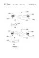
- FIG. 1provides a view of a first embodiment of the implant of this invention in which a rigid bone segment is machined to exhibit threads on each end (FIG. 1 A), and which is then demineralized only in the internal section to provide a flexible segment between the machined ends (FIG. 1 C);
- FIG. 1Bprovides a view of an alternate embodiment in which one end of the implant has a rigid fixation bone block;
- FIG. 1Dshows an end-on view of a cannulated embodiment of the implant of this invention.
- FIG. 2provides a view of a second embodiment of the implant of this invention in which a rigid bone segment is machined to exhibit threads on one end and an attachment hole at the other (FIG. 2 A), and which is then demineralized on the attachment hole end of the implant to provide a flexible segment, while retaining the threaded segment as a rigid member (FIG. 2 B).
- a partial cannulation of the implantis shown in end-on (FIG. 2 C), top (FIG. 2D) and side views (FIG. 2 E).
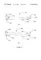
- FIG. 3provides a view of a third embodiment of the implant of this invention in which a rigid bone segment is machined to exhibit a fixation block at each end of the implant (FIG. 3 A), and which is then demineralized between the two ends to provide a flexible segment between the machined fixation block ends (FIG. 3 B).
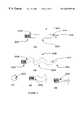
- FIG. 4provides a view of a fourth embodiment of the implant of this invention in which a rigid bone segment is machined to exhibit a fixation block at one end and an attachment hole (FIG. 4A) or several holes or perforations (FIG. 4B) at the other, and which is then demineralized at the end bearing the attachment hole(s) (FIGS. 4C and 4D) to provide a flexible segment, while retaining the fixation block end as a rigid member.
- FIG. 5shows one method of implantation of the implant of this invention in which fixation screws are utilized to retain the implant of this invention in place either by locking the implant in place through holes in the rigid segment of the implant (FIG. 5 A), or by locking the implant into place at the rigid end of the implant via a tapped recess (FIGS. 5 B and 5 C).
- FIG. 6shows an embodiment of this invention in which the implant is a femoral ring (FIG. 6A) in which the upper and lower ends of the ring are retained in a rigid, mineralized state and which may be machined to exhibit a thread or a groove, and the internal segment of the implant is demineralized to exhibit a soft spongy layer to provide flexible support upon insertion of this embodiment of the invention between adjacent vertebral bodies; alternatively, the upper, lower or both segments may be demineralized and the internal segment may be retained in a mineralized state; FIG. 6B shows this implant having angled faces; FIG. 6C shows this implant machined as a wedge.
- FIG. 6Afemoral ring
- FIG. 7shows various cross-sections (FIG. 7A, spherical; FIG. 7B, elliptical; FIG. 7C, rectangular; FIG. 7D, cross-shaped) for the mineralized or demineralized segment of the implant of this invention.
- FIG. 8depicts one embodiment of a prosthetic joint according to this invention having pointed projections for replacement of a joint (FIG. 8A) or for insertion between vertebrae (FIG. 8 B).
- FIG. 9depicts a flexible implant according to this invention for contoured repair of bone defects, including but not limited to craniomaxillofacial defects, including a first “pizza-shaped implant” (FIG. 9 A), a second “pizza-shaped implant” (FIG. 9 B), and a wrap implant having alternating mineralized and demineralized segments (FIG. 9 C).
- FIG. 10Adepicts a first embodiment and FIG. 10B depicts a second embodiment of an anterior longitudinal ligament replacement for limiting motion between adjacent vertebrae to be fused.
- FIG. 11depicts a band for limiting the motion and reducing the degradation of vertebrae juxtaposed to vertebrae undergoing fusion (i.e. as a spinal tension band) or for being affixed to any other anatomical structures to minimize motion of such structures in relation to each other.
- FIG. 12depicts a perforated sheet comprising mineralized and demineralized bone for use as a “mesh”, such as for use in a dressing or to retain particulate matter.
- FIG. 13depicts a cortical bone screw comprising at least a portion thereof which is demineralized or partially demineralized.
- This inventionprovides a biologically acceptable ligament, tendon, support or other implant for replacement of damaged ligaments, tendons, vertebral disks and the like, wherein there is a need for an implant having both a rigid machined portion or segment as well as a flexible, demineralized portion or segment.
- a segment of preferably cortical boneis machined into a desired shape, with at least one end being machined so as to provide a means for fixation of that end directly to a bone machined in a complementary fashion.
- a first embodiment of the implant of this invention 100is shown in which the ends 101 and 102 of the implant are machined so as to exhibit a thread, and the bone to which the implant is to be affixed is tapped to exhibit a receiving thread complementary to the thread on the implant end.
- the threaded ends 101 , 102may be self-tapping, thereby eliminating the need to tap the receiving bone.
- a simple hole, of a diameter slightly smaller than the diameter of the threaded implant ends,may be drilled or produced by like means to receive the threaded implant end.
- An internal segment 103 of the implantis demineralized to provide a flexible segment of the implant, while transition zones 104 , 105 are provided wherein the level of mineralization of the bone gradually changes from a fully mineralized to a demineralized state.
- the two ends 101 , 102 of the implantare machined to exhibit threads such that clockwise or counterclockwise rotation of the entire implant results in simultaneous insertion of both ends of the implant or extraction of both ends of the implant into or out of complementarily machined bones to which the implant is to be affixed, without kinking of the flexible segment 103 of the implant.
- FIG. 1Ban alternate embodiment is shown wherein one of the ends, 101 ′, is not threaded, but is machined to any desirable shape, such as a fixation block, such that the threaded end 102 may be threaded into the receiving bone, while the fixation block 101 ′ is affixed in place by interference screws or like means known in the art.
- the entire implantis machined so as to exhibit a cannulation 110 throughout its length or a portion thereof. In this fashion, the implant may be inserted over a guide-wire or like guide means.
- the aspect 110may be an internal thread capable of receiving a threaded retention screw.
- FIG. 2In a further embodiment of this invention 200 shown in FIG. 2, only one end 202 of the implant 200 is machined to exhibit a thread or another machined feature, while the other end 201 may be machined to exhibit a fixation hole 210 or a similar feature, which permits for suturing or otherwise fixing that end to a ligament or a tendon.
- a transition zone 204 from a mineralized to a demineralized stateis provided, as is a flexible segment of the implant 203 .
- FIGS. 2C-Ethere are shown an end-on view, a side view and a top view, respectively.
- an optional cannulation 220is shown, permitting threading of the machined portion 202 of the implant over a guide-wire, for example, while not interfering with the flexible, demineralized segment 203 of the implant.
- the implantmay be used to replace a ligament.
- two transition zones 304 , 305 from the flexible segment 303 to terminally mineralized fixation blocks 301 , 302are provided.
- the fixation blocks 301 and 302each have a canal 306 , 307 machined therein for receiving a fixation screw or pin.
- the mineralized sections 302 , 303may be machined into any desired form of an anchoring fixture.
- the anchoring fixturemay contain a screw thread, a hole for receipt of an anchoring pin or an anchoring screw, or a screw that rotates within a sleeve.
- the implantis used for repair or replacement of a tendon.
- only one end 402 of the implant 400is machined for fixation in a bone
- the second end 401 of the implantis adapted to a variety of shapes, terminating in a means, such as a threadable hole 410 , for fixation of that end to bone, muscle, tendon or ligament.
- the end 401 ′is machined to exhibit a plurality of holes or perforations, 410 ′, such that end 401 ′ may be sutured to a receiving biological structure, such as a muscle, ligament, tendon, bone or the like.
- FIG. 5one method of implantation of the implant 500 of this invention is shown in which fixation screws 553 are utilized to retain an embodiment of the implant 500 of this invention in a machined slot 551 in a bone 550 either by locking the implant in place (FIG. 5A) through holes 552 in the rigid segment 501 of the implant (FIG. 5 A), or by locking the implant into place at the rigid end 503 of the implant via a tapped recess (FIGS. 5 B and 5 C).
- the other end of the implant 504is demineralized, and is thus flexible, and terminates in a hole 502 or other fixation means by which that end of the implant is attached to bone, tendon, ligament or muscle.
- section 501could be threaded, end 502 could be retained in a mineralized state and could be shaped as a fixation block for retention by an interference screw, or threaded.
- the implant 500may be cannulated, with the recess 503 continuing through the entire length of the implant, or some portion thereof.
- FIG. 6Ashows an embodiment of this invention in which the implant 600 is a femoral ring member or a portion thereof wherein the upper and lower ends or faces 602 , 604 are retained in a rigid, mineralized state and which may be machined to exhibit a thread or a groove by means known in the art (see WO 97/25945, hereby incorporated by reference for this purpose).
- the internal segment of the implant 603is demineralized to exhibit a soft spongy region to provide flexible support upon insertion of this embodiment of the invention between, for example, adjacent vertebral bodies.
- An internal canal 601is shown in the femoral ring, which derives from the natural intramedullary canal of the bone from which the femoral ring is obtained by substantially planar, parallel cross-cuts across the diaphysis of a femur or like long bone. Alternatively, a transverse cut to form a dowel which is then segmentally demineralized is also contemplated.
- the canalmay be left open or filled with osteogenic factors, including but not limited to autologous bone or marrow.
- the canalmay be filled with a carrier and growth factors, including but not limited to bone morphogenetic proteins, demineralized bone matrix (DBM), or any inert or biologically active substance considered beneficial for insertion into the spine to assist in support thereof or for fusion of adjacent vertebrae.
- the canalmay retain the natural architecture of the intramedullary canal or it may be scraped out or otherwise modified.
- the upper end 601 , the lower end 604 , or bothmay be demineralized, while the internal segment 603 of the implant may be maintained in a mineralized state.
- the upper 602 and lower 604 faces of the implantmay not be parallel, but rather may slope toward each other, as shown for embodiment 610 in FIG. 6B, such that H1 is greater than H2.
- the upper and lower facesmay exhibit curvature and external features, such as grooves, pits or protrusions to assist in the retention of the implant when inserted between adjacent vertebrae.
- the slant of the upper and lower facesshould be such that the natural lordosis of the spinal segment into which the implant is inserted is maintained.
- the shape of the implantmay include a substantially circular, elliptical, rectangular or like shape. As shown in FIG.
- the implantmay comprise a portion of the femoral ring, exhibiting a greater width W 1 and a lesser width W 2 .
- the upper surface, lower surface or both surfacesmay comprise features such as grooves, pits, indents, teeth or protrusions to inhibit slippage or expulsion of the implant.
- the implant of this inventioncomprising a segmentally demineralized bone comprising at least one mineralized portion or segment, and at least one flexible, demineralized portion or segment is produced by machining a piece of preferably cortical bone into any desired shape.
- the boneis preferably chosen to be strong cortical bone, such as from the femur, tibia, fibula, radius or ulna.
- the source of the donor bonemay be autograft, allograft or xenograft bone, with the appropriate cautionary steps known in the art being taken in each case to prevent introduction into the recipient of pathogenic or antigenic agents.
- a segment of the implantis preferably machined to exhibit a thread or like fixation means whereby the implant may be directly affixed to recipient bone machined in a complementary fashion. That segment of the implant is retained in a mineralized state, by appropriately protecting that segment of the implant with any protective device, such as with parafilm, a rubber or latex covering, plastic wrap, and the like.
- the remaining segment of the implantis then demineralized according to methods known in the art. For example, in the embodiment 100 of this invention shown in FIG.
- both ends 101 , 102may be inserted into rubber stoppers spanning the transition zones 104 , 105 , and the internal segment 103 , is exposed to an acid solution of sufficient strength to leach the minerals from that segment of the bone.
- a 5% acetic acid solution or a 1 N hydrochloric acid solutionmay be employed, and the implant checked periodically for the desired level of flexibility of the internal zone 103 . It is important that an excessively high concentration of strong acid not be employed for this process, as this will result in cleavage of the peptide bonds of the collagenous matrix within which the minerals are deposited.
- HCl concentrationsof between about 0.1N to 2N are acceptable, with the period of exposure to acid being increased for the lower acid concentrations and decreased for the higher acid concentrations.
- the transition zones 104 , 105are formed by diffusion of the acid into and diffusion of the minerals out of the bone in that segment of the implant covered by the protective covering.
- the implant of this inventionmay be prepared by appropriately masking portions of the implant, using a tape, rubber, latex or any other material which may be adhered to any portion of the bone, to prevent demineralization of portions thereof.
- the implantis produced by masking portions of a flat segment of cortical bone, to form a striated “pizza-slice-shaped” implant device, as shown in FIG. 9 .
- a shape, such as a substantially hexagonal piece of cortical bone 900is demineralized after application of masking means 910 such that intermediate sections 920 are demineralized while zones of mineralized bone remain where masked at 910 .
- FIG. 9Alternatively, as shown in FIG.
- an implant 950is produced wherein zones 960 are protected from the demineralizing agent (acid, chelating agents, and the like), while areas 970 are not protected.
- demineralizing agentacid, chelating agents, and the like
- the resultis a pizza-slice-shaped implant 950 having flexible hinge portions with mineralized pizza-slice-shaped portions 960 which retain mineral and rigidity.
- An implant such as 900 or 950has application, for example, in the repair of craniofacial or craniomaxillofacial defects, among other possible applications.
- 9Cmay be produced from a sheet of cortical bone with alternating mineralized 990 and demineralized 985 zones for wrapping around a piece of fractured bone, for example.
- the mineralized portion of the bone-wrapacts as a splint while the flexible, demineralized portion of the bone-wrap permits the implant to wrap around the fractured bone segment.
- the flexibility of the implantpermits the implant to be contoured to the surface of a bone defect area to repair such defect.
- implants of a wide variety of shapes, sizes and applicationsmay be produced in a similar manner wherein a portion of the implant retains a rigid mineralized portion and a portion of the implant is at least partially demineralized to produce a flexible portion of the implant.
- sheets of bone, partially demineralized wrapping sheets and the likeare all variations on this theme which come within the scope of the instant invention.
- a partial demineralization of the surface of bone implantshas been found to be beneficial in that modification of the stress-fracture behavior of the bone may thus be achieved. Accordingly, depletion of up to about 25 percent of the natural bone mineral may be achieved by limited demineralization to break up the bone crystal structure in the partially demineralized portion of the implant. As a result, reduction in the variability of the stress load at which bone fractures upon stress of the bone has been noted, even when as little as a one percent reduction in the bone mineral content is used. This observation may be combined with embodiments of the implant of this invention wherein a portion of the implant is maintained in a rigid, mineralized state, while at least one portion of the implant is demineralized or partially demineralized.
- the implant of this inventionmay be further treated by tanning or other means known in the art to reduce the antigenicity of the implant.
- glutaraldehyde treatmentsee U.S. Pat. No. 5,053,049, hereby incorporated by reference for this purpose
- the implantmay be subjected to treatment with chaotropic agents, including but not limited to urea, guanidine hydrochloride, combinations thereof and like agents, to remove noncovalent immunogens.
- Treatment with reducing agents, detergents, chelating agents and the likemay also be beneficially applied, depending on the nature of the bone implant and its source. For example, where xenograft bone is used as the material for implant production, reduction in the antigenicity of the bone becomes much more important than if autograft or allograft bone is used.
- FIG. 7various cross-sectional shapes of the implant of this invention are shown.
- a cylindrical cross-sectionis shown.
- various diametersfrom as small as 0.5 mm or smaller to as large as 10 mm, or in certain applications, even larger, may be desirable.
- FIG. 7Ban oval cross-section is provided.
- FIG. 7Ca flat cross section is provided.
- FIG. 7Da cross-shaped cross-section is provided.
- the implant of this inventionmay be appropriately fashioned for a wide diversity of applications.
- an implant of this inventionmay be applied to repair of ligaments or tendons in the hand, elbow, knee, foot, ankle or any other anatomical location as needed.
- the implant of this inventionmay be applied to replacement any of a variety of joints. Methods and implant shapes known in the art for joint replacement, (see, for example U.S. Pat. Nos. 4,871,367; Des. 284,099; Des. 277,784; Des.
- a piece of cortical boneis shaped so as to form a surgically implantable prosthetic joint having a load distributing flexible hinge, analogous to that disclosed in U.S. Pat. No. 3,875,594 (which was made from molded silicone rubber).
- a prosthesisis formed consisting of an enlarged midsection, and a pair of oppositely projecting distal and proximal stem portions.
- the volar aspect of the midsectionis machined to exhibit an indent or transverse channel extending across its width, to form the flexible hinge upon demineralization of the midsection.
- the midsection, intended to act as the hinge,is demineralized, and the mineralized extremities of the implant are retained in a mineralized state for insertion of each end into the intramedullary space of the bones adjacent to the joint which the implant replaces.
- the mineralized extremitiesare machined to exhibit a thread or a ratcheting tooth structure, such that upon insertion of each end into the intramedullary space of the adjacent bones, the end is fixed in place. Since the ends are made from bone, the natural process of fusion between the implant and the bone into which it is inserted occurs over several weeks, thus permanently fixing the prosthesis into position and preventing any movement of the ends of the implant. Implants according to this embodiment of the invention may be used, for example, to replace metacarpophalangeal joints, proximal interphalangeal joints and the like. Accordingly, this invention represents a significant advance in the art as it provides a natural alternative to currently employed metallic, hydroxyapatite, silastic, silicone or like elastomeric materials for joint arthroplasty.
- FIG. 8Athere is provided one diagrammatic representation of an implant of a prosthetic joint according to this invention and which may be prepared according to the concepts central to the instant invention.
- the implant 800has an enlarged midsection 810 which is demineralized up to and including a portion of the transition segment 820 .
- On either side of the midsection 810are mineralized projections 830 adapted for insertion into the intramedullary canals of bones adjacent to the joint which the implant 800 replaces.
- a groove or channel 850is provided to act as the hinge and to allow being motion of the joint according to principles described in U.S. Pat. No. 3,875,594, herein incorporated by reference for this purpose.
- the projections 830may exhibit an external feature designed to enhance retention of the implant in the intramedullary spaces.
- this featureis shown as a tooth-like serration 840 which may be machined into an upper or lower aspect of each projection 830 or which may project around the circumference of the projections.
- Alternate external features which may aid in retention of the implantinclude holes through which retention pins may be inserted, grooves, ribbings and the like.
- the demineralized midsection 810permits the implant 800 sufficient flexibility to allow that portion of the implant to act as a joint, while the projections 830 fuse with the bone into which they are inserted to form a permanent fixation. It will be appreciated that, as shown in FIG.
- an implant 860 similar to that shown in FIG. 8Amay be implemented for inducing spinal fusion, whereby an intermediate section 870 is demineralized while extension thereof 880 are retained in a mineralized state.
- an intermediate section 870is demineralized while extension thereof 880 are retained in a mineralized state.
- the height H1may be greater or smaller than the height H2.
- the upper surface 885 , the lower surface 886 , or bothmay comprise features such as grooves, pits, or projections which help retain the implant between vertebrae when inserted into an intervertebral space.
- ALLsegmentally demineralized anterior longitudinal ligament
- An ALL produced according to the method of this inventionmay be used to advantage to prevent expulsion of interbody grafts, and is preferably affixed to the vertebral bodies with screws, pins, staples or anchors of various types know in the art or heretofore developed. As a result, lumbar extension is reduced, thereby providing a more stable environment to promote fusion.
- FIG. 10there is provided one embodiment 1000 of the ALL according to this invention.
- the ALL 1000is prepared from the distal femur or other flat cortical surface, such as the proximal humerus or tibia.
- a top portion 1010 and a bottom portion 1020is retained in a mineralized state, or is only partially demineralized, or is surface demineralized to modify the stress-fracture behavior of that portion of the implant.
- the top portion 1010 and the bottom portion 1020each have a series of holes 1005 by means of which the ALL is affixed to a superior vertebra V 1 and an inferior vertebra V 2 .
- An intermediate section, 1030is demineralized, to an extent sufficient to permit that segment of the ALL to have a degree of flexibility.
- the ALLsubstantially restricts motion at the vertebral segment spanned by the ALL.
- a pair of interbody implants 1040inserted between superior vertebra V 1 and inferior vertebra V 2 , spanned by the ALL, in order to induce fusion between V 1 and V 2 .
- FIG. 10Bthere is shown a further embodiment 1000 ′ of the ALL of this invention which is identical in all respects to the implant shown in FIG. 10A, but wherein this embodiment has an enlarged upper segment 1010 ′ and lower segment 1020 ′ for affixation to the vertebrae V 1 and V 2 .
- the precise shape of the ALLis not critical.
- the ALLmay span more than two vertebrae.
- a spinal tension bandSTB.
- the motion segment adjacent to the fused segmenthave been found to rapidly degrade. This degradation appears to be due to the hypermotion at these levels, due to the decreased motion at the juxtaposed fused segments.
- the STB of this inventionassists in preventing this degradation and can avoid the need for further surgery, by spanning the fused segments and attaching to the juxtaposed vertebral body at the spinous process thereof.
- the STBmay be used in any region of the spin, but is typically most useful for spanning fusions at two, three or more levels.
- the STB of this inventionreplaces or augments use of flexible stainless steel, titanium cables, elastomeric or polymeric synthetic materials currently in use. Accordingly, known techniques for attaching such devices to the spinous processes may be used, or the STB may be affixed to juxtaposed vertebral bodies in a fashion analogous to that described above for the ALL.
- FIG. 11there is disclosed one embodiment of the STB 1100 of this invention. As can be seen, the STB 1100 is affixed to a superior vertebrae, VA, and an inferior vertebra, VB, each of which are juxtaposed to a vertebrae V 1 and V 2 , which are being fused to each other by means of interbody fusion devices IB 1 and IB 2 .
- Intermediate portion 1110 of the STBmay be demineralized, while the top portion 1120 and bottom portion 1130 may be retained in a mineralized or partially demineralized state.
- Fixation means 1125 and 1135are provided for fixation of the STB to the juxtapose vertebrae VA and VB, respectively.
- this embodiment of the inventionmay be applied to any other anatomical structures to minimize motion of such structures in relation to each other.
- the tension band of this inventionmay be utilized outside of the spinal context, such as for repair of a split sternum in a sternotomy.
- FIG. 12there is shown a further embodiment 1200 of the implant of this invention in the form of a sheet 1205 having a plurality of perforations 1206 comprising mineralized 1210 and demineralized 1220 segments.
- the perforated segmentally demineralized sheet of this embodiment of the inventionmay be used as a wrap or as a retention means for particulate material, gel material and the like when deposited on, in or around a bone, for example.
- Compositions which may be used in connection with this embodiment of the inventioninclude osteogenic bone paste and the like.
- FIG. 13there is shown a further embodiment 1300 of the implant of this invention in the form of a screw made from cortical bone, comprising at least a portion thereof which is demineralized or partially demineralized.
- desirable physical characteristics, and in vivo remodeling characteristics of such a devicemay be achieved by demineralizing or partially demineralizing various segments of the screw.
- the point 1310 of the screwmay be mineralized while the thread 1320 or drive head 1330 may be partially demineralized, to provide desirable surface characteristics, including but not limited to greater capacity for in vivo remodeling or minimized stress-fracture characteristics.
- the starting bone stockwas chosen such that a piece of bone consisting substantially of cortical bone was used to machine the implant of this invention. Implants from the linea aspera of the femur or an anterior aspect of the tibia were used for this purpose, but other cortical sources of bone would be acceptable.
- the desired bone segmentwas removed with a bone saw or a water-cooled diamond core cutter, and trimmed to fit in a lathe for machining of desired external features.
- the bonewas first machined to a known diameter and length.
- the endswere then machined to exhibit an internal thread, an external thread, or to have one machined end while the other end of the implant was drilled to exhibit one to several holes.
- the internal segment destined for demineralizationwas then either retained in a cylindrical form or machined in a milling machine or a grinder, to exhibit a flat internal segment, or another desired shape, between the threaded ends or the fixation ends.
- Demineralization of a machined large cylindrical ligament repair graftwas completed in three days using approximately 40 mL of 0.75M-1.0M hydrochloric acid solution.
- the implantwas exposed to fresh solution at least once per day.
- the point of contact of the HCl solution with the implantwas varied over the duration of the demineralization process.
- Demineralization of a machined small cylindrical ligament repair graftwas completed in two days using approximately 40 mL of 0.75M-1.0M hydrochloric acid solution.
- the implantwas exposed to fresh solution at least once per day.
- the point of contact of the HCl solution with the implantwas varied over the duration of the demineralization process.
- Demineralization of a machined ligament or tendon repair graft wherein an internal segment of the graft was machined flatwas completed in twenty-four hours using approximately 40 mL of 0.75M-1.0M hydrochloric acid solution.
- the implantwas exposed to fresh solution at least once per day.
- the point of contact of the HCl solution with the implantwas varied over the duration of the demineralization process.
- Demineralization of a machined, flat ligament repair graftwas completed in twenty-four hours using approximately 40 mL of 0.75M-1.0M hydrochloric acid solution.
- the implantwas exposed to fresh solution at least once per day.
- the point of contact of the HCl solution with the implantwas varied over the duration of the demineralization process.
- the implantwas exposed to the acid solution only in the middle segment by keeping the threaded end of the implant above the meniscus of the acid, and the fixation block end of the implant was inserted into a bored-out stopper, which also acted as a plug at the bottom of the acid container, into which a hole adequate to receive the implant bearing stopper had been drilled.
- a flat cortical segment of boneis partially demineralized to form an ALL replacement or an STB, for stabilization of portions of the spine undergoing fusion.
- the ALLis affixed to two adjacent vertebrae undergoing fusion, while the STB is affixed to vertebrae juxtaposed to vertebrae undergoing fusion.
- the mineralized portion of the ALL and STBare utilized to affix the implants to the vertebrae by means of cortical bone screws, metallic pins or by hooking demineralized portions of the ALL or STB over vertebral processes. Craniomaxillofacial implantation of a pizza shaped implant such as that shown in FIG.
- a sheet of cortical boneis segmentally masked such that adjacent liner segments of alternating mineralized and demineralized bone are produced upon contact of the masked bone to demineralizing agents such as acetic acid, hydrochloric acid, chelating agents, and the like.
- demineralizing agentssuch as acetic acid, hydrochloric acid, chelating agents, and the like.
- the bone-wrapis wrapped around a segment of fractured bone to provide support and to contain added osteogenic compositions to maximize repair of the fractured bone.
Landscapes
- Health & Medical Sciences (AREA)
- Life Sciences & Earth Sciences (AREA)
- Engineering & Computer Science (AREA)
- Biomedical Technology (AREA)
- Public Health (AREA)
- Transplantation (AREA)
- Oral & Maxillofacial Surgery (AREA)
- Animal Behavior & Ethology (AREA)
- General Health & Medical Sciences (AREA)
- Veterinary Medicine (AREA)
- Chemical & Material Sciences (AREA)
- Orthopedic Medicine & Surgery (AREA)
- Heart & Thoracic Surgery (AREA)
- Vascular Medicine (AREA)
- Cardiology (AREA)
- Medicinal Chemistry (AREA)
- Epidemiology (AREA)
- Dermatology (AREA)
- Botany (AREA)
- Chemical Kinetics & Catalysis (AREA)
- Molecular Biology (AREA)
- Zoology (AREA)
- Rehabilitation Therapy (AREA)
- Rheumatology (AREA)
- Cell Biology (AREA)
- Urology & Nephrology (AREA)
- Manufacturing & Machinery (AREA)
- Prostheses (AREA)
Abstract
Description
Claims (7)
Priority Applications (2)
| Application Number | Priority Date | Filing Date | Title |
|---|---|---|---|
| US09/417,401US6652592B1 (en) | 1997-10-27 | 1999-10-13 | Segmentally demineralized bone implant |
| US09/778,046US20010020188A1 (en) | 1997-10-27 | 2001-02-05 | Selective uptake of materials by bone implants |
Applications Claiming Priority (2)
| Application Number | Priority Date | Filing Date | Title |
|---|---|---|---|
| US08/958,364US6090998A (en) | 1997-10-27 | 1997-10-27 | Segmentally demineralized bone implant |
| US09/417,401US6652592B1 (en) | 1997-10-27 | 1999-10-13 | Segmentally demineralized bone implant |
Related Parent Applications (1)
| Application Number | Title | Priority Date | Filing Date |
|---|---|---|---|
| US08/958,364Continuation-In-PartUS6090998A (en) | 1997-10-27 | 1997-10-27 | Segmentally demineralized bone implant |
Related Child Applications (1)
| Application Number | Title | Priority Date | Filing Date |
|---|---|---|---|
| US51800000AContinuation-In-Part | 1997-10-27 | 2000-03-02 |
Publications (1)
| Publication Number | Publication Date |
|---|---|
| US6652592B1true US6652592B1 (en) | 2003-11-25 |
Family
ID=29584941
Family Applications (1)
| Application Number | Title | Priority Date | Filing Date |
|---|---|---|---|
| US09/417,401Expired - Fee RelatedUS6652592B1 (en) | 1997-10-27 | 1999-10-13 | Segmentally demineralized bone implant |
Country Status (1)
| Country | Link |
|---|---|
| US (1) | US6652592B1 (en) |
Cited By (103)
| Publication number | Priority date | Publication date | Assignee | Title |
|---|---|---|---|---|
| US20030167092A1 (en)* | 2001-02-06 | 2003-09-04 | Foley Kevin T. | Spinal bone implant |
| US20040215341A1 (en)* | 2000-12-08 | 2004-10-28 | Sybert Daryl R | Biocompatible osteogenic band for repair of spinal disorders |
| US20050159812A1 (en)* | 2004-01-16 | 2005-07-21 | Dinger Fred B.Iii | Bone-tendon-bone implant |
| US20050229323A1 (en)* | 2004-04-20 | 2005-10-20 | Mills C R | Process and apparatus for treating implants comprising soft tissue |
| US20060178752A1 (en)* | 1998-11-20 | 2006-08-10 | Yaccarino Joseph A Iii | Compound bone structure of allograft tissue with threaded fasteners |
| US20060200235A1 (en)* | 2005-03-04 | 2006-09-07 | Regeneration Technologies, Inc. | Assembled bone-tendon-bone grafts |
| US20060212036A1 (en)* | 2005-03-04 | 2006-09-21 | Regeneration Technologies, Inc. | Bone block assemblies and their use in assembled bone-tendon-bone grafts |
| US20060228252A1 (en)* | 2004-04-20 | 2006-10-12 | Mills C R | Process and apparatus for treating implants comprising soft tissue |
| US20060271192A1 (en)* | 2005-03-04 | 2006-11-30 | Olsen Raymond E | Self Fixing Assembled Bone-Tendon-Bone Graft |
| US20070129804A1 (en)* | 2005-12-07 | 2007-06-07 | Zimmer Spine, Inc. | Transforaminal lumbar interbody fusion spacers |
| US20070162122A1 (en)* | 2005-12-20 | 2007-07-12 | Whittaker Gregory R | Methods for ligament reconstruction |
| US20070168030A1 (en)* | 1999-06-08 | 2007-07-19 | Edwards Jean T | Osteoimplant and Method for Making Same |
| USD554260S1 (en)* | 2006-06-14 | 2007-10-30 | Ric Investments, Llc | Oral appliance device |
| USD554259S1 (en)* | 2006-06-14 | 2007-10-30 | Ric Investments, Llc | Oral appliance tray |
| EP1800608A3 (en)* | 2005-12-20 | 2008-02-13 | DePuy Mitek, Inc. | Materials and method for ligament reconstruction |
| USD565179S1 (en)* | 2005-06-16 | 2008-03-25 | Pentax Corporation | Bone implant |
| US20080091270A1 (en)* | 2005-01-14 | 2008-04-17 | Miller Timothy R | Expandable osteoimplant |
| US20080294270A1 (en)* | 2007-05-24 | 2008-11-27 | Zimmer Orthobiologics, Inc. | Differentially processed tissue and processing methods thereof |
| US20090005882A1 (en)* | 2001-02-28 | 2009-01-01 | Boyer Iii Michael L | Demineralized bone-derived implants |
| US20090018560A1 (en)* | 2007-04-20 | 2009-01-15 | Woodwelding Ag | Method for fastening an implant to bone tissue and corresponding implant system |
| US7517358B2 (en) | 2004-11-22 | 2009-04-14 | Orthopedic Development Corporation | Implant device used in minimally invasive facet joint hemi-arthroplasty |
| US7708761B2 (en) | 2004-11-22 | 2010-05-04 | Minsurg International, Inc. | Spinal plug for a minimally invasive facet joint fusion system |
| US7799084B2 (en) | 2002-10-23 | 2010-09-21 | Mako Surgical Corp. | Modular femoral component for a total knee joint replacement for minimally invasive implantation |
| US7815926B2 (en) | 2005-07-11 | 2010-10-19 | Musculoskeletal Transplant Foundation | Implant for articular cartilage repair |
| US7837740B2 (en) | 2007-01-24 | 2010-11-23 | Musculoskeletal Transplant Foundation | Two piece cancellous construct for cartilage repair |
| USRE42208E1 (en) | 2003-04-29 | 2011-03-08 | Musculoskeletal Transplant Foundation | Glue for cartilage repair |
| US7901457B2 (en) | 2003-05-16 | 2011-03-08 | Musculoskeletal Transplant Foundation | Cartilage allograft plug |
| US7939108B2 (en) | 2000-12-14 | 2011-05-10 | Osteotech, Inc. | Method of making demineralized bone particles |
| US7959941B2 (en) | 2001-10-12 | 2011-06-14 | Warsaw Orthopedic, Inc. | Bone graft comprising a demineralized bone matrix and a stabilizing agent |
| US8002813B2 (en) | 1999-10-15 | 2011-08-23 | Warsaw Orthopedic, Inc. | Volume maintaining osteoinductive/osteoconductive compositions |
| US8021392B2 (en) | 2004-11-22 | 2011-09-20 | Minsurg International, Inc. | Methods and surgical kits for minimally-invasive facet joint fusion |
| US8128703B2 (en) | 2007-09-28 | 2012-03-06 | Depuy Products, Inc. | Fixed-bearing knee prosthesis having interchangeable components |
| US8268008B2 (en) | 2003-06-11 | 2012-09-18 | Warsaw Orthopedic, Inc. | Osteoimplants and methods for their manufacture |
| US8287601B2 (en) | 2010-09-30 | 2012-10-16 | Depuy Products, Inc. | Femoral component of a knee prosthesis having an angled cement pocket |
| US8292968B2 (en) | 2004-10-12 | 2012-10-23 | Musculoskeletal Transplant Foundation | Cancellous constructs, cartilage particles and combinations of cancellous constructs and cartilage particles |
| US8317870B2 (en) | 2010-09-30 | 2012-11-27 | Depuy Products, Inc. | Tibial component of a knee prosthesis having an angled cement pocket |
| US8328807B2 (en) | 2008-07-09 | 2012-12-11 | Icon Orthopaedic Concepts, Llc | Ankle arthrodesis nail and outrigger assembly |
| US8414584B2 (en) | 2008-07-09 | 2013-04-09 | Icon Orthopaedic Concepts, Llc | Ankle arthrodesis nail and outrigger assembly |
| US8435551B2 (en) | 2007-03-06 | 2013-05-07 | Musculoskeletal Transplant Foundation | Cancellous construct with support ring for repair of osteochondral defects |
| US8470038B2 (en) | 2005-03-04 | 2013-06-25 | Rti Biologics, Inc. | Adjustable and fixed assembled bone-tendon-bone graft |
| US8545864B2 (en) | 2005-11-02 | 2013-10-01 | Warsaw Orthopedic, Inc. | Hemostatic bone graft |
| US20130282128A1 (en)* | 2012-04-24 | 2013-10-24 | Warsaw Orthopedic, Inc. | Facet joint implant device |
| WO2013169366A1 (en) | 2012-05-11 | 2013-11-14 | Rti Biologics, Inc. | Xenograft soft tissue implants and methods of making and using |
| US8663672B2 (en) | 2000-07-19 | 2014-03-04 | Warsaw Orthopedic, Inc. | Osteoimplant and method of making same |
| US8702809B2 (en) | 2007-09-14 | 2014-04-22 | Purdue Research Foundation | Demineralized cancellous bone scaffolds |
| US8722075B2 (en) | 2008-10-24 | 2014-05-13 | Warsaw Orthopedic, Inc. | Compositions and methods for promoting bone formation |
| USD705930S1 (en)* | 2013-06-12 | 2014-05-27 | Biomedical Enterprises, Inc. | Orthopedic staple |
| US8753406B2 (en) | 2010-08-31 | 2014-06-17 | Zimmer Inc. | Osteochondral graft delivery device and uses thereof |
| USD707357S1 (en)* | 2013-06-12 | 2014-06-17 | Biomedical Enterprises, Inc. | Orthopedic staple |
| US9011547B2 (en) | 2010-01-21 | 2015-04-21 | Depuy (Ireland) | Knee prosthesis system |
| US9204967B2 (en) | 2007-09-28 | 2015-12-08 | Depuy (Ireland) | Fixed-bearing knee prosthesis having interchangeable components |
| US9289240B2 (en) | 2005-12-23 | 2016-03-22 | DePuy Synthes Products, Inc. | Flexible elongated chain implant and method of supporting body tissue with same |
| US9398956B2 (en) | 2007-09-25 | 2016-07-26 | Depuy (Ireland) | Fixed-bearing knee prosthesis having interchangeable components |
| US9701940B2 (en) | 2005-09-19 | 2017-07-11 | Histogenics Corporation | Cell-support matrix having narrowly defined uniformly vertically and non-randomly organized porosity and pore density and a method for preparation thereof |
| US9724207B2 (en) | 2003-02-14 | 2017-08-08 | DePuy Synthes Products, Inc. | In-situ formed intervertebral fusion device and method |
| US9801725B2 (en) | 2009-12-09 | 2017-10-31 | DePuy Synthes Products, Inc. | Aspirating implants and method of bony regeneration |
| WO2017201259A1 (en) | 2016-05-18 | 2017-11-23 | Rti Surgical, Inc. | Osteoinductive nanofiber scaffold for bone regeneration |
| US9943416B2 (en) | 2015-03-10 | 2018-04-17 | Simplify Medical Pty Limited | Intervertebral spacer that dynamically promotes bone growth |
| US20180207317A1 (en)* | 2013-08-06 | 2018-07-26 | Mark Schumacher | Method for fusion of fractured or voided sternum post sternotomy |
| US10077420B2 (en) | 2014-12-02 | 2018-09-18 | Histogenics Corporation | Cell and tissue culture container |
| US20190000628A1 (en)* | 2011-02-28 | 2019-01-03 | DePuy Synthes Products, Inc. | Modular tissue scaffolds |
| US10531957B2 (en) | 2015-05-21 | 2020-01-14 | Musculoskeletal Transplant Foundation | Modified demineralized cortical bone fibers |
| US10779816B2 (en) | 2016-07-07 | 2020-09-22 | Medline Industries, Inc. | Orthopedic implant, method, and kit |
| US10888433B2 (en) | 2016-12-14 | 2021-01-12 | DePuy Synthes Products, Inc. | Intervertebral implant inserter and related methods |
| US10940016B2 (en) | 2017-07-05 | 2021-03-09 | Medos International Sarl | Expandable intervertebral fusion cage |
| US10945830B2 (en) | 2017-10-06 | 2021-03-16 | Paragon 28, Inc. | Ligament fixation system, implants, devices, and methods of use |
| US10966840B2 (en) | 2010-06-24 | 2021-04-06 | DePuy Synthes Products, Inc. | Enhanced cage insertion assembly |
| US10973652B2 (en) | 2007-06-26 | 2021-04-13 | DePuy Synthes Products, Inc. | Highly lordosed fusion cage |
| US11026732B2 (en) | 2017-10-25 | 2021-06-08 | Paragon 28, Inc. | Ligament fixation system, implants, and devices with a compression cap, and methods of use |
| JP2021523749A (en)* | 2019-01-17 | 2021-09-09 | 浙江大学医学院附属邵逸夫医院Sir Run Run Shaw Hosoital Zhejiang University School of Medicine | Method for preparing extracellular matrix material for gradient mineralized bone |
| US11179234B2 (en) | 2017-09-15 | 2021-11-23 | Paragon 28, Inc. | Ligament fixation system, implants, devices, and methods of use |
| US11207191B2 (en) | 2015-03-10 | 2021-12-28 | Simplify Medical Pty Ltd | Intervertebral spacer that dynamically promotes bone growth |
| WO2022018699A1 (en)* | 2020-07-23 | 2022-01-27 | Universidad De Los Andes | Implants and production methods of products for bone regeneration |
| US11273050B2 (en) | 2006-12-07 | 2022-03-15 | DePuy Synthes Products, Inc. | Intervertebral implant |
| US11344424B2 (en) | 2017-06-14 | 2022-05-31 | Medos International Sarl | Expandable intervertebral implant and related methods |
| US11426286B2 (en) | 2020-03-06 | 2022-08-30 | Eit Emerging Implant Technologies Gmbh | Expandable intervertebral implant |
| US11426290B2 (en) | 2015-03-06 | 2022-08-30 | DePuy Synthes Products, Inc. | Expandable intervertebral implant, system, kit and method |
| US11446156B2 (en) | 2018-10-25 | 2022-09-20 | Medos International Sarl | Expandable intervertebral implant, inserter instrument, and related methods |
| US11446155B2 (en) | 2017-05-08 | 2022-09-20 | Medos International Sarl | Expandable cage |
| US11452607B2 (en) | 2010-10-11 | 2022-09-27 | DePuy Synthes Products, Inc. | Expandable interspinous process spacer implant |
| US11497619B2 (en) | 2013-03-07 | 2022-11-15 | DePuy Synthes Products, Inc. | Intervertebral implant |
| US11510788B2 (en) | 2016-06-28 | 2022-11-29 | Eit Emerging Implant Technologies Gmbh | Expandable, angularly adjustable intervertebral cages |
| US11596523B2 (en) | 2016-06-28 | 2023-03-07 | Eit Emerging Implant Technologies Gmbh | Expandable and angularly adjustable articulating intervertebral cages |
| US11602438B2 (en) | 2008-04-05 | 2023-03-14 | DePuy Synthes Products, Inc. | Expandable intervertebral implant |
| US11607321B2 (en) | 2009-12-10 | 2023-03-21 | DePuy Synthes Products, Inc. | Bellows-like expandable interbody fusion cage |
| US11612493B2 (en) | 2003-06-30 | 2023-03-28 | DePuy Synthes Products, Inc. | Intervertebral implant with conformable endplate |
| US11612491B2 (en) | 2009-03-30 | 2023-03-28 | DePuy Synthes Products, Inc. | Zero profile spinal fusion cage |
| US11654033B2 (en) | 2010-06-29 | 2023-05-23 | DePuy Synthes Products, Inc. | Distractible intervertebral implant |
| US11737881B2 (en) | 2008-01-17 | 2023-08-29 | DePuy Synthes Products, Inc. | Expandable intervertebral implant and associated method of manufacturing the same |
| US11752009B2 (en) | 2021-04-06 | 2023-09-12 | Medos International Sarl | Expandable intervertebral fusion cage |
| USD1003436S1 (en) | 2021-08-19 | 2023-10-31 | Medline Industries, Lp | Surgical staple |
| USD1004088S1 (en) | 2021-08-19 | 2023-11-07 | Medline Industries, Lp | Surgical staple |
| US11850160B2 (en) | 2021-03-26 | 2023-12-26 | Medos International Sarl | Expandable lordotic intervertebral fusion cage |
| US11890320B2 (en) | 2015-04-20 | 2024-02-06 | The Board Of Regents Of The University Of Texas System | CLEC11A is a bone growth agent |
| US11911287B2 (en) | 2010-06-24 | 2024-02-27 | DePuy Synthes Products, Inc. | Lateral spondylolisthesis reduction cage |
| USRE49973E1 (en) | 2013-02-28 | 2024-05-21 | DePuy Synthes Products, Inc. | Expandable intervertebral implant, system, kit and method |
| US12090064B2 (en) | 2022-03-01 | 2024-09-17 | Medos International Sarl | Stabilization members for expandable intervertebral implants, and related systems and methods |
| US12220123B2 (en) | 2021-08-19 | 2025-02-11 | Medline Industries, Lp | Apparatus and methods for joining bones |
| US12295625B2 (en) | 2021-08-19 | 2025-05-13 | Medline Industries, Lp | Apparatus and methods for joining bones |
| US12303377B2 (en) | 2019-09-12 | 2025-05-20 | Paragon 28, Inc. | Dynamic fixation implant and method of use |
| US12336704B2 (en) | 2023-01-13 | 2025-06-24 | Medline Industries, Lp | Apparatus and methods for joining bones |
| US12376850B2 (en) | 2023-06-22 | 2025-08-05 | Medline Industries, Lp | Surgical staple |
| US12440346B2 (en) | 2023-03-31 | 2025-10-14 | DePuy Synthes Products, Inc. | Expandable intervertebral implant |
Citations (38)
| Publication number | Priority date | Publication date | Assignee | Title |
|---|---|---|---|---|
| US3772709A (en) | 1972-06-15 | 1973-11-20 | A Swanson | Prosthetic joint |
| US3875594A (en) | 1973-08-27 | 1975-04-08 | Dow Corning | Surgically implantable prosthetic joint having load distributing flexible hinge |
| US3886600A (en) | 1971-07-15 | 1975-06-03 | Cutter Lab | Joint prosthesis |
| USD277509S (en) | 1982-07-01 | 1985-02-05 | Sutter Biomedical Inc. | Great toe metatarsal phalangeal implant |
| USD277784S (en) | 1982-06-25 | 1985-02-26 | Sutter Biomedical, Inc. | Lesser toe metatarsal phalangeal implant |
| US4553272A (en) | 1981-02-26 | 1985-11-19 | University Of Pittsburgh | Regeneration of living tissues by growth of isolated cells in porous implant and product thereof |
| USD284099S (en) | 1983-03-14 | 1986-06-03 | Sutter Bio-Medical, Inc. | Great toe metatarsal phalangeal implant |
| US4627853A (en) | 1985-05-29 | 1986-12-09 | American Hospital Supply Corporation | Method of producing prostheses for replacement of articular cartilage and prostheses so produced |
| US4743259A (en) | 1986-10-29 | 1988-05-10 | The University Of Virginia Alumni Patents Foundation | Use of demineralized bone matrix in the repair of segmental defects |
| US4759768A (en) | 1987-02-11 | 1988-07-26 | Thierry Hermann | Joint prosthesis, in particular finger joint prosthesis |
| US4772286A (en) | 1987-02-17 | 1988-09-20 | E. Marlowe Goble | Ligament attachment method and apparatus |
| US4839215A (en) | 1986-06-09 | 1989-06-13 | Ceramed Corporation | Biocompatible particles and cloth-like article made therefrom |
| US4871367A (en) | 1987-09-03 | 1989-10-03 | Sutter Biomedical Corporation | Surgically implanted prosthesis |
| EP0356112A1 (en) | 1988-08-18 | 1990-02-28 | University Of Medicine And Dentistry Of New Jersey | Biocompatible elastomeric intervertebral disc |
| US4932973A (en) | 1983-09-30 | 1990-06-12 | El Gendler | Cartilage and bone induction by artificially perforated organic bone matrix |
| US5053049A (en) | 1985-05-29 | 1991-10-01 | Baxter International | Flexible prostheses of predetermined shapes and process for making same |
| US5092896A (en) | 1989-09-28 | 1992-03-03 | Protek Ag | Finger joint prosthesis |
| US5092887A (en) | 1991-08-12 | 1992-03-03 | El Gendler | Artificial ligament produced from demineralized bone for the replacement and augmentation of ligaments, tendons and other fibrous connective tissue |
| EP0483944A1 (en) | 1990-10-31 | 1992-05-06 | El Gendler | Flexible membranes produced from organic bone matrix for skeletal repair and reconstruction |
| US5133761A (en) | 1991-06-12 | 1992-07-28 | Research Development Foundation | Finger joint prosthesis |
| US5171273A (en) | 1989-01-13 | 1992-12-15 | University Of Medicine And Dentistry Of New Jersey | Synthetic collagen orthopaedic structures such as grafts, tendons and other structures |
| US5192322A (en) | 1990-01-08 | 1993-03-09 | Sulzer Brothers Limited | Implant for a prosthetic ligament and/or tendon replacement |
| WO1993015694A1 (en) | 1992-02-14 | 1993-08-19 | Board Of Regents, The University Of Texas System | Multi-phase bioerodible implant/carrier and method of manufacturing and using same |
| US5292349A (en) | 1988-02-16 | 1994-03-08 | Giancarlo Foresti | Surgical aid endowed with osteotropic activity |
| US5405390A (en) | 1989-11-09 | 1995-04-11 | Osteotech, Inc. | Osteogenic composition and implant containing same |
| US5405400A (en) | 1993-10-05 | 1995-04-11 | Orthomet, Inc. | Joint prosthesis enabling rotary circumduction |
| US5484443A (en) | 1992-01-03 | 1996-01-16 | Wright Medical Technology, Inc. | Instrument for inserting a protective sleeve into the medullary canal of a bone |
| US5507813A (en) | 1993-12-09 | 1996-04-16 | Osteotech, Inc. | Shaped materials derived from elongate bone particles |
| WO1997025945A1 (en) | 1996-01-16 | 1997-07-24 | University Of Florida, Tissue Bank, Inc. | Diaphysial cortical dowel |
| WO1997025941A1 (en) | 1996-01-17 | 1997-07-24 | Osteotech, Inc. | Process and apparatus for producing flexible sheets from demineralized, elongate, bone particles |
| US5676146A (en) | 1996-09-13 | 1997-10-14 | Osteotech, Inc. | Surgical implant containing a resorbable radiopaque marker and method of locating such within a body |
| WO1999021515A1 (en) | 1997-10-27 | 1999-05-06 | University Of Florida Tissue Bank, Inc. | Segmentally demineralized bone implant |
| US5919234A (en) | 1996-08-19 | 1999-07-06 | Macropore, Inc. | Resorbable, macro-porous, non-collapsing and flexible membrane barrier for skeletal repair and regeneration |
| WO1999038453A1 (en) | 1998-02-02 | 1999-08-05 | Regeneration Technologies, Inc. | Luminal graft, stent or conduit |
| WO2000040179A1 (en) | 1999-01-08 | 2000-07-13 | Sdgi Holdings, Inc. | Flexible implant using partially demineralized bone |
| US6123731A (en) | 1998-02-06 | 2000-09-26 | Osteotech, Inc. | Osteoimplant and method for its manufacture |
| US6200347B1 (en) | 1999-01-05 | 2001-03-13 | Lifenet | Composite bone graft, method of making and using same |
| WO2001049219A1 (en) | 2000-01-06 | 2001-07-12 | Tutogen Medical Gmbh | Implant of bone matter |
- 1999
- 1999-10-13USUS09/417,401patent/US6652592B1/ennot_activeExpired - Fee Related
Patent Citations (40)
| Publication number | Priority date | Publication date | Assignee | Title |
|---|---|---|---|---|
| US3886600A (en) | 1971-07-15 | 1975-06-03 | Cutter Lab | Joint prosthesis |
| US3772709A (en) | 1972-06-15 | 1973-11-20 | A Swanson | Prosthetic joint |
| US3875594A (en) | 1973-08-27 | 1975-04-08 | Dow Corning | Surgically implantable prosthetic joint having load distributing flexible hinge |
| US4553272A (en) | 1981-02-26 | 1985-11-19 | University Of Pittsburgh | Regeneration of living tissues by growth of isolated cells in porous implant and product thereof |
| USD277784S (en) | 1982-06-25 | 1985-02-26 | Sutter Biomedical, Inc. | Lesser toe metatarsal phalangeal implant |
| USD277509S (en) | 1982-07-01 | 1985-02-05 | Sutter Biomedical Inc. | Great toe metatarsal phalangeal implant |
| USD284099S (en) | 1983-03-14 | 1986-06-03 | Sutter Bio-Medical, Inc. | Great toe metatarsal phalangeal implant |
| US4932973A (en) | 1983-09-30 | 1990-06-12 | El Gendler | Cartilage and bone induction by artificially perforated organic bone matrix |
| US4627853A (en) | 1985-05-29 | 1986-12-09 | American Hospital Supply Corporation | Method of producing prostheses for replacement of articular cartilage and prostheses so produced |
| US5053049A (en) | 1985-05-29 | 1991-10-01 | Baxter International | Flexible prostheses of predetermined shapes and process for making same |
| US4839215A (en) | 1986-06-09 | 1989-06-13 | Ceramed Corporation | Biocompatible particles and cloth-like article made therefrom |
| US4743259A (en) | 1986-10-29 | 1988-05-10 | The University Of Virginia Alumni Patents Foundation | Use of demineralized bone matrix in the repair of segmental defects |
| US4759768A (en) | 1987-02-11 | 1988-07-26 | Thierry Hermann | Joint prosthesis, in particular finger joint prosthesis |
| US4772286A (en) | 1987-02-17 | 1988-09-20 | E. Marlowe Goble | Ligament attachment method and apparatus |
| US4871367A (en) | 1987-09-03 | 1989-10-03 | Sutter Biomedical Corporation | Surgically implanted prosthesis |
| US5292349A (en) | 1988-02-16 | 1994-03-08 | Giancarlo Foresti | Surgical aid endowed with osteotropic activity |
| EP0356112A1 (en) | 1988-08-18 | 1990-02-28 | University Of Medicine And Dentistry Of New Jersey | Biocompatible elastomeric intervertebral disc |
| US5171273A (en) | 1989-01-13 | 1992-12-15 | University Of Medicine And Dentistry Of New Jersey | Synthetic collagen orthopaedic structures such as grafts, tendons and other structures |
| US5092896A (en) | 1989-09-28 | 1992-03-03 | Protek Ag | Finger joint prosthesis |
| US5405390A (en) | 1989-11-09 | 1995-04-11 | Osteotech, Inc. | Osteogenic composition and implant containing same |
| US5192322A (en) | 1990-01-08 | 1993-03-09 | Sulzer Brothers Limited | Implant for a prosthetic ligament and/or tendon replacement |
| EP0483944A1 (en) | 1990-10-31 | 1992-05-06 | El Gendler | Flexible membranes produced from organic bone matrix for skeletal repair and reconstruction |
| US5133761A (en) | 1991-06-12 | 1992-07-28 | Research Development Foundation | Finger joint prosthesis |
| US5092887A (en) | 1991-08-12 | 1992-03-03 | El Gendler | Artificial ligament produced from demineralized bone for the replacement and augmentation of ligaments, tendons and other fibrous connective tissue |
| US5484443A (en) | 1992-01-03 | 1996-01-16 | Wright Medical Technology, Inc. | Instrument for inserting a protective sleeve into the medullary canal of a bone |
| WO1993015694A1 (en) | 1992-02-14 | 1993-08-19 | Board Of Regents, The University Of Texas System | Multi-phase bioerodible implant/carrier and method of manufacturing and using same |
| US5405400A (en) | 1993-10-05 | 1995-04-11 | Orthomet, Inc. | Joint prosthesis enabling rotary circumduction |
| US5507813A (en) | 1993-12-09 | 1996-04-16 | Osteotech, Inc. | Shaped materials derived from elongate bone particles |
| WO1997025945A1 (en) | 1996-01-16 | 1997-07-24 | University Of Florida, Tissue Bank, Inc. | Diaphysial cortical dowel |
| WO1997025941A1 (en) | 1996-01-17 | 1997-07-24 | Osteotech, Inc. | Process and apparatus for producing flexible sheets from demineralized, elongate, bone particles |
| US5919234A (en) | 1996-08-19 | 1999-07-06 | Macropore, Inc. | Resorbable, macro-porous, non-collapsing and flexible membrane barrier for skeletal repair and regeneration |
| US5676146A (en) | 1996-09-13 | 1997-10-14 | Osteotech, Inc. | Surgical implant containing a resorbable radiopaque marker and method of locating such within a body |
| US5676146B1 (en) | 1996-09-13 | 2000-04-18 | Osteotech Inc | Surgical implant containing a resorbable radiopaque marker and method of locating such within a body |
| WO1999021515A1 (en) | 1997-10-27 | 1999-05-06 | University Of Florida Tissue Bank, Inc. | Segmentally demineralized bone implant |
| US20010020188A1 (en) | 1997-10-27 | 2001-09-06 | Tom Sander | Selective uptake of materials by bone implants |
| WO1999038453A1 (en) | 1998-02-02 | 1999-08-05 | Regeneration Technologies, Inc. | Luminal graft, stent or conduit |
| US6123731A (en) | 1998-02-06 | 2000-09-26 | Osteotech, Inc. | Osteoimplant and method for its manufacture |
| US6200347B1 (en) | 1999-01-05 | 2001-03-13 | Lifenet | Composite bone graft, method of making and using same |
| WO2000040179A1 (en) | 1999-01-08 | 2000-07-13 | Sdgi Holdings, Inc. | Flexible implant using partially demineralized bone |
| WO2001049219A1 (en) | 2000-01-06 | 2001-07-12 | Tutogen Medical Gmbh | Implant of bone matter |
Non-Patent Citations (2)
| Title |
|---|
| International Search Report, attached to International Application No. PCT/US02/04980, dated Nov. 5, 2002. |
| Jackson, Douglas W. et al., Biologic remodeling after anterior cruciate ligament reconstruction using a collagen matrix derived from demineralized bone: An expermental study in the goat model, 1996, Am J. Sports Med. 24(4):405-414. |
Cited By (202)
| Publication number | Priority date | Publication date | Assignee | Title |
|---|---|---|---|---|
| US20060178752A1 (en)* | 1998-11-20 | 2006-08-10 | Yaccarino Joseph A Iii | Compound bone structure of allograft tissue with threaded fasteners |
| US7662184B2 (en)* | 1999-06-08 | 2010-02-16 | Osteotech, Inc. | Osteoimplant and method for making same |
| US20070168030A1 (en)* | 1999-06-08 | 2007-07-19 | Edwards Jean T | Osteoimplant and Method for Making Same |
| US8002813B2 (en) | 1999-10-15 | 2011-08-23 | Warsaw Orthopedic, Inc. | Volume maintaining osteoinductive/osteoconductive compositions |
| US8197474B2 (en) | 1999-10-15 | 2012-06-12 | Warsaw Orthopedic, Inc. | Volume maintaining osteoinductive/osteoconductive compositions |
| US9387094B2 (en)* | 2000-07-19 | 2016-07-12 | Warsaw Orthopedic, Inc. | Osteoimplant and method of making same |
| US8663672B2 (en) | 2000-07-19 | 2014-03-04 | Warsaw Orthopedic, Inc. | Osteoimplant and method of making same |
| US20040215341A1 (en)* | 2000-12-08 | 2004-10-28 | Sybert Daryl R | Biocompatible osteogenic band for repair of spinal disorders |
| US7799076B2 (en) | 2000-12-08 | 2010-09-21 | Osteotech, Inc. | Biocompatible osteogenic band for repair of spinal disorders |
| US20080312695A1 (en)* | 2000-12-08 | 2008-12-18 | Osteotech, Inc. | Biocompatible osteogenic band for repair of spinal disorders |
| US7413576B2 (en)* | 2000-12-08 | 2008-08-19 | Osteotech, Inc. | Biocompatible osteogenic band for repair of spinal disorders |
| US8252056B2 (en)* | 2000-12-08 | 2012-08-28 | Warsaw Orthopedic, Inc. | Biocompatible osteogenic band for repair of spinal disorders |
| US20110046677A1 (en)* | 2000-12-08 | 2011-02-24 | Osteotech, Inc. | Biocompatible osteogenic band for repair of spinal disorders |
| US7939108B2 (en) | 2000-12-14 | 2011-05-10 | Osteotech, Inc. | Method of making demineralized bone particles |
| US8529962B2 (en) | 2000-12-14 | 2013-09-10 | Warsaw Orthopedic, Inc. | Method of making demineralized bone particles |
| US20030167092A1 (en)* | 2001-02-06 | 2003-09-04 | Foley Kevin T. | Spinal bone implant |
| US7354452B2 (en)* | 2001-02-06 | 2008-04-08 | Warsaw Orthopedic, Inc. | Spinal bone implant |
| US7753963B2 (en)* | 2001-02-28 | 2010-07-13 | Synthes Usa, Llc | Demineralized bone-derived implants |
| US20090005882A1 (en)* | 2001-02-28 | 2009-01-01 | Boyer Iii Michael L | Demineralized bone-derived implants |
| US7959941B2 (en) | 2001-10-12 | 2011-06-14 | Warsaw Orthopedic, Inc. | Bone graft comprising a demineralized bone matrix and a stabilizing agent |
| US8753689B2 (en) | 2001-12-14 | 2014-06-17 | Warsaw Orthopedic, Inc. | Method of making demineralized bone particles |
| US7799084B2 (en) | 2002-10-23 | 2010-09-21 | Mako Surgical Corp. | Modular femoral component for a total knee joint replacement for minimally invasive implantation |
| US10405986B2 (en) | 2003-02-14 | 2019-09-10 | DePuy Synthes Products, Inc. | In-situ formed intervertebral fusion device and method |
| US10376372B2 (en) | 2003-02-14 | 2019-08-13 | DePuy Synthes Products, Inc. | In-situ formed intervertebral fusion device and method |
| US11096794B2 (en) | 2003-02-14 | 2021-08-24 | DePuy Synthes Products, Inc. | In-situ formed intervertebral fusion device and method |
| US11207187B2 (en) | 2003-02-14 | 2021-12-28 | DePuy Synthes Products, Inc. | In-situ formed intervertebral fusion device and method |
| US10420651B2 (en) | 2003-02-14 | 2019-09-24 | DePuy Synthes Products, Inc. | In-situ formed intervertebral fusion device and method |
| US10433971B2 (en) | 2003-02-14 | 2019-10-08 | DePuy Synthes Products, Inc. | In-situ formed intervertebral fusion device and method |
| US10085843B2 (en) | 2003-02-14 | 2018-10-02 | DePuy Synthes Products, Inc. | In-situ formed intervertebral fusion device and method |
| US10492918B2 (en) | 2003-02-14 | 2019-12-03 | DePuy Synthes Products, Inc. | In-situ formed intervertebral fusion device and method |
| US10555817B2 (en) | 2003-02-14 | 2020-02-11 | DePuy Synthes Products, Inc. | In-situ formed intervertebral fusion device and method |
| US11432938B2 (en) | 2003-02-14 | 2022-09-06 | DePuy Synthes Products, Inc. | In-situ intervertebral fusion device and method |
| US10575959B2 (en) | 2003-02-14 | 2020-03-03 | DePuy Synthes Products, Inc. | In-situ formed intervertebral fusion device and method |
| US10583013B2 (en) | 2003-02-14 | 2020-03-10 | DePuy Synthes Products, Inc. | In-situ formed intervertebral fusion device and method |
| US9925060B2 (en) | 2003-02-14 | 2018-03-27 | DePuy Synthes Products, Inc. | In-situ formed intervertebral fusion device and method |
| US9814589B2 (en) | 2003-02-14 | 2017-11-14 | DePuy Synthes Products, Inc. | In-situ formed intervertebral fusion device and method |
| US9814590B2 (en) | 2003-02-14 | 2017-11-14 | DePuy Synthes Products, Inc. | In-situ formed intervertebral fusion device and method |
| US9808351B2 (en) | 2003-02-14 | 2017-11-07 | DePuy Synthes Products, Inc. | In-situ formed intervertebral fusion device and method |
| US10786361B2 (en) | 2003-02-14 | 2020-09-29 | DePuy Synthes Products, Inc. | In-situ formed intervertebral fusion device and method |
| US9801729B2 (en) | 2003-02-14 | 2017-10-31 | DePuy Synthes Products, Inc. | In-situ formed intervertebral fusion device and method |
| US9788963B2 (en) | 2003-02-14 | 2017-10-17 | DePuy Synthes Products, Inc. | In-situ formed intervertebral fusion device and method |
| US10639164B2 (en) | 2003-02-14 | 2020-05-05 | DePuy Synthes Products, Inc. | In-situ formed intervertebral fusion device and method |
| US9730803B2 (en) | 2003-02-14 | 2017-08-15 | DePuy Synthes Products, Inc. | Method of in-situ formation of an intervertebral fusion device |
| US9724207B2 (en) | 2003-02-14 | 2017-08-08 | DePuy Synthes Products, Inc. | In-situ formed intervertebral fusion device and method |
| USRE42208E1 (en) | 2003-04-29 | 2011-03-08 | Musculoskeletal Transplant Foundation | Glue for cartilage repair |
| USRE43258E1 (en) | 2003-04-29 | 2012-03-20 | Musculoskeletal Transplant Foundation | Glue for cartilage repair |
| US8221500B2 (en) | 2003-05-16 | 2012-07-17 | Musculoskeletal Transplant Foundation | Cartilage allograft plug |
| US7901457B2 (en) | 2003-05-16 | 2011-03-08 | Musculoskeletal Transplant Foundation | Cartilage allograft plug |
| US8268008B2 (en) | 2003-06-11 | 2012-09-18 | Warsaw Orthopedic, Inc. | Osteoimplants and methods for their manufacture |
| US9393116B2 (en) | 2003-06-11 | 2016-07-19 | Warsaw Orthopedic, Inc. | Osteoimplants and methods for their manufacture |
| US11612493B2 (en) | 2003-06-30 | 2023-03-28 | DePuy Synthes Products, Inc. | Intervertebral implant with conformable endplate |
| US20050159812A1 (en)* | 2004-01-16 | 2005-07-21 | Dinger Fred B.Iii | Bone-tendon-bone implant |
| US20050229323A1 (en)* | 2004-04-20 | 2005-10-20 | Mills C R | Process and apparatus for treating implants comprising soft tissue |
| US20060228252A1 (en)* | 2004-04-20 | 2006-10-12 | Mills C R | Process and apparatus for treating implants comprising soft tissue |
| US7648676B2 (en) | 2004-04-20 | 2010-01-19 | Rti Biologics, Inc. | Process and apparatus for treating implants comprising soft tissue |
| US8292968B2 (en) | 2004-10-12 | 2012-10-23 | Musculoskeletal Transplant Foundation | Cancellous constructs, cartilage particles and combinations of cancellous constructs and cartilage particles |
| US7517358B2 (en) | 2004-11-22 | 2009-04-14 | Orthopedic Development Corporation | Implant device used in minimally invasive facet joint hemi-arthroplasty |
| US8021392B2 (en) | 2004-11-22 | 2011-09-20 | Minsurg International, Inc. | Methods and surgical kits for minimally-invasive facet joint fusion |
| US7708761B2 (en) | 2004-11-22 | 2010-05-04 | Minsurg International, Inc. | Spinal plug for a minimally invasive facet joint fusion system |
| US20080091270A1 (en)* | 2005-01-14 | 2008-04-17 | Miller Timothy R | Expandable osteoimplant |
| US20060271192A1 (en)* | 2005-03-04 | 2006-11-30 | Olsen Raymond E | Self Fixing Assembled Bone-Tendon-Bone Graft |
| US7727278B2 (en) | 2005-03-04 | 2010-06-01 | Rti Biologics, Inc. | Self fixing assembled bone-tendon-bone graft |
| US9717586B2 (en) | 2005-03-04 | 2017-08-01 | Rti Surgical, Inc. | Adjustable and fixed assembled bone-tendon-bone graft |
| US7776089B2 (en) | 2005-03-04 | 2010-08-17 | Rti Biologics, Inc. | Assembled bone-tendon-bone grafts |
| US7763071B2 (en) | 2005-03-04 | 2010-07-27 | Rti Biologics, Inc. | Bone block assemblies and their use in assembled bone-tendon-bone grafts |
| US20060200235A1 (en)* | 2005-03-04 | 2006-09-07 | Regeneration Technologies, Inc. | Assembled bone-tendon-bone grafts |
| US8470038B2 (en) | 2005-03-04 | 2013-06-25 | Rti Biologics, Inc. | Adjustable and fixed assembled bone-tendon-bone graft |
| US20060212036A1 (en)* | 2005-03-04 | 2006-09-21 | Regeneration Technologies, Inc. | Bone block assemblies and their use in assembled bone-tendon-bone grafts |
| US7763072B2 (en) | 2005-03-04 | 2010-07-27 | Rti Biologics, Inc. | Intermediate bone block and its use in bone block assemblies and assembled bone-tendon-bone grafts |
| USD565179S1 (en)* | 2005-06-16 | 2008-03-25 | Pentax Corporation | Bone implant |
| US7815926B2 (en) | 2005-07-11 | 2010-10-19 | Musculoskeletal Transplant Foundation | Implant for articular cartilage repair |
| US9701940B2 (en) | 2005-09-19 | 2017-07-11 | Histogenics Corporation | Cell-support matrix having narrowly defined uniformly vertically and non-randomly organized porosity and pore density and a method for preparation thereof |
| US8545864B2 (en) | 2005-11-02 | 2013-10-01 | Warsaw Orthopedic, Inc. | Hemostatic bone graft |
| WO2007067660A3 (en)* | 2005-12-07 | 2008-12-31 | Zimmer Spine Inc | Transforaminal lumbar interbody fusion spacers |
| US20070129804A1 (en)* | 2005-12-07 | 2007-06-07 | Zimmer Spine, Inc. | Transforaminal lumbar interbody fusion spacers |
| US7618454B2 (en) | 2005-12-07 | 2009-11-17 | Zimmer Spine, Inc. | Transforaminal lumbar interbody fusion spacers |
| US8435292B2 (en) | 2005-12-20 | 2013-05-07 | Depuy Mitek, Inc. | Methods for ligament reconstruction |
| AU2006252123B2 (en)* | 2005-12-20 | 2008-12-18 | Depuy Mitek, Inc. | Materials and methods for ligament reconstruction |
| US20070162122A1 (en)* | 2005-12-20 | 2007-07-12 | Whittaker Gregory R | Methods for ligament reconstruction |
| US9241785B2 (en) | 2005-12-20 | 2016-01-26 | Depuy Mitek, Llc | Methods for ligament reconstruction |
| US9011535B2 (en) | 2005-12-20 | 2015-04-21 | Depuy Mitek, Llc | Methods for ligament reconstruction |
| EP1800608A3 (en)* | 2005-12-20 | 2008-02-13 | DePuy Mitek, Inc. | Materials and method for ligament reconstruction |
| US9931194B2 (en) | 2005-12-20 | 2018-04-03 | Depuy Mitek, Llc | Ligament grafts for ligament reconstruction |
| US9956085B2 (en) | 2005-12-23 | 2018-05-01 | DePuy Synthes Products, Inc. | Flexible elongated chain implant and method of supporting body tissue with same |
| US11701233B2 (en) | 2005-12-23 | 2023-07-18 | DePuy Synthes Products, Inc. | Flexible elongated chain implant and method of supporting body tissue with same |
| US9289240B2 (en) | 2005-12-23 | 2016-03-22 | DePuy Synthes Products, Inc. | Flexible elongated chain implant and method of supporting body tissue with same |
| US11406508B2 (en) | 2005-12-23 | 2022-08-09 | DePuy Synthes Products, Inc. | Flexible elongated chain implant and method of supporting body tissue with same |
| US10881520B2 (en) | 2005-12-23 | 2021-01-05 | DePuy Synthes Products, Inc. | Flexible elongated chain implant and method of supporting body tissue with same |
| USD554260S1 (en)* | 2006-06-14 | 2007-10-30 | Ric Investments, Llc | Oral appliance device |
| USD554259S1 (en)* | 2006-06-14 | 2007-10-30 | Ric Investments, Llc | Oral appliance tray |
| US11497618B2 (en) | 2006-12-07 | 2022-11-15 | DePuy Synthes Products, Inc. | Intervertebral implant |
| US11642229B2 (en) | 2006-12-07 | 2023-05-09 | DePuy Synthes Products, Inc. | Intervertebral implant |
| US11273050B2 (en) | 2006-12-07 | 2022-03-15 | DePuy Synthes Products, Inc. | Intervertebral implant |
| US11432942B2 (en) | 2006-12-07 | 2022-09-06 | DePuy Synthes Products, Inc. | Intervertebral implant |
| US11712345B2 (en) | 2006-12-07 | 2023-08-01 | DePuy Synthes Products, Inc. | Intervertebral implant |
| US11660206B2 (en) | 2006-12-07 | 2023-05-30 | DePuy Synthes Products, Inc. | Intervertebral implant |
| US8906110B2 (en) | 2007-01-24 | 2014-12-09 | Musculoskeletal Transplant Foundation | Two piece cancellous construct for cartilage repair |
| US7837740B2 (en) | 2007-01-24 | 2010-11-23 | Musculoskeletal Transplant Foundation | Two piece cancellous construct for cartilage repair |
| US8435551B2 (en) | 2007-03-06 | 2013-05-07 | Musculoskeletal Transplant Foundation | Cancellous construct with support ring for repair of osteochondral defects |
| US9289301B2 (en) | 2007-04-20 | 2016-03-22 | Woodwelding Ag | Method for fastening an implant to bone tissue and corresponding implant system |
| US20090018560A1 (en)* | 2007-04-20 | 2009-01-15 | Woodwelding Ag | Method for fastening an implant to bone tissue and corresponding implant system |
| US8357201B2 (en)* | 2007-04-20 | 2013-01-22 | Woodwelding Ag | Method for fastening an implant to bone tissue and corresponding implant system |
| US20080294270A1 (en)* | 2007-05-24 | 2008-11-27 | Zimmer Orthobiologics, Inc. | Differentially processed tissue and processing methods thereof |
| US10973652B2 (en) | 2007-06-26 | 2021-04-13 | DePuy Synthes Products, Inc. | Highly lordosed fusion cage |
| US11622868B2 (en) | 2007-06-26 | 2023-04-11 | DePuy Synthes Products, Inc. | Highly lordosed fusion cage |
| US9364584B2 (en) | 2007-09-14 | 2016-06-14 | Purdue Research Foundation | Demineralized cancellous bone scaffolds |
| US8702809B2 (en) | 2007-09-14 | 2014-04-22 | Purdue Research Foundation | Demineralized cancellous bone scaffolds |
| EP3708126A1 (en) | 2007-09-14 | 2020-09-16 | Purdue Research Foundation | Demineralized cancellous bone scaffolds |
| US9398956B2 (en) | 2007-09-25 | 2016-07-26 | Depuy (Ireland) | Fixed-bearing knee prosthesis having interchangeable components |
| US9204967B2 (en) | 2007-09-28 | 2015-12-08 | Depuy (Ireland) | Fixed-bearing knee prosthesis having interchangeable components |
| US8128703B2 (en) | 2007-09-28 | 2012-03-06 | Depuy Products, Inc. | Fixed-bearing knee prosthesis having interchangeable components |
| US11737881B2 (en) | 2008-01-17 | 2023-08-29 | DePuy Synthes Products, Inc. | Expandable intervertebral implant and associated method of manufacturing the same |
| US11617655B2 (en) | 2008-04-05 | 2023-04-04 | DePuy Synthes Products, Inc. | Expandable intervertebral implant |
| US12023255B2 (en) | 2008-04-05 | 2024-07-02 | DePuy Synthes Products, Inc. | Expandable inter vertebral implant |
| US11602438B2 (en) | 2008-04-05 | 2023-03-14 | DePuy Synthes Products, Inc. | Expandable intervertebral implant |
| US11712341B2 (en) | 2008-04-05 | 2023-08-01 | DePuy Synthes Products, Inc. | Expandable intervertebral implant |
| US11701234B2 (en) | 2008-04-05 | 2023-07-18 | DePuy Synthes Products, Inc. | Expandable intervertebral implant |
| US11712342B2 (en) | 2008-04-05 | 2023-08-01 | DePuy Synthes Products, Inc. | Expandable intervertebral implant |
| US12011361B2 (en) | 2008-04-05 | 2024-06-18 | DePuy Synthes Products, Inc. | Expandable intervertebral implant |
| US11707359B2 (en) | 2008-04-05 | 2023-07-25 | DePuy Synthes Products, Inc. | Expandable intervertebral implant |
| US8328807B2 (en) | 2008-07-09 | 2012-12-11 | Icon Orthopaedic Concepts, Llc | Ankle arthrodesis nail and outrigger assembly |
| US9226783B2 (en) | 2008-07-09 | 2016-01-05 | Icon Orthopaedic Concepts, Llc | Ankle arthrodesis nail and outrigger assembly |
| US8414584B2 (en) | 2008-07-09 | 2013-04-09 | Icon Orthopaedic Concepts, Llc | Ankle arthrodesis nail and outrigger assembly |
| US8722075B2 (en) | 2008-10-24 | 2014-05-13 | Warsaw Orthopedic, Inc. | Compositions and methods for promoting bone formation |
| US12097124B2 (en) | 2009-03-30 | 2024-09-24 | DePuy Synthes Products, Inc. | Zero profile spinal fusion cage |
| US11612491B2 (en) | 2009-03-30 | 2023-03-28 | DePuy Synthes Products, Inc. | Zero profile spinal fusion cage |
| US10342662B2 (en) | 2009-12-09 | 2019-07-09 | DePuy Synthes Products, Inc. | Aspirating implants and method of bony regeneration |
| US9801725B2 (en) | 2009-12-09 | 2017-10-31 | DePuy Synthes Products, Inc. | Aspirating implants and method of bony regeneration |
| US11607321B2 (en) | 2009-12-10 | 2023-03-21 | DePuy Synthes Products, Inc. | Bellows-like expandable interbody fusion cage |
| US9011547B2 (en) | 2010-01-21 | 2015-04-21 | Depuy (Ireland) | Knee prosthesis system |
| US11911287B2 (en) | 2010-06-24 | 2024-02-27 | DePuy Synthes Products, Inc. | Lateral spondylolisthesis reduction cage |
| US11872139B2 (en) | 2010-06-24 | 2024-01-16 | DePuy Synthes Products, Inc. | Enhanced cage insertion assembly |
| US12318304B2 (en) | 2010-06-24 | 2025-06-03 | DePuy Synthes Products, Inc. | Lateral spondylolisthesis reduction cage |
| US10966840B2 (en) | 2010-06-24 | 2021-04-06 | DePuy Synthes Products, Inc. | Enhanced cage insertion assembly |
| US11654033B2 (en) | 2010-06-29 | 2023-05-23 | DePuy Synthes Products, Inc. | Distractible intervertebral implant |
| US8753406B2 (en) | 2010-08-31 | 2014-06-17 | Zimmer Inc. | Osteochondral graft delivery device and uses thereof |
| US8845746B2 (en) | 2010-09-30 | 2014-09-30 | Depuy (Ireland) | Femoral component of a knee prosthesis having an angled posterior cement pocket |
| US8287601B2 (en) | 2010-09-30 | 2012-10-16 | Depuy Products, Inc. | Femoral component of a knee prosthesis having an angled cement pocket |
| US8317870B2 (en) | 2010-09-30 | 2012-11-27 | Depuy Products, Inc. | Tibial component of a knee prosthesis having an angled cement pocket |
| US9724202B2 (en) | 2010-09-30 | 2017-08-08 | Depuy Ireland Unlimited Company | Femoral component of a knee prosthesis having an angled cement pocket |
| US11452607B2 (en) | 2010-10-11 | 2022-09-27 | DePuy Synthes Products, Inc. | Expandable interspinous process spacer implant |
| US10500053B2 (en)* | 2011-02-28 | 2019-12-10 | DePuy Synthes Products, Inc. | Modular tissue scaffolds |
| US12023251B2 (en) | 2011-02-28 | 2024-07-02 | DePuy Synthes Products, Inc. | Modular tissue scaffolds |
| US20190000628A1 (en)* | 2011-02-28 | 2019-01-03 | DePuy Synthes Products, Inc. | Modular tissue scaffolds |
| US11793644B2 (en) | 2011-02-28 | 2023-10-24 | DePuy Synthes Products, Inc. | Modular tissue scaffolds |
| US9220608B2 (en)* | 2012-04-24 | 2015-12-29 | Warsaw Orthopedic, Inc. | Facet joint implant device |
| US20130282128A1 (en)* | 2012-04-24 | 2013-10-24 | Warsaw Orthopedic, Inc. | Facet joint implant device |
| WO2013169366A1 (en) | 2012-05-11 | 2013-11-14 | Rti Biologics, Inc. | Xenograft soft tissue implants and methods of making and using |
| USRE49973E1 (en) | 2013-02-28 | 2024-05-21 | DePuy Synthes Products, Inc. | Expandable intervertebral implant, system, kit and method |
| US11497619B2 (en) | 2013-03-07 | 2022-11-15 | DePuy Synthes Products, Inc. | Intervertebral implant |
| US11850164B2 (en) | 2013-03-07 | 2023-12-26 | DePuy Synthes Products, Inc. | Intervertebral implant |
| USD705930S1 (en)* | 2013-06-12 | 2014-05-27 | Biomedical Enterprises, Inc. | Orthopedic staple |
| USD707357S1 (en)* | 2013-06-12 | 2014-06-17 | Biomedical Enterprises, Inc. | Orthopedic staple |
| US11179497B2 (en)* | 2013-08-06 | 2021-11-23 | Fusion Innovations, Llc | Method for fusion of fractured or voided sternum post sternotomy |
| US20180207317A1 (en)* | 2013-08-06 | 2018-07-26 | Mark Schumacher | Method for fusion of fractured or voided sternum post sternotomy |
| US11555172B2 (en) | 2014-12-02 | 2023-01-17 | Ocugen, Inc. | Cell and tissue culture container |
| US10077420B2 (en) | 2014-12-02 | 2018-09-18 | Histogenics Corporation | Cell and tissue culture container |
| US11426290B2 (en) | 2015-03-06 | 2022-08-30 | DePuy Synthes Products, Inc. | Expandable intervertebral implant, system, kit and method |
| US12109124B2 (en) | 2015-03-10 | 2024-10-08 | Nuvasive, Inc. | Intervertebral spacer that dynamically promotes bone growth |
| US10085848B2 (en) | 2015-03-10 | 2018-10-02 | Simplify Medical Pty Ltd | Intervertebral spacer that dynamically promotes bone growth |
| US9943416B2 (en) | 2015-03-10 | 2018-04-17 | Simplify Medical Pty Limited | Intervertebral spacer that dynamically promotes bone growth |
| US11744713B2 (en) | 2015-03-10 | 2023-09-05 | Simplify Medical Pty Ltd | Intervertebral spacer that dynamically promotes bone growth |
| US11207191B2 (en) | 2015-03-10 | 2021-12-28 | Simplify Medical Pty Ltd | Intervertebral spacer that dynamically promotes bone growth |
| US11890320B2 (en) | 2015-04-20 | 2024-02-06 | The Board Of Regents Of The University Of Texas System | CLEC11A is a bone growth agent |
| US11596517B2 (en) | 2015-05-21 | 2023-03-07 | Musculoskeletal Transplant Foundation | Modified demineralized cortical bone fibers |
| US10531957B2 (en) | 2015-05-21 | 2020-01-14 | Musculoskeletal Transplant Foundation | Modified demineralized cortical bone fibers |
| US12295848B2 (en) | 2015-05-21 | 2025-05-13 | Musculoskeletal Transplant Foundation | Implants including modified demineralized cortical bone fibers and methods of making same |
| WO2017201259A1 (en) | 2016-05-18 | 2017-11-23 | Rti Surgical, Inc. | Osteoinductive nanofiber scaffold for bone regeneration |
| US11596522B2 (en) | 2016-06-28 | 2023-03-07 | Eit Emerging Implant Technologies Gmbh | Expandable and angularly adjustable intervertebral cages with articulating joint |
| US12390343B2 (en) | 2016-06-28 | 2025-08-19 | Eit Emerging Implant Technologies Gmbh | Expandable, angularly adjustable intervertebral cages |
| US11596523B2 (en) | 2016-06-28 | 2023-03-07 | Eit Emerging Implant Technologies Gmbh | Expandable and angularly adjustable articulating intervertebral cages |
| US11510788B2 (en) | 2016-06-28 | 2022-11-29 | Eit Emerging Implant Technologies Gmbh | Expandable, angularly adjustable intervertebral cages |
| US12433757B2 (en) | 2016-06-28 | 2025-10-07 | Eit Emerging Implant Technologies Gmbh | Expandable, angularly adjustable and articulating intervertebral cages |
| US10779816B2 (en) | 2016-07-07 | 2020-09-22 | Medline Industries, Inc. | Orthopedic implant, method, and kit |
| US10888433B2 (en) | 2016-12-14 | 2021-01-12 | DePuy Synthes Products, Inc. | Intervertebral implant inserter and related methods |
| US12427031B2 (en) | 2017-05-08 | 2025-09-30 | Medos International Sarl | Expandable cage |
| US11446155B2 (en) | 2017-05-08 | 2022-09-20 | Medos International Sarl | Expandable cage |
| US11344424B2 (en) | 2017-06-14 | 2022-05-31 | Medos International Sarl | Expandable intervertebral implant and related methods |
| US10940016B2 (en) | 2017-07-05 | 2021-03-09 | Medos International Sarl | Expandable intervertebral fusion cage |
| US11179234B2 (en) | 2017-09-15 | 2021-11-23 | Paragon 28, Inc. | Ligament fixation system, implants, devices, and methods of use |
| US11617642B2 (en) | 2017-10-06 | 2023-04-04 | Paragon 28, Inc. | Ligament fixation system, implants, devices, and methods of use |
| US12161546B2 (en) | 2017-10-06 | 2024-12-10 | Paragon 28, Inc. | Ligament fixation system, implants, devices, and methods of use |
| US10945830B2 (en) | 2017-10-06 | 2021-03-16 | Paragon 28, Inc. | Ligament fixation system, implants, devices, and methods of use |
| US11786282B2 (en) | 2017-10-25 | 2023-10-17 | Paragon 28, Inc. | Ligament fixation system, implants, and devices with a compression cap, and methods of use |
| US11026732B2 (en) | 2017-10-25 | 2021-06-08 | Paragon 28, Inc. | Ligament fixation system, implants, and devices with a compression cap, and methods of use |
| US11446156B2 (en) | 2018-10-25 | 2022-09-20 | Medos International Sarl | Expandable intervertebral implant, inserter instrument, and related methods |
| JP2021523749A (en)* | 2019-01-17 | 2021-09-09 | 浙江大学医学院附属邵逸夫医院Sir Run Run Shaw Hosoital Zhejiang University School of Medicine | Method for preparing extracellular matrix material for gradient mineralized bone |
| US12303377B2 (en) | 2019-09-12 | 2025-05-20 | Paragon 28, Inc. | Dynamic fixation implant and method of use |
| US11806245B2 (en) | 2020-03-06 | 2023-11-07 | Eit Emerging Implant Technologies Gmbh | Expandable intervertebral implant |
| US11426286B2 (en) | 2020-03-06 | 2022-08-30 | Eit Emerging Implant Technologies Gmbh | Expandable intervertebral implant |
| WO2022018699A1 (en)* | 2020-07-23 | 2022-01-27 | Universidad De Los Andes | Implants and production methods of products for bone regeneration |
| US11850160B2 (en) | 2021-03-26 | 2023-12-26 | Medos International Sarl | Expandable lordotic intervertebral fusion cage |
| US11752009B2 (en) | 2021-04-06 | 2023-09-12 | Medos International Sarl | Expandable intervertebral fusion cage |
| US12023258B2 (en) | 2021-04-06 | 2024-07-02 | Medos International Sarl | Expandable intervertebral fusion cage |
| US12220123B2 (en) | 2021-08-19 | 2025-02-11 | Medline Industries, Lp | Apparatus and methods for joining bones |
| US12295625B2 (en) | 2021-08-19 | 2025-05-13 | Medline Industries, Lp | Apparatus and methods for joining bones |
| USD1003436S1 (en) | 2021-08-19 | 2023-10-31 | Medline Industries, Lp | Surgical staple |
| USD1004088S1 (en) | 2021-08-19 | 2023-11-07 | Medline Industries, Lp | Surgical staple |
| US12090064B2 (en) | 2022-03-01 | 2024-09-17 | Medos International Sarl | Stabilization members for expandable intervertebral implants, and related systems and methods |
| US12336704B2 (en) | 2023-01-13 | 2025-06-24 | Medline Industries, Lp | Apparatus and methods for joining bones |
| US12440346B2 (en) | 2023-03-31 | 2025-10-14 | DePuy Synthes Products, Inc. | Expandable intervertebral implant |
| US12376850B2 (en) | 2023-06-22 | 2025-08-05 | Medline Industries, Lp | Surgical staple |
Similar Documents
| Publication | Publication Date | Title |
|---|---|---|
| US6652592B1 (en) | Segmentally demineralized bone implant | |
| US6090998A (en) | Segmentally demineralized bone implant | |
| US6371985B1 (en) | Prostheses restrained by immediate attachment while ingrowth proceeds naturally over time | |
| US7137996B2 (en) | Bone tendon bone assembly with allograft bone block | |
| US10213309B2 (en) | Tissue integration design for seamless implant fixation | |
| US7309356B2 (en) | Bone-tendon- bone assembly with cancellous allograft bone block | |
| US20050010304A1 (en) | Device and method for reconstruction of osseous skeletal defects | |
| US8187336B2 (en) | Device and method for reconstruction of osseous skeletal defects | |
| US20100274355A1 (en) | Bone-tendon-bone assembly with cancellous allograft bone block having cortical end portion | |
| US20040115172A1 (en) | Assembled implant, including mixed-composition segment | |
| US20040088053A1 (en) | Regenerative implants for stabilizing the spine and devices for attachment of said implants | |
| CA2437763C (en) | Assembled implant, including mixed-composition segment | |
| AU2001288840B2 (en) | Assembled implant, including mixed-composition segment | |
| MXPA00003570A (en) | Segmentally demineralized bone implant | |
| CA2536547C (en) | Improved bone-tendon-bone assembly with cancellous allograft bone block |
Legal Events
| Date | Code | Title | Description |
|---|---|---|---|
| AS | Assignment | Owner name:REGENERATION TECHNOLOGIES, INC., FLORIDA Free format text:ASSIGNMENT OF ASSIGNORS INTEREST;ASSIGNORS:GROOMS, JAMIE;CARTER, KEVIN C.;SANDER, TOM;REEL/FRAME:010654/0381;SIGNING DATES FROM 20000208 TO 20000209 | |
| AS | Assignment | Owner name:REGENERATION TECHNOLOGIES, INC., FLORIDA Free format text:ASSIGNMENT OF ASSIGNORS INTEREST;ASSIGNORS:SOUTHEAST TISSUE ALLIANCE, INC.;UNIVERSITY OF FLORIDA ORTHOPAEDIC TISSUE BANK, INC.;UNIVERSITY OF FLORIDA TISSUE BANK, INC.;REEL/FRAME:015796/0186 Effective date:20050121 Owner name:REGENERATION TECHNOLOGIES, INC.,FLORIDA Free format text:ASSIGNMENT OF ASSIGNORS INTEREST;ASSIGNORS:SOUTHEAST TISSUE ALLIANCE, INC.;UNIVERSITY OF FLORIDA ORTHOPAEDIC TISSUE BANK, INC.;UNIVERSITY OF FLORIDA TISSUE BANK, INC.;REEL/FRAME:015796/0186 Effective date:20050121 | |
| AS | Assignment | Owner name:REGENERATION TECHNOLOGIES, INC., A DE CORPORATION, Free format text:ASSIGNMENT OF ASSIGNORS INTEREST;ASSIGNOR:REGENERATION TECHNOLOGIES, INC., A FL CORPORATION;REEL/FRAME:016641/0645 Effective date:20050805 | |
| FEPP | Fee payment procedure | Free format text:PAT HOLDER NO LONGER CLAIMS SMALL ENTITY STATUS, ENTITY STATUS SET TO UNDISCOUNTED (ORIGINAL EVENT CODE: STOL); ENTITY STATUS OF PATENT OWNER: LARGE ENTITY | |
| FPAY | Fee payment | Year of fee payment:4 | |
| AS | Assignment | Owner name:RTI BIOLOGICS, INC., FLORIDA Free format text:CHANGE OF NAME;ASSIGNOR:REGENERATION TECHNOLOGIES, INC.;REEL/FRAME:020690/0942 Effective date:20080227 Owner name:RTI BIOLOGICS, INC.,FLORIDA Free format text:CHANGE OF NAME;ASSIGNOR:REGENERATION TECHNOLOGIES, INC.;REEL/FRAME:020690/0942 Effective date:20080227 | |
| FPAY | Fee payment | Year of fee payment:8 | |
| AS | Assignment | Owner name:TD BANK, N.A., AS ADMINISTRATIVE AGENT, FLORIDA Free format text:SECURITY AGREEMENT;ASSIGNOR:RTI SURGICAL, INC.;REEL/FRAME:030888/0001 Effective date:20130716 | |
| AS | Assignment | Owner name:RTI SURGICAL, INC., FLORIDA Free format text:CHANGE OF NAME;ASSIGNOR:RTI BIOLOGICS, INC.;REEL/FRAME:031012/0159 Effective date:20130716 | |
| AS | Assignment | Owner name:REGENERATION TECHNOLOGIES, INC., FLORIDA Free format text:ASSIGNMENT OF ASSIGNORS INTEREST;ASSIGNORS:BUSKIRK, DAYNA;BIANCHI, JOHN R.;REEL/FRAME:031088/0768 Effective date:20050330 | |
| FEPP | Fee payment procedure | Free format text:PAYER NUMBER DE-ASSIGNED (ORIGINAL EVENT CODE: RMPN); ENTITY STATUS OF PATENT OWNER: LARGE ENTITY Free format text:PAYOR NUMBER ASSIGNED (ORIGINAL EVENT CODE: ASPN); ENTITY STATUS OF PATENT OWNER: LARGE ENTITY | |
| REMI | Maintenance fee reminder mailed | ||
| LAPS | Lapse for failure to pay maintenance fees | ||
| STCH | Information on status: patent discontinuation | Free format text:PATENT EXPIRED DUE TO NONPAYMENT OF MAINTENANCE FEES UNDER 37 CFR 1.362 | |
| FP | Lapsed due to failure to pay maintenance fee | Effective date:20151125 | |
| AS | Assignment | Owner name:RTI SURGICAL, INC., FLORIDA Free format text:RELEASE BY SECURED PARTY;ASSIGNOR:TD BANK, N.A., AS ADMINISTRATIVE AGENT;REEL/FRAME:046327/0184 Effective date:20180605 |