US6652425B1 - Cyclocentric ergometer - Google Patents
Cyclocentric ergometerDownload PDFInfo
- Publication number
- US6652425B1 US6652425B1US10/160,487US16048702AUS6652425B1US 6652425 B1US6652425 B1US 6652425B1US 16048702 AUS16048702 AUS 16048702AUS 6652425 B1US6652425 B1US 6652425B1
- Authority
- US
- United States
- Prior art keywords
- seat
- slide rack
- seat slide
- base
- load
- Prior art date
- Legal status (The legal status is an assumption and is not a legal conclusion. Google has not performed a legal analysis and makes no representation as to the accuracy of the status listed.)
- Expired - Fee Related
Links
- 238000000034methodMethods0.000claimsabstractdescription24
- NJPPVKZQTLUDBO-UHFFFAOYSA-NnovaluronChemical compoundC1=C(Cl)C(OC(F)(F)C(OC(F)(F)F)F)=CC=C1NC(=O)NC(=O)C1=C(F)C=CC=C1FNJPPVKZQTLUDBO-UHFFFAOYSA-N0.000claimsdescription13
- 230000000694effectsEffects0.000claimsdescription5
- 230000001419dependent effectEffects0.000claims3
- 238000005096rolling processMethods0.000description10
- 230000002503metabolic effectEffects0.000description5
- 239000004033plasticSubstances0.000description3
- 230000037396body weightEffects0.000description2
- 230000005484gravityEffects0.000description2
- 239000002991molded plasticSubstances0.000description2
- 230000000284resting effectEffects0.000description2
- 241000549194Euonymus europaeusSpecies0.000description1
- 238000005299abrasionMethods0.000description1
- XAGFODPZIPBFFR-UHFFFAOYSA-NaluminiumChemical compound[Al]XAGFODPZIPBFFR-UHFFFAOYSA-N0.000description1
- 229910052782aluminiumInorganic materials0.000description1
- QVGXLLKOCUKJST-UHFFFAOYSA-Natomic oxygenChemical compound[O]QVGXLLKOCUKJST-UHFFFAOYSA-N0.000description1
- 230000009286beneficial effectEffects0.000description1
- 230000000747cardiac effectEffects0.000description1
- 239000002131composite materialSubstances0.000description1
- 125000004122cyclic groupChemical group0.000description1
- 238000002347injectionMethods0.000description1
- 239000007924injectionSubstances0.000description1
- 239000000463materialSubstances0.000description1
- 238000012986modificationMethods0.000description1
- 230000004048modificationEffects0.000description1
- 210000003205muscleAnatomy0.000description1
- 230000004118muscle contractionEffects0.000description1
- 229910052760oxygenInorganic materials0.000description1
- 239000001301oxygenSubstances0.000description1
- 210000003314quadriceps muscleAnatomy0.000description1
- XLYOFNOQVPJJNP-UHFFFAOYSA-NwaterSubstancesOXLYOFNOQVPJJNP-UHFFFAOYSA-N0.000description1
Images


Classifications
- A—HUMAN NECESSITIES
- A63—SPORTS; GAMES; AMUSEMENTS
- A63B—APPARATUS FOR PHYSICAL TRAINING, GYMNASTICS, SWIMMING, CLIMBING, OR FENCING; BALL GAMES; TRAINING EQUIPMENT
- A63B22/00—Exercising apparatus specially adapted for conditioning the cardio-vascular system, for training agility or co-ordination of movements
- A63B22/20—Exercising apparatus specially adapted for conditioning the cardio-vascular system, for training agility or co-ordination of movements using rollers, wheels, castors or the like, e.g. gliding means, to be moved over the floor or other surface, e.g. guide tracks, during exercising
- A63B22/201—Exercising apparatus specially adapted for conditioning the cardio-vascular system, for training agility or co-ordination of movements using rollers, wheels, castors or the like, e.g. gliding means, to be moved over the floor or other surface, e.g. guide tracks, during exercising for moving a support element in reciprocating translation, i.e. for sliding back and forth on a guide track
- A63B22/203—Exercising apparatus specially adapted for conditioning the cardio-vascular system, for training agility or co-ordination of movements using rollers, wheels, castors or the like, e.g. gliding means, to be moved over the floor or other surface, e.g. guide tracks, during exercising for moving a support element in reciprocating translation, i.e. for sliding back and forth on a guide track in a horizontal plane
- A—HUMAN NECESSITIES
- A63—SPORTS; GAMES; AMUSEMENTS
- A63B—APPARATUS FOR PHYSICAL TRAINING, GYMNASTICS, SWIMMING, CLIMBING, OR FENCING; BALL GAMES; TRAINING EQUIPMENT
- A63B21/00—Exercising apparatus for developing or strengthening the muscles or joints of the body by working against a counterforce, with or without measuring devices
- A63B21/02—Exercising apparatus for developing or strengthening the muscles or joints of the body by working against a counterforce, with or without measuring devices using resilient force-resisters
- A63B21/055—Exercising apparatus for developing or strengthening the muscles or joints of the body by working against a counterforce, with or without measuring devices using resilient force-resisters extension element type
- A63B21/0552—Elastic ropes or bands
- A—HUMAN NECESSITIES
- A63—SPORTS; GAMES; AMUSEMENTS
- A63B—APPARATUS FOR PHYSICAL TRAINING, GYMNASTICS, SWIMMING, CLIMBING, OR FENCING; BALL GAMES; TRAINING EQUIPMENT
- A63B21/00—Exercising apparatus for developing or strengthening the muscles or joints of the body by working against a counterforce, with or without measuring devices
- A63B21/15—Arrangements for force transmissions
- A63B21/151—Using flexible elements for reciprocating movements, e.g. ropes or chains
- A63B21/154—Using flexible elements for reciprocating movements, e.g. ropes or chains using special pulley-assemblies
- A—HUMAN NECESSITIES
- A63—SPORTS; GAMES; AMUSEMENTS
- A63B—APPARATUS FOR PHYSICAL TRAINING, GYMNASTICS, SWIMMING, CLIMBING, OR FENCING; BALL GAMES; TRAINING EQUIPMENT
- A63B21/00—Exercising apparatus for developing or strengthening the muscles or joints of the body by working against a counterforce, with or without measuring devices
- A63B21/40—Interfaces with the user related to strength training; Details thereof
- A63B21/4001—Arrangements for attaching the exercising apparatus to the user's body, e.g. belts, shoes or gloves specially adapted therefor
- A63B21/4009—Arrangements for attaching the exercising apparatus to the user's body, e.g. belts, shoes or gloves specially adapted therefor to the waist
- A—HUMAN NECESSITIES
- A63—SPORTS; GAMES; AMUSEMENTS
- A63B—APPARATUS FOR PHYSICAL TRAINING, GYMNASTICS, SWIMMING, CLIMBING, OR FENCING; BALL GAMES; TRAINING EQUIPMENT
- A63B21/00—Exercising apparatus for developing or strengthening the muscles or joints of the body by working against a counterforce, with or without measuring devices
- A63B21/40—Interfaces with the user related to strength training; Details thereof
- A63B21/4001—Arrangements for attaching the exercising apparatus to the user's body, e.g. belts, shoes or gloves specially adapted therefor
- A63B21/4011—Arrangements for attaching the exercising apparatus to the user's body, e.g. belts, shoes or gloves specially adapted therefor to the lower limbs
- A63B21/4015—Arrangements for attaching the exercising apparatus to the user's body, e.g. belts, shoes or gloves specially adapted therefor to the lower limbs to the foot
- A—HUMAN NECESSITIES
- A63—SPORTS; GAMES; AMUSEMENTS
- A63B—APPARATUS FOR PHYSICAL TRAINING, GYMNASTICS, SWIMMING, CLIMBING, OR FENCING; BALL GAMES; TRAINING EQUIPMENT
- A63B22/00—Exercising apparatus specially adapted for conditioning the cardio-vascular system, for training agility or co-ordination of movements
- A63B22/0087—Exercising apparatus specially adapted for conditioning the cardio-vascular system, for training agility or co-ordination of movements with a seat or torso support moving during the exercise, e.g. reformers
- A—HUMAN NECESSITIES
- A63—SPORTS; GAMES; AMUSEMENTS
- A63B—APPARATUS FOR PHYSICAL TRAINING, GYMNASTICS, SWIMMING, CLIMBING, OR FENCING; BALL GAMES; TRAINING EQUIPMENT
- A63B22/00—Exercising apparatus specially adapted for conditioning the cardio-vascular system, for training agility or co-ordination of movements
- A63B22/06—Exercising apparatus specially adapted for conditioning the cardio-vascular system, for training agility or co-ordination of movements with support elements performing a rotating cycling movement, i.e. a closed path movement
- A63B22/0605—Exercising apparatus specially adapted for conditioning the cardio-vascular system, for training agility or co-ordination of movements with support elements performing a rotating cycling movement, i.e. a closed path movement performing a circular movement, e.g. ergometers
- A63B2022/0635—Exercising apparatus specially adapted for conditioning the cardio-vascular system, for training agility or co-ordination of movements with support elements performing a rotating cycling movement, i.e. a closed path movement performing a circular movement, e.g. ergometers specially adapted for a particular use
- A63B2022/0652—Exercising apparatus specially adapted for conditioning the cardio-vascular system, for training agility or co-ordination of movements with support elements performing a rotating cycling movement, i.e. a closed path movement performing a circular movement, e.g. ergometers specially adapted for a particular use for cycling in a recumbent position
- A—HUMAN NECESSITIES
- A63—SPORTS; GAMES; AMUSEMENTS
- A63B—APPARATUS FOR PHYSICAL TRAINING, GYMNASTICS, SWIMMING, CLIMBING, OR FENCING; BALL GAMES; TRAINING EQUIPMENT
- A63B21/00—Exercising apparatus for developing or strengthening the muscles or joints of the body by working against a counterforce, with or without measuring devices
- A63B21/00058—Mechanical means for varying the resistance
- A63B21/00061—Replaceable resistance units of different strengths, e.g. for swapping
- A—HUMAN NECESSITIES
- A63—SPORTS; GAMES; AMUSEMENTS
- A63B—APPARATUS FOR PHYSICAL TRAINING, GYMNASTICS, SWIMMING, CLIMBING, OR FENCING; BALL GAMES; TRAINING EQUIPMENT
- A63B21/00—Exercising apparatus for developing or strengthening the muscles or joints of the body by working against a counterforce, with or without measuring devices
- A63B21/00058—Mechanical means for varying the resistance
- A63B21/00065—Mechanical means for varying the resistance by increasing or reducing the number of resistance units
- A—HUMAN NECESSITIES
- A63—SPORTS; GAMES; AMUSEMENTS
- A63B—APPARATUS FOR PHYSICAL TRAINING, GYMNASTICS, SWIMMING, CLIMBING, OR FENCING; BALL GAMES; TRAINING EQUIPMENT
- A63B21/00—Exercising apparatus for developing or strengthening the muscles or joints of the body by working against a counterforce, with or without measuring devices
- A63B21/02—Exercising apparatus for developing or strengthening the muscles or joints of the body by working against a counterforce, with or without measuring devices using resilient force-resisters
- A63B21/04—Exercising apparatus for developing or strengthening the muscles or joints of the body by working against a counterforce, with or without measuring devices using resilient force-resisters attached to static foundation, e.g. a user
- A63B21/0407—Anchored at two end points, e.g. installed within an apparatus
- A63B21/0428—Anchored at two end points, e.g. installed within an apparatus the ends moving relatively by linear reciprocation
- A—HUMAN NECESSITIES
- A63—SPORTS; GAMES; AMUSEMENTS
- A63B—APPARATUS FOR PHYSICAL TRAINING, GYMNASTICS, SWIMMING, CLIMBING, OR FENCING; BALL GAMES; TRAINING EQUIPMENT
- A63B21/00—Exercising apparatus for developing or strengthening the muscles or joints of the body by working against a counterforce, with or without measuring devices
- A63B21/02—Exercising apparatus for developing or strengthening the muscles or joints of the body by working against a counterforce, with or without measuring devices using resilient force-resisters
- A63B21/055—Exercising apparatus for developing or strengthening the muscles or joints of the body by working against a counterforce, with or without measuring devices using resilient force-resisters extension element type
- A63B21/0552—Elastic ropes or bands
- A63B21/0557—Details of attachments, e.g. clips or clamps
- A—HUMAN NECESSITIES
- A63—SPORTS; GAMES; AMUSEMENTS
- A63B—APPARATUS FOR PHYSICAL TRAINING, GYMNASTICS, SWIMMING, CLIMBING, OR FENCING; BALL GAMES; TRAINING EQUIPMENT
- A63B2208/00—Characteristics or parameters related to the user or player
- A63B2208/02—Characteristics or parameters related to the user or player posture
- A63B2208/0228—Sitting on the buttocks
- A—HUMAN NECESSITIES
- A63—SPORTS; GAMES; AMUSEMENTS
- A63B—APPARATUS FOR PHYSICAL TRAINING, GYMNASTICS, SWIMMING, CLIMBING, OR FENCING; BALL GAMES; TRAINING EQUIPMENT
- A63B71/00—Games or sports accessories not covered in groups A63B1/00 - A63B69/00
- A63B71/06—Indicating or scoring devices for games or players, or for other sports activities
- A63B71/0619—Displays, user interfaces and indicating devices, specially adapted for sport equipment, e.g. display mounted on treadmills
- A63B71/0622—Visual, audio or audio-visual systems for entertaining, instructing or motivating the user
Definitions
- This inventionpertains to an exercise device such as a cyclocentric ergometer, but that uses elastic cords to apply force to the exercise device.
- the specific force appliedis achieved by adjusting the length of the cords and/or by varying the number of cords that are used to exert the force.
- the instant inventionalso provides an improved method to effectively and safely vary the force exerted on an exercise device using cords.
- Gravityis used to create a force to apply a free rolling seat or platform to move towards or away from the pedals or arm cranks of an exercise device. This has been done by mounting the seat or platform on an inclinable track that may be set at different angles. The track uses gravity and the body weight of the user to create the force. This method, however, has limitations particularly at higher loads and steep angles.
- cordsspecifically elastic cords
- have been used to create forces for exercise equipmentsuch uses have been primarily directed at applying such forces to resist linear repetitions or muscle contractions similar to the manner in which weights are used in selectorized weight equipment.
- One aspect of the inventionresides in a cyclocentric ergometer and method of using it.
- the methodincludes adjusting a relative position of a seat on a seat slide rack of the cyclocentric ergometer, setting and applying a load on the seat slide rack with elastic cords that confine back and forth movement of the seat slide rack to within a range, and pedaling while sitting on the seat with the load applied.
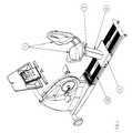
- FIG. 1is a perspective view of the exercise device of the present invention.
- FIG. 2is a perspective view of the exercise device of FIG. 1, but with the seat partially rotated.
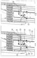
- FIG. 3is a cutaway view of the rear of the exercise device of the present invention showing the base and rolling seat platform.
- FIG. 4is a perspective view of the underside of the exercise device of the present invention showing only a cord and pulley assembly.
- FIG. 5is a perspective view of the exercise device of the present invention showing only the cord and pulley assembly together with a mounting bracket.
- FIGS. 6 a and 6 bare respective perspective views of the exercise device of the present invention showing a portion of the underside of the exercise device with a pawl in locked and unlocked positions.
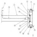
- FIG. 7is a partially broken perspective view of the rear portion of the exercise device of the present invention showing a rear cord and pulley assembly.
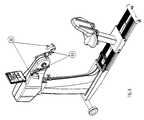
- FIG. 8is a perspective view of a further embodiment of the exercise device of the present invention.
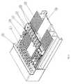
- FIG. 9is a partially broken perspective view of the base in accordance with the invention.
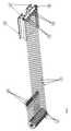
- FIG. 10is a perspective view of a portion of the base in accordance with a further embodiment of the invention, but with the hooks disengaged and the cords relaxed.
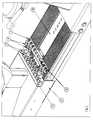
- FIG. 11is the same view as in FIG. 10, but with some of the hooks engaged and the associated cords under tension.
- the exercise device 1 of the present inventioncomprises a semi recumbent ergometer.
- the exercise device 1is configured with a plurality of pedals 2 , a controller display 3 and a magazine/water bottle holder 4 . Resistance to rotation is provided at the pedals 2 through means known to one skilled in the art, such as, via friction or via the electrotechnical resistance of an alternator.
- the exercise deviceis configured with adjustable pedal cranks 5 , such that the length of the pedal cranks 5 can be changed by altering the location of each pedal housing 6 corresponding to each of the pedal cranks 5 .
- Each of the pedal housings 6may be slid into various positions along the pedal cranks 5 and then each of the pedal housings can be locked into a preferred position.
- a seat 7is rotatably mounted to a seat pedestal 8 .
- the seat unit 7may be unlocked by pulling a locking handle 9 and rotating the seat 7 around an axis of the seat pedestal 8 .
- the seat unit 7may be locked at various positions to allow easy access for injured or disabled patients.
- the exercise deviceis configured with a base 10 that is relatively low in height. The low height of the base 10 allows a patient to easily swing his or her leg over to an opposite side.
- the seat pedestal 8is fixed to a rolling platform 11 .
- the rolling platform 11has three wheels or more 12 mounted to each of the two sides roll slide along the base 10 .
- the wheels 12run in right and left channels 13 , 14 within the base 10 .
- the wheels 12are generally constructed of molded plastic and contain ball bearings to reduce friction.
- a center wheel on each side of the rolling platform 11is mounted on an eccentric shaft (not shown) so that the rolling platform 11 can be adjusted upwards to take the play out of the rolling platform 11 .
- the base 10is preferably constructed from extruded aluminum and welded to conform to the shape of the channels 13 , 14 .
- the right channel 13is designed with a rounded portion to capture the wheels 12 on the right side of the platform 11 .
- the left channel 14is straight to allow the wheels 12 on the left side of the base 10 to float and, thereby, make up for any differences in tolerances in the assembly of the exercise device 1 .
- the rolling platform 11is locked in place using a control cable 15 and a pull pin 16 .
- the pull pin 16engages holes 17 in a seat slide rack 18 .
- the userpulls a seat release handle 19 which pulls a control cable 15 that in turn pulls the pull pin 16 out of the hole 17 it had previously been in.
- the rolling platform 11is now free to move into another position.
- a spring(not shown) within the seat lock housing 20 pushes the pull pin 16 back into the hole 17 .
- a plurality of elastic cords 21are positioned beneath the base 10 and within the frame 22 .
- Each of the elastic cords 21is configured with wrap around pulleys 23 .
- a common spindlepasses through the center of each of the pulleys 23 and is secured to side walls of the frame 22 .
- the pulleys 23may freely rotate about the spindle.
- Each of the elastic cordshave two ends, one of the ends of each elastic cord terminates on a hook 24 .
- the other end of the elastic cord 21is fixed in a slot 25 in an adjusting rack 26 .
- the diameter, design and stretch length of the elastic cords 21determine the force applied to the exercise device 1 .
- Each elastic cord 21may apply ten (10) lbs. of pressure when stretched out to its operating length.
- This forcecan be adjusted to an extent by adjusting the stretched length of the elastic cords as a group, i.e., by adjusting the position of the adjusting rack 26 .
- the adjusting rack 26contains tapped holes and jack screws 27 that are rotatably mounted to lock blocks 28 in the base 10 .
- the jack screws 27are threaded into the tapped holes in the adjustment rack 26 . It can be appreciated. that turning the jack screws 27 moves the adjusting rack 26 , thereby, adjusting the stretch of the elastic cords 21 .
- the jack screws 27may be turned to adjust the tension of the group of cords.
- hooks 24rest in receptacles in a stop block 29 that is mounted to the frame 22 .
- the stop block 29is preferably molded out of smooth plastic to prevent abrasion to the elastic cords 21 .
- the userselects the number of elastic cords 21 to use. For example, if a user opts to apply a force of fifty (50) lbs., he would select five elastic cords 21 . Because each elastic cord 21 exerts ten (10) lbs. of force, in combination, five elastic cords 21 apply fifty (50) lbs of force.
- the actual applicationis performed by the user grasping the hooks 24 and pulling them out of the stop block 29 .
- the hooks 24are then placed into slots 30 in a hook mounting bracket 31 .
- the hook mounting bracket 31is fixed to a seat slide rack 18 .
- FIG. 3shows the seat slide rack 18 has a roll free assembly in the base 10 which is comprised of a plurality of small plastic wheels 32 with ball bearings mounted to each side of the seat slide rack 18 .
- the small wheels 32run in extruded grooves 33 in the base 10 .
- the seat 7is locked to the seat slide rack 18 such that they will move synchronously.
- the seat slide rack 18only allows for a limited motion of up to about six (6) inches along the seat slide rack 18 .
- the seat slide rack 18is locked in the forward most position so it will not slide back and forth in the base 10 .
- the seat 7is adjusted so that is no longer moves upon locking the seat slide rack 18 . At this juncture, there is no load being applied to the seat 7 stemming from any elastic cord 21 via the seat slide rack 18 .
- FIGS. 6 a and 6 bthe locking mechanism of the seat slide rack 18 is demonstrated.
- a pawl 34is rotatably mounted to a lock bracket 35 via a pin 36 .
- the lock bracket 35is fixed to a section of the frame 22 not shown. It can be seen that the pawl 34 only rotates about the pin 36 .
- a slot 37 in the pawl 34engages a stud 38 that is attached to the seat slide rack 18 .
- the pawl 34is held in a locked position by an extension spring 39 .
- FIG. 6 bshows the pawl 34 in the release position.
- a seat slide rack release control cable 40is rotatably attached to the end of the pawl 34 via a shoulder bolt (not shown).
- the loadis safely applied to the seat unit 7 while pedaling the exercise device in accordance with the following method.
- a usersits on the seat unit 7 either by straddling the base 10 or by using the seat rotation feature.
- the userreleases the seat unit 7 from the seat slide rack 18 by pulling the seat release handle 19 and moves the seat to a first position for comfortable pedaling.
- the usermoves the seat 17 forward three holes 17 , each hole 17 being spaced approximately one-inch apart from the previous hole 17 (three inches) and then releases the seat release handle 19 which locks the seat unit 7 in place. Now, the user is within reaching distance of the hooks 24 that are attached to the ends of the elastic cords 21 .
- the userselects the number of hooks 24 corresponding to the desired load, in this case, five hooks 24 , and grasps the hooks 24 on the elastic cords 21 and places the hooks on the mounting bracket 31 (FIG. 5 ).
- the userplaces his/her feet on the pedals 2 , pulls the seat slide release handle 41 and pushes the seat unit 7 with the seat slide rack 18 back 3′′ to the preferred pedaling position.
- the usernow holds the load from the elastic cords 21 , which results from a tension force on the seat slide rack 18 which, in turn, exerts a second force on the seat unit 7 .
- the useris in the middle part of the seat slide rack 18 . If the user is unable to hold the load from the elastic cords 21 , the seat unit 7 will move only three inches forward or if the user pushes too hard, the seat will only move three inches backwards. In this manner, the user is safely supporting the load.
- FIG. 9is a partial cutaway view of the base.
- the seat slide rack 18is shown in its forward most position, fixed by the locking mechanism (not shown). In this position, the rear end 49 of the seat slide rack 18 rests against front rubber bumpers 46 .
- the bumpersare fixed to a front mounting bracket 45 .
- the mounting bracketis attached to the extruded base 10 . That part of the base 10 is cut away for clarity.
- the seat slide rack 18When the seat slide rack 18 is released from the locking mechanism, it can roll back supported by small plastic wheels 32 rolling in the grooves 33 in the base 10 .
- the seat slide rack 18is free to roll back until the rear end 49 it strikes the rear bumper 48 mounted in the rear stop block 47 .
- the elastic cords 21are shown extended into another position and wrapped around a second set of pulleys (not shown) under a cover 42 such that the elastic cords 21 extend out of a rear stop block and terminate on a second set of hooks 43 .
- the elastic cords 21may be attached to a rear hook mounting bracket 44 , which is fixed to the seat slide bracket 18 . In this way, loads can be applied to the seat 7 to pull it away from the pedals 2 . If heavy loads are used in this way, belts may be required on the seat to hold the user in and special pedals may also be required to secure the users feet to the pedals.
- FIG. 8another embodiment of the present invention is shown for an upper body ergometer.
- the rotating seat and rear elastic cordsoperate in the same manner as was the case for the lower body ergometer of FIGS. 1-7.
- leg pedals 2 and leg pedal cranks 5are replaced by arm pedals 60 and arm grip cranks 52 that are at a higher elevation than was the case for the leg pedals 2 and leg pedal cranks 5 .
- FIG. 10shows a partial view of the base in the area where the bungee cord hooks 24 are resting in the stop block 29 .
- the hook mounting bracket 31is replaced by the latch mounting bracket 50 .
- Thisis attached to the seat slide rack 18 .
- the latches 51are rotatably mounted to the latch mounting bracket 50 via a pivot shaft 53 .
- the latches 51have a tab 52 projecting from the free end and are injection molded plastic or other suitable material.
- FIG. 11shows the seat slide rack 18 pulled back.
- a suitable number of bungee cords 21have been attached to the latch mounting bracket 50 using the latches 52 pivoted over to engage the hooks 24 .
- a second tab 54is part of the underside of the latch. When the seat slide rack 18 is forward and locked in place, the second tabs 54 may be used to flip the latches 51 back around so they do not engage the hooks.
- stopsmay be provided that block the seat slide rack 18 from sliding relative to the base outside of a range.
- the stopsare attached to the base and bear the full load against it if the user stops exerting a force against the load applied by the elastic cords or overcomes the load with too much force.
- Metabolic work ratesare well known for standard ergometers at various mechanical work rates performed at the pedals. The pedal work measured in watts does not convert equally to calories burned or metabolic units of the user. The equations for these metabolic work rates corresponding to mechanical work rates have been long established via oxygen uptake studies on people for various types of ergometers.
- the base 10 and the frame 22may be considered as being the same component or separate components. If separate, they are attached to each other and may be treated as a unified structure.
- baserefers to either the base 10 , the frame 22 , or a composite structure in which both the base 10 and frame 22 are attached or integrally formed with each other so as to be considered the same component.
- the seat unit 7is depicted as a chair with a back rest. and a seat, the chair may be replaced by a stool or a padded post to lean against.
- the padded portion of the postmay be considered to be a seat, although the user will merely be resting their backside against it, not sitting upon it.
Landscapes
- Health & Medical Sciences (AREA)
- General Health & Medical Sciences (AREA)
- Physical Education & Sports Medicine (AREA)
- Life Sciences & Earth Sciences (AREA)
- Biophysics (AREA)
- Orthopedic Medicine & Surgery (AREA)
- Cardiology (AREA)
- Vascular Medicine (AREA)
- Seats For Vehicles (AREA)
Abstract
Description
This invention pertains to an exercise device such as a cyclocentric ergometer, but that uses elastic cords to apply force to the exercise device. The specific force applied is achieved by adjusting the length of the cords and/or by varying the number of cords that are used to exert the force. The instant invention also provides an improved method to effectively and safely vary the force exerted on an exercise device using cords.
It is known that when a patient is in the rehabilitation stage of recovering from a stroke, the patient is often too weak to stand even when being assisted. Studies have shown that training a patient to support a fractional load of one's body weight while safely seated and moving his legs in a cyclic motion is beneficial for building limb strength and for increasing limb motion coordination. Thereafter, a patient can begin to embark on assisted ambulatory efforts.
There are other key advantages to a cyclocentric ergometer, such as, toning the quadriceps muscles through constant tension load pushing towards the pedals. Pulling the patient away from the pedals causes a similar loading pattern for the hamstring muscles.
Gravity is used to create a force to apply a free rolling seat or platform to move towards or away from the pedals or arm cranks of an exercise device. This has been done by mounting the seat or platform on an inclinable track that may be set at different angles. The track uses gravity and the body weight of the user to create the force. This method, however, has limitations particularly at higher loads and steep angles.
Although, cords, specifically elastic cords, have been used to create forces for exercise equipment, such uses have been primarily directed at applying such forces to resist linear repetitions or muscle contractions similar to the manner in which weights are used in selectorized weight equipment.
What is needed is an ergometer that uses a practical system to apply force using elastic cords on the ergometer and a practical method to do this effectively and safely.
What is further needed is an ergometer in which a patient can vary the force applied by varying the length of the cord(s) and/or changing the number of cords used to apply the force.
What is also needed is an improved method for applying force to an ergometer using elastic cords.
What is also needed is an improved ergometer and, more specifically, a semi recumbent ergometer that is configured with the exercise device of the present invention.
One aspect of the invention resides in a cyclocentric ergometer and method of using it. The method includes adjusting a relative position of a seat on a seat slide rack of the cyclocentric ergometer, setting and applying a load on the seat slide rack with elastic cords that confine back and forth movement of the seat slide rack to within a range, and pedaling while sitting on the seat with the load applied.
FIG. 1 is a perspective view of the exercise device of the present invention.
FIG. 2 is a perspective view of the exercise device of FIG. 1, but with the seat partially rotated.
FIG. 3 is a cutaway view of the rear of the exercise device of the present invention showing the base and rolling seat platform.
FIG. 4 is a perspective view of the underside of the exercise device of the present invention showing only a cord and pulley assembly.
FIG. 5 is a perspective view of the exercise device of the present invention showing only the cord and pulley assembly together with a mounting bracket.
FIGS. 6aand6bare respective perspective views of the exercise device of the present invention showing a portion of the underside of the exercise device with a pawl in locked and unlocked positions.
FIG. 7 is a partially broken perspective view of the rear portion of the exercise device of the present invention showing a rear cord and pulley assembly.
FIG. 8 is a perspective view of a further embodiment of the exercise device of the present invention.
FIG. 9 is a partially broken perspective view of the base in accordance with the invention.
FIG. 10 is a perspective view of a portion of the base in accordance with a further embodiment of the invention, but with the hooks disengaged and the cords relaxed.
FIG. 11 is the same view as in FIG. 10, but with some of the hooks engaged and the associated cords under tension.
Turning to FIG. 1, theexercise device 1 of the present invention comprises a semi recumbent ergometer. In a preferred embodiment, theexercise device 1 is configured with a plurality ofpedals 2, acontroller display 3 and a magazine/water bottle holder 4. Resistance to rotation is provided at thepedals 2 through means known to one skilled in the art, such as, via friction or via the electrotechnical resistance of an alternator. In a preferred embodiment, the exercise device is configured withadjustable pedal cranks 5, such that the length of thepedal cranks 5 can be changed by altering the location of eachpedal housing 6 corresponding to each of thepedal cranks 5. Each of thepedal housings 6 may be slid into various positions along thepedal cranks 5 and then each of the pedal housings can be locked into a preferred position.
Turning to FIG. 2, aseat 7 is rotatably mounted to aseat pedestal 8. Theseat unit 7 may be unlocked by pulling alocking handle 9 and rotating theseat 7 around an axis of theseat pedestal 8. Theseat unit 7 may be locked at various positions to allow easy access for injured or disabled patients. The exercise device is configured with abase 10 that is relatively low in height. The low height of thebase 10 allows a patient to easily swing his or her leg over to an opposite side.
As shown in FIG. 3, theseat pedestal 8 is fixed to arolling platform 11. Therolling platform 11 has three wheels or more12 mounted to each of the two sides roll slide along thebase 10. Thewheels 12 run in right andleft channels base 10. Thewheels 12 are generally constructed of molded plastic and contain ball bearings to reduce friction. A center wheel on each side of therolling platform 11 is mounted on an eccentric shaft (not shown) so that therolling platform 11 can be adjusted upwards to take the play out of therolling platform 11. Thebase 10 is preferably constructed from extruded aluminum and welded to conform to the shape of thechannels right channel 13 is designed with a rounded portion to capture thewheels 12 on the right side of theplatform 11. Theleft channel 14 is straight to allow thewheels 12 on the left side of thebase 10 to float and, thereby, make up for any differences in tolerances in the assembly of theexercise device 1.
Therolling platform 11 is locked in place using acontrol cable 15 and apull pin 16. Thepull pin 16 engagesholes 17 in aseat slide rack 18. To adjust theseat 7 to a different position, the user pulls aseat release handle 19 which pulls acontrol cable 15 that in turn pulls thepull pin 16 out of thehole 17 it had previously been in. As a result, therolling platform 11 is now free to move into another position. When theseat release handle 19 is released, a spring (not shown) within theseat lock housing 20 pushes thepull pin 16 back into thehole 17.
Turning to FIG. 4, a plurality ofelastic cords 21 are positioned beneath thebase 10 and within theframe 22. Each of theelastic cords 21 is configured with wrap aroundpulleys 23. A common spindle passes through the center of each of thepulleys 23 and is secured to side walls of theframe 22. Thepulleys 23 may freely rotate about the spindle. Each of the elastic cords have two ends, one of the ends of each elastic cord terminates on ahook 24. The other end of theelastic cord 21 is fixed in aslot 25 in an adjustingrack 26. The diameter, design and stretch length of theelastic cords 21 determine the force applied to theexercise device 1. Eachelastic cord 21 may apply ten (10) lbs. of pressure when stretched out to its operating length. This force can be adjusted to an extent by adjusting the stretched length of the elastic cords as a group, i.e., by adjusting the position of theadjusting rack 26. The adjustingrack 26 contains tapped holes andjack screws 27 that are rotatably mounted to lockblocks 28 in thebase 10. The jack screws27 are threaded into the tapped holes in theadjustment rack 26. It can be appreciated. that turning the jack screws27 moves theadjusting rack 26, thereby, adjusting the stretch of theelastic cords 21. Thus, if there are differences in the tension being applied by each of theelastic cords 21, the jack screws27 may be turned to adjust the tension of the group of cords.
Turning to FIG. 5, hooks24 rest in receptacles in astop block 29 that is mounted to theframe 22. Thestop block 29 is preferably molded out of smooth plastic to prevent abrasion to theelastic cords 21. To apply a load to theseat unit 7, the user selects the number ofelastic cords 21 to use. For example, if a user opts to apply a force of fifty (50) lbs., he would select fiveelastic cords 21. Because eachelastic cord 21 exerts ten (10) lbs. of force, in combination, fiveelastic cords 21 apply fifty (50) lbs of force. The actual application is performed by the user grasping thehooks 24 and pulling them out of thestop block 29. Thehooks 24 are then placed intoslots 30 in ahook mounting bracket 31. Thehook mounting bracket 31 is fixed to aseat slide rack 18.
FIG. 3 shows theseat slide rack 18 has a roll free assembly in the base10 which is comprised of a plurality of smallplastic wheels 32 with ball bearings mounted to each side of theseat slide rack 18. Thesmall wheels 32 run inextruded grooves 33 in thebase 10. It can be seen that theseat 7 is locked to theseat slide rack 18 such that they will move synchronously. Theseat slide rack 18 only allows for a limited motion of up to about six (6) inches along theseat slide rack 18. Theseat slide rack 18 is locked in the forward most position so it will not slide back and forth in thebase 10. Theseat 7 is adjusted so that is no longer moves upon locking theseat slide rack 18. At this juncture, there is no load being applied to theseat 7 stemming from anyelastic cord 21 via theseat slide rack 18.
Turning to FIGS. 6aand6b, the locking mechanism of theseat slide rack 18 is demonstrated. Apawl 34 is rotatably mounted to alock bracket 35 via apin 36. Thelock bracket 35 is fixed to a section of theframe 22 not shown. It can be seen that thepawl 34 only rotates about thepin 36. Aslot 37 in thepawl 34 engages astud 38 that is attached to theseat slide rack 18. Thepawl 34 is held in a locked position by anextension spring 39. FIG. 6bshows thepawl 34 in the release position. A seat slide rackrelease control cable 40 is rotatably attached to the end of thepawl 34 via a shoulder bolt (not shown). In operation, when the seat slide rack release handle41 (FIG. 1) is pulled by the user, thecontrol cable 40 pulls the end of thepawl 34 so theslot 37 pulls away from thestud 38, releasing theseat slide rack 18 from theframe 22. It can be seen that theseat 7 now freely rolls with theseat slide rack 18 in proportion to the motion of theseat side rack 18.
The load is safely applied to theseat unit 7 while pedaling the exercise device in accordance with the following method. A user sits on theseat unit 7 either by straddling the base10 or by using the seat rotation feature. The user releases theseat unit 7 from theseat slide rack 18 by pulling the seat release handle19 and moves the seat to a first position for comfortable pedaling. The user moves theseat 17 forward threeholes 17, eachhole 17 being spaced approximately one-inch apart from the previous hole17 (three inches) and then releases the seat release handle19 which locks theseat unit 7 in place. Now, the user is within reaching distance of thehooks 24 that are attached to the ends of theelastic cords 21. The user then selects the number ofhooks 24 corresponding to the desired load, in this case, fivehooks 24, and grasps thehooks 24 on theelastic cords 21 and places the hooks on the mounting bracket31 (FIG.5). The user then places his/her feet on thepedals 2, pulls the seat slide release handle41 and pushes theseat unit 7 with theseat slide rack 18 back 3″ to the preferred pedaling position. The user now holds the load from theelastic cords 21, which results from a tension force on theseat slide rack 18 which, in turn, exerts a second force on theseat unit 7. The user is in the middle part of theseat slide rack 18. If the user is unable to hold the load from theelastic cords 21, theseat unit 7 will move only three inches forward or if the user pushes too hard, the seat will only move three inches backwards. In this manner, the user is safely supporting the load.
Theseat slide rack 18 is limited in it's motion by stops. FIG. 9 is a partial cutaway view of the base. Theseat slide rack 18 is shown in its forward most position, fixed by the locking mechanism (not shown). In this position, therear end 49 of theseat slide rack 18 rests againstfront rubber bumpers 46. The bumpers are fixed to a front mountingbracket 45. The mounting bracket is attached to the extrudedbase 10. That part of thebase 10 is cut away for clarity.
When theseat slide rack 18 is released from the locking mechanism, it can roll back supported by smallplastic wheels 32 rolling in thegrooves 33 in thebase 10. Theseat slide rack 18 is free to roll back until therear end 49 it strikes therear bumper 48 mounted in therear stop block 47. There is another rear bumper and rear stop block mounted in the other groove in the other side of the base not shown. It can be seen that the motion of the seat slide rack is restricted by the front and rear rubber bumpers.
Turning to FIG. 7, theelastic cords 21 are shown extended into another position and wrapped around a second set of pulleys (not shown) under acover 42 such that theelastic cords 21 extend out of a rear stop block and terminate on a second set ofhooks 43. Theelastic cords 21 may be attached to a rearhook mounting bracket 44, which is fixed to theseat slide bracket 18. In this way, loads can be applied to theseat 7 to pull it away from thepedals 2. If heavy loads are used in this way, belts may be required on the seat to hold the user in and special pedals may also be required to secure the users feet to the pedals.
Turning to FIG. 8, another embodiment of the present invention is shown for an upper body ergometer. The rotating seat and rear elastic cords operate in the same manner as was the case for the lower body ergometer of FIGS. 1-7.
The difference between the upper body ergometer and the lower body ergometer is, as best seen by comparing FIGS. 1 and 8, that theleg pedals 2 and leg pedal cranks5 are replaced by arm pedals60 and arm grip cranks52 that are at a higher elevation than was the case for theleg pedals 2 and leg pedal cranks5.
FIG. 10 shows a partial view of the base in the area where the bungee cord hooks24 are resting in thestop block 29. In this embodiment, thehook mounting bracket 31 is replaced by thelatch mounting bracket 50. This is attached to theseat slide rack 18. Thelatches 51 are rotatably mounted to thelatch mounting bracket 50 via apivot shaft 53. Thelatches 51 have atab 52 projecting from the free end and are injection molded plastic or other suitable material. When the user wants to attach a bungee cord, they place their finger or toe of their foot beneath thetab 52 and flip thelatch 51 over so it rotates around to engage thehook 24. See FIG.11. In this manner, the bungee cord hooks24 become attached to theseat slide rack 18.
FIG. 11 shows theseat slide rack 18 pulled back. A suitable number ofbungee cords 21 have been attached to thelatch mounting bracket 50 using thelatches 52 pivoted over to engage thehooks 24. Asecond tab 54 is part of the underside of the latch. When theseat slide rack 18 is forward and locked in place, thesecond tabs 54 may be used to flip thelatches 51 back around so they do not engage the hooks.
In all the embodiments, stops may be provided that block theseat slide rack 18 from sliding relative to the base outside of a range. The stops are attached to the base and bear the full load against it if the user stops exerting a force against the load applied by the elastic cords or overcomes the load with too much force.
It logically follows that the user is performing more metabolic work when pedaling an ergometer and supporting an additional steady load even if the user is not performing additional mechanical work. Metabolic work rates are well known for standard ergometers at various mechanical work rates performed at the pedals. The pedal work measured in watts does not convert equally to calories burned or metabolic units of the user. The equations for these metabolic work rates corresponding to mechanical work rates have been long established via oxygen uptake studies on people for various types of ergometers.
A study was performed to quantify and derive equations for the metabolic work rates for the various loads from the elastic cords at various mechanical pedal work rates for the Cyclocentric Semi Recumbent Ergometer. To put this into effect, the user simply has to enter the number of cords hooked to the seat into the display controller. This way the proper work rates are displayed. Another important aspect of this is when the ergometers are set to provide a constant work rate. If a set rate is desired, a portion will occur because of the elastic cord load so the mechanical work rate of the pedals can be adjusted to give the total work rate desired. This is very important in cardiac and other rehabilitation programs.
Thebase 10 and theframe 22 may be considered as being the same component or separate components. If separate, they are attached to each other and may be treated as a unified structure.
When used in the claims, the term “base” refers to either thebase 10, theframe 22, or a composite structure in which both thebase 10 andframe 22 are attached or integrally formed with each other so as to be considered the same component.
Although theseat unit 7 is depicted as a chair with a back rest. and a seat, the chair may be replaced by a stool or a padded post to lean against. The padded portion of the post may be considered to be a seat, although the user will merely be resting their backside against it, not sitting upon it.
Although the present invention has been described in relation to a particular embodiment, many other variations and modifications and other uses may become apparent to those skilled in the art.
It is preferred, therefore, that the present invention be limited not by this specific disclosure herein, but only by the appended claims.
Claims (44)
1. A method of moving a seat unit back and forth while pedaling, comprising:
adjusting the position of a seat unit and connecting the seat unit to a seat slide rack that is arranged to slide back and forth relative to a base so that the seat unit slides in unison with the seat slide rack back or forth in dependence upon a direction that a load is applied to the seat slide rack;
setting the load to be applied to the seat slide rack;
applying the load to the seat slide rack to push or pull the seat slide rack to slide back or forth depending upon the direction that the load is applied to the seat slide rack, the applying including confining an extent to which the seat slide rack may slide back or forth by using elastic cords to effect the applying of the load; and
pedaling while sitting on the seat unit and while the load is applied to the seat slide rack.
2. A method as inclaim 1 , wherein the seat unit includes a seat, a pedestal and a platform, the pedestal being arranged between the seat and the platform and being attached to the seat and the platform, the platform being slidably attached to the base to slide back and forth along the seat slide rack in response to forces of the load applied to the seat slide rack.
3. A method as inclaim 2 , wherein the connecting includes releasably locking the seat slide rack and the seat unit together so that when locked into a locking position, the seat slide rack and the seat unit are movable in unison together relative to the base and when released from the locking position, the seat slide rack and the seat unit are movable independent of each other relative to the base so a position of the seat unit can be set; and
releasably locking the seat slide rack to the base so that when the seat slide rack is locked to the base in a locked position, no relative movement may occur between the seat slide rack and the base, and when the seat slide rack is released from locked position, relative movement may occur between the seat slide rack and the base.
4. A method as inclaim 3 , further comprising:
securing the elastic cords in position to effect the setting of the load while the seat slide rack is in the locked position so that the elastic cords may exert the load on the seat slide rack when the seat slide rack is released from the locked position to confine a distance between which the seat slide rack may travel back and forth relative to the base.
5. A method as inclaim 2 , further comprising a mounting bracket, a further bracket, pulleys and a frame, the securing of the elastic cords including attaching an end of the cords to the mounting bracket while the seat slide rack is in the locked position, the mounting bracket being attached to the seat slide rack, the elastic cords being wrapped around the pulleys and being attached at a further end to the further bracket, the pulleys having respective axes that are attached to one of the base and the frame, the further bracket being attached to one of the seat slide rack, the base and the frame, the base and the frame being connected to each other.
6. A method as inclaim 5 , wherein the elastic cords are attached to the further bracket and wrapped around further pulleys whose axial centers are connected to one of the base and the frame.
7. A method as inclaim 2 , wherein the pedaling is with a pedal and crank assembly that is located at an elevation equal to or lower than that of the seat.
8. A method as inclaim 2 , wherein the pedaling is with arm grip and crank assembly that is located at an elevation higher than that of the seat.
9. A method as inclaim 5 , further comprising an adjustment mechanism that secures the further end of the elastic cords to the one of the seat slide rack and the base.
10. A method as inclaim 9 , wherein the adjustment mechanism includes a component that is fixed into one of a plurality of relative positions with respect to the base so that when the further ends of the elastic cords are attached to the further bracket, a relative position of the further ends with respect to the base is dependent upon a relative position at which the component is fixed.
11. A method as inclaim 2 , wherein the pedaling is with rotary elements mounted to a mechanism within a housing that is supported by the base.
12. A method as inclaim 2 , further comprising swiveling the seat.
13. A method as inclaim 1 , wherein the setting includes connecting a plurality of the elastic cords to a mounting bracket that is attached to the seat unit.
14. A method as inclaim 13 , further comprising tensioning the elastic cords that are connected.
15. A method as inclaim 1 , wherein the confining also includes arranging stops in a path that the seat slide rack travels to block the seat slide rack from moving past the stops.
16. A method as inclaim 13 , wherein the connecting includes pivoting latches to engage hooks at ends of the elastic cords.
17. An apparatus to move a seat unit back and forth while pedaling, comprising:
a seat slide rack that is arranged to slide back and forth relative to a base so that the seat slide rack slides back or forth in dependence upon a direction that a load is applied to the seat slide rack;
a seat unit;
means for connecting the seat unit to the seat slide rack so that the seat unit may be adjusted to a position and for then connecting the seat unit so that it is movable in unison with the seat slide rack;
means for setting the load to be applied to the seat slide rack;
means for applying the load to the seat slide rack to push or pull the seat slide rack to slide back or forth depending upon the direction that the load is applied to the seat slide rack, said means for applying including means for confining an extent to which the seat slide rack may slide back or forth, the means for confining including elastic cords arranged to apply the load to the seat slide rack; and
means for pedaling while sitting on the seat unit and while the load is applied to the seat slide rack.
18. An apparatus as inclaim 17 , wherein the seat unit includes a seat, a pedestal and a platform, the pedestal being arranged between the seat and the platform and being attached to the seat and the platform, the platform being slidably attached to the base to slide back and forth along the seat slide rack in response to forces applied to the seat slide rack.
19. An apparatus as inclaim 18 , wherein said means for connecting includes means for releasably locking the seat slide rack and the seat unit together so that when locked into a locking position, the seat slide rack and the seat unit are movable in unison together relative to the base and when released from the locking position, the seat slide rack and the seat unit are movable independent of each other relative to the base; and
means for releasably locking the seat slide rack to the base so that when the seat slide rack is locked to the base in a locked position, no relative movement may occur between the seat slide rack and the base, and when the seat slide rack is released from locked position, relative movement may occur between the seat slide rack and the base.
20. An apparatus as inclaim 19 , further comprising:
means for securing the elastic cords in position to effect the setting of the load while the seat slide rack is in the locked position so that the elastic cords may exert the load on the seat slide rack when the seat slide rack is released from the locked position to confine a distance between which the seat slide rack may travel back and forth relative to the base.
21. An apparatus as inclaim 18 , further comprising a frame, the means for securing elastic cords including means for attaching an end of the cords to a mounting bracket while the seat slide rack is in the locked position, the mounting bracket being attached to the seat slide rack, the elastic cords being wrapped around pulleys and being attached at a further end to a further bracket, the pulleys having respective axes that are attached to one of the base and the frame, the further bracket being attached to one of the seat slide rack, the base and the frame, the base and the frame being in connection with each other.
22. An apparatus as inclaim 21 , wherein the elastic cords are attached to the further bracket and wrapped around further pulleys whose axial centers are connected to one of the base and the frame.
23. An apparatus as inclaim 18 , wherein the means for pedaling includes a pedal and crank assembly that is located at an elevation equal to or lower than that of the seat.
24. An apparatus as inclaim 18 , wherein the means for pedaling includes arm grip and crank assembly that is located at an elevation higher than that of the seat.
25. An apparatus as inclaim 21 , further comprising an adjustment mechanism that is arranged to secure the further end of the elastic cords to the one of the seat slide rack and the base.
26. An apparatus as inclaim 25 , wherein the adjustment mechanism includes a component that is fixed into one of a plurality of relative positions with respect to the base so that when the further ends of the elastic cords are attached to the further bracket, a relative position of the further ends with respect to the base is dependent upon a relative position at which the component is fixed.
27. An apparatus as inclaim 26 , wherein the pedaling means includes rotary elements that are mounted to a mechanism within a housing that is attached to one of the frame and the base.
28. An apparatus as inclaim 18 , further comprising means for swiveling the seat.
29. An apparatus as inclaim 20 , further comprising latches that are pivoted to swing about a pivot to engage hooks at ends of the elastic cords.
30. An apparatus as inclaim 17 , wherein said confining means includes stops arranged in a path of the seat slide rack to block the seat slide rack from passing the stops.
31. An apparatus to move a seat unit back and forth while pedaling, comprising:
a seat unit;
a seat slide rack that is arranged to slide back and forth relative to a base in dependence upon a direction that a load is applied to the seat unit;
a connector arranged to connect the seat unit to the seat slide rack and so that the seat unit may be adjusted to a position;
a setting mechanism configured to set the load to be applied to the seat slide rack;
a load applying mechanism configured to apply the load to the seat slide rack to push or pull the seat slide rack to slide back or forth depending upon the direction that the load is applied to the seat slide rack, the load applying mechanism including a confining mechanism arranged to confine an extent to which the seat slide rack may slide and means for pedaling while sitting on the seat and while the load is applied to the seat slide rack.
32. An apparatus as inclaim 31 , wherein the seat unit includes a seat, a pedestal and a platform, the pedestal being arranged between the seat and the platform and being attached to the seat and the platform, the platform being slidably attached to the base to slide back and forth along the seat slide rack in response to forces applied to the seat slide rack.
33. An apparatus as inclaim 32 , wherein the connector includes a releasably locking mechanism arranged to releasably lock the seat slide rack and the seat unit together so that when locked into a locking position, the seat slide rack and the seat unit are movable in unison together relative to the base and when released from the locking position, the seat slide rack and the seat unit are movable independent of each other relative to the base; and
a further releasably locking mechanism arranged to releasably lock the seat slide rack to the base so that when the seat slide rack is locked to the base in a locked position, no relative movement may occur between the seat slide rack and the base, and when the seat slide rack is released from locked position, relative movement may occur between the seat slide rack and the base.
34. An apparatus as inclaim 33 , further comprising:
securing mechanism arranged to secure the elastic cords in position to effect the setting of the load while the seat slide rack is in the locked position so that the elastic cords may exert the load on the seat slide rack when the seat slide rack is released from the locked position to confine a distance between which the seat slide rack may travel back and forth relative to the base.
35. An apparatus as inclaim 34 , further comprising a mounting bracket, a further bracket, pulleys and a frame, the securing mechanism including an attaching mechanism configured to attach an end of the cords to a mounting bracket while the seat slide rack is in the locked position, the mounting bracket being attached to the seat slide rack, the elastic cords being wrapped around the pulleys and being attached at a further end to the further bracket, the pulleys having respective axes that are attached to one of the base and the frame, the further bracket being attached to one of the seat slide rack, the base and the frame, the frame and the base being connected to each other.
36. An apparatus as inclaim 35 , wherein the elastic cords are attached to the further bracket and wrapped around further pulleys whose axial centers are connected to one of the base and the frame.
37. An apparatus as inclaim 32 , wherein the means for pedaling includes a pedal and crank assembly that is located at an elevation equal to or lower than that of the seat.
38. An apparatus as inclaim 32 , wherein the means for pedaling includes arm grip and crank assembly that is located at an elevation higher than that of the seat.
39. An apparatus as inclaim 35 , further comprising an adjustment mechanism that is arranged to secure the further end of the elastic cords to the one of the seat slide rack and the base.
40. An apparatus as inclaim 39 , wherein the adjustment mechanism includes a component that is fixed into one of a plurality of relative positions with respect to the base so that when the further ends of the elastic cords are attached to the further bracket, a relative position of the further ends with respect to the base is dependent upon a relative position at which the component is fixed.
41. An apparatus as inclaim 40 , wherein the pedaling means includes rotary elements that are mounted to a mechanism within a housing that is attached to one of the frame and the base.
42. An apparatus as inclaim 32 , wherein the pedestal and the platform are configured and arranged to permit swiveling of the seat relative to the platform.
43. An apparatus as inclaim 34 , further comprising latches that are pivoted to swing about a pivot to engage hooks at ends of the elastic cords.
44. An apparatus as inclaim 31 , further comprising stops arranged in a path of the seat slide rack to block the seat slide rack from passing beyond the stops.
Priority Applications (1)
| Application Number | Priority Date | Filing Date | Title |
|---|---|---|---|
| US10/160,487US6652425B1 (en) | 2002-05-31 | 2002-05-31 | Cyclocentric ergometer |
Applications Claiming Priority (1)
| Application Number | Priority Date | Filing Date | Title |
|---|---|---|---|
| US10/160,487US6652425B1 (en) | 2002-05-31 | 2002-05-31 | Cyclocentric ergometer |
Publications (1)
| Publication Number | Publication Date |
|---|---|
| US6652425B1true US6652425B1 (en) | 2003-11-25 |
Family
ID=29583167
Family Applications (1)
| Application Number | Title | Priority Date | Filing Date |
|---|---|---|---|
| US10/160,487Expired - Fee RelatedUS6652425B1 (en) | 2002-05-31 | 2002-05-31 | Cyclocentric ergometer |
Country Status (1)
| Country | Link |
|---|---|
| US (1) | US6652425B1 (en) |
Cited By (116)
| Publication number | Priority date | Publication date | Assignee | Title |
|---|---|---|---|---|
| US20040198561A1 (en)* | 2003-01-17 | 2004-10-07 | Corbalis Kevin P. | Recumbent bicycle |
| US20090048074A1 (en)* | 2007-08-17 | 2009-02-19 | Kamins Paul | Orthopedic therapy system and device and a method of use |
| US20090124461A1 (en)* | 2007-11-08 | 2009-05-14 | Itzhak Pinto | Isokinetic exercise equipment |
| US7833135B2 (en) | 2007-06-27 | 2010-11-16 | Scott B. Radow | Stationary exercise equipment |
| US7862476B2 (en)* | 2005-12-22 | 2011-01-04 | Scott B. Radow | Exercise device |
| US20110118086A1 (en)* | 2005-12-22 | 2011-05-19 | Mr. Scott B. Radow | Exercise device |
| USD650871S1 (en)* | 2011-04-26 | 2011-12-20 | Nustep, Inc. | Recumbent stepper |
| ITRA20110013A1 (en)* | 2011-04-12 | 2012-10-13 | Technogym Spa | GINNICA MACHINE |
| US8701567B1 (en)* | 2009-09-08 | 2014-04-22 | Global Marketing Partners, Inc. | Portable exercise workstation |
| US20140121079A1 (en)* | 2011-05-20 | 2014-05-01 | The Superformers, Inc. | Exercise System with Positioning Markings |
| CN105582649A (en)* | 2014-11-17 | 2016-05-18 | 青岛瑞箭机电工程技术有限公司 | Sliding exercise bike |
| US9498667B1 (en) | 2012-10-29 | 2016-11-22 | Spx Fitness, Inc. | Exercise machine carriage handle system |
| US9597545B1 (en) | 2011-05-20 | 2017-03-21 | Lagree Technologies, Inc. | Exercise machine handle system |
| US9717945B2 (en) | 2011-05-20 | 2017-08-01 | Lagree Technologies, Inc. | Multiple position locking handle for an exercise machine |
| US10029141B2 (en) | 2012-10-29 | 2018-07-24 | Lagree Technologies, Inc. | Exercise machine handle indicia system |
| USD826349S1 (en)* | 2017-02-08 | 2018-08-21 | Woodway Usa, Inc. | Recumbent cycle with provision for upper body exercise |
| US10118073B2 (en) | 2016-04-04 | 2018-11-06 | Worldpro Group, LLC | Interactive apparatus and methods for muscle strengthening |
| US10188890B2 (en) | 2013-12-26 | 2019-01-29 | Icon Health & Fitness, Inc. | Magnetic resistance mechanism in a cable machine |
| US10213641B2 (en) | 2011-05-20 | 2019-02-26 | Lagree Technologies, Inc. | Exercise machine handle system |
| US10252109B2 (en) | 2016-05-13 | 2019-04-09 | Icon Health & Fitness, Inc. | Weight platform treadmill |
| US10258828B2 (en) | 2015-01-16 | 2019-04-16 | Icon Health & Fitness, Inc. | Controls for an exercise device |
| US10272317B2 (en) | 2016-03-18 | 2019-04-30 | Icon Health & Fitness, Inc. | Lighted pace feature in a treadmill |
| US10279212B2 (en) | 2013-03-14 | 2019-05-07 | Icon Health & Fitness, Inc. | Strength training apparatus with flywheel and related methods |
| US10293211B2 (en) | 2016-03-18 | 2019-05-21 | Icon Health & Fitness, Inc. | Coordinated weight selection |
| US10343017B2 (en) | 2016-11-01 | 2019-07-09 | Icon Health & Fitness, Inc. | Distance sensor for console positioning |
| US10376736B2 (en) | 2016-10-12 | 2019-08-13 | Icon Health & Fitness, Inc. | Cooling an exercise device during a dive motor runway condition |
| US20190255379A1 (en)* | 2016-11-18 | 2019-08-22 | Miguel Latronica | Pilates exercise system and method of use |
| US10426989B2 (en) | 2014-06-09 | 2019-10-01 | Icon Health & Fitness, Inc. | Cable system incorporated into a treadmill |
| US10433612B2 (en) | 2014-03-10 | 2019-10-08 | Icon Health & Fitness, Inc. | Pressure sensor to quantify work |
| US10441844B2 (en) | 2016-07-01 | 2019-10-15 | Icon Health & Fitness, Inc. | Cooling systems and methods for exercise equipment |
| USD863466S1 (en)* | 2019-05-02 | 2019-10-15 | Total Gym Global Corp. | Adjustable stationary cycle |
| US10471299B2 (en) | 2016-07-01 | 2019-11-12 | Icon Health & Fitness, Inc. | Systems and methods for cooling internal exercise equipment components |
| US10493321B2 (en) | 2016-10-20 | 2019-12-03 | Lagree Technologies, Inc. | Exercise machine with adjustable handles |
| US10493349B2 (en) | 2016-03-18 | 2019-12-03 | Icon Health & Fitness, Inc. | Display on exercise device |
| US10500473B2 (en) | 2016-10-10 | 2019-12-10 | Icon Health & Fitness, Inc. | Console positioning |
| US10543395B2 (en) | 2016-12-05 | 2020-01-28 | Icon Health & Fitness, Inc. | Offsetting treadmill deck weight during operation |
| US10561894B2 (en) | 2016-03-18 | 2020-02-18 | Icon Health & Fitness, Inc. | Treadmill with removable supports |
| US10610725B2 (en) | 2015-04-20 | 2020-04-07 | Crew Innovations, Llc | Apparatus and method for increased realism of training on exercise machines |
| US10625137B2 (en) | 2016-03-18 | 2020-04-21 | Icon Health & Fitness, Inc. | Coordinated displays in an exercise device |
| US10661114B2 (en) | 2016-11-01 | 2020-05-26 | Icon Health & Fitness, Inc. | Body weight lift mechanism on treadmill |
| US10702730B2 (en) | 2016-01-22 | 2020-07-07 | Lagree Technologies, Inc. | Exercise machine resistance adjustment system |
| US10729965B2 (en) | 2017-12-22 | 2020-08-04 | Icon Health & Fitness, Inc. | Audible belt guide in a treadmill |
| US20200353310A1 (en)* | 2019-05-10 | 2020-11-12 | OrthoGenesys, Inc. | System, method and apparatus for rehabilitation and exercise |
| US10835775B1 (en) | 2013-10-25 | 2020-11-17 | Lagree Technologies, Inc. | Exercise machine ergonomic handle system |
| US20200368574A1 (en)* | 2019-05-23 | 2020-11-26 | OrthoGenesys, Inc. | System, method and apparatus for rehabilitation and exercise with multi-configurable accessories |
| CN112155946A (en)* | 2020-10-15 | 2021-01-01 | 赵智利 | Recovered device of taking exercise of shank for orthopedics |
| US10953305B2 (en) | 2015-08-26 | 2021-03-23 | Icon Health & Fitness, Inc. | Strength exercise mechanisms |
| US20210322820A1 (en)* | 2020-04-15 | 2021-10-21 | Tana Burke | Mobile cycling apparatus |
| US11364419B2 (en) | 2019-02-21 | 2022-06-21 | Scott B. Radow | Exercise equipment with music synchronization |
| US11395936B1 (en) | 2015-12-16 | 2022-07-26 | Lagree Technologies, Inc. | Exercise machine carriage handle system |
| US11410768B2 (en) | 2019-10-03 | 2022-08-09 | Rom Technologies, Inc. | Method and system for implementing dynamic treatment environments based on patient information |
| US11433276B2 (en) | 2019-05-10 | 2022-09-06 | Rehab2Fit Technologies, Inc. | Method and system for using artificial intelligence to independently adjust resistance of pedals based on leg strength |
| US11451108B2 (en) | 2017-08-16 | 2022-09-20 | Ifit Inc. | Systems and methods for axial impact resistance in electric motors |
| US11446540B2 (en) | 2019-05-08 | 2022-09-20 | Lagree Technologies, Inc. | Exercise machine handle system |
| US11458354B2 (en)* | 2019-05-31 | 2022-10-04 | Rehab2Fit Technologies, Inc. | Modular exercise system |
| US11508482B2 (en) | 2019-10-03 | 2022-11-22 | Rom Technologies, Inc. | Systems and methods for remotely-enabled identification of a user infection |
| US11515028B2 (en) | 2019-10-03 | 2022-11-29 | Rom Technologies, Inc. | Method and system for using artificial intelligence and machine learning to create optimal treatment plans based on monetary value amount generated and/or patient outcome |
| US11515021B2 (en) | 2019-10-03 | 2022-11-29 | Rom Technologies, Inc. | Method and system to analytically optimize telehealth practice-based billing processes and revenue while enabling regulatory compliance |
| US11541274B2 (en)* | 2019-03-11 | 2023-01-03 | Rom Technologies, Inc. | System, method and apparatus for electrically actuated pedal for an exercise or rehabilitation machine |
| US11596829B2 (en) | 2019-03-11 | 2023-03-07 | Rom Technologies, Inc. | Control system for a rehabilitation and exercise electromechanical device |
| US20230218942A1 (en)* | 2022-01-07 | 2023-07-13 | Paul E. Hartigan, SR. | Strength-Training Apparatus for Outdoor Use with a Hitch or Gound Receiver |
| US11701548B2 (en) | 2019-10-07 | 2023-07-18 | Rom Technologies, Inc. | Computer-implemented questionnaire for orthopedic treatment |
| US11752391B2 (en) | 2019-03-11 | 2023-09-12 | Rom Technologies, Inc. | System, method and apparatus for adjustable pedal crank |
| US11756666B2 (en) | 2019-10-03 | 2023-09-12 | Rom Technologies, Inc. | Systems and methods to enable communication detection between devices and performance of a preventative action |
| US11801423B2 (en) | 2019-05-10 | 2023-10-31 | Rehab2Fit Technologies, Inc. | Method and system for using artificial intelligence to interact with a user of an exercise device during an exercise session |
| US11826613B2 (en) | 2019-10-21 | 2023-11-28 | Rom Technologies, Inc. | Persuasive motivation for orthopedic treatment |
| US11830601B2 (en) | 2019-10-03 | 2023-11-28 | Rom Technologies, Inc. | System and method for facilitating cardiac rehabilitation among eligible users |
| US11887717B2 (en) | 2019-10-03 | 2024-01-30 | Rom Technologies, Inc. | System and method for using AI, machine learning and telemedicine to perform pulmonary rehabilitation via an electromechanical machine |
| US11904207B2 (en) | 2019-05-10 | 2024-02-20 | Rehab2Fit Technologies, Inc. | Method and system for using artificial intelligence to present a user interface representing a user's progress in various domains |
| US11915815B2 (en) | 2019-10-03 | 2024-02-27 | Rom Technologies, Inc. | System and method for using artificial intelligence and machine learning and generic risk factors to improve cardiovascular health such that the need for additional cardiac interventions is mitigated |
| US11915816B2 (en) | 2019-10-03 | 2024-02-27 | Rom Technologies, Inc. | Systems and methods of using artificial intelligence and machine learning in a telemedical environment to predict user disease states |
| US11923057B2 (en) | 2019-10-03 | 2024-03-05 | Rom Technologies, Inc. | Method and system using artificial intelligence to monitor user characteristics during a telemedicine session |
| US11923065B2 (en) | 2019-10-03 | 2024-03-05 | Rom Technologies, Inc. | Systems and methods for using artificial intelligence and machine learning to detect abnormal heart rhythms of a user performing a treatment plan with an electromechanical machine |
| US11942205B2 (en) | 2019-10-03 | 2024-03-26 | Rom Technologies, Inc. | Method and system for using virtual avatars associated with medical professionals during exercise sessions |
| US11955220B2 (en) | 2019-10-03 | 2024-04-09 | Rom Technologies, Inc. | System and method for using AI/ML and telemedicine for invasive surgical treatment to determine a cardiac treatment plan that uses an electromechanical machine |
| US11950861B2 (en) | 2019-10-03 | 2024-04-09 | Rom Technologies, Inc. | Telemedicine for orthopedic treatment |
| US11955221B2 (en) | 2019-10-03 | 2024-04-09 | Rom Technologies, Inc. | System and method for using AI/ML to generate treatment plans to stimulate preferred angiogenesis |
| US11955222B2 (en) | 2019-10-03 | 2024-04-09 | Rom Technologies, Inc. | System and method for determining, based on advanced metrics of actual performance of an electromechanical machine, medical procedure eligibility in order to ascertain survivability rates and measures of quality-of-life criteria |
| US11955223B2 (en) | 2019-10-03 | 2024-04-09 | Rom Technologies, Inc. | System and method for using artificial intelligence and machine learning to provide an enhanced user interface presenting data pertaining to cardiac health, bariatric health, pulmonary health, and/or cardio-oncologic health for the purpose of performing preventative actions |
| US11955218B2 (en) | 2019-10-03 | 2024-04-09 | Rom Technologies, Inc. | System and method for use of telemedicine-enabled rehabilitative hardware and for encouraging rehabilitative compliance through patient-based virtual shared sessions with patient-enabled mutual encouragement across simulated social networks |
| US11957960B2 (en) | 2019-05-10 | 2024-04-16 | Rehab2Fit Technologies Inc. | Method and system for using artificial intelligence to adjust pedal resistance |
| US11961603B2 (en) | 2019-10-03 | 2024-04-16 | Rom Technologies, Inc. | System and method for using AI ML and telemedicine to perform bariatric rehabilitation via an electromechanical machine |
| US12020800B2 (en) | 2019-10-03 | 2024-06-25 | Rom Technologies, Inc. | System and method for using AI/ML and telemedicine to integrate rehabilitation for a plurality of comorbid conditions |
| US12020799B2 (en) | 2019-10-03 | 2024-06-25 | Rom Technologies, Inc. | Rowing machines, systems including rowing machines, and methods for using rowing machines to perform treatment plans for rehabilitation |
| US12057237B2 (en) | 2020-04-23 | 2024-08-06 | Rom Technologies, Inc. | Method and system for describing and recommending optimal treatment plans in adaptive telemedical or other contexts |
| US12062425B2 (en) | 2019-10-03 | 2024-08-13 | Rom Technologies, Inc. | System and method for implementing a cardiac rehabilitation protocol by using artificial intelligence and standardized measurements |
| US12087426B2 (en) | 2019-10-03 | 2024-09-10 | Rom Technologies, Inc. | Systems and methods for using AI ML to predict, based on data analytics or big data, an optimal number or range of rehabilitation sessions for a user |
| US12100499B2 (en) | 2020-08-06 | 2024-09-24 | Rom Technologies, Inc. | Method and system for using artificial intelligence and machine learning to create optimal treatment plans based on monetary value amount generated and/or patient outcome |
| US12096997B2 (en) | 2019-10-03 | 2024-09-24 | Rom Technologies, Inc. | Method and system for treating patients via telemedicine using sensor data from rehabilitation or exercise equipment |
| US12102878B2 (en) | 2019-05-10 | 2024-10-01 | Rehab2Fit Technologies, Inc. | Method and system for using artificial intelligence to determine a user's progress during interval training |
| US12150792B2 (en) | 2019-10-03 | 2024-11-26 | Rom Technologies, Inc. | Augmented reality placement of goniometer or other sensors |
| US12165768B2 (en) | 2019-10-03 | 2024-12-10 | Rom Technologies, Inc. | Method and system for use of telemedicine-enabled rehabilitative equipment for prediction of secondary disease |
| US12176091B2 (en) | 2019-10-03 | 2024-12-24 | Rom Technologies, Inc. | Systems and methods for using elliptical machine to perform cardiovascular rehabilitation |
| US12176089B2 (en) | 2019-10-03 | 2024-12-24 | Rom Technologies, Inc. | System and method for using AI ML and telemedicine for cardio-oncologic rehabilitation via an electromechanical machine |
| US12183447B2 (en) | 2019-10-03 | 2024-12-31 | Rom Technologies, Inc. | Method and system for creating an immersive enhanced reality-driven exercise experience for a user |
| US12191021B2 (en) | 2019-10-03 | 2025-01-07 | Rom Technologies, Inc. | System and method for use of telemedicine-enabled rehabilitative hardware and for encouragement of rehabilitative compliance through patient-based virtual shared sessions |
| US12191018B2 (en) | 2019-10-03 | 2025-01-07 | Rom Technologies, Inc. | System and method for using artificial intelligence in telemedicine-enabled hardware to optimize rehabilitative routines capable of enabling remote rehabilitative compliance |
| US12217865B2 (en) | 2019-10-03 | 2025-02-04 | Rom Technologies, Inc. | Method and system for enabling physician-smart virtual conference rooms for use in a telehealth context |
| US12220201B2 (en) | 2019-10-03 | 2025-02-11 | Rom Technologies, Inc. | Remote examination through augmented reality |
| US12224052B2 (en) | 2019-10-03 | 2025-02-11 | Rom Technologies, Inc. | System and method for using AI, machine learning and telemedicine for long-term care via an electromechanical machine |
| US12230382B2 (en) | 2019-10-03 | 2025-02-18 | Rom Technologies, Inc. | Systems and methods for using artificial intelligence and machine learning to predict a probability of an undesired medical event occurring during a treatment plan |
| US12230381B2 (en) | 2019-10-03 | 2025-02-18 | Rom Technologies, Inc. | System and method for an enhanced healthcare professional user interface displaying measurement information for a plurality of users |
| US12246222B2 (en) | 2019-10-03 | 2025-03-11 | Rom Technologies, Inc. | Method and system for using artificial intelligence to assign patients to cohorts and dynamically controlling a treatment apparatus based on the assignment during an adaptive telemedical session |
| US12249410B2 (en) | 2019-10-03 | 2025-03-11 | Rom Technologies, Inc. | System and method for use of treatment device to reduce pain medication dependency |
| US12283356B2 (en) | 2019-10-03 | 2025-04-22 | Rom Technologies, Inc. | System and method for processing medical claims using biometric signatures |
| US12301663B2 (en) | 2019-10-03 | 2025-05-13 | Rom Technologies, Inc. | System and method for transmitting data and ordering asynchronous data |
| US12327623B2 (en) | 2019-10-03 | 2025-06-10 | Rom Technologies, Inc. | System and method for processing medical claims |
| US12347558B2 (en) | 2019-10-03 | 2025-07-01 | Rom Technologies, Inc. | Method and system for using artificial intelligence and machine learning to provide recommendations to a healthcare provider in or near real-time during a telemedicine session |
| US12347543B2 (en) | 2019-10-03 | 2025-07-01 | Rom Technologies, Inc. | Systems and methods for using artificial intelligence to implement a cardio protocol via a relay-based system |
| US12357195B2 (en) | 2020-06-26 | 2025-07-15 | Rom Technologies, Inc. | System, method and apparatus for anchoring an electronic device and measuring a joint angle |
| US12380984B2 (en) | 2019-10-03 | 2025-08-05 | Rom Technologies, Inc. | Systems and methods for using artificial intelligence and machine learning to generate treatment plans having dynamically tailored cardiac protocols for users to manage a state of an electromechanical machine |
| US12402805B2 (en) | 2019-09-17 | 2025-09-02 | Rom Technologies, Inc. | Wearable device for coupling to a user, and measuring and monitoring user activity |
| US12420145B2 (en) | 2019-10-03 | 2025-09-23 | Rom Technologies, Inc. | Systems and methods of using artificial intelligence and machine learning for generating alignment plans to align a user with an imaging sensor during a treatment session |
| US12420143B1 (en) | 2019-10-03 | 2025-09-23 | Rom Technologies, Inc. | System and method for enabling residentially-based cardiac rehabilitation by using an electromechanical machine and educational content to mitigate risk factors and optimize user behavior |
| US12424319B2 (en) | 2019-11-06 | 2025-09-23 | Rom Technologies, Inc. | System for remote treatment utilizing privacy controls |
| US12427376B2 (en) | 2019-10-03 | 2025-09-30 | Rom Technologies, Inc. | Systems and methods for an artificial intelligence engine to optimize a peak performance |
Citations (3)
| Publication number | Priority date | Publication date | Assignee | Title |
|---|---|---|---|---|
| US4798378A (en)* | 1985-07-15 | 1989-01-17 | Jones Robert S | Rowing machine |
| US5732964A (en)* | 1995-04-27 | 1998-03-31 | Magic Walker, L.C. | User-propelled steerable apparatus |
| US6238322B1 (en)* | 1999-08-18 | 2001-05-29 | Hank Hsu | Exercise machine having a sliding seat selectively coupled to a sliding damping member |
- 2002
- 2002-05-31USUS10/160,487patent/US6652425B1/ennot_activeExpired - Fee Related
Patent Citations (3)
| Publication number | Priority date | Publication date | Assignee | Title |
|---|---|---|---|---|
| US4798378A (en)* | 1985-07-15 | 1989-01-17 | Jones Robert S | Rowing machine |
| US5732964A (en)* | 1995-04-27 | 1998-03-31 | Magic Walker, L.C. | User-propelled steerable apparatus |
| US6238322B1 (en)* | 1999-08-18 | 2001-05-29 | Hank Hsu | Exercise machine having a sliding seat selectively coupled to a sliding damping member |
Cited By (166)
| Publication number | Priority date | Publication date | Assignee | Title |
|---|---|---|---|---|
| US7736281B2 (en) | 2003-01-17 | 2010-06-15 | Unisen, Inc. | Recumbent bicycle |
| EP1583589A4 (en)* | 2003-01-17 | 2008-11-26 | Unisen Inc | Recumbent bicycle |
| US20040198561A1 (en)* | 2003-01-17 | 2004-10-07 | Corbalis Kevin P. | Recumbent bicycle |
| US20110006566A1 (en)* | 2003-01-17 | 2011-01-13 | Unisen, Inc., Dba Star Trac | Recumbent bicycle |
| US7976434B2 (en)* | 2005-12-22 | 2011-07-12 | Scott B. Radow | Exercise device |
| US7862476B2 (en)* | 2005-12-22 | 2011-01-04 | Scott B. Radow | Exercise device |
| US20110118086A1 (en)* | 2005-12-22 | 2011-05-19 | Mr. Scott B. Radow | Exercise device |
| US7833135B2 (en) | 2007-06-27 | 2010-11-16 | Scott B. Radow | Stationary exercise equipment |
| US8348811B2 (en)* | 2007-08-17 | 2013-01-08 | Kamins Paul | Orthopedic therapy system and device and a method of use |
| US20090048074A1 (en)* | 2007-08-17 | 2009-02-19 | Kamins Paul | Orthopedic therapy system and device and a method of use |
| US20090124461A1 (en)* | 2007-11-08 | 2009-05-14 | Itzhak Pinto | Isokinetic exercise equipment |
| US7717824B2 (en)* | 2007-11-08 | 2010-05-18 | Itzhak Pinto | Isokinetic exercise equipment |
| US8701567B1 (en)* | 2009-09-08 | 2014-04-22 | Global Marketing Partners, Inc. | Portable exercise workstation |
| ITRA20110013A1 (en)* | 2011-04-12 | 2012-10-13 | Technogym Spa | GINNICA MACHINE |
| USD650871S1 (en)* | 2011-04-26 | 2011-12-20 | Nustep, Inc. | Recumbent stepper |
| US20140121079A1 (en)* | 2011-05-20 | 2014-05-01 | The Superformers, Inc. | Exercise System with Positioning Markings |
| US9717945B2 (en) | 2011-05-20 | 2017-08-01 | Lagree Technologies, Inc. | Multiple position locking handle for an exercise machine |
| US10213641B2 (en) | 2011-05-20 | 2019-02-26 | Lagree Technologies, Inc. | Exercise machine handle system |
| US20170043210A9 (en)* | 2011-05-20 | 2017-02-16 | The Superformers, Inc. | Exercise System with Positioning Markings |
| US9597545B1 (en) | 2011-05-20 | 2017-03-21 | Lagree Technologies, Inc. | Exercise machine handle system |
| US10029141B2 (en) | 2012-10-29 | 2018-07-24 | Lagree Technologies, Inc. | Exercise machine handle indicia system |
| US10716964B1 (en) | 2012-10-29 | 2020-07-21 | Lagree Technologies, Inc. | Exercise machine carriage handle system |
| US10118067B2 (en) | 2012-10-29 | 2018-11-06 | Lagree Technologies, Inc. | Exercise machine carriage handle system |
| US9604095B1 (en) | 2012-10-29 | 2017-03-28 | Lagree Technologies, Inc. | Exercise machine carriage handle system |
| US9498667B1 (en) | 2012-10-29 | 2016-11-22 | Spx Fitness, Inc. | Exercise machine carriage handle system |
| US10220244B2 (en) | 2012-10-29 | 2019-03-05 | Lagree Technologies, Inc. | Exercise machine handle indicia system |
| US10279212B2 (en) | 2013-03-14 | 2019-05-07 | Icon Health & Fitness, Inc. | Strength training apparatus with flywheel and related methods |
| US11759671B2 (en) | 2013-10-23 | 2023-09-19 | Lagree Technologies, Inc. | Exercise machine handle system |
| US10744370B1 (en) | 2013-10-23 | 2020-08-18 | Lagree Technologies, Inc. | Exercise machine handle system |
| US11148004B1 (en) | 2013-10-23 | 2021-10-19 | Lagree Technologies, Inc. | Exercise machine handle system |
| US11020627B1 (en) | 2013-10-25 | 2021-06-01 | Lagree Technologies, Inc. | Exercise machine ergonomic handle system |
| US10835775B1 (en) | 2013-10-25 | 2020-11-17 | Lagree Technologies, Inc. | Exercise machine ergonomic handle system |
| US10926127B1 (en) | 2013-10-25 | 2021-02-23 | Lagree Technologies, Inc. | Exercise machine ergonomic handle system |
| US10188890B2 (en) | 2013-12-26 | 2019-01-29 | Icon Health & Fitness, Inc. | Magnetic resistance mechanism in a cable machine |
| US10433612B2 (en) | 2014-03-10 | 2019-10-08 | Icon Health & Fitness, Inc. | Pressure sensor to quantify work |
| US10426989B2 (en) | 2014-06-09 | 2019-10-01 | Icon Health & Fitness, Inc. | Cable system incorporated into a treadmill |
| CN105582649A (en)* | 2014-11-17 | 2016-05-18 | 青岛瑞箭机电工程技术有限公司 | Sliding exercise bike |
| US10258828B2 (en) | 2015-01-16 | 2019-04-16 | Icon Health & Fitness, Inc. | Controls for an exercise device |
| US10610725B2 (en) | 2015-04-20 | 2020-04-07 | Crew Innovations, Llc | Apparatus and method for increased realism of training on exercise machines |
| US10953305B2 (en) | 2015-08-26 | 2021-03-23 | Icon Health & Fitness, Inc. | Strength exercise mechanisms |
| US11826605B2 (en) | 2015-12-16 | 2023-11-28 | Lagree Technologies, Inc. | Exercise machine carriage handle system |
| US11395936B1 (en) | 2015-12-16 | 2022-07-26 | Lagree Technologies, Inc. | Exercise machine carriage handle system |
| US11161001B1 (en) | 2016-01-22 | 2021-11-02 | Lagree Technologies, Inc. | Exercise machine resistance adjustment system |
| US11839786B2 (en) | 2016-01-22 | 2023-12-12 | Lagree Technologies, Inc. | Exercise machine resistance adjustment system |
| US11524197B2 (en) | 2016-01-22 | 2022-12-13 | Lagree Technologies, Inc. | Exercise machine resistance adjustment system |
| US10702730B2 (en) | 2016-01-22 | 2020-07-07 | Lagree Technologies, Inc. | Exercise machine resistance adjustment system |
| US10625137B2 (en) | 2016-03-18 | 2020-04-21 | Icon Health & Fitness, Inc. | Coordinated displays in an exercise device |
| US10272317B2 (en) | 2016-03-18 | 2019-04-30 | Icon Health & Fitness, Inc. | Lighted pace feature in a treadmill |
| US10293211B2 (en) | 2016-03-18 | 2019-05-21 | Icon Health & Fitness, Inc. | Coordinated weight selection |
| US10561894B2 (en) | 2016-03-18 | 2020-02-18 | Icon Health & Fitness, Inc. | Treadmill with removable supports |
| US10493349B2 (en) | 2016-03-18 | 2019-12-03 | Icon Health & Fitness, Inc. | Display on exercise device |
| US10850162B2 (en) | 2016-04-04 | 2020-12-01 | Worldpro Group, L.L.C. | Interactive apparatus and methods for muscle strengthening |
| US10118073B2 (en) | 2016-04-04 | 2018-11-06 | Worldpro Group, LLC | Interactive apparatus and methods for muscle strengthening |
| US10252109B2 (en) | 2016-05-13 | 2019-04-09 | Icon Health & Fitness, Inc. | Weight platform treadmill |
| US10441844B2 (en) | 2016-07-01 | 2019-10-15 | Icon Health & Fitness, Inc. | Cooling systems and methods for exercise equipment |
| US10471299B2 (en) | 2016-07-01 | 2019-11-12 | Icon Health & Fitness, Inc. | Systems and methods for cooling internal exercise equipment components |
| US10500473B2 (en) | 2016-10-10 | 2019-12-10 | Icon Health & Fitness, Inc. | Console positioning |
| US10376736B2 (en) | 2016-10-12 | 2019-08-13 | Icon Health & Fitness, Inc. | Cooling an exercise device during a dive motor runway condition |
| US11154749B1 (en) | 2016-10-20 | 2021-10-26 | Lagree Technologies, Inc. | Exercise machine with adjustable handles |
| US11980789B2 (en) | 2016-10-20 | 2024-05-14 | Lagree Technologies, Inc. | Exercise machine with adjustable handles |
| US10493321B2 (en) | 2016-10-20 | 2019-12-03 | Lagree Technologies, Inc. | Exercise machine with adjustable handles |
| US11565151B2 (en) | 2016-10-20 | 2023-01-31 | Lagree Technologies, Inc. | Exercise machine with adjustable handles |
| US12246216B2 (en) | 2016-10-20 | 2025-03-11 | Lagree Technologies, Inc. | Exercise machine with adjustable handles |
| US10661114B2 (en) | 2016-11-01 | 2020-05-26 | Icon Health & Fitness, Inc. | Body weight lift mechanism on treadmill |
| US10343017B2 (en) | 2016-11-01 | 2019-07-09 | Icon Health & Fitness, Inc. | Distance sensor for console positioning |
| US10556146B2 (en)* | 2016-11-18 | 2020-02-11 | Miguel Latronica | Pilates exercise system and method of use |
| US20190255379A1 (en)* | 2016-11-18 | 2019-08-22 | Miguel Latronica | Pilates exercise system and method of use |
| US10543395B2 (en) | 2016-12-05 | 2020-01-28 | Icon Health & Fitness, Inc. | Offsetting treadmill deck weight during operation |
| USD826349S1 (en)* | 2017-02-08 | 2018-08-21 | Woodway Usa, Inc. | Recumbent cycle with provision for upper body exercise |
| US11451108B2 (en) | 2017-08-16 | 2022-09-20 | Ifit Inc. | Systems and methods for axial impact resistance in electric motors |
| US10729965B2 (en) | 2017-12-22 | 2020-08-04 | Icon Health & Fitness, Inc. | Audible belt guide in a treadmill |
| US11364419B2 (en) | 2019-02-21 | 2022-06-21 | Scott B. Radow | Exercise equipment with music synchronization |
| US12226671B2 (en) | 2019-03-11 | 2025-02-18 | Rom Technologies, Inc. | System, method and apparatus for electrically actuated pedal for an exercise or rehabilitation machine |
| US12059591B2 (en) | 2019-03-11 | 2024-08-13 | Rom Technologies, Inc. | Bendable sensor device for monitoring joint extension and flexion |
| US12029940B2 (en) | 2019-03-11 | 2024-07-09 | Rom Technologies, Inc. | Single sensor wearable device for monitoring joint extension and flexion |
| US12226670B2 (en) | 2019-03-11 | 2025-02-18 | Rom Technologies, Inc. | System, method and apparatus for electrically actuated pedal for an exercise or rehabilitation machine |
| US12083380B2 (en) | 2019-03-11 | 2024-09-10 | Rom Technologies, Inc. | Bendable sensor device for monitoring joint extension and flexion |
| US11752391B2 (en) | 2019-03-11 | 2023-09-12 | Rom Technologies, Inc. | System, method and apparatus for adjustable pedal crank |
| US11541274B2 (en)* | 2019-03-11 | 2023-01-03 | Rom Technologies, Inc. | System, method and apparatus for electrically actuated pedal for an exercise or rehabilitation machine |
| US12083381B2 (en) | 2019-03-11 | 2024-09-10 | Rom Technologies, Inc. | Bendable sensor device for monitoring joint extension and flexion |
| US11596829B2 (en) | 2019-03-11 | 2023-03-07 | Rom Technologies, Inc. | Control system for a rehabilitation and exercise electromechanical device |
| US12186623B2 (en) | 2019-03-11 | 2025-01-07 | Rom Technologies, Inc. | Monitoring joint extension and flexion using a sensor device securable to an upper and lower limb |
| US11904202B2 (en) | 2019-03-11 | 2024-02-20 | Rom Technolgies, Inc. | Monitoring joint extension and flexion using a sensor device securable to an upper and lower limb |
| USD863466S1 (en)* | 2019-05-02 | 2019-10-15 | Total Gym Global Corp. | Adjustable stationary cycle |
| US11446540B2 (en) | 2019-05-08 | 2022-09-20 | Lagree Technologies, Inc. | Exercise machine handle system |
| US12121767B2 (en) | 2019-05-08 | 2024-10-22 | Lagree Technologies, Inc. | Exercise machine handle system |
| US11684818B2 (en) | 2019-05-08 | 2023-06-27 | Lagree Technologies, Inc. | Exercise machine handle system |
| US20200353310A1 (en)* | 2019-05-10 | 2020-11-12 | OrthoGenesys, Inc. | System, method and apparatus for rehabilitation and exercise |
| US11801423B2 (en) | 2019-05-10 | 2023-10-31 | Rehab2Fit Technologies, Inc. | Method and system for using artificial intelligence to interact with a user of an exercise device during an exercise session |
| US12102878B2 (en) | 2019-05-10 | 2024-10-01 | Rehab2Fit Technologies, Inc. | Method and system for using artificial intelligence to determine a user's progress during interval training |
| US11957956B2 (en)* | 2019-05-10 | 2024-04-16 | Rehab2Fit Technologies, Inc. | System, method and apparatus for rehabilitation and exercise |
| US11433276B2 (en) | 2019-05-10 | 2022-09-06 | Rehab2Fit Technologies, Inc. | Method and system for using artificial intelligence to independently adjust resistance of pedals based on leg strength |
| US12285654B2 (en) | 2019-05-10 | 2025-04-29 | Rom Technologies, Inc. | Method and system for using artificial intelligence to interact with a user of an exercise device during an exercise session |
| US12324961B2 (en) | 2019-05-10 | 2025-06-10 | Rom Technologies, Inc. | Method and system for using artificial intelligence to present a user interface representing a user's progress in various domains |
| US11957960B2 (en) | 2019-05-10 | 2024-04-16 | Rehab2Fit Technologies Inc. | Method and system for using artificial intelligence to adjust pedal resistance |
| US11904207B2 (en) | 2019-05-10 | 2024-02-20 | Rehab2Fit Technologies, Inc. | Method and system for using artificial intelligence to present a user interface representing a user's progress in various domains |
| US11801419B2 (en)* | 2019-05-23 | 2023-10-31 | Rehab2Fit Technologies, Inc. | System, method and apparatus for rehabilitation and exercise with multi-configurable accessories |
| US20200368574A1 (en)* | 2019-05-23 | 2020-11-26 | OrthoGenesys, Inc. | System, method and apparatus for rehabilitation and exercise with multi-configurable accessories |
| US11458354B2 (en)* | 2019-05-31 | 2022-10-04 | Rehab2Fit Technologies, Inc. | Modular exercise system |
| US12402805B2 (en) | 2019-09-17 | 2025-09-02 | Rom Technologies, Inc. | Wearable device for coupling to a user, and measuring and monitoring user activity |
| US12096997B2 (en) | 2019-10-03 | 2024-09-24 | Rom Technologies, Inc. | Method and system for treating patients via telemedicine using sensor data from rehabilitation or exercise equipment |
| US12191021B2 (en) | 2019-10-03 | 2025-01-07 | Rom Technologies, Inc. | System and method for use of telemedicine-enabled rehabilitative hardware and for encouragement of rehabilitative compliance through patient-based virtual shared sessions |
| US11942205B2 (en) | 2019-10-03 | 2024-03-26 | Rom Technologies, Inc. | Method and system for using virtual avatars associated with medical professionals during exercise sessions |
| US11955220B2 (en) | 2019-10-03 | 2024-04-09 | Rom Technologies, Inc. | System and method for using AI/ML and telemedicine for invasive surgical treatment to determine a cardiac treatment plan that uses an electromechanical machine |
| US11950861B2 (en) | 2019-10-03 | 2024-04-09 | Rom Technologies, Inc. | Telemedicine for orthopedic treatment |
| US11955221B2 (en) | 2019-10-03 | 2024-04-09 | Rom Technologies, Inc. | System and method for using AI/ML to generate treatment plans to stimulate preferred angiogenesis |
| US11955222B2 (en) | 2019-10-03 | 2024-04-09 | Rom Technologies, Inc. | System and method for determining, based on advanced metrics of actual performance of an electromechanical machine, medical procedure eligibility in order to ascertain survivability rates and measures of quality-of-life criteria |
| US11955223B2 (en) | 2019-10-03 | 2024-04-09 | Rom Technologies, Inc. | System and method for using artificial intelligence and machine learning to provide an enhanced user interface presenting data pertaining to cardiac health, bariatric health, pulmonary health, and/or cardio-oncologic health for the purpose of performing preventative actions |
| US11955218B2 (en) | 2019-10-03 | 2024-04-09 | Rom Technologies, Inc. | System and method for use of telemedicine-enabled rehabilitative hardware and for encouraging rehabilitative compliance through patient-based virtual shared sessions with patient-enabled mutual encouragement across simulated social networks |
| US11923065B2 (en) | 2019-10-03 | 2024-03-05 | Rom Technologies, Inc. | Systems and methods for using artificial intelligence and machine learning to detect abnormal heart rhythms of a user performing a treatment plan with an electromechanical machine |
| US11961603B2 (en) | 2019-10-03 | 2024-04-16 | Rom Technologies, Inc. | System and method for using AI ML and telemedicine to perform bariatric rehabilitation via an electromechanical machine |
| US11923057B2 (en) | 2019-10-03 | 2024-03-05 | Rom Technologies, Inc. | Method and system using artificial intelligence to monitor user characteristics during a telemedicine session |
| US11978559B2 (en) | 2019-10-03 | 2024-05-07 | Rom Technologies, Inc. | Systems and methods for remotely-enabled identification of a user infection |
| US11915816B2 (en) | 2019-10-03 | 2024-02-27 | Rom Technologies, Inc. | Systems and methods of using artificial intelligence and machine learning in a telemedical environment to predict user disease states |
| US12020800B2 (en) | 2019-10-03 | 2024-06-25 | Rom Technologies, Inc. | System and method for using AI/ML and telemedicine to integrate rehabilitation for a plurality of comorbid conditions |
| US12020799B2 (en) | 2019-10-03 | 2024-06-25 | Rom Technologies, Inc. | Rowing machines, systems including rowing machines, and methods for using rowing machines to perform treatment plans for rehabilitation |
| US11915815B2 (en) | 2019-10-03 | 2024-02-27 | Rom Technologies, Inc. | System and method for using artificial intelligence and machine learning and generic risk factors to improve cardiovascular health such that the need for additional cardiac interventions is mitigated |
| US12427376B2 (en) | 2019-10-03 | 2025-09-30 | Rom Technologies, Inc. | Systems and methods for an artificial intelligence engine to optimize a peak performance |
| US11887717B2 (en) | 2019-10-03 | 2024-01-30 | Rom Technologies, Inc. | System and method for using AI, machine learning and telemedicine to perform pulmonary rehabilitation via an electromechanical machine |
| US12062425B2 (en) | 2019-10-03 | 2024-08-13 | Rom Technologies, Inc. | System and method for implementing a cardiac rehabilitation protocol by using artificial intelligence and standardized measurements |
| US12087426B2 (en) | 2019-10-03 | 2024-09-10 | Rom Technologies, Inc. | Systems and methods for using AI ML to predict, based on data analytics or big data, an optimal number or range of rehabilitation sessions for a user |
| US12420143B1 (en) | 2019-10-03 | 2025-09-23 | Rom Technologies, Inc. | System and method for enabling residentially-based cardiac rehabilitation by using an electromechanical machine and educational content to mitigate risk factors and optimize user behavior |
| US11830601B2 (en) | 2019-10-03 | 2023-11-28 | Rom Technologies, Inc. | System and method for facilitating cardiac rehabilitation among eligible users |
| US12420145B2 (en) | 2019-10-03 | 2025-09-23 | Rom Technologies, Inc. | Systems and methods of using artificial intelligence and machine learning for generating alignment plans to align a user with an imaging sensor during a treatment session |
| US12380984B2 (en) | 2019-10-03 | 2025-08-05 | Rom Technologies, Inc. | Systems and methods for using artificial intelligence and machine learning to generate treatment plans having dynamically tailored cardiac protocols for users to manage a state of an electromechanical machine |
| US11756666B2 (en) | 2019-10-03 | 2023-09-12 | Rom Technologies, Inc. | Systems and methods to enable communication detection between devices and performance of a preventative action |
| US12380985B2 (en) | 2019-10-03 | 2025-08-05 | Rom Technologies, Inc. | Method and system for implementing dynamic treatment environments based on patient information |
| US12154672B2 (en) | 2019-10-03 | 2024-11-26 | Rom Technologies, Inc. | Method and system for implementing dynamic treatment environments based on patient information |
| US12150792B2 (en) | 2019-10-03 | 2024-11-26 | Rom Technologies, Inc. | Augmented reality placement of goniometer or other sensors |
| US12165768B2 (en) | 2019-10-03 | 2024-12-10 | Rom Technologies, Inc. | Method and system for use of telemedicine-enabled rehabilitative equipment for prediction of secondary disease |
| US12176091B2 (en) | 2019-10-03 | 2024-12-24 | Rom Technologies, Inc. | Systems and methods for using elliptical machine to perform cardiovascular rehabilitation |
| US12176089B2 (en) | 2019-10-03 | 2024-12-24 | Rom Technologies, Inc. | System and method for using AI ML and telemedicine for cardio-oncologic rehabilitation via an electromechanical machine |
| US12183447B2 (en) | 2019-10-03 | 2024-12-31 | Rom Technologies, Inc. | Method and system for creating an immersive enhanced reality-driven exercise experience for a user |
| US12347543B2 (en) | 2019-10-03 | 2025-07-01 | Rom Technologies, Inc. | Systems and methods for using artificial intelligence to implement a cardio protocol via a relay-based system |
| US12343180B2 (en) | 2019-10-03 | 2025-07-01 | Rom Technologies, Inc. | Augmented reality placement of goniometer or other sensors |
| US12191018B2 (en) | 2019-10-03 | 2025-01-07 | Rom Technologies, Inc. | System and method for using artificial intelligence in telemedicine-enabled hardware to optimize rehabilitative routines capable of enabling remote rehabilitative compliance |
| US12217865B2 (en) | 2019-10-03 | 2025-02-04 | Rom Technologies, Inc. | Method and system for enabling physician-smart virtual conference rooms for use in a telehealth context |
| US12220201B2 (en) | 2019-10-03 | 2025-02-11 | Rom Technologies, Inc. | Remote examination through augmented reality |
| US12220202B2 (en) | 2019-10-03 | 2025-02-11 | Rom Technologies, Inc. | Remote examination through augmented reality |
| US12224052B2 (en) | 2019-10-03 | 2025-02-11 | Rom Technologies, Inc. | System and method for using AI, machine learning and telemedicine for long-term care via an electromechanical machine |
| US11515021B2 (en) | 2019-10-03 | 2022-11-29 | Rom Technologies, Inc. | Method and system to analytically optimize telehealth practice-based billing processes and revenue while enabling regulatory compliance |
| US12230383B2 (en) | 2019-10-03 | 2025-02-18 | Rom Technologies, Inc. | United states systems and methods for using elliptical machine to perform cardiovascular rehabilitation |
| US12230382B2 (en) | 2019-10-03 | 2025-02-18 | Rom Technologies, Inc. | Systems and methods for using artificial intelligence and machine learning to predict a probability of an undesired medical event occurring during a treatment plan |
| US12230381B2 (en) | 2019-10-03 | 2025-02-18 | Rom Technologies, Inc. | System and method for an enhanced healthcare professional user interface displaying measurement information for a plurality of users |
| US11515028B2 (en) | 2019-10-03 | 2022-11-29 | Rom Technologies, Inc. | Method and system for using artificial intelligence and machine learning to create optimal treatment plans based on monetary value amount generated and/or patient outcome |
| US12246222B2 (en) | 2019-10-03 | 2025-03-11 | Rom Technologies, Inc. | Method and system for using artificial intelligence to assign patients to cohorts and dynamically controlling a treatment apparatus based on the assignment during an adaptive telemedical session |
| US11508482B2 (en) | 2019-10-03 | 2022-11-22 | Rom Technologies, Inc. | Systems and methods for remotely-enabled identification of a user infection |
| US12249410B2 (en) | 2019-10-03 | 2025-03-11 | Rom Technologies, Inc. | System and method for use of treatment device to reduce pain medication dependency |
| US12283356B2 (en) | 2019-10-03 | 2025-04-22 | Rom Technologies, Inc. | System and method for processing medical claims using biometric signatures |
| US11410768B2 (en) | 2019-10-03 | 2022-08-09 | Rom Technologies, Inc. | Method and system for implementing dynamic treatment environments based on patient information |
| US12301663B2 (en) | 2019-10-03 | 2025-05-13 | Rom Technologies, Inc. | System and method for transmitting data and ordering asynchronous data |
| US12327623B2 (en) | 2019-10-03 | 2025-06-10 | Rom Technologies, Inc. | System and method for processing medical claims |
| US12347558B2 (en) | 2019-10-03 | 2025-07-01 | Rom Technologies, Inc. | Method and system for using artificial intelligence and machine learning to provide recommendations to a healthcare provider in or near real-time during a telemedicine session |
| US12340884B2 (en) | 2019-10-03 | 2025-06-24 | Rom Technologies, Inc. | Method and system to analytically optimize telehealth practice-based billing processes and revenue while enabling regulatory compliance |
| US11701548B2 (en) | 2019-10-07 | 2023-07-18 | Rom Technologies, Inc. | Computer-implemented questionnaire for orthopedic treatment |
| US11826613B2 (en) | 2019-10-21 | 2023-11-28 | Rom Technologies, Inc. | Persuasive motivation for orthopedic treatment |
| US12390689B2 (en) | 2019-10-21 | 2025-08-19 | Rom Technologies, Inc. | Persuasive motivation for orthopedic treatment |
| US12424319B2 (en) | 2019-11-06 | 2025-09-23 | Rom Technologies, Inc. | System for remote treatment utilizing privacy controls |
| US20210322820A1 (en)* | 2020-04-15 | 2021-10-21 | Tana Burke | Mobile cycling apparatus |
| US11925834B2 (en)* | 2020-04-15 | 2024-03-12 | Tana Burke | Mobile cycling apparatus |
| US12057237B2 (en) | 2020-04-23 | 2024-08-06 | Rom Technologies, Inc. | Method and system for describing and recommending optimal treatment plans in adaptive telemedical or other contexts |
| US12357195B2 (en) | 2020-06-26 | 2025-07-15 | Rom Technologies, Inc. | System, method and apparatus for anchoring an electronic device and measuring a joint angle |
| US12100499B2 (en) | 2020-08-06 | 2024-09-24 | Rom Technologies, Inc. | Method and system for using artificial intelligence and machine learning to create optimal treatment plans based on monetary value amount generated and/or patient outcome |
| CN112155946A (en)* | 2020-10-15 | 2021-01-01 | 赵智利 | Recovered device of taking exercise of shank for orthopedics |
| US20230218942A1 (en)* | 2022-01-07 | 2023-07-13 | Paul E. Hartigan, SR. | Strength-Training Apparatus for Outdoor Use with a Hitch or Gound Receiver |
| US11857824B2 (en)* | 2022-01-07 | 2024-01-02 | Paul E Hartigan, Sr. | Strength-training apparatus for outdoor use with a hitch or ground receiver |
Similar Documents
| Publication | Publication Date | Title |
|---|---|---|
| US6652425B1 (en) | Cyclocentric ergometer | |
| US5226866A (en) | Trimodal exercise apparatus | |
| US4813667A (en) | Multipurpose exerciser | |
| US6764431B2 (en) | Swim machine | |
| US5108093A (en) | Multipurpose exerciser | |
| US7998042B2 (en) | Exercise system using exercise resistance cables | |
| US7775949B2 (en) | Shoulder stretcher assembly | |
| US5039088A (en) | Exercise machine | |
| US8870726B2 (en) | System and method for exercising | |
| US20050054492A1 (en) | Exercise device for under a desk | |
| US20110294633A1 (en) | Exercise apparatus | |
| CN210409377U (en) | Fixed bicycle type exercising apparatus | |
| CN110465045B (en) | Four-controllable gas spring structure adjusting handrail double-mode running machine | |
| WO2005081899A2 (en) | Exercise system using exercise resistance cables | |
| US20070129219A1 (en) | Exercise device | |
| WO2015138279A1 (en) | Multi-functional exercise machine | |
| US4900014A (en) | Convertible exercise cycle | |
| US20110300997A1 (en) | Exercise Apparatus | |
| US10493319B2 (en) | Exercise equipment for limited mobility individuals | |
| US6733429B2 (en) | Multi-mode exerciser | |
| JPH08266683A (en) | Exerciser | |
| US5902218A (en) | Multi-functional adjustable rotating resistance exerciser system | |
| CN114191779B (en) | Fatigue-resistant spinning bike for whole-body exercise | |
| CN223248705U (en) | A wheelchair rowing machine | |
| US12208307B2 (en) | Adjustable bench-cycling exercise device |
Legal Events
| Date | Code | Title | Description |
|---|---|---|---|
| AS | Assignment | Owner name:BIODEX MEDICAL SYSTEMS, INC., NEW YORK Free format text:ASSIGNMENT OF ASSIGNORS INTEREST;ASSIGNORS:MARTIN, MATTHEW R.;BEHAN, EDWARD;BROWN, DAVID A.;REEL/FRAME:012957/0036;SIGNING DATES FROM 20020521 TO 20020523 | |
| FEPP | Fee payment procedure | Free format text:PAYER NUMBER DE-ASSIGNED (ORIGINAL EVENT CODE: RMPN); ENTITY STATUS OF PATENT OWNER: SMALL ENTITY Free format text:PAYOR NUMBER ASSIGNED (ORIGINAL EVENT CODE: ASPN); ENTITY STATUS OF PATENT OWNER: SMALL ENTITY | |
| FPAY | Fee payment | Year of fee payment:4 | |
| REMI | Maintenance fee reminder mailed | ||
| LAPS | Lapse for failure to pay maintenance fees | ||
| LAPS | Lapse for failure to pay maintenance fees | Free format text:PATENT EXPIRED FOR FAILURE TO PAY MAINTENANCE FEES (ORIGINAL EVENT CODE: EXP.); ENTITY STATUS OF PATENT OWNER: SMALL ENTITY | |
| STCH | Information on status: patent discontinuation | Free format text:PATENT EXPIRED DUE TO NONPAYMENT OF MAINTENANCE FEES UNDER 37 CFR 1.362 | |
| FP | Lapsed due to failure to pay maintenance fee | Effective date:20111125 |