US6652288B2 - Electrical distribution block - Google Patents
Electrical distribution blockDownload PDFInfo
- Publication number
- US6652288B2 US6652288B2US10/120,749US12074902AUS6652288B2US 6652288 B2US6652288 B2US 6652288B2US 12074902 AUS12074902 AUS 12074902AUS 6652288 B2US6652288 B2US 6652288B2
- Authority
- US
- United States
- Prior art keywords
- bridge
- connectors
- electrical
- branch
- distribution block
- Prior art date
- Legal status (The legal status is an assumption and is not a legal conclusion. Google has not performed a legal analysis and makes no representation as to the accuracy of the status listed.)
- Expired - Fee Related
Links
Images


Classifications
- H—ELECTRICITY
- H01—ELECTRIC ELEMENTS
- H01R—ELECTRICALLY-CONDUCTIVE CONNECTIONS; STRUCTURAL ASSOCIATIONS OF A PLURALITY OF MUTUALLY-INSULATED ELECTRICAL CONNECTING ELEMENTS; COUPLING DEVICES; CURRENT COLLECTORS
- H01R25/00—Coupling parts adapted for simultaneous co-operation with two or more identical counterparts, e.g. for distributing energy to two or more circuits
- H01R25/16—Rails or bus-bars provided with a plurality of discrete connecting locations for counterparts
- H01R25/161—Details
- H01R25/162—Electrical connections between or with rails or bus-bars
- H—ELECTRICITY
- H01—ELECTRIC ELEMENTS
- H01R—ELECTRICALLY-CONDUCTIVE CONNECTIONS; STRUCTURAL ASSOCIATIONS OF A PLURALITY OF MUTUALLY-INSULATED ELECTRICAL CONNECTING ELEMENTS; COUPLING DEVICES; CURRENT COLLECTORS
- H01R25/00—Coupling parts adapted for simultaneous co-operation with two or more identical counterparts, e.g. for distributing energy to two or more circuits
- H01R25/16—Rails or bus-bars provided with a plurality of discrete connecting locations for counterparts
- H01R25/168—Rails or bus-bars provided with a plurality of discrete connecting locations for counterparts the connecting locations being situated away from the rail or bus-bar
- H—ELECTRICITY
- H01—ELECTRIC ELEMENTS
- H01R—ELECTRICALLY-CONDUCTIVE CONNECTIONS; STRUCTURAL ASSOCIATIONS OF A PLURALITY OF MUTUALLY-INSULATED ELECTRICAL CONNECTING ELEMENTS; COUPLING DEVICES; CURRENT COLLECTORS
- H01R31/00—Coupling parts supported only by co-operation with counterpart
- H01R31/02—Intermediate parts for distributing energy to two or more circuits in parallel, e.g. splitter
- H—ELECTRICITY
- H01—ELECTRIC ELEMENTS
- H01R—ELECTRICALLY-CONDUCTIVE CONNECTIONS; STRUCTURAL ASSOCIATIONS OF A PLURALITY OF MUTUALLY-INSULATED ELECTRICAL CONNECTING ELEMENTS; COUPLING DEVICES; CURRENT COLLECTORS
- H01R2107/00—Four or more poles
- H—ELECTRICITY
- H01—ELECTRIC ELEMENTS
- H01R—ELECTRICALLY-CONDUCTIVE CONNECTIONS; STRUCTURAL ASSOCIATIONS OF A PLURALITY OF MUTUALLY-INSULATED ELECTRICAL CONNECTING ELEMENTS; COUPLING DEVICES; CURRENT COLLECTORS
- H01R24/00—Two-part coupling devices, or either of their cooperating parts, characterised by their overall structure
- H01R24/60—Contacts spaced along planar side wall transverse to longitudinal axis of engagement
- H—ELECTRICITY
- H01—ELECTRIC ELEMENTS
- H01R—ELECTRICALLY-CONDUCTIVE CONNECTIONS; STRUCTURAL ASSOCIATIONS OF A PLURALITY OF MUTUALLY-INSULATED ELECTRICAL CONNECTING ELEMENTS; COUPLING DEVICES; CURRENT COLLECTORS
- H01R41/00—Non-rotary current collectors for maintaining contact between moving and stationary parts of an electric circuit
Definitions
- the present inventionpertains generally to modular electrical systems used in modular wall systems, and, more particularly, relates to a distribution block for distributing electrical current to a plurality of components attached to the distribution block.
- Modular wall systemsare used in many situations to construct temporary, or at least rearrangeable office configurations.
- the installations of such equipmenthave increased, and there is an ever increasing need for electrical, communication and data transmission circuits in each defined work space.
- Rearrangement of the work space defined by the panels, and/or rearrangement of the equipment within the work spacecan result in the need to relocate the various receptacles to avoid unsightly and unsafe dependence on extension cords.
- Plugable circuit componentsmay include distribution, jumper and receptacle elements that can be combined and configured to achieve the desired outlet locations.
- the present inventionprovides an electrical distribution block that is adjustable in width, to accommodate walls of different thickness.
- the inventioncomprises, in one form thereof, an electrical distribution block with a first connector assembly having a first plurality of electrical branch connectors and a first bridge portion including first bridge connectors electrically connected to the first plurality of electrical branch connectors.
- a second connector assemblyhas a second plurality of branch connectors and a second bridge portion including second bridge connectors electrically connected to the second plurality of electrical branch connectors.
- the bridge connectors of the first bridge portion and the bridge connectors of the second bridge portionare adapted for direct electrical connection to each other along a variable length establishing a variable spacing between the first connector assembly branch connectors and the second connector assembly branch connectors.
- the inventionprovides an electrical distribution block with a first T-shaped connector assembly having first and second branch connectors extending in opposite directions relative to each other, and first bridge connectors extending perpendicular thereto.
- a second T-shaped connector assemblyhas third and fourth branch connectors extending in opposite directions relative to each other, and second bridge connectors extending perpendicular thereto.
- the first and second bridge connectorsare adapted for telescopic engagement with each other.
- the inventionprovides an electrical distribution block with first and second oppositely directed branch connectors; third and fourth oppositely directed branch connectors disposed in parallel, spaced relation to the first and second branch connectors; and an electrical bridge disposed between and electrically connecting the first and second branch connectors with the third and fourth branch connectors.
- An advantage of the present inventionis providing a distribution block that can be connected in a distribution line to accommodate several receptacles, and can be coupled with a variety of modular components.
- Another advantage of the inventionis providing a distribution block which is adjustable to fit in modular walls of different thickness, to provide receptacle sites along opposite wall surfaces of a modular wall panel.
- a further advantage of the inventionis providing a distribution block having a variety of applications, thereby reducing the number of parts required in modular electrical power distribution systems.
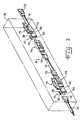
- FIG. 1is an exploded perspective view of an electrical distribution block according to the present invention
- FIG. 2is a perspective view, partially broken away, of the distribution block of FIG. 1, shown in an assembled condition from the side opposite the side shown in FIG. 1;
- FIG. 3is a perspective view of a modular electrical distribution system in which distribution blocks of the present invention are used.
- Distribution block 10includes a first connector assembly 12 and a second connector assembly 14 , each adapted for connection to each other to form an electrically coupled structure having four sites for connecting to other components of a modular electrical distribution system 16 , described in greater detail hereinafter, illustrated in a modular wall panel 18 shown in phantom lines in FIG. 3 .
- First connector assembly 12 and second connector assembly 14are joined to each other through first and second bridge portions 20 and 22 .
- First connector assembly 12is a substantially T-shaped structure, and includes a group of first branch connectors 30 and a group of second branch connectors 32 disposed and arranged in substantially opposite direction.
- First and second branch connectors 30 and 32are configured for connection to and with other components of electrical distribution system 16 to be described hereinafter.
- First connector assembly 12and specifically first bridge portion 20 thereof, includes first bridge connectors 34 electrically coupled to first and second branch connectors 30 and 32 .
- Bridge connectors 34are disposed perpendicular to first and second branch connectors 30 and 32 .
- first and second branch connectors 30 and 32 and bridge connectors 34may be formed as a series of stacked, individual terminals A, B, C, D, E, F, G and H, each such terminal being essentially T-shaped and having ends each corresponding to one of the branch connectors 30 and 32 and bridge connector 34 .
- terminal Ahas first branch connector terminal end 30 A, second branch connector terminal end 32 A and bridge connector terminal end 34 A.
- first and second branch connector ends 30 B- 30 H and 32 B- 32 H and bridge connectors 34 B-Hare also shown.
- a distribution block 10may include more or fewer first branch connectors 30 , second branch connectors 32 and bridge connectors 34 than as shown.
- a generally T-shaped housing 36is provided and includes first and second branch connector housings 40 and 42 surrounding first and second branch connectors 30 and 32 , respectively, and a bridge connector housing 44 surrounding bridge connectors 34 .
- Second connector assembly 14is also a substantially T-shaped structure, and includes a group of third branch connectors 50 and a group of fourth branch connectors 52 disposed and arranged in substantially opposite directions. Third and fourth branch connectors 50 and 52 also are configured for connection to and with other components of electrical system 16 to be described hereinafter.
- Second connector assembly 14and more specifically second bridge portion 22 thereof, further includes second bridge connectors 54 electrically coupled to third and fourth branch connectors 50 and 52 .
- Bridge connectors 54are disposed substantially perpendicular to third and fourth branch connectors 50 and 52 .
- Third and fourth branch connectors 50 and 52 and second bridge connectors 54likewise may be formed as a series of stacked individual terminals I, J, K, L, M, N, 0 and P. Each terminal is essentially T-shaped and includes third and fourth branch connector ends 50 I-P and 52 I-P, respectively, and bridge connector ends 54 I-P.
- a distribution block 10may include more or fewer third branch connectors 50 , fourth branch connectors 52 and second bridge connectors 54 than as shown.
- a generally T-shaped housing 56is provided for second connector assembly 14 and includes third and fourth branch connector housings 60 and 62 surrounding third and fourth branch connectors 50 and 52 , respectively, and a second bridge connector housing 64 surrounding bridge connectors 54 .
- First connector assembly 12 and second connector assembly 14are complementary halves forming distribution block 10 .
- First connector assembly 12 and second connector assembly 14join to each other through first and second bridge connectors 34 and 54 and first and second bridge connector housings 44 and 64 of first and second bridge portions 20 and 22 .
- First bridge connectors 34are formed as male terminals, comprising an elongated flat blade.
- Second bridge connectors 54are formed as female terminals having upper and lower elements biased toward each other at the outer ends thereof.
- First bridge connectors 34are received in second bridge connectors 54 and provide electrical conductivity therethrough. Electrical contact can be made anywhere along the lengths of first bridge connectors 34 . It should be understood that first and second bridge connectors 34 and 54 can be of other shapes and forms, and each may include a combination of male and female terminals.
- First bridge connector housing 44is provided sufficiently smaller in cross-section to be received in second bridge connector housing 64 .
- first and second bridge connectors 34 and 54 and first and second bridge connector housings 44 and 64are telescopically engaged one with the other such that they can be overlappingly engaged to a greater or lesser length as desired.
- first and second branch connectors 30 and 32which are oppositely directed relative to each other and substantially parallel to the similarly oppositely directed third and fourth branch connectors 50 and 52 , can be selectively arranged spaced a selectively greater or lesser distance from third and fourth branch connectors 50 and 52 .
- connector block 10can be adjusted to fit in modular wall panels 18 of different thickness, and can function to provide electrical service to both sides of modular wall panel 18 .
- First, second, third and fourth branch connectors 30 , 32 , 50 and 52are each similarly configured to be electrically connected to other components of modular electrical distribution system 16 , and a plurality of distribution blocks 10 can be used in configuring electrical distribution system 16 as desired.
- FIG. 3An example of the manner in which several distribution blocks 10 can be used is illustrated in FIG. 3 .
- a power entry cable 70is provided from an electrical power source (not shown) that may be an electrical breaker box or the like.
- an end connector 72 on cable 70can be connected to either first branch connectors 30 or third branch connectors 50 .
- Electrical currentis thus available at second and fourth branch connectors 32 and 52 and the other of first and third branch connectors 30 or 50 that is not connected to connector 72 of cable 70 .
- first and second branch connectors 30 and 32can be spaced a selected distance from third and fourth branch connectors 50 and 52 so that receptacles 74 connected on opposite sides of distribution block 10 are properly aligned with opposite faces of modular wall 18 .
- receptacles 74 and jumper cables 76can be connected to each other and/or to one or more terminal blocks 10 to provide a series of receptacles exposed on the opposite faces of modular wall panel 18 .
- the present inventionprovides a distribution block that is adjustable to fit within walls of different thickness. The number of different parts required for modular electrical systems in modular walls is reduced.
Landscapes
- Distribution Board (AREA)
- Connector Housings Or Holding Contact Members (AREA)
Abstract
Description
Claims (21)
Priority Applications (1)
| Application Number | Priority Date | Filing Date | Title |
|---|---|---|---|
| US10/120,749US6652288B2 (en) | 2002-04-11 | 2002-04-11 | Electrical distribution block |
Applications Claiming Priority (1)
| Application Number | Priority Date | Filing Date | Title |
|---|---|---|---|
| US10/120,749US6652288B2 (en) | 2002-04-11 | 2002-04-11 | Electrical distribution block |
Publications (2)
| Publication Number | Publication Date |
|---|---|
| US20030194884A1 US20030194884A1 (en) | 2003-10-16 |
| US6652288B2true US6652288B2 (en) | 2003-11-25 |
Family
ID=28790157
Family Applications (1)
| Application Number | Title | Priority Date | Filing Date |
|---|---|---|---|
| US10/120,749Expired - Fee RelatedUS6652288B2 (en) | 2002-04-11 | 2002-04-11 | Electrical distribution block |
Country Status (1)
| Country | Link |
|---|---|
| US (1) | US6652288B2 (en) |
Cited By (18)
| Publication number | Priority date | Publication date | Assignee | Title |
|---|---|---|---|---|
| US6939153B1 (en)* | 2003-05-14 | 2005-09-06 | Pent Technologies, Inc. | Double “E” electrical distribution block |
| US20060094290A1 (en)* | 2003-09-10 | 2006-05-04 | Pyrros Chrestos T | Modular electrical receptacle |
| US7114972B1 (en) | 2004-12-28 | 2006-10-03 | Pent Technologies, Inc. | Retro-fit receptacle mounting method and apparatus |
| US7205487B1 (en)* | 2006-03-02 | 2007-04-17 | Pent Technologies, Inc. | Method and apparatus for attaching conduit to flexible sleeving |
| US20070099491A1 (en)* | 2003-09-10 | 2007-05-03 | Pyrros Chrestos T | Modular electrical receptacle |
| WO2007081378A1 (en)* | 2005-04-29 | 2007-07-19 | Byrne Norman R | Center connect single-sided junction block |
| US20080032534A1 (en)* | 2005-02-17 | 2008-02-07 | Pent Technologies, Inc. | Method of branching power around an obstacle |
| US20080057762A1 (en)* | 2003-05-14 | 2008-03-06 | Pent Technologies, Inc. | System to place receptacles and distribution blocks |
| US20090130879A1 (en)* | 2007-08-09 | 2009-05-21 | Ross Johnson | Modular electrical distribution system for a building |
| US20090303021A1 (en)* | 2008-06-06 | 2009-12-10 | Dave Black | Networked Power and Communication Receptacle Devices |
| US20100328853A1 (en)* | 2007-08-09 | 2010-12-30 | Haworth, Inc. | Modular electrical distribution system for a building |
| US20100328852A1 (en)* | 2007-08-09 | 2010-12-30 | Haworth, Inc. | Modular electrical distribution system for a building |
| US8801445B2 (en)* | 2010-07-12 | 2014-08-12 | Norman R. Byrne | Vertical T-junction block assembly |
| US20150111403A1 (en)* | 2013-10-17 | 2015-04-23 | Norman R. Byrne | Adjustable flat wire raceway |
| US20180370462A1 (en)* | 2017-06-27 | 2018-12-27 | Iconn Systems, Llc | Electric power distribution module and system |
| US20190386441A1 (en)* | 2007-05-11 | 2019-12-19 | Norman R. Byrne | Modular electrical system utilizing four wire circuitry |
| US10866126B2 (en)* | 2019-01-06 | 2020-12-15 | Mitutoyo Corporation | Connection unit for connecting external device to measurement device |
| US20240305052A1 (en)* | 2023-03-06 | 2024-09-12 | Juniper Design Group Inc. | Low-profile track system |
Families Citing this family (4)
| Publication number | Priority date | Publication date | Assignee | Title |
|---|---|---|---|---|
| AT15294U1 (en)* | 2014-12-17 | 2017-05-15 | Zumtobel Lighting Gmbh | Distributor connector arrangement for a device carrier of a continuous line luminaire |
| DE102016104355A1 (en)* | 2016-03-10 | 2017-09-14 | Itz Innovations- Und Technologiezentrum Gmbh | Modular lighting device in the form of a light band and connection system therefor |
| US11303079B2 (en) | 2019-05-28 | 2022-04-12 | Norman R. Byrne | Modular electrical system |
| US11527875B2 (en)* | 2021-01-08 | 2022-12-13 | Group Dekko, Inc. | Mounting bracket assembly for an electrical receptacle system |
Citations (11)
| Publication number | Priority date | Publication date | Assignee | Title |
|---|---|---|---|---|
| US1865600A (en) | 1931-09-09 | 1932-07-05 | American Telephone & Telegraph | Multiswitch coupling |
| US1917009A (en) | 1931-03-17 | 1933-07-04 | Bell Telephone Labor Inc | Electrical connecter |
| US2945201A (en) | 1954-02-20 | 1960-07-12 | Kabelschlepp Gmbh | Multi-polar terminal connection for electric conductors |
| US3016509A (en) | 1954-02-20 | 1962-01-09 | Kabelschlepp Gmbh | Multi-polar terminal connection for electric conductors |
| US3065446A (en) | 1958-09-29 | 1962-11-20 | Cannon Electric Co | Electrical connector for strip cable |
| US3601759A (en) | 1969-02-07 | 1971-08-24 | Component Mfg Service Inc | Electrical connector |
| US3670291A (en) | 1970-05-14 | 1972-06-13 | Banancio Garcia | Connecting device |
| US4553798A (en)* | 1984-04-04 | 1985-11-19 | Peter Murphy | Electrical outlet |
| US5041002A (en) | 1990-04-17 | 1991-08-20 | Byrne Norman R | Extendable electrical junction assembly |
| US5941720A (en)* | 1995-11-27 | 1999-08-24 | Byrne; Norman R. | Electrical interconnection assembly |
| US6036516A (en)* | 1995-12-11 | 2000-03-14 | Byrne; Norman R. | Electrical interconnection assembly with additional outlet receptacles |
- 2002
- 2002-04-11USUS10/120,749patent/US6652288B2/ennot_activeExpired - Fee Related
Patent Citations (11)
| Publication number | Priority date | Publication date | Assignee | Title |
|---|---|---|---|---|
| US1917009A (en) | 1931-03-17 | 1933-07-04 | Bell Telephone Labor Inc | Electrical connecter |
| US1865600A (en) | 1931-09-09 | 1932-07-05 | American Telephone & Telegraph | Multiswitch coupling |
| US2945201A (en) | 1954-02-20 | 1960-07-12 | Kabelschlepp Gmbh | Multi-polar terminal connection for electric conductors |
| US3016509A (en) | 1954-02-20 | 1962-01-09 | Kabelschlepp Gmbh | Multi-polar terminal connection for electric conductors |
| US3065446A (en) | 1958-09-29 | 1962-11-20 | Cannon Electric Co | Electrical connector for strip cable |
| US3601759A (en) | 1969-02-07 | 1971-08-24 | Component Mfg Service Inc | Electrical connector |
| US3670291A (en) | 1970-05-14 | 1972-06-13 | Banancio Garcia | Connecting device |
| US4553798A (en)* | 1984-04-04 | 1985-11-19 | Peter Murphy | Electrical outlet |
| US5041002A (en) | 1990-04-17 | 1991-08-20 | Byrne Norman R | Extendable electrical junction assembly |
| US5941720A (en)* | 1995-11-27 | 1999-08-24 | Byrne; Norman R. | Electrical interconnection assembly |
| US6036516A (en)* | 1995-12-11 | 2000-03-14 | Byrne; Norman R. | Electrical interconnection assembly with additional outlet receptacles |
Cited By (39)
| Publication number | Priority date | Publication date | Assignee | Title |
|---|---|---|---|---|
| US20080057762A1 (en)* | 2003-05-14 | 2008-03-06 | Pent Technologies, Inc. | System to place receptacles and distribution blocks |
| US7946883B2 (en)* | 2003-05-14 | 2011-05-24 | Group Dekko, Inc. | System to place receptacles and distribution blocks |
| US6939153B1 (en)* | 2003-05-14 | 2005-09-06 | Pent Technologies, Inc. | Double “E” electrical distribution block |
| US7621774B2 (en) | 2003-05-14 | 2009-11-24 | Group Dekko, Inc. | System to place receptacles and distribution blocks |
| US20100112869A1 (en)* | 2003-09-10 | 2010-05-06 | Pyrros Chrestos T | Multiplex Receptacle Adapter |
| US7628643B2 (en) | 2003-09-10 | 2009-12-08 | Pyrros Chrestos T | Modular electrical receptacle |
| US7255596B2 (en) | 2003-09-10 | 2007-08-14 | Pyrros Chrestos T | Modular electrical receptacle |
| US9246258B2 (en) | 2003-09-10 | 2016-01-26 | Chrestos T. Pyrros | Multiplex receptacle adapter |
| US20070099491A1 (en)* | 2003-09-10 | 2007-05-03 | Pyrros Chrestos T | Modular electrical receptacle |
| US20090053925A1 (en)* | 2003-09-10 | 2009-02-26 | Pyrros Chrestos T | Modular Electrical Receptacle |
| US20060094290A1 (en)* | 2003-09-10 | 2006-05-04 | Pyrros Chrestos T | Modular electrical receptacle |
| US10916880B2 (en) | 2003-09-10 | 2021-02-09 | Chrestos T. Pyrros | Multiplex receptacle adapter |
| US7575470B2 (en) | 2003-09-10 | 2009-08-18 | Pyrros Chrestos T | Modular electrical receptacle |
| US20110076884A1 (en)* | 2003-09-10 | 2011-03-31 | Pyrros Chrestos T | Multiplex Receptacle Adapter |
| US7114972B1 (en) | 2004-12-28 | 2006-10-03 | Pent Technologies, Inc. | Retro-fit receptacle mounting method and apparatus |
| US7524203B2 (en)* | 2005-02-17 | 2009-04-28 | Group Dekko, Inc. | Method of branching power around an obstacle |
| US20080032534A1 (en)* | 2005-02-17 | 2008-02-07 | Pent Technologies, Inc. | Method of branching power around an obstacle |
| WO2007081378A1 (en)* | 2005-04-29 | 2007-07-19 | Byrne Norman R | Center connect single-sided junction block |
| US7205487B1 (en)* | 2006-03-02 | 2007-04-17 | Pent Technologies, Inc. | Method and apparatus for attaching conduit to flexible sleeving |
| US20190386441A1 (en)* | 2007-05-11 | 2019-12-19 | Norman R. Byrne | Modular electrical system utilizing four wire circuitry |
| US10910780B2 (en)* | 2007-05-11 | 2021-02-02 | Norman R. Byrne | Modular electrical system utilizing four wire circuitry |
| US11641083B2 (en) | 2007-05-11 | 2023-05-02 | Norman R. Byrne | Electrical junction block utilizing a pivotable connector |
| US20100328853A1 (en)* | 2007-08-09 | 2010-12-30 | Haworth, Inc. | Modular electrical distribution system for a building |
| US7697268B2 (en) | 2007-08-09 | 2010-04-13 | Haworth, Inc. | Modular electrical distribution system for a building |
| US7841878B2 (en) | 2007-08-09 | 2010-11-30 | Haworth, Inc. | Modular electrical distribution system for a building |
| US8172589B2 (en) | 2007-08-09 | 2012-05-08 | Haworth, Inc. | Modular electrical distribution system for a building |
| US8172588B2 (en) | 2007-08-09 | 2012-05-08 | Haworth, Inc. | Modular electrical distribution system for a building |
| US20100328852A1 (en)* | 2007-08-09 | 2010-12-30 | Haworth, Inc. | Modular electrical distribution system for a building |
| US20090130879A1 (en)* | 2007-08-09 | 2009-05-21 | Ross Johnson | Modular electrical distribution system for a building |
| US7648379B2 (en) | 2007-08-09 | 2010-01-19 | Haworth, Inc. | Modular electrical distribution system for a building |
| US7826202B2 (en) | 2007-08-09 | 2010-11-02 | Haworth, Inc. | Modular electrical distribution system for a building |
| US8174379B2 (en)* | 2008-06-06 | 2012-05-08 | Premier Manufacturing Group, Inc. | Networked power and communication receptacle devices |
| US20090303021A1 (en)* | 2008-06-06 | 2009-12-10 | Dave Black | Networked Power and Communication Receptacle Devices |
| US8801445B2 (en)* | 2010-07-12 | 2014-08-12 | Norman R. Byrne | Vertical T-junction block assembly |
| US9722372B2 (en)* | 2013-10-17 | 2017-08-01 | Norman R BYRNE | Longitudinally adjustable flat wire raceway |
| US20150111403A1 (en)* | 2013-10-17 | 2015-04-23 | Norman R. Byrne | Adjustable flat wire raceway |
| US20180370462A1 (en)* | 2017-06-27 | 2018-12-27 | Iconn Systems, Llc | Electric power distribution module and system |
| US10866126B2 (en)* | 2019-01-06 | 2020-12-15 | Mitutoyo Corporation | Connection unit for connecting external device to measurement device |
| US20240305052A1 (en)* | 2023-03-06 | 2024-09-12 | Juniper Design Group Inc. | Low-profile track system |
Also Published As
| Publication number | Publication date |
|---|---|
| US20030194884A1 (en) | 2003-10-16 |
Similar Documents
| Publication | Publication Date | Title |
|---|---|---|
| US6652288B2 (en) | Electrical distribution block | |
| US7641510B2 (en) | Four way jumper/half block | |
| US5073120A (en) | Power distribution unit | |
| US5096434A (en) | Electrical interconnection assembly | |
| US6540549B2 (en) | Keyed power cord | |
| US5171159A (en) | Electrical interconnection assembly | |
| US4688869A (en) | Modular electrical wiring track arrangement | |
| US6575777B2 (en) | Partition wiring system | |
| US6827592B2 (en) | Track-type electrical distribution system | |
| US5094626A (en) | Set of assembly elements intended to facilitate concurrent electrical connection of a plurality of modular automatic circuit breakers | |
| US6902415B2 (en) | Four-way electrical circuit splitter for use with modular electrical systems | |
| JP5541050B2 (en) | Power terminal block and power supply | |
| US5318454A (en) | Off-module bus electrical system (C-13) | |
| US9225101B2 (en) | Horizontal T-junction block assembly | |
| US7144264B2 (en) | Add-on electrical distribution assembly | |
| US6648671B2 (en) | Joint connector | |
| JPH05135837A (en) | Interconnected electric distribution system, conductor supporting member therefor and coupling mechanism therefor | |
| US7108532B2 (en) | Circuit selectable receptacle | |
| US6805567B2 (en) | Power distribution system | |
| US6736658B2 (en) | Power supply interconnecting device | |
| US20030194907A1 (en) | Modular receptacle coupler | |
| US5032086A (en) | Wiring harness for wall structures | |
| US12119597B2 (en) | Electrical junction box assembly | |
| US6344610B1 (en) | Rigid electrical conduct with pass-through cut-out for use in a modular wall panel | |
| CA2753810C (en) | Block mounted adjustable end |
Legal Events
| Date | Code | Title | Description |
|---|---|---|---|
| AS | Assignment | Owner name:DEKKO ENGINEERING, INC., INDIANA Free format text:ASSIGNMENT OF ASSIGNORS INTEREST;ASSIGNORS:LAUKHUF, GREGG E.;RINER, RAYMOND H.;REEL/FRAME:012791/0708 Effective date:20020404 | |
| AS | Assignment | Owner name:PENT TECHNOLOGIES, INC., INDIANA Free format text:MERGER;ASSIGNORS:CUSTOM LIGHTS, INC.;DEKKO ENGINEERING, INC.;PENT PRODUCTS, INC.;AND OTHERS;REEL/FRAME:015139/0075 Effective date:20031226 | |
| CC | Certificate of correction | ||
| AS | Assignment | Owner name:DYMAS FUNDING COMPANY, LLC, AS AGENT,ILLINOIS Free format text:SECURITY AGREEMENT;ASSIGNORS:PENT TECHNOLOGIES, INC.;DEKKO TECHNOLOGIES, LLC;REEL/FRAME:017971/0469 Effective date:20060720 Owner name:DYMAS FUNDING COMPANY, LLC, AS AGENT, ILLINOIS Free format text:SECURITY AGREEMENT;ASSIGNORS:PENT TECHNOLOGIES, INC.;DEKKO TECHNOLOGIES, LLC;REEL/FRAME:017971/0469 Effective date:20060720 | |
| FEPP | Fee payment procedure | Free format text:PAT HOLDER NO LONGER CLAIMS SMALL ENTITY STATUS, ENTITY STATUS SET TO UNDISCOUNTED (ORIGINAL EVENT CODE: STOL); ENTITY STATUS OF PATENT OWNER: LARGE ENTITY | |
| FPAY | Fee payment | Year of fee payment:4 | |
| AS | Assignment | Owner name:GROUP DEKKO, INC., INDIANA Free format text:MERGER;ASSIGNOR:PENT TECHNOLOGIES, INC.;REEL/FRAME:021936/0719 Effective date:20071227 Owner name:GROUP DEKKO, INC.,INDIANA Free format text:MERGER;ASSIGNOR:PENT TECHNOLOGIES, INC.;REEL/FRAME:021936/0719 Effective date:20071227 | |
| FPAY | Fee payment | Year of fee payment:8 | |
| AS | Assignment | Owner name:WELLS FARGO CAPITAL FINANCE, LLC, AS AGENT, ILLINO Free format text:SECURITY AGREEMENT;ASSIGNOR:GROUP DEKKO, INC.;REEL/FRAME:026503/0966 Effective date:20110624 | |
| REMI | Maintenance fee reminder mailed | ||
| LAPS | Lapse for failure to pay maintenance fees | ||
| STCH | Information on status: patent discontinuation | Free format text:PATENT EXPIRED DUE TO NONPAYMENT OF MAINTENANCE FEES UNDER 37 CFR 1.362 | |
| FP | Lapsed due to failure to pay maintenance fee | Effective date:20151125 |