US6652179B2 - Sealing cap for ball joint assembly - Google Patents
Sealing cap for ball joint assemblyDownload PDFInfo
- Publication number
- US6652179B2 US6652179B2US09/916,651US91665101AUS6652179B2US 6652179 B2US6652179 B2US 6652179B2US 91665101 AUS91665101 AUS 91665101AUS 6652179 B2US6652179 B2US 6652179B2
- Authority
- US
- United States
- Prior art keywords
- sealing
- ball
- joint assembly
- sealing cap
- ball joint
- Prior art date
- Legal status (The legal status is an assumption and is not a legal conclusion. Google has not performed a legal analysis and makes no representation as to the accuracy of the status listed.)
- Expired - Lifetime
Links
Images

Classifications
- F—MECHANICAL ENGINEERING; LIGHTING; HEATING; WEAPONS; BLASTING
- F16—ENGINEERING ELEMENTS AND UNITS; GENERAL MEASURES FOR PRODUCING AND MAINTAINING EFFECTIVE FUNCTIONING OF MACHINES OR INSTALLATIONS; THERMAL INSULATION IN GENERAL
- F16D—COUPLINGS FOR TRANSMITTING ROTATION; CLUTCHES; BRAKES
- F16D1/00—Couplings for rigidly connecting two coaxial shafts or other movable machine elements
- F16D1/12—Couplings for rigidly connecting two coaxial shafts or other movable machine elements allowing adjustment of the parts about the axis
- F—MECHANICAL ENGINEERING; LIGHTING; HEATING; WEAPONS; BLASTING
- F16—ENGINEERING ELEMENTS AND UNITS; GENERAL MEASURES FOR PRODUCING AND MAINTAINING EFFECTIVE FUNCTIONING OF MACHINES OR INSTALLATIONS; THERMAL INSULATION IN GENERAL
- F16C—SHAFTS; FLEXIBLE SHAFTS; ELEMENTS OR CRANKSHAFT MECHANISMS; ROTARY BODIES OTHER THAN GEARING ELEMENTS; BEARINGS
- F16C11/00—Pivots; Pivotal connections
- F16C11/04—Pivotal connections
- F16C11/06—Ball-joints; Other joints having more than one degree of angular freedom, i.e. universal joints
- F16C11/0666—Sealing means between the socket and the inner member shaft
- F16C11/0671—Sealing means between the socket and the inner member shaft allowing operative relative movement of joint parts due to flexing of the sealing means
- F—MECHANICAL ENGINEERING; LIGHTING; HEATING; WEAPONS; BLASTING
- F16—ENGINEERING ELEMENTS AND UNITS; GENERAL MEASURES FOR PRODUCING AND MAINTAINING EFFECTIVE FUNCTIONING OF MACHINES OR INSTALLATIONS; THERMAL INSULATION IN GENERAL
- F16C—SHAFTS; FLEXIBLE SHAFTS; ELEMENTS OR CRANKSHAFT MECHANISMS; ROTARY BODIES OTHER THAN GEARING ELEMENTS; BEARINGS
- F16C11/00—Pivots; Pivotal connections
- F16C11/04—Pivotal connections
- F16C11/06—Ball-joints; Other joints having more than one degree of angular freedom, i.e. universal joints
- F16C11/0619—Ball-joints; Other joints having more than one degree of angular freedom, i.e. universal joints the female part comprising a blind socket receiving the male part
- F16C11/0623—Construction or details of the socket member
- F16C11/0628—Construction or details of the socket member with linings
- F16C11/0633—Construction or details of the socket member with linings the linings being made of plastics
- F—MECHANICAL ENGINEERING; LIGHTING; HEATING; WEAPONS; BLASTING
- F16—ENGINEERING ELEMENTS AND UNITS; GENERAL MEASURES FOR PRODUCING AND MAINTAINING EFFECTIVE FUNCTIONING OF MACHINES OR INSTALLATIONS; THERMAL INSULATION IN GENERAL
- F16C—SHAFTS; FLEXIBLE SHAFTS; ELEMENTS OR CRANKSHAFT MECHANISMS; ROTARY BODIES OTHER THAN GEARING ELEMENTS; BEARINGS
- F16C2326/00—Articles relating to transporting
- F16C2326/01—Parts of vehicles in general
- F16C2326/05—Vehicle suspensions, e.g. bearings, pivots or connecting rods used therein
- F—MECHANICAL ENGINEERING; LIGHTING; HEATING; WEAPONS; BLASTING
- F16—ENGINEERING ELEMENTS AND UNITS; GENERAL MEASURES FOR PRODUCING AND MAINTAINING EFFECTIVE FUNCTIONING OF MACHINES OR INSTALLATIONS; THERMAL INSULATION IN GENERAL
- F16C—SHAFTS; FLEXIBLE SHAFTS; ELEMENTS OR CRANKSHAFT MECHANISMS; ROTARY BODIES OTHER THAN GEARING ELEMENTS; BEARINGS
- F16C2326/00—Articles relating to transporting
- F16C2326/20—Land vehicles
- F16C2326/24—Steering systems, e.g. steering rods or columns
- Y—GENERAL TAGGING OF NEW TECHNOLOGICAL DEVELOPMENTS; GENERAL TAGGING OF CROSS-SECTIONAL TECHNOLOGIES SPANNING OVER SEVERAL SECTIONS OF THE IPC; TECHNICAL SUBJECTS COVERED BY FORMER USPC CROSS-REFERENCE ART COLLECTIONS [XRACs] AND DIGESTS
- Y10—TECHNICAL SUBJECTS COVERED BY FORMER USPC
- Y10T—TECHNICAL SUBJECTS COVERED BY FORMER US CLASSIFICATION
- Y10T403/00—Joints and connections
- Y10T403/32—Articulated members
- Y10T403/32606—Pivoted
- Y10T403/32631—Universal ball and socket
- Y10T403/32721—Elastomeric seat
- Y—GENERAL TAGGING OF NEW TECHNOLOGICAL DEVELOPMENTS; GENERAL TAGGING OF CROSS-SECTIONAL TECHNOLOGIES SPANNING OVER SEVERAL SECTIONS OF THE IPC; TECHNICAL SUBJECTS COVERED BY FORMER USPC CROSS-REFERENCE ART COLLECTIONS [XRACs] AND DIGESTS
- Y10—TECHNICAL SUBJECTS COVERED BY FORMER USPC
- Y10T—TECHNICAL SUBJECTS COVERED BY FORMER US CLASSIFICATION
- Y10T403/00—Joints and connections
- Y10T403/32—Articulated members
- Y10T403/32606—Pivoted
- Y10T403/32631—Universal ball and socket
- Y10T403/32729—Externally packed
Definitions
- the present inventionrelates to ball joint assemblies, and more particularly to structure of a sealing cap in a ball joint assembly.
- Spherical or ball joints intended for various industrial applicationsneed a sealing system to prevent impurities, such as road dirt, sand and water, penetrate in its interior. Consequently, the presence of impurities between the frictioning parts of the ball joint assembly tends to cause a premature wear of its components and affects the operation of the ball joint assembly.
- the ball joint assembliesare well known in the prior art.
- the typical ball joint assemblynormally comprises a ball rod having a substantially spherical ball member at its one end and an elongated substantially cylindrical shank member at its other end.
- the ball member of the ball rodis coupled to a single or divided bearing and is housed within an interior of a ball joint casing.
- the ball joint casinghas an opening through which the ball portion of the ball rod and the bearing are mounted within the ball joint casing.
- the ball member of the ball rodis sealed within the ball joint casing by a flexible sealing cap fixed to the casing so as to prevent the penetration of impurities into the interior of the joint casing.
- the sealing capis made of rubber, or any other similar elastic material.
- the sealing caphas two open ends. A first end having an opening of a bigger diameter is coupled to an external surface of the casing, and a second end having an opening of a smaller diameter is mounted about the shank member of the ball rod.
- the ends of the sealing capare coupled to the casing and the shank member of the ball rod by means of corresponding straining rings, such as C-rings, pressing the ends of the sealing cap against the external surface of the casing and the shank member, respectively.
- the present inventionprovides a novel sealing cap for a ball joint assembly for use in a motor vehicle.
- the spherical joint assembly in accordance with the present inventioncomprises a ball rod having a ball member at its one end and an elongated shank member at its other end, a bearing receiving the head member of the ball rod, a casing housing the bearing, and a sealing cap having a first end secured to the casing by means of a straining ring, and a second end mounted about the shank member.
- the shank member of the ball rodis provided with an annular crown member and an annular flange member axially spaced from the crown member. The crown member and the flange member form an annular sealing seat receiving the second end of the sealing cap.
- the second end of the sealing capis provided with a sealing bulge and a flexible sealing lip extending from said sealing edge, so that when the second end of the sealing cap is mounted over said sealing seat of said shank member, the sealing lip deforms and bends over towards the sealing edge.
- the sealing cap of the present inventionsubstantially improves sealing of the ball joint assembly over the prior art, eliminates the second straining ring used for coupling the second end of the sealing cap to the shank member of the ball rod, provides more reliable sealing, and makes the process of assembling the ball joint assembly easier and less laborious.
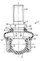
- FIG. 1is a cross-sectional view of a spherical joint assembly in accordance with the preferred embodiment of the present invention
- FIG. 2is a cross-sectional view of a sealing cap in accordance with the preferred embodiment of the present invention.
- FIG. 1that shows the preferred embodiment of the invention, illustrates a spherical or ball joint assembly 1 comprising a ball rod 2 having a substantially spherical ball member 4 and an elongated generally cylindrical shank member 6 extending from the head member 4 .
- the spherical head member 4is received in a bearing 8 , which, in turn, is housed in an interior cavity defined by a ball joint casing 10 .
- the shank member 6 of the ball rod 2projects through an opening in one end of the casing 10 .
- the shank member 6 of the ball rod 2is fastened to a moving part (not shown) that needs angular and rotational movement relative to the ball joint casing 10 .
- the angular and rotational movement provided between the ball rod 2 and the ball joint casing 10must comply with the requirements of the moving parts that are connected thereto.
- the ball joint assembly 1further comprises a sealing cap 12 provided at the end of the casing 10 for preventing prevent impurities, such as road dirt, sand and water, from penetrating into the ball joint assembly 1 .
- the sealing cap 12has a first end 14 secured to the casing 10 , and a second end 16 mounted about the shank member 6 of the ball rod 2 .
- the sealing cap 12is made of elastomeric material, such as rubber, polyurethane or soft-type synthetic resin.
- the first end 14 of the sealing cap 12is attached to an outer peripheral surface of the casing 10 by means of a straining ring 18 that firmly presses the end 14 of the sealing cap 12 against the outer peripheral surface of the casing 10 .
- the first end 14 of the sealing cap 12has a generally cylindrical inner peripheral surface 15 that engages an outer peripheral surface of the casing 10 by means of a straining ring 18 , engageable with groove 14 ′, that firmly presses the inner surface 15 of the first end 14 of the sealing cap 12 against the outer peripheral surface of the casing 10 , thereby effectively sealing the ball joint assembly 1 .
- the shank member 6 of the ball rod 2is provided with an annular crown member 28 and an annular flange member 30 axially spaced from the crown member 28 .
- the crown member 28 and the flange member 30form an annular sealing seat 32 receiving the second end 16 of the sealing cap 12 .
- a front face 31 of the flange member 30facing the crown member 28 , has generally frusto-conical surface.
- the second end 16 of the sealing cap 12is, in turn, provided with a sealing bulge 20 and a flexible sealing lip 22 extending from said sealing bulge 20 , so that when the second end 16 of the sealing cap 12 is mounted over the sealing seat 32 of said shank member 6 , the sealing lip 22 deforms and bends over toward the sealing bulge 20 forming an enclosed channel 24 therebetween.
- the sealing cap of the present inventionsubstantially improves sealing of the ball joint assembly over the prior art, eliminates the second straining ring used for coupling the second end of the sealing cap to the shank member of the ball rod, provides more reliable sealing, and makes the process of assembling the ball joint assembly easier and less laborious.
Landscapes
- Engineering & Computer Science (AREA)
- General Engineering & Computer Science (AREA)
- Mechanical Engineering (AREA)
- Pivots And Pivotal Connections (AREA)
- Sealing Devices (AREA)
Abstract
Description
1. Field of the Invention
The present invention relates to ball joint assemblies, and more particularly to structure of a sealing cap in a ball joint assembly.
2. Description of the Prior Art
Spherical or ball joints intended for various industrial applications, such as steering and suspension systems of automotive vehicles, need a sealing system to prevent impurities, such as road dirt, sand and water, penetrate in its interior. Consequently, the presence of impurities between the frictioning parts of the ball joint assembly tends to cause a premature wear of its components and affects the operation of the ball joint assembly.
The ball joint assemblies are well known in the prior art. The typical ball joint assembly normally comprises a ball rod having a substantially spherical ball member at its one end and an elongated substantially cylindrical shank member at its other end. The ball member of the ball rod is coupled to a single or divided bearing and is housed within an interior of a ball joint casing. The ball joint casing has an opening through which the ball portion of the ball rod and the bearing are mounted within the ball joint casing. The ball member of the ball rod is sealed within the ball joint casing by a flexible sealing cap fixed to the casing so as to prevent the penetration of impurities into the interior of the joint casing.
Usually, the sealing cap is made of rubber, or any other similar elastic material. The sealing cap has two open ends. A first end having an opening of a bigger diameter is coupled to an external surface of the casing, and a second end having an opening of a smaller diameter is mounted about the shank member of the ball rod. The ends of the sealing cap are coupled to the casing and the shank member of the ball rod by means of corresponding straining rings, such as C-rings, pressing the ends of the sealing cap against the external surface of the casing and the shank member, respectively.
This way of coupling of the sealing cap to the shank member of the ball rod, however, has proven itself inefficient due to some undesirable effects, related to the angular movement of the ball rod in its maximum limits, and the fact that the damage the sealing cap may occur during the mounting of straining rings on the ends thereof.
The present invention provides a novel sealing cap for a ball joint assembly for use in a motor vehicle. The spherical joint assembly in accordance with the present invention comprises a ball rod having a ball member at its one end and an elongated shank member at its other end, a bearing receiving the head member of the ball rod, a casing housing the bearing, and a sealing cap having a first end secured to the casing by means of a straining ring, and a second end mounted about the shank member. The shank member of the ball rod is provided with an annular crown member and an annular flange member axially spaced from the crown member. The crown member and the flange member form an annular sealing seat receiving the second end of the sealing cap. The second end of the sealing cap is provided with a sealing bulge and a flexible sealing lip extending from said sealing edge, so that when the second end of the sealing cap is mounted over said sealing seat of said shank member, the sealing lip deforms and bends over towards the sealing edge.
Therefore, the sealing cap of the present invention substantially improves sealing of the ball joint assembly over the prior art, eliminates the second straining ring used for coupling the second end of the sealing cap to the shank member of the ball rod, provides more reliable sealing, and makes the process of assembling the ball joint assembly easier and less laborious.
Other objects and advantages of the invention will become apparent from a study of the following specification when viewed in light of the accompanying drawings, wherein:
FIG. 1 is a cross-sectional view of a spherical joint assembly in accordance with the preferred embodiment of the present invention;
FIG. 2 is a cross-sectional view of a sealing cap in accordance with the preferred embodiment of the present invention.
The preferred embodiment of the present invention will now be described with the reference to accompanying drawings.
The FIG. 1 that shows the preferred embodiment of the invention, illustrates a spherical or ball joint assembly1 comprising aball rod 2 having a substantiallyspherical ball member 4 and an elongated generallycylindrical shank member 6 extending from thehead member 4. Thespherical head member 4 is received in abearing 8, which, in turn, is housed in an interior cavity defined by aball joint casing 10.
Theshank member 6 of theball rod 2 projects through an opening in one end of thecasing 10. Theshank member 6 of theball rod 2 is fastened to a moving part (not shown) that needs angular and rotational movement relative to theball joint casing 10. Thus, the angular and rotational movement provided between theball rod 2 and theball joint casing 10 must comply with the requirements of the moving parts that are connected thereto.
The ball joint assembly1 further comprises a sealingcap 12 provided at the end of thecasing 10 for preventing prevent impurities, such as road dirt, sand and water, from penetrating into the ball joint assembly1. The sealingcap 12 has afirst end 14 secured to thecasing 10, and asecond end 16 mounted about theshank member 6 of theball rod 2. The sealingcap 12 is made of elastomeric material, such as rubber, polyurethane or soft-type synthetic resin.
Thefirst end 14 of the sealingcap 12 is attached to an outer peripheral surface of thecasing 10 by means of astraining ring 18 that firmly presses theend 14 of the sealingcap 12 against the outer peripheral surface of thecasing 10.
Thefirst end 14 of thesealing cap 12 has a generally cylindrical innerperipheral surface 15 that engages an outer peripheral surface of thecasing 10 by means of a strainingring 18, engageable withgroove 14′, that firmly presses theinner surface 15 of thefirst end 14 of the sealingcap 12 against the outer peripheral surface of thecasing 10, thereby effectively sealing the ball joint assembly1.
Theshank member 6 of theball rod 2 is provided with anannular crown member 28 and anannular flange member 30 axially spaced from thecrown member 28. Thecrown member 28 and theflange member 30 form anannular sealing seat 32 receiving thesecond end 16 of the sealingcap 12. Preferably, afront face 31 of theflange member 30, facing thecrown member 28, has generally frusto-conical surface.
Thesecond end 16 of thesealing cap 12, as best seen in FIG. 2, is, in turn, provided with asealing bulge 20 and aflexible sealing lip 22 extending from said sealingbulge 20, so that when thesecond end 16 of the sealingcap 12 is mounted over the sealingseat 32 of saidshank member 6, thesealing lip 22 deforms and bends over toward thesealing bulge 20 forming an enclosedchannel 24 therebetween.
Therefore, the sealing cap of the present invention substantially improves sealing of the ball joint assembly over the prior art, eliminates the second straining ring used for coupling the second end of the sealing cap to the shank member of the ball rod, provides more reliable sealing, and makes the process of assembling the ball joint assembly easier and less laborious.
The foregoing description of the preferred embodiments of the present invention has been presented for the purpose of illustration in accordance with the provisions of the Patent Statutes. It is not intended to be exhaustive or to limit the invention to the precise forms disclosed. The embodiments disclosed hereinabove were chosen in order to best illustrate the principles of the present invention and its practical application to thereby enable those of ordinary skill in the art to best utilize the invention in various embodiments and with various modifications as are suited to the particular use contemplated, as long as the principles described herein are followed. This application is therefore intended to cover any variations, uses, or adaptations of the invention using its general principles. Further, this application is intended to cover such departures from the present disclosure as come within known or customary practice in the art to which this invention pertains. Thus, changes can be made in the above-described invention without departing from the intent and scope thereof. It is also intended that the scope of the present invention be defined by the claims appended thereto.
Claims (6)
1. A ball joint assembly comprising:
a ball rod having a substantially spherical ball member and an elongated shank member extending from said ball member;
a casing defining an interior cavity for housing said ball member of said ball rod; and
a sealing cap having a first end secured to said casing and a second end mounted about said shank member of said ball rod;
said second end is provided with a sealing bulge and a sealing lip extending from said sealing bulge, said sealing lip is flexible relative to said sealing bulge, wherein said shank member is provided with a sealing seat receiving said second end of the sealing cap so that said sealing lip deforms and bends over said sealing bulge forming an enclosed channel therebetween.
2. The ball joint assembly as defined inclaim 1 , wherein said shank member of said ball rod has a crown member and a flange member axially spaced from the crown member, said crown member and said flange member form said sealing seat therebetween.
3. The ball joint assembly as defined inclaim 2 , wherein said flange member has a front face facing said crown member, said front face has a substantially frusto-conical surface.
4. A combination of a sealing cap and a ball joint assembly, said sealing cap comprising:
a first end for securing to a casing of said ball joint assembly; and
a second end for coupling to a pin member of said ball joint assembly,
wherein said second end is provided with a sealing bulge and a sealing lip extending from said sealing bulge, said sealing lip is flexible relative to said sealing bulge, and
wherein said ball joint assembly includes a ball rod having a substantially spherical ball member and an elongated shank member extending from said ball member, and a casing housing said ball member of said ball rod, said shank member is provided with a sealing seat receiving said second end of the sealing cap so that said sealing lip deforms and bends over said sealing bulge forming an enclosed channel therebetween.
5. The combination as defined inclaim 4 , wherein said shank member of said ball rod has a crown member and a flange member axially spaced from the crown member, said crown member and said flange member form said sealing seat therebetween.
6. The combination as defined inclaim 5 , wherein said flange member has a front face facing said crown member, said front face has a substantially frusto-conical surface.
Applications Claiming Priority (3)
| Application Number | Priority Date | Filing Date | Title |
|---|---|---|---|
| BRPI0003450-9 | 2000-07-28 | ||
| BR0003450 | 2000-07-28 | ||
| BRPI0003450-9ABR0003450B1 (en) | 2000-07-28 | 2000-07-28 | spherical joint sealant. |
Publications (2)
| Publication Number | Publication Date |
|---|---|
| US20020028106A1 US20020028106A1 (en) | 2002-03-07 |
| US6652179B2true US6652179B2 (en) | 2003-11-25 |
Family
ID=3944887
Family Applications (1)
| Application Number | Title | Priority Date | Filing Date |
|---|---|---|---|
| US09/916,651Expired - LifetimeUS6652179B2 (en) | 2000-07-28 | 2001-07-30 | Sealing cap for ball joint assembly |
Country Status (3)
| Country | Link |
|---|---|
| US (1) | US6652179B2 (en) |
| BR (1) | BR0003450B1 (en) |
| DE (1) | DE10135822A1 (en) |
Cited By (17)
| Publication number | Priority date | Publication date | Assignee | Title |
|---|---|---|---|---|
| US6962351B2 (en)* | 2002-05-27 | 2005-11-08 | Dana Corporation | Housing for retaining a sealing cap on a ball and socket joint |
| US20070065057A1 (en)* | 2003-04-01 | 2007-03-22 | Minebea Co., Ltd. | Sealed spherical bearing |
| US20070297850A1 (en)* | 2006-06-13 | 2007-12-27 | Industria Auxiliar Alavesa, S.A. (Inauxa, S.A.) | Ball joint device, manufacturing process and apparatus |
| US20090047063A1 (en)* | 2005-03-15 | 2009-02-19 | Thk Co., Ltd. | Ball joint |
| US20090074504A1 (en)* | 2004-11-25 | 2009-03-19 | Industria Auxilliar Alavesa, S.A. (Inauxa, S.A.) | Ball joint device |
| US20100119297A1 (en)* | 2008-11-07 | 2010-05-13 | Trw Automotive U.S. Llc | Sealing structure for use with a ball and socket joint |
| US7862250B2 (en) | 2008-03-13 | 2011-01-04 | Disa Automotive, Inc. | Dust boot assemblies and apparatus for providing grease relief for a dust boot |
| US20120148336A1 (en)* | 2009-10-22 | 2012-06-14 | Shimazawa Toshihiro | Ball joint |
| US20130022299A1 (en)* | 2011-07-21 | 2013-01-24 | Roller Bearing Company Of America, Inc. | Low friction seal for bearings |
| US20130033016A1 (en)* | 2010-04-21 | 2013-02-07 | Nhk Spring Co., Ltd. | Ball stud, dust cover, and stabilizer link |
| US20130287478A1 (en)* | 2012-04-25 | 2013-10-31 | Jtekt Corporation | Ball joint |
| US9316257B2 (en) | 2011-04-01 | 2016-04-19 | Roller Bearing Company Of America, Inc. | Spherical bearing with sealing member member |
| US9562567B2 (en) | 2014-02-07 | 2017-02-07 | Roller Bearing Company Of America, Inc. | Spherical bearing with axially compressed annular seal |
| US9709087B2 (en) | 2015-07-28 | 2017-07-18 | Borgwarner Inc. | Preload loss prevention system for a clamping ball stud |
| US9958011B2 (en) | 2011-04-01 | 2018-05-01 | Roller Bearing Company Of America, Inc. | Bearing assembly having surface protrusions and a seal |
| US10495139B2 (en)* | 2015-05-11 | 2019-12-03 | Thk Co., Ltd. | Ball joint and method for manufacturing ball joint |
| US11739791B2 (en)* | 2018-10-11 | 2023-08-29 | Nok Corporation | Ball joint and dust cover |
Families Citing this family (2)
| Publication number | Priority date | Publication date | Assignee | Title |
|---|---|---|---|---|
| US20040165940A1 (en)* | 2003-02-21 | 2004-08-26 | Fotino William A. | Ball stud for suspension system |
| DE102004007331B4 (en)* | 2004-02-14 | 2006-08-03 | Contitech Vibration Control Gmbh | ball joint |
Citations (13)
| Publication number | Priority date | Publication date | Assignee | Title |
|---|---|---|---|---|
| US2308073A (en)* | 1940-08-02 | 1943-01-12 | Universal Products Co Inc | Boot for universal joints |
| US3204427A (en)* | 1963-05-27 | 1965-09-07 | Chrysler Corp | Universal joint |
| GB1006462A (en)* | 1963-03-13 | 1965-10-06 | Eng Productions Clevedon Ltd | Improvements in flexible sealing sleeves for ball joints |
| US3248955A (en)* | 1962-06-29 | 1966-05-03 | Trw Inc | Pressure relief boot seal |
| US3490343A (en)* | 1967-10-12 | 1970-01-20 | Dayton Steel Foundry Co | Hydraulic disk brakes |
| US3910588A (en)* | 1973-04-26 | 1975-10-07 | George Alfred Braisby Austin | Sealing washers, and fastener-sealing washer assemblies |
| US4154546A (en)* | 1977-06-21 | 1979-05-15 | Automotive Products Limited | Pin and socket joint |
| DE2942005A1 (en)* | 1979-10-17 | 1981-05-07 | Hanomag GmbH, 3000 Hannover | Ball joint with protruding coupling rod - includes elastic below sleeve located in taper housing to seal ball location |
| US4493676A (en)* | 1982-02-23 | 1985-01-15 | Uni-Cardan Aktiengesellschaft | Rotary constant velocity joint |
| US4936635A (en)* | 1988-04-11 | 1990-06-26 | Jidosha Kiki Co., Ltd. | Brake booster |
| US5100254A (en)* | 1990-04-26 | 1992-03-31 | Trw Steering & Industrial Products Co., Ltd. | Protector for ball joint |
| US5538275A (en)* | 1993-12-17 | 1996-07-23 | Chrysler Corporation | Ball joint seal with heat shield |
| US5876149A (en)* | 1995-06-29 | 1999-03-02 | Trw Fahrwerksysteme Gmbh & Co. Kg | Ball joint |
- 2000
- 2000-07-28BRBRPI0003450-9Apatent/BR0003450B1/ennot_activeIP Right Cessation
- 2001
- 2001-05-22DEDE10135822Apatent/DE10135822A1/ennot_activeWithdrawn
- 2001-07-30USUS09/916,651patent/US6652179B2/ennot_activeExpired - Lifetime
Patent Citations (13)
| Publication number | Priority date | Publication date | Assignee | Title |
|---|---|---|---|---|
| US2308073A (en)* | 1940-08-02 | 1943-01-12 | Universal Products Co Inc | Boot for universal joints |
| US3248955A (en)* | 1962-06-29 | 1966-05-03 | Trw Inc | Pressure relief boot seal |
| GB1006462A (en)* | 1963-03-13 | 1965-10-06 | Eng Productions Clevedon Ltd | Improvements in flexible sealing sleeves for ball joints |
| US3204427A (en)* | 1963-05-27 | 1965-09-07 | Chrysler Corp | Universal joint |
| US3490343A (en)* | 1967-10-12 | 1970-01-20 | Dayton Steel Foundry Co | Hydraulic disk brakes |
| US3910588A (en)* | 1973-04-26 | 1975-10-07 | George Alfred Braisby Austin | Sealing washers, and fastener-sealing washer assemblies |
| US4154546A (en)* | 1977-06-21 | 1979-05-15 | Automotive Products Limited | Pin and socket joint |
| DE2942005A1 (en)* | 1979-10-17 | 1981-05-07 | Hanomag GmbH, 3000 Hannover | Ball joint with protruding coupling rod - includes elastic below sleeve located in taper housing to seal ball location |
| US4493676A (en)* | 1982-02-23 | 1985-01-15 | Uni-Cardan Aktiengesellschaft | Rotary constant velocity joint |
| US4936635A (en)* | 1988-04-11 | 1990-06-26 | Jidosha Kiki Co., Ltd. | Brake booster |
| US5100254A (en)* | 1990-04-26 | 1992-03-31 | Trw Steering & Industrial Products Co., Ltd. | Protector for ball joint |
| US5538275A (en)* | 1993-12-17 | 1996-07-23 | Chrysler Corporation | Ball joint seal with heat shield |
| US5876149A (en)* | 1995-06-29 | 1999-03-02 | Trw Fahrwerksysteme Gmbh & Co. Kg | Ball joint |
Cited By (22)
| Publication number | Priority date | Publication date | Assignee | Title |
|---|---|---|---|---|
| US6962351B2 (en)* | 2002-05-27 | 2005-11-08 | Dana Corporation | Housing for retaining a sealing cap on a ball and socket joint |
| US20070065057A1 (en)* | 2003-04-01 | 2007-03-22 | Minebea Co., Ltd. | Sealed spherical bearing |
| US7568840B2 (en)* | 2003-04-01 | 2009-08-04 | Mineba Co. Ltd. | Sealed spherical bearing |
| US20090074504A1 (en)* | 2004-11-25 | 2009-03-19 | Industria Auxilliar Alavesa, S.A. (Inauxa, S.A.) | Ball joint device |
| US20090047063A1 (en)* | 2005-03-15 | 2009-02-19 | Thk Co., Ltd. | Ball joint |
| CN101142415B (en)* | 2005-03-15 | 2011-09-07 | Thk株式会社 | Ball joint |
| US20070297850A1 (en)* | 2006-06-13 | 2007-12-27 | Industria Auxiliar Alavesa, S.A. (Inauxa, S.A.) | Ball joint device, manufacturing process and apparatus |
| US7862250B2 (en) | 2008-03-13 | 2011-01-04 | Disa Automotive, Inc. | Dust boot assemblies and apparatus for providing grease relief for a dust boot |
| US8414215B2 (en)* | 2008-11-07 | 2013-04-09 | Trw Automotive U.S. Llc | Sealing structure for use with a ball and socket joint |
| US20100119297A1 (en)* | 2008-11-07 | 2010-05-13 | Trw Automotive U.S. Llc | Sealing structure for use with a ball and socket joint |
| US20120148336A1 (en)* | 2009-10-22 | 2012-06-14 | Shimazawa Toshihiro | Ball joint |
| US9133931B2 (en)* | 2010-04-21 | 2015-09-15 | Nhk Spring Co., Ltd. | Ball stud, dust cover, and stabilizer link |
| US20130033016A1 (en)* | 2010-04-21 | 2013-02-07 | Nhk Spring Co., Ltd. | Ball stud, dust cover, and stabilizer link |
| US9316257B2 (en) | 2011-04-01 | 2016-04-19 | Roller Bearing Company Of America, Inc. | Spherical bearing with sealing member member |
| US9958011B2 (en) | 2011-04-01 | 2018-05-01 | Roller Bearing Company Of America, Inc. | Bearing assembly having surface protrusions and a seal |
| US8783953B2 (en)* | 2011-07-21 | 2014-07-22 | Roller Bearing Company Of America, Inc. | Low friction seal for bearings |
| US20130022299A1 (en)* | 2011-07-21 | 2013-01-24 | Roller Bearing Company Of America, Inc. | Low friction seal for bearings |
| US20130287478A1 (en)* | 2012-04-25 | 2013-10-31 | Jtekt Corporation | Ball joint |
| US9562567B2 (en) | 2014-02-07 | 2017-02-07 | Roller Bearing Company Of America, Inc. | Spherical bearing with axially compressed annular seal |
| US10495139B2 (en)* | 2015-05-11 | 2019-12-03 | Thk Co., Ltd. | Ball joint and method for manufacturing ball joint |
| US9709087B2 (en) | 2015-07-28 | 2017-07-18 | Borgwarner Inc. | Preload loss prevention system for a clamping ball stud |
| US11739791B2 (en)* | 2018-10-11 | 2023-08-29 | Nok Corporation | Ball joint and dust cover |
Also Published As
| Publication number | Publication date |
|---|---|
| BR0003450B1 (en) | 2009-01-13 |
| BR0003450A (en) | 2004-06-08 |
| US20020028106A1 (en) | 2002-03-07 |
| DE10135822A1 (en) | 2002-04-25 |
Similar Documents
| Publication | Publication Date | Title |
|---|---|---|
| US6652179B2 (en) | Sealing cap for ball joint assembly | |
| US3381987A (en) | Double wall seal for articulated joints | |
| US5653545A (en) | Ball-and-socket joint for motor vehicles | |
| US4092078A (en) | Elastic connection for an axial joint with connecting linkage of a motor vehicle steering gear | |
| US5011321A (en) | Ball joint for stabilizer | |
| JP4741444B2 (en) | Tire valve unit | |
| US8714861B2 (en) | Sealing assembly of a ball joint and ball joint | |
| EP0779442B1 (en) | Joint assembly | |
| US6171012B1 (en) | Radial ball-and-socket joint for a motor vehicle | |
| US7017890B2 (en) | Rubber bearing with anti-vibration system | |
| US8137021B2 (en) | Sealing element for a ball and socket joint | |
| US5836235A (en) | Piston for hydraulic actuating cylinders | |
| CN107614900A (en) | ball joint | |
| US20090097908A1 (en) | Dust Cover | |
| FR2531161A1 (en) | SEALING DEVICE, IN PARTICULAR FOR UNIVERSAL JOINT | |
| HK1080536A1 (en) | Protective cap for a balljoint | |
| JP4514937B2 (en) | Ball joint | |
| US6685377B2 (en) | Arrangement of bearing and box for ball joint | |
| EP2292941B1 (en) | Assembly including a ball-joint dust cover | |
| EP1048864B1 (en) | A boot for a constant velocity universal joint | |
| US4527803A (en) | Bellows seal with groove edge folded over bead, for ball and socket joints | |
| US5558580A (en) | Boot | |
| US6648340B2 (en) | Ring for fixing of sealing cover on ball joint | |
| US6739789B2 (en) | Flanged ball pin and method for manufacturing thereof | |
| US7097381B2 (en) | Joint |
Legal Events
| Date | Code | Title | Description |
|---|---|---|---|
| AS | Assignment | Owner name:DANA INDUSTRIAL S/A, BRAZIL Free format text:ASSIGNMENT OF ASSIGNORS INTEREST;ASSIGNOR:DE FREITAS, ADEMILSON VLADEMIR;REEL/FRAME:014393/0338 Effective date:20030818 | |
| STCF | Information on status: patent grant | Free format text:PATENTED CASE | |
| FPAY | Fee payment | Year of fee payment:4 | |
| FEPP | Fee payment procedure | Free format text:PAYOR NUMBER ASSIGNED (ORIGINAL EVENT CODE: ASPN); ENTITY STATUS OF PATENT OWNER: LARGE ENTITY | |
| FPAY | Fee payment | Year of fee payment:8 | |
| FPAY | Fee payment | Year of fee payment:12 | |
| AS | Assignment | Owner name:DANA INDUSTRIAS LTDA, BRAZIL Free format text:MERGER;ASSIGNOR:DANA INDUSTRIAL LTDA;REEL/FRAME:045223/0462 Effective date:20031015 | |
| AS | Assignment | Owner name:DANA SPICER INDUSTRIA E COMERCIO DE AUTOPECAS LTDA Free format text:ASSIGNMENT OF ASSIGNORS INTEREST;ASSIGNOR:DANA INDUSTRIAS LTDA;REEL/FRAME:045879/0648 Effective date:20180511 |