US6651833B2 - Self sealing cap with spring and post - Google Patents
Self sealing cap with spring and postDownload PDFInfo
- Publication number
- US6651833B2 US6651833B2US10/072,269US7226902AUS6651833B2US 6651833 B2US6651833 B2US 6651833B2US 7226902 AUS7226902 AUS 7226902AUS 6651833 B2US6651833 B2US 6651833B2
- Authority
- US
- United States
- Prior art keywords
- cap
- cap assembly
- spring
- post
- assembly
- Prior art date
- Legal status (The legal status is an assumption and is not a legal conclusion. Google has not performed a legal analysis and makes no representation as to the accuracy of the status listed.)
- Expired - Fee Related
Links
Images


Classifications
- B—PERFORMING OPERATIONS; TRANSPORTING
- B65—CONVEYING; PACKING; STORING; HANDLING THIN OR FILAMENTARY MATERIAL
- B65D—CONTAINERS FOR STORAGE OR TRANSPORT OF ARTICLES OR MATERIALS, e.g. BAGS, BARRELS, BOTTLES, BOXES, CANS, CARTONS, CRATES, DRUMS, JARS, TANKS, HOPPERS, FORWARDING CONTAINERS; ACCESSORIES, CLOSURES, OR FITTINGS THEREFOR; PACKAGING ELEMENTS; PACKAGES
- B65D47/00—Closures with filling and discharging, or with discharging, devices
- B65D47/04—Closures with discharging devices other than pumps
- B65D47/20—Closures with discharging devices other than pumps comprising hand-operated members for controlling discharge
- B65D47/26—Closures with discharging devices other than pumps comprising hand-operated members for controlling discharge with slide valves, i.e. valves that open and close a passageway by sliding over a port, e.g. formed with slidable spouts
- B65D47/261—Closures with discharging devices other than pumps comprising hand-operated members for controlling discharge with slide valves, i.e. valves that open and close a passageway by sliding over a port, e.g. formed with slidable spouts having a rotational or helicoidal movement
- B65D47/265—Closures with discharging devices other than pumps comprising hand-operated members for controlling discharge with slide valves, i.e. valves that open and close a passageway by sliding over a port, e.g. formed with slidable spouts having a rotational or helicoidal movement between planar parts
- A—HUMAN NECESSITIES
- A23—FOODS OR FOODSTUFFS; TREATMENT THEREOF, NOT COVERED BY OTHER CLASSES
- A23G—COCOA; COCOA PRODUCTS, e.g. CHOCOLATE; SUBSTITUTES FOR COCOA OR COCOA PRODUCTS; CONFECTIONERY; CHEWING GUM; ICE-CREAM; PREPARATION THEREOF
- A23G3/00—Sweetmeats; Confectionery; Marzipan; Coated or filled products
- A23G3/34—Sweetmeats, confectionery or marzipan; Processes for the preparation thereof
- A23G3/50—Sweetmeats, confectionery or marzipan; Processes for the preparation thereof characterised by shape, structure or physical form, e.g. products with supported structure
- A23G3/54—Composite products, e.g. layered, coated, filled
- A—HUMAN NECESSITIES
- A23—FOODS OR FOODSTUFFS; TREATMENT THEREOF, NOT COVERED BY OTHER CLASSES
- A23G—COCOA; COCOA PRODUCTS, e.g. CHOCOLATE; SUBSTITUTES FOR COCOA OR COCOA PRODUCTS; CONFECTIONERY; CHEWING GUM; ICE-CREAM; PREPARATION THEREOF
- A23G3/00—Sweetmeats; Confectionery; Marzipan; Coated or filled products
- A23G3/34—Sweetmeats, confectionery or marzipan; Processes for the preparation thereof
- A23G3/50—Sweetmeats, confectionery or marzipan; Processes for the preparation thereof characterised by shape, structure or physical form, e.g. products with supported structure
- A23G3/56—Products with edible or inedible supports, e.g. lollipops
- A23G3/563—Products with edible or inedible supports, e.g. lollipops products with an inedible support, e.g. a stick
Definitions
- the present inventionrelates to a self sealing cap, useful particularly for bottles with confectionery products.
- the present inventionis of a self sealing cap for covering and providing an opening to an object, the cap comprising: an object comprising an object opening therein; a cap assembly disposed on the object, the cap assembly comprising an aperture and a spring; the cap assembly and the object having a resting position wherein the object opening is closed; the cap assembly and the object having an open position when the object opening is opened through the cap assembly aperture; the cap assembly rotatable by a user exerting force on the cap assembly from the resting position about the object to align the object opening with the cap assembly aperture in the open position to allow material from the object to pass through both the object opening and the cap assembly aperture; and the spring providing automatic counter rotation of the cap assembly back to the original position to thereby close the object opening after the user removes force from the cap assembly.
- the objectcomprises a bottle and the object opening is the top of the object.
- the object openingmay be to a side of a longitudinal axis of the object.
- the cap assemblymay be integral with the object.
- the object openingis preferably circular, as is the cap assembly aperture.
- the cap assemblymay be attached to the object.
- the cap assemblypreferably further comprises a thumb wedge, wherein one end of the spring is disposed in the thumb wedge.
- the cap assemblymay further comprise knurls, a central post around which the spring is disposed, and at least one rim upon which the spring is stopped in rotation.
- the cap assemblyis preferably rotatable about a central axis of the cap, with the central axis of the cap being coaxial with a central longitudinal axis of the object.
- the springis preferably housed in a recess in the cap assembly.
- a sealmay be disposed between the object and the cap assembly, wherein the seal comprises an o-ring about the object opening.
- the inventionis also of a self sealing cap for covering and providing an opening to an object, the cap comprising: an object comprising an object opening therein; a cap assembly disposed on the object, the cap assembly comprising: a central axis; an aperture to a side of the central axis; a spring; a thumb wedge comprising one end of the spring disposed therein; at least one stop upon which rotation of the cap assembly is stopped; the cap assembly and the object having a resting position wherein the object opening is closed; the cap assembly and the object having an open position when the object opening is opened through the cap assembly aperture; the cap assembly rotatable about the central axis by a user exerting force on the thumb wedge from the resting position about the object to the stop to align the object opening with the cap assembly aperture in the open position to allow material from the object to pass through both the object opening and the cap assembly aperture; and the spring providing automatic counter rotation of the cap assembly back to another stop and the original position to thereby close the object opening after the user removes force from the thumb wedge.
- the objectcomprises a bottle and the object opening is a top of the object.
- the object openingmay be to a side of a longitudinal axis of the object.
- the object openingis preferably circular, as is the cap assembly aperture.
- the cap assemblypreferably further comprises a central post around which the spring is disposed.
- the present inventionis still further of a self-closing cap assembly for an opening in a container
- a cap assembly carried by the containerincluding a rotatable cap having an aperture and a torsional spring; the cap assembly having a resting position wherein the container opening is closed and a dispensing position wherein the container opening is open; the cap movable by a user exerting force against the spring so as to move the cap from a resting position to an open position; and the spring rotating the cap back to the closed position when the user applies force less than a spring force.
- the capadditionally includes a thumb wing attached to one peripheral end of the cap for receiving rotational force from a user.
- the present inventionis also a self sealing cap for covering and providing an opening to an object.
- the capcomprises an object which has an object opening.
- the cap assemblyis disposed on the object and comprises an aperture and a spring and a post.
- the cap assembly and the objecthave a resting position wherein the object opening is closed; and the cap assembly and the object have an open position when the object opening is opened through the cap assembly aperture.
- the cap assemblyis rotatable by a user by exerting force on the cap assembly and the spring and post, providing rotation from the resting position about the object to align the object opening with the cap assembly aperture in the open position to allow material from the object to pass through both the object opening and the cap assembly aperture.
- the spring and postprovide automatic counter rotation of the cap assembly back to the original position to thereby close the object opening after the user removes force from the cap assembly.
- the objectmay comprise a bottle.
- the cap assemblymay be integral with the object or may be attached to the object.
- the cap assemblymay additionally comprise a thumb wedge and may comprise a central post around which the spring is disposed.
- the cap assemblymay be rotatable about a central axis of the cap. Such a central axis may be coaxial with a central longitudinal axis of the object.
- the springmay be housed in a recess in the cap assembly and may comprise a fixed end and a rotatable end. It may additionally have at least one stop for the fixed end of the spring. Preferably, it will have two stops, wherein the fixed end of the spring is disposed therebetween.
- the fixed end of the springmay be straight.
- the cap assemblymay comprise at least one stop for the rotatable end of the spring.
- the capmay comprise two stops, an open position stop and a closed position stop, where the rotatable end of the spring is rotatable therebetween.
- the rotatable end of the springmay be engageable for rotation and counter-rotation by a post extending from the underside of the cap.
- the present inventionmay comprise a self sealing cap for covering and providing an opening to an object comprising an object with an object opening and a cap assembly disposed on the object, wherein the cap assembly comprises a central axis; an aperture to a side of the central axis; a spring; a post engageable with the spring; a thumb wedge; at least one stop upon which rotation of the cap assembly is stopped; the cap assembly and the object having a resting position wherein the object opening is closed; the cap assembly and the object having an open position when the object opening is opened through the cap assembly aperture; the cap assembly rotatable about the central axis by a user exerting force on the thumb wedge and the spring and post providing rotation from the resting position about the object to the stop to align the object opening with the cap assembly aperture in the open position to allow material from the object to pass through both the object opening and the cap assembly aperture; and the spring and post providing automatic counter rotation of the cap assembly back to another stop and the original position to thereby close the object opening after the user removes force from the thumb wedge.
- the present inventionis also a self-closing cap assembly for an opening in a container
- a cap assemblycarried by the container including a rotatable cap having an aperture, a torsional spring and an engaging post; wherein the cap assembly has a resting position when the container opening is closed, and a dispensing position when container opening is open; wherein the cap is movable by a user by exerting force against the spring and post so as to move the cap from a resting position to an open position; and wherein the spring and post rotate the cap back to the closed position when the user applies force less than a spring force.
- the present inventionincludes a method of use of a cap assembly comprising providing a cap assembly disposed on an object having a rotatable cap with an aperture and a torsional spring disposed on a cap base on the object, wherein the cap base comprises a recessed area having stops and an aperture; providing the cap assembly in a resting position wherein the container aperture is in a closed position, unaligned with the cap aperture; rotating the cap laterally by exerting force, wherein the force is applied against a thumb wedge and/or cap knurls; transferring the force applied to the cap to the spring by displacing a rotatable end of the spring; aligning the cap aperture with the container aperture thereby providing an open position; inverting the container; allowing flowable materials to flow through both apertures by the force of gravity; righting the container; removing the force applied to cap and thereby removing force to the spring; and rotating the cap automatically back to its closed, resting position when the spring returns to its disengaged state.
- the methodmay additionally comprise the steps of providing an engaging post disposed on a lower surface of the rotatable cap wherein said post is positioned to engage the rotatable end of said spring and rotating the engaging post to engage the spring, thereby transferring the force to the spring.
- the object of the present inventionis to provide a self sealing cap/lid for a container or other object.
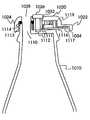
- FIG. 1is a side view of a bottle with self sealing cap assembly of the present invention
- FIG. 2is a top view of the cap assembly of the FIG. 1 embodiment
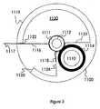
- FIG. 3is a top view of the cap base of the FIG. 1 embodiment
- FIG. 4is a perspective view of the cap assembly of FIGS. 2 and 3;
- FIG. 5is a top view of a preferred cap of the present invention.
- FIG. 6is a bottom view of the cap of FIG. 5;
- FIG. 7is a side view of an alternate embodiment of the cap
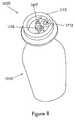
- FIG. 8is a perspective view of the preferred cap assembly and bottle portion for use with the cap of FIGS. 5 and 6;
- FIG. 9is a top view of the FIG. 8 cap assembly.
- the present inventionis a self sealing cap, particularly useful for bottles, containers, or other objects and most particularly useful for flowable confectionery bottles, such as disclosed in related pending applications entitled “Self-Sealing Cap” and “Soda Bottle Confectionery with Open Top,” incorporated herein by reference.
- FIG. 1is a side view of a bottle-shaped container 1010 of the present invention.
- FIGS. 1-4show one embodiment of a cap 1020 of the present invention.
- This embodimentcomprises a rotating cap 1020 on bottle 1010 or other object, as shown in the drawings.
- Cap 1020is part of a cap assembly.
- Cap 1020comprises a central aperture 1032 to fix cap 1020 to bottle 1010 .
- a screw 1026passes through central aperture 1032 .
- cap assemblyis integral with the bottle or other object.
- Cap 1020is rotatable about a central axis of screw 1026 , which is preferably, but optionally coaxial with the longitudinal axis of bottle 1010 .
- Rotatable cap 1020further comprises an off-center aperture 1028 that is positioned to allow for removal of material (e.g., a flowable liquid or confectionery) from bottle 1010 .
- Cap 1020optionally comprises a thumb wedge or protrusion 1022 and/or knurls 1024 , as shown in FIG. 2 .
- Knurls 1024mimic those of a traditional metal-capped or crimped soda bottle.
- Thumb wedge 1022 and knurls 1024facilitate rotation of cap 1020 .
- Thumb wedge 1022may also help a user grasp the bottle 1010 or other item to which cap 1020 is attached.
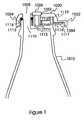
- FIG. 1A side, cross-sectional view of bottle 1010 , is shown in FIG. 1 .
- the cap basecomprises an aperture 1110 (preferably circular) for removal of material from bottle 1010 .
- Cap assemblycomprises an approximately 270 degree pie-shaped, recessed region 1120 for housing, in part, a spring 1116 .
- Cap 1020further comprises an aperture 1028 (preferably circular) therein.
- the userrotates cap 1020 to align off-center aperture 1028 with aperture 1110 in cap 1020 .
- alignment of the cap and bottle apertures 1028 , 1110is achieved, for example, by rotating cap 1020 in a counter-clockwise direction about the axis of screw 1026 .
- An o-ring 1114seated in an annular recess 1113 , is used to minimize undesirable migration of material from bottle 1010 .
- Annular recess 1113surrounds aperture 1110 of bottle 1010 .
- O-ring 1114is seated therein, forming a seal between cap 1020 and bottle 1010 .
- Screw 1026fixes cap 1020 to the cap base or bottle 1010 .
- Screw 1026passes through central aperture 1032 of cap 1020 and is secured in a cylindrical opening 1112 , which is defined by a cylindrical wall 1111 .
- Cylindrical wall 1111further serves as a post around which spiral-wound spring 1116 is seated.
- part of o-ring 1114extends over part of spring 1116 ; this arrangement helps to secure spring 1116 around cylindrical post 1111 .
- Spring 1116is positioned within the cap assembly to keep cap 1020 in a closed position; thus, force must be applied to cap 1020 to align cap aperture 1028 with bottle aperture 1110 , and thus allow the user to remove material from bottle 1010 .
- the term “self sealing cap”is used to describe the present invention. This self sealing is particularly important when a flowable confectionery is disposed within bottle 1010 .
- recessed region 1120comprises an approximately 270 degree pie-shape.
- Cylindrical opening 1112defined by cylindrical wall 1111 , is located at the center of this recessed region 1120 .
- Recessed region 1120comprises two internal walls that both start from a radius just greater than the radius of cylindrical wall 1111 . One of the walls is located at approximately 0 degrees 1123 (0 degree wall) and the other located at approximately 270 degrees 1124 (270 degree wall).
- Rim 1119surrounds recessed region 1120 , except for an approximately 45 degree cutout section 1125 .
- the cutout sectionis bounded/defined by two walls or stops, one at approximately 180 degrees 1122 (180 degree stop) and another at approximately 225 degrees 1125 (225 degree stop).
- spring 1116comprises a long end 1117 and a short end 1118 .
- Long end 1117extends from the spring's spiral core and is seated in a channel 1034 in the cap's thumb wedge 1022 . This end 1117 is biased directly or indirectly against the 180 degree stop 1122 of rim 1119 .
- Short end 1118also extends from the spiral core of spring 1116 and is biased against the 270 degree stop 1124 of recessed region 1120 .
- cap 1020rotation of cap 1020 to the 225 degree stop 1125 results in alignment of cap aperture 1028 and bottle aperture 1110 , in an open position.
- tension in spring 1116causes long end 1117 of spring to sweep in a clockwise direction towards the 180 degree stop 1122 to close cap 1020 , in a resting position.
- FIG. 4shows a perspective and sectional view of portions of the upper (turned over) and lower embodiment of the cap assembly of the present invention.
- FIGS. 5-9show a preferred embodiment of the present invention.
- FIG. 5is a top view and FIG. 6 is a bottom view of a preferred embodiment of cap assembly 1020 .
- cap 1021comprises a central aperture 1032 to fix cap assembly 1020 to bottle 1010 via screw 1026 (see FIG. 6 ).
- Screw 1026passes through central aperture 1032 of post 1617 .
- Cap 1021is rotatable about a central axis of screw 1026 , which is preferably, but optionally coaxial with the longitudinal axis of bottle.
- Rotatable cap 1021further comprises an off-center aperture 1028 that is positioned to allow for removal of material (e.g., a flowable liquid or confectionery) from bottle.
- materiale.g., a flowable liquid or confectionery
- Cap 1021preferably comprises thumb wedge or protrusion 1022 and/or knurls 1024 that facilitate rotation of cap 1021 .
- Thumb wedge 1022preferably comprises vertical element 1025 and horizontal element 1027 .
- Vertical element 1025as depicted in FIG. 5, encompasses end region 1200 of thumb wedge 1022 and provides an extra gripping surface to prevent finger slippage when a user movably engages thumb wedge 1022 .
- Horizontal element 1027is disposed between vertical element 1025 and cap 1021 and preferably comprises a substantially planar upper surface 1202 and curved outer sides 1204 for engagement of a user's thumb or other fingers.
- Cap 1021in this preferred embodiment, additionally comprises post 1136 which extends from under side of cap 1021 to effectively provide tension to spring 1116 (see FIG. 8) and rotate and bias cap 1021 to an open or engaged position.
- an alternate embodiment of cap assembly 1020comprises elongated outer cylindrical wall 1023 of cap 1021 .
- Outer cylindrical wall 1023additionally comprises knurls 1024 and/or a thumb wedge or protrusion 1022 .
- thumb wedge 1022facilitates rotation of cap 1021 .
- Thumb wedge 1022as depicted in FIG. 7 comprises a vertical element 1210 extending from cylindrical wall 1023 having the same or substantially the same vertical height as cylindrical wall 1023 .
- Horizontal element 1212additionally extends from wall 1023 at a point 1213 at a distance approximately 1 ⁇ 6 of the circumference of cylindrical wall 1023 .
- Horizontal element 1212comprises a substantially planar surface with outer curving side 1214 extending to intersection 1216 of outer side 1218 and lower side 1220 of vertical element 1210 .
- Horizontal element 1212may serve as a thumb slide or as a strengthening element for vertical element 1210 , depending on its orientation to the rotatable end of the spring in the cap assembly. While a substantially rectangular wedge shape has been depicted and described for vertical element 1210 , other wedge shapes are within the purview of the invention. Additionally, horizontal element 1212 may extend from points further from and closer to vertical element 1210 , and may comprise different outer side configurations.
- FIG. 8is a perspective view showing bottle 1010 with preferred cap assembly 1020 of the present invention.
- opening 1712allows for passage of confectionery from bottle 1010 through opening 1712 , then through aperture 1028 of cap 1021 , when cap 1021 is engaged (when the user rotates cap 1021 about central axis of screw 1026 ).
- the userneeds to turn bottle 1010 upside down or at a downward angle to allow confectionery to flow out of opening 1712 and aperture 1028 .
- aperture 1028does not align with opening 1712 , opening 1712 and aperture 1028 are thereby closed, and the confectionery remains in bottle 1010 , even when tilted or inverted.
- FIG. 9is a top view of cap assembly 1020 disposed above bottle 1010 (see FIG. 7 ).
- cap base 1113provides for rotation of spring 1116 and cap 1021 (see FIGS. 5 and 6 ).
- Spring 1116spirals about central post 1617 , is fixed in position on one end between two stops 1123 and 1124 and rotates between two stops 1122 (closed or disengaged position) and 1125 (open or engaged position).
- Cap base 1113has a 360 degree reference system having 0 degrees and 180 degrees defined along a horizontal axis from right to left and 90 degrees and 270 degrees defined along a vertical axis from to top to bottom.
- Recessed region 1120comprises the entire 360 degrees, with the exception of several protruding stops 1122 , 1123 , 1124 and 1125 .
- Cylindrical opening 1712defined by cylindrical wall 1111 , is intersected by the 0-180 degree axis and is located adjacent to a side wall of cap base 1113 of recessed region 1120 .
- Recessed region 1120additionally comprises four vertically protruding stops 1122 , 1123 , 1124 and 1125 .
- One stop 1123is located at approximately 225 degrees
- another stop 1124is located adjacent to stop 1124 at approximately 250 degrees. These two stops 1123 and 1124 extend at an axis slightly off radius and directed toward opening 1712 .
- Stops 1123 and 1124lie in a side-by-side arrangement comprising space 1126 .
- Space 1126is sufficient for receipt of straight end 1128 of spring 1116 extending from a lowerend of its spiral core.
- Curved end 1128extends from a substantially straight extension 1130 from the spiral core.
- Straight end of spring 1128is disposed within space between stops 1123 and 1124 and does not move or only slightly moves.
- Stop 1125is positioned at approximately 110 degrees. Stop 1122 is positioned at approximately 45 degrees. Curved end 1129 of spring 1116 is disposed between and rotates between stops 1125 and 1122 . Curved end 1129 of spring 1116 is engaged by cap post 1136 (see FIG. 6) for this rotation.
- cap 1021When cap 1021 is in its resting position (closed position), curved spring end 1129 rests or stops at stop 1122 and aperture 1028 of cap 1021 does not align with opening 1712 of cap base 1113 . In this position, confectionery cannot flow out of bottle 1010 .
- spring curved end 1129rotates to stop 1125 by engagement with post 1136 , thereby aligning opening 1712 and aperture 1028 so confectionery can flow out of bottle 1010 .
- spring 1116In the open position, spring 1116 is in tension, so that the user must continue to use force (e.g., by thumb wedge 1022 ) to keep this rotation and alignment.
Landscapes
- Engineering & Computer Science (AREA)
- Life Sciences & Earth Sciences (AREA)
- Chemical & Material Sciences (AREA)
- Food Science & Technology (AREA)
- Polymers & Plastics (AREA)
- Mechanical Engineering (AREA)
- Closures For Containers (AREA)
Abstract
Description
Claims (22)
Priority Applications (2)
| Application Number | Priority Date | Filing Date | Title |
|---|---|---|---|
| US10/072,269US6651833B2 (en) | 2001-06-04 | 2002-02-05 | Self sealing cap with spring and post |
| PCT/US2002/017877WO2002098764A1 (en) | 2001-06-04 | 2002-06-04 | Dippable hard candy enclosed confectionery and self-sealing cap |
Applications Claiming Priority (2)
| Application Number | Priority Date | Filing Date | Title |
|---|---|---|---|
| US09/874,448US6561371B2 (en) | 2001-06-04 | 2001-06-04 | Self sealing cap |
| US10/072,269US6651833B2 (en) | 2001-06-04 | 2002-02-05 | Self sealing cap with spring and post |
Related Parent Applications (1)
| Application Number | Title | Priority Date | Filing Date |
|---|---|---|---|
| US09/874,448Continuation-In-PartUS6561371B2 (en) | 2001-06-04 | 2001-06-04 | Self sealing cap |
Publications (2)
| Publication Number | Publication Date |
|---|---|
| US20020179562A1 US20020179562A1 (en) | 2002-12-05 |
| US6651833B2true US6651833B2 (en) | 2003-11-25 |
Family
ID=46278801
Family Applications (1)
| Application Number | Title | Priority Date | Filing Date |
|---|---|---|---|
| US10/072,269Expired - Fee RelatedUS6651833B2 (en) | 2001-06-04 | 2002-02-05 | Self sealing cap with spring and post |
Country Status (1)
| Country | Link |
|---|---|
| US (1) | US6651833B2 (en) |
Cited By (13)
| Publication number | Priority date | Publication date | Assignee | Title |
|---|---|---|---|---|
| US20040232160A1 (en)* | 2003-05-22 | 2004-11-25 | Kotobuki & Co., Ltd. | Container |
| US20050150889A1 (en)* | 2004-01-13 | 2005-07-14 | Perra Antonio G. | Device for sealing foodstuff containers and foodstuff container provided with such a device |
| US8844761B2 (en) | 2012-08-10 | 2014-09-30 | Daniel A. Zabaleta | Resealable beverage containers and methods of making same |
| US8985371B2 (en) | 2012-08-10 | 2015-03-24 | Daniel A. Zabaleta | Resealable beverage containers and methods of making same |
| US9637269B1 (en) | 2012-08-10 | 2017-05-02 | Daniel A. Zabaleta | Resealable container lid and accessories including methods of manufacturing and use |
| USD795693S1 (en) | 2012-08-10 | 2017-08-29 | Daniel A Zabeleta | Axially oriented peripheral sidewalled beverage container lid |
| USD828753S1 (en) | 2012-08-10 | 2018-09-18 | Daniel A Zabaleta | Axially oriented peripheral sidewalled beverage container lid |
| US10968010B1 (en) | 2012-08-10 | 2021-04-06 | Daniel A Zabaleta | Resealable container lid and accessories including methods of manufacture and use |
| US11767152B2 (en) | 2021-06-29 | 2023-09-26 | Iv Thought Products And Design Corp. | Re-sealing vacuum package receptacle |
| US11952164B1 (en) | 2012-08-10 | 2024-04-09 | Powercan Holding, Llc | Resealable container lid and accessories including methods of manufacture and use |
| USD1033215S1 (en) | 2012-08-10 | 2024-07-02 | Daniel A. Zabaleta | Container lid comprising frustum shaped sidewall and seaming chuck receiving radius |
| US12365511B1 (en) | 2012-08-10 | 2025-07-22 | Daniel A Zabaleta | Sealing cap having tamper evidence ring for sealing resealable container and method of use |
| US12384594B2 (en) | 2021-04-05 | 2025-08-12 | Daniel A. Zabaleta | Threaded container components having frustum shaped surfaces enabling nesting |
Families Citing this family (2)
| Publication number | Priority date | Publication date | Assignee | Title |
|---|---|---|---|---|
| TW201014776A (en)* | 2008-10-07 | 2010-04-16 | Free Free Ind Corp | Sealing lid |
| TWI418507B (en)* | 2011-07-13 | 2013-12-11 | Her Chian Acrylic Co Ltd | Cover of seal container with its inner wall being smoothly connected with inner wall of jar body of the seal container |
Citations (31)
| Publication number | Priority date | Publication date | Assignee | Title |
|---|---|---|---|---|
| US781332A (en) | 1904-10-11 | 1905-01-31 | George Demacakos | Bottle-cap. |
| US793757A (en) | 1904-09-22 | 1905-07-04 | A V Oldham | Closure for bottles or other containers. |
| US1021452A (en) | 1911-04-22 | 1912-03-26 | James F Craven | Receptacle for containing and discharging semisolid and pasty substances. |
| US1404883A (en) | 1920-06-01 | 1922-01-31 | Alexander W Murray | Dispensing can |
| US1612719A (en) | 1925-08-31 | 1926-12-28 | Haddad Joseph Elies | Bottle cover |
| US1963050A (en) | 1931-02-20 | 1934-06-12 | Alan H Graham | Bottle cap |
| US2018050A (en) | 1933-05-30 | 1935-10-22 | Bentley Bede John Francis | Sifter cap for powder containers |
| US2533915A (en) | 1945-05-07 | 1950-12-12 | Chester A Brooks | Rotatable closure structure having yieldable locking means |
| US2636649A (en) | 1950-04-11 | 1953-04-28 | Corriveau Clarence Philip | Closure for dispensing containers |
| US2824010A (en) | 1955-07-29 | 1958-02-18 | Carl G Pedersen | Flavor-containing milk container top |
| US3355067A (en) | 1967-01-03 | 1967-11-28 | Espinal Martin | Recording pill dispenser |
| US3410462A (en) | 1967-04-18 | 1968-11-12 | Monsanto Co | Spring biased dispensing closure |
| US3413128A (en) | 1967-05-08 | 1968-11-26 | Preferida Inc | Bottle |
| US4914748A (en) | 1988-08-30 | 1990-04-03 | Schlotter Iv William K | In combination, a novelty flashlight and piece of candy for illumination |
| US5027986A (en) | 1989-06-09 | 1991-07-02 | Heinzel Irving Charles | Actuating valve for aerosol foam product |
| US5209692A (en) | 1992-01-08 | 1993-05-11 | Coleman Thomas J | Combination, a novelty toy and a candy holding device |
| US5370884A (en) | 1994-02-18 | 1994-12-06 | B.A.A.T. Enterprises Inc. | Combination sucker and edible powder |
| US5386909A (en) | 1993-11-01 | 1995-02-07 | Spector; Donald | Display package for shaped candy pieces |
| US5391107A (en) | 1993-09-17 | 1995-02-21 | B.A.A.T Enterprises Inc. | Device for making a candy sucker jiggle |
| US5540353A (en) | 1995-03-23 | 1996-07-30 | Coleman; Thomas J. | Candy container and dispenser |
| US5615941A (en) | 1996-05-20 | 1997-04-01 | Shecter; Jules | Illuminated dual lollipop holder and storage device |
| US5758802A (en) | 1996-09-06 | 1998-06-02 | Dart Industries Inc. | Icing set |
| US5820437A (en) | 1996-07-23 | 1998-10-13 | Coleman; Thomas J. | Wacky pop noise maker |
| US5853093A (en) | 1997-05-22 | 1998-12-29 | Neiger; Eliezer | Reclosable, two-part cap assembly for soda bottles |
| US5921425A (en) | 1997-07-02 | 1999-07-13 | Markey; Victor S. | Container cap with spring loaded cover |
| US5993870A (en) | 1998-01-28 | 1999-11-30 | Oddzon/Cap Toys, Inc. | Device for storing and coating a confectionery product having a handle |
| WO2000019803A2 (en) | 1998-12-02 | 2000-04-13 | Impact Confections, Inc. | Paint set confectionery |
| US6136352A (en) | 1999-07-20 | 2000-10-24 | The Topps Company, Inc. | Sanitary novelty candy product |
| US6159492A (en) | 1999-03-04 | 2000-12-12 | Manzone; Cheryl | Drug storage and delivery system containing a medicated lollipop |
| USD436549S1 (en) | 1995-08-21 | 2001-01-23 | Sidney H. Kosann | Soda bottle whistle |
| US6332551B1 (en) | 1998-11-10 | 2001-12-25 | Stephan Copeland | Self-sealing container |
- 2002
- 2002-02-05USUS10/072,269patent/US6651833B2/ennot_activeExpired - Fee Related
Patent Citations (31)
| Publication number | Priority date | Publication date | Assignee | Title |
|---|---|---|---|---|
| US793757A (en) | 1904-09-22 | 1905-07-04 | A V Oldham | Closure for bottles or other containers. |
| US781332A (en) | 1904-10-11 | 1905-01-31 | George Demacakos | Bottle-cap. |
| US1021452A (en) | 1911-04-22 | 1912-03-26 | James F Craven | Receptacle for containing and discharging semisolid and pasty substances. |
| US1404883A (en) | 1920-06-01 | 1922-01-31 | Alexander W Murray | Dispensing can |
| US1612719A (en) | 1925-08-31 | 1926-12-28 | Haddad Joseph Elies | Bottle cover |
| US1963050A (en) | 1931-02-20 | 1934-06-12 | Alan H Graham | Bottle cap |
| US2018050A (en) | 1933-05-30 | 1935-10-22 | Bentley Bede John Francis | Sifter cap for powder containers |
| US2533915A (en) | 1945-05-07 | 1950-12-12 | Chester A Brooks | Rotatable closure structure having yieldable locking means |
| US2636649A (en) | 1950-04-11 | 1953-04-28 | Corriveau Clarence Philip | Closure for dispensing containers |
| US2824010A (en) | 1955-07-29 | 1958-02-18 | Carl G Pedersen | Flavor-containing milk container top |
| US3355067A (en) | 1967-01-03 | 1967-11-28 | Espinal Martin | Recording pill dispenser |
| US3410462A (en) | 1967-04-18 | 1968-11-12 | Monsanto Co | Spring biased dispensing closure |
| US3413128A (en) | 1967-05-08 | 1968-11-26 | Preferida Inc | Bottle |
| US4914748A (en) | 1988-08-30 | 1990-04-03 | Schlotter Iv William K | In combination, a novelty flashlight and piece of candy for illumination |
| US5027986A (en) | 1989-06-09 | 1991-07-02 | Heinzel Irving Charles | Actuating valve for aerosol foam product |
| US5209692A (en) | 1992-01-08 | 1993-05-11 | Coleman Thomas J | Combination, a novelty toy and a candy holding device |
| US5391107A (en) | 1993-09-17 | 1995-02-21 | B.A.A.T Enterprises Inc. | Device for making a candy sucker jiggle |
| US5386909A (en) | 1993-11-01 | 1995-02-07 | Spector; Donald | Display package for shaped candy pieces |
| US5370884A (en) | 1994-02-18 | 1994-12-06 | B.A.A.T. Enterprises Inc. | Combination sucker and edible powder |
| US5540353A (en) | 1995-03-23 | 1996-07-30 | Coleman; Thomas J. | Candy container and dispenser |
| USD436549S1 (en) | 1995-08-21 | 2001-01-23 | Sidney H. Kosann | Soda bottle whistle |
| US5615941A (en) | 1996-05-20 | 1997-04-01 | Shecter; Jules | Illuminated dual lollipop holder and storage device |
| US5820437A (en) | 1996-07-23 | 1998-10-13 | Coleman; Thomas J. | Wacky pop noise maker |
| US5758802A (en) | 1996-09-06 | 1998-06-02 | Dart Industries Inc. | Icing set |
| US5853093A (en) | 1997-05-22 | 1998-12-29 | Neiger; Eliezer | Reclosable, two-part cap assembly for soda bottles |
| US5921425A (en) | 1997-07-02 | 1999-07-13 | Markey; Victor S. | Container cap with spring loaded cover |
| US5993870A (en) | 1998-01-28 | 1999-11-30 | Oddzon/Cap Toys, Inc. | Device for storing and coating a confectionery product having a handle |
| US6332551B1 (en) | 1998-11-10 | 2001-12-25 | Stephan Copeland | Self-sealing container |
| WO2000019803A2 (en) | 1998-12-02 | 2000-04-13 | Impact Confections, Inc. | Paint set confectionery |
| US6159492A (en) | 1999-03-04 | 2000-12-12 | Manzone; Cheryl | Drug storage and delivery system containing a medicated lollipop |
| US6136352A (en) | 1999-07-20 | 2000-10-24 | The Topps Company, Inc. | Sanitary novelty candy product |
Cited By (19)
| Publication number | Priority date | Publication date | Assignee | Title |
|---|---|---|---|---|
| US20040232160A1 (en)* | 2003-05-22 | 2004-11-25 | Kotobuki & Co., Ltd. | Container |
| US7137527B2 (en)* | 2003-05-22 | 2006-11-21 | Kotobuki & Co., Ltd. | Container |
| US20050150889A1 (en)* | 2004-01-13 | 2005-07-14 | Perra Antonio G. | Device for sealing foodstuff containers and foodstuff container provided with such a device |
| US7823740B2 (en)* | 2004-01-13 | 2010-11-02 | Bound2B B.V. | Device for sealing foodstuff containers and foodstuff container provided with such a device |
| USD795693S1 (en) | 2012-08-10 | 2017-08-29 | Daniel A Zabeleta | Axially oriented peripheral sidewalled beverage container lid |
| US10968010B1 (en) | 2012-08-10 | 2021-04-06 | Daniel A Zabaleta | Resealable container lid and accessories including methods of manufacture and use |
| US9272819B1 (en) | 2012-08-10 | 2016-03-01 | Daniel A. Zabaleta | Resealable container lid including methods of manufacture and use |
| US9637269B1 (en) | 2012-08-10 | 2017-05-02 | Daniel A. Zabaleta | Resealable container lid and accessories including methods of manufacturing and use |
| US8844761B2 (en) | 2012-08-10 | 2014-09-30 | Daniel A. Zabaleta | Resealable beverage containers and methods of making same |
| USD828753S1 (en) | 2012-08-10 | 2018-09-18 | Daniel A Zabaleta | Axially oriented peripheral sidewalled beverage container lid |
| US10427832B1 (en) | 2012-08-10 | 2019-10-01 | Daniel A Zabaleta | Resealable container lid assembly and accessories including methods of manufacture and use |
| US8985371B2 (en) | 2012-08-10 | 2015-03-24 | Daniel A. Zabaleta | Resealable beverage containers and methods of making same |
| US12365511B1 (en) | 2012-08-10 | 2025-07-22 | Daniel A Zabaleta | Sealing cap having tamper evidence ring for sealing resealable container and method of use |
| US11952164B1 (en) | 2012-08-10 | 2024-04-09 | Powercan Holding, Llc | Resealable container lid and accessories including methods of manufacture and use |
| USD1033215S1 (en) | 2012-08-10 | 2024-07-02 | Daniel A. Zabaleta | Container lid comprising frustum shaped sidewall and seaming chuck receiving radius |
| USD1033217S1 (en) | 2012-08-10 | 2024-07-02 | Daniel A. Zabaleta | Container lid having non-congruent frustum shaped sidewall segments enabling nesting |
| USD1033216S1 (en) | 2012-08-10 | 2024-07-02 | Daniel A. Zabaleta | Container cap having frustum shaped sidewall segment enabling nesting |
| US12384594B2 (en) | 2021-04-05 | 2025-08-12 | Daniel A. Zabaleta | Threaded container components having frustum shaped surfaces enabling nesting |
| US11767152B2 (en) | 2021-06-29 | 2023-09-26 | Iv Thought Products And Design Corp. | Re-sealing vacuum package receptacle |
Also Published As
| Publication number | Publication date |
|---|---|
| US20020179562A1 (en) | 2002-12-05 |
Similar Documents
| Publication | Publication Date | Title |
|---|---|---|
| US6651833B2 (en) | Self sealing cap with spring and post | |
| US11577892B2 (en) | Lid assembly with a rotary trigger for seal assembly and beverage container comprising the same | |
| US4485963A (en) | Cup with pivoting straw | |
| KR920008337B1 (en) | Vessel with pressure-opening lid | |
| KR100270895B1 (en) | Container with two position handle | |
| US7845525B2 (en) | Carbonated drink closure and dispensing device | |
| US6050434A (en) | Container closure with double-axis resiliently-biasing web-hinge structure | |
| US6216903B1 (en) | Bi-directional operating closure for a liquid container | |
| AU607375B2 (en) | Dispensing container closure | |
| US7040499B1 (en) | Container with primary closure and a secondary closure | |
| JPH05262365A (en) | Dispensing closure | |
| US20200216232A1 (en) | Container lid with rotatable sipper and flexible handle | |
| CA2688803A1 (en) | Pitcher lid with spout gate and stirring mechanism | |
| CN222474973U (en) | Container cover and beverage container comprising same | |
| RU2182878C1 (en) | Hybrid container for drinks (versions) | |
| US6561371B2 (en) | Self sealing cap | |
| US7051896B2 (en) | Opening assembly | |
| US20040259235A1 (en) | Beverage can with a recloseable opening | |
| AU2002225199A1 (en) | Opening assembly | |
| WO2005105612A1 (en) | Plastic vessel | |
| EP0330741B1 (en) | Pouring cap in particular for liquids | |
| JP2004175359A (en) | Drink container | |
| KR200376968Y1 (en) | Airtight vessel | |
| KR200308955Y1 (en) | for drink case a cap carry and open and shut simple | |
| KR20220138690A (en) | Beverage container |
Legal Events
| Date | Code | Title | Description |
|---|---|---|---|
| AS | Assignment | Owner name:IMPACT CONFECTIONS, INC., COLORADO Free format text:ASSIGNMENT OF ASSIGNORS INTEREST;ASSIGNOR:SCIARINI, GERALD A.;REEL/FRAME:012853/0853 Effective date:20020403 | |
| REMI | Maintenance fee reminder mailed | ||
| FPAY | Fee payment | Year of fee payment:4 | |
| SULP | Surcharge for late payment | ||
| AS | Assignment | Owner name:MERRILL LYNCH CAPITAL, A DIVISION OF MERRILL LYNCH Free format text:SECURITY AGREEMENT;ASSIGNOR:IMPACT CONFECTIONS, INC.;REEL/FRAME:020371/0574 Effective date:20080115 Owner name:LEGG MASON SBIC MEZZANINE FUND, L.P., A DELAWARE L Free format text:PATENT SECURITY AGREEMENT;ASSIGNOR:IMPACT CONFECTIONS, INC., A NEW MEXICO CORPORATION;REEL/FRAME:020385/0256 Effective date:20080115 | |
| REMI | Maintenance fee reminder mailed | ||
| LAPS | Lapse for failure to pay maintenance fees | ||
| STCH | Information on status: patent discontinuation | Free format text:PATENT EXPIRED DUE TO NONPAYMENT OF MAINTENANCE FEES UNDER 37 CFR 1.362 | |
| FP | Lapsed due to failure to pay maintenance fee | Effective date:20111125 | |
| AS | Assignment | Owner name:IMPACT CONFECTIONS, INC., MINNESOTA Free format text:RELEASE BY SECURED PARTY;ASSIGNOR:GE BUSINESS FINANCIAL SERVICES INC.;REEL/FRAME:034142/0660 Effective date:20141110 Owner name:IMPACT CONFECTIONS, INC., MINNESOTA Free format text:ASSIGNMENT OF ASSIGNORS INTEREST;ASSIGNOR:LEGG MASON SBIC MEZZANINE FUND, L.P.;REEL/FRAME:034142/0567 Effective date:20141110 Owner name:IMPACT CONFECTIONS, INC., MINNESOTA Free format text:RELEASE BY SECURED PARTY;ASSIGNOR:LEGG MASON SBIC MEZZANINE FUND, L.P.;REEL/FRAME:034142/0603 Effective date:20141110 Owner name:U.S. BANK NATIONAL ASSOCIATION, MINNESOTA Free format text:SECURITY INTEREST;ASSIGNOR:IMPACT CONFECTIONS, INC.;REEL/FRAME:034142/0685 Effective date:20141110 | |
| AS | Assignment | Owner name:IMPACT CONFECTIONS, INC., WISCONSIN Free format text:RELEASE BY SECURED PARTY;ASSIGNOR:U.S. BANK NATIONAL ASSOCIATION;REEL/FRAME:051872/0805 Effective date:20191211 | |
| AS | Assignment | Owner name:BMO BANK N.A., AS ADMINISTRATIVE AGENT, ILLINOIS Free format text:SECURITY INTEREST;ASSIGNOR:IMPACT CONFECTIONS, INC.;REEL/FRAME:069446/0238 Effective date:20241127 |