US6650928B1 - Color parametric and composite maps for CT perfusion - Google Patents
Color parametric and composite maps for CT perfusionDownload PDFInfo
- Publication number
- US6650928B1 US6650928B1US09/723,128US72312800AUS6650928B1US 6650928 B1US6650928 B1US 6650928B1US 72312800 AUS72312800 AUS 72312800AUS 6650928 B1US6650928 B1US 6650928B1
- Authority
- US
- United States
- Prior art keywords
- color
- mapping
- image
- accordance
- images
- Prior art date
- Legal status (The legal status is an assumption and is not a legal conclusion. Google has not performed a legal analysis and makes no representation as to the accuracy of the status listed.)
- Expired - Lifetime, expires
Links
- 230000010412perfusionEffects0.000titleclaimsabstractdescription33
- 239000002131composite materialSubstances0.000titledescription5
- 238000013507mappingMethods0.000claimsabstractdescription48
- 238000000034methodMethods0.000claimsabstractdescription24
- 238000013170computed tomography imagingMethods0.000claimsabstractdescription19
- 238000003384imaging methodMethods0.000claimsabstractdescription17
- 238000004458analytical methodMethods0.000claimsabstractdescription5
- XEEYBQQBJWHFJM-UHFFFAOYSA-NIronChemical compound[Fe]XEEYBQQBJWHFJM-UHFFFAOYSA-N0.000claimsdescription14
- 230000005855radiationEffects0.000claimsdescription12
- 239000008280bloodSubstances0.000claimsdescription8
- 210000004369bloodAnatomy0.000claimsdescription8
- 229910052742ironInorganic materials0.000claimsdescription7
- 229910052716thalliumInorganic materials0.000claimsdescription7
- BKVIYDNLLOSFOA-UHFFFAOYSA-NthalliumChemical compound[Tl]BKVIYDNLLOSFOA-UHFFFAOYSA-N0.000claimsdescription7
- 230000017531blood circulationEffects0.000claimsdescription6
- 238000005259measurementMethods0.000claimsdescription5
- 208000028867ischemiaDiseases0.000claimsdescription3
- 239000003086colorantSubstances0.000description9
- 239000000126substanceSubstances0.000description4
- 238000002591computed tomographyMethods0.000description3
- 238000009206nuclear medicineMethods0.000description3
- 230000002238attenuated effectEffects0.000description2
- 210000004556brainAnatomy0.000description2
- ZCYVEMRRCGMTRW-UHFFFAOYSA-N7553-56-2Chemical compound[I]ZCYVEMRRCGMTRW-UHFFFAOYSA-N0.000description1
- 210000003484anatomyAnatomy0.000description1
- 230000005540biological transmissionEffects0.000description1
- 210000004204blood vesselAnatomy0.000description1
- 230000001419dependent effectEffects0.000description1
- 238000001514detection methodMethods0.000description1
- 238000010586diagramMethods0.000description1
- 230000002708enhancing effectEffects0.000description1
- 235000021384green leafy vegetablesNutrition0.000description1
- 238000002347injectionMethods0.000description1
- 239000007924injectionSubstances0.000description1
- 239000011630iodineSubstances0.000description1
- 229910052740iodineInorganic materials0.000description1
- 230000000302ischemic effectEffects0.000description1
- 238000012986modificationMethods0.000description1
- 230000004048modificationEffects0.000description1
- 210000000056organAnatomy0.000description1
- 238000002600positron emission tomographyMethods0.000description1
- 238000012805post-processingMethods0.000description1
- 238000007781pre-processingMethods0.000description1
- 238000004540process dynamicMethods0.000description1
- 238000012545processingMethods0.000description1
- 230000011218segmentationEffects0.000description1
- 238000001228spectrumMethods0.000description1
- 230000000007visual effectEffects0.000description1
Images


Classifications
- A—HUMAN NECESSITIES
- A61—MEDICAL OR VETERINARY SCIENCE; HYGIENE
- A61B—DIAGNOSIS; SURGERY; IDENTIFICATION
- A61B6/00—Apparatus or devices for radiation diagnosis; Apparatus or devices for radiation diagnosis combined with radiation therapy equipment
- A61B6/50—Apparatus or devices for radiation diagnosis; Apparatus or devices for radiation diagnosis combined with radiation therapy equipment specially adapted for specific body parts; specially adapted for specific clinical applications
- A61B6/504—Apparatus or devices for radiation diagnosis; Apparatus or devices for radiation diagnosis combined with radiation therapy equipment specially adapted for specific body parts; specially adapted for specific clinical applications for diagnosis of blood vessels, e.g. by angiography
- A—HUMAN NECESSITIES
- A61—MEDICAL OR VETERINARY SCIENCE; HYGIENE
- A61B—DIAGNOSIS; SURGERY; IDENTIFICATION
- A61B6/00—Apparatus or devices for radiation diagnosis; Apparatus or devices for radiation diagnosis combined with radiation therapy equipment
- A61B6/02—Arrangements for diagnosis sequentially in different planes; Stereoscopic radiation diagnosis
- A61B6/03—Computed tomography [CT]
- A61B6/032—Transmission computed tomography [CT]
- A—HUMAN NECESSITIES
- A61—MEDICAL OR VETERINARY SCIENCE; HYGIENE
- A61B—DIAGNOSIS; SURGERY; IDENTIFICATION
- A61B6/00—Apparatus or devices for radiation diagnosis; Apparatus or devices for radiation diagnosis combined with radiation therapy equipment
- A61B6/50—Apparatus or devices for radiation diagnosis; Apparatus or devices for radiation diagnosis combined with radiation therapy equipment specially adapted for specific body parts; specially adapted for specific clinical applications
- A61B6/507—Apparatus or devices for radiation diagnosis; Apparatus or devices for radiation diagnosis combined with radiation therapy equipment specially adapted for specific body parts; specially adapted for specific clinical applications for determination of haemodynamic parameters, e.g. perfusion CT
- A—HUMAN NECESSITIES
- A61—MEDICAL OR VETERINARY SCIENCE; HYGIENE
- A61B—DIAGNOSIS; SURGERY; IDENTIFICATION
- A61B6/00—Apparatus or devices for radiation diagnosis; Apparatus or devices for radiation diagnosis combined with radiation therapy equipment
- A61B6/48—Diagnostic techniques
- A61B6/481—Diagnostic techniques involving the use of contrast agents
- Y—GENERAL TAGGING OF NEW TECHNOLOGICAL DEVELOPMENTS; GENERAL TAGGING OF CROSS-SECTIONAL TECHNOLOGIES SPANNING OVER SEVERAL SECTIONS OF THE IPC; TECHNICAL SUBJECTS COVERED BY FORMER USPC CROSS-REFERENCE ART COLLECTIONS [XRACs] AND DIGESTS
- Y10—TECHNICAL SUBJECTS COVERED BY FORMER USPC
- Y10S—TECHNICAL SUBJECTS COVERED BY FORMER USPC CROSS-REFERENCE ART COLLECTIONS [XRACs] AND DIGESTS
- Y10S128/00—Surgery
- Y10S128/92—Computer assisted medical diagnostics
- Y10S128/922—Computer assisted medical diagnostics including image analysis
Definitions
- This inventionrelates generally to methods and apparatus for facilitating computed tomographic (CT) image assessment, and more particularly to methods and apparatus for enhancing functional data on CT images.
- CTcomputed tomographic
- an x-ray sourceprojects a fan-shaped beam which is collimated to lie within an X-Y plane of a Cartesian coordinate system and generally referred to as the “imaging plane”.
- the x-ray beampasses through the object being imaged, such as a patient.
- the beamafter being attenuated by the object, impinges upon an array of radiation detectors.
- the intensity of the attenuated beam radiation received at the detector arrayis dependent upon the attenuation of the x-ray beam by the object.
- Each detector element of the arrayproduces a separate electrical signal that is a measurement of the beam attenuation at the detector location.
- the attenuation measurements from all the detectorsare acquired separately to produce a transmission profile.
- X-ray sourcestypically include x-ray tubes, which emit the x-ray beam at a focal spot.
- X-ray detectorstypically include a collimator for collimating x-ray beams received at the detector, a scintillator adjacent the collimator, and photodetectors adjacent the scintillator.
- Computed tomographyis an anatomical imaging modality, but recently there have been advances that give some functional imaging capabilities to CT.
- CTComputed tomography
- one known image software package for CT perfusionprovides facilities for a user to process dynamic image data and to generate functional information and images that include functional image data relating to perfusion.
- the softwareuses changes in image intensity as a function of time to generate the information and the images.
- CThas classically been a grayscale-only modality, and it is difficult to assess differences in data on such images.
- Imaging modalitiessuch as nuclear medicine and positron emission tomography (PET)
- PETpositron emission tomography
- Coloris often utilized with these modalities to give better discrimination than grayscale maps in the assessment of the displayed data.
- CT Perfusionis a functional imaging software and is similar to perfusion packages in nuclear medicine or MR but is a unique use for CT.
- One embodiment of the present inventionis therefore a method for facilitating the analysis of computed tomographic (CT) images.
- the methodincludes steps of: acquiring attenuation data of a patient using a CT imaging system; reconstructing images of the patient using the acquired attenuation data; mapping intensity data from at least one reconstructed image into a color image using a color mapping indicative of physiological thresholds; and displaying the color image.
- Embodiments of the present inventionfacilitate the assessment of images and differences between images for functional image data and for perfusion-related imaging data.
- FIG. 1is a pictorial view of a CT imaging system.
- FIG. 2is a block schematic diagram of the system illustrated in FIG. 1 .
- FIG. 3is a representation of an anteroposterior projection of a head of a patient showing a potential location of a blockage.
- FIG. 4is a representation of a CT anatomical image
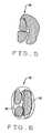
- FIG. 5is a representation of a CT parametric image.
- FIG. 6is a representation of a CT parametric image overlaid over a CT anatomical image.
- FIG. 7is a representation of the combination of several composite images or slices into a 3D (three dimensional) image showing 3D functional data.
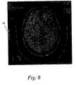
- FIG. 8is a sample three-color parametric image.
- FIG. 9is a sample rainbow colored composite image.
- a computed tomography (CT) imaging system 10is shown as including a gantry 12 representative of a “third generation” CT scanner.
- Gantry 12has an x-ray source 14 that projects a beam of x-rays 16 toward a detector array 18 on the opposite side of gantry 12 .
- Detector array 18is formed by detector elements 20 which together sense the projected x-rays that pass through an object, such as a medical patient 22 .
- Each detector element 20produces an electrical signal that represents the intensity of an impinging x-ray beam and hence the attenuation of the beam as it passes through object or patient 22 .
- detector elements 20are arranged in one row so that projection data corresponding to a single image slice is acquired during a scan. In another embodiment, detector elements 20 are arranged in a plurality of parallel rows, so that projection data corresponding to a plurality of parallel slices can be acquired simultaneously during a scan.
- Control mechanism 26includes an x-ray controller 28 that provides power and timing signals to x-ray source 14 and a gantry motor controller 30 that controls the rotational speed and position of gantry 12 .
- a data acquisition system (DAS) 32 in control mechanism 26samples analog data from detector elements 20 and converts the data to digital signals for subsequent processing.
- An image reconstructor 34receives sampled and digitized x-ray data from DAS 32 and performs high speed image reconstruction. The reconstructed image is applied as an input to a computer 36 which stores the image in a mass storage device 38 .
- DASdata acquisition system
- Computer 36also receives commands and scanning parameters from an operator via console 40 that has a keyboard.
- An associated cathode ray tube display 42allows the operator to observe the reconstructed image and other data from computer 36 .
- the operator supplied commands and parametersare used by computer 36 to provide control signals and information to DAS 32 , x-ray controller 28 and gantry motor controller 30 .
- computer 36operates a table motor controller 44 which controls a motorized table 46 to position patient 22 in gantry 12 . Particularly, table 46 moves portions of patient 22 through gantry opening 48 .
- blood flow parameters of an organ of patient 22are measured by injecting a substance (for example, one containing iodine) into patient 22 that produces a contrasting appearance on CT images.
- a substancefor example, one containing iodine
- blood flow, blood volume, and mean transit timecan be measured by examining the perfusion of the contrasting substance, which allows blockages 52 to be recognized.
- a blockage in one embodiment of the inventioncauses a change in color because of the change in volume, flow, or mean transit time.
- maps with different color schemesare used for CT perfusion parametric images to facilitate their assessment.
- display 42is a color display
- software in computer 36uses a mapping of intensities to color to enhance images for analysis.
- the softwarecompares reconstructed images denoting the same region at different times, the software denote differences in measurements, as a function of time, of quantities such as blood flow, blood volume, and mean transit time for blood containing the injected substance to move through a cell.
- intensities or intensity differencesare mapped onto a set of colors by the software and the images are displayed on color display 42 .
- One or more types of color mapsare available for use in one embodiment.
- suitable mapsinclude rainbow maps (i.e., maps in which a range of intensities or intensity differences are mapped into a range of colors having the same sequence as a rainbow spectrum), 3 colors, inverted rainbow, “Hot Iron” (in which colors range from yellow to red, with orange colors for intermediate intensities or intensity differences) and “Puh Thallium” (a color map in which the colors are somewhat darker than the rainbow colors).
- colors representing intensities (or intensity differences)are mapped using threshold values that correspond to a physiological threshold. For example, to facilitate detection of tissues in which a stroke is occurring, blues are mapped to threshold levels selected to show where the stroke is occurring. On the other hand, greens are mapped to threshold areas of lower intensity in a reconstructed image representing healthy tissues, and red is mapped to areas having intensities characteristic of blood vessels. Such mappings are useful for assessment of blood flow.
- parametric data for functional imagingis used in the display of color maps.
- intensities in the reconstructed imagecorrespond to the parametric data.
- CT anatomical images 54images acquired beforehand, without injection of the perfusion substance
- parametric data images 56are overlaid 58 .
- Overlaid image 58facilitates correlation of the parametric data 56 with the anatomy 54 of patient 22 .
- the image data acquired beforehandis image data for brain structures 60 , 62 of a patient, and a pre-processing and a post-processing image (i.e., one taken in the presence of perfusion) are overlaid.
- the opacity of the overlaid image 56is made adjustable so that, in the case of overlaid parametric data, for example, more or less of the anatomical data can be seen beneath it, as desired.
- maps for mean transit time for CT perfusionare used as the parametric data.
- a plurality of composite images or slices 64 , 66 , 68are combined 70 to produce a 3D image 72 (i.e., a perspective image) showing 3D functional data 74 in color.
- a rainbow color mapemphasizes ischemia areas (i.e., areas with a lower blood volume) as cold-colored areas.
- a three-color color mapallows a visual segmentation of damaged, healthy, and hyper-vascularized tissue.
- an inverse rainbow color mapemphasizes areas with longer transit time as cold-colored areas. These areas are surrogates of an ischemic process.
- FIG. 8is a sample three-color parametric image.
- FIG. 9is a sample rainbow colored composite image. In each image, a mapping 76 of intensities or intensity differences to colors is shown.
Landscapes
- Health & Medical Sciences (AREA)
- Life Sciences & Earth Sciences (AREA)
- Engineering & Computer Science (AREA)
- Medical Informatics (AREA)
- Radiology & Medical Imaging (AREA)
- Molecular Biology (AREA)
- Biophysics (AREA)
- High Energy & Nuclear Physics (AREA)
- Veterinary Medicine (AREA)
- Nuclear Medicine, Radiotherapy & Molecular Imaging (AREA)
- Optics & Photonics (AREA)
- Pathology (AREA)
- Public Health (AREA)
- Biomedical Technology (AREA)
- Heart & Thoracic Surgery (AREA)
- Physics & Mathematics (AREA)
- Surgery (AREA)
- Animal Behavior & Ethology (AREA)
- General Health & Medical Sciences (AREA)
- Dentistry (AREA)
- Oral & Maxillofacial Surgery (AREA)
- Pulmonology (AREA)
- Theoretical Computer Science (AREA)
- Vascular Medicine (AREA)
- Apparatus For Radiation Diagnosis (AREA)
Abstract
Description
This invention relates generally to methods and apparatus for facilitating computed tomographic (CT) image assessment, and more particularly to methods and apparatus for enhancing functional data on CT images.
In at least some computed tomography (CT) imaging system configurations, an x-ray source projects a fan-shaped beam which is collimated to lie within an X-Y plane of a Cartesian coordinate system and generally referred to as the “imaging plane”. The x-ray beam passes through the object being imaged, such as a patient. The beam, after being attenuated by the object, impinges upon an array of radiation detectors. The intensity of the attenuated beam radiation received at the detector array is dependent upon the attenuation of the x-ray beam by the object. Each detector element of the array produces a separate electrical signal that is a measurement of the beam attenuation at the detector location. The attenuation measurements from all the detectors are acquired separately to produce a transmission profile.
In known third generation CT systems, the x-ray source and the detector array are rotated with a gantry within the imaging plane and around the object to be imaged so that the angle at which the x-ray beam intersects the object constantly changes. X-ray sources typically include x-ray tubes, which emit the x-ray beam at a focal spot. X-ray detectors typically include a collimator for collimating x-ray beams received at the detector, a scintillator adjacent the collimator, and photodetectors adjacent the scintillator.
Computed tomography (CT) is an anatomical imaging modality, but recently there have been advances that give some functional imaging capabilities to CT. For example, one known image software package for CT perfusion provides facilities for a user to process dynamic image data and to generate functional information and images that include functional image data relating to perfusion. The software uses changes in image intensity as a function of time to generate the information and the images. However, CT has classically been a grayscale-only modality, and it is difficult to assess differences in data on such images.
There exist known embodiments of other imaging modalities, such as nuclear medicine and positron emission tomography (PET), that regularly utilize functional maps to show differences. Color is often utilized with these modalities to give better discrimination than grayscale maps in the assessment of the displayed data.
CT Perfusion is a functional imaging software and is similar to perfusion packages in nuclear medicine or MR but is a unique use for CT.
It would therefore be desirable to provide methods and apparatus for computed tomographic imaging that facilitated the assessment of images, and differences between images, especially for functional image data, and more particularly for perfusion-related imaging data.
One embodiment of the present invention is therefore a method for facilitating the analysis of computed tomographic (CT) images. The method includes steps of: acquiring attenuation data of a patient using a CT imaging system; reconstructing images of the patient using the acquired attenuation data; mapping intensity data from at least one reconstructed image into a color image using a color mapping indicative of physiological thresholds; and displaying the color image.
Embodiments of the present invention facilitate the assessment of images and differences between images for functional image data and for perfusion-related imaging data.
FIG. 1 is a pictorial view of a CT imaging system.
FIG. 2 is a block schematic diagram of the system illustrated in FIG.1.
FIG. 3 is a representation of an anteroposterior projection of a head of a patient showing a potential location of a blockage.
FIG. 4 is a representation of a CT anatomical image
FIG. 5 is a representation of a CT parametric image.
FIG. 6 is a representation of a CT parametric image overlaid over a CT anatomical image.
FIG. 7 is a representation of the combination of several composite images or slices into a 3D (three dimensional) image showing 3D functional data.
FIG. 8 is a sample three-color parametric image.
FIG. 9 is a sample rainbow colored composite image.
In one embodiment of the present invention, computed tomographic images are used. Referring to FIGS. 1 and 2, a computed tomography (CT)imaging system 10 is shown as including agantry 12 representative of a “third generation” CT scanner. Gantry12 has anx-ray source 14 that projects a beam ofx-rays 16 toward adetector array 18 on the opposite side ofgantry 12.Detector array 18 is formed bydetector elements 20 which together sense the projected x-rays that pass through an object, such as amedical patient 22. Eachdetector element 20 produces an electrical signal that represents the intensity of an impinging x-ray beam and hence the attenuation of the beam as it passes through object orpatient 22. During a scan to acquire x-ray projection data,gantry 12 and the components mounted thereon rotate about a center ofrotation 24. In one embodiment, and as shown in FIG. 2,detector elements 20 are arranged in one row so that projection data corresponding to a single image slice is acquired during a scan. In another embodiment,detector elements 20 are arranged in a plurality of parallel rows, so that projection data corresponding to a plurality of parallel slices can be acquired simultaneously during a scan.
Rotation ofgantry 12 and the operation ofx-ray source 14 are governed by acontrol mechanism 26 ofCT system 10.Control mechanism 26 includes anx-ray controller 28 that provides power and timing signals tox-ray source 14 and agantry motor controller 30 that controls the rotational speed and position ofgantry 12. A data acquisition system (DAS)32 incontrol mechanism 26 samples analog data fromdetector elements 20 and converts the data to digital signals for subsequent processing. Animage reconstructor 34 receives sampled and digitized x-ray data fromDAS 32 and performs high speed image reconstruction. The reconstructed image is applied as an input to acomputer 36 which stores the image in amass storage device 38.
In one embodiment and referring to FIG. 3, blood flow parameters of an organ ofpatient 22 such asbrain 50 are measured by injecting a substance (for example, one containing iodine) intopatient 22 that produces a contrasting appearance on CT images. For example, blood flow, blood volume, and mean transit time can be measured by examining the perfusion of the contrasting substance, which allowsblockages 52 to be recognized. A blockage in one embodiment of the invention causes a change in color because of the change in volume, flow, or mean transit time.
In one embodiment of the present invention, maps with different color schemes are used for CT perfusion parametric images to facilitate their assessment. For example,display 42 is a color display, and software incomputer 36 uses a mapping of intensities to color to enhance images for analysis. The software compares reconstructed images denoting the same region at different times, the software denote differences in measurements, as a function of time, of quantities such as blood flow, blood volume, and mean transit time for blood containing the injected substance to move through a cell. Depending upon the intended purpose of the images selected for display, intensities or intensity differences are mapped onto a set of colors by the software and the images are displayed oncolor display 42. One or more types of color maps are available for use in one embodiment. Examples of suitable maps include rainbow maps (i.e., maps in which a range of intensities or intensity differences are mapped into a range of colors having the same sequence as a rainbow spectrum), 3 colors, inverted rainbow, “Hot Iron” (in which colors range from yellow to red, with orange colors for intermediate intensities or intensity differences) and “Puh Thallium” (a color map in which the colors are somewhat darker than the rainbow colors). The two latter maps are similar to those used in conjunction with nuclear medicine imaging modality. In addition, colors representing intensities (or intensity differences) are mapped using threshold values that correspond to a physiological threshold. For example, to facilitate detection of tissues in which a stroke is occurring, blues are mapped to threshold levels selected to show where the stroke is occurring. On the other hand, greens are mapped to threshold areas of lower intensity in a reconstructed image representing healthy tissues, and red is mapped to areas having intensities characteristic of blood vessels. Such mappings are useful for assessment of blood flow.
In one embodiment, parametric data for functional imaging is used in the display of color maps. Thus, intensities in the reconstructed image correspond to the parametric data. Also, and referring to FIGS. 4,5, and6 CT anatomical images54 (images acquired beforehand, without injection of the perfusion substance) and parametric data images56 (wherein each type of shading in FIG. 5 represents a different color in this example) are overlaid58.Overlaid image 58 facilitates correlation of theparametric data 56 with theanatomy 54 ofpatient 22. For example, in one embodiment, the image data acquired beforehand is image data forbrain structures image 56 is made adjustable so that, in the case of overlaid parametric data, for example, more or less of the anatomical data can be seen beneath it, as desired. In one embodiment, maps for mean transit time for CT perfusion are used as the parametric data.
In another embodiment of the present invention and referring to FIG. 7, a plurality of composite images orslices functional data 74 in color.
In one embodiment of the present invention, a rainbow color map emphasizes ischemia areas (i.e., areas with a lower blood volume) as cold-colored areas. In another embodiment, a three-color color map allows a visual segmentation of damaged, healthy, and hyper-vascularized tissue. In yet another embodiment, an inverse rainbow color map emphasizes areas with longer transit time as cold-colored areas. These areas are surrogates of an ischemic process.
FIG. 8 is a sample three-color parametric image. FIG. 9 is a sample rainbow colored composite image. In each image, amapping 76 of intensities or intensity differences to colors is shown.
These sample results show the results of a mapping of intensities of embodiments of the present invention and how such embodiments facilitate the assessment of images, and differences between images, for functional image data and for perfusion-related imaging data.
While the invention has been described in terms of various specific embodiments, those skilled in the art will recognize that the invention can be practiced with modification within the spirit and scope of the claims.
Claims (28)
1. A method for facilitating the analysis of computed tomographic (CT) images, comprising:
acquiring attenuation data including CT perfusion functional data of a patient using a CT imaging system;
reconstructing images of the patient using the acquired attenuation data;
mapping intensity data from at least one reconstructed image into a color CT perfusion parametric image using a color mapping indicative of physiological thresholds, wherein said mapping uses at least one of a rainbow color mapping, a three color mapping, a “Hot Iron” color mapping, and a “Puh Thallium” mapping; and
displaying the color CT perfusion parametric image.
2. A method in accordance withclaim 1 wherein said step of displaying a color CT perfusion parametric image comprises the step of displaying differences in measurements of a member of the group consisting of blood flow, blood volume, and mean transit time for movement of blood.
3. A method in accordance withclaim 1 wherein said mapping uses a rainbow color mapping.
4. A method in accordance withclaim 1 wherein said mapping uses a three color mapping.
5. A method in accordance withclaim 1 wherein said mapping uses a “Hot Iron” color mapping.
6. A method in accordance withclaim 1 wherein said mapping uses a “Puh Thallium” color mapping.
7. A method in accordance withclaim 1 wherein said step of displaying a color CT perfusion parametric image comprises the step of overlaying two CT images.
8. A method in accordance withclaim 7 wherein said step of overlaying two CT image comprises the step of overlaying an image representative of parametric data over an anatomical image.
9. A method in accordance withclaim 8 further comprising the step of adjusting opacity of the overlaid image.
10. A method in accordance withclaim 1 wherein said mapping uses a rainbow color mapping indicative of ischemia areas.
11. A method in accordance withclaim 1 wherein said mapping uses a three-color color map indicative of damaged, healthy, and hyper-vascularized tissue.
12. A method in accordance withclaim 3 wherein said mapping uses an inverse rainbow color map emphasizing areas with longer transit times.
13. A computed tomographic (CT) imaging system comprising a color display, a rotating gantry, a radiation source on the rotating gantry, and a detector array opposite the radiation source on the rotating gantry, said detector array configured to acquire attenuation data including CT perfusion functional data from radiation emitted by said radiation source and passing through a patient between said radiation source and said detector array, said CT imaging system configure to:
reconstruct images of the patient using said acquired attenuation data;
map intensity data from at least one said reconstructed image into a color CT perfusion parametric image using a color mapping indicative of physiological thresholds, wherein said mapping uses at leasts one of a rainbow color mapping, a three color mapping, a “Hot Iron” color mapping, and a “Puh Thallium” mapping; and
display the color CT perfusion parametric image on said color display.
14. A CT imaging system in accordance withclaim 13 wherein to display said color CT perfusion parametric image, said imaging system is configured to display differences in measurements of a member of the group consisting of blood flow, blood volume, and mean transit time for movement of blood.
15. A CT imaging system in accordance withclaim 13 configured to map intensity data using a rainbow color mapping.
16. A CT imaging system in accordance withclaim 13 configured to map intensity data using a three color mapping.
17. A CT imaging system in accordance withclaim 13 configured to map intensity data using a “Hot Iron” color mapping.
18. A CT imaging system in accordance withclaim 13 configured to map intensity data using a “Puh Thallium” color mapping.
19. A CT imaging system in accordance withclaim 13 wherein to display a color CT perfusion parametric image, said CT imaging system is configured to overlay two CT images.
20. A CT imaging system in accordance withclaim 19 wherein to overlay two CT images, said CT imaging system is configured to overlay an image representative of parametric data over an anatomical image.
21. A CT imaging system in accordance withclaim 20 further configured to adjust opacity of the overlaid image.
22. A CT imaging system in accordance withclaim 13 configured to utilize a rainbow color mapping indicative of ischemia areas.
23. A method in accordance withclaim 13 configured to utilize a three-color color map indicative of damaged, healthy, and hyper-vascularized tissue.
24. A method in accordance withclaim 13 configured to utilize an inverse rainbow color map emphasizing areas with longer transit times.
25. A method for facilitating the analysis of computed tomographic (CT) images, comprising the steps of:
acquiring attenuation data including CT perfusion functional data of a patient using a CT imaging system;
reconstructing a plurality of images of the patient using the acquired attenuation data;
mapping intensity data from the plurality of reconstructed images into a plurality of color CT perfusion parametric images using a color mapping indicative of physiological thresholds, a “Hot Iron” color mapping, and a “Puh Thallium” mapping; and
combining the plurality of color CT perfusion parametric images to produce a 3D image showing 3D CT perfusion functional data in color.
26. A method in accordance withclaim 25 wherein the 3D image is a perspective image.
27. A computed tomographic (CT) imaging system comprising a color display, a rotating gantry, a radiation source on the rotating gantry, and a detector array opposite the radiation source on the rotating gantry, said detector array configured to acquire attenuation data including CT perfusion functional data from radiation emitted by said radiation source and passing through a patient between said radiation source and said detector array, said CT imaging system configured to:
reconstruct a plurality of images of the patient using said acquired attenuation data including CT perfusion functional data;
map intensity data from said plurality of reconstructed images into a plurality of color CT perfusion parametric images using a color mapping indicative of physiological thresholds, wherein said mapping uses at least one of a rainbow color mapping, a three color mapping, a “Hot Iron” color mapping, and a “Puh Thallium” mapping;
combine the plurality of color CT perfusion parametric images to produce a 3D image showing 3D CT perfusion functional data in color; and
display said 3D image on said color display.
28. A CT imaging system in accordance withclaim 27 wherein said 3D image is a perspective image.
Priority Applications (4)
| Application Number | Priority Date | Filing Date | Title |
|---|---|---|---|
| US09/723,128US6650928B1 (en) | 2000-11-27 | 2000-11-27 | Color parametric and composite maps for CT perfusion |
| IL14651201AIL146512A0 (en) | 2000-11-27 | 2001-11-15 | Color parametric and composite maps for ct perfusion |
| JP2001358620AJP3984822B2 (en) | 2000-11-27 | 2001-11-26 | Color and parametric composite map for CT perfusion |
| EP01309906AEP1210910A1 (en) | 2000-11-27 | 2001-11-26 | Color parametric and composite maps for perfusion CT |
Applications Claiming Priority (1)
| Application Number | Priority Date | Filing Date | Title |
|---|---|---|---|
| US09/723,128US6650928B1 (en) | 2000-11-27 | 2000-11-27 | Color parametric and composite maps for CT perfusion |
Publications (1)
| Publication Number | Publication Date |
|---|---|
| US6650928B1true US6650928B1 (en) | 2003-11-18 |
Family
ID=24904973
Family Applications (1)
| Application Number | Title | Priority Date | Filing Date |
|---|---|---|---|
| US09/723,128Expired - LifetimeUS6650928B1 (en) | 2000-11-27 | 2000-11-27 | Color parametric and composite maps for CT perfusion |
Country Status (4)
| Country | Link |
|---|---|
| US (1) | US6650928B1 (en) |
| EP (1) | EP1210910A1 (en) |
| JP (1) | JP3984822B2 (en) |
| IL (1) | IL146512A0 (en) |
Cited By (47)
| Publication number | Priority date | Publication date | Assignee | Title |
|---|---|---|---|---|
| US20020013531A1 (en)* | 2000-04-25 | 2002-01-31 | Katsumi Hayashi | Sentinel lymph node detection method and system therefor |
| WO2004070350A3 (en)* | 2003-01-29 | 2004-10-14 | Mayo Foundation | New parametric imaging solution |
| US20050113680A1 (en)* | 2003-10-29 | 2005-05-26 | Yoshihiro Ikeda | Cerebral ischemia diagnosis assisting apparatus, X-ray computer tomography apparatus, and apparatus for aiding diagnosis and treatment of acute cerebral infarct |
| US20050283070A1 (en)* | 2004-06-21 | 2005-12-22 | Celina Imielinska | Systems and methods for qualifying symmetry to evaluate medical images |
| US20060056691A1 (en)* | 2004-08-10 | 2006-03-16 | Michael Vaz | System and method for 3D visualization of lung perfusion or density and statistical analysis thereof |
| US20060065836A1 (en)* | 2004-09-24 | 2006-03-30 | Katsutoshi Tsuchiya | Radiation imaging apparatus and nuclear medicine diagnosis apparatus using the same |
| US20060239577A1 (en)* | 2005-03-10 | 2006-10-26 | Piatt Joseph H | Process of using computer modeling, reconstructive modeling and simulation modeling for image guided reconstructive surgery |
| US20080192887A1 (en)* | 2005-02-04 | 2008-08-14 | Koninklijke Philips Electronics, N.V. | System For The Determination Of Vessel Geometry And Flow Characteristics |
| WO2008110962A1 (en)* | 2007-03-09 | 2008-09-18 | Koninklijke Philips Electronics N.V. | Visualization of parametric maps |
| US20080262344A1 (en)* | 2007-04-23 | 2008-10-23 | Brummett David P | Relative value summary perfusion map |
| US20080294038A1 (en)* | 2005-12-09 | 2008-11-27 | Koninklijke Philips Electronics, N.V. | Model-Based Flow Analysis and Visualization |
| US20100195880A1 (en)* | 2009-02-04 | 2010-08-05 | Yoshihiro Ikeda | Medical image processing apparatus |
| US20110135064A1 (en)* | 2008-08-13 | 2011-06-09 | Koninklijke Philips Electronics N.V. | Dynamical visualization of coronary vessels and myocardial perfusion information |
| US20130294672A1 (en)* | 2008-06-30 | 2013-11-07 | Koninklijke Philips N.V. | Perfusion imaging |
| US8611627B2 (en) | 2009-12-23 | 2013-12-17 | General Electric Company | CT spectral calibration |
| US20140342301A1 (en)* | 2013-03-06 | 2014-11-20 | J. Morita Manufacturing Corporation | Dental image display device, dental surgical operation device, and dental image display method |
| US9324143B2 (en) | 2012-09-05 | 2016-04-26 | Mayank Goyal | Systems and methods for diagnosing strokes |
| DE102014223658A1 (en) | 2014-11-20 | 2016-05-25 | Siemens Aktiengesellschaft | Method for determining a result image, computer program, machine-readable data carrier and imaging device |
| US9486176B2 (en) | 2012-09-05 | 2016-11-08 | Mayank Goyal | Systems and methods for diagnosing strokes |
| US9743839B2 (en) | 2011-11-02 | 2017-08-29 | Seno Medical Instruments, Inc. | Playback mode in an optoacoustic imaging system |
| US9814394B2 (en) | 2011-11-02 | 2017-11-14 | Seno Medical Instruments, Inc. | Noise suppression in an optoacoustic system |
| US10542892B2 (en) | 2011-11-02 | 2020-01-28 | Seno Medical Instruments, Inc. | Diagnostic simulator |
| US10674987B2 (en) | 2014-04-15 | 2020-06-09 | 4Dx Limited | Method of imaging motion of an organ |
| US20210251699A1 (en)* | 2018-08-28 | 2021-08-19 | Koninklijke Philips N.V. | Spectral dual-layer ct-guided interventions |
| US11191435B2 (en) | 2013-01-22 | 2021-12-07 | Seno Medical Instruments, Inc. | Probe with optoacoustic isolator |
| US11278256B2 (en) | 2016-03-04 | 2022-03-22 | 4DMedical Limited | Method and system for imaging |
| US11287309B2 (en) | 2011-11-02 | 2022-03-29 | Seno Medical Instruments, Inc. | Optoacoustic component utilization tracking |
| US11403483B2 (en) | 2017-06-20 | 2022-08-02 | Hologic, Inc. | Dynamic self-learning medical image method and system |
| US11406332B2 (en) | 2011-03-08 | 2022-08-09 | Hologic, Inc. | System and method for dual energy and/or contrast enhanced breast imaging for screening, diagnosis and biopsy |
| US11419565B2 (en) | 2014-02-28 | 2022-08-23 | IIologic, Inc. | System and method for generating and displaying tomosynthesis image slabs |
| US11445993B2 (en) | 2017-03-30 | 2022-09-20 | Hologic, Inc. | System and method for targeted object enhancement to generate synthetic breast tissue images |
| US11455754B2 (en) | 2017-03-30 | 2022-09-27 | Hologic, Inc. | System and method for synthesizing low-dimensional image data from high-dimensional image data using an object grid enhancement |
| US11452486B2 (en) | 2006-02-15 | 2022-09-27 | Hologic, Inc. | Breast biopsy and needle localization using tomosynthesis systems |
| US11508340B2 (en) | 2011-11-27 | 2022-11-22 | Hologic, Inc. | System and method for generating a 2D image using mammography and/or tomosynthesis image data |
| US11589944B2 (en) | 2013-03-15 | 2023-02-28 | Hologic, Inc. | Tomosynthesis-guided biopsy apparatus and method |
| US11663780B2 (en) | 2012-02-13 | 2023-05-30 | Hologic Inc. | System and method for navigating a tomosynthesis stack using synthesized image data |
| US11701199B2 (en) | 2009-10-08 | 2023-07-18 | Hologic, Inc. | Needle breast biopsy system and method of use |
| US11723617B2 (en) | 2016-02-03 | 2023-08-15 | 4DMedical Limited | Method and system for imaging |
| US11775156B2 (en) | 2010-11-26 | 2023-10-03 | Hologic, Inc. | User interface for medical image review workstation |
| US11883222B2 (en) | 2019-01-29 | 2024-01-30 | Andromeda Medical Imaging Inc. | System and method for generating perfusion functional maps from temporally resolved helical computed tomographic images |
| US11957497B2 (en) | 2017-03-30 | 2024-04-16 | Hologic, Inc | System and method for hierarchical multi-level feature image synthesis and representation |
| US12029602B2 (en) | 2013-10-24 | 2024-07-09 | Hologic, Inc. | System and method for navigating x-ray guided breast biopsy |
| US12102414B2 (en) | 2017-02-28 | 2024-10-01 | 4DMedical Limited | Method of scanning and assessing lung and vascular health |
| US12211608B2 (en) | 2013-03-15 | 2025-01-28 | Hologic, Inc. | System and method for navigating a tomosynthesis stack including automatic focusing |
| US12236597B2 (en) | 2021-11-29 | 2025-02-25 | Hologic, Inc. | Systems and methods for correlating objects of interest |
| US12236582B2 (en) | 2018-09-24 | 2025-02-25 | Hologic, Inc. | Breast mapping and abnormality localization |
| US12254586B2 (en) | 2021-10-25 | 2025-03-18 | Hologic, Inc. | Auto-focus tool for multimodality image review |
Families Citing this family (21)
| Publication number | Priority date | Publication date | Assignee | Title |
|---|---|---|---|---|
| US7113623B2 (en) | 2002-10-08 | 2006-09-26 | The Regents Of The University Of Colorado | Methods and systems for display and analysis of moving arterial tree structures |
| DE10335663A1 (en)* | 2003-08-04 | 2005-03-10 | Siemens Ag | Method for automatic calibration of perfusion parameter images |
| JP4537681B2 (en)* | 2003-09-24 | 2010-09-01 | 株式会社東芝 | Blood flow analyzer |
| JP4509531B2 (en)* | 2003-10-29 | 2010-07-21 | 株式会社東芝 | Acute cerebral infarction diagnosis and treatment support device |
| US7218702B2 (en)* | 2004-05-10 | 2007-05-15 | Wisconsin Alumni Research Foundation | X-ray system for use in image guided procedures |
| JP2007144139A (en)* | 2005-11-02 | 2007-06-14 | Toshiba Corp | X-ray computed tomography apparatus and image processing apparatus |
| WO2010004365A1 (en) | 2008-07-10 | 2010-01-14 | Ecole Polytechnique Federale De Lausanne (Epfl) | Functional optical coherent imaging |
| JP5322548B2 (en)* | 2008-09-17 | 2013-10-23 | 株式会社東芝 | X-ray CT apparatus, medical image processing apparatus, and medical image processing program |
| JP5039111B2 (en)* | 2009-10-13 | 2012-10-03 | 株式会社東芝 | Blood flow analyzer |
| EP2552300B1 (en)* | 2010-03-26 | 2020-10-14 | Aïmago S.A. | Optical coherent imaging medical device |
| JP5624350B2 (en)* | 2010-04-02 | 2014-11-12 | 株式会社東芝 | Medical image processing device |
| JP5877833B2 (en) | 2010-07-22 | 2016-03-08 | コーニンクレッカ フィリップス エヌ ヴェKoninklijke Philips N.V. | Multiple image fusion |
| US9289191B2 (en) | 2011-10-12 | 2016-03-22 | Seno Medical Instruments, Inc. | System and method for acquiring optoacoustic data and producing parametric maps thereof |
| US8686335B2 (en) | 2011-12-31 | 2014-04-01 | Seno Medical Instruments, Inc. | System and method for adjusting the light output of an optoacoustic imaging system |
| US9733119B2 (en) | 2011-11-02 | 2017-08-15 | Seno Medical Instruments, Inc. | Optoacoustic component utilization tracking |
| AU2013229748B2 (en) | 2012-03-09 | 2017-11-02 | Seno Medical Instruments, Inc. | Statistical mapping in an optoacoustic imaging system |
| WO2013160861A1 (en) | 2012-04-27 | 2013-10-31 | Aïmago S.A. | Optical coherent imaging medical device |
| EP2872035B1 (en) | 2012-07-10 | 2020-09-30 | Aïmago S.A. | Perfusion assessment multi-modality optical medical device |
| KR101529658B1 (en)* | 2012-10-30 | 2015-06-19 | 재단법인 아산사회복지재단 | Integrated method for analyzing function and anatomy of organ |
| JP6501915B2 (en) | 2015-05-07 | 2019-04-17 | ノバダック テクノロジーズ ユーエルシー | Method and system for laser speckle imaging of tissue using color image sensor |
| JP6512028B2 (en)* | 2015-08-19 | 2019-05-15 | 株式会社島津製作所 | Radioscopy device |
Citations (14)
| Publication number | Priority date | Publication date | Assignee | Title |
|---|---|---|---|---|
| US4109647A (en) | 1977-03-16 | 1978-08-29 | The United States Of America As Represented By The Secretary Of The Department Of Health, Education And Welfare | Method of and apparatus for measurement of blood flow using coherent light |
| US4641668A (en) | 1982-07-28 | 1987-02-10 | Aloka Co., Ltd. | Ultrasonic blood flow imaging method and apparatus |
| US4862894A (en) | 1987-03-03 | 1989-09-05 | Hitoshi Fujii | Apparatus for monitoring bloodstream |
| US5377681A (en)* | 1989-11-13 | 1995-01-03 | University Of Florida | Method of diagnosing impaired blood flow |
| US5431161A (en)* | 1993-04-15 | 1995-07-11 | Adac Laboratories | Method and apparatus for information acquistion, processing, and display within a medical camera system |
| US5438989A (en)* | 1990-08-10 | 1995-08-08 | Hochman; Darryl | Solid tumor, cortical function, and nerve tissue imaging methods and device |
| US5588437A (en) | 1989-03-29 | 1996-12-31 | British Technology Group Limited | Blood flow determination |
| US5699799A (en)* | 1996-03-26 | 1997-12-23 | Siemens Corporate Research, Inc. | Automatic determination of the curved axis of a 3-D tube-shaped object in image volume |
| US5797396A (en)* | 1995-06-07 | 1998-08-25 | University Of Florida Research Foundation | Automated method for digital image quantitation |
| US5873829A (en) | 1996-01-29 | 1999-02-23 | Kabushiki Kaisha Toshiba | Diagnostic ultrasound system using harmonic echo imaging |
| US6167296A (en)* | 1996-06-28 | 2000-12-26 | The Board Of Trustees Of The Leland Stanford Junior University | Method for volumetric image navigation |
| US6241672B1 (en) | 1990-08-10 | 2001-06-05 | University Of Washington | Method and apparatus for optically imaging solid tumor tissue |
| US6285898B1 (en)* | 1993-07-20 | 2001-09-04 | Biosense, Inc. | Cardiac electromechanics |
| US20020065467A1 (en)* | 1997-05-30 | 2002-05-30 | Schutt Ernest G. | Methods and apparatus for monitoring and quantifying the movement of fluid |
Family Cites Families (1)
| Publication number | Priority date | Publication date | Assignee | Title |
|---|---|---|---|---|
| US6195450B1 (en)* | 1997-09-18 | 2001-02-27 | Siemens Corporate Research, Inc. | Methods and apparatus for controlling X-ray angiographic image acquisition |
- 2000
- 2000-11-27USUS09/723,128patent/US6650928B1/ennot_activeExpired - Lifetime
- 2001
- 2001-11-15ILIL14651201Apatent/IL146512A0/enunknown
- 2001-11-26JPJP2001358620Apatent/JP3984822B2/ennot_activeExpired - Fee Related
- 2001-11-26EPEP01309906Apatent/EP1210910A1/ennot_activeCeased
Patent Citations (16)
| Publication number | Priority date | Publication date | Assignee | Title |
|---|---|---|---|---|
| US4109647A (en) | 1977-03-16 | 1978-08-29 | The United States Of America As Represented By The Secretary Of The Department Of Health, Education And Welfare | Method of and apparatus for measurement of blood flow using coherent light |
| US4641668A (en) | 1982-07-28 | 1987-02-10 | Aloka Co., Ltd. | Ultrasonic blood flow imaging method and apparatus |
| US4641668B1 (en) | 1982-07-28 | 1991-12-24 | Aloka Co Ltd | |
| US4862894A (en) | 1987-03-03 | 1989-09-05 | Hitoshi Fujii | Apparatus for monitoring bloodstream |
| US5588437A (en) | 1989-03-29 | 1996-12-31 | British Technology Group Limited | Blood flow determination |
| US5377681A (en)* | 1989-11-13 | 1995-01-03 | University Of Florida | Method of diagnosing impaired blood flow |
| US5438989A (en)* | 1990-08-10 | 1995-08-08 | Hochman; Darryl | Solid tumor, cortical function, and nerve tissue imaging methods and device |
| US6241672B1 (en) | 1990-08-10 | 2001-06-05 | University Of Washington | Method and apparatus for optically imaging solid tumor tissue |
| US5431161A (en)* | 1993-04-15 | 1995-07-11 | Adac Laboratories | Method and apparatus for information acquistion, processing, and display within a medical camera system |
| US5803914A (en)* | 1993-04-15 | 1998-09-08 | Adac Laboratories | Method and apparatus for displaying data in a medical imaging system |
| US6285898B1 (en)* | 1993-07-20 | 2001-09-04 | Biosense, Inc. | Cardiac electromechanics |
| US5797396A (en)* | 1995-06-07 | 1998-08-25 | University Of Florida Research Foundation | Automated method for digital image quantitation |
| US5873829A (en) | 1996-01-29 | 1999-02-23 | Kabushiki Kaisha Toshiba | Diagnostic ultrasound system using harmonic echo imaging |
| US5699799A (en)* | 1996-03-26 | 1997-12-23 | Siemens Corporate Research, Inc. | Automatic determination of the curved axis of a 3-D tube-shaped object in image volume |
| US6167296A (en)* | 1996-06-28 | 2000-12-26 | The Board Of Trustees Of The Leland Stanford Junior University | Method for volumetric image navigation |
| US20020065467A1 (en)* | 1997-05-30 | 2002-05-30 | Schutt Ernest G. | Methods and apparatus for monitoring and quantifying the movement of fluid |
Cited By (77)
| Publication number | Priority date | Publication date | Assignee | Title |
|---|---|---|---|---|
| US6804549B2 (en)* | 2000-04-25 | 2004-10-12 | Fuji Photo Film Co., Ltd. | Sentinel lymph node detection method and system therefor |
| US20020013531A1 (en)* | 2000-04-25 | 2002-01-31 | Katsumi Hayashi | Sentinel lymph node detection method and system therefor |
| WO2004070350A3 (en)* | 2003-01-29 | 2004-10-14 | Mayo Foundation | New parametric imaging solution |
| US20050113680A1 (en)* | 2003-10-29 | 2005-05-26 | Yoshihiro Ikeda | Cerebral ischemia diagnosis assisting apparatus, X-ray computer tomography apparatus, and apparatus for aiding diagnosis and treatment of acute cerebral infarct |
| US20050283070A1 (en)* | 2004-06-21 | 2005-12-22 | Celina Imielinska | Systems and methods for qualifying symmetry to evaluate medical images |
| US20060056691A1 (en)* | 2004-08-10 | 2006-03-16 | Michael Vaz | System and method for 3D visualization of lung perfusion or density and statistical analysis thereof |
| US7715608B2 (en)* | 2004-08-10 | 2010-05-11 | Siemens Medical Solutions Usa, Inc. | System and method for 3D visualization of lung perfusion or density and statistical analysis thereof |
| US7442937B2 (en) | 2004-09-24 | 2008-10-28 | Hitachi, Ltd. | Radiation imaging apparatus and nuclear medicine diagnosis apparatus using the same |
| US20060065836A1 (en)* | 2004-09-24 | 2006-03-30 | Katsutoshi Tsuchiya | Radiation imaging apparatus and nuclear medicine diagnosis apparatus using the same |
| US20080029705A1 (en)* | 2004-09-24 | 2008-02-07 | Katsutoshi Tsuchiya | Radiation imaging apparatus and nuclear medicine diagnosis apparatus using the same |
| US20080192887A1 (en)* | 2005-02-04 | 2008-08-14 | Koninklijke Philips Electronics, N.V. | System For The Determination Of Vessel Geometry And Flow Characteristics |
| US7738626B2 (en) | 2005-02-04 | 2010-06-15 | Koninklijke Philips Electronics N.V. | System for the determination of vessel geometry and flow characteristics |
| US20060239577A1 (en)* | 2005-03-10 | 2006-10-26 | Piatt Joseph H | Process of using computer modeling, reconstructive modeling and simulation modeling for image guided reconstructive surgery |
| US20080294038A1 (en)* | 2005-12-09 | 2008-11-27 | Koninklijke Philips Electronics, N.V. | Model-Based Flow Analysis and Visualization |
| US11452486B2 (en) | 2006-02-15 | 2022-09-27 | Hologic, Inc. | Breast biopsy and needle localization using tomosynthesis systems |
| US11918389B2 (en) | 2006-02-15 | 2024-03-05 | Hologic, Inc. | Breast biopsy and needle localization using tomosynthesis systems |
| US12193853B2 (en) | 2006-02-15 | 2025-01-14 | Hologic, Inc. | Breast biopsy and needle localization using tomosynthesis systems |
| WO2008110962A1 (en)* | 2007-03-09 | 2008-09-18 | Koninklijke Philips Electronics N.V. | Visualization of parametric maps |
| US20080262344A1 (en)* | 2007-04-23 | 2008-10-23 | Brummett David P | Relative value summary perfusion map |
| US8811703B2 (en)* | 2008-06-30 | 2014-08-19 | Koninklijke Philips N.V. | Perfusion imaging |
| US20130294672A1 (en)* | 2008-06-30 | 2013-11-07 | Koninklijke Philips N.V. | Perfusion imaging |
| US8428220B2 (en) | 2008-08-13 | 2013-04-23 | Koninklijke Philips Electronics N.V. | Dynamical visualization of coronary vessels and myocardial perfusion information |
| CN102123665A (en)* | 2008-08-13 | 2011-07-13 | 皇家飞利浦电子股份有限公司 | Dynamical visualization of coronary vessels and myocardial perfusion information |
| US20110135064A1 (en)* | 2008-08-13 | 2011-06-09 | Koninklijke Philips Electronics N.V. | Dynamical visualization of coronary vessels and myocardial perfusion information |
| US8588491B2 (en)* | 2009-02-04 | 2013-11-19 | Kabushiki Kaisha Toshiba | Medical image processing apparatus |
| US20100195880A1 (en)* | 2009-02-04 | 2010-08-05 | Yoshihiro Ikeda | Medical image processing apparatus |
| US11701199B2 (en) | 2009-10-08 | 2023-07-18 | Hologic, Inc. | Needle breast biopsy system and method of use |
| US12193886B2 (en) | 2009-10-08 | 2025-01-14 | Hologic, Inc. | Needle breast biopsy system and method of use |
| US8611627B2 (en) | 2009-12-23 | 2013-12-17 | General Electric Company | CT spectral calibration |
| US11775156B2 (en) | 2010-11-26 | 2023-10-03 | Hologic, Inc. | User interface for medical image review workstation |
| US12239471B2 (en) | 2011-03-08 | 2025-03-04 | Hologic, Inc. | System and method for dual energy and/or contrast enhanced breast imaging for screening, diagnosis and biopsy |
| US11406332B2 (en) | 2011-03-08 | 2022-08-09 | Hologic, Inc. | System and method for dual energy and/or contrast enhanced breast imaging for screening, diagnosis and biopsy |
| US11160457B2 (en) | 2011-11-02 | 2021-11-02 | Seno Medical Instruments, Inc. | Noise suppression in an optoacoustic system |
| US10278589B2 (en) | 2011-11-02 | 2019-05-07 | Seno Medical Instruments, Inc. | Playback mode in an optoacoustic imaging system |
| US10542892B2 (en) | 2011-11-02 | 2020-01-28 | Seno Medical Instruments, Inc. | Diagnostic simulator |
| US9743839B2 (en) | 2011-11-02 | 2017-08-29 | Seno Medical Instruments, Inc. | Playback mode in an optoacoustic imaging system |
| US11287309B2 (en) | 2011-11-02 | 2022-03-29 | Seno Medical Instruments, Inc. | Optoacoustic component utilization tracking |
| US9814394B2 (en) | 2011-11-02 | 2017-11-14 | Seno Medical Instruments, Inc. | Noise suppression in an optoacoustic system |
| US12183309B2 (en) | 2011-11-27 | 2024-12-31 | Hologic, Inc. | System and method for generating a 2D image using mammography and/or tomosynthesis image data |
| US11837197B2 (en) | 2011-11-27 | 2023-12-05 | Hologic, Inc. | System and method for generating a 2D image using mammography and/or tomosynthesis image data |
| US11508340B2 (en) | 2011-11-27 | 2022-11-22 | Hologic, Inc. | System and method for generating a 2D image using mammography and/or tomosynthesis image data |
| US12307604B2 (en) | 2012-02-13 | 2025-05-20 | Hologic, Inc. | System and method for navigating a tomosynthesis stack using synthesized image data |
| US11663780B2 (en) | 2012-02-13 | 2023-05-30 | Hologic Inc. | System and method for navigating a tomosynthesis stack using synthesized image data |
| US9324143B2 (en) | 2012-09-05 | 2016-04-26 | Mayank Goyal | Systems and methods for diagnosing strokes |
| US9486176B2 (en) | 2012-09-05 | 2016-11-08 | Mayank Goyal | Systems and methods for diagnosing strokes |
| US11191435B2 (en) | 2013-01-22 | 2021-12-07 | Seno Medical Instruments, Inc. | Probe with optoacoustic isolator |
| US20140342301A1 (en)* | 2013-03-06 | 2014-11-20 | J. Morita Manufacturing Corporation | Dental image display device, dental surgical operation device, and dental image display method |
| US10204443B2 (en)* | 2013-03-06 | 2019-02-12 | J. Morita Manufacturing Corporation | Dental image display device, dental surgical operation device, and dental image display method |
| US12211608B2 (en) | 2013-03-15 | 2025-01-28 | Hologic, Inc. | System and method for navigating a tomosynthesis stack including automatic focusing |
| US12324707B2 (en) | 2013-03-15 | 2025-06-10 | Hologic, Inc. | Tomosynthesis-guided biopsy in prone |
| US11589944B2 (en) | 2013-03-15 | 2023-02-28 | Hologic, Inc. | Tomosynthesis-guided biopsy apparatus and method |
| US12064291B2 (en) | 2013-03-15 | 2024-08-20 | Hologic, Inc. | Tomosynthesis-guided biopsy in prone |
| US12029602B2 (en) | 2013-10-24 | 2024-07-09 | Hologic, Inc. | System and method for navigating x-ray guided breast biopsy |
| US11419565B2 (en) | 2014-02-28 | 2022-08-23 | IIologic, Inc. | System and method for generating and displaying tomosynthesis image slabs |
| US11801025B2 (en) | 2014-02-28 | 2023-10-31 | Hologic, Inc. | System and method for generating and displaying tomosynthesis image slabs |
| US10674987B2 (en) | 2014-04-15 | 2020-06-09 | 4Dx Limited | Method of imaging motion of an organ |
| US11660059B2 (en) | 2014-04-15 | 2023-05-30 | 4DMedical Limited | Apparatus and method of imaging |
| DE102014223658A1 (en) | 2014-11-20 | 2016-05-25 | Siemens Aktiengesellschaft | Method for determining a result image, computer program, machine-readable data carrier and imaging device |
| US20160148379A1 (en)* | 2014-11-20 | 2016-05-26 | Siemens Aktiengesellschaft | Method for determining a resultant image, computer program, machine-readable data carrier and imaging device |
| US9984477B2 (en)* | 2014-11-20 | 2018-05-29 | Siemens Aktiengesellschaft | Method for determining a resultant image, computer program, machine-readable data carrier and imaging device |
| US11723617B2 (en) | 2016-02-03 | 2023-08-15 | 4DMedical Limited | Method and system for imaging |
| US11278256B2 (en) | 2016-03-04 | 2022-03-22 | 4DMedical Limited | Method and system for imaging |
| US12102414B2 (en) | 2017-02-28 | 2024-10-01 | 4DMedical Limited | Method of scanning and assessing lung and vascular health |
| US12211124B2 (en) | 2017-03-30 | 2025-01-28 | Hologic, Inc. | System and method for synthesizing low-dimensional image data from high-dimensional image data using an object grid enhancement |
| US11445993B2 (en) | 2017-03-30 | 2022-09-20 | Hologic, Inc. | System and method for targeted object enhancement to generate synthetic breast tissue images |
| US11957497B2 (en) | 2017-03-30 | 2024-04-16 | Hologic, Inc | System and method for hierarchical multi-level feature image synthesis and representation |
| US11983799B2 (en) | 2017-03-30 | 2024-05-14 | Hologic, Inc. | System and method for synthesizing low-dimensional image data from high-dimensional image data using an object grid enhancement |
| US11455754B2 (en) | 2017-03-30 | 2022-09-27 | Hologic, Inc. | System and method for synthesizing low-dimensional image data from high-dimensional image data using an object grid enhancement |
| US12070349B2 (en) | 2017-03-30 | 2024-08-27 | Hologic, Inc. | System and method for targeted object enhancement to generate synthetic breast tissue images |
| US11850021B2 (en) | 2017-06-20 | 2023-12-26 | Hologic, Inc. | Dynamic self-learning medical image method and system |
| US11403483B2 (en) | 2017-06-20 | 2022-08-02 | Hologic, Inc. | Dynamic self-learning medical image method and system |
| US20210251699A1 (en)* | 2018-08-28 | 2021-08-19 | Koninklijke Philips N.V. | Spectral dual-layer ct-guided interventions |
| US12329464B2 (en)* | 2018-08-28 | 2025-06-17 | Koninklijke Philips N.V. | Spectral dual-layer CT-guided interventions |
| US12236582B2 (en) | 2018-09-24 | 2025-02-25 | Hologic, Inc. | Breast mapping and abnormality localization |
| US11883222B2 (en) | 2019-01-29 | 2024-01-30 | Andromeda Medical Imaging Inc. | System and method for generating perfusion functional maps from temporally resolved helical computed tomographic images |
| US12254586B2 (en) | 2021-10-25 | 2025-03-18 | Hologic, Inc. | Auto-focus tool for multimodality image review |
| US12236597B2 (en) | 2021-11-29 | 2025-02-25 | Hologic, Inc. | Systems and methods for correlating objects of interest |
Also Published As
| Publication number | Publication date |
|---|---|
| JP2002282248A (en) | 2002-10-02 |
| JP3984822B2 (en) | 2007-10-03 |
| IL146512A0 (en) | 2002-07-25 |
| EP1210910A1 (en) | 2002-06-05 |
Similar Documents
| Publication | Publication Date | Title |
|---|---|---|
| US6650928B1 (en) | Color parametric and composite maps for CT perfusion | |
| US8494244B2 (en) | System and method for blood vessel stenosis visualization and quantification using spectral CT analysis | |
| US6373920B1 (en) | Method and apparatus for acquiring CT perfusion images | |
| JP5703014B2 (en) | Dual energy imaging with reduced sampling rate | |
| US7873141B2 (en) | X-ray tomographic imaging apparatus | |
| CN103096804B (en) | X-ray tomography is as photographic attachment | |
| US7221728B2 (en) | Method and apparatus for correcting motion in image reconstruction | |
| US6765983B2 (en) | Method and apparatus for imaging a region of dynamic tissue | |
| US6278767B1 (en) | Methods for measuring curved distances on 3D and MIP images | |
| US6246742B1 (en) | Local CT image reconstruction with limited x-ray exposure | |
| US7590270B2 (en) | Method and apparatus for visualizing deposits in blood vessels, particularly in coronary vessels | |
| US7397887B2 (en) | Computerized tomographic imaging system | |
| US7283606B2 (en) | Method for reconstructing projection data sets for dose-reduced sectional spiral scanning in computed tomography | |
| US8363917B2 (en) | System and method of image artifact reduction in fast kVp switching CT | |
| US10213172B2 (en) | Imaging method and system of tube voltage and current optimization | |
| US20090141935A1 (en) | Motion compensated ct reconstruction of high contrast objects | |
| US6574500B2 (en) | Imaging methods and apparatus particularly useful for two and three-dimensional angiography | |
| CN101528131A (en) | Artifact correction for motion artifacted images | |
| JP2002345808A (en) | Method and system for process of scouting ct images | |
| US20070064867A1 (en) | Apparatus and method to acquire data for reconstruction of images pertaining to functional and anatomical structure of the breast | |
| JP2004113784A (en) | Method for forming a CT image of a subject moving periodically and a CT apparatus for implementing the method | |
| US12064279B2 (en) | Device and method for editing a panoramic radiography image | |
| US7239730B2 (en) | Method and apparatus for volume scoring calcification concentrations of a CT scan | |
| US20060020200A1 (en) | Artifact-free CT angiogram | |
| WO2006090321A1 (en) | Determination of the coverage of a ct scan |
Legal Events
| Date | Code | Title | Description |
|---|---|---|---|
| AS | Assignment | Owner name:GE MEDICAL SYSTEMS GLOBAL TECHNOLGY COMPANY, LLC, Free format text:ASSIGNMENT OF ASSIGNORS INTEREST;ASSIGNORS:GAILLY, JEAN-LOUP;SENZIG, ROBERT;REEL/FRAME:013687/0180;SIGNING DATES FROM 20010426 TO 20030114 | |
| STCF | Information on status: patent grant | Free format text:PATENTED CASE | |
| FEPP | Fee payment procedure | Free format text:PAYOR NUMBER ASSIGNED (ORIGINAL EVENT CODE: ASPN); ENTITY STATUS OF PATENT OWNER: LARGE ENTITY | |
| CC | Certificate of correction | ||
| FPAY | Fee payment | Year of fee payment:4 | |
| CC | Certificate of correction | ||
| CC | Certificate of correction | ||
| FPAY | Fee payment | Year of fee payment:8 | |
| FPAY | Fee payment | Year of fee payment:12 |