US6650750B1 - Voice notification for a battery alarm in a network interface unit - Google Patents
Voice notification for a battery alarm in a network interface unitDownload PDFInfo
- Publication number
- US6650750B1 US6650750B1US09/641,482US64148200AUS6650750B1US 6650750 B1US6650750 B1US 6650750B1US 64148200 AUS64148200 AUS 64148200AUS 6650750 B1US6650750 B1US 6650750B1
- Authority
- US
- United States
- Prior art keywords
- battery
- telephone
- alarm
- call
- user
- Prior art date
- Legal status (The legal status is an assumption and is not a legal conclusion. Google has not performed a legal analysis and makes no representation as to the accuracy of the status listed.)
- Expired - Fee Related, expires
Links
Images


Classifications
- H—ELECTRICITY
- H04—ELECTRIC COMMUNICATION TECHNIQUE
- H04M—TELEPHONIC COMMUNICATION
- H04M1/00—Substation equipment, e.g. for use by subscribers
- H04M1/72—Mobile telephones; Cordless telephones, i.e. devices for establishing wireless links to base stations without route selection
- H04M1/724—User interfaces specially adapted for cordless or mobile telephones
- H04M1/72403—User interfaces specially adapted for cordless or mobile telephones with means for local support of applications that increase the functionality
- H04M1/72418—User interfaces specially adapted for cordless or mobile telephones with means for local support of applications that increase the functionality for supporting emergency services
- H—ELECTRICITY
- H04—ELECTRIC COMMUNICATION TECHNIQUE
- H04M—TELEPHONIC COMMUNICATION
- H04M1/00—Substation equipment, e.g. for use by subscribers
- H04M1/72—Mobile telephones; Cordless telephones, i.e. devices for establishing wireless links to base stations without route selection
- H04M1/725—Cordless telephones
- H04M1/73—Battery saving arrangements
- G—PHYSICS
- G01—MEASURING; TESTING
- G01R—MEASURING ELECTRIC VARIABLES; MEASURING MAGNETIC VARIABLES
- G01R31/00—Arrangements for testing electric properties; Arrangements for locating electric faults; Arrangements for electrical testing characterised by what is being tested not provided for elsewhere
- G01R31/36—Arrangements for testing, measuring or monitoring the electrical condition of accumulators or electric batteries, e.g. capacity or state of charge [SoC]
- G01R31/3644—Constructional arrangements
- G01R31/3648—Constructional arrangements comprising digital calculation means, e.g. for performing an algorithm
- G—PHYSICS
- G01—MEASURING; TESTING
- G01R—MEASURING ELECTRIC VARIABLES; MEASURING MAGNETIC VARIABLES
- G01R31/00—Arrangements for testing electric properties; Arrangements for locating electric faults; Arrangements for electrical testing characterised by what is being tested not provided for elsewhere
- G01R31/36—Arrangements for testing, measuring or monitoring the electrical condition of accumulators or electric batteries, e.g. capacity or state of charge [SoC]
- G01R31/371—Arrangements for testing, measuring or monitoring the electrical condition of accumulators or electric batteries, e.g. capacity or state of charge [SoC] with remote indication, e.g. on external chargers
- H—ELECTRICITY
- H04—ELECTRIC COMMUNICATION TECHNIQUE
- H04W—WIRELESS COMMUNICATION NETWORKS
- H04W52/00—Power management, e.g. Transmission Power Control [TPC] or power classes
- H04W52/02—Power saving arrangements
- H04W52/0209—Power saving arrangements in terminal devices
- H04W52/0261—Power saving arrangements in terminal devices managing power supply demand, e.g. depending on battery level
- H04W52/0296—Power saving arrangements in terminal devices managing power supply demand, e.g. depending on battery level switching to a backup power supply
- Y—GENERAL TAGGING OF NEW TECHNOLOGICAL DEVELOPMENTS; GENERAL TAGGING OF CROSS-SECTIONAL TECHNOLOGIES SPANNING OVER SEVERAL SECTIONS OF THE IPC; TECHNICAL SUBJECTS COVERED BY FORMER USPC CROSS-REFERENCE ART COLLECTIONS [XRACs] AND DIGESTS
- Y02—TECHNOLOGIES OR APPLICATIONS FOR MITIGATION OR ADAPTATION AGAINST CLIMATE CHANGE
- Y02D—CLIMATE CHANGE MITIGATION TECHNOLOGIES IN INFORMATION AND COMMUNICATION TECHNOLOGIES [ICT], I.E. INFORMATION AND COMMUNICATION TECHNOLOGIES AIMING AT THE REDUCTION OF THEIR OWN ENERGY USE
- Y02D30/00—Reducing energy consumption in communication networks
- Y02D30/70—Reducing energy consumption in communication networks in wireless communication networks
Definitions
- This inventionrelates to cable broadband or wireless apparatus and, in particular, to the notification of a battery alarm in an uninterruptible power supply (UPS).
- UPSuninterruptible power supply
- UPSUninterruptible power supplies
- an apparatus and methodthat transmits a pre-recorded announcement to the user of an network interface unit (NIU) each time the user places a telephone call if an alarm is set because a battery in an uninterruptible power supply (UPS) is in a low power state.
- the pre-recorded announcementstates that the battery needs to be replaced.
- the useris given a simple procedure for contacting service personnel at a service center to have the battery replaced in the UPS.
- this announcementis overridden if the user starts to dial the emergency telephone number (911). This allows the user to gain immediate access to the emergency telephone number without having to listen to the message stating that the battery in the UPS needs to be replaced.
- an indicatoris also set on NIU upon the battery being in the low power state. If a call is completed to the service center, the alarm is reset for a predetermined amount of time to give the service personnel time to service the battery.
- FIG. 1is a block diagram of a cable unit for implementing the invention
- FIG. 2illustrates, in flowchart form, steps performed by a unit in implementing the invention
- FIG. 3illustrates, in block diagram form, a wireless unit for implementing the invention.
- FIG. 1illustrates, in block diagram form, an apparatus for implementing the invention.
- Interface 101interfaces with the cable that is transmitting and receiving signals from the head end of the cable system.
- Interface 101is in communication with video control 102 , cable modem 103 , and audio interface 104 .
- Video control 102 and cable modem 103are not discussed but they provide the video and data communication with the head end.
- Controller 109provides overall control of the apparatus illustrated in FIG. 1 .
- Audio interface 104receives and transmits audio information with the head end via interface 101 .
- Multiplexer 107 under control of controller 109can communicate audio information with AD/DA converter 108 or audio interface 104 .
- Telephone interface 106provides the standard telephone interface for telephone 112 .
- Telephone interface 106provides the power on the tip and ring to telephone 112 and receives and transmits audio information from multiplexer 107 .
- Unit poweris supplied to the apparatus at FIG. 1 from AC supply 116 in normal operating conditions. However, if the AC power should fail, battery 114 supplies power. Note, that it is well known in the art that battery 114 in case of failure would only supply power to those units necessary for telephone 112 to receive and make telephone calls.
- Battery 114is kept in the charge state by battery charger 113 .
- Battery detector 111determines when battery 114 has failed and transmits an alarm to controller 109 .
- Controller 109can control battery detector 111 to turn this alarm off for a predetermined amount of time so that maintenance personnel can service battery 114 . However, if battery 114 is still failing after this predetermined amount of time, battery detector 111 sends an alarm once again to controller 109 .
- controller 109communicates control information concerning telephone calls and other aspects of the apparatus with the head end via audio interface 104 .
- controller 109enables telephone interface 109 to alert telephone 112 .
- Controller 109determines when telephone 112 has answered the alerting, and interconnects telephone 112 to the head end via telephone interface 106 , multiplexer 107 , and audio interface 104 .
- controller 109detects when telephone 112 goes off hook and establishes the necessary signaling with the head end to allow telephone 112 to establish an outgoing call.
- telephone 112can dial the destination telephone number directly to the head end using multi-frequency tones, or controller 109 can interpret the multi-frequency tones and transmit the destination telephone number via a separate control channel to the head end.
- controller 109When battery 114 fails, battery detector 111 transmits, an alarm signal to controller 109 .
- controller 109is responsive to the alarm from battery detector 111 to transmit a voice message to telephone 112 the next time telephone 112 attempts to perform a call origination.
- An exception to this operationis if controller 109 detects that telephone 112 is dialing the emergency telephone number e.g., 911. If telephone 112 is dialing the emergency telephone number, controller 109 will not transmit the battery alert message to telephone 112 .
- the battery alarm messagecould advantageously state, “Your telephone emergency batteries need replacement.
- controller 109establishes a call to the maintenance center and assures that the call was received and answered by the maintenance center. Once the call had ended with the maintenance center, controller 109 instructs battery detector 111 to reset the battery alarm for a predetermined amount of time. If the predetermined amount of time elapses, and battery 114 is still in a failed state, battery detector 111 once again sends an alarm signal to controller 109 .
- controller 109also sets indicator 117 upon the occurrence of the alarm signal.
- Indicator 117can be a visual or audio indicator.
- this resetting of the alarm for a predetermined amount of timecould be performed by controller 109 through software methods.
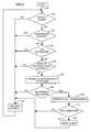
- FIG. 2illustrates the steps performed by controller 109 in implementing the invention.
- decision block 202determines if a battery alarm is being received from the battery detector. If the answer is no in decision block 202 , control is passed to block 213 that performs normal processing on the stimuli. This normal processing consists of doing nothing if there is no stimuli, responding to an incoming call, placing an outgoing call, etc. If a battery alarm is being received, control is passed to decision block 203 that determines whether or not the maintenance center has been notified as will be discussed in block 209 . If the answer is yes, control is transferred once again to block 213 which processes the stimuli in a normal manner before returning control back to decision block 202 .
- decision block 204determines if the telephone is originating a call. If the answer is no control is transferred to block 213 . If the answer in decision block 204 is yes, control is transferred to decision block 206 which determines if the call origination is being placed to the emergency number by examining the initial dialed digits for the emergency digit sequence. If the user of the telephone is placing a call to the emergency number, control is transferred to block 213 so that this emergency call can be processed in a normal manner. If decision block 206 determines that a call is not being placed to the emergency number, control is transferred to block 207 which transmits the alarm message to telephone so that the user can respond or not.
- decision block 208determines if the user is requesting to be connected to the maintenance center in response to the transmitted alarm message. If the answer is no, control is transferred to block 213 . If the answer is yes, control is transferred to block 209 that originates a call to the maintenance center before transferring control to decision block 211 . The latter decision block determines if the call has been completed to the maintenance center. If the answer is no, the user is allowed to proceed with the outgoing call that they were originating by control being transferred to block 213 . In this situation, the next time that the user originates a call they will once again receive the pre-recorded announcement. If the call to the maintenance center is completed successfully, control is passed to block 212 which transmits a signal to battery detector 111 to reset the alarm for a predetermined period before transferring control to block 213 .
- FIG. 3illustrates an embodiment of the invention for performing operations in a fixed wireless system.
- Wireless circuit 304performs all of the wireless operations under the control of controller 309 .
- controller 309performs the steps illustrated in FIG. 2 .
- Handset interface 306performs the analog to digital conversions and also provides ringing and other types of signaling for handset 311 .
- Multiplexer 307is utilized to communicate audio information with either wireless circuit 304 or controller 309 .
- User display 312is utilized to communicate information to the user of handset 311 .
- Elements 301 - 303 and 308perform the same functions as elements 113 - 116 and 111 of FIG. 1 .
- controller 109could immediately upon receiving the alarm signal from battery detector 111 place a call to telephone 112 and transmit the alarm message to telephone 112 at that time.
- controller 109could immediately upon receiving the alarm signal from battery detector 111 place a call to telephone 112 and transmit the alarm message to telephone 112 at that time.
Landscapes
- Engineering & Computer Science (AREA)
- Computer Networks & Wireless Communication (AREA)
- Signal Processing (AREA)
- Business, Economics & Management (AREA)
- Emergency Management (AREA)
- Human Computer Interaction (AREA)
- Telephonic Communication Services (AREA)
- Alarm Systems (AREA)
Abstract
Description
This invention relates to cable broadband or wireless apparatus and, in particular, to the notification of a battery alarm in an uninterruptible power supply (UPS).
When broadband access apparatus, such as cable or fixed wireless, is used to provide primary line telephone service, it is necessary to provide uninterruptible power supply service for endpoints so as to provide emergency service i.e., 911 calls. This is necessary since the network interface unit (NIU) or wireless adapter does not obtain its power from a telephone central office but rather must rely on power provided within the residence or business. Uninterruptible power supplies (UPS) that provide power from a battery when the main AC supply fails are well known in the art. However, a problem that exists with UPS's is the problem of detecting and replacing batteries that fail in these UPS's. Within the prior art, it is well known to use visual indicators and audio alarms to notify users that a battery has failed in a UPS. In addition, expensive and costly records are maintained to manage replacement schedules. Such prior art techniques work well within an environment where trained service personnel are on-site or make frequent visits to the sites.
However, in the case of NIU's, these units reside in residences and in small businesses where service personnel do not make routine visits. Visual indicators and audible alarms can also be used in the wireless units and NIU's but the effectiveness of these methods is greatly diminished. The user will often choose to ignore a visual indicator. With respect to audio alarms, such alarms must be able to be disabled since it may be a number of hours or even days before a service person can reach the residence to replace the battery. The result is that the users disable the audio alarm and then, not bother to call the service personnel to replace the battery in the UPS. This has left the providers providing service via the NIU's and wireless units in a quandary because of the problems and liabilities associated with maintaining and replacing the batteries in the UPSs because of the requirements placed on these service providers to provide primary line telephone emergency service.
The foregoing problem is solved and a technical advance is achieved by an apparatus and method that transmits a pre-recorded announcement to the user of an network interface unit (NIU) each time the user places a telephone call if an alarm is set because a battery in an uninterruptible power supply (UPS) is in a low power state. The pre-recorded announcement states that the battery needs to be replaced. Advantageously, the user is given a simple procedure for contacting service personnel at a service center to have the battery replaced in the UPS. In addition, this announcement is overridden if the user starts to dial the emergency telephone number (911). This allows the user to gain immediate access to the emergency telephone number without having to listen to the message stating that the battery in the UPS needs to be replaced. Advantageously, an indicator is also set on NIU upon the battery being in the low power state. If a call is completed to the service center, the alarm is reset for a predetermined amount of time to give the service personnel time to service the battery.
These and other features and advantages of the invention will become apparent from the following description of the illustrated embodiment of the invention considered together with the drawing.
FIG. 1 is a block diagram of a cable unit for implementing the invention;
FIG. 2 illustrates, in flowchart form, steps performed by a unit in implementing the invention; and
FIG. 3 illustrates, in block diagram form, a wireless unit for implementing the invention.
FIG. 1 illustrates, in block diagram form, an apparatus for implementing the invention.Interface 101 interfaces with the cable that is transmitting and receiving signals from the head end of the cable system.Interface 101 is in communication withvideo control 102,cable modem 103, andaudio interface 104.Video control 102 andcable modem 103 are not discussed but they provide the video and data communication with the head end.Controller 109 provides overall control of the apparatus illustrated in FIG.1.Audio interface 104 receives and transmits audio information with the head end viainterface 101.Multiplexer 107 under control ofcontroller 109 can communicate audio information with AD/DA converter 108 oraudio interface 104.Telephone interface 106 provides the standard telephone interface fortelephone 112.Telephone interface 106 provides the power on the tip and ring totelephone 112 and receives and transmits audio information frommultiplexer 107. Unit power is supplied to the apparatus at FIG. 1 fromAC supply 116 in normal operating conditions. However, if the AC power should fail,battery 114 supplies power. Note, that it is well known in the art thatbattery 114 in case of failure would only supply power to those units necessary fortelephone 112 to receive and make telephone calls.
In normal operation,controller 109 communicates control information concerning telephone calls and other aspects of the apparatus with the head end viaaudio interface 104. When an incoming call is received from the head end,controller 109 enablestelephone interface 109 to alerttelephone 112.Controller 109 then determines whentelephone 112 has answered the alerting, and interconnectstelephone 112 to the head end viatelephone interface 106,multiplexer 107, andaudio interface 104. In the normal situation for call origination,controller 109 detects whentelephone 112 goes off hook and establishes the necessary signaling with the head end to allowtelephone 112 to establish an outgoing call. Note, thattelephone 112 can dial the destination telephone number directly to the head end using multi-frequency tones, orcontroller 109 can interpret the multi-frequency tones and transmit the destination telephone number via a separate control channel to the head end.
Whenbattery 114 fails,battery detector 111 transmits, an alarm signal to controller109. As is discussed in greater detail with respect to FIG. 2,controller 109 is responsive to the alarm frombattery detector 111 to transmit a voice message to telephone112 thenext time telephone 112 attempts to perform a call origination. An exception to this operation is ifcontroller 109 detects thattelephone 112 is dialing the emergency telephone number e.g., 911. Iftelephone 112 is dialing the emergency telephone number,controller 109 will not transmit the battery alert message totelephone 112.
The battery alarm message could advantageously state, “Your telephone emergency batteries need replacement.
Press the digits ‘xyz’ to schedule an appointment with your service provider”. The digits “xyz” would be chosen to be digits that normally would not be dialed such as “000”. If the user indicates that indeed they wish to contact the service provider by dialing the requested digits,controller 109 establishes a call to the maintenance center and assures that the call was received and answered by the maintenance center. Once the call had ended with the maintenance center,controller 109 instructsbattery detector 111 to reset the battery alarm for a predetermined amount of time. If the predetermined amount of time elapses, andbattery 114 is still in a failed state,battery detector 111 once again sends an alarm signal to controller109. In addition, to sending a voice message totelephone 112,controller 109 also setsindicator 117 upon the occurrence of the alarm signal.Indicator 117 can be a visual or audio indicator. One skilled in the art can readily see that this resetting of the alarm for a predetermined amount of time could be performed bycontroller 109 through software methods.
FIG. 2 illustrates the steps performed bycontroller 109 in implementing the invention. After being started inblock 201,decision block 202 determines if a battery alarm is being received from the battery detector. If the answer is no indecision block 202, control is passed to block213 that performs normal processing on the stimuli. This normal processing consists of doing nothing if there is no stimuli, responding to an incoming call, placing an outgoing call, etc. If a battery alarm is being received, control is passed to decision block203 that determines whether or not the maintenance center has been notified as will be discussed inblock 209. If the answer is yes, control is transferred once again to block213 which processes the stimuli in a normal manner before returning control back todecision block 202. If the response indecision block 203 is no, control is transferred todecision block 204. The latter decision block determines if the telephone is originating a call. If the answer is no control is transferred to block213. If the answer indecision block 204 is yes, control is transferred to decision block206 which determines if the call origination is being placed to the emergency number by examining the initial dialed digits for the emergency digit sequence. If the user of the telephone is placing a call to the emergency number, control is transferred to block213 so that this emergency call can be processed in a normal manner. Ifdecision block 206 determines that a call is not being placed to the emergency number, control is transferred to block207 which transmits the alarm message to telephone so that the user can respond or not.
After execution ofblock 207,decision block 208 determines if the user is requesting to be connected to the maintenance center in response to the transmitted alarm message. If the answer is no, control is transferred to block213. If the answer is yes, control is transferred to block209 that originates a call to the maintenance center before transferring control todecision block 211. The latter decision block determines if the call has been completed to the maintenance center. If the answer is no, the user is allowed to proceed with the outgoing call that they were originating by control being transferred to block213. In this situation, the next time that the user originates a call they will once again receive the pre-recorded announcement. If the call to the maintenance center is completed successfully, control is passed to block212 which transmits a signal tobattery detector 111 to reset the alarm for a predetermined period before transferring control to block213.
FIG. 3 illustrates an embodiment of the invention for performing operations in a fixed wireless system.Wireless circuit 304 performs all of the wireless operations under the control ofcontroller 309. In implementing the invention,controller 309 performs the steps illustrated in FIG.2.Handset interface 306 performs the analog to digital conversions and also provides ringing and other types of signaling forhandset 311.Multiplexer 307 is utilized to communicate audio information with eitherwireless circuit 304 orcontroller 309.User display 312 is utilized to communicate information to the user ofhandset 311. Elements301-303 and308 perform the same functions as elements113-116 and111 of FIG.1.
Of course, various changes and modifications to the illustrative embodiment described above will be apparent to those skilled in the art. For example,controller 109 could immediately upon receiving the alarm signal frombattery detector 111 place a call to telephone112 and transmit the alarm message to telephone112 at that time. Such changes and modifications can be made without departing from the spirit and scope of the invention and without diminishing its attendant advantages. It is therefore intended that such changes and modifications be covered by the following claims except insofar as limited by the prior art.
Claims (12)
1. A method providing of a battery alarm for a battery in an uninterruptible power supply of a local control unit providing service for a telephone, comprising the steps of:
generating an alarm when the battery is in a low power state by a battery detector in the local control unit;
determining that the battery is in the low power state by a presence of the alarm;
detecting a call origination by the telephone;
transmitting a voice message to the telephone in response to a call origination upon the call origination being for a non-emergency call where the voice message informs the user that the battery is in the low power state before allowing user to continue with the call origination;
providing a user of the telephone abbreviated dialing to originate another telephone call to a service center for the local control unit; and
resetting the alarm for a predetermined amount of time upon the other telephone call being completed to the service center.
2. The method ofclaim 1 wherein the step of determining comprises the step of setting an indicator on the local control unit upon the alarm being presence.
3. The method ofclaim 1 wherein the step of generating comprises the step of setting the alarm in response to elapse of the predetermined amount of time and the battery being in a low power state by the battery detector.
4. The method ofclaim 3 wherein the step of transmitting comprises the step of completing the telephone call without the transmitting the voice message upon telephone call being an emergency call.
5. The method ofclaim 4 wherein the local control unit is a network interface unit connected to a broadband cable.
6. The method ofclaim 4 wherein the local control unit is a fixed wireless controller.
7. An apparatus for performing the method ofclaim 1 .
8. An apparatus for performing the method ofclaim 2 .
9. An apparatus for performing the method ofclaim 3 .
10. An apparatus for performing the method ofclaim 4 .
11. An apparatus for performing the method ofclaim 5 .
12. An apparatus for performing the method ofclaim 6 .
Priority Applications (1)
| Application Number | Priority Date | Filing Date | Title |
|---|---|---|---|
| US09/641,482US6650750B1 (en) | 2000-08-18 | 2000-08-18 | Voice notification for a battery alarm in a network interface unit |
Applications Claiming Priority (1)
| Application Number | Priority Date | Filing Date | Title |
|---|---|---|---|
| US09/641,482US6650750B1 (en) | 2000-08-18 | 2000-08-18 | Voice notification for a battery alarm in a network interface unit |
Publications (1)
| Publication Number | Publication Date |
|---|---|
| US6650750B1true US6650750B1 (en) | 2003-11-18 |
Family
ID=29420802
Family Applications (1)
| Application Number | Title | Priority Date | Filing Date |
|---|---|---|---|
| US09/641,482Expired - Fee RelatedUS6650750B1 (en) | 2000-08-18 | 2000-08-18 | Voice notification for a battery alarm in a network interface unit |
Country Status (1)
| Country | Link |
|---|---|
| US (1) | US6650750B1 (en) |
Cited By (3)
| Publication number | Priority date | Publication date | Assignee | Title |
|---|---|---|---|---|
| US20040235534A1 (en)* | 2000-04-17 | 2004-11-25 | Owens Michael Kevin | Remote battery replacement notification system and method |
| US20060187071A1 (en)* | 2005-02-11 | 2006-08-24 | Sbc Knowledge Ventures, L.P. | System and method for notification of power system status |
| US20080247760A1 (en)* | 2007-04-09 | 2008-10-09 | At&T Knowledge Ventures, L.P. | System for wireless alarm reporting |
Citations (5)
| Publication number | Priority date | Publication date | Assignee | Title |
|---|---|---|---|---|
| US5566339A (en)* | 1992-10-23 | 1996-10-15 | Fox Network Systems, Inc. | System and method for monitoring computer environment and operation |
| US5646606A (en)* | 1991-05-30 | 1997-07-08 | Wilson; Alan L. | Transmission of transmitter parameters in a digital communication system |
| US5761312A (en)* | 1995-06-07 | 1998-06-02 | Zelikovitz, Deceased; Joseph | Enhanced individual intelligent communication platform for subscribers on a telephone system |
| US6144848A (en)* | 1995-06-07 | 2000-11-07 | Weiss Jensen Ellis & Howard | Handheld remote computer control and methods for secured interactive real-time telecommunications |
| US6452490B1 (en)* | 1999-08-24 | 2002-09-17 | Lucent Technologies Inc. | Home/commercial security monitoring system |
- 2000
- 2000-08-18USUS09/641,482patent/US6650750B1/ennot_activeExpired - Fee Related
Patent Citations (5)
| Publication number | Priority date | Publication date | Assignee | Title |
|---|---|---|---|---|
| US5646606A (en)* | 1991-05-30 | 1997-07-08 | Wilson; Alan L. | Transmission of transmitter parameters in a digital communication system |
| US5566339A (en)* | 1992-10-23 | 1996-10-15 | Fox Network Systems, Inc. | System and method for monitoring computer environment and operation |
| US5761312A (en)* | 1995-06-07 | 1998-06-02 | Zelikovitz, Deceased; Joseph | Enhanced individual intelligent communication platform for subscribers on a telephone system |
| US6144848A (en)* | 1995-06-07 | 2000-11-07 | Weiss Jensen Ellis & Howard | Handheld remote computer control and methods for secured interactive real-time telecommunications |
| US6452490B1 (en)* | 1999-08-24 | 2002-09-17 | Lucent Technologies Inc. | Home/commercial security monitoring system |
Cited By (6)
| Publication number | Priority date | Publication date | Assignee | Title |
|---|---|---|---|---|
| US20040235534A1 (en)* | 2000-04-17 | 2004-11-25 | Owens Michael Kevin | Remote battery replacement notification system and method |
| US7457647B2 (en) | 2000-04-17 | 2008-11-25 | At&T Intellectual Property I, L.P. | Remote battery replacement notification system and method |
| US20090041228A1 (en)* | 2000-04-17 | 2009-02-12 | Michael Kevin Owens | Remote battery replacement notification system and method |
| US8060081B2 (en) | 2000-04-17 | 2011-11-15 | At&T Intellectual Property I, L.P. | Remote battery replacement notification system and method |
| US20060187071A1 (en)* | 2005-02-11 | 2006-08-24 | Sbc Knowledge Ventures, L.P. | System and method for notification of power system status |
| US20080247760A1 (en)* | 2007-04-09 | 2008-10-09 | At&T Knowledge Ventures, L.P. | System for wireless alarm reporting |
Similar Documents
| Publication | Publication Date | Title |
|---|---|---|
| US5371781A (en) | System and method for identifying the incoming directory number when multiple directory numbers are assigned to one wireless device | |
| US8085905B2 (en) | Multimedia emergency services | |
| WO1995018501A1 (en) | Method and apparatus for message delivery using local visual/audible indication | |
| US20050245250A1 (en) | Device, system and method for detection of communication disconnection | |
| US6650750B1 (en) | Voice notification for a battery alarm in a network interface unit | |
| JP7091989B2 (en) | Emergency call device | |
| KR100298421B1 (en) | Automatic receiving terminal unit and control method thereof | |
| JP7275867B2 (en) | emergency call device | |
| JP2004096485A (en) | Telephone control system | |
| JP3337015B2 (en) | Wireless local loop system and its fault detection / reporting method | |
| JP2017085401A (en) | Auxiliary reception device, call reception system and auxiliary reception method | |
| KR20140052316A (en) | Apparatus and method for emergency call using mobile-phone application | |
| JP7234822B2 (en) | emergency call system | |
| GB2327172A (en) | Voice mail service with automatic message delivery | |
| JP2001008248A (en) | Key telephone system | |
| JP7234823B2 (en) | emergency call system | |
| JPS58213558A (en) | Multi-line switching system | |
| JPH0158557B2 (en) | ||
| JP2835411B2 (en) | Network controller | |
| JPS59134968A (en) | emergency call phone | |
| JP2003198758A (en) | Emergency report system using portable terminal | |
| JPH04329035A (en) | Radio calling receiver | |
| JP2003289401A (en) | Abnormality notice system, abnormality notifying apparatus and notice receiving apparatus | |
| KR20100118693A (en) | Status information management method and system of mobile communication terminal | |
| JP2001061015A (en) | Emergency call system |
Legal Events
| Date | Code | Title | Description |
|---|---|---|---|
| AS | Assignment | Owner name:LUCENT TECHNOLOGIES INC., NEW JERSEY Free format text:ASSIGNMENT OF ASSIGNORS INTEREST;ASSIGNOR:BORTOLINI, EDWARD J.;REEL/FRAME:011146/0319 Effective date:20000818 | |
| FEPP | Fee payment procedure | Free format text:PAYOR NUMBER ASSIGNED (ORIGINAL EVENT CODE: ASPN); ENTITY STATUS OF PATENT OWNER: LARGE ENTITY | |
| FPAY | Fee payment | Year of fee payment:4 | |
| FPAY | Fee payment | Year of fee payment:8 | |
| AS | Assignment | Owner name:CREDIT SUISSE AG, NEW YORK Free format text:SECURITY INTEREST;ASSIGNOR:ALCATEL-LUCENT USA INC.;REEL/FRAME:030510/0627 Effective date:20130130 | |
| AS | Assignment | Owner name:ALCATEL-LUCENT USA INC., NEW JERSEY Free format text:RELEASE BY SECURED PARTY;ASSIGNOR:CREDIT SUISSE AG;REEL/FRAME:033949/0531 Effective date:20140819 | |
| REMI | Maintenance fee reminder mailed | ||
| LAPS | Lapse for failure to pay maintenance fees | ||
| STCH | Information on status: patent discontinuation | Free format text:PATENT EXPIRED DUE TO NONPAYMENT OF MAINTENANCE FEES UNDER 37 CFR 1.362 | |
| FP | Lapsed due to failure to pay maintenance fee | Effective date:20151118 |