US6648894B2 - Bone graft forming guide and method of forming bone grafts - Google Patents
Bone graft forming guide and method of forming bone graftsDownload PDFInfo
- Publication number
- US6648894B2 US6648894B2US09/742,923US74292300AUS6648894B2US 6648894 B2US6648894 B2US 6648894B2US 74292300 AUS74292300 AUS 74292300AUS 6648894 B2US6648894 B2US 6648894B2
- Authority
- US
- United States
- Prior art keywords
- guide
- cutting
- bone graft
- forming
- pattern
- Prior art date
- Legal status (The legal status is an assumption and is not a legal conclusion. Google has not performed a legal analysis and makes no representation as to the accuracy of the status listed.)
- Expired - Fee Related, expires
Links
Images


Classifications
- A—HUMAN NECESSITIES
- A61—MEDICAL OR VETERINARY SCIENCE; HYGIENE
- A61B—DIAGNOSIS; SURGERY; IDENTIFICATION
- A61B17/00—Surgical instruments, devices or methods
- A61B17/56—Surgical instruments or methods for treatment of bones or joints; Devices specially adapted therefor
- A—HUMAN NECESSITIES
- A61—MEDICAL OR VETERINARY SCIENCE; HYGIENE
- A61F—FILTERS IMPLANTABLE INTO BLOOD VESSELS; PROSTHESES; DEVICES PROVIDING PATENCY TO, OR PREVENTING COLLAPSING OF, TUBULAR STRUCTURES OF THE BODY, e.g. STENTS; ORTHOPAEDIC, NURSING OR CONTRACEPTIVE DEVICES; FOMENTATION; TREATMENT OR PROTECTION OF EYES OR EARS; BANDAGES, DRESSINGS OR ABSORBENT PADS; FIRST-AID KITS
- A61F2/00—Filters implantable into blood vessels; Prostheses, i.e. artificial substitutes or replacements for parts of the body; Appliances for connecting them with the body; Devices providing patency to, or preventing collapsing of, tubular structures of the body, e.g. stents
- A61F2/02—Prostheses implantable into the body
- A61F2/30—Joints
- A61F2/46—Special tools for implanting artificial joints
- A61F2/4644—Preparation of bone graft, bone plugs or bone dowels, e.g. grinding or milling bone material
- A—HUMAN NECESSITIES
- A61—MEDICAL OR VETERINARY SCIENCE; HYGIENE
- A61F—FILTERS IMPLANTABLE INTO BLOOD VESSELS; PROSTHESES; DEVICES PROVIDING PATENCY TO, OR PREVENTING COLLAPSING OF, TUBULAR STRUCTURES OF THE BODY, e.g. STENTS; ORTHOPAEDIC, NURSING OR CONTRACEPTIVE DEVICES; FOMENTATION; TREATMENT OR PROTECTION OF EYES OR EARS; BANDAGES, DRESSINGS OR ABSORBENT PADS; FIRST-AID KITS
- A61F2/00—Filters implantable into blood vessels; Prostheses, i.e. artificial substitutes or replacements for parts of the body; Appliances for connecting them with the body; Devices providing patency to, or preventing collapsing of, tubular structures of the body, e.g. stents
- A61F2/02—Prostheses implantable into the body
- A61F2/30—Joints
- A61F2/3094—Designing or manufacturing processes
- A—HUMAN NECESSITIES
- A61—MEDICAL OR VETERINARY SCIENCE; HYGIENE
- A61F—FILTERS IMPLANTABLE INTO BLOOD VESSELS; PROSTHESES; DEVICES PROVIDING PATENCY TO, OR PREVENTING COLLAPSING OF, TUBULAR STRUCTURES OF THE BODY, e.g. STENTS; ORTHOPAEDIC, NURSING OR CONTRACEPTIVE DEVICES; FOMENTATION; TREATMENT OR PROTECTION OF EYES OR EARS; BANDAGES, DRESSINGS OR ABSORBENT PADS; FIRST-AID KITS
- A61F2/00—Filters implantable into blood vessels; Prostheses, i.e. artificial substitutes or replacements for parts of the body; Appliances for connecting them with the body; Devices providing patency to, or preventing collapsing of, tubular structures of the body, e.g. stents
- A61F2/02—Prostheses implantable into the body
- A61F2/30—Joints
- A61F2/44—Joints for the spine, e.g. vertebrae, spinal discs
- A61F2/442—Intervertebral or spinal discs, e.g. resilient
- A—HUMAN NECESSITIES
- A61—MEDICAL OR VETERINARY SCIENCE; HYGIENE
- A61F—FILTERS IMPLANTABLE INTO BLOOD VESSELS; PROSTHESES; DEVICES PROVIDING PATENCY TO, OR PREVENTING COLLAPSING OF, TUBULAR STRUCTURES OF THE BODY, e.g. STENTS; ORTHOPAEDIC, NURSING OR CONTRACEPTIVE DEVICES; FOMENTATION; TREATMENT OR PROTECTION OF EYES OR EARS; BANDAGES, DRESSINGS OR ABSORBENT PADS; FIRST-AID KITS
- A61F2/00—Filters implantable into blood vessels; Prostheses, i.e. artificial substitutes or replacements for parts of the body; Appliances for connecting them with the body; Devices providing patency to, or preventing collapsing of, tubular structures of the body, e.g. stents
- A61F2/02—Prostheses implantable into the body
- A61F2/30—Joints
- A61F2/44—Joints for the spine, e.g. vertebrae, spinal discs
- A61F2/4455—Joints for the spine, e.g. vertebrae, spinal discs for the fusion of spinal bodies, e.g. intervertebral fusion of adjacent spinal bodies, e.g. fusion cages
- A61F2/4465—Joints for the spine, e.g. vertebrae, spinal discs for the fusion of spinal bodies, e.g. intervertebral fusion of adjacent spinal bodies, e.g. fusion cages having a circular or kidney shaped cross-section substantially perpendicular to the axis of the spine
- A—HUMAN NECESSITIES
- A61—MEDICAL OR VETERINARY SCIENCE; HYGIENE
- A61F—FILTERS IMPLANTABLE INTO BLOOD VESSELS; PROSTHESES; DEVICES PROVIDING PATENCY TO, OR PREVENTING COLLAPSING OF, TUBULAR STRUCTURES OF THE BODY, e.g. STENTS; ORTHOPAEDIC, NURSING OR CONTRACEPTIVE DEVICES; FOMENTATION; TREATMENT OR PROTECTION OF EYES OR EARS; BANDAGES, DRESSINGS OR ABSORBENT PADS; FIRST-AID KITS
- A61F2/00—Filters implantable into blood vessels; Prostheses, i.e. artificial substitutes or replacements for parts of the body; Appliances for connecting them with the body; Devices providing patency to, or preventing collapsing of, tubular structures of the body, e.g. stents
- A61F2/02—Prostheses implantable into the body
- A61F2/30—Joints
- A61F2/46—Special tools for implanting artificial joints
- A61F2/4603—Special tools for implanting artificial joints for insertion or extraction of endoprosthetic joints or of accessories thereof
- A—HUMAN NECESSITIES
- A61—MEDICAL OR VETERINARY SCIENCE; HYGIENE
- A61F—FILTERS IMPLANTABLE INTO BLOOD VESSELS; PROSTHESES; DEVICES PROVIDING PATENCY TO, OR PREVENTING COLLAPSING OF, TUBULAR STRUCTURES OF THE BODY, e.g. STENTS; ORTHOPAEDIC, NURSING OR CONTRACEPTIVE DEVICES; FOMENTATION; TREATMENT OR PROTECTION OF EYES OR EARS; BANDAGES, DRESSINGS OR ABSORBENT PADS; FIRST-AID KITS
- A61F2/00—Filters implantable into blood vessels; Prostheses, i.e. artificial substitutes or replacements for parts of the body; Appliances for connecting them with the body; Devices providing patency to, or preventing collapsing of, tubular structures of the body, e.g. stents
- A61F2/02—Prostheses implantable into the body
- A61F2/28—Bones
- A61F2002/2835—Bone graft implants for filling a bony defect or an endoprosthesis cavity, e.g. by synthetic material or biological material
- A61F2002/2839—Bone plugs or bone graft dowels
- A—HUMAN NECESSITIES
- A61—MEDICAL OR VETERINARY SCIENCE; HYGIENE
- A61F—FILTERS IMPLANTABLE INTO BLOOD VESSELS; PROSTHESES; DEVICES PROVIDING PATENCY TO, OR PREVENTING COLLAPSING OF, TUBULAR STRUCTURES OF THE BODY, e.g. STENTS; ORTHOPAEDIC, NURSING OR CONTRACEPTIVE DEVICES; FOMENTATION; TREATMENT OR PROTECTION OF EYES OR EARS; BANDAGES, DRESSINGS OR ABSORBENT PADS; FIRST-AID KITS
- A61F2/00—Filters implantable into blood vessels; Prostheses, i.e. artificial substitutes or replacements for parts of the body; Appliances for connecting them with the body; Devices providing patency to, or preventing collapsing of, tubular structures of the body, e.g. stents
- A61F2/02—Prostheses implantable into the body
- A61F2/30—Joints
- A61F2002/30001—Additional features of subject-matter classified in A61F2/28, A61F2/30 and subgroups thereof
- A61F2002/30108—Shapes
- A61F2002/3011—Cross-sections or two-dimensional shapes
- A61F2002/30112—Rounded shapes, e.g. with rounded corners
- A61F2002/30125—Rounded shapes, e.g. with rounded corners elliptical or oval
- A61F2002/30126—Rounded shapes, e.g. with rounded corners elliptical or oval oval-O-shaped
- A—HUMAN NECESSITIES
- A61—MEDICAL OR VETERINARY SCIENCE; HYGIENE
- A61F—FILTERS IMPLANTABLE INTO BLOOD VESSELS; PROSTHESES; DEVICES PROVIDING PATENCY TO, OR PREVENTING COLLAPSING OF, TUBULAR STRUCTURES OF THE BODY, e.g. STENTS; ORTHOPAEDIC, NURSING OR CONTRACEPTIVE DEVICES; FOMENTATION; TREATMENT OR PROTECTION OF EYES OR EARS; BANDAGES, DRESSINGS OR ABSORBENT PADS; FIRST-AID KITS
- A61F2/00—Filters implantable into blood vessels; Prostheses, i.e. artificial substitutes or replacements for parts of the body; Appliances for connecting them with the body; Devices providing patency to, or preventing collapsing of, tubular structures of the body, e.g. stents
- A61F2/02—Prostheses implantable into the body
- A61F2/30—Joints
- A61F2/30767—Special external or bone-contacting surface, e.g. coating for improving bone ingrowth
- A61F2/30771—Special external or bone-contacting surface, e.g. coating for improving bone ingrowth applied in original prostheses, e.g. holes or grooves
- A61F2002/30772—Apertures or holes, e.g. of circular cross section
- A61F2002/30777—Oblong apertures
- A—HUMAN NECESSITIES
- A61—MEDICAL OR VETERINARY SCIENCE; HYGIENE
- A61F—FILTERS IMPLANTABLE INTO BLOOD VESSELS; PROSTHESES; DEVICES PROVIDING PATENCY TO, OR PREVENTING COLLAPSING OF, TUBULAR STRUCTURES OF THE BODY, e.g. STENTS; ORTHOPAEDIC, NURSING OR CONTRACEPTIVE DEVICES; FOMENTATION; TREATMENT OR PROTECTION OF EYES OR EARS; BANDAGES, DRESSINGS OR ABSORBENT PADS; FIRST-AID KITS
- A61F2/00—Filters implantable into blood vessels; Prostheses, i.e. artificial substitutes or replacements for parts of the body; Appliances for connecting them with the body; Devices providing patency to, or preventing collapsing of, tubular structures of the body, e.g. stents
- A61F2/02—Prostheses implantable into the body
- A61F2/30—Joints
- A61F2/30767—Special external or bone-contacting surface, e.g. coating for improving bone ingrowth
- A61F2/30771—Special external or bone-contacting surface, e.g. coating for improving bone ingrowth applied in original prostheses, e.g. holes or grooves
- A61F2002/3082—Grooves
- A61F2002/30827—Plurality of grooves
- A61F2002/30828—Plurality of grooves parallel
- A—HUMAN NECESSITIES
- A61—MEDICAL OR VETERINARY SCIENCE; HYGIENE
- A61F—FILTERS IMPLANTABLE INTO BLOOD VESSELS; PROSTHESES; DEVICES PROVIDING PATENCY TO, OR PREVENTING COLLAPSING OF, TUBULAR STRUCTURES OF THE BODY, e.g. STENTS; ORTHOPAEDIC, NURSING OR CONTRACEPTIVE DEVICES; FOMENTATION; TREATMENT OR PROTECTION OF EYES OR EARS; BANDAGES, DRESSINGS OR ABSORBENT PADS; FIRST-AID KITS
- A61F2/00—Filters implantable into blood vessels; Prostheses, i.e. artificial substitutes or replacements for parts of the body; Appliances for connecting them with the body; Devices providing patency to, or preventing collapsing of, tubular structures of the body, e.g. stents
- A61F2/02—Prostheses implantable into the body
- A61F2/30—Joints
- A61F2/30767—Special external or bone-contacting surface, e.g. coating for improving bone ingrowth
- A61F2/30771—Special external or bone-contacting surface, e.g. coating for improving bone ingrowth applied in original prostheses, e.g. holes or grooves
- A61F2002/30904—Special external or bone-contacting surface, e.g. coating for improving bone ingrowth applied in original prostheses, e.g. holes or grooves serrated profile, i.e. saw-toothed
- A—HUMAN NECESSITIES
- A61—MEDICAL OR VETERINARY SCIENCE; HYGIENE
- A61F—FILTERS IMPLANTABLE INTO BLOOD VESSELS; PROSTHESES; DEVICES PROVIDING PATENCY TO, OR PREVENTING COLLAPSING OF, TUBULAR STRUCTURES OF THE BODY, e.g. STENTS; ORTHOPAEDIC, NURSING OR CONTRACEPTIVE DEVICES; FOMENTATION; TREATMENT OR PROTECTION OF EYES OR EARS; BANDAGES, DRESSINGS OR ABSORBENT PADS; FIRST-AID KITS
- A61F2/00—Filters implantable into blood vessels; Prostheses, i.e. artificial substitutes or replacements for parts of the body; Appliances for connecting them with the body; Devices providing patency to, or preventing collapsing of, tubular structures of the body, e.g. stents
- A61F2/02—Prostheses implantable into the body
- A61F2/30—Joints
- A61F2/46—Special tools for implanting artificial joints
- A61F2/4644—Preparation of bone graft, bone plugs or bone dowels, e.g. grinding or milling bone material
- A61F2002/4649—Bone graft or bone dowel harvest sites
- A—HUMAN NECESSITIES
- A61—MEDICAL OR VETERINARY SCIENCE; HYGIENE
- A61F—FILTERS IMPLANTABLE INTO BLOOD VESSELS; PROSTHESES; DEVICES PROVIDING PATENCY TO, OR PREVENTING COLLAPSING OF, TUBULAR STRUCTURES OF THE BODY, e.g. STENTS; ORTHOPAEDIC, NURSING OR CONTRACEPTIVE DEVICES; FOMENTATION; TREATMENT OR PROTECTION OF EYES OR EARS; BANDAGES, DRESSINGS OR ABSORBENT PADS; FIRST-AID KITS
- A61F2230/00—Geometry of prostheses classified in groups A61F2/00 - A61F2/26 or A61F2/82 or A61F9/00 or A61F11/00 or subgroups thereof
- A61F2230/0002—Two-dimensional shapes, e.g. cross-sections
- A61F2230/0004—Rounded shapes, e.g. with rounded corners
- A61F2230/0008—Rounded shapes, e.g. with rounded corners elliptical or oval
- Y—GENERAL TAGGING OF NEW TECHNOLOGICAL DEVELOPMENTS; GENERAL TAGGING OF CROSS-SECTIONAL TECHNOLOGIES SPANNING OVER SEVERAL SECTIONS OF THE IPC; TECHNICAL SUBJECTS COVERED BY FORMER USPC CROSS-REFERENCE ART COLLECTIONS [XRACs] AND DIGESTS
- Y10—TECHNICAL SUBJECTS COVERED BY FORMER USPC
- Y10S—TECHNICAL SUBJECTS COVERED BY FORMER USPC CROSS-REFERENCE ART COLLECTIONS [XRACs] AND DIGESTS
- Y10S623/00—Prosthesis, i.e. artificial body members, parts thereof, or aids and accessories therefor
- Y10S623/92—Method or apparatus for preparing or treating prosthetic
- Y10S623/923—Bone
Definitions
- the present inventionrelates to bone grafts for use in the repair, replacement, and/or augmentation of various portions of animal or human skeletal systems. More particularly, the present invention relates to a prepared bone graft, guides for forming bone grafts and methods of forming bone grafts.
- implanted boneincludes providing support, promoting healing, filling bony cavities, separating or spacing bony elements such as vertebral bodies, promoting fusion, and stabilizing the site of fractures.
- a donor bone from a cadaveris selected and prepared for insertion into a patient.
- a spinal implantmay be prepared by selecting a femur or tibia bone and cutting the bone to a desired shape.
- a portion of a bonecan be cut from the patient receiving the implant, usually from a large bone such as a hip bone.
- the bone graftcan be a synthetic material which has been formed to a desired size and shape.
- bone graftsare prepared outside the operating room in a production facility, and inserts are prepared having a variety of shapes and sizes so that the physician performing a bone implant operation can select a properly sized and shaped implant for each patient and procedure.
- Production of bone graftcan be expensive because the production facility must be capable of producing sterile implants, and the bone graft must be stored prior to use in an operation.
- a roughened or irregular surface on at least one surface of the finished bone graftmay be desirable to provide a roughened or irregular surface on at least one surface of the finished bone graft to promote fusion of the graft to adjacent bone in the body.
- a surgeonmust have on hand a variety of bone graft sizes and shapes to precisely fit the bone graft into the disc space of the patient after preparation of the bone graft, which may include surgical removal of a ruptured or degenerated disc or a portion thereof.
- Such a methodshould be relatively simple, inexpensive and provide the flexibility of allowing the bone graft to be prepared intraoperatively in an operating room.
- the present inventiongenerally provides a relatively simple bone graft forming guide and a method of forming a bone graft.
- the methodincludes the steps of selecting the shape of at least a portion of a bone graft and forming a plurality of holes in a graft material.
- the plurality of holesforms a pattern generally corresponding to the intended shape of the bone graft.
- the inventionmay further include cutting at least partially through the graft material along the pattern formed by the plurality of holes.
- the cutting stepincludes cutting through at least a portion of the plurality of holes resulting in a portion of the bone graft having a roughened surface.
- Another aspect of the inventionincludes providing a drill guide containing a plurality of hole guides arranged in a pattern generally corresponding to the intended shape of the bone graft.
- the methodincludes positioning the drill guide with respect to the graft material and drilling into the graft material using a least a portion of the hole guides.
- the methodmay further include providing a cutting guide having a pattern corresponding the intended shape of the bone graft, positioning the cutting device with respect to the graft material, and cutting the graft material using the cutting guide.
- the drilling stepincludes drilling through the graft material and the cutting step includes cutting through the graft material.
- the methodis performed intraoperatively in an operating room.
- This aspect of the inventionprovides the surgeon performing a bone graft insertion procedure with the flexibility to select a properly sized and shaped bone graft in the operating room.
- a surgeonwould have to purchase various differently sized and shaped bone grafts that are fabricated in a facility outside the operating room.
- a spinal bone graftmay be formed in a generally elliptical shape with respect to the cutting direction.
- the hole guide and the cutting guidehave a pattern that is generally elliptical in shape.
- a spinal bone graftcan be produced that is generally cut in a wedge shape.
- Another aspect of the inventionpertains to a method of forming a bone graft from a graft material including the steps of selecting the shape of at least a portion of the bone graft, providing a graft material holder and selecting from a plurality of cutting guides, each of the cutting guides having a different cutting pattern.
- the methodfurther includes associating the cutting guide with the graft material holder and cutting at least a portion of the bone graft material using the cutting guide.
- the cutting guidehas a main body including a holder for holding a graft material and a cutting guide-receiving structure.
- This aspect of the inventionalso includes a cutting guide containing a pattern corresponding to the desired shape of the bone graft, and the cutting guide adapted to be detachably mounted to the main body.
- the forming guideincludes a main body having a holder for holding a graft material and a hole guide containing a plurality of hole guides arranged in a pattern generally corresponding to the desired shape of the bone graft.
- the forming guidefurther includes a cutting guide containing a pattern corresponding to the desired shape of the bone graft.
- the hole guideis an insert and the main body includes a guide receiving opening to receive the insert.
- the cutting guideis an insert and the main body includes an opening to receive the insert.
- the forming guideincludes a securing mechanism for removably securing one or both of the hole guide insert or the cutting guide insert in the opening.
- the securing mechanismincludes a cam member associated with the main body.
- the cam membercooperates with one or both of the hole guide insert or the cutting guide insert to secure one or both of the inserts to the main body.
- the hole guide insert and the cutting guide insertinclude a ridge adapted to cooperate with the cam member.
- the main body of the bone graft forming guideincludes a block adapted to receive a graft material.
- the blockincludes two members connected by a hinge.
- the main bodyfurther includes a closure means such as a clamping mechanism for clamping the two members towards each other to secure the bone within the cutting guide.
- the clamping mechanismincludes a threaded rod and nut assembly.
- the forming guideincludes a handle and a shaft having a proximal end and a distal end.
- the proximal end of the shaftis attached to the handle, and a pair of jaws extends from the distal end of the shaft.
- the jawsare movable between a gripping position to grip graft material during cutting of the bone graft and a releasing position to release the implant.
- the handleincludes pair of arms connected to the pair of jaws to provide a pair of gripping members that are pivotally joined.
- the pair of armsincludes a locking mechanism to lock the cutting guide in a plurality of positions.
- the cutting guidesare attached to at least one of the jaws.
- the hole guide and the cutting guideare removable inserts.
- the hole guide and the cutting guidemay be integrally formed in at least one of the jaws.
- a bone graft forming guideincluding a handle and a shaft having a proximal end and a distal end.
- the proximal end of the shaftis attached to the handle, and a pair of jaws extends from the distal end of the shaft.
- a cutting guideis associated with the jaws, and the jaws are movable between a gripping position to grip graft material during cutting of the bone graft and a releasing position to release the implant.
- the handleincludes a pair of arms connected to said pair of jaws to provide a pair of gripping members, the gripping members being pivotally joined.
- the present inventionprovides a relatively simple and inexpensive way to make bone grafts.
- a surgeoncan select a from a variety of hole guides and cutting guides to provide various sized and shaped bone grafts for a procedure.
- the method and forming guide of the inventioncan be used intraoperatively in an operating room setting.
- a roughened surfaceis provided on at least one surface of the bone graft.
- the hole guidescontain round holes, and the cutting guide is positioned such that the cutting device cuts through the approximate center of the holes to provide a roughened or ridged surface on at least one surface of the bone graft.
- the roughened surfacepromotes ease of insertion of the graft and fusion of the bone graft to an adjacent bone after insertion in the body.
- FIG. 1is an exploded perspective view of a bone graft forming guide in an open position and a bone graft material according to one aspect of the invention.
- FIG. 2is a perspective view of the forming guide of FIG. 1 in a closed position showing the bone graft material and a cutting insert in association with the forming guide.
- FIG. 3is a top plan view of a forming guide according to one aspect of the invention.
- FIG. 4is a front view of the forming guide of FIG. 2 .
- FIG. 5is a cross-section view taken along line 5 — 5 of FIG. 2 .
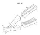
- FIG. 6is a perspective view of a bone graft in accordance with the invention.
- FIGS. 7A-7Dshow top views of examples of cutting inserts in accordance with the present invention.
- FIG. 8is a perspective view of a bone graft forming guide according to another embodiment of the invention.
- FIGS. 9A-9Cshows a partial perspective view of bone graft forming guides according to other embodiments of the invention.
- a bone graft forming guide 10 for forming a bone graft having a desired shapeincludes a main body 12 and a cutting guide 14 .
- the main bodyis in the form of a block of material adapted to receive and, preferably, position a graft material.
- the block of materialcomprises two members 22 and 24 connected by a hinge.
- the hingepreferably includes a pin 28 , which cooperates with hinge members 30 and 32 associated with main body members 20 and 22 to join the two members together and provide an axis of rotation for opening and closing the forming guide in use.
- the inventionis not limited by a requirement for separate body members or a requirement for a particular means of joining the members together or a specific hinge member.
- the two members 20 and 22may be joined together by a living hinge (not shown), wherein during the manufacturing process of the forming guide, a thinned section is provided that functions as a hinge and allows the two members to open and close.
- Other types of hingesare also within the scope of the invention, such as, for example, a piano hinge. Or, there may be no hinge at all, the two members being joined by any number of mechanical means.
- the cutting guide 14has a cutting pattern corresponding to the desired shape of the bone graft.
- the main body 12 of the forming guide 10includes a holder 16 for holding bone graft material 18 during formation of the bone graft.
- the holder 16may include a plurality of splines 34 on the inner surface of the main body for holding the bone graft material 18 during the forming operation.
- the splines 34are adapted to at least partially deform when they contact the graft material 18 and hold it in place during cutting of the bone graft material into a desired shape.
- the cutting guide 14is adapted to be detachably mounted to the main body 12 of the forming guide.
- One example of various ways in which the cutting guide 14 can be detachably mounted to the main body 12is to provide a cutting guide-receiving structure 20 associated with the main body 12 , as shown in FIGS. 1-3.
- the cutting guide-receiving structure 20may be an opening or nesting structure and the cutting guide 14 may be in the form of an insert sized to fit within the opening or nesting structure.
- the bone graft forming guideincludes a hole guide 36 containing a plurality of hole guides 38 arranged in a pattern generally corresponding to the desired shape of the bone graft.
- the hole guide 36 and the cutting guide 14may be selected as a pair having a similarly shaped pattern for forming a bone graft.
- hole guide insert 36 a shown in FIG. 7Awould desirably be used with the cutting guide insert 36 b shown in FIG. 7B as described further below to provide a bone graft having a wedge shape.
- the hole guide insert 36 d shown in FIG. 7Dwould be used with the cutting guide insert 14 c shown in FIG.
- the present inventiondesirably provides the advantage of enabling the surgeon to custom select the size and shape of a bone graft in the operating room to fit the graft to a particular patient and/or procedure.
- a bone graft forming guideincludes at least a main body having a holder for holding a bone graft material and a cutting guide containing a pattern corresponding to the desired shape of the bone graft.
- the cutting guideis detachably mounted to the main body of the forming guide.
- the forming guidemay optionally include a complementary hole guide for use with the cutting guide, the hole guide insert also adapted to be detachably mounted to the main body of the forming guide.
- a hole guideis desirable to provide a bone graft 38 having a roughened or irregular surface 40 on at least a portion of the bone graft 38 .
- a ruptured discmay be replaced with a bone graft, and the portions of the bone graft contacting the adjacent vertebrae may desirably be roughened to promote fusion of the insert to the adjacent vertebrae.
- the present inventionprovides a simple and inexpensive method of forming a bone graft having a roughened surface.
- the bone graft forming guideincludes a securing mechanism 42 for removably securing one or both of the hole guide insert or the cutting guide insert in the cutting guide-receiving structure 20 , which may be in the form of an opening or nesting structure adapted to receive the inserts.
- the securing mechanism 42includes a cam member associated with the main body 12 of the forming guide. The cam member 42 cooperates with one or both of the hole guide insert or the cutting guide insert to secure the inserts to the main body 12 .
- the insertmay optionally include a ridge 44 adapted to cooperate with the cam member to detachably secure the insert to the main body.
- the forming guidepreferably further includes a closure means such as a clamping mechanism 46 for moving the two members 22 and 24 towards each other to secure a bone graft material within the forming guide.
- the clamping mechanism 46may include a threaded rod 47 and nut 49 assembly.
- a bottom portion of the threaded rod 47may be secured to one of the members 22 in a manner to allow the threaded rod to pivot about the member 22 to move the threaded rod into and out of engagement with the other member 24 .
- the nut assembly 49may be rotated until the bone graft material 18 is securely held in the holder 16 of the main body 12 (as shown in FIG. 2 and FIG. 5 ).
- closure meanscan include a latch and hook assembly that is adapted to bias the two members 22 and 24 of the main body 12 together and hold bone graft material 18 in the forming guide.
- the closure meanscould include strap members that could be tightened to bias the two members 22 and 24 together.
- the closure meanscould be provided by screwing or bolting the main body members together, or any other suitable closure means could be used to bias the main body members together to hold the bone graft material in place during forming of the bone graft.
- the bone graft forming guideis preferably used intraoperatively in an operating room where a bone graft insertion procedure is performed.
- a surgeonwould have on hand a bone graft material, for example, a donor tibia bone as shown in the Figures, or the surgeon would cut a portion of bone from the patient or obtain a synthetically formed bone graft material. The surgeon would determine the size and shape of the bone graft that was needed for the particular procedure and the patient and then cut the bone graft as follows.
- the surgeonwould place the bone graft material 18 in the holder 16 of the forming guide 10 and select from a plurality of cutting guides provided to the surgeon in advance.
- the surgeonwould select the cutting guide insert that would provide the properly sized and shaped bone graft for the patient and the particular procedure.
- the surgeon or assistantwould then associate the cutting guide with the graft material holder, preferably by inserting a cutting guide insert in the opening sized to receive the cutting guide insert.
- the cutting guide insertwould then be secured to the main body of the forming guide by the cam member or other appropriate securing mechanism.
- the clamping mechanismwould then be engaged to bring the two members 22 and 24 of the main body 12 together and hold the bone graft material 18 in place during cutting of the bone graft.
- the bone graft materialwould then be at least partially cut along the pattern contained in the cutting guide to provide a bone graft having a desired shape. Cutting can be performed using any appropriate cutting device known in the art, such as a sagittal saw.
- the step of cutting the bone graftis preferably preceded, but may be followed, by forming a plurality of holes in a graft material, the plurality of holes forming a pattern generally corresponding to the shape of the bone graft.
- thiscan easily be achieved by first inserting a hole guide insert in the insert-receiving opening in the main body, securing the insert with the securing mechanism, and then forming a plurality of holes in the bone graft material by using at least a portion of a plurality of the holes in the drill guide.
- the term “drill” and “drilling”is not intended to be used in a limited manner to mean only traditional drill devices known in the art. Forming the plurality of holes may be accomplished by using a traditional drilling device and drill bits, or by other suitable machining methods such as by laser or ultrasonics.
- the hole guide insertmay be removed from the opening in the main body, and a cutting guide insert may be placed in the opening.
- the cutting guideis then secured to the main body, and the cutting operation is performed as described above.
- the resulting bone graftmay appear as shown in FIG. 6, having a roughened surface 40 .
- the present inventionprovides the flexibility of providing a wide variety of bone graft shapes, including, but not limited to, grafts that are straight, wedge-shaped, and elliptically shaped.
- the bone graft forming guide 60has a handle 64 having a proximal end 74 and a distal end 76 .
- a pair of jaws 78 and 80extends from the distal end 76 of the handle 72 .
- the jawsare movable between a gripping position to grip graft material during cutting of the bone graft and a releasing position to release the graft material (not shown).
- the handle 74includes a pair of arms connected to the pair of jaws 78 and 80 to provide the pair of gripping members, and the gripping members are pivotally joined by pivot point 82 .
- the pair of armsincludes a locking mechanism 84 to lock the forming guide 60 in a plurality of positions. These positions could include, for example, a closed position when the jaws are locked around the bone graft material during the cutting operation.
- the hole guide and/or cutting guideare attached to at least one of the jaws that make up the pair of jaws.
- the hole guidemay be integrally formed as part of the jaw.
- the hole guide and/or the cutting guidemay be detachably mounted to at least one of the jaws as shown in FIG. 9 a.
- attachment of the guidesmay be accomplished by screwing the guide to jaws, or by other appropriate means.
- the guidemay also be associated with the jaws by providing an insert receiving structure in the jaw and a hole guide insert and/or a cutting guide insert which fits into the insert similar to the insert receiving structure shown in FIGS. 1-7.
- a securing mechanismmay be included to secure the insert in to the jaw.
- Such securing mechanismscan include a cam mechanism, a ball and spring detent structure, snap, clips, or any other mechanism for securing the inserts in the insert receiving structure during cutting and forming of the bone graft.
- the insertsmay be provided in a variety of shapes and sizes.
- FIG. 9 bshows a cutting guide insert for making a wedge-shape.
- FIG. 9 cshows a combination hole-guide and cutting guide insert having a pattern of hole guides and cutting guides generally in the shape of an ellipse to form a elliptically-shaped bone graft.
- the embodiments shown in FIGS. 8 and 9can be used intraoperatively in an operating room setting.
- the surgeoncan be provided with several forming guides having a variety of sized and shaped hole and cutting guides.
- the surgeonwould determine the proper size and shape of the bone graft needed for the procedure.
- a bone graft materialsuch as a donor bone, would be gripped between the jaws of the forming guide, and the surgeon or assistant would apply pressure to the handles so that the jaws close on the bone graft material.
- the securing mechanismwould lock the jaws in place, and the bone graft material could be cut to the desired shape using an appropriate cutting device such as a sagittal saw.
- forming holes in the graft material using at least a portion of the holes in a hole guidewould precede the step of cutting the bone graft material.
- the forming guideincludes a combination hole guide/cutting guide in the jaw as shown in FIG. 9 c, the bone could be drilled and cut using the same forming guide without having to release the bone graft material from the forming guide between the drilling and cutting steps.
- the forming guidedoes not include a combination drill guide/cutting guide separate forming guides (one including a drill guide, the other including a cutting) would be utilized.
- a forming guide having detachable insertscould be used and the drill guides would be detached from the jaws after the drilling step and the cutting guides would be attached to the jaws prior to the cutting step.
- the material for making the forming guide according to the present inventioncan be any material having the proper rigidity and strength for holding the bone graft material during the cutting and forming operations. Accordingly, plastic, metals, ceramics, composite materials, and combinations thereof can be utilized to form the various parts of the forming guide. If it is desired to reuse the forming guide, the materials used to construct the forming guide should be designed to withstand sterilization procedures.
Landscapes
- Health & Medical Sciences (AREA)
- Orthopedic Medicine & Surgery (AREA)
- Transplantation (AREA)
- Life Sciences & Earth Sciences (AREA)
- Animal Behavior & Ethology (AREA)
- Veterinary Medicine (AREA)
- Public Health (AREA)
- Engineering & Computer Science (AREA)
- Biomedical Technology (AREA)
- Heart & Thoracic Surgery (AREA)
- General Health & Medical Sciences (AREA)
- Oral & Maxillofacial Surgery (AREA)
- Vascular Medicine (AREA)
- Cardiology (AREA)
- Physical Education & Sports Medicine (AREA)
- Surgery (AREA)
- Nuclear Medicine, Radiotherapy & Molecular Imaging (AREA)
- Medical Informatics (AREA)
- Molecular Biology (AREA)
- Surgical Instruments (AREA)
- Prostheses (AREA)
Abstract
Description
Claims (19)
Priority Applications (8)
| Application Number | Priority Date | Filing Date | Title |
|---|---|---|---|
| US09/742,923US6648894B2 (en) | 2000-12-21 | 2000-12-21 | Bone graft forming guide and method of forming bone grafts |
| EP01403314AEP1216666B1 (en) | 2000-12-21 | 2001-12-20 | Bone graft forming guide |
| AU97365/01AAU769845B2 (en) | 2000-12-21 | 2001-12-20 | Bone graft forming guide and method of forming bone grafts |
| DE60110735TDE60110735T2 (en) | 2000-12-21 | 2001-12-20 | Bone graft forming guide instrument |
| KR1020010081642AKR20020050724A (en) | 2000-12-21 | 2001-12-20 | Bone graft forming guide and method of forming bone grafts |
| CA002365620ACA2365620C (en) | 2000-12-21 | 2001-12-20 | Bone graft forming guide and method of forming bone grafts |
| JP2001389041AJP2002306517A (en) | 2000-12-21 | 2001-12-21 | Bone graft forming method and bone graft forming guide |
| US10/645,235US7736366B2 (en) | 2000-12-21 | 2003-08-21 | Bone graft forming guide |
Applications Claiming Priority (1)
| Application Number | Priority Date | Filing Date | Title |
|---|---|---|---|
| US09/742,923US6648894B2 (en) | 2000-12-21 | 2000-12-21 | Bone graft forming guide and method of forming bone grafts |
Related Child Applications (1)
| Application Number | Title | Priority Date | Filing Date |
|---|---|---|---|
| US10/645,235DivisionUS7736366B2 (en) | 2000-12-21 | 2003-08-21 | Bone graft forming guide |
Publications (2)
| Publication Number | Publication Date |
|---|---|
| US20020082604A1 US20020082604A1 (en) | 2002-06-27 |
| US6648894B2true US6648894B2 (en) | 2003-11-18 |
Family
ID=24986797
Family Applications (2)
| Application Number | Title | Priority Date | Filing Date |
|---|---|---|---|
| US09/742,923Expired - Fee RelatedUS6648894B2 (en) | 2000-12-21 | 2000-12-21 | Bone graft forming guide and method of forming bone grafts |
| US10/645,235Expired - Fee RelatedUS7736366B2 (en) | 2000-12-21 | 2003-08-21 | Bone graft forming guide |
Family Applications After (1)
| Application Number | Title | Priority Date | Filing Date |
|---|---|---|---|
| US10/645,235Expired - Fee RelatedUS7736366B2 (en) | 2000-12-21 | 2003-08-21 | Bone graft forming guide |
Country Status (7)
| Country | Link |
|---|---|
| US (2) | US6648894B2 (en) |
| EP (1) | EP1216666B1 (en) |
| JP (1) | JP2002306517A (en) |
| KR (1) | KR20020050724A (en) |
| AU (1) | AU769845B2 (en) |
| CA (1) | CA2365620C (en) |
| DE (1) | DE60110735T2 (en) |
Cited By (48)
| Publication number | Priority date | Publication date | Assignee | Title |
|---|---|---|---|---|
| US20040034360A1 (en)* | 2002-08-19 | 2004-02-19 | Dalton Brian E. | Bone cutting jig system for spinal implant |
| US20040034361A1 (en)* | 2002-08-19 | 2004-02-19 | Dalton Brian E. | Bone cutting jig system for spinal implant |
| US20040049198A1 (en)* | 2002-09-11 | 2004-03-11 | Gatturna Roland F. | Allograft implant cutting machine |
| US20050277931A1 (en)* | 2004-06-09 | 2005-12-15 | Spinal Generations, Llc | Spinal fixation system |
| US20070173852A1 (en)* | 2006-01-25 | 2007-07-26 | Warsaw Orthopedic, Inc. | Device for trimming an osteochondral implant and a surgical procedure involving same |
| US20080011137A1 (en)* | 2006-07-14 | 2008-01-17 | Couvillion Roy J | Method and apparatus for preparing bone grafts, including grafts for cervical interbody fusion |
| US20080011136A1 (en)* | 2006-07-14 | 2008-01-17 | Couvillion Roy J | Method and apparatus for preparing bone grafts, including grafts for lumbar/thoracic interbody fusion |
| US7544208B1 (en) | 2004-05-03 | 2009-06-09 | Theken Spine, Llc | Adjustable corpectomy apparatus |
| US7918876B2 (en) | 2003-03-24 | 2011-04-05 | Theken Spine, Llc | Spinal implant adjustment device |
| US7938848B2 (en) | 2004-06-09 | 2011-05-10 | Life Spine, Inc. | Spinal fixation system |
| US8021398B2 (en) | 2004-06-09 | 2011-09-20 | Life Spine, Inc. | Spinal fixation system |
| US8092494B2 (en) | 2004-01-13 | 2012-01-10 | Life Spine, Inc. | Pedicle screw constructs for spine fixation systems |
| US20120253350A1 (en)* | 2011-03-31 | 2012-10-04 | Depuy Products, Inc. | Bone graft shaper |
| US8388660B1 (en) | 2006-08-01 | 2013-03-05 | Samy Abdou | Devices and methods for superior fixation of orthopedic devices onto the vertebral column |
| US8663287B2 (en) | 2006-01-10 | 2014-03-04 | Life Spine, Inc. | Pedicle screw constructs and spinal rod attachment assemblies |
| US8800158B1 (en) | 2013-06-24 | 2014-08-12 | John H. Shim | Apparatus for cutting and fabricating allografts |
| US20150080896A1 (en) | 2013-07-19 | 2015-03-19 | Ouroboros Medical, Inc. | Anti-clogging device for a vacuum-assisted, tissue removal system |
| US20150096420A1 (en)* | 2013-10-07 | 2015-04-09 | Techsouth, Inc. | Saw guide and method of using same |
| US9005249B2 (en) | 2011-07-11 | 2015-04-14 | Life Spine, Inc. | Spinal rod connector assembly |
| US9119659B2 (en) | 2011-12-03 | 2015-09-01 | Ouroboros Medical, Inc. | Safe cutting heads and systems for fast removal of a target tissue |
| US20150297361A1 (en)* | 2014-04-18 | 2015-10-22 | Biomet Manufacturing, Llc | Orthopaedic instrument for securing a bone |
| US20170056023A1 (en)* | 2014-03-13 | 2017-03-02 | The Curators Of The University Of Missouri | Device and method for allografting |
| US20180221174A1 (en)* | 2017-02-07 | 2018-08-09 | Allosource | Bone-cutting jig system |
| US10405993B2 (en) | 2013-11-13 | 2019-09-10 | Tornier Sas | Shoulder patient specific instrument |
| US10433967B2 (en) | 2014-12-10 | 2019-10-08 | Tornier | Convertible stem / fracture stem |
| US10543107B2 (en) | 2009-12-07 | 2020-01-28 | Samy Abdou | Devices and methods for minimally invasive spinal stabilization and instrumentation |
| US10548737B2 (en) | 2011-10-31 | 2020-02-04 | Tornier Orthopedics Ireland Ltd. | Reverse shoulder prostheses with anti-rotation features |
| US10548740B1 (en) | 2016-10-25 | 2020-02-04 | Samy Abdou | Devices and methods for vertebral bone realignment |
| US10575961B1 (en) | 2011-09-23 | 2020-03-03 | Samy Abdou | Spinal fixation devices and methods of use |
| US10695105B2 (en) | 2012-08-28 | 2020-06-30 | Samy Abdou | Spinal fixation devices and methods of use |
| US10716676B2 (en) | 2008-06-20 | 2020-07-21 | Tornier Sas | Method for modeling a glenoid surface of a scapula, apparatus for implanting a glenoid component of a shoulder prosthesis, and method for producing such a component |
| US10857003B1 (en) | 2015-10-14 | 2020-12-08 | Samy Abdou | Devices and methods for vertebral stabilization |
| US10898336B2 (en) | 2006-03-21 | 2021-01-26 | Tornier, Inc. | Femoral and humeral stem geometry and implantation method for orthopedic joint reconstruction |
| US10918498B2 (en) | 2004-11-24 | 2021-02-16 | Samy Abdou | Devices and methods for inter-vertebral orthopedic device placement |
| US10959742B2 (en) | 2017-07-11 | 2021-03-30 | Tornier, Inc. | Patient specific humeral cutting guides |
| US10973645B2 (en) | 2012-10-29 | 2021-04-13 | Tornier Orthopedics Ireland, Ltd. | Systems for reverse shoulder implants |
| US10973648B1 (en) | 2016-10-25 | 2021-04-13 | Samy Abdou | Devices and methods for vertebral bone realignment |
| US10987226B2 (en) | 2016-04-19 | 2021-04-27 | Imascap Sas | Pre-operatively planned humeral implant and planning method |
| US11006982B2 (en) | 2012-02-22 | 2021-05-18 | Samy Abdou | Spinous process fixation devices and methods of use |
| US11065016B2 (en) | 2015-12-16 | 2021-07-20 | Howmedica Osteonics Corp. | Patient specific instruments and methods for joint prosthesis |
| US11166733B2 (en) | 2017-07-11 | 2021-11-09 | Howmedica Osteonics Corp. | Guides and instruments for improving accuracy of glenoid implant placement |
| US11173040B2 (en) | 2012-10-22 | 2021-11-16 | Cogent Spine, LLC | Devices and methods for spinal stabilization and instrumentation |
| US11179248B2 (en) | 2018-10-02 | 2021-11-23 | Samy Abdou | Devices and methods for spinal implantation |
| USD938590S1 (en) | 2019-10-01 | 2021-12-14 | Howmedica Osteonics Corp. | Humeral implant |
| US20230372123A1 (en)* | 2022-05-23 | 2023-11-23 | Amir A Jamali | Bone Cutting System and Apparatus |
| US12042231B2 (en) | 2019-08-07 | 2024-07-23 | Howmedica Osteonics Corp. | Pre-operative planning of bone graft to be harvested from donor site |
| US12193939B2 (en) | 2017-12-29 | 2025-01-14 | Howmedica Osteonics Corp. | Patient specific humeral implant components |
| US12349926B2 (en)* | 2020-03-11 | 2025-07-08 | Stryker European Operations Limited | Patient-specific ankle guide systems and methods |
Families Citing this family (31)
| Publication number | Priority date | Publication date | Assignee | Title |
|---|---|---|---|---|
| WO2003101175A2 (en)* | 2002-05-30 | 2003-12-11 | Osteotech, Inc. | Method and apparatus for machining a surgical implant |
| DE10233808B3 (en)* | 2002-07-25 | 2004-04-15 | Richard Wolf Gmbh | Bone-cutter for correcting ostetomy has bearing parts each containing a duct, slots meeting at acute angle and holding p iece of bone |
| US20050124993A1 (en)* | 2002-12-02 | 2005-06-09 | Chappuis James L. | Facet fusion system |
| US7112204B2 (en)* | 2003-02-06 | 2006-09-26 | Medicinelodge, Inc. | Tibial tubercle osteotomy for total knee arthroplasty and instruments and implants therefor |
| US8123672B2 (en)* | 2006-07-26 | 2012-02-28 | Terumo Cardiovascular Systems Corporation | Blood vessel preparation and preservation kit |
| USD601250S1 (en)* | 2007-03-09 | 2009-09-29 | Karl Storz Gmbh & Co. Kg | Medical instrument |
| US20080234825A1 (en)* | 2007-03-16 | 2008-09-25 | Chappuis James L | Modular Lumbar Interbody Fixation Systems and Methods |
| US8992616B2 (en)* | 2007-03-19 | 2015-03-31 | James L. Chappuis | Modular lumbar interbody fixation systems and methods with reconstruction endplates |
| US8979748B2 (en)* | 2009-10-23 | 2015-03-17 | James L. Chappuis | Devices and methods for temporarily retaining spinal rootlets within dural sac |
| US8486067B2 (en)* | 2010-05-17 | 2013-07-16 | Depuy Synthes Products Llc | Bone graft applicator |
| CN103298429B (en) | 2010-11-15 | 2015-11-25 | 新特斯有限责任公司 | Graft Collection and Containment System for Bone Defects |
| CN103764047B (en) | 2011-03-11 | 2016-10-19 | 史密夫和内修有限公司 | Cutting apparatus |
| US10159499B2 (en) | 2011-04-08 | 2018-12-25 | Paragon 26, Inc. | Bone implants and cutting apparatuses and methods |
| EP2693987A4 (en) | 2011-04-08 | 2015-03-18 | Paragon 28 Inc | BONE IMPLANTS AND CUTTING APPARATUS AND ASSOCIATED METHODS |
| US9361410B2 (en)* | 2012-05-03 | 2016-06-07 | DePuy Synthes Products, Inc. | Surgical guides from scanned implant data |
| CN104684507B (en)* | 2012-05-07 | 2017-04-19 | 史密夫和内修有限公司 | Compaction pliers having removable cutting inserts |
| US9411939B2 (en) | 2012-09-12 | 2016-08-09 | DePuy Synthes Products, Inc. | Method for producing patient-specific plate |
| CN102973310A (en)* | 2012-11-24 | 2013-03-20 | 宫大伟 | Implanted bone trimmer for traumatology department |
| US9173665B2 (en)* | 2013-09-06 | 2015-11-03 | Zimmer, Inc. | Patient-specific surgical guide for intra-operative production of patient-specific augment |
| US20150313640A1 (en)* | 2014-04-30 | 2015-11-05 | Andres Eduardo O'DALY | Surgical instrument with movable guide and sleeve |
| US10123832B2 (en)* | 2014-08-08 | 2018-11-13 | Stryker European Holdings I, Llc | Surgical forceps system |
| JP6526479B2 (en)* | 2015-05-19 | 2019-06-05 | 日本特殊陶業株式会社 | Processing table |
| US10271858B2 (en) | 2015-05-28 | 2019-04-30 | Zimmer, Inc. | Patient-specific bone grafting system and method |
| US10792154B2 (en) | 2016-06-17 | 2020-10-06 | Socovar, L.P. | Limb sparing in mammals using patient-specific endoprostheses and cutting guides |
| CA2969998A1 (en) | 2016-06-17 | 2017-12-17 | Socovar, L.P. | Limb sparing in mammals using patient-specific endoprostheses and cutting guides |
| AU2017204355B2 (en) | 2016-07-08 | 2021-09-09 | Mako Surgical Corp. | Scaffold for alloprosthetic composite implant |
| FR3090313A1 (en)* | 2018-12-21 | 2020-06-26 | Azurmeds Inc | INSTRUMENTAL SYSTEM FOR A LATARJET PROCEDURE |
| US11517334B1 (en)* | 2019-11-04 | 2022-12-06 | Smith & Nephew, Inc. | Patient-specific guides for latarjet procedure |
| DE102019132412A1 (en)* | 2019-11-29 | 2021-06-02 | Mathys Ag Bettlach | Apparatus and method for preparing a bone graft |
| EP4514250A2 (en)* | 2022-04-28 | 2025-03-05 | Paragon 28, Inc. | Orthopedic implants, instrument systems and methods of use |
| US20250000523A1 (en)* | 2023-06-30 | 2025-01-02 | Arthrex, Inc. | Meniscal Allograft Transplantation System and Methods for Use |
Citations (9)
| Publication number | Priority date | Publication date | Assignee | Title |
|---|---|---|---|---|
| US4892093A (en) | 1988-10-28 | 1990-01-09 | Osteonics Corp. | Femoral cutting guide |
| US5403321A (en)* | 1993-12-15 | 1995-04-04 | Smith & Nephew Richards Inc. | Radiolucent drill guide |
| US5462549A (en)* | 1992-05-01 | 1995-10-31 | Biomet, Inc. | Femoral sizing apparatus |
| US5601563A (en)* | 1995-08-25 | 1997-02-11 | Zimmer, Inc. | Orthopaedic milling template with attachable cutting guide |
| WO1999009914A1 (en) | 1997-08-27 | 1999-03-04 | University Of Florida Tissue Bank, Inc. | Cortical bone cervical smith-robinson fusion implant |
| US6007537A (en) | 1998-06-15 | 1999-12-28 | Sulzer Orthopedics Inc. | Nested cutting block |
| US6033438A (en) | 1997-06-03 | 2000-03-07 | Sdgi Holdings, Inc. | Open intervertebral spacer |
| US6174311B1 (en) | 1998-10-28 | 2001-01-16 | Sdgi Holdings, Inc. | Interbody fusion grafts and instrumentation |
| US6258095B1 (en)* | 1998-03-28 | 2001-07-10 | Stryker Technologies Corporation | Methods and tools for femoral intermedullary revision surgery |
Family Cites Families (37)
| Publication number | Priority date | Publication date | Assignee | Title |
|---|---|---|---|---|
| US550767A (en)* | 1895-12-03 | Scher | ||
| US729439A (en)* | 1902-09-23 | 1903-05-26 | John B Stein | Mold. |
| US1370158A (en)* | 1920-02-24 | 1921-03-01 | William H Ruttle | Butter-cutter |
| US1959615A (en)* | 1932-04-27 | 1934-05-22 | Robert V Derrah | Fruit squeezer |
| US3222723A (en)* | 1963-02-26 | 1965-12-14 | Boggild Robert | Molding press |
| US3552711A (en)* | 1969-02-26 | 1971-01-05 | Rainbow Crafts Inc | Molding device |
| US4005945A (en)* | 1975-09-25 | 1977-02-01 | David Gutman | Drill guide |
| DE8105177U1 (en) | 1981-02-25 | 1984-01-12 | Schuett Und Grundei Gmbh Medizintechnische Fabrikation, 2400 Luebeck | Implant as a replacement for cancellous bones |
| US4633862A (en)* | 1985-05-30 | 1987-01-06 | Petersen Thomas D | Patellar resection sawguide |
| US4703751A (en)* | 1986-03-27 | 1987-11-03 | Pohl Kenneth P | Method and apparatus for resecting a distal femoral surface |
| US5246444A (en)* | 1990-01-08 | 1993-09-21 | Schreiber Saul N | Osteotomy device and method |
| US5078719A (en)* | 1990-01-08 | 1992-01-07 | Schreiber Saul N | Osteotomy device and method therefor |
| US5290494A (en) | 1990-03-05 | 1994-03-01 | Board Of Regents, The University Of Texas System | Process of making a resorbable implantation device |
| US6503277B2 (en) | 1991-08-12 | 2003-01-07 | Peter M. Bonutti | Method of transplanting human body tissue |
| US5329846A (en)* | 1991-08-12 | 1994-07-19 | Bonutti Peter M | Tissue press and system |
| US5190547A (en)* | 1992-05-15 | 1993-03-02 | Midas Rex Pneumatic Tools, Inc. | Replicator for resecting bone to match a pattern |
| US5415663A (en)* | 1993-12-02 | 1995-05-16 | Johnson & Johnson Orthopaedics, Inc. | Orthopaedic cutting guides with retractable saw blade slots |
| FR2722392A1 (en)* | 1994-07-12 | 1996-01-19 | Biomicron | APPARATUS FOR RESECTING KNEE CONDYLES FOR PLACING A PROSTHESIS AND METHOD FOR PLACING SUCH AN APPARATUS |
| US5514139A (en)* | 1994-09-02 | 1996-05-07 | Hudson Surgical Design, Inc. | Method and apparatus for femoral resection |
| SE508449C2 (en)* | 1994-12-30 | 1998-10-05 | Sca Hygiene Prod Ab | Surface material and process and apparatus for its manufacture |
| US5624444A (en)* | 1995-02-10 | 1997-04-29 | Wixon; Richard | Femoral resection instrumentation including three-dimensional jig and method of use |
| US5676976A (en) | 1995-05-19 | 1997-10-14 | Etex Corporation | Synthesis of reactive amorphous calcium phosphates |
| US5662656A (en)* | 1995-12-08 | 1997-09-02 | Wright Medical Technology, Inc. | Instrumentation and method for distal femoral sizing, and anterior and distal femoral resections |
| US5814084A (en) | 1996-01-16 | 1998-09-29 | University Of Florida Tissue Bank, Inc. | Diaphysial cortical dowel |
| US5824084A (en) | 1996-07-03 | 1998-10-20 | The Cleveland Clinic Foundation | Method of preparing a composite bone graft |
| AU737097B2 (en)* | 1997-01-28 | 2001-08-09 | New York Society For The Relief Of The Ruptured And Crippled, Maintaining The Hospital For Special Surgery | Method and apparatus for femoral resection |
| US6511509B1 (en) | 1997-10-20 | 2003-01-28 | Lifenet | Textured bone allograft, method of making and using same |
| FR2770766B1 (en)* | 1997-11-10 | 2000-01-07 | Biomicron Sa | MULTIPLE ANCILLARY INSTRUMENT FOR KNEE PROSTHESIS |
| US6127596A (en) | 1998-01-23 | 2000-10-03 | Sulzer Orthopedics Inc. | Implantable orthopedic prosthesis having tissue attachment surface and method of manufacture |
| US5916220A (en)* | 1998-02-02 | 1999-06-29 | Medidea, Llc | Bone cutting guide and method to accommodate different-sized implants |
| US6293970B1 (en) | 1998-06-30 | 2001-09-25 | Lifenet | Plasticized bone and soft tissue grafts and methods of making and using same |
| US6200347B1 (en) | 1999-01-05 | 2001-03-13 | Lifenet | Composite bone graft, method of making and using same |
| US6547823B2 (en) | 1999-01-22 | 2003-04-15 | Osteotech, Inc. | Intervertebral implant |
| US6322785B1 (en) | 1999-03-02 | 2001-11-27 | Natrex Technologies | Methods and compositions for bone graft implants |
| US6676662B1 (en)* | 1999-10-20 | 2004-01-13 | Sulzer Spine-Tech Inc. | Bone instruments and methods |
| US6379385B1 (en)* | 2000-01-06 | 2002-04-30 | Tutogen Medical Gmbh | Implant of bone matter |
| AU2001280962A1 (en) | 2000-08-01 | 2002-02-13 | Regeneration Technologies, Inc. | Diaphysial cortical dowel |
- 2000
- 2000-12-21USUS09/742,923patent/US6648894B2/ennot_activeExpired - Fee Related
- 2001
- 2001-12-20DEDE60110735Tpatent/DE60110735T2/ennot_activeExpired - Fee Related
- 2001-12-20CACA002365620Apatent/CA2365620C/ennot_activeExpired - Fee Related
- 2001-12-20EPEP01403314Apatent/EP1216666B1/ennot_activeExpired - Lifetime
- 2001-12-20KRKR1020010081642Apatent/KR20020050724A/ennot_activeCeased
- 2001-12-20AUAU97365/01Apatent/AU769845B2/ennot_activeCeased
- 2001-12-21JPJP2001389041Apatent/JP2002306517A/enactivePending
- 2003
- 2003-08-21USUS10/645,235patent/US7736366B2/ennot_activeExpired - Fee Related
Patent Citations (9)
| Publication number | Priority date | Publication date | Assignee | Title |
|---|---|---|---|---|
| US4892093A (en) | 1988-10-28 | 1990-01-09 | Osteonics Corp. | Femoral cutting guide |
| US5462549A (en)* | 1992-05-01 | 1995-10-31 | Biomet, Inc. | Femoral sizing apparatus |
| US5403321A (en)* | 1993-12-15 | 1995-04-04 | Smith & Nephew Richards Inc. | Radiolucent drill guide |
| US5601563A (en)* | 1995-08-25 | 1997-02-11 | Zimmer, Inc. | Orthopaedic milling template with attachable cutting guide |
| US6033438A (en) | 1997-06-03 | 2000-03-07 | Sdgi Holdings, Inc. | Open intervertebral spacer |
| WO1999009914A1 (en) | 1997-08-27 | 1999-03-04 | University Of Florida Tissue Bank, Inc. | Cortical bone cervical smith-robinson fusion implant |
| US6258095B1 (en)* | 1998-03-28 | 2001-07-10 | Stryker Technologies Corporation | Methods and tools for femoral intermedullary revision surgery |
| US6007537A (en) | 1998-06-15 | 1999-12-28 | Sulzer Orthopedics Inc. | Nested cutting block |
| US6174311B1 (en) | 1998-10-28 | 2001-01-16 | Sdgi Holdings, Inc. | Interbody fusion grafts and instrumentation |
Non-Patent Citations (6)
| Title |
|---|
| DePuy AcroMed VG2 Interbody Bone Grafts Product Information Catalog 01/00. |
| DePuy Motech Keystone Graft Instruments Catalog Date unknown. |
| Koros Product Catalog p. 72, "Bone Cutting Jig" Date unknown. |
| Medtronic Sofamor Danek Tangent Posterior Discectomy & Grafting Instrumentation Set Surgical Technique Catalog 1999. |
| Osteotech Inc. Bio D Threaded Cortical Bone Dowel Catalog Date unknown. |
| Sulzer Medica Product Catalog 09/00. |
Cited By (106)
| Publication number | Priority date | Publication date | Assignee | Title |
|---|---|---|---|---|
| US20040034361A1 (en)* | 2002-08-19 | 2004-02-19 | Dalton Brian E. | Bone cutting jig system for spinal implant |
| US20040034360A1 (en)* | 2002-08-19 | 2004-02-19 | Dalton Brian E. | Bone cutting jig system for spinal implant |
| US7699851B2 (en)* | 2002-08-19 | 2010-04-20 | Dalton Brian E | Bone cutting jig system for spinal implant |
| US20040049198A1 (en)* | 2002-09-11 | 2004-03-11 | Gatturna Roland F. | Allograft implant cutting machine |
| US6962592B2 (en)* | 2002-09-11 | 2005-11-08 | Cortek, Inc. | Allograft implant cutting machine |
| US7918876B2 (en) | 2003-03-24 | 2011-04-05 | Theken Spine, Llc | Spinal implant adjustment device |
| US8092494B2 (en) | 2004-01-13 | 2012-01-10 | Life Spine, Inc. | Pedicle screw constructs for spine fixation systems |
| US7544208B1 (en) | 2004-05-03 | 2009-06-09 | Theken Spine, Llc | Adjustable corpectomy apparatus |
| US8617209B2 (en) | 2004-06-09 | 2013-12-31 | Life Spine, Inc. | Spinal fixation system |
| US7744635B2 (en) | 2004-06-09 | 2010-06-29 | Spinal Generations, Llc | Spinal fixation system |
| US9168151B2 (en) | 2004-06-09 | 2015-10-27 | Life Spine, Inc. | Spinal fixation system |
| US7938848B2 (en) | 2004-06-09 | 2011-05-10 | Life Spine, Inc. | Spinal fixation system |
| US8021398B2 (en) | 2004-06-09 | 2011-09-20 | Life Spine, Inc. | Spinal fixation system |
| US20050277931A1 (en)* | 2004-06-09 | 2005-12-15 | Spinal Generations, Llc | Spinal fixation system |
| US10918498B2 (en) | 2004-11-24 | 2021-02-16 | Samy Abdou | Devices and methods for inter-vertebral orthopedic device placement |
| US11096799B2 (en) | 2004-11-24 | 2021-08-24 | Samy Abdou | Devices and methods for inter-vertebral orthopedic device placement |
| US11992423B2 (en) | 2004-11-24 | 2024-05-28 | Samy Abdou | Devices and methods for inter-vertebral orthopedic device placement |
| US8663287B2 (en) | 2006-01-10 | 2014-03-04 | Life Spine, Inc. | Pedicle screw constructs and spinal rod attachment assemblies |
| US8430880B2 (en)* | 2006-01-25 | 2013-04-30 | Warsaw Othopedic, Inc. | Device for trimming an osteochondral implant and a surgical procedure involving same |
| US20070173852A1 (en)* | 2006-01-25 | 2007-07-26 | Warsaw Orthopedic, Inc. | Device for trimming an osteochondral implant and a surgical procedure involving same |
| US10898336B2 (en) | 2006-03-21 | 2021-01-26 | Tornier, Inc. | Femoral and humeral stem geometry and implantation method for orthopedic joint reconstruction |
| US8127646B2 (en)* | 2006-07-14 | 2012-03-06 | Couvillion Roy J | Method and apparatus for preparing bone grafts, including grafts for cervical interbody fusion |
| US7802503B2 (en)* | 2006-07-14 | 2010-09-28 | Couvillion Roy J | Method and apparatus for preparing bone grafts, including grafts for lumbar/thoracic interbody fusion |
| US20080011137A1 (en)* | 2006-07-14 | 2008-01-17 | Couvillion Roy J | Method and apparatus for preparing bone grafts, including grafts for cervical interbody fusion |
| US20080011136A1 (en)* | 2006-07-14 | 2008-01-17 | Couvillion Roy J | Method and apparatus for preparing bone grafts, including grafts for lumbar/thoracic interbody fusion |
| US8388660B1 (en) | 2006-08-01 | 2013-03-05 | Samy Abdou | Devices and methods for superior fixation of orthopedic devices onto the vertebral column |
| US12268608B2 (en) | 2008-06-20 | 2025-04-08 | Tornier Sas | Method for modeling a glenoid surface of a scapula, apparatus for implanting a glenoid component of a shoulder prosthesis, and method for producing such a component |
| US12156815B2 (en) | 2008-06-20 | 2024-12-03 | Tornier Sas | Method for modeling a glenoid surface of a scapula, apparatus for implanting a glenoid component of a shoulder prosthesis, and method for producing such a component |
| US10716676B2 (en) | 2008-06-20 | 2020-07-21 | Tornier Sas | Method for modeling a glenoid surface of a scapula, apparatus for implanting a glenoid component of a shoulder prosthesis, and method for producing such a component |
| US11432930B2 (en) | 2008-06-20 | 2022-09-06 | Tornier Sas | Method for modeling a glenoid surface of a scapula, apparatus for implanting a glenoid component of a shoulder prosthesis, and method for producing such a component |
| US11918486B2 (en) | 2009-12-07 | 2024-03-05 | Samy Abdou | Devices and methods for minimally invasive spinal stabilization and instrumentation |
| US10543107B2 (en) | 2009-12-07 | 2020-01-28 | Samy Abdou | Devices and methods for minimally invasive spinal stabilization and instrumentation |
| US10857004B2 (en) | 2009-12-07 | 2020-12-08 | Samy Abdou | Devices and methods for minimally invasive spinal stabilization and instrumentation |
| US10610380B2 (en) | 2009-12-07 | 2020-04-07 | Samy Abdou | Devices and methods for minimally invasive spinal stabilization and instrumentation |
| US10945861B2 (en) | 2009-12-07 | 2021-03-16 | Samy Abdou | Devices and methods for minimally invasive spinal stabilization and instrumentation |
| US20120253350A1 (en)* | 2011-03-31 | 2012-10-04 | Depuy Products, Inc. | Bone graft shaper |
| US9005249B2 (en) | 2011-07-11 | 2015-04-14 | Life Spine, Inc. | Spinal rod connector assembly |
| US11324608B2 (en) | 2011-09-23 | 2022-05-10 | Samy Abdou | Spinal fixation devices and methods of use |
| US11517449B2 (en) | 2011-09-23 | 2022-12-06 | Samy Abdou | Spinal fixation devices and methods of use |
| US12167973B2 (en) | 2011-09-23 | 2024-12-17 | Samy Abdou | Spinal fixation devices and methods of use |
| US10575961B1 (en) | 2011-09-23 | 2020-03-03 | Samy Abdou | Spinal fixation devices and methods of use |
| US11679006B2 (en) | 2011-10-31 | 2023-06-20 | Tornier Orthopedics Ireland, Ltd. | Systems for shoulder prostheses |
| US10548737B2 (en) | 2011-10-31 | 2020-02-04 | Tornier Orthopedics Ireland Ltd. | Reverse shoulder prostheses with anti-rotation features |
| US9119659B2 (en) | 2011-12-03 | 2015-09-01 | Ouroboros Medical, Inc. | Safe cutting heads and systems for fast removal of a target tissue |
| US10448967B2 (en) | 2011-12-03 | 2019-10-22 | DePuy Synthes Products, Inc. | Discectomy kits with an obturator, guard cannula |
| US9265521B2 (en) | 2011-12-03 | 2016-02-23 | Ouroboros Medical, Inc. | Tissue removal systems with articulating cutting heads |
| US9220528B2 (en) | 2011-12-03 | 2015-12-29 | Ouroboros Medical, Inc. | Tubular cutter having a talon with opposing, lateral cutting surfaces |
| US11006982B2 (en) | 2012-02-22 | 2021-05-18 | Samy Abdou | Spinous process fixation devices and methods of use |
| US11839413B2 (en) | 2012-02-22 | 2023-12-12 | Samy Abdou | Spinous process fixation devices and methods of use |
| US11559336B2 (en) | 2012-08-28 | 2023-01-24 | Samy Abdou | Spinal fixation devices and methods of use |
| US10695105B2 (en) | 2012-08-28 | 2020-06-30 | Samy Abdou | Spinal fixation devices and methods of use |
| US11918483B2 (en) | 2012-10-22 | 2024-03-05 | Cogent Spine Llc | Devices and methods for spinal stabilization and instrumentation |
| US11173040B2 (en) | 2012-10-22 | 2021-11-16 | Cogent Spine, LLC | Devices and methods for spinal stabilization and instrumentation |
| US10973645B2 (en) | 2012-10-29 | 2021-04-13 | Tornier Orthopedics Ireland, Ltd. | Systems for reverse shoulder implants |
| US12064353B2 (en) | 2012-10-29 | 2024-08-20 | Stryker European Operations Limited | Systems for reverse shoulder implants |
| US8800158B1 (en) | 2013-06-24 | 2014-08-12 | John H. Shim | Apparatus for cutting and fabricating allografts |
| US20150080896A1 (en) | 2013-07-19 | 2015-03-19 | Ouroboros Medical, Inc. | Anti-clogging device for a vacuum-assisted, tissue removal system |
| US10342563B2 (en) | 2013-07-19 | 2019-07-09 | DePuy Synthes Products, Inc. | Anti-clogging device for a vacuum-assisted, tissue removal system |
| US20150096420A1 (en)* | 2013-10-07 | 2015-04-09 | Techsouth, Inc. | Saw guide and method of using same |
| US9566718B2 (en)* | 2013-10-07 | 2017-02-14 | Techsouth, Inc. | Saw guide |
| US10405993B2 (en) | 2013-11-13 | 2019-09-10 | Tornier Sas | Shoulder patient specific instrument |
| US12097129B2 (en) | 2013-11-13 | 2024-09-24 | Tornier Sas | Shoulder patient specific instrument |
| US11179249B2 (en) | 2013-11-13 | 2021-11-23 | Tornier Sas | Shoulder patient specific instrument |
| US10905437B2 (en)* | 2014-03-13 | 2021-02-02 | The Curators Of The University Of Missouri | Device and method for allografting |
| US20170056023A1 (en)* | 2014-03-13 | 2017-03-02 | The Curators Of The University Of Missouri | Device and method for allografting |
| US20150297361A1 (en)* | 2014-04-18 | 2015-10-22 | Biomet Manufacturing, Llc | Orthopaedic instrument for securing a bone |
| US9700438B2 (en)* | 2014-04-18 | 2017-07-11 | Biomet Manufacturing, Llc | Orthopaedic instrument for securing a bone |
| US11173037B2 (en) | 2014-12-10 | 2021-11-16 | Tornier Sas | Convertible stem / fracture stem |
| US10433967B2 (en) | 2014-12-10 | 2019-10-08 | Tornier | Convertible stem / fracture stem |
| US12343262B2 (en) | 2014-12-10 | 2025-07-01 | Tornier Sas | Convertible stem/fracture stem |
| US11471291B2 (en) | 2014-12-10 | 2022-10-18 | Tornier Sas | Convertible stem/fracture stem |
| US10857003B1 (en) | 2015-10-14 | 2020-12-08 | Samy Abdou | Devices and methods for vertebral stabilization |
| US11246718B2 (en) | 2015-10-14 | 2022-02-15 | Samy Abdou | Devices and methods for vertebral stabilization |
| US11065016B2 (en) | 2015-12-16 | 2021-07-20 | Howmedica Osteonics Corp. | Patient specific instruments and methods for joint prosthesis |
| US11980377B2 (en) | 2015-12-16 | 2024-05-14 | Howmedica Osteonics Corp. | Patient specific instruments and methods for joint prosthesis |
| US12109120B2 (en) | 2016-04-19 | 2024-10-08 | Stryker European Operations Limited | Pre-operatively planned humeral implant and planning method |
| US10987226B2 (en) | 2016-04-19 | 2021-04-27 | Imascap Sas | Pre-operatively planned humeral implant and planning method |
| US11259935B1 (en) | 2016-10-25 | 2022-03-01 | Samy Abdou | Devices and methods for vertebral bone realignment |
| US10548740B1 (en) | 2016-10-25 | 2020-02-04 | Samy Abdou | Devices and methods for vertebral bone realignment |
| US10973648B1 (en) | 2016-10-25 | 2021-04-13 | Samy Abdou | Devices and methods for vertebral bone realignment |
| US11752008B1 (en) | 2016-10-25 | 2023-09-12 | Samy Abdou | Devices and methods for vertebral bone realignment |
| US10744000B1 (en) | 2016-10-25 | 2020-08-18 | Samy Abdou | Devices and methods for vertebral bone realignment |
| US11058548B1 (en) | 2016-10-25 | 2021-07-13 | Samy Abdou | Devices and methods for vertebral bone realignment |
| US20180221174A1 (en)* | 2017-02-07 | 2018-08-09 | Allosource | Bone-cutting jig system |
| US10806599B2 (en)* | 2017-02-07 | 2020-10-20 | Allosource | Bone-cutting jig system |
| US11076873B2 (en) | 2017-07-11 | 2021-08-03 | Howmedica Osteonics Corp. | Patient specific humeral cutting guides |
| US12324598B2 (en) | 2017-07-11 | 2025-06-10 | Howmedica Osteonics Corp. | Guides and instruments for improving accuracy of glenoid implant placement |
| US11918239B2 (en) | 2017-07-11 | 2024-03-05 | Howmedica Osteonics Corp. | Guides and instruments for improving accuracy of glenoid implant placement |
| US11166733B2 (en) | 2017-07-11 | 2021-11-09 | Howmedica Osteonics Corp. | Guides and instruments for improving accuracy of glenoid implant placement |
| US12035929B2 (en) | 2017-07-11 | 2024-07-16 | Howmedica Osteonics Corp. | Patient specific humeral cutting guides |
| US11399851B2 (en) | 2017-07-11 | 2022-08-02 | Howmedica Osteonics Corp. | Guides and instruments for improving accuracy of glenoid implant placement |
| US12178455B2 (en) | 2017-07-11 | 2024-12-31 | Howmedica Osteonics Corp. | Guides and instruments for improving accuracy of glenoid implant placement |
| US12178456B2 (en) | 2017-07-11 | 2024-12-31 | Howmedica Osteonics Corp. | Guides and instruments for improving accuracy of glenoid implant placement |
| US11234721B2 (en) | 2017-07-11 | 2022-02-01 | Howmedica Osteonics Corp. | Guides and instruments for improving accuracy of glenoid implant placement |
| US10959742B2 (en) | 2017-07-11 | 2021-03-30 | Tornier, Inc. | Patient specific humeral cutting guides |
| US12251118B2 (en) | 2017-07-11 | 2025-03-18 | Howmedica Osteonics Corp. | Guides and instruments for improving accuracy of glenoid implant placement |
| US11278299B2 (en) | 2017-07-11 | 2022-03-22 | Howmedica Osteonics Corp | Guides and instruments for improving accuracy of glenoid implant placement |
| US12193939B2 (en) | 2017-12-29 | 2025-01-14 | Howmedica Osteonics Corp. | Patient specific humeral implant components |
| US11179248B2 (en) | 2018-10-02 | 2021-11-23 | Samy Abdou | Devices and methods for spinal implantation |
| US12042231B2 (en) | 2019-08-07 | 2024-07-23 | Howmedica Osteonics Corp. | Pre-operative planning of bone graft to be harvested from donor site |
| USD1054031S1 (en) | 2019-10-01 | 2024-12-10 | Howmedica Osteonics Corp. | Humeral implant |
| USD983373S1 (en) | 2019-10-01 | 2023-04-11 | Howmedica Osteonics Corp. | Humeral implant |
| USD938590S1 (en) | 2019-10-01 | 2021-12-14 | Howmedica Osteonics Corp. | Humeral implant |
| US12349926B2 (en)* | 2020-03-11 | 2025-07-08 | Stryker European Operations Limited | Patient-specific ankle guide systems and methods |
| US20230372123A1 (en)* | 2022-05-23 | 2023-11-23 | Amir A Jamali | Bone Cutting System and Apparatus |
| US12350175B2 (en)* | 2022-05-23 | 2025-07-08 | Amir A Jamali | Bone cutting system and apparatus |
Also Published As
| Publication number | Publication date |
|---|---|
| DE60110735T2 (en) | 2005-10-20 |
| AU769845B2 (en) | 2004-02-05 |
| EP1216666A2 (en) | 2002-06-26 |
| US20040034362A1 (en) | 2004-02-19 |
| CA2365620C (en) | 2005-09-13 |
| US20020082604A1 (en) | 2002-06-27 |
| DE60110735D1 (en) | 2005-06-16 |
| CA2365620A1 (en) | 2002-06-21 |
| AU9736501A (en) | 2002-07-04 |
| EP1216666B1 (en) | 2005-05-11 |
| EP1216666A3 (en) | 2003-09-17 |
| US7736366B2 (en) | 2010-06-15 |
| JP2002306517A (en) | 2002-10-22 |
| KR20020050724A (en) | 2002-06-27 |
Similar Documents
| Publication | Publication Date | Title |
|---|---|---|
| US6648894B2 (en) | Bone graft forming guide and method of forming bone grafts | |
| US10758363B2 (en) | Transforaminal intersomatic cage for an intervertebral fusion graft and an instrument for implanting the cage | |
| US5683464A (en) | Spinal disk implantation kit | |
| US5683469A (en) | Tibial trial prosthesis and bone preparation system | |
| US7125424B2 (en) | Skeletal stabilization implant | |
| JP5602739B2 (en) | Intervertebral implant having blades for connection to adjacent vertebral bodies | |
| CA2243152C (en) | Diaphysial cortical dowel | |
| US6306136B1 (en) | Implant, in particular front cervical plate | |
| US6558424B2 (en) | Modular anatomic fusion device | |
| CA1272927A (en) | Femoral trial prosthesis/rasp assembly | |
| US20050256582A1 (en) | Spinal implants, including devices that reduce pressure on the annulus fibrosis | |
| JP2007519475A (en) | Systems and techniques for restoring and maintaining anatomical relationships between vertebrae | |
| US8343164B2 (en) | Implant insertion tool | |
| JPH11500035A (en) | Tibial resection instrument | |
| KR20070017294A (en) | Artificial Spinal Discs and Related Transplant Tools and Methods | |
| JP7204394B2 (en) | Methods and instruments for assembling femoral orthopedic prostheses | |
| JP2014008411A (en) | Surgical instrument and method of disassembling tibial prosthesis | |
| JPH0347253A (en) | Modular prosthetic tool for hip joint | |
| CA1221801A (en) | Bone graft cage | |
| HUP0004039A2 (en) | Fusion implant device and method of use |
Legal Events
| Date | Code | Title | Description |
|---|---|---|---|
| AS | Assignment | Owner name:STRYKER SPINE SA, FRANCE Free format text:ASSIGNMENT OF ASSIGNORS INTEREST;ASSIGNORS:ABDELGANY, MAHMOUD;YEADON, ALAN;REEL/FRAME:012234/0129;SIGNING DATES FROM 20010703 TO 20010917 | |
| AS | Assignment | Owner name:SKRYKER SPINE, FRANCE Free format text:ASSIGNMENT OF ASSIGNORS INTEREST;ASSIGNOR:NOEL, STEPHEN;REEL/FRAME:012882/0119 Effective date:20020416 | |
| AS | Assignment | Owner name:STRYKER SPINE, FRANCE Free format text:CORRECTIVE ASSIGNMENT PREVIOUSLY RECORDED AT REEL 012882 FRAME 0119;ASSIGNORS:ABDELGANY, MAHMOUD F.;YEADON, ALAN;REEL/FRAME:014524/0622;SIGNING DATES FROM 20030911 TO 20030917 | |
| CC | Certificate of correction | ||
| FPAY | Fee payment | Year of fee payment:4 | |
| FPAY | Fee payment | Year of fee payment:8 | |
| REMI | Maintenance fee reminder mailed | ||
| LAPS | Lapse for failure to pay maintenance fees | ||
| AS | Assignment | Owner name:STRYKER EUROPEAN HOLDINGS I, LLC, MICHIGAN Free format text:NUNC PRO TUNC ASSIGNMENT;ASSIGNOR:STRYKER EUROPEAN HOLDINGS VI, LLC;REEL/FRAME:037153/0391 Effective date:20151008 Owner name:STRYKER EUROPEAN HOLDINGS VI, LLC, MICHIGAN Free format text:NUNC PRO TUNC ASSIGNMENT;ASSIGNOR:STRYKER SPINE SAS;REEL/FRAME:037152/0825 Effective date:20151008 | |
| STCH | Information on status: patent discontinuation | Free format text:PATENT EXPIRED DUE TO NONPAYMENT OF MAINTENANCE FEES UNDER 37 CFR 1.362 | |
| FP | Lapsed due to failure to pay maintenance fee | Effective date:20151118 | |
| AS | Assignment | Owner name:STRYKER EUROPEAN OPERATIONS HOLDINGS LLC, MICHIGAN Free format text:CHANGE OF NAME;ASSIGNOR:STRYKER EUROPEAN HOLDINGS III, LLC;REEL/FRAME:052860/0716 Effective date:20190226 Owner name:STRYKER EUROPEAN HOLDINGS III, LLC, DELAWARE Free format text:NUNC PRO TUNC ASSIGNMENT;ASSIGNOR:STRYKER EUROPEAN HOLDINGS I, LLC;REEL/FRAME:052861/0001 Effective date:20200519 |