US6648832B2 - Apparatus and method for non-invasively measuring cardiac output - Google Patents
Apparatus and method for non-invasively measuring cardiac outputDownload PDFInfo
- Publication number
- US6648832B2 US6648832B2US09/777,629US77762901AUS6648832B2US 6648832 B2US6648832 B2US 6648832B2US 77762901 AUS77762901 AUS 77762901AUS 6648832 B2US6648832 B2US 6648832B2
- Authority
- US
- United States
- Prior art keywords
- patient
- breathing
- deadspace
- volume
- cardiac output
- Prior art date
- Legal status (The legal status is an assumption and is not a legal conclusion. Google has not performed a legal analysis and makes no representation as to the accuracy of the status listed.)
- Expired - Lifetime, expires
Links
- 238000000034methodMethods0.000titleclaimsabstractdescription56
- 230000000747cardiac effectEffects0.000titleabstractdescription53
- 230000029058respiratory gaseous exchangeEffects0.000claimsabstractdescription78
- CURLTUGMZLYLDI-UHFFFAOYSA-NCarbon dioxideChemical compoundO=C=OCURLTUGMZLYLDI-UHFFFAOYSA-N0.000claimsdescription112
- 238000009423ventilationMethods0.000claimsdescription85
- 239000007789gasSubstances0.000claimsdescription75
- 229910002092carbon dioxideInorganic materials0.000claimsdescription56
- 239000001569carbon dioxideSubstances0.000claimsdescription56
- 210000004072lungAnatomy0.000claimsdescription25
- 238000004891communicationMethods0.000claimsdescription24
- 230000000241respiratory effectEffects0.000claimsdescription9
- 238000012544monitoring processMethods0.000claimsdescription5
- 230000002685pulmonary effectEffects0.000abstractdescription56
- 230000008822capillary blood flowEffects0.000abstractdescription49
- 238000004590computer programMethods0.000abstractdescription3
- 210000004369bloodAnatomy0.000description45
- 239000008280bloodSubstances0.000description45
- 230000008859changeEffects0.000description38
- 230000003434inspiratory effectEffects0.000description27
- 230000008030eliminationEffects0.000description25
- 238000003379elimination reactionMethods0.000description25
- 238000005259measurementMethods0.000description14
- 210000003437tracheaAnatomy0.000description10
- 230000008569processEffects0.000description7
- 102000001554HemoglobinsHuman genes0.000description6
- 108010054147HemoglobinsProteins0.000description6
- 230000004044responseEffects0.000description6
- 230000007423decreaseEffects0.000description5
- 230000003247decreasing effectEffects0.000description5
- 230000000694effectsEffects0.000description5
- 238000010494dissociation reactionMethods0.000description4
- 230000005593dissociationsEffects0.000description4
- 239000000203mixtureSubstances0.000description4
- 238000002627tracheal intubationMethods0.000description4
- 206010069675Ventilation perfusion mismatchDiseases0.000description3
- QVGXLLKOCUKJST-UHFFFAOYSA-Natomic oxygenChemical compound[O]QVGXLLKOCUKJST-UHFFFAOYSA-N0.000description3
- 238000004364calculation methodMethods0.000description3
- 238000012806monitoring deviceMethods0.000description3
- 229910052760oxygenInorganic materials0.000description3
- 239000001301oxygenSubstances0.000description3
- 230000010412perfusionEffects0.000description3
- 208000003443UnconsciousnessDiseases0.000description2
- 238000007792additionMethods0.000description2
- 210000000621bronchiAnatomy0.000description2
- 238000010276constructionMethods0.000description2
- 230000001419dependent effectEffects0.000description2
- 238000001514detection methodMethods0.000description2
- 238000010586diagramMethods0.000description2
- 238000011156evaluationMethods0.000description2
- 238000002347injectionMethods0.000description2
- 239000007924injectionSubstances0.000description2
- 238000012986modificationMethods0.000description2
- 230000004048modificationEffects0.000description2
- 238000011084recoveryMethods0.000description2
- 238000005070samplingMethods0.000description2
- 238000001356surgical procedureMethods0.000description2
- 229920000114Corrugated plasticPolymers0.000description1
- 230000017531blood circulationEffects0.000description1
- 238000009530blood pressure measurementMethods0.000description1
- 210000004204blood vesselAnatomy0.000description1
- 230000037396body weightEffects0.000description1
- 230000000295complement effectEffects0.000description1
- 238000012217deletionMethods0.000description1
- 230000037430deletionEffects0.000description1
- 210000003743erythrocyteAnatomy0.000description1
- 210000001105femoral arteryAnatomy0.000description1
- 210000004731jugular veinAnatomy0.000description1
- 239000000463materialSubstances0.000description1
- 238000006213oxygenation reactionMethods0.000description1
- 210000003456pulmonary alveoliAnatomy0.000description1
- 230000036387respiratory rateEffects0.000description1
- 238000012360testing methodMethods0.000description1
- 230000003519ventilatory effectEffects0.000description1
- 238000013022ventingMethods0.000description1
Images


Classifications
- A—HUMAN NECESSITIES
- A61—MEDICAL OR VETERINARY SCIENCE; HYGIENE
- A61B—DIAGNOSIS; SURGERY; IDENTIFICATION
- A61B5/00—Measuring for diagnostic purposes; Identification of persons
- A61B5/02—Detecting, measuring or recording for evaluating the cardiovascular system, e.g. pulse, heart rate, blood pressure or blood flow
- A61B5/026—Measuring blood flow
- A61B5/029—Measuring blood output from the heart, e.g. minute volume
- A—HUMAN NECESSITIES
- A61—MEDICAL OR VETERINARY SCIENCE; HYGIENE
- A61B—DIAGNOSIS; SURGERY; IDENTIFICATION
- A61B5/00—Measuring for diagnostic purposes; Identification of persons
- A61B5/08—Measuring devices for evaluating the respiratory organs
- A61B5/083—Measuring rate of metabolism by using breath test, e.g. measuring rate of oxygen consumption
- A61B5/0836—Measuring rate of CO2 production
- A—HUMAN NECESSITIES
- A61—MEDICAL OR VETERINARY SCIENCE; HYGIENE
- A61M—DEVICES FOR INTRODUCING MEDIA INTO, OR ONTO, THE BODY; DEVICES FOR TRANSDUCING BODY MEDIA OR FOR TAKING MEDIA FROM THE BODY; DEVICES FOR PRODUCING OR ENDING SLEEP OR STUPOR
- A61M16/00—Devices for influencing the respiratory system of patients by gas treatment, e.g. ventilators; Tracheal tubes
- A61M16/0045—Means for re-breathing exhaled gases, e.g. for hyperventilation treatment
- A—HUMAN NECESSITIES
- A61—MEDICAL OR VETERINARY SCIENCE; HYGIENE
- A61M—DEVICES FOR INTRODUCING MEDIA INTO, OR ONTO, THE BODY; DEVICES FOR TRANSDUCING BODY MEDIA OR FOR TAKING MEDIA FROM THE BODY; DEVICES FOR PRODUCING OR ENDING SLEEP OR STUPOR
- A61M16/00—Devices for influencing the respiratory system of patients by gas treatment, e.g. ventilators; Tracheal tubes
- A61M16/08—Bellows; Connecting tubes ; Water traps; Patient circuits
- A61M16/0816—Joints or connectors
- A61M16/0833—T- or Y-type connectors, e.g. Y-piece
- A—HUMAN NECESSITIES
- A61—MEDICAL OR VETERINARY SCIENCE; HYGIENE
- A61M—DEVICES FOR INTRODUCING MEDIA INTO, OR ONTO, THE BODY; DEVICES FOR TRANSDUCING BODY MEDIA OR FOR TAKING MEDIA FROM THE BODY; DEVICES FOR PRODUCING OR ENDING SLEEP OR STUPOR
- A61M16/00—Devices for influencing the respiratory system of patients by gas treatment, e.g. ventilators; Tracheal tubes
- A61M16/0003—Accessories therefor, e.g. sensors, vibrators, negative pressure
- A61M2016/003—Accessories therefor, e.g. sensors, vibrators, negative pressure with a flowmeter
- A61M2016/0033—Accessories therefor, e.g. sensors, vibrators, negative pressure with a flowmeter electrical
- A61M2016/0036—Accessories therefor, e.g. sensors, vibrators, negative pressure with a flowmeter electrical in the breathing tube and used in both inspiratory and expiratory phase
- A—HUMAN NECESSITIES
- A61—MEDICAL OR VETERINARY SCIENCE; HYGIENE
- A61M—DEVICES FOR INTRODUCING MEDIA INTO, OR ONTO, THE BODY; DEVICES FOR TRANSDUCING BODY MEDIA OR FOR TAKING MEDIA FROM THE BODY; DEVICES FOR PRODUCING OR ENDING SLEEP OR STUPOR
- A61M2230/00—Measuring parameters of the user
- A61M2230/40—Respiratory characteristics
- A61M2230/43—Composition of exhalation
- A61M2230/432—Composition of exhalation partial CO2 pressure (P-CO2)
- G—PHYSICS
- G01—MEASURING; TESTING
- G01N—INVESTIGATING OR ANALYSING MATERIALS BY DETERMINING THEIR CHEMICAL OR PHYSICAL PROPERTIES
- G01N33/00—Investigating or analysing materials by specific methods not covered by groups G01N1/00 - G01N31/00
- G01N33/0004—Gaseous mixtures, e.g. polluted air
- G01N33/0009—General constructional details of gas analysers, e.g. portable test equipment
- G01N33/0027—General constructional details of gas analysers, e.g. portable test equipment concerning the detector
- G01N33/0036—General constructional details of gas analysers, e.g. portable test equipment concerning the detector specially adapted to detect a particular component
- G01N33/004—CO or CO2
- Y—GENERAL TAGGING OF NEW TECHNOLOGICAL DEVELOPMENTS; GENERAL TAGGING OF CROSS-SECTIONAL TECHNOLOGIES SPANNING OVER SEVERAL SECTIONS OF THE IPC; TECHNICAL SUBJECTS COVERED BY FORMER USPC CROSS-REFERENCE ART COLLECTIONS [XRACs] AND DIGESTS
- Y02—TECHNOLOGIES OR APPLICATIONS FOR MITIGATION OR ADAPTATION AGAINST CLIMATE CHANGE
- Y02A—TECHNOLOGIES FOR ADAPTATION TO CLIMATE CHANGE
- Y02A50/00—TECHNOLOGIES FOR ADAPTATION TO CLIMATE CHANGE in human health protection, e.g. against extreme weather
- Y02A50/20—Air quality improvement or preservation, e.g. vehicle emission control or emission reduction by using catalytic converters
Definitions
- This inventionrelates to non-invasive means of determining cardiac output or pulmonary capillary blood flow in patients and, more specifically, to partial re-breathing systems and methods for determining cardiac output or pulmonary capillary blood flow in patients.
- Cardiac outputas the volume of blood pumped by the heart over a given period of time.
- Pulmonary capillary blood flowis the volume of blood that participates in gas exchange in the lungs.
- Techniquesare known and used in the art which employ the use of catheters inserted into blood vessels at certain points (e.g., into the femoral artery, the jugular vein, etc.) to monitor blood temperature and pressure and to thereby determine the cardiac output or pulmonary capillary blood flow of the patient. Although such techniques can produce a reasonably accurate result, the invasive nature of these procedures has a high potential for causing morbidity or mortality.
- Adolph Fick's formula for calculating cardiac outputwhich was first proposed in 1870, has served as the standard by which other means of determining cardiac output and pulmonary capillary blood flow have since been evaluated.
- Fick's well-known equation, which is also referred to as the Fick Equation, written for carbon dioxide (CO 2 ), is: QV CO 2 ( C v CO 2 - C a CO 2 ) ,
- V CO 2is the amount of CO 2 excreted by the lungs, or “CO 2 elimination”
- Ca CO 2 and Cv CO 2are the CO 2 contents of arterial blood and venous blood, respectively.
- the Fick Equationpresumes an invasive method (i.e., catheterization) of calculating cardiac output or pulmonary capillary blood flow because the arterial blood and mixed venous blood must be sampled in order to directly determine the CO 2 contents of arterial blood and venous blood.
- non-invasive meansmay be employed to determine cardiac output or pulmonary capillary blood flow. That is, expired CO 2 levels, measured in terms of fraction of expired gases that comprise CO 2 (f CO 2 ) or in terms of partial pressure of CO 2 (P CO 2 ), can be monitored and employed to estimate the content of CO 2 in the arterial blood.
- f CO 2fraction of expired gases that comprise CO 2
- P CO 2partial pressure of CO 2
- a varied form of the Fick Equationmay be employed to estimate cardiac output or pulmonary capillary blood flow based on observed changes in f CO 2 or P CO 2 .
- An exemplary use of the Fick Equation to non-invasively determine cardiac output or pulmonary capillary blood flowincludes comparing a “standard” ventilation event to a change in expired CO 2 values and a change in excreted volume of CO 2 , which is referred to as carbon dioxide elimination or CO 2 elimination (V CO 2 ), which may be caused by a sudden change in ventilation.
- V CO 2carbon dioxide elimination
- a sudden change in effective ventilationhas been caused by having a patient inhale or breathe a volume of previously exhaled air. This technique is typically referred to as “re-breathing.”
- Some re-breathing techniqueshave used the partial pressure of end-tidal CO 2 (Pet CO 2 or et CO 2 ) to approximate the content of CO 2 in the arterial blood of a patient while the patient's lungs act as a tonometer to facilitate the measurement of the CO 2 content of the venous blood of the patient.
- the carbon dioxide elimination of the patientmay be non-invasively measured as the difference per breath between the volume of carbon dioxide inhaled during inspiration and the volume of carbon dioxide exhaled during expiration, and is typically calculated as the integral of the carbon dioxide signal times the rate of flow over an entire breath.
- the volume of carbon dioxide inhaled and exhaledmay each be corrected for any deadspace or for any intrapulmonary shunt.
- the partial pressure of end tidal carbon dioxideis also measured in re-breathing processes.
- the partial pressure of end-tidal carbon dioxide, after correcting for any deadspace,is typically assumed to be approximately equal to the partial pressure of carbon dioxide in the alveoli (P A CO 2 ) of the patient or, if there is no intrapulmonary shunt, the partial pressure of carbon dioxide in the arterial blood of the patient (Pa CO 2 ).
- Conventionally employed Fick methods of determining cardiac output or pulmonary capillary blood flowtypically include a direct, invasive determination of Cv CO 2 by analyzing a sample of the patient's mixed venous blood.
- the re-breathing processis typically employed to either estimate the carbon dioxide content of mixed venous blood (in total re-breathing) or to obviate the need to know the carbon dioxide content of the mixed venous blood (by partial re-breathing) or determine the partial pressure of carbon dioxide in the patient's venous blood (Pv CO 2 ).
- Re-breathing processestypically include the inhalation of a gas mixture that includes carbon dioxide.
- a gas mixturethat includes carbon dioxide.
- the carbon dioxide elimination of a patienttypically decreases.
- carbon dioxide eliminationdecreases to near zero.
- carbon dioxide eliminationdoes not cease.
- the decrease in carbon dioxide eliminationis not as large as that of total re-breathing.
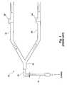
- FIG. 1schematically illustrates a conventional ventilation system that is typically used with patients who require assisted breathing during an illness, during a surgical procedure, or during recovery from a surgical procedure.
- the conventional ventilator system 10includes a tubular portion 12 that may be inserted into the trachea of a patient by known intubation procedures.
- the end 14 (i.e., the end most distant from the patient) of the tubular portion 12may be fitted with a Y-piece 16 that interconnects an inspiratory hose 18 and an expiratory hose 20 .
- Both the inspiratory hose 18 and expiratory hose 20may be connected to a ventilator machine (not shown), which delivers air into the breathing circuit through the inspiratory hose 18 .
- a one-way valve 22is positioned on the inspiratory hose 18 to prevent exhaled gas from entering the inspiratory hose 18 beyond the valve 22 .
- a similar one-way valve 24 on the expiratory hose 20limits movement of inspiratory gas into the expiratory hose 20 . Exhaled air flows passively into the expiratory hose 20 .
- Re-breathing circuit 30includes a tubular portion 32 insertable into the trachea of a patient by known intubation procedures. Gases may be provided to the patient from a ventilator machine (not shown) via an inspiratory hose 34 interconnected with tubular portion 32 by a Y-piece 36 . Tubular portion 32 and an expiratory hose 38 are also interconnected by Y-piece 36 . An additional length of hose 40 is provided in flow communication with the tubular portion 32 , between the tubular portion 32 and the Y-piece 36 , and acts as a deadspace for receiving exhaled gas.
- a three-way valve 42is constructed for intermittent actuation to .selectively direct the flow of gas into or from the additional length of hose 40 . That is, at one setting, the valve 42 allows inspiratory gas to enter the tubular portion 32 while preventing movement of the gas into the additional length of hose 40 . At a second setting, the valve 42 allows exhaled gas to enter into the expiratory hose 38 while preventing movement of gas into the additional length of hose 40 .
- the three-way valve 42directs exhaled air to enter into the additional length of hose 40 and causes the patient to re-breathe the exhaled air on the following breath thereby, effect re-breathing and to cause a change in the effective ventilation of the patient.
- Sensing and/or monitoring devicesmay be attached to the re-breathing ventilation circuit 30 between the additional length of hose 40 and the tubular portion 32 .
- the sensing and/or monitoring devicesmay include, for example, means 44 for detecting CO 2 concentration and means 46 for detecting respiratory flow parameters during inhalation and exhalation. These sensing and/or monitoring devices are typically associated with data recording and display equipment (not shown).
- One problem encountered in use of the conventional re-breathing systemis that the volume of the deadspace provided by the additional length of hose 40 is fixed and may not be adjusted.
- the amount of deadspace provided in the circuit for a small adult to effect re-breathingis the same amount of deadspace available for a large adult to effect re-breathing, and the resulting changes in CO 2 values for patients of different sizes or breathing capacities, derived from fixed-deadspace systems, can produce inadequate evaluation of a patient's cardiac output or pulmonary capillary blood flow.
- the three-way valve 42 of the systemis, expensive and significantly increases the cost of the ventilation device.
- the partial pressure of end-tidal carbon dioxide(Pet CO 2 ) is typically assumed to be equal to the partial pressure of carbon dioxide in the venous blood (Pv CO 2 ) of the patient, as well as to the partial pressure of carbon dioxide in the arterial blood (Pa CO 2 ) of the patient and to the partial pressure of carbon dioxide in the alveolar blood (P A CO 2 ) of the patient.
- the partial pressure of carbon dioxide in bloodmay be converted to the content of carbon dioxide in blood by means of a carbon dioxide dissociation curve.
- Total re-breathingis a somewhat undesirable means of measuring cardiac output or pulmonary capillary blood flow because the patient is required to breathe directly into and from a closed volume of gases (e.g., a bag) in order to produce the necessary effect. Moreover, it is typically impossible or very difficult for sedated or unconscious patients to actively participate in inhaling and exhaling into a fixed volume.
- Known partial re-breathing methodsare also advantageous over invasive techniques of measuring cardiac output or pulmonary capillary blood flow because partial re-breathing techniques are non-invasive, use the accepted Fick principle of calculation, are easily automated, and facilitate the calculation of cardiac output or pulmonary capillary blood flow from commonly monitored clinical signals.
- known partial re-breathing methodsare somewhat undesirable because they are a less accurate means of measuring the cardiac output or pulmonary capillary blood flow of non-intubated or spontaneously breathing patients, may only be conducted intermittently (usually at intervals of at least about four minutes), and result in an observed slight, but generally clinically insignificant, increase in arterial CO 2 levels.
- the apparatus typically employed in partial re-breathing techniquesdo not compensate for differences in patient size or breathing capacities.
- many devicesemploy expensive elements, such as three-way valves, which render the devices too expensive to be used as disposable units.
- adjustable deadspace re-breathing apparatusthat compensate for differences in the sizes or breathing capacities of different patients, that may be employed to provide a more accurate and continuous measurement of gases exhaled or inhaled by a patient, and are less expensive than conventional re-breathing apparatus and, thereby, facilitate use of the adjustable deadspace re-breathing apparatus as a single-use, or disposable, product.
- a more accurate method of estimating the cardiac output or pulmonary capillary blood flow of a patientare also be employed.
- the apparatus of the present inventionincludes a deadspace (i.e., volume of re-breathed gases), the volume of which can be adjusted without changing airway pressure.
- the inventionalso includes methods of adjusting the volume of deadspace to obtain a more accurate cardiac output or pulmonary capillary blood flow value.
- a modified form of the Fick Equationmay be employed with the adjustable deadspace volume to calculate the cardiac output or pulmonary capillary blood flow of the patient.
- the apparatus of the present inventionalso employs significantly less expensive elements of construction, thereby facilitating the use of the apparatus as a disposable product.
- the apparatus and methods of the present inventionapply a modified Fick Equation to calculate changes in partial pressure of carbon dioxide (P CO 2 ), flow, and concentration to evaluate the cardiac output or pulmonary capillary blood flow of a patient.
- V CO 2is the output of CO 2 from the lungs, or “CO 2 elimination”
- Ca CO 2 and Cv CO 2are the CO 2 contents of the arterial blood and venous blood CO 2 , respectively.
- ⁇ V CO 2is the change in CO 2 elimination in response to the change in ventilation
- ⁇ Ca CO 2is the change in the CO 2 content of the arterial blood of the patient in response to the change in ventilation
- ⁇ Pet CO 2is the change in the partial pressure of end-tidal CO 2
- sis the slope of a CO 2 dissociation curve known in the art.
- the foregoing differential equationassumes that there is no appreciable change in venous CO 2 concentration during the re-breathing episode, as demonstrated by Capek.
- a CO 2 dissociation curvewell known in the art, is used for determining CO 2 concentration based on partial pressure measurements.
- a deadspacewhich may comprise an additional 50-250 ml capacity of air passage, was provided in the ventilation circuit to decrease the effective alveolar ventilation.
- a ventilation apparatusis provided with a deadspace having an adjustable volume to provide a change in ventilation for determining accurate changes in CO 2 elimination and in partial pressure of end-tidal CO 2 that is commensurate with the requirements of patients of different sizes or breathing capacities.
- selectively adjustable deadspaceis provided into which the patient may exhale and from which the patient may inhale.
- the adjustable deadspace volume of the apparatusaccommodates a variety of patient sizes or breathing capacities (e.g., from a small adult to a large adult).
- the patientis provided with a volume of re-breathable gas commensurate with the patient's size or breathing capacity, which decreases the effective ventilation of the patient without changing the airway pressure of the patient. Because airway and intra-thoracic pressure are not affected by the re-breathing method of the present invention, cardiac output and pulmonary capillary blood flow are not significantly affected by re-breathing.
- the volume of deadspacemay be effectively lessened by selectively leaking exhaled gas from the ventilation system to atmosphere or to a closed receptacle means during inspiration.
- additional carbon dioxidemay be introduced into the deadspace to increase the effective deadspace volume.
- the ventilation apparatus of the present inventionincludes a tubular portion, which is also referred to as a conduit, to be placed in flow communication with the airway of a patient.
- the conduit of the ventilation apparatusmay also be placed in flow communication with or include an inhalation course and an exhalation course, each of which may include tubular members or conduits.
- the inhalation course and exhalation coursemay be interconnected in flow communication between a ventilator unit (i.e., a source of deliverable gas mechanically operated to assist the patient in breathing) and the patient.
- a ventilator unitneed not be used with the ventilation apparatus.
- inhaled air and exhaled airmay be taken from or vented to atmosphere.
- Other conventional equipment commonly used with ventilator units or used in ventilation of a patient, such as a breathing maskmay be used with the inventive ventilation apparatus.
- a pneumotachometer for measuring gas flow and a capnometer for measuring CO 2 partial pressureare provided along the flow path of the ventilation apparatus and, preferably, in proximity to the conduit, between the inhalation and exhalation portions of the ventilation apparatus and the patient's lungs.
- the pneumotachometer and capnometerdetect changes in gas concentrations and flow and are preferably in electrical communication with a computer programmed (i.e., by software or embedded hardware) to store and evaluate, in substantially real time, the measurements taken by the detection apparatus.
- Other forms of detection apparatusmay, alternatively or in combination with the pneumotachometer and the capnometer, be employed with the ventilation apparatus of the present invention.
- Deadspace having an adjustable volumeis provided in flow communication with the conduit.
- the deadspaceis in flow communication with the exhalation portion of the ventilation apparatus (e.g., the expiratory course), and may be in flow communication with the inhalation portion (e.g., the inspiratory course) of the ventilation apparatus.
- the volume of the deadspacemay be manually adjusted.
- electromechanical meansmay be operatively associated with the computer and with the deadspace to provide automatic adjustment of the volume of the deadspace in response to the patient's size or breathing capacity or in response to changes in the ventilation or respiration of the patient.
- a tracheal gas insufflation (“TGI”) apparatusis employed to provide the change in ventilation necessary to determine pulmonary CO 2 changes and to determine the cardiac output or pulmonary capillary blood flow of a patient in accordance with the differential Fick Equation disclosed previously.
- Tracheal gas insufflation apparatusare known, and are typically used to flush the deadspace of the alveoli of the lungs and to replace the deadspace with fresh gas infused through the TGI apparatus. That is, fresh gas is introduced to the central airway of a patient to improve alveolar ventilation and/or to minimize ventilatory pressure requirements.
- a TGI apparatusmay be interconnected, for example, by means of a catheter, with a ventilator apparatus and includes a means of introducing fresh gas into the breathing tube and into the lungs of the patient.
- the TGI apparatusmay be used in the methods of the present invention to determine baseline measurements of CO 2 elimination, partial pressure of end tidal CO 2 , or partial pressure of alveolar CO 2 during TGI.
- a deadspaceis formed by the patient's trachea and the endo-tracheal tube of the TGI apparatus, which facilitates measurement of a change in the partial pressure of CO 2 and in the amount of CO 2 eliminated by the patient that may be evaluated in accordance with the method of the present invention.
- the catheter of the TGI apparatusmay be variably positioned within the trachea of the patient to further adjust the deadspace volume.
- the deadspace provided by the apparatus of the present inventionfacilitates a rapid drop in CO 2 elimination, which thereafter increases slightly and slowly as the functional residual lung gas capacity, which is also referred to as functional residual capacity or “FRC”, equilibrates with the increase in the partial pressure of CO 2 in the alveoli.
- Partial pressure of end tidal CO 2increases at a slower rate than CO 2 elimination following the addition of deadspace, depending on alveolar deadspace and the cardiac output or pulmonary capillary blood flow of the patient, but then stabilizes to a new level.
- a “standard,” or baseline, breathing episodeis conducted for a selected period of time immediately preceding the introduction of a deadspace into the breathing circuit (i.e., immediately preceding re-breathing) and CO 2 elimination and partial pressure of end tidal CO 2 values are determined based on measurements made during the “standard” breathing event. These values are substituted as the values V CO 2 and Ca CO 2 in the differential Fick Equation.
- Carbon dioxide elimination and partial pressure of end tidal CO 2 valuesare also determined from measurements taken for a predetermined amount of time (e.g., approximately thirty seconds) following the introduction of a deadspace (i.e., after the onset of re-breathing) during partial re-breathing to provide the second set of values (subscript 2 values) in the differential Fick Equation.
- a predetermined amount of time at which the second set of values are obtainedmay be about the same as the duration of partial re-breathing.
- the period of time during which partial re-breathing occurs and during which normal breathing occursmay be determined by the individual patient's size and breathing capacity. Additionally, the period of time between a re-breathing episode and a subsequent normal breathing episode may vary between patients, depending on a particular patient's size and breathing capacity.
- Cardiac output or pulmonary capillary blood flowmay be determined in accordance with the method of the present invention by estimating the partial pressure of CO 2 in the alveoli or the content of the blood in capillaries that surround the alveoli of the lungs of a patient (Cc′ CO 2 ), or the alveolar CO 2 content (C A CO 2 ), rather than basing the cardiac output or pulmonary capillary blood flow determination on the partial pressure of end-tidal CO 2 , as is typically practiced in the art.
- Partial pressure values that are obtained from CO 2 measurementsare converted to a value for gas content in the blood using a CO 2 dissociation curve or equation, as known in the art.
- a more accurate cardiac output or pulmonary capillary blood flow valuecan be determined with alveolar CO 2 measurements than with partial pressure of end tidal CO 2 measurements.
- the accuracy of the cardiac output or pulmonary capillary blood flow measurementmay be increased by correcting CO 2 elimination values to account for flow of CO 2 into the functional residual capacity of the lungs, which is the volume of gas that remains in the lungs at the end of expiration.
- the cardiac output or pulmonary capillary blood flow of the patientmay then be determined by accounting for the functional residual capacity and by employing the values obtained in accordance with the method of the present invention, as well as other determined values, known values, estimated values, or any other values based on experiential data, such as by a computer processor in accordance with the programming thereof.
- cardiac output or pulmonary capillary blood flowmay be estimated without accounting for functional residual capacity.
- the ventilation apparatus of the present inventionmay also employ inexpensive yet accurate monitoring systems as compared to the systems currently used in the art.
- the methods of the inventionmay include the automatic adjustment of the deadspace volume of the apparatus to accommodate patients of different sizes or breathing capacities or changes in the ventilation or respiration of a patient, and provides consistent monitoring with modest recovery time. Further, the present apparatus and methods can be used with non-responsive, intubated patients and with non-intubated, responsive patients.
- FIG. 1is a schematic representation of a conventional ventilation system used to assist patient breathing
- FIG. 2is a schematic representation of a conventional re-breathing system
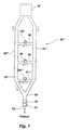
- FIG. 3is a schematic representation of a first embodiment of the ventilation apparatus of the present invention, illustrating a deadspace with an adjustably expandable volume;
- FIG. 4is a schematic representation of an alternative embodiment of the present invention, wherein the re-breathing circuit is constructed with an evacuation valve;
- FIGS. 5A-5Care schematic representations of another alternative embodiment of the present invention, wherein the inspiratory course and expiratory course of the breathing circuit are interconnected and the breathing circuit includes a two-way valve closeable across a flow path of the breathing circuit;
- FIG. 6is a schematic representation of an alternative embodiment similar to the embodiment shown in FIGS. 5A-5C, wherein the volumes of the inspiratory course and expiratory course of the breathing circuit are adjustably expandable;
- FIG. 7is a schematic representation of another embodiment of the invention, wherein a series of valves is provided along the length of the inspiratory course and expiratory course of the breathing circuit to provide a selectable volume of deadspace dependent upon the size, breathing capacity, or changes in the ventilation or respiration of the patient;
- FIGS. 8A and 8Bare schematic representations of another embodiment of the invention, wherein an evacuation valve is provided with a vent to atmosphere and to a receptacle or chamber, respectively;
- FIG. 9is a schematic representation of a breathing circuit of the present invention that includes a tracheal gas insufflation apparatus, which can be used to provide a volume of deadspace;
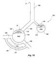
- FIG. 10is a schematic representation of human lungs, illustrating the concepts of parallel deadspace, alveolar deadspace and serial deadspace in the lungs of a patient;
- FIG. 11is a flow diagram that illustrates the calculations made in the method of the present invention to determine cardiac output or pulmonary capillary blood flow by employing the measured values during both normal breathing and partial re-breathing;
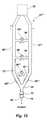
- FIG. 12is a schematic representation of a variation of the ventilation apparatus FIG. 7, including sections having selectively expandable volumes.
- FIG. 3illustrates a breathing circuit of the present invention, which is illustrated as a ventilation apparatus 50 , and which may be employed to determine the cardiac output of pulmonary capillary blood flow of a patient.
- Ventilation apparatus 50comprises a tubular airway 52 , which is also referred to as an airway conduit or simply as a conduit, that may be placed in flow communication with the trachea or lungs of the patient.
- the present ventilation apparatus 50may be placed in flow communication with the trachea of the patient by known intubation procedures or by positioning a breathing mask over the nose and/or mouth of the patient. Ventilation apparatus 50 may be used with unconscious or uncooperative patients needing ventilation assistance, and may be used with substantially equal efficacy with patients who are conscious.
- Ventilation apparatus 50may also include an inspiratory hose 54 , which is also referred to as an inspiratory course or as an inspiration portion of the breathing circuit, and an expiratory hose 56 , which is also referred to as an expiratory course or as an expiration portion of the breathing circuit, both of which are in substantial flow communication with tubular airway 52 .
- the inspiratory hose 54 and the expiratory hose 56may each be ventilated to atmosphere or operatively connect to a ventilator machine 55 to facilitate the delivery of air, breathing gases, or other breathing medium to the patient through the inspiratory hose 54 .
- the inspiratory hose 54 and expiratory hose 56may each be joined in flow communication with the tubular airway 52 by means of a Y-piece 58 .
- An additional length of conduit or hose 60which provides a deadspace volume for receiving exhaled gas from the patient, is preferably in flow communication with the tubular airway 52 . Both ends of the additional length of hose 60 are preferably in flow communication with tubular airway 52 .
- the additional length of hose 60is configured to be selectively expandable to readily enable the volume of deadspace to be adjusted commensurate with the size or breathing capacity of the patient, or commensurate with changes in the ventilation or respiration of the patient, such as an increased or decreased tidal volume or modified respiration rate. As suggested by FIG.
- selective expansion of the deadspacemay be accomplished by configuring the additional length of hose 60 to include an expandable section 62 made of, for example, a section of corrugated hose which can be lengthened or shortened by simply pulling or rushing the expandable section 62 substantially along its longitudinal axis 64 .
- the section of Corrugated hosewill preferably retain the length to which it is set until adjusted again.
- Other suitable means of providing adjustable expansion of the volume of the deadspace and, thus, methods of adjusting the volume of the deadspace of the breathing circuitare also available and within the scope of the present invention.
- a three-way valve 68may be disposed along the flow path of tubular airway 52 between the two ends of additional length of hose 60 and selectively positioned to direct inspiratory gas into a deadspace 70 comprised of the additional length of hose 60 upon inhalation, to selectively prevent exhaled gas from entering the deadspace 70 during normal breathing, or to direct exhaled gas into deadspace 70 during re-breathing so that the patient will re-breathe previously exhaled gases or a gas including CO 2 from the deadspace 70 .
- a flow meter 72such as a pneumotachometer, and a carbon dioxide sensor 74 , which is typically referred to as a capnometer, may be exposed to the flow path of the ventilation apparatus, preferably between the tubular airway 52 and the additional length of hose 60 .
- the flow meter 72 and carbon dioxide sensor 74are exposed to any air or gas that flows through ventilation apparatus 50 .
- the flow meter 72detects gas flow through the ventilation apparatus 50 .
- a flow meter 72 of a known typesuch as the differential-pressure type respiratory flow sensors manufactured by Novametrix Medical Systems Inc. (“Novametrix”) of Wallington, Conn. (e.g., the Pediatric/Adult Flow Sensor (Catalog No. 6717) or the Neonatal Flow sensor (Catalog No. 6718)), which may be operatively attached to a ventilation apparatus (not shown), as well as respiratory flow sensors based on other operating principles and manufactured or marketed by others, may be employed to measure the flow rates of the breathing patient.
- Novametrixthe differential-pressure type respiratory flow sensors manufactured by Novametrix Medical Systems Inc.
- the carbon dioxide sensor 74detects CO 2 levels and, therefore, facilitates a determination of changes in CO 2 levels that result from changes in the ventilation or respiration of the patient.
- the carbon dioxide sensor 74 and its associated airway adaptermay be an “on airway” sensor, a sampling sensor of the type which withdraws a side stream sample of gas for testing, or any other suitable type of carbon dioxide sensor.
- Exemplary carbon dioxide sensors and complementary airway adapterinclude, without limitation, the Pediatric/Adult Single Patient Use Airway Adapter (Catalog No. 6063), the Pediatric/Adult Reusable Airway Adapter (Catalog No. 7007), or the Neonatal/Pediatric Reusable Airway Adapter (Catalog No. 7053), which are manufactured by Novametrix.
- combined flow and carbon dioxide sensorsas known in the art, may be employed.
- the data obtained by the flow meter 72 and by the carbon dioxide sensor 74are preferably used to determine the cardiac output or pulmonary capillary blood flow of the patient. Accordingly, the flow meter 72 and carbon dioxide sensor 74 may be operatively associated with a computer 76 (e.g., by direct cable connection, wireless connection, etc.) programmed to store or analyze data from the flow meter 72 and the carbon dioxide sensor 74 and programmed to determine the cardiac output or pulmonary capillary blood flow of the patient from the stored or analyzed data.
- a computer 76e.g., by direct cable connection, wireless connection, etc.
- the differential Fick Equationrequires a change in the partial pressure of carbon dioxide and a change in carbon dioxide elimination to be induced in the patient in order to estimate the cardiac output or pulmonary capillary blood flow of the patient.
- the amount of CO 2 inhaled by the patientincreases, thereby facilitating the evaluation of increased CO 2 levels during a change in effective ventilation, as compared to the CO 2 levels of the patient's breathing during normal ventilation.
- the re-breathing ventilation apparatus 50 of the present inventionprovides the ability to selectively adjust the volume of deadspace from which air is re-breathed in accordance with the size or breathing capacity of the patient, or in response to changes in the ventilation or respiration of the patient.
- the deadspace volumemay be increased by an appropriate amount (e.g., 20 %).
- a threshold pressuree.g., 1 mm Hg
- a threshold percentage or fractione.g. 20% or 0.2
- the deadspace volumemay be decreased by an appropriate amount (e.g., 20%).
- the expense of using a three-way valvemay be eliminated by disposing an inexpensive two-way valve 78 ′ along the flow path of the additional length of hose 60 ′ and by positioning a flow restrictor 80 (e.g., a region of tubular airway 52 of decreased inner diameter) along tubular airway 52 between the inlet 82 and outlet 84 (i.e., the two ends) of the additional length of hose 60 ′.
- a flow restrictor 80e.g., a region of tubular airway 52 of decreased inner diameter
- the two-way valve 78 ′is placed in an open position so that the exhaled air, encountering the flow restrictor 80 , follows the course of less resistance into the deadspace 70 ′. Inhaled, re-breathed air similarly follows the course of least resistance and flows from the deadspace 70 ′.
- the optimal amount of air re-breathed by the patientmay depend upon the size, breathing capacity, or changes in the ventilation or respiration of the. patient, or on another factor, it may be desirable to adjust the deadspace 70 ′ at the expandable section 62 ′ to provide the necessary volume of deadspace for determining the cardiac output or pulmonary capillary blood flow of the patient.
- a shunt line 85is positioned between the inspiratory course 54 ′′ and the expiratory course 56 ′′ to provide a selectively-sized deadspace 70 ′′ in the re-breathing circuit.
- the inspiratory course 54 ′′ and expiratory course 56 ′′may comprise at least a part of the deadspace 70 ′′.
- a two-way shunt valve 86positioned in the flow path of the shunt line 85 , selectively directs the flow of inspired and expired gas, dependent upon whether the shunt valve 86 is placed in an open position or a closed position.
- exhaled air(represented by the shaded area) will enter the expiratory course 56 ′′.
- the shunt valve 86is placed in the closed position.
- exhaled gasmay fill a portion of the inspiratory course 54 ′′, substantially all of the expiratory course 56 ′′, and the shunt line 85 , all of which serve as the deadspace 70 ′′.
- the deadspace 70 ′′ in the embodiment shown in FIGS. 5A-5Cmay be rendered further expandable, as shown in FIG. 6, by structuring the inspiratory course 54 ′′ with an expandable section 90 positioned between the shunt line 85 and the Y-piece 58 , and/or by structuring the expiratory course 56 ′′ with an expandable section 92 positioned between the shunt line 85 and the Y-piece 58 .
- the deadspace 70 ′′can be selectively adjusted in accordance with the size or capacity of the patient, or responsive to operating conditions, by increasing or decreasing the volume of the expandable sections 90 , 92 of the inspiratory course 54 ′′ and expiratory course 56 ′′, respectively.
- Shunt line 85may similarly include a volume expandable section.
- any suitable adjustably expandable meansmay be employed as expandable sections 90 , 92 .
- the expandable sections 90 , 92may be fabricated from a corrugated plastic material, the length of which can be easily expanded or contracted and preferably substantially maintained until re-adjusted.
- the embodiment of FIG. 6provides a particularly simple and inexpensive construction that may render it easy-to-use and facilitate its use as a disposable product.
- a plurality of shunt lines 85 ′′′, 94 , 96is positioned between the inspiratory course 54 ′′′ and the expiratory course 56 ′′′, with each shunt line 85 ′′′, 94 , 96 including a two-way shunt valve 86 ′′′, 98 , 100 , respectively, disposed along the flow path thereof.
- the amount of deadspace 70 ′′′ desiredmay be selectively adjusted by permitting exhaled gas to move through any suitable combination of shunt lines 85 ′′′, 94 , 96 .
- shunt line 85 ′′′ and shunt line 94may be used as potential deadspace 70 ′′′.
- the shunt valves 86 ′′′, 98 associated with shunt line 85 ′′′ and shunt line 94may be placed in an open position to permit exhaled and re-breathable gas to fill the expiratory course 56 ′′′, the inspiratory course 54 ′′′ between shunt line 94 and the Y-piece 58 , shunt line 85 ′′′, and shunt line 94 .
- each shunt valve 86 ′′′, 98 , 100may be in electromechanical communication with the computer 76 (see FIG. 3) so that the computer may determine, from the carbon dioxide sensor 74 (see FIG. 3 ), for example, that a different volume of deadspace 70 ′′′ is needed. The computer 76 may then direct the opening or closing of one or more of the shunt valves 86 ′′′, 98 , 100 to provide a sufficient volume of deadspace 70 ′′′.
- the ventilation apparatus 50 ′′′may also include selectively expandable sections 90 ′′′, 92 ′′′ similar to those shown in FIG. 6 .
- expandable sections 90 ′′′ and 92 ′′′are illustrated as being disposed along inspiratory course 54 ′′′ and expiratory course 56 ′′′, sections of expandable volume may also be disposed along other portions of the potential deadspace of the breathing circuit, such as along any of shunt lines 85 ′′′, 94 , or 96 .
- the amount or volume of the deadspacehas been selectively adjustable by providing means for adjusting the volume of the deadspace, such as by providing length-expanding means. It may be equally appropriate, however, to provide a change in ventilation, as required by the differential Fick Equation, by leaking some of the exhaled gas out of the system during the inspiration phase of a breath or by increasing the level of CO 2 in the deadspace, both of which provide an effective change in the volume of deadspace.
- the ventilation apparatus 50 of the present inventionmay include an evacuation element or component.
- the evacuation elementmay include an evacuation line 106 in flow communication with at least the expiratory course 56 of the ventilation apparatus 50 .
- the evacuation elementincludes a structure that permits gas or another breathing medium to flow into or out of the ventilation apparatus 50 , such as an evacuation valve 108 , which is also referred to as a valve, that, when opened, allows exhaled gas to escape the ventilation apparatus 50 through an orifice 110 positioned at the end of the evacuation line 106 or permits gas to be introduced into the ventilation apparatus 50 .
- a valvemay be positioned in flow communication with ventilation apparatus 50 to facilitate the flow of gases therefrom.
- the volume of exhaled gas that should be leaked from the ventilation apparatus 50 or introduced therein during a re-breathing event, as well as the timing and duration of such leakage or introduction,may be determined by the computer 76 (see FIG. 3) in response to flow conditions, CO 2 conditions, the size or breathing capacity of the patient, or changes in the ventilation or breathing of the patient.
- the evacuation valve 108which may be in electromechanical communication with the computer 76 , may be selectively actuated by the computer 76 in accordance with the flow conditions, the CO 2 conditions, the size or breathing capacity of the patient, or changes in the ventilation or respiration of the patient.
- a chamber or receptacle 112such as an expandable bag, may be disposed along the evacuation line 106 or otherwise in flow communication with the evacuation valve 108 to receive the exhaled gas leaked from the ventilation circuit.
- FIG. 9schematically illustrates the use of a tracheal gas insufflation (TGI) apparatus 120 to provide the necessary deadspace in determining the cardiac output or pulmonary capillary blood flow of a patient.
- TGI apparatus 120are typically used to ventilate sick patients who require the injection of fresh gas into their central airway to improve alveolar ventilation.
- TGI apparatuscan be configured to provide continuous or phasic (e.g., only during inhalation) injections of gas.
- the TGI apparatussupplies gas, or an oxygen/gas mixture, to the lungs with every breath.
- the TGI apparatuscomprises an endotracheal tube 122 , which may be inserted into the trachea 124 of the patient by known intubation procedures.
- a catheter 126extends through the endotracheal tube 122 and into the patient's lungs, typically just above the carina. Gas or an oxygen/gas blend is provided from a gas source 128 and is directed through gas delivery tubing 130 into the catheter 126 .
- a flow meter 132 disposed along gas delivery tubing 130 and in flow communication therewithmay assist in determining the optimum amount of gas to be introduced into the lungs.
- An adaptor fitting 134may be used to connect a ventilation apparatus 136 , such as the type previously described in reference to FIGS. 1 - 8 (B), to the TGI apparatus 120 .
- the ventilation apparatus 136may include a Y-piece 58 from which an inspiratory course 54 and an expiratory course 56 extend.
- the ventilation apparatus 136may also include a flow meter 72 and a carbon dioxide sensor 74 disposed in flow communication therewith to collect data during normal breathing and during a re-breathing event.
- the endotracheal tube 122provides a volume of deadspace that may be required for re-breathing in addition to any deadspace volume provided by the ventilation apparatus 136 .
- the TGI apparatusi.e., the gas source 128 and flow meter 132
- the TGI apparatusis preferably turned off, the amount of insufflation reduced, or the TGI apparatus otherwise disabled. Exhaled air is thereby allowed to flow into the endotracheal tube 122 and, preferably, through the Y-piece 58 .
- the endotracheal tube 122 and ventilation apparatus 136 or portions thereofmay then serve as deadspace.
- the volume of deadspace provided by the TGI apparatus 120may be further increased or decreased, as necessary, by varying the depth to which the catheter 126 is positioned in the patient's trachea.
- a computer 76(see FIG. 3) to which the flow meter 72 and the carbon dioxide sensor 74 may be connected can be programmed to receive data from the flow meter 72 and the carbon dioxide sensor 74 and to analyze the data to determine or estimate the cardiac output or pulmonary capillary blood flow of the patient.
- the determination of cardiac output or pulmonary capillary blood flow for a given patientmay be based on data obtained with the flow monitor and the carbon dioxide sensor that are associated with the ventilation apparatus of the present invention.
- Raw flow and CO 2 signals from the flow monitor and the carbon dioxide sensormay be filtered to remove any artifacts, and the flow signals and CO 2 signals (e.g., data regarding partial pressure of CO 2 ) may be stored by the computer 76 .
- Each breath, or breathing cycle, of the patientmay be delineated, as known in the art, such as by continually monitoring the flow rate of the breathing of the patient.
- V CO 2the partial pressure of end-tidal CO 2 carbon dioxide elimination
- CO 2the fraction of inspired, or “mixed inspired”, CO 2
- the airway deadspaceare calculated.
- End-tidal CO 2is measured, as known in the art.
- Carbon dioxide eliminationis typically calculated as the integral of the respiratory flow over a breathing cycle (in milliliters) multiplied by the fraction of CO 2 over the entire breath.
- the fraction of inspired CO 2is the integral of CO 2 fraction times the air flow during inspiration, divided by the volume (in milliliters) of inspired gas.
- V CO 2 and Pet CO 2may be filtered by employing a median filter, which uses a median value from the most recent value of recorded V CO 2 and Pet CO 2 values and the two values that precede the most recent measured value, as known in the art.
- the V CO 2 valueis corrected to account for anatomic deadspace and alveolar deadspace.
- the lungs 150 of a patientmay be described as including a trachea 152 , two bronchi 154 and numerous alveoli 160 , 162 .
- the anatomic, or “serial”, deadspace of lungs 150includes the volume of the trachea 152 , bronchi 154 , and other components of lungs 150 which hold gases, but do not participate in gas exchange.
- the anatomic deadspaceexists approximately in the region located between arrows A and B.
- the so-called “shunted” bloodbypasses pulmonary capillaries by way of an intrapulmonary shunt 165 .
- Lungs 150typically include alveoli 160 that are in contact with blood flow and which can facilitate oxygenation of the blood, which are referred to as “perfused” alveoli, as well as unperfused alveoli 162 . Both perfused alveoli 160 and unperfused alveoli 162 may be ventilated. The volume of unperfused alveoli is the alveolar deadspace.
- Perfused alveoli 160are surrounded by and in contact with pulmonary capillaries 164 .
- oxygenated blood 166enters pulmonary capillaries 164
- oxygenated blood 168Blood that exits pulmonary capillaries 164 in the direction of arrow 171 is referred to as oxygenated blood 168 .
- a volume of gas known as the functional residual capacity (FRC) 170remains following exhalation.
- the alveolar CO 2is expired from a portion 172 of each of the alveoli 160 that is evacuated, or ventilated, during exhalation.
- the ventilated portion 178 of each of the unperfused alveoli 162may also include CO 2 .
- the CO 2 of ventilated portion 178 of each of the unperfused alveoli 162is not the result of O 2 and CO 2 exchange in that alveolus. Since the ventilated portion 178 of each of the unperfused alveoli 162 is ventilated in parallel with the perfused alveoli, ventilated portion 178 is typically referred to as “parallel” deadspace (PDS).
- Unperfused alveoli 162also include a FRC 176 , which includes a volume of gas that is not evacuated during a breath.
- FRCmay be estimated as a function of body weight and of the airway deadspace volume by the following equation:
- FRC-factoris either an experimentally determined value or is based on published data (e.g., “experiential” data) known in the art
- offset valueis a fixed constant which compensates for breathing masks or other equipment components that may add deadspace to the breathing circuit and, thereby, unacceptably skew the relationship between FRC and deadspace.
- the partial pressure of CO 2 in the parallel dead spacemay be calculated from the mixed inspired CO 2 (Vi CO 2 ) added to the product of the serial deadspace multiplied by the end tidal CO 2 of the previous breath (Pet CO 2 (n ⁇ 1)). Because the average partial pressure of CO 2 in the parallel deadspace is equal to the partial pressure of CO 2 in the parallel deadspace divided by the tidal volume (V t ) (i.e., the total volume of one respiratory cycle, or breath), the partial pressure of CO 2 in the parallel deadspace may be calculated on a breath-by-breath basis, as follows:
- P CO 2 PDS ( n )[ FRC /( FRC+V t )] ⁇ P CO 2 PDS ( n ⁇ 1)+( P bar ⁇ (([ Vi CO 2 +deadspace ⁇ ( Pet CO 2 ( n ⁇ 1)/ P bar )]/ V t ) ⁇ [ V t /( V t +FRC )])),
- (n)indicates a respiratory profile parameter (in this case, the partial pressure of CO 2 in the parallel deadspace, PC CO 2 PDS (n)) from the most recent breath and (n ⁇ 1) indicates a respiratory profile parameter from the previous breath.
- a respiratory profile parameterin this case, the partial pressure of CO 2 in the parallel deadspace, PC CO 2 PDS (n)
- the partial pressure of end-tidal CO 2which is assumed to be substantially equal to a weighted average of the partial pressure of CO 2 in all of the perfused and unperfused alveoli of a patient, may be calculated as follows:
- Pet CO 2® ⁇ P A CO 2 )+(1 +r ) P CO 2 PDS ,
- ris the perfusion ratio, which is calculated as the ratio of perfused alveolar ventilation to the total alveolar ventilation, or (V A ⁇ V PDS )/V A .
- the perfusion ratiomay be assumed to be about 0.95 or estimated, as known in the art.
- the perfusion ratiomay be determined by comparing arterial P CO 2 , which measurement may be obtained directly from arterial blood and assumed to be substantially the same as alveolar P CO 2 , to end tidal P CO 2 values by rearranging the previous equation as follows:
- alveolar CO 2 partial pressure of the patientmay be calculated.
- alveolar CO 2 partial pressureis calculated from the end-tidal CO 2 and the CO 2 in the parallel deadspace, as follows:
- P A CO 2[Pet CO 2 ⁇ (1 ⁇ r ) P CO 2 PDS ]/r.
- the alveolar CO 2 partial pressuremay then be converted to alveolar blood CO 2 content (C ACO 2 ) using an equation, such as the following:
- CA CO 2is the content of CO 2 in the alveolar blood and Hb is the concentration of hemoglobin in the blood of the pulmonary capillaries.
- Hbis the concentration of hemoglobin in the blood of the pulmonary capillaries.
- a hemoglobin count and, therefore, the hemoglobin concentrationare available and may be employed in calculating the CO 2 content. If a hemoglobin count or concentration is not available, another value that is based upon experiential or otherwise known data (e.g., 11.0 g/d1 ) may be employed in calculating the alveolar CO 2 content.
- the FRC and alveolar deadspace of the lungs of a patientmay be accounted for by multiplying the FRC by the change in end tidal partial pressure, such as by the following equation:
- V CO 2 correctedV CO 2 +FRC ⁇ Pet CO 2 /P bar ,
- ⁇ Pet CO 2is the breath-to-breath change in Pet CO 2 .
- Baseline Pet CO 2 and V CO 2 valueswhich are also referred to as “before re-breathing Pet CO 2 ” and “before re-breathing V CO 2 ”, respectively, occur during normal breathing and may be calculated as the average of a group of samples taken before the re-breathing process (e.g., the average of all samples between about 27 and 0 seconds before the start of a known re-breathing process).
- a V CO 2 valuewhich is typically referred to as “during re-breathing V CO 2 ”, is calculated during the re-breathing process.
- “During re-breathing V CO 2 ”may be calculated as the average V CO 2 during the interval of 25 to 30 seconds into the re-breathing period.
- the content of CO 2 in the alveolar blood during the re-breathing processmay then be calculated by employing a regression line, which facilitates prediction of the stable, or unchanging, content of alveolar CO 2 .
- P A CO 2is plotted against the breath-to-breath change in content of alveolar CO 2 ( ⁇ C A CO 2 ).
- a graph line that is defined by the plotted pointsis regressed, and the intersection between P A CO 2 and zero ⁇ C A CO 2 is the predicted stable content of alveolar CO 2 .
- the operation logic of an exemplary computer program that directs the execution of the method of the present inventionis briefly illustrated in the flow diagram of FIG. 11 .
- the computer 76(see FIG. 3) may be programmed to detect the end of an exhalation, at 200 , at which point the computer 76 collects data from the carbon dioxide sensor 74 and the flow meter 72 (see FIG. 3) and calculates Pet CO 2 , V CO 2 , the fraction of inspired CO 2 , and the airway deadspace values at 202 .
- the computer 76then calculates FRC, at 204 , according to the previously described equation, and in accordance with the program.
- the programalso directs the computer 76 to correct the V CO 2 value, at 206 , in accordance with the previously described equation.
- the CO 2 and V CO 2 valuesare re-calculated, at 210 , to provide data samples at evenly spaced times, not on the respiratory rate, which may be variable. This technique is typically referred to as “re-sampling” the data.
- the computer 76calculates the estimated partial pressure of CO 2 (P CO 2 ) in the parallel deadspace, at 212 , and calculates the estimated P CO 2 in the alveoli, at 214 , using the equations described previously. At that point, re-breathing is initiated, at 216 , and a deadspace volume is introduced in the re-breathing circuit.
- the computer 76in accordance with the programming thereof, collects data from the carbon dioxide sensor 74 and the flow meter 72 (see FIG. 3) and, from that data, determines the change in V CO 2 and the change in partial pressure of alveolar CO 2 (P A CO 2 ) induced by the introduction of the deadspace, at 218 .
- V CO 2is less than a predetermined minimum percentage (e.g., 20%) or exceeds a predetermined maximum percentage (e.g., 80%) of the baseline V CO 2 , or if the change in partial pressure of alveolar CO 2 is less than or exceeds predetermined threshold minimum and maximum pressures (e.g., 3 mm Hg or 20 mm Hg), determined at 220 , then the operator is notified to accordingly modify the volume of the partial re-breathing deadspace, at 222 .
- Baseline valuesmay then be canceled, at 224 or 232 , then recalculated, as suggested by arrow 226 or arrow 234 .
- the computer 76may signal mechanical or electromechanical means associated with the adjustable deadspace to automatically modify the volume thereof.
- the alveolar partial pressure (P A CO 2 )is converted by the software program to CO 2 content of the alveolar (pulmonary) capillaries (C A CO 2 or Cc′ CO 2 ).
- the change in the CO 2 content of the alveolar blood induced by having the patient re-breathe a volume of previously exhaled gases from the deadspaceis then calculated, at 236 . From these values, the cardiac output or pulmonary capillary blood flow of the patient may be calculated, at 238 , in accordance with the previously described equation or otherwise, as known in the art.
Landscapes
- Health & Medical Sciences (AREA)
- Life Sciences & Earth Sciences (AREA)
- Veterinary Medicine (AREA)
- Heart & Thoracic Surgery (AREA)
- Pulmonology (AREA)
- Hematology (AREA)
- Public Health (AREA)
- General Health & Medical Sciences (AREA)
- Engineering & Computer Science (AREA)
- Biomedical Technology (AREA)
- Animal Behavior & Ethology (AREA)
- Emergency Medicine (AREA)
- Pathology (AREA)
- Molecular Biology (AREA)
- Physiology (AREA)
- Surgery (AREA)
- Medical Informatics (AREA)
- Biophysics (AREA)
- Anesthesiology (AREA)
- Physics & Mathematics (AREA)
- Cardiology (AREA)
- Obesity (AREA)
- Measurement Of The Respiration, Hearing Ability, Form, And Blood Characteristics Of Living Organisms (AREA)
- Measuring Pulse, Heart Rate, Blood Pressure Or Blood Flow (AREA)
Abstract
Description


Claims (7)
Priority Applications (3)
| Application Number | Priority Date | Filing Date | Title |
|---|---|---|---|
| US09/777,629US6648832B2 (en) | 1996-12-19 | 2001-02-06 | Apparatus and method for non-invasively measuring cardiac output |
| US10/657,577US7018340B2 (en) | 1996-12-19 | 2003-09-08 | Apparatus and method for non-invasively measuring cardiac output |
| US11/346,913US20060129054A1 (en) | 1996-12-19 | 2006-02-03 | Methods for non-invasivelyestimating pulmonary capillary blood flow or cardiac output |
Applications Claiming Priority (3)
| Application Number | Priority Date | Filing Date | Title |
|---|---|---|---|
| US08/770,138US6306098B1 (en) | 1996-12-19 | 1996-12-19 | Apparatus and method for non-invasively measuring cardiac output |
| US09/262,510US6227196B1 (en) | 1996-12-19 | 1999-03-02 | Apparatus and method for non-invasively measuring cardiac output |
| US09/777,629US6648832B2 (en) | 1996-12-19 | 2001-02-06 | Apparatus and method for non-invasively measuring cardiac output |
Related Parent Applications (1)
| Application Number | Title | Priority Date | Filing Date |
|---|---|---|---|
| US09/262,510ContinuationUS6227196B1 (en) | 1996-12-19 | 1999-03-02 | Apparatus and method for non-invasively measuring cardiac output |
Related Child Applications (1)
| Application Number | Title | Priority Date | Filing Date |
|---|---|---|---|
| US10/657,577DivisionUS7018340B2 (en) | 1996-12-19 | 2003-09-08 | Apparatus and method for non-invasively measuring cardiac output |
Publications (2)
| Publication Number | Publication Date |
|---|---|
| US20010029339A1 US20010029339A1 (en) | 2001-10-11 |
| US6648832B2true US6648832B2 (en) | 2003-11-18 |
Family
ID=25087600
Family Applications (9)
| Application Number | Title | Priority Date | Filing Date |
|---|---|---|---|
| US08/770,138Expired - LifetimeUS6306098B1 (en) | 1996-12-19 | 1996-12-19 | Apparatus and method for non-invasively measuring cardiac output |
| US09/262,510Expired - LifetimeUS6227196B1 (en) | 1996-12-19 | 1999-03-02 | Apparatus and method for non-invasively measuring cardiac output |
| US09/767,363Expired - LifetimeUS6648831B2 (en) | 1996-12-19 | 2001-01-23 | Apparatus and method for non-invasively measuring cardiac output |
| US09/777,629Expired - LifetimeUS6648832B2 (en) | 1996-12-19 | 2001-02-06 | Apparatus and method for non-invasively measuring cardiac output |
| US10/657,577Expired - LifetimeUS7018340B2 (en) | 1996-12-19 | 2003-09-08 | Apparatus and method for non-invasively measuring cardiac output |
| US10/657,909Expired - LifetimeUS6908438B2 (en) | 1996-12-19 | 2003-09-08 | Apparatus and method for non-invasively measuring cardiac output |
| US11/120,103Expired - Fee RelatedUS7686012B2 (en) | 1996-12-19 | 2005-05-02 | Apparatus for non-invasively measuring cardiac output |
| US11/346,913AbandonedUS20060129054A1 (en) | 1996-12-19 | 2006-02-03 | Methods for non-invasivelyestimating pulmonary capillary blood flow or cardiac output |
| US12/702,596Expired - Fee RelatedUS8096297B2 (en) | 1996-12-19 | 2010-02-09 | Apparatus and method for non-invasively measuring caridac output |
Family Applications Before (3)
| Application Number | Title | Priority Date | Filing Date |
|---|---|---|---|
| US08/770,138Expired - LifetimeUS6306098B1 (en) | 1996-12-19 | 1996-12-19 | Apparatus and method for non-invasively measuring cardiac output |
| US09/262,510Expired - LifetimeUS6227196B1 (en) | 1996-12-19 | 1999-03-02 | Apparatus and method for non-invasively measuring cardiac output |
| US09/767,363Expired - LifetimeUS6648831B2 (en) | 1996-12-19 | 2001-01-23 | Apparatus and method for non-invasively measuring cardiac output |
Family Applications After (5)
| Application Number | Title | Priority Date | Filing Date |
|---|---|---|---|
| US10/657,577Expired - LifetimeUS7018340B2 (en) | 1996-12-19 | 2003-09-08 | Apparatus and method for non-invasively measuring cardiac output |
| US10/657,909Expired - LifetimeUS6908438B2 (en) | 1996-12-19 | 2003-09-08 | Apparatus and method for non-invasively measuring cardiac output |
| US11/120,103Expired - Fee RelatedUS7686012B2 (en) | 1996-12-19 | 2005-05-02 | Apparatus for non-invasively measuring cardiac output |
| US11/346,913AbandonedUS20060129054A1 (en) | 1996-12-19 | 2006-02-03 | Methods for non-invasivelyestimating pulmonary capillary blood flow or cardiac output |
| US12/702,596Expired - Fee RelatedUS8096297B2 (en) | 1996-12-19 | 2010-02-09 | Apparatus and method for non-invasively measuring caridac output |
Country Status (5)
| Country | Link |
|---|---|
| US (9) | US6306098B1 (en) |
| EP (1) | EP0999783B1 (en) |
| JP (2) | JP3521915B2 (en) |
| BR (1) | BR9714427A (en) |
| WO (1) | WO1998026710A1 (en) |
Cited By (29)
| Publication number | Priority date | Publication date | Assignee | Title |
|---|---|---|---|---|
| US20030045807A1 (en)* | 1997-11-03 | 2003-03-06 | Rich Daniels | Respiratory profile parameter determination method and apparatus |
| US20050124907A1 (en)* | 2000-02-22 | 2005-06-09 | Kai Kuck | Noninvasive effective lung volume estimation |
| US20050133033A1 (en)* | 2003-12-20 | 2005-06-23 | Drager Medical Ag & Co. | Device and process for metering breathing gas |
| US20050203432A1 (en)* | 1996-12-19 | 2005-09-15 | Orr Joseph A. | Apparatus and method for non-invasively measuring cardiac output |
| US7040315B1 (en)* | 1999-05-10 | 2006-05-09 | Aneo Ab | Arrangement for anaesthetising a living creature |
| US20060201503A1 (en)* | 2002-10-11 | 2006-09-14 | The Regents Of The University Of California | Bymixer apparatus and method for fast-response, adjustable measurement of mixed gas fractions in ventilation circuits |
| US20060243279A1 (en)* | 2004-12-06 | 2006-11-02 | Hinkle Allen J | Scented anesthesia breathing circuit |
| US20090205653A1 (en)* | 2005-04-29 | 2009-08-20 | Pawel Wisniewski | Breathing System |
| US20100307490A1 (en)* | 2007-11-14 | 2010-12-09 | Stefan Broborg | Patient cassette with variable patient circuit volume |
| US20110082380A1 (en)* | 2002-10-11 | 2011-04-07 | The Regents Of The University Of California | Bymixer Apparatus and Method for Fast-Response, Adjustable Measurement of Mixed Gas Fractions in Ventilation Circuits |
| USD653749S1 (en) | 2010-04-27 | 2012-02-07 | Nellcor Puritan Bennett Llc | Exhalation module filter body |
| US8113062B2 (en) | 2008-09-30 | 2012-02-14 | Nellcor Puritan Bennett Llc | Tilt sensor for use with proximal flow sensing device |
| USD655405S1 (en) | 2010-04-27 | 2012-03-06 | Nellcor Puritan Bennett Llc | Filter and valve body for an exhalation module |
| USD655809S1 (en) | 2010-04-27 | 2012-03-13 | Nellcor Puritan Bennett Llc | Valve body with integral flow meter for an exhalation module |
| US8425428B2 (en) | 2008-03-31 | 2013-04-23 | Covidien Lp | Nitric oxide measurements in patients using flowfeedback |
| US8439037B2 (en) | 2009-12-01 | 2013-05-14 | Covidien Lp | Exhalation valve assembly with integrated filter and flow sensor |
| US8439036B2 (en) | 2009-12-01 | 2013-05-14 | Covidien Lp | Exhalation valve assembly with integral flow sensor |
| US8469030B2 (en) | 2009-12-01 | 2013-06-25 | Covidien Lp | Exhalation valve assembly with selectable contagious/non-contagious latch |
| US8469031B2 (en) | 2009-12-01 | 2013-06-25 | Covidien Lp | Exhalation valve assembly with integrated filter |
| US8528554B2 (en) | 2008-09-04 | 2013-09-10 | Covidien Lp | Inverse sawtooth pressure wave train purging in medical ventilators |
| US8652064B2 (en) | 2008-09-30 | 2014-02-18 | Covidien Lp | Sampling circuit for measuring analytes |
| US8720442B2 (en) | 2008-09-26 | 2014-05-13 | Covidien Lp | Systems and methods for managing pressure in a breathing assistance system |
| US8776790B2 (en) | 2009-07-16 | 2014-07-15 | Covidien Lp | Wireless, gas flow-powered sensor system for a breathing assistance system |
| US9629971B2 (en) | 2011-04-29 | 2017-04-25 | Covidien Lp | Methods and systems for exhalation control and trajectory optimization |
| US9649458B2 (en) | 2008-09-30 | 2017-05-16 | Covidien Lp | Breathing assistance system with multiple pressure sensors |
| US9950135B2 (en) | 2013-03-15 | 2018-04-24 | Covidien Lp | Maintaining an exhalation valve sensor assembly |
| US20180318532A1 (en)* | 2016-05-03 | 2018-11-08 | Koninklijke Philips N.V. | Mechanical ventilation based on alveolar ventilation |
| US11324954B2 (en) | 2019-06-28 | 2022-05-10 | Covidien Lp | Achieving smooth breathing by modified bilateral phrenic nerve pacing |
| US11488703B2 (en) | 2013-04-25 | 2022-11-01 | Zoll Medical Corporation | Systems and methods to predict the chances of neurologically intact survival while performing CPR |
Families Citing this family (133)
| Publication number | Priority date | Publication date | Assignee | Title |
|---|---|---|---|---|
| AUPO322396A0 (en) | 1996-10-25 | 1996-11-21 | Robinson, Gavin J.B. Dr | A method of measuring cardiac output by pulmonary exchange of oxygen and an inert gas with the blood utilising a divided airway |
| US5778872A (en) | 1996-11-18 | 1998-07-14 | Medlis, Inc. | Artificial ventilation system and methods of controlling carbon dioxide rebreathing |
| US6575164B1 (en) | 1998-10-15 | 2003-06-10 | Ntc Technology, Inc. | Reliability-enhanced apparatus operation for re-breathing and methods of effecting same |
| US20070000494A1 (en) | 1999-06-30 | 2007-01-04 | Banner Michael J | Ventilator monitor system and method of using same |
| US6413226B1 (en) | 1999-10-22 | 2002-07-02 | Respironics, Inc. | Method and apparatus for determining cardiac output |
| US6540689B1 (en)* | 2000-02-22 | 2003-04-01 | Ntc Technology, Inc. | Methods for accurately, substantially noninvasively determining pulmonary capillary blood flow, cardiac output, and mixed venous carbon dioxide content |
| US6322514B1 (en) | 2000-03-13 | 2001-11-27 | Instrumentarium Corporation | Method for determining cardiac characteristics of subject |
| CA2304292C (en)* | 2000-03-31 | 2009-01-13 | Joseph Fisher | An improved rebreathing circuit to set and stabalize end tidal and arterial pco2 despite varying levels of minute ventilation |
| US7405158B2 (en) | 2000-06-28 | 2008-07-29 | Applied Materials, Inc. | Methods for depositing tungsten layers employing atomic layer deposition techniques |
| US6551929B1 (en) | 2000-06-28 | 2003-04-22 | Applied Materials, Inc. | Bifurcated deposition process for depositing refractory metal layers employing atomic layer deposition and chemical vapor deposition techniques |
| CA2346517A1 (en)* | 2001-05-04 | 2002-11-04 | Joseph Fisher | Improved method of maintaining constant arterial pco2 during increased minute ventilation and measurement of anatomic and alveolar dead space |
| DE60137191D1 (en) | 2001-03-05 | 2009-02-12 | Instrumentarium Corp | Method for the non-invasive determination of the condition of the circulation of an individual |
| US7135001B2 (en)* | 2001-03-20 | 2006-11-14 | Ric Investments, Llc | Rebreathing methods including oscillating, substantially equal rebreathing and nonrebreathing periods |
| EP1418968A4 (en)* | 2001-07-19 | 2009-11-18 | Resmed Ltd | Pressure support ventilation of patients |
| WO2003026721A2 (en) | 2001-09-24 | 2003-04-03 | Fukunaga Atsuo F | Breathing circuits having unconventional respiratory conduits and systems and methods for optimising utilisation of fresh gases |
| US7261105B2 (en) | 2001-09-24 | 2007-08-28 | F-Concepts Llc | Breathing circuits having unconventional respiratory conduits and systems and methods for optimizing utilization of fresh gases |
| EP1621224A3 (en)* | 2001-09-24 | 2006-04-19 | FUKUNAGA, Atsuo F. | Breathing circuit having an adjustable volume and length |
| US7717109B2 (en) | 2001-09-24 | 2010-05-18 | F-Concepts Llc | Breathing systems with post-inspiratory valve fresh gas flow input, components for implementing same, and methods of use |
| US6575918B2 (en) | 2001-09-27 | 2003-06-10 | Charlotte-Mecklenburg Hospital | Non-invasive device and method for the diagnosis of pulmonary vascular occlusions |
| WO2003033175A2 (en)* | 2001-10-18 | 2003-04-24 | University Of Miami | Continuous gas leakage for elimination of ventilator dead space |
| AU2003211060A1 (en)* | 2002-02-15 | 2003-09-09 | Eunoe, Inc. | Systems and methods for flow detection and measurement in csf shunts |
| US20030225339A1 (en)* | 2002-05-06 | 2003-12-04 | Respironics Novametrix | Methods for inducing temporary changes in ventilation for estimation of hemodynamic performance |
| SE0203427D0 (en) | 2002-11-20 | 2002-11-20 | Siemens Elema Ab | Passive gas sampling device |
| US6951216B2 (en) | 2002-12-19 | 2005-10-04 | Instrumentarium Corp. | Apparatus and method for use in non-invasively determining conditions in the circulatory system of a subject |
| US7886740B2 (en)* | 2003-01-28 | 2011-02-15 | Beth Israel Deaconess Medical Center, Inc. | Gas systems and methods for enabling respiratory stability |
| WO2004073482A2 (en)* | 2003-02-19 | 2004-09-02 | Joseph Fisher | Method of measuring cardiac related parameters non-invasively via the lung during spontaneous and controlled ventilation |
| EP3064242A1 (en) | 2003-04-28 | 2016-09-07 | Advanced Circulatory Systems Inc. | Ventilator and methods for treating head trauma and low blood circulation |
| US7836881B2 (en) | 2003-04-28 | 2010-11-23 | Advanced Circulatory Systems, Inc. | Ventilator and methods for treating head trauma and low blood circulation |
| US7766011B2 (en) | 2003-04-28 | 2010-08-03 | Advanced Circulatory Systems, Inc. | Positive pressure systems and methods for increasing blood pressure and circulation |
| US7646274B2 (en) | 2003-05-01 | 2010-01-12 | Uri Rapoport | Apparatus and method for non-invasive measurement of cardiac output |
| US7353825B2 (en)* | 2003-05-01 | 2008-04-08 | Axon Medical, Inc. | Apparatus and techniques for reducing the effects of general anesthetics |
| US7621272B2 (en)* | 2003-05-01 | 2009-11-24 | Anecare Laboratories, Inc. | Apparatus and techniques for reducing the effects of general anesthetics |
| US7455643B1 (en)* | 2003-07-07 | 2008-11-25 | Nellcor Puritan Bennett Ireland | Continuous non-invasive blood pressure measurement apparatus and methods providing automatic recalibration |
| FR2858236B1 (en) | 2003-07-29 | 2006-04-28 | Airox | DEVICE AND METHOD FOR SUPPLYING RESPIRATORY GAS IN PRESSURE OR VOLUME |
| US8011367B2 (en) | 2003-09-11 | 2011-09-06 | Advanced Circulatory Systems, Inc. | CPR devices and methods utilizing a continuous supply of respiratory gases |
| US6938618B2 (en)* | 2003-09-11 | 2005-09-06 | Advanced Circulatory Systems, Inc. | Bag-valve resuscitation for treatment of hypotention, head trauma, and cardiac arrest |
| JP2006034584A (en)* | 2004-07-27 | 2006-02-09 | Chest M I Inc | Dead space load device |
| US20080194980A1 (en)* | 2004-11-05 | 2008-08-14 | Nederlandse Organisatie Voor Toegepastnatuurwetenschappelijk Onderzoek | Method of and Unit for Determining the Cardiac Output of the Human Heart |
| WO2006119546A1 (en)* | 2005-05-06 | 2006-11-16 | Philip John Peyton | Pulmonary capnodynamic method for continuous non-invasive measurement of cardiac output |
| ES2318920B1 (en)* | 2005-05-13 | 2009-12-22 | German Peces-Barba Romero | NON-INVASIVE MEASUREMENT DEVICE FOR THE INTRINSECA POSITIVE PRESSURE PRESSURE VALUE EXISTING AT THE END OF THE EXPIRATION. |
| US20070129666A1 (en)* | 2005-11-22 | 2007-06-07 | Barton David F | System and method of modular integration of intravascular gas exchange catheter with respiratory monitor and ventilator |
| US7900626B2 (en)* | 2006-04-17 | 2011-03-08 | Daly Robert W | Method and system for controlling breathing |
| US8381732B2 (en)* | 2008-03-21 | 2013-02-26 | The Periodic Breathing Foundation, Llc | Nasal interface device |
| US7766857B2 (en)* | 2006-08-21 | 2010-08-03 | General Electric Company | Non-invasive determination of cardiac output, gas exchange and arterial blood gas concentration |
| US20080119753A1 (en)* | 2006-11-16 | 2008-05-22 | Cardiopulmonary Technologies, Inc. | Premature infant side-stream respiratory gas monitoring sensor |
| US10076268B1 (en)* | 2007-02-22 | 2018-09-18 | The United States Of America As Represented By The Administrator Of National Aeronautics And Space Administration | Portable unit for metabolic analysis |
| KR100874111B1 (en)* | 2007-03-05 | 2008-12-15 | 한국과학기술원 | Noninvasive Respiratory Characteristic Prediction Method and Indicator by Respiratory Analysis and Arterial Blood |
| JP5432728B2 (en) | 2007-03-16 | 2014-03-05 | コーニンクレッカ フィリップス エヌ ヴェ | Apparatus for evaluation of respiratory motion recording data and gas exchange data |
| US7795613B2 (en) | 2007-04-17 | 2010-09-14 | Toppan Printing Co., Ltd. | Structure with transistor |
| US8151790B2 (en) | 2007-04-19 | 2012-04-10 | Advanced Circulatory Systems, Inc. | Volume exchanger valve system and method to increase circulation during CPR |
| US9352111B2 (en) | 2007-04-19 | 2016-05-31 | Advanced Circulatory Systems, Inc. | Systems and methods to increase survival with favorable neurological function after cardiac arrest |
| US20080302365A1 (en)* | 2007-06-08 | 2008-12-11 | Cohen Eric D | Respiratory Mask |
| US8794235B2 (en)* | 2007-06-08 | 2014-08-05 | Ric Investments, Llc | System and method for treating ventilatory instability |
| US8763892B2 (en) | 2007-12-31 | 2014-07-01 | Oridon Medical 1987 Ltd. | Tube verifier |
| US8457706B2 (en) | 2008-05-16 | 2013-06-04 | Covidien Lp | Estimation of a physiological parameter using a neural network |
| JP5067698B2 (en)* | 2008-06-03 | 2012-11-07 | 日本光電工業株式会社 | Flow measurement system and biological information monitor |
| US20090326386A1 (en)* | 2008-06-30 | 2009-12-31 | Nellcor Puritan Bennett Ireland | Systems and Methods for Non-Invasive Blood Pressure Monitoring |
| US8660799B2 (en)* | 2008-06-30 | 2014-02-25 | Nellcor Puritan Bennett Ireland | Processing and detecting baseline changes in signals |
| US8398556B2 (en)* | 2008-06-30 | 2013-03-19 | Covidien Lp | Systems and methods for non-invasive continuous blood pressure determination |
| WO2010005343A2 (en)* | 2008-07-08 | 2010-01-14 | Marat Vadimovich Evtukhov | Rebreather respiratory loop failure detector |
| US8506498B2 (en) | 2008-07-15 | 2013-08-13 | Nellcor Puritan Bennett Ireland | Systems and methods using induced perturbation to determine physiological parameters |
| US8532751B2 (en)* | 2008-09-30 | 2013-09-10 | Covidien Lp | Laser self-mixing sensors for biological sensing |
| US9687161B2 (en)* | 2008-09-30 | 2017-06-27 | Nellcor Puritan Bennett Ireland | Systems and methods for maintaining blood pressure monitor calibration |
| US9301697B2 (en)* | 2008-09-30 | 2016-04-05 | Nellcor Puritan Bennett Ireland | Systems and methods for recalibrating a non-invasive blood pressure monitor |
| US9314168B2 (en)* | 2008-09-30 | 2016-04-19 | Nellcor Puritan Bennett Ireland | Detecting sleep events using localized blood pressure changes |
| US8434479B2 (en) | 2009-02-27 | 2013-05-07 | Covidien Lp | Flow rate compensation for transient thermal response of hot-wire anemometers |
| US8216136B2 (en) | 2009-03-05 | 2012-07-10 | Nellcor Puritan Bennett Llc | Systems and methods for monitoring heart rate and blood pressure correlation |
| US20100324431A1 (en)* | 2009-06-18 | 2010-12-23 | Nellcor Puritan Bennett Ireland | Determining Disease State Using An Induced Load |
| US9198582B2 (en)* | 2009-06-30 | 2015-12-01 | Nellcor Puritan Bennett Ireland | Determining a characteristic physiological parameter |
| US8290730B2 (en) | 2009-06-30 | 2012-10-16 | Nellcor Puritan Bennett Ireland | Systems and methods for assessing measurements in physiological monitoring devices |
| US20110021929A1 (en)* | 2009-07-27 | 2011-01-27 | Nellcor Puritan Bennett Ireland | Systems and methods for continuous non-invasive blood pressure monitoring |
| US8628477B2 (en)* | 2009-07-31 | 2014-01-14 | Nellcor Puritan Bennett Ireland | Systems and methods for non-invasive determination of blood pressure |
| US10004515B2 (en) | 2009-09-11 | 2018-06-26 | Tbi Innovations, Llc | Methods and devices to reduce damaging effects of concussive or blast forces on a subject |
| US10842502B2 (en) | 2009-09-11 | 2020-11-24 | Tbi Innovations, Llc | Devices and systems to mitigate traumatic brain and other injuries caused by concussive or blast forces |
| US9173660B2 (en) | 2009-09-11 | 2015-11-03 | Tbi Innovations, Llc | Methods and devices to reduce the likelihood of injury from concussive or blast forces |
| US11696766B2 (en) | 2009-09-11 | 2023-07-11 | Tbi Innovations, Llc | Methods and devices to reduce damaging effects of concussive or blast forces on a subject |
| US9168045B2 (en) | 2009-09-11 | 2015-10-27 | Tbi Innovations, Llc | Device to reduce SLOSH energy absorption and its damaging effects through the reduction of the flow of one or more outflow vessels of the cranium |
| US8985120B2 (en)* | 2009-09-11 | 2015-03-24 | Tbi Innovations, Llc | Method to reduce SLOSH energy absorption and its damaging effects through the reduction of inelastic collisions in an organism |
| US9220440B2 (en)* | 2009-09-21 | 2015-12-29 | Nellcor Puritan Bennett Ireland | Determining a characteristic respiration rate |
| US9066660B2 (en) | 2009-09-29 | 2015-06-30 | Nellcor Puritan Bennett Ireland | Systems and methods for high-pass filtering a photoplethysmograph signal |
| US8463347B2 (en)* | 2009-09-30 | 2013-06-11 | Nellcor Puritan Bennett Ireland | Systems and methods for normalizing a plethysmograph signal for improved feature analysis |
| US20110126832A1 (en)* | 2009-12-01 | 2011-06-02 | Nellcor Puritan Bennett Llc | Exhalation Valve Assembly |
| CA3117178C (en) | 2009-12-23 | 2023-06-13 | Fisher & Paykel Healthcare Limited | An interface and a method of supplying breathing gas |
| US9724266B2 (en) | 2010-02-12 | 2017-08-08 | Zoll Medical Corporation | Enhanced guided active compression decompression cardiopulmonary resuscitation systems and methods |
| US12016820B2 (en) | 2010-02-12 | 2024-06-25 | Zoll Medical Corporation | Enhanced guided active compression decompression cardiopulmonary resuscitation systems and methods |
| US9451887B2 (en) | 2010-03-31 | 2016-09-27 | Nellcor Puritan Bennett Ireland | Systems and methods for measuring electromechanical delay of the heart |
| US8898037B2 (en) | 2010-04-28 | 2014-11-25 | Nellcor Puritan Bennett Ireland | Systems and methods for signal monitoring using Lissajous figures |
| US8905019B2 (en)* | 2010-05-11 | 2014-12-09 | Carefusion 207, Inc. | Patient circuit integrity alarm using exhaled CO2 |
| US20130109993A1 (en)* | 2010-05-17 | 2013-05-02 | Koninklijke Philips Electronics N.V. | System and method for estimating upper airway resistance and lung compliance employing induced central apneas |
| US20110284007A1 (en)* | 2010-05-21 | 2011-11-24 | Pierre Peron | Positive pressure device |
| RU2013114446A (en)* | 2010-09-02 | 2014-10-10 | Конинклейке Филипс Электроникс Н.В. | INTUITIVE UNDERSTANDING OF VENTILATION EFFICIENCY |
| US8825428B2 (en) | 2010-11-30 | 2014-09-02 | Neilcor Puritan Bennett Ireland | Methods and systems for recalibrating a blood pressure monitor with memory |
| US9357934B2 (en) | 2010-12-01 | 2016-06-07 | Nellcor Puritan Bennett Ireland | Systems and methods for physiological event marking |
| US9259160B2 (en) | 2010-12-01 | 2016-02-16 | Nellcor Puritan Bennett Ireland | Systems and methods for determining when to measure a physiological parameter |
| US9049994B2 (en) | 2011-09-21 | 2015-06-09 | Siemens Medical Solutions Usa, Inc. | System for cardiac arrhythmia detection and characterization |
| US9060695B2 (en) | 2011-11-30 | 2015-06-23 | Covidien Lp | Systems and methods for determining differential pulse transit time from the phase difference of two analog plethysmographs |
| ITRM20110650A1 (en)* | 2011-12-06 | 2013-06-07 | Uni Campus Bio Medico Di Roma | APPARATUS FOR THE ESTIMATE OF THE HEART RATE. |
| US9364624B2 (en) | 2011-12-07 | 2016-06-14 | Covidien Lp | Methods and systems for adaptive base flow |
| KR20140116878A (en) | 2011-12-19 | 2014-10-06 | 레스큐시스템스 아이엔씨 | Systems and methods for therapeutic intrathoracic pressure regulation |
| US9498589B2 (en) | 2011-12-31 | 2016-11-22 | Covidien Lp | Methods and systems for adaptive base flow and leak compensation |
| US9022031B2 (en) | 2012-01-31 | 2015-05-05 | Covidien Lp | Using estimated carinal pressure for feedback control of carinal pressure during ventilation |
| US8844526B2 (en) | 2012-03-30 | 2014-09-30 | Covidien Lp | Methods and systems for triggering with unknown base flow |
| WO2013152415A1 (en)* | 2012-04-12 | 2013-10-17 | Michael Klein | Accurate tidal volume measurement |
| JP2015521059A (en)* | 2012-04-30 | 2015-07-27 | マイケル, クラインMichaelKLEIN | Novel method and apparatus for reaching and maintaining target arterial blood gas concentrations using a ramp sequence |
| US9144658B2 (en) | 2012-04-30 | 2015-09-29 | Covidien Lp | Minimizing imposed expiratory resistance of mechanical ventilator by optimizing exhalation valve control |
| US9492629B2 (en) | 2013-02-14 | 2016-11-15 | Covidien Lp | Methods and systems for ventilation with unknown exhalation flow and exhalation pressure |
| USD731049S1 (en) | 2013-03-05 | 2015-06-02 | Covidien Lp | EVQ housing of an exhalation module |
| USD736905S1 (en) | 2013-03-08 | 2015-08-18 | Covidien Lp | Exhalation module EVQ housing |
| USD731065S1 (en) | 2013-03-08 | 2015-06-02 | Covidien Lp | EVQ pressure sensor filter of an exhalation module |
| USD693001S1 (en) | 2013-03-08 | 2013-11-05 | Covidien Lp | Neonate expiratory filter assembly of an exhalation module |
| USD692556S1 (en) | 2013-03-08 | 2013-10-29 | Covidien Lp | Expiratory filter body of an exhalation module |
| USD701601S1 (en) | 2013-03-08 | 2014-03-25 | Covidien Lp | Condensate vial of an exhalation module |
| USD744095S1 (en) | 2013-03-08 | 2015-11-24 | Covidien Lp | Exhalation module EVQ internal flow sensor |
| USD731048S1 (en) | 2013-03-08 | 2015-06-02 | Covidien Lp | EVQ diaphragm of an exhalation module |
| US9981096B2 (en) | 2013-03-13 | 2018-05-29 | Covidien Lp | Methods and systems for triggering with unknown inspiratory flow |
| US8900169B2 (en) | 2013-03-15 | 2014-12-02 | Tbi Innovations, Llc | Methods and devices to reduce the likelihood of injury from concussive or blast forces |
| US20140358047A1 (en) | 2013-05-30 | 2014-12-04 | ResQSystems, Inc. | End-tidal carbon dioxide and amplitude spectral area as non-invasive markers of coronary perfusion pressure and arterial pressure |
| US10265495B2 (en) | 2013-11-22 | 2019-04-23 | Zoll Medical Corporation | Pressure actuated valve systems and methods |
| HUP1400421A2 (en)* | 2014-09-10 | 2016-03-29 | Gyarmathy Agnes Dr Pomozine | Instrument for adjusting and/or controlling co2 content of inhaled air |
| US11839717B2 (en)* | 2014-12-30 | 2023-12-12 | General Electric Company | Minute volume and carbon dioxide clearance as surrogates for EtCO2 in automatic ventilation |
| US9925346B2 (en) | 2015-01-20 | 2018-03-27 | Covidien Lp | Systems and methods for ventilation with unknown exhalation flow |
| EP4186548A1 (en) | 2015-04-02 | 2023-05-31 | Hill-Rom Services PTE. LTD. | Mask leakage detection for a respiratory device |
| USD775345S1 (en) | 2015-04-10 | 2016-12-27 | Covidien Lp | Ventilator console |
| CA3005557C (en) | 2015-11-16 | 2023-10-10 | Q30 Sports Science, Llc | Traumatic brain injury protection devices |
| US11224379B2 (en)* | 2016-02-18 | 2022-01-18 | Koninklljke Philips N.V. | Enhancement of respiratory parameter estimation and asynchrony detection algorithms via the use of central venous pressure manometry |
| JP2019513030A (en) | 2016-03-02 | 2019-05-23 | キューサーティー スポーツ サイエンス エルエルシーQ30 Sports Science,Llc | Method and apparatus for reducing the damaging effects of a shaking or blasting force on a subject |
| SG11202001113SA (en)* | 2017-08-08 | 2020-03-30 | Rostrum Medical Innovations Inc | Method and system for estimating the efficiency of the lungs of a patient |
| WO2021062466A1 (en)* | 2019-09-30 | 2021-04-08 | ResMed Pty Ltd | Acoustic analysis of a respiratory therapy system |
| US11896767B2 (en) | 2020-03-20 | 2024-02-13 | Covidien Lp | Model-driven system integration in medical ventilators |
| US12138393B2 (en)* | 2021-02-04 | 2024-11-12 | GE Precision Healthcare LLC | Ventilator systems and methods |
| WO2023057796A1 (en) | 2021-10-07 | 2023-04-13 | Arcelormittal | Process and apparatus for manufacturing a steel strip for electrical applications |
| SE2251373A1 (en)* | 2022-11-25 | 2023-10-17 | Sensebreath Ab | Lung function measurement arrangement |
| USD1034169S1 (en)* | 2024-03-06 | 2024-07-09 | Guilei Liu | Car door hook |
Citations (13)
| Publication number | Priority date | Publication date | Assignee | Title |
|---|---|---|---|---|
| US3910261A (en) | 1974-06-11 | 1975-10-07 | Bourns Inc | End-tidal gas analysis apparatus for respirators |
| US4192301A (en) | 1978-11-06 | 1980-03-11 | Hardwick Charles W | Re-breathing apparatus |
| US4239038A (en) | 1978-03-07 | 1980-12-16 | The Commonwealth Industrial Gases Limited | Manual resuscitators |
| US4265235A (en)* | 1979-05-11 | 1981-05-05 | Fukunaga Atsuo F | Anesthetic system |
| US4941476A (en) | 1986-09-29 | 1990-07-17 | Joseph Fisher | Non-invasive method and apparatus for measuring mixed venous blood carbon dioxide pressure (PVC02) and other physiological variables |
| US4947860A (en) | 1985-10-10 | 1990-08-14 | Joseph Fisher | Non-invasive method and apparatus for measuring mixed venous carbon dioxide pressure (PvCO2) and other physiological variables |
| US5299579A (en) | 1989-11-24 | 1994-04-05 | Minco Ab | Apparatus for examining a patient's pulmonary function |
| US5642726A (en) | 1994-10-18 | 1997-07-01 | Alcove Medical, Inc. | Reduced internal volume neonatal suction adaptor |
| WO1998012963A1 (en) | 1996-09-28 | 1998-04-02 | Technische Universität Dresden | Device to determine effective pulmonary blood flow |
| US5752509A (en)* | 1995-07-10 | 1998-05-19 | Burkhard Lachmann | Artificial ventilation system |
| US5782774A (en) | 1996-04-17 | 1998-07-21 | Imagyn Medical Technologies California, Inc. | Apparatus and method of bioelectrical impedance analysis of blood flow |
| US5836300A (en)* | 1996-03-11 | 1998-11-17 | Mault; James R. | Metabolic gas exchange and noninvasive cardiac output monitor |
| US6003511A (en)* | 1996-11-18 | 1999-12-21 | Medlis Corp. | Respiratory circuit terminal for a unilimb respiratory device |
Family Cites Families (17)
| Publication number | Priority date | Publication date | Assignee | Title |
|---|---|---|---|---|
| US3898987A (en)* | 1973-10-09 | 1975-08-12 | James O Elam | Breathing responsive device and method |
| US4016876A (en)* | 1973-11-06 | 1977-04-12 | Westinghouse Electric Corporation | Breathing apparatus |
| US4086923A (en)* | 1976-01-05 | 1978-05-02 | Melvyn Lane Henkin | Altitude conditioning method and apparatus |
| US4188946A (en)* | 1977-10-07 | 1980-02-19 | Rayburn Robert L | Controllable partial rebreathing anesthesia circuit and respiratory assist device |
| FI82367C (en)* | 1988-02-11 | 1991-03-11 | Instrumentarium Oy | TILL INTUBATIONSROER KOPPLAD SPIROMETER OCH PROVTAGNINGSFOERBINDNING I GASANALYSATOR. |
| US4949724A (en)* | 1988-12-23 | 1990-08-21 | Mahutte Cornelis K | Method and apparatus for continuous measurement of cardiac output |
| US5044363A (en)* | 1990-05-24 | 1991-09-03 | The United States Of America As Represented By The Department Of Health And Human Services | Adsorption system for scavenging anesthetic agents from waste gas released during surgical activity |
| JP2688453B2 (en)* | 1990-09-19 | 1997-12-10 | ザ ユニバーシティ オブ メルボルン | CO2 monitoring in arterial blood and closed loop control device |
| US5320093A (en)* | 1990-12-21 | 1994-06-14 | Brigham And Women's Hospital | Rapid anesthesia emergence system using closed-loop PCO2 control |
| US5800361A (en)* | 1995-02-06 | 1998-09-01 | Ntc Technology Inc. | Non-invasive estimation of arterial blood gases |
| US5971934A (en)* | 1996-10-04 | 1999-10-26 | Trustees Of The University Of Pennsylvania | Noninvasive method and apparatus for determining cardiac output |
| US5778872A (en) | 1996-11-18 | 1998-07-14 | Medlis, Inc. | Artificial ventilation system and methods of controlling carbon dioxide rebreathing |
| US5715862A (en)* | 1996-11-25 | 1998-02-10 | Carrier Corporation | Bidirectional flow control device |
| US6306098B1 (en) | 1996-12-19 | 2001-10-23 | Novametrix Medical Systems Inc. | Apparatus and method for non-invasively measuring cardiac output |
| US6217524B1 (en)* | 1998-09-09 | 2001-04-17 | Ntc Technology Inc. | Method of continuously, non-invasively monitoring pulmonary capillary blood flow and cardiac output |
| JP2000107144A (en)* | 1998-10-01 | 2000-04-18 | Nippon Colin Co Ltd | Blood pressure monitoring device |
| US6971934B1 (en)* | 2004-12-22 | 2005-12-06 | The United States Of America As Represented By The Secretary Of The Navy | Autonomous liquid filled buoy |
- 1996
- 1996-12-19USUS08/770,138patent/US6306098B1/ennot_activeExpired - Lifetime
- 1997
- 1997-12-18JPJP52805998Apatent/JP3521915B2/ennot_activeExpired - Lifetime
- 1997-12-18WOPCT/US1997/024263patent/WO1998026710A1/enactiveApplication Filing
- 1997-12-18BRBR9714427-4Apatent/BR9714427A/ennot_activeIP Right Cessation
- 1997-12-18EPEP97953582.0Apatent/EP0999783B1/ennot_activeExpired - Lifetime
- 1999
- 1999-03-02USUS09/262,510patent/US6227196B1/ennot_activeExpired - Lifetime
- 2001
- 2001-01-23USUS09/767,363patent/US6648831B2/ennot_activeExpired - Lifetime
- 2001-02-06USUS09/777,629patent/US6648832B2/ennot_activeExpired - Lifetime
- 2003
- 2003-09-08USUS10/657,577patent/US7018340B2/ennot_activeExpired - Lifetime
- 2003-09-08USUS10/657,909patent/US6908438B2/ennot_activeExpired - Lifetime
- 2003-11-19JPJP2003388689Apatent/JP3955011B2/ennot_activeExpired - Lifetime
- 2005
- 2005-05-02USUS11/120,103patent/US7686012B2/ennot_activeExpired - Fee Related
- 2006
- 2006-02-03USUS11/346,913patent/US20060129054A1/ennot_activeAbandoned
- 2010
- 2010-02-09USUS12/702,596patent/US8096297B2/ennot_activeExpired - Fee Related
Patent Citations (13)
| Publication number | Priority date | Publication date | Assignee | Title |
|---|---|---|---|---|
| US3910261A (en) | 1974-06-11 | 1975-10-07 | Bourns Inc | End-tidal gas analysis apparatus for respirators |
| US4239038A (en) | 1978-03-07 | 1980-12-16 | The Commonwealth Industrial Gases Limited | Manual resuscitators |
| US4192301A (en) | 1978-11-06 | 1980-03-11 | Hardwick Charles W | Re-breathing apparatus |
| US4265235A (en)* | 1979-05-11 | 1981-05-05 | Fukunaga Atsuo F | Anesthetic system |
| US4947860A (en) | 1985-10-10 | 1990-08-14 | Joseph Fisher | Non-invasive method and apparatus for measuring mixed venous carbon dioxide pressure (PvCO2) and other physiological variables |
| US4941476A (en) | 1986-09-29 | 1990-07-17 | Joseph Fisher | Non-invasive method and apparatus for measuring mixed venous blood carbon dioxide pressure (PVC02) and other physiological variables |
| US5299579A (en) | 1989-11-24 | 1994-04-05 | Minco Ab | Apparatus for examining a patient's pulmonary function |
| US5642726A (en) | 1994-10-18 | 1997-07-01 | Alcove Medical, Inc. | Reduced internal volume neonatal suction adaptor |
| US5752509A (en)* | 1995-07-10 | 1998-05-19 | Burkhard Lachmann | Artificial ventilation system |
| US5836300A (en)* | 1996-03-11 | 1998-11-17 | Mault; James R. | Metabolic gas exchange and noninvasive cardiac output monitor |
| US5782774A (en) | 1996-04-17 | 1998-07-21 | Imagyn Medical Technologies California, Inc. | Apparatus and method of bioelectrical impedance analysis of blood flow |
| WO1998012963A1 (en) | 1996-09-28 | 1998-04-02 | Technische Universität Dresden | Device to determine effective pulmonary blood flow |
| US6003511A (en)* | 1996-11-18 | 1999-12-21 | Medlis Corp. | Respiratory circuit terminal for a unilimb respiratory device |
Non-Patent Citations (15)
| Title |
|---|
| Abstract FC 11 of article entitled "a Non-Invasive Technique for Measurement of Lung Perfusion" by H. Blomquist et al., published in "Monitoring, Computer, Instrumentation", Intensive Care Medicine (1986) 12:172. |
| Article entitled "Noninvasive Measurement of Cardiac Output Using Partial Carbon-Dioxide Rebreathing" by John Michael Capek (title, introductory pages and pp. 127-132)-Printed by UMI Dissertation Services-Dec. 1988. |
| Article entitled "Noninvasive Measurement of Cardiac Output Using Partial CO2 Rebreathing" by John M. Capek and Rob J. Roy (pp. 653-661)- Printed in IEEE Transactions On Biomedical Engineering, vol. 35, No. 9-Sep. 1988. |
| Article entitled "Noninvasive Pulmonary Blood Flow for Optimal Peep" by A. Gedeon, ICOR AB, Ulvsundavägen 178 B, S-161 30 Bromma, Sweden (pp. 49-58). |
| Article entitled "Non-invasive pulmonary blood flow measurement by means of CO2 analysis of expiratory gases" by Bosman, R.J., et al., Intensive Care Med (1991) 17:98-102. |
| de Abreu, M. Gama, et al., Reliability of the Partial CO2 Rebreathing Technique for Measurement of Cardiac Output, Proceedings RC IEEE-EMBS & 14th BMESI-1995 (3 pages). |
| de Abreu, Marcel Gama, et al., Partial carbon dioxide breathing: A reliable technique for noninvasive measurement of nonshunted pulmonary capillary blood flow, Crit Care Med 1997, vol. 25, No. 4, pp. 675-683. |
| de Abreu, Marcelo Gama, et al., Is the Partial CO2 Rebreathing Technique a Useful Tool for Trending Pulmonary Capillary Blood Flow During Adjustments of Peep?, 1 page. |
| de Abreu, Marcelo Gama, et al., Measurement of Pulmonary Capillary Blood Flow for Trending Mixed Venous Blood Oxygen Saturation and Oxygen Delivery, 1 page. |
| Gedeon, A., et al., A new method for noninvasive bedside determination of pulmonary blood flow, Medical & Biological Engineering & Computing, Jul. 1980, pp. 411-418. |
| Gedeon, A., et al., Noninvasive Cardiac Output Determined with a New Method Based on Gas Exchange Measurements and Carbon Dioxide Rebreathing: A Study in Animals/Pigs, Journal of Clinical Monitoring, vol. 8, No. 4, Oct. 1992, pp. 267-278. |
| Osterlund, B., et al., A new method of using gas exchange measurements for the noninvasive determination of cardiac output: clinical experiences in adults following cardiac surgery, Acta Anaesthesiologica Scandinavica 39 (1995), pp. 727-732. |
| Sackner, Marvin A., Measurement of cardiac output by alveolar gas exchange, Handbook of Physiology˜The Respiratory System IV, Chapter 13: Pulmonary Capillary Blood Flow, pp. 233-255. |
| Sackner, Marvin A., Measurement of cardiac output by alveolar gas exchange, Handbook of Physiology<~>The Respiratory System IV, Chapter 13: Pulmonary Capillary Blood Flow, pp. 233-255. |
| Winkler, Tilo, et al., Pulmonary Capillary Blood Flow by Partial CO2 Rebreathing: A Simulation Study Using a Bicompartmental Model of Gas Exchange, 1 page. |
Cited By (47)
| Publication number | Priority date | Publication date | Assignee | Title |
|---|---|---|---|---|
| US8096297B2 (en) | 1996-12-19 | 2012-01-17 | Ric Investments, Llc | Apparatus and method for non-invasively measuring caridac output |
| US20100132710A1 (en)* | 1996-12-19 | 2010-06-03 | Ric Investments, Llc | Apparatus and method for non-invasively measuring caridac output |
| US20050203432A1 (en)* | 1996-12-19 | 2005-09-15 | Orr Joseph A. | Apparatus and method for non-invasively measuring cardiac output |
| US7686012B2 (en) | 1996-12-19 | 2010-03-30 | Ric Investments, Llc | Apparatus for non-invasively measuring cardiac output |
| US7662106B2 (en)* | 1997-11-03 | 2010-02-16 | Ric Investments, Llc. | Respiratory profile parameter determination apparatus |
| US8251914B2 (en) | 1997-11-03 | 2012-08-28 | Ric Investments, Llc | Respiratory profile parameter determination method and apparatus |
| US20100097380A1 (en)* | 1997-11-03 | 2010-04-22 | Ric Investments, Llc | Respiratory profile parameter determination method and apparatus |
| US20030045807A1 (en)* | 1997-11-03 | 2003-03-06 | Rich Daniels | Respiratory profile parameter determination method and apparatus |
| US7040315B1 (en)* | 1999-05-10 | 2006-05-09 | Aneo Ab | Arrangement for anaesthetising a living creature |
| US7699788B2 (en)* | 2000-02-22 | 2010-04-20 | Ric Investments, Llc. | Noninvasive effective lung volume estimation |
| US20050124907A1 (en)* | 2000-02-22 | 2005-06-09 | Kai Kuck | Noninvasive effective lung volume estimation |
| US8820325B2 (en) | 2002-10-11 | 2014-09-02 | The Regents Of The University Of California | Bymixer apparatus and method for fast-response, adjustable measurement of mixed gas fractions in ventilation circuits |
| US7793659B2 (en)* | 2002-10-11 | 2010-09-14 | The Regents Of The University Of California | Bymixer apparatus and method for fast-response, adjustable measurement of mixed gas fractions in ventilation circuits |
| US20060201503A1 (en)* | 2002-10-11 | 2006-09-14 | The Regents Of The University Of California | Bymixer apparatus and method for fast-response, adjustable measurement of mixed gas fractions in ventilation circuits |
| US20110082380A1 (en)* | 2002-10-11 | 2011-04-07 | The Regents Of The University Of California | Bymixer Apparatus and Method for Fast-Response, Adjustable Measurement of Mixed Gas Fractions in Ventilation Circuits |
| US6929006B2 (en)* | 2003-12-20 | 2005-08-16 | Dräger Medical AG & Co. KGaA | Device and process for metering breathing gas |
| US20050133033A1 (en)* | 2003-12-20 | 2005-06-23 | Drager Medical Ag & Co. | Device and process for metering breathing gas |
| US20060243279A1 (en)* | 2004-12-06 | 2006-11-02 | Hinkle Allen J | Scented anesthesia breathing circuit |
| US20090205653A1 (en)* | 2005-04-29 | 2009-08-20 | Pawel Wisniewski | Breathing System |
| US8281785B2 (en)* | 2005-04-29 | 2012-10-09 | Pawel Wisniewski | Breathing system |
| US20100307490A1 (en)* | 2007-11-14 | 2010-12-09 | Stefan Broborg | Patient cassette with variable patient circuit volume |
| US8640703B2 (en)* | 2007-11-14 | 2014-02-04 | Maquet Critical Care Ab | Patient cassette with variable patient circuit volume |
| US8425428B2 (en) | 2008-03-31 | 2013-04-23 | Covidien Lp | Nitric oxide measurements in patients using flowfeedback |
| US8528554B2 (en) | 2008-09-04 | 2013-09-10 | Covidien Lp | Inverse sawtooth pressure wave train purging in medical ventilators |
| US8720442B2 (en) | 2008-09-26 | 2014-05-13 | Covidien Lp | Systems and methods for managing pressure in a breathing assistance system |
| US9649458B2 (en) | 2008-09-30 | 2017-05-16 | Covidien Lp | Breathing assistance system with multiple pressure sensors |
| US8652064B2 (en) | 2008-09-30 | 2014-02-18 | Covidien Lp | Sampling circuit for measuring analytes |
| US8113062B2 (en) | 2008-09-30 | 2012-02-14 | Nellcor Puritan Bennett Llc | Tilt sensor for use with proximal flow sensing device |
| US8776790B2 (en) | 2009-07-16 | 2014-07-15 | Covidien Lp | Wireless, gas flow-powered sensor system for a breathing assistance system |
| US9987457B2 (en) | 2009-12-01 | 2018-06-05 | Covidien Lp | Exhalation valve assembly with integral flow sensor |
| US8469030B2 (en) | 2009-12-01 | 2013-06-25 | Covidien Lp | Exhalation valve assembly with selectable contagious/non-contagious latch |
| US8469031B2 (en) | 2009-12-01 | 2013-06-25 | Covidien Lp | Exhalation valve assembly with integrated filter |
| US8439037B2 (en) | 2009-12-01 | 2013-05-14 | Covidien Lp | Exhalation valve assembly with integrated filter and flow sensor |
| US9205221B2 (en) | 2009-12-01 | 2015-12-08 | Covidien Lp | Exhalation valve assembly with integral flow sensor |
| US8439036B2 (en) | 2009-12-01 | 2013-05-14 | Covidien Lp | Exhalation valve assembly with integral flow sensor |
| USD655809S1 (en) | 2010-04-27 | 2012-03-13 | Nellcor Puritan Bennett Llc | Valve body with integral flow meter for an exhalation module |
| USD655405S1 (en) | 2010-04-27 | 2012-03-06 | Nellcor Puritan Bennett Llc | Filter and valve body for an exhalation module |
| USD653749S1 (en) | 2010-04-27 | 2012-02-07 | Nellcor Puritan Bennett Llc | Exhalation module filter body |
| US9629971B2 (en) | 2011-04-29 | 2017-04-25 | Covidien Lp | Methods and systems for exhalation control and trajectory optimization |
| US10850056B2 (en) | 2011-04-29 | 2020-12-01 | Covidien Lp | Methods and systems for exhalation control and trajectory optimization |
| US11638796B2 (en) | 2011-04-29 | 2023-05-02 | Covidien Lp | Methods and systems for exhalation control and trajectory optimization |
| US9950135B2 (en) | 2013-03-15 | 2018-04-24 | Covidien Lp | Maintaining an exhalation valve sensor assembly |
| US11488703B2 (en) | 2013-04-25 | 2022-11-01 | Zoll Medical Corporation | Systems and methods to predict the chances of neurologically intact survival while performing CPR |
| US20180318532A1 (en)* | 2016-05-03 | 2018-11-08 | Koninklijke Philips N.V. | Mechanical ventilation based on alveolar ventilation |
| US10881821B2 (en)* | 2016-05-03 | 2021-01-05 | Koninklijke Philips N.V. | Mechanical ventilation based on alveolar ventilation |
| US11324954B2 (en) | 2019-06-28 | 2022-05-10 | Covidien Lp | Achieving smooth breathing by modified bilateral phrenic nerve pacing |
| US12036409B2 (en) | 2019-06-28 | 2024-07-16 | Covidien Lp | Achieving smooth breathing by modified bilateral phrenic nerve pacing |
Also Published As
| Publication number | Publication date |
|---|---|
| EP0999783A1 (en) | 2000-05-17 |
| JP2001506158A (en) | 2001-05-15 |
| JP3521915B2 (en) | 2004-04-26 |
| US20010031928A1 (en) | 2001-10-18 |
| US20010029339A1 (en) | 2001-10-11 |
| US20050203432A1 (en) | 2005-09-15 |
| JP3955011B2 (en) | 2007-08-08 |
| US7018340B2 (en) | 2006-03-28 |
| US6648831B2 (en) | 2003-11-18 |
| WO1998026710A1 (en) | 1998-06-25 |
| US8096297B2 (en) | 2012-01-17 |
| US20040059239A1 (en) | 2004-03-25 |
| US6306098B1 (en) | 2001-10-23 |
| JP2005152001A (en) | 2005-06-16 |
| BR9714427A (en) | 2000-04-25 |
| US20060129054A1 (en) | 2006-06-15 |
| EP0999783A4 (en) | 2009-05-06 |
| US20100132710A1 (en) | 2010-06-03 |
| EP0999783B1 (en) | 2013-05-22 |
| US7686012B2 (en) | 2010-03-30 |
| US6908438B2 (en) | 2005-06-21 |
| US6227196B1 (en) | 2001-05-08 |
| US20040049113A1 (en) | 2004-03-11 |
Similar Documents
| Publication | Publication Date | Title |
|---|---|---|
| US6648832B2 (en) | Apparatus and method for non-invasively measuring cardiac output | |
| US6238351B1 (en) | Method for compensating for non-metabolic changes in respiratory or blood gas profile parameters | |
| US6217524B1 (en) | Method of continuously, non-invasively monitoring pulmonary capillary blood flow and cardiac output | |
| US6241681B1 (en) | Methods of measuring cardiac output using a non-invasively estimated intrapulmonary shunt fraction | |
| US7074196B2 (en) | Algorithms, systems, and methods for estimating carbon dioxide stores, transforming respiratory gas measurements, and obtaining accurate noninvasive pulmonary capillary blood flow and cardiac output measurements | |
| US9173595B2 (en) | Non-invasive method and apparatus for optimizing the respiration of atelectatic lungs | |
| US7766857B2 (en) | Non-invasive determination of cardiac output, gas exchange and arterial blood gas concentration | |
| US6200271B1 (en) | Bi-directional partial re-breathing method | |
| US6059732A (en) | ISO-volumetric method of measuring carbon dioxide elimination | |
| US6210342B1 (en) | Bi-directional partial re-breathing method | |
| US20070123792A1 (en) | System and method for determining airway obstruction | |
| US7070569B2 (en) | Non-invasive determination of conditions in the circulatory system of a subject | |
| US20210244900A1 (en) | Method for operating a ventilator for artificial ventilation of a patient, and such a ventilator | |
| US20250269129A1 (en) | Method and device for measuring volumetric capnometry, oximetry and functional residual capacity (frc) |
Legal Events
| Date | Code | Title | Description |
|---|---|---|---|
| STCF | Information on status: patent grant | Free format text:PATENTED CASE | |
| AS | Assignment | Owner name:RESPIRONICS NOVAMETRIX, INC., CONNECTICUT Free format text:CHANGE OF NAME;ASSIGNOR:NOVAMETRIX MEDICAL SYSTEMS, INC.;REEL/FRAME:015271/0590 Effective date:20020412 | |
| AS | Assignment | Owner name:RESPIRONICS NOVAMETRIX, LLC.,CONNECTICUT Free format text:MERGER;ASSIGNOR:RESPIRONICS NOVAMETRIX, INC.;REEL/FRAME:016301/0886 Effective date:20021216 Owner name:RESPIRONICS NOVAMETRIX, LLC., CONNECTICUT Free format text:MERGER;ASSIGNOR:RESPIRONICS NOVAMETRIX, INC.;REEL/FRAME:016301/0886 Effective date:20021216 | |
| AS | Assignment | Owner name:RESPIRONICS, INC.,PENNSYLVANIA Free format text:DIVIDEND FROM SUBSIDIARY TO PARENT;ASSIGNOR:RESPIRONICS NOVAMETRIX, LLC.;REEL/FRAME:016637/0931 Effective date:20030101 Owner name:RESPIRONICS, INC., PENNSYLVANIA Free format text:DIVIDEND FROM SUBSIDIARY TO PARENT;ASSIGNOR:RESPIRONICS NOVAMETRIX, LLC.;REEL/FRAME:016637/0931 Effective date:20030101 | |
| AS | Assignment | Owner name:RIC INVESTMENTS, INC.,DELAWARE Free format text:ASSIGNMENT OF ASSIGNORS INTEREST;ASSIGNOR:RESPIRONICS, INC.;REEL/FRAME:016649/0763 Effective date:20020627 Owner name:RIC INVESTMENTS, LLC.,DELAWARE Free format text:CHANGE OF NAME;ASSIGNOR:RIC INVESTMENTS, INC.;REEL/FRAME:016653/0709 Effective date:20040317 Owner name:RIC INVESTMENTS, LLC., DELAWARE Free format text:CHANGE OF NAME;ASSIGNOR:RIC INVESTMENTS, INC.;REEL/FRAME:016653/0709 Effective date:20040317 Owner name:RIC INVESTMENTS, INC., DELAWARE Free format text:ASSIGNMENT OF ASSIGNORS INTEREST;ASSIGNOR:RESPIRONICS, INC.;REEL/FRAME:016649/0763 Effective date:20020627 | |
| FPAY | Fee payment | Year of fee payment:4 | |
| FPAY | Fee payment | Year of fee payment:8 | |
| FPAY | Fee payment | Year of fee payment:12 |