US6648788B1 - Forward carrier assembly for tandem axle - Google Patents
Forward carrier assembly for tandem axleDownload PDFInfo
- Publication number
- US6648788B1 US6648788B1US10/127,584US12758402AUS6648788B1US 6648788 B1US6648788 B1US 6648788B1US 12758402 AUS12758402 AUS 12758402AUS 6648788 B1US6648788 B1US 6648788B1
- Authority
- US
- United States
- Prior art keywords
- assembly
- differential
- axle
- gear
- pinion gear
- Prior art date
- Legal status (The legal status is an assumption and is not a legal conclusion. Google has not performed a legal analysis and makes no representation as to the accuracy of the status listed.)
- Expired - Lifetime, expires
Links
- 241000239290AraneaeSpecies0.000claimsdescription26
- 238000004519manufacturing processMethods0.000description4
- 238000004806packaging method and processMethods0.000description3
- 238000005086pumpingMethods0.000description3
- 230000036316preloadEffects0.000description2
- 230000000712assemblyEffects0.000description1
- 238000000429assemblyMethods0.000description1
- 230000005540biological transmissionEffects0.000description1
- 238000005266castingMethods0.000description1
- 230000003247decreasing effectEffects0.000description1
- 230000007812deficiencyEffects0.000description1
- 238000012986modificationMethods0.000description1
- 230000004048modificationEffects0.000description1
- 238000012856packingMethods0.000description1
- 125000006850spacer groupChemical group0.000description1
Images


Classifications
- B—PERFORMING OPERATIONS; TRANSPORTING
- B60—VEHICLES IN GENERAL
- B60K—ARRANGEMENT OR MOUNTING OF PROPULSION UNITS OR OF TRANSMISSIONS IN VEHICLES; ARRANGEMENT OR MOUNTING OF PLURAL DIVERSE PRIME-MOVERS IN VEHICLES; AUXILIARY DRIVES FOR VEHICLES; INSTRUMENTATION OR DASHBOARDS FOR VEHICLES; ARRANGEMENTS IN CONNECTION WITH COOLING, AIR INTAKE, GAS EXHAUST OR FUEL SUPPLY OF PROPULSION UNITS IN VEHICLES
- B60K17/00—Arrangement or mounting of transmissions in vehicles
- B60K17/04—Arrangement or mounting of transmissions in vehicles characterised by arrangement, location or kind of gearing
- B60K17/16—Arrangement or mounting of transmissions in vehicles characterised by arrangement, location or kind of gearing of differential gearing
- B—PERFORMING OPERATIONS; TRANSPORTING
- B60—VEHICLES IN GENERAL
- B60K—ARRANGEMENT OR MOUNTING OF PROPULSION UNITS OR OF TRANSMISSIONS IN VEHICLES; ARRANGEMENT OR MOUNTING OF PLURAL DIVERSE PRIME-MOVERS IN VEHICLES; AUXILIARY DRIVES FOR VEHICLES; INSTRUMENTATION OR DASHBOARDS FOR VEHICLES; ARRANGEMENTS IN CONNECTION WITH COOLING, AIR INTAKE, GAS EXHAUST OR FUEL SUPPLY OF PROPULSION UNITS IN VEHICLES
- B60K17/00—Arrangement or mounting of transmissions in vehicles
- B60K17/36—Arrangement or mounting of transmissions in vehicles for driving tandem wheels
- F—MECHANICAL ENGINEERING; LIGHTING; HEATING; WEAPONS; BLASTING
- F16—ENGINEERING ELEMENTS AND UNITS; GENERAL MEASURES FOR PRODUCING AND MAINTAINING EFFECTIVE FUNCTIONING OF MACHINES OR INSTALLATIONS; THERMAL INSULATION IN GENERAL
- F16C—SHAFTS; FLEXIBLE SHAFTS; ELEMENTS OR CRANKSHAFT MECHANISMS; ROTARY BODIES OTHER THAN GEARING ELEMENTS; BEARINGS
- F16C19/00—Bearings with rolling contact, for exclusively rotary movement
- F16C19/54—Systems consisting of a plurality of bearings with rolling friction
- F—MECHANICAL ENGINEERING; LIGHTING; HEATING; WEAPONS; BLASTING
- F16—ENGINEERING ELEMENTS AND UNITS; GENERAL MEASURES FOR PRODUCING AND MAINTAINING EFFECTIVE FUNCTIONING OF MACHINES OR INSTALLATIONS; THERMAL INSULATION IN GENERAL
- F16C—SHAFTS; FLEXIBLE SHAFTS; ELEMENTS OR CRANKSHAFT MECHANISMS; ROTARY BODIES OTHER THAN GEARING ELEMENTS; BEARINGS
- F16C19/00—Bearings with rolling contact, for exclusively rotary movement
- F16C19/22—Bearings with rolling contact, for exclusively rotary movement with bearing rollers essentially of the same size in one or more circular rows, e.g. needle bearings
- F16C19/34—Bearings with rolling contact, for exclusively rotary movement with bearing rollers essentially of the same size in one or more circular rows, e.g. needle bearings for both radial and axial load
- F16C19/36—Bearings with rolling contact, for exclusively rotary movement with bearing rollers essentially of the same size in one or more circular rows, e.g. needle bearings for both radial and axial load with a single row of rollers
- F16C19/364—Bearings with rolling contact, for exclusively rotary movement with bearing rollers essentially of the same size in one or more circular rows, e.g. needle bearings for both radial and axial load with a single row of rollers with tapered rollers, i.e. rollers having essentially the shape of a truncated cone
- F—MECHANICAL ENGINEERING; LIGHTING; HEATING; WEAPONS; BLASTING
- F16—ENGINEERING ELEMENTS AND UNITS; GENERAL MEASURES FOR PRODUCING AND MAINTAINING EFFECTIVE FUNCTIONING OF MACHINES OR INSTALLATIONS; THERMAL INSULATION IN GENERAL
- F16C—SHAFTS; FLEXIBLE SHAFTS; ELEMENTS OR CRANKSHAFT MECHANISMS; ROTARY BODIES OTHER THAN GEARING ELEMENTS; BEARINGS
- F16C2361/00—Apparatus or articles in engineering in general
- F16C2361/61—Toothed gear systems, e.g. support of pinion shafts
Definitions
- This inventionrelates to a unique carrier, axle differential, and inter-axle differential assembly configuration for a tandem drive axle.
- Tandem drive axle assembliesinclude a forward drive axle and a rear drive axle interconnected by a driveshaft.
- a single driving inputis operably coupled to the forward drive axle, which includes an inter-axle differential (IAD).
- IADinter-axle differential
- the IADsplits the driving force from the input between the forward and rear drive axles.
- a thru-shaftinterconnects the IAD to the driveshaft that provides input to the rear drive axle.
- the forward and rear drive axleseach include a carrier with a differential gear assembly to prevent wheel skid during turning maneuvers.
- both sets of wheels on a drive axlewill turn at basically the same speed.
- the wheels on the outside of the turnmust travel a greater distance than the wheels on the inside of the turn, which means that the wheels on the outside of the turn must rotate at a faster speed than the wheels on the inside of the turn.
- a differential gear assemblyis required to allow for this difference in wheel speed.
- the forward drive axle carrierincludes helical gear set that transfers the driving force from the input at the IAD to a ring and pinion gear set that is operably coupled to the differential assembly.
- the differential assemblyincludes a first differential case half, a second differential case half, and a differential gear set.
- the ring gearis bolted to one of the case halves to define a first bolted joint and the first and second case halves are bolted together to define a second bolted joint.
- the helical gear configurationis also required to permit the thru-shaft to pass the differential case assembly. This configuration severely limits the overall size of the differential because sufficient clearance is required to allow the thru-shaft to operate.
- the thru-shaftis mounted within the forward axle housing by a pair of bearings supported by a separate cage member that is bolted to the housing.
- a tandem axle setincludes a forward drive axle and a rear drive axle that are coupled together with a connecting driveshaft.
- the forward drive axleincludes a forward carrier assembly coupled to a vehicle input and which drives a forward pair of axle shafts.
- An inter-axle differential (IAD) in the forward carrier assemblysplits driving force between the forward and rear drive axles.
- a thru-shaftis coupled to the IAD at one end and to an output at the connecting driveshaft at an opposite end.
- the connecting driveshaftis coupled to drive a rear carrier assembly that drives a rear pair of axle shafts.
- the forward carrier assemblyincludes a forward drive gear assembly that is operably coupled to the forward pair of axle shafts.
- the forward drive gear assemblyincludes a pinion gear, a ring gear, and a forward differential assembly.
- the differential assemblyincludes first and second differential case halves attachable at a case interface to define a case split line.
- the differential assemblyalso includes a differential gear assembly supported by the first and second differential case halves with the gear assembly being operably coupled to drive the forward pair of axle shafts.
- the ring gearis mounted to the differential case halves.
- the IADprovides driving power to the pinion gear that meshes with the ring gear to drive the axle shafts via the differential gear assembly.
- the IADincludes differential spider, a plurality of spider gears supported on the differential spider, an inner side gear in meshing engagement with the spider gears, and an outer side gear in meshing engagement with the spider gears.
- The. differential spider, spider gears, and inner and outer side gearsare substantially enclosed within an IAD housing.
- the housingis rotatably supported on an IAD bearing assembly.
- the pinion gearis mounted for rotation with the inner side gear to provide driving input to the forward drive axle.
- the thru-shaftis splined for rotation with the outer side gear to provide driving input to the rear drive axle.
- the pinion gearincludes a first piece defining a pinion gear head and a second piece defining a hollow pinion support shaft that extends into the IAD.
- the thru-shaftextends through the hollow pinion support shaft such that the pinion gear and thru-shaft rotate about a common axis.
- the pinion support shafthas an inner end that supports the first piece and an outer end that extends into the inter-axle differential assembly for applying a thrust load to the inter-axle differential bearing assembly to permit reverse load sharing.
- the pinion gearis supported by a pair of bearings including an inner bearing and outer bearing positioned on opposing sides of the pinion gear head.
- the outer bearingis supported on the first piece and the inner bearing is supported on the second piece.
- the inner and outer bearingsare tapered roller bearings.
- the first piece of the pinion gearincludes a hollow sleeve portion that extends outwardly from the pinion gear head in a direction toward the IAD.
- the second piece, defining the pinion support shaftextends through the hollow sleeve portion.
- the inner end of the pinion support shaftextends beyond the pinion gear head to support the inner bearing.
- the pinion support shaftincludes a center flange portion that abuts against a distal end of the hollow sleeve portion.
- the pinion support shaftis fixed for rotation with the inner side gear at a center position between the inner and outer ends and adjacent to the center flange portion.
- the outer end of the pinion support shaftextends into the IAD to abut against the outer side gear.
- the thrust loadis applied to the IAD bearing assembly via the outer side gear.
- the thru-shaftextends beyond the pinion support shaft and is fixed for rotation with the outer side gear.
- the subject inventionprovides an improved carrier and inter-axle differential configuration for a forward drive axle in a tandem axle set that significantly reduces the number of required components, improves and simplifies assembly, as well as providing a more robust design within a traditionally sized packaging envelope.
- FIG. 1is a schematic overhead view of a powertrain assembly for a tandem drive axle set.
- FIG. 2is a cross-sectional side view of a carrier assembly for a forward drive axle in a prior art tandem axle set.
- FIG. 3is a cross-sectional top view of the carrier assembly of FIG. 2 .
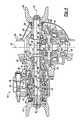
- FIG. 4is a cross-section top view of a carrier assembly for a forward drive axle in a tandem axle set incorporating the subject invention.
- FIG. 5is a schematic front view of the carrier assembly of FIG. 4 incorporated into the forward drive axle.
- a powertrain assemblyis shown generally at 10 in FIG. 1 .
- the powertrain assembly 10includes an engine 12 and transmission 14 that drive a driveshaft 16 as is known in the art.
- the driveshaft 16is coupled to a forward drive axle 18 of a tandem axle set at an input 20 .
- the forward drive axle 18includes a carrier 22 , axle housing 24 , and a pair of laterally spaced wheel ends 26 positioned on opposing ends of the axle housing 24 .
- the carrier 22includes a carrier housing 28 and differential assembly 30 that is operably coupled to drive a pair of axle shafts 32 .
- the axle shafts 32drive the wheel ends 26 , which support tires 34 as is known in the art.
- the tandem axle setalso includes a rear drive axle 36 that is coupled to the forward drive axle 18 with a connecting driveshaft 38 .
- An inter-axle differential (IAD) 40located in the forward carrier 22 , splits driving power supplied at the input 20 between the forward 18 and rear 36 drive axles.
- the IAD 40drives the differential assembly 30 in the forward drive axle 18 and transfers driving power to the connecting driveshaft 28 for the rear drive axle 26 via a thru-shaft 42 .
- the connecting driveshaft 38is coupled to the rear drive axle 26 at input 44 .
- the rear drive axle 36includes a carrier 46 , axle housing 48 , and a pair of laterally spaced wheel ends 50 positioned on opposing ends of the axle housing 48 .
- the carrier 46includes a carrier housing 52 and differential assembly 54 that is operably coupled to drive a pair of axle shafts 56 .
- the axle shafts 56drive the wheel ends 50 , which support tires 58 as discussed above.
- a traditional carrier assembly 60 for a forward drive axle 18 in a tandem setis shown in FIG. 2 .
- the carrier assembly 60includes an input 62 to an inter-axle differential assembly (IAD) 64 that splits the driving input between a gearset 66 in the forward drive axle 18 and a thru-shaft 68 that transfers driving power to the rear drive axle 36 .
- the gearset 66is a helical gearset that transfers the driving power from the input 62 down to a gear assembly including a pinion gear 70 and ring gear 72 .
- the pinion 70 and ring 72 gearsdrive a differential assembly 74 (shown in FIG. 3 ), which in turn drives the axle shafts 32 .
- the operation of the helical gearset in combination with the ring 72 and pinion 70 gearsis well known and will not be discussed in detail.
- the thru-shaft 68defines a thru-shaft axis of rotation 76 that is vertically higher than a pinion gear axis of rotation 78 .
- the axle shafts 32define an axle shaft axis of rotation 80 that is transverse to the thru-shaft 76 and pinion gear 78 axes of rotation.
- the pinion gear axis of rotation 78is vertically lower than the axle shaft axis of rotation 80 and the thru-shaft axis of rotation 76 is vertically higher than the axle shaft axis of rotation 80 .
- the helical gear configurationis required to permit the thru-shaft 68 to pass the differential assembly 74 . This configuration severely limits the overall size of the differential because sufficient clearance is required to allow the thru-shaft 68 to operate.
- the pinion gear 70includes a plurality of pinion teeth 82 that mesh with a plurality of ring gear teeth 84 formed on the ring gear 72 .
- the ring gear 72includes a front face 86 on which the ring gear teeth 84 are formed and a back face 88 .
- the pinion gear 70drives the ring gear 72 , which is operably coupled, to the differential assembly 74 .
- the differential assembly 74includes a first differential case half 90 , a second differential case half 92 , and a differential gear assembly 94 .
- the first 90 and second 92 differential case halvessupport the differential gear assembly 94 .
- the differential gear assembly 94includes four (4) differential pinion gears 96 (only two are shown), supported on a four-legged differential spider 98 as is known in the art.
- the differential pinion gears 96intermesh with a pair of side gears 100 that are splined to the axle shafts 32 .
- the operation of the differential assembly 74is well known and will not be discussed in detail.
- the ring gear 72is attached to the second differential case half 92 at a first bolted joint 102 with a plurality of fasteners 104 .
- the first 90 and second 92 differential case halvesare attached to each other, defining a differential case split line 106 , at a second bolted joint 108 with a plurality of fasteners 110 .
- the differential case split line 106is positioned on the front side 86 of the ring gear 72 .
- the differential case halves 90 , 92are supported by a pair of bearings 112 having a traditional mounting configuration with bearing apexes extending toward each other.
- the pinion gear 70includes a pinion gear head 114 supported on a shaft portion 116 that extends through the center of one of the helical gears 66 a .
- a pair of pinion bearings 118support the pinion gear 70 for rotation relative to a carrier housing 120 .
- the pinion bearings 118are mounted outwardly of from pinion gear head 114 and are located on opposing sides of the helical gear 66 a.
- This traditional carrier assembly 60 configuration for a forward drive axle 18is expensive to manufacture and difficult to assemble. Also, with the increased demand for more robust component designs within the same packaging space, these traditional configurations do not provide room to make critical components more robust within the existing package.
- the subject invention as shown in FIG. 4provides an improved carrier configuration for a forward drive axle 18 that significantly reduces the number of components, is easy to assemble, and provides more robust components than traditional configurations.
- the carrier assembly 130includes an input 132 coupled to an inter-axle differential assembly (IAD) 134 that splits driving input between the forward drive axle 18 and the rear drive axle 36 .
- the IAD 134transfers driving input to an output 136 for the forward drive axle via a thru-shaft 138 .
- IADinter-axle differential assembly
- the IAD 134includes a includes differential spider 140 , a plurality of spider gears 142 supported on the differential spider 140 , an inner side gear 144 in meshing engagement with the spider gears 142 , and an outer side gear 146 in meshing engagement with the spider gears 142 .
- the differential spider 140 , spider gears 142 , and inner 144 and outer 146 side gearsare substantially enclosed within an IAD housing 148 .
- the housing 148is rotatably supported on an IAD bearing assembly 150 .
- the IAD bearing assemblyis a single tapered roller bearing.
- the IAD 134drives a pinion gear 152 that is in meshing engagement with a ring gear 154 that is operably coupled to a differential 156 for the forward drive axle 18 .
- the pinion gear 152is a two-piece design with a first piece 158 that defines a pinion gear head 160 with a plurality of pinion gear teeth 162 .
- the first piece 158includes a hollow sleeve portion 164 that extends outwardly from the pinion gear head 160 toward the IAD 134 .
- the pinion gear 152includes a second piece 166 that defines a hollow pinion support shaft 168 having an inner end 170 , an outer end 172 , and center flange portion 174 .
- the two pieces 158 , 166are preferably fastened together with at least one fastening component 176 , however, other known connection components could also be used.
- the fastening component 176is a nut threaded onto the second piece 166 .
- the second piece 168extends through the hollow sleeve portion 164 with the inner end 170 extending inwardly beyond the pinion gear head 160 .
- the outer end 172extends into the IAD 134 to apply a thrust load to the IAD bearing assembly 150 to permit reverse load sharing.
- the thru-shaft 138extends through the hollow pinion support shaft 168 such that the thru-shaft 138 and pinion gear 152 rotate about a common axis 178 .
- a distal end 180 of the hollow sleeve portion 164abuts against the center flange portion 174 to properly locate the first 158 and second pieces relative to one another.
- an outer end 182 of the thru-shaft 138is fixed for rotation with the outer side gear 146 of the IAD 134 and the second piece 166 of the pinion gear 152 is fixed for rotation with the inner side gear 144 .
- the inner side gear 144is splined to an outer surface of the second piece 166 at a center position adjacent to the central flange portion 174 .
- the thru-shaft 138extends through the second piece 166 such that independent rotation between thru-shaft 138 and the second piece 166 is permitted.
- the carrier assembly 130optionally includes a differential locking assembly, shown generally at 184 , to selectively lock the inner side gear 144 , pinion gear 152 , and thru-shaft 138 together for rotation at the same speed.
- the pinion gear 152is rotatably supported by an inner bearing 186 and an outer bearing 188 .
- the inner 186 and outer 188 bearingsare positioned on opposing sides of the pinion gear head 160 .
- the inner bearing 186is supported between the second piece 166 and a carrier housing member 190 and the outer bearing 188 is supported between the first piece 158 and the carrier housing member 190 .
- the outer bearing 188abuts against the center flange portion 174 of the second piece 166 .
- the inner and outer bearings 186 , 188are single tapered roller bearings. Due to the raising of the pinion position about axle centerline, discussed in greater detail below, the outer bearing 188 is larger in size than the inner bearing 186 .
- a bearing preload spacer 192is positioned between the pinion gear head 160 and the inner bearing 186 .
- the fastening component 176abuts against the inner bearing 186 and can be adjusted to apply the desired preload bearing force.
- the outer end of the second piece 166 of the pinion gear 152abuts against the outer side gear 146 to apply the thrust load to the IAD bearing assembly 150 .
- Thisallows the IAD bearing assembly 150 to share reverse loading, which in turn allows the inner bearing 186 to be small enough to clear the ring gear 154 .
- the differential assembly 156includes a first differential case half 194 , a second differential case half 196 , and a differential gear assembly.
- the first 194 and second 196 differential case halvessupport the differential gear assembly.
- the differential gear assemblyincludes four (4) differential pinion gears 198 (only two are shown), supported on a four-legged differential spider 200 as is known in the art.
- the differential pinion gears 198intermesh with a pair of side gears 202 that are splined to the axle shafts 32 .
- the ring gear 154includes a back face 204 and a front face 206 on which a plurality of ring gear teeth 208 are formed.
- the pinion gear teeth 162intermesh with the ring gear teeth 208 to drive the differential assembly 156 .
- the first 194 and second 196 differential case halvesare attached to each other, defining a differential case split line 210 that is positioned on the back face 204 of the ring gear 154 .
- the ring gear 154 , first differential case half 194 , and second differential case half 196are all connected together at a single bolted joint 212 with a plurality of fasteners 214 .
- differential assembly configurationOne benefit with this differential assembly configuration is that larger differential components can be used within the packing space defined by a traditional configuration.
- the differential case diameteris not restricted by the proximity of the pinion gear, as in traditional configurations.
- the size of the differential case components and gearingcan be enlarged to increase robustness.
- the differential assembly 156is rotatably supported within the carrier assembly 130 by at least one tapered roller bearing 216 .
- the improved differential case configurationpermits the bearing 216 to be mounted in a reverse configuration.
- the bearing 216includes a plurality of rollers 218 defining bearing apexes that diverge away from one another in a direction extending outwardly from the back face 204 of the ring gear 154 . This reverse bearing configuration provides more stability and reduces the need for thrust screws.
- the thru-shaft 138has a first end 182 fixed to the outer side gear 146 of the IAD 134 and a second end 220 coupled to the output 136 .
- the second end 220 of the thru-shaft 138is preferably supported by a single tapered roller bearing 222 .
- the tapered roller bearing 222is positioned between the thru-shaft 138 and the carrier housing member 190 .
- the carrier housing member 190is fastened to an axle housing member 224 as is known in the art.
- the carrier mounting castingis extend to the bowl side of the carrier assembly 130 and includes a projection 226 that locates into the housing 224 .
- the projection 226supports the bearing 222 and eliminates the need for a separate bearing cage member in the housing 224 . This configuration also provides improved alignment of the thru-shaft 138 in the carrier assembly 130 .
- the input at the pinion gear 152defines a pinion centerline 228 , shown in FIG. 5, which is vertically higher than an axle centerline 230 defined by the axle shafts 32 .
- the drive loadpulls on the pinion gear 152 rather than pushing on the pinion gear 152 as is done in traditional configurations.
- the use of a two-piece pinion gear 152 that abuts against the outer side gear 146 of the IAD 134permits reverse load sharing with the IAD bearing assembly 150 . Further, this configuration permits the inner pinion bearing assembly size to be decreased.
- the subject inventionprovides an improved carrier assembly for a forward drive axle of a tandem set that includes a more robust component configuration within a traditional package.
- This carrier configurationfurther reduces the overall number of required components and is less expensive to manufacture.
Landscapes
- Engineering & Computer Science (AREA)
- Mechanical Engineering (AREA)
- Chemical & Material Sciences (AREA)
- Combustion & Propulsion (AREA)
- Transportation (AREA)
- General Engineering & Computer Science (AREA)
- Retarders (AREA)
- General Details Of Gearings (AREA)
- Rolling Contact Bearings (AREA)
- Arrangement And Driving Of Transmission Devices (AREA)
Abstract
Description
Claims (25)
Priority Applications (2)
| Application Number | Priority Date | Filing Date | Title |
|---|---|---|---|
| US10/127,584US6648788B1 (en) | 2002-04-26 | 2002-04-26 | Forward carrier assembly for tandem axle |
| JP2003112318AJP2004001726A (en) | 2002-04-26 | 2003-04-17 | Front wheel carrier assembly for tandem axle |
Applications Claiming Priority (1)
| Application Number | Priority Date | Filing Date | Title |
|---|---|---|---|
| US10/127,584US6648788B1 (en) | 2002-04-26 | 2002-04-26 | Forward carrier assembly for tandem axle |
Publications (2)
| Publication Number | Publication Date |
|---|---|
| US20030203783A1 US20030203783A1 (en) | 2003-10-30 |
| US6648788B1true US6648788B1 (en) | 2003-11-18 |
Family
ID=29248434
Family Applications (1)
| Application Number | Title | Priority Date | Filing Date |
|---|---|---|---|
| US10/127,584Expired - LifetimeUS6648788B1 (en) | 2002-04-26 | 2002-04-26 | Forward carrier assembly for tandem axle |
Country Status (2)
| Country | Link |
|---|---|
| US (1) | US6648788B1 (en) |
| JP (1) | JP2004001726A (en) |
Cited By (18)
| Publication number | Priority date | Publication date | Assignee | Title |
|---|---|---|---|---|
| US20040079562A1 (en)* | 2002-10-23 | 2004-04-29 | Oates Jack Darrin | Inter-axle differential assembly for a tandem drive axle set |
| US20040087408A1 (en)* | 2002-11-06 | 2004-05-06 | James Ziech | Concentric shift system for engaging an interaxle differential lock |
| US20040096460A1 (en)* | 1998-08-24 | 2004-05-20 | Pfizer Inc | Compositions and methods for protecting animals from lentivirus-associated disease such as feline immunodeficiency virus |
| US20040204282A1 (en)* | 2002-11-06 | 2004-10-14 | Michael Green | Inter-axle differential lock shift mechanism |
| US20050101430A1 (en)* | 2003-11-06 | 2005-05-12 | Ziech James F. | Drive system and method of assembly thereof |
| US20050247148A1 (en)* | 2004-05-10 | 2005-11-10 | Steve Slesinski | Output yoke shaft and assembly |
| US20070004262A1 (en)* | 2004-02-24 | 2007-01-04 | Renault Trucks | Mechanical adapter assembly |
| DE102008015227A1 (en) | 2008-03-20 | 2009-03-19 | Daimler Ag | Drive train for motor vehicle i.e. commercial motor vehicle, has clutch mechanism aiding half shafts, where clutch mechanism is coupleable and decoupleable from drive shaft and formed as differential gear with unequal torque distribution |
| US20090084223A1 (en)* | 2006-01-27 | 2009-04-02 | Clive James Harrup | Differential gear casing and method |
| US20110136611A1 (en)* | 2009-12-07 | 2011-06-09 | Martin Iii Robert J | Differential lock with assisted return |
| US8851212B2 (en) | 2011-08-31 | 2014-10-07 | Mack Trucks, Inc. | Forward carrier assembly with a reversible inter-axle differential for a tandem axle vehicle, a powertrain for a tandem axle vehicle, and a tandem axle vehicle |
| US9022893B2 (en) | 2010-07-22 | 2015-05-05 | Arvinmeritor Technology, Llc | Hypoid gear set for drive axle |
| US9457654B2 (en) | 2015-01-20 | 2016-10-04 | Arvinmeritor Technology, Llc | Drive axle system |
| US10011174B2 (en) | 2016-11-04 | 2018-07-03 | Dana Heavy Vehicle Systems Group, Llc | Tandem axle gearing arrangement |
| EP3372434A1 (en) | 2017-03-10 | 2018-09-12 | ArvinMeritor Technology, LLC | Axle assembly having a drive pinion support bearing and a method of assembly |
| US10315515B2 (en)* | 2016-08-05 | 2019-06-11 | Honda Motor Co., Ltd. | Power transfer unit pinion shaft and propeller shaft coupling member for a vehicle, and methods of use and manufacture thereof |
| US20230072312A1 (en)* | 2021-09-08 | 2023-03-09 | Joseph Ghattas | System and method to add an additional drive axle to a vehicle |
| US11808342B2 (en) | 2022-02-08 | 2023-11-07 | Dana Automotive Systems Group, Llc | Differential carrier |
Families Citing this family (9)
| Publication number | Priority date | Publication date | Assignee | Title |
|---|---|---|---|---|
| US20070117672A1 (en)* | 2005-11-18 | 2007-05-24 | Elvins Francis J | Tandem axle system |
| CN101905651A (en)* | 2009-06-07 | 2010-12-08 | 周殿玺 | Differential-twist driving device |
| CN104175892A (en)* | 2013-05-23 | 2014-12-03 | 陕西汉德车桥有限公司 | Commercial vehicle main speed reducer assembly and single-stage speed-reducing driving axle |
| CN104626978B (en)* | 2015-03-12 | 2017-03-01 | 济南大学 | Vehicle active-type differential gearing vehicle bridge |
| US10539218B2 (en)* | 2017-08-23 | 2020-01-21 | Arvinmeritor Technology, Llc | Axle assembly having a drive pinion assembly |
| US10703202B2 (en)* | 2018-02-12 | 2020-07-07 | Arvinmeritor Technology, Llc | Drive axle assembly with clutch collar |
| EP3790770A1 (en)* | 2018-05-10 | 2021-03-17 | ArvinMeritor Technology, LLC | Axle assembly having an electric motor module and a terminal box |
| CN116398603A (en)* | 2023-03-01 | 2023-07-07 | 陕西汉德车桥有限公司 | A lightweight through-type main reducer assembly |
| CN116653587B (en)* | 2023-05-19 | 2025-09-23 | 一汽解放汽车有限公司 | Drive axle capable of drive conversion and vehicle |
Citations (8)
| Publication number | Priority date | Publication date | Assignee | Title |
|---|---|---|---|---|
| US2693244A (en)* | 1950-06-15 | 1954-11-02 | Rockwell Spring & Axle Co | Multiwheeler with angle drive |
| US2699075A (en)* | 1951-08-16 | 1955-01-11 | Rockwell Spring & Axle Co | Vehicle drive mechanism |
| USRE25269E (en) | 1962-10-23 | Axle mechanism | ||
| US3532183A (en)* | 1968-02-26 | 1970-10-06 | Clark Equipment Co | Lubrication system for a differential |
| US3887037A (en)* | 1974-03-20 | 1975-06-03 | Clark Equipment Co | Lubrication system for differentials |
| US4050534A (en) | 1975-02-13 | 1977-09-27 | Eaton Corporation | Drive axle system useable in 6 × 6 vehicle |
| US5860889A (en) | 1995-12-01 | 1999-01-19 | Dana Corporation | Tandem forward rear axle lockout |
| US6200240B1 (en)* | 1999-02-11 | 2001-03-13 | Meritor Heavy Vehicle Systems, Llc | Inter-axle differential assembly for a tandem drive axle set |
- 2002
- 2002-04-26USUS10/127,584patent/US6648788B1/ennot_activeExpired - Lifetime
- 2003
- 2003-04-17JPJP2003112318Apatent/JP2004001726A/enactivePending
Patent Citations (8)
| Publication number | Priority date | Publication date | Assignee | Title |
|---|---|---|---|---|
| USRE25269E (en) | 1962-10-23 | Axle mechanism | ||
| US2693244A (en)* | 1950-06-15 | 1954-11-02 | Rockwell Spring & Axle Co | Multiwheeler with angle drive |
| US2699075A (en)* | 1951-08-16 | 1955-01-11 | Rockwell Spring & Axle Co | Vehicle drive mechanism |
| US3532183A (en)* | 1968-02-26 | 1970-10-06 | Clark Equipment Co | Lubrication system for a differential |
| US3887037A (en)* | 1974-03-20 | 1975-06-03 | Clark Equipment Co | Lubrication system for differentials |
| US4050534A (en) | 1975-02-13 | 1977-09-27 | Eaton Corporation | Drive axle system useable in 6 × 6 vehicle |
| US5860889A (en) | 1995-12-01 | 1999-01-19 | Dana Corporation | Tandem forward rear axle lockout |
| US6200240B1 (en)* | 1999-02-11 | 2001-03-13 | Meritor Heavy Vehicle Systems, Llc | Inter-axle differential assembly for a tandem drive axle set |
Non-Patent Citations (2)
| Title |
|---|
| A.F. Andreev, V. V. Vantesevich, A. Kh. Lefarov: "Interwheel Differential Drive; Differential s of Wheeled Vehicles", Moscow Mashinostroyenie, 1987, pp. 35-45. |
| Translation of above-noted Russian reference. |
Cited By (27)
| Publication number | Priority date | Publication date | Assignee | Title |
|---|---|---|---|---|
| US20040096460A1 (en)* | 1998-08-24 | 2004-05-20 | Pfizer Inc | Compositions and methods for protecting animals from lentivirus-associated disease such as feline immunodeficiency virus |
| US6840882B2 (en)* | 2002-10-23 | 2005-01-11 | Arvinmeritor Technology, Llc | Inter-axle differential assembly for a tandem drive axle set |
| US20040079562A1 (en)* | 2002-10-23 | 2004-04-29 | Oates Jack Darrin | Inter-axle differential assembly for a tandem drive axle set |
| US6918851B2 (en)* | 2002-11-06 | 2005-07-19 | Dana Corporation | Concentric shift system for engaging an interaxle differential lock |
| US20040204282A1 (en)* | 2002-11-06 | 2004-10-14 | Michael Green | Inter-axle differential lock shift mechanism |
| US7211017B2 (en) | 2002-11-06 | 2007-05-01 | Dana Corporation | Inter-axle differential lock shift mechanism |
| US20040087408A1 (en)* | 2002-11-06 | 2004-05-06 | James Ziech | Concentric shift system for engaging an interaxle differential lock |
| US20050101430A1 (en)* | 2003-11-06 | 2005-05-12 | Ziech James F. | Drive system and method of assembly thereof |
| US7500934B2 (en) | 2003-11-06 | 2009-03-10 | Dana Heavy Vehicle Systems Group, Llc | Drive system and method of assembly thereof |
| US7686728B2 (en)* | 2004-02-24 | 2010-03-30 | Renault Trucks | Mechanical adapter assembly |
| US20070004262A1 (en)* | 2004-02-24 | 2007-01-04 | Renault Trucks | Mechanical adapter assembly |
| US20050247148A1 (en)* | 2004-05-10 | 2005-11-10 | Steve Slesinski | Output yoke shaft and assembly |
| US7690449B2 (en)* | 2004-05-10 | 2010-04-06 | Dana Heavy Vehicle Systems Group, Llc | Output yoke shaft and assembly |
| US20090084223A1 (en)* | 2006-01-27 | 2009-04-02 | Clive James Harrup | Differential gear casing and method |
| US8327541B2 (en) | 2006-01-27 | 2012-12-11 | Meritor Heavy Vehicle Systems Cameri Spa | Method of assembling a differential mechanism |
| DE102008015227A1 (en) | 2008-03-20 | 2009-03-19 | Daimler Ag | Drive train for motor vehicle i.e. commercial motor vehicle, has clutch mechanism aiding half shafts, where clutch mechanism is coupleable and decoupleable from drive shaft and formed as differential gear with unequal torque distribution |
| US20110136611A1 (en)* | 2009-12-07 | 2011-06-09 | Martin Iii Robert J | Differential lock with assisted return |
| US9453570B2 (en) | 2009-12-07 | 2016-09-27 | Arvinmeritor Technology, Llc | Differential lock with assisted return |
| US9022893B2 (en) | 2010-07-22 | 2015-05-05 | Arvinmeritor Technology, Llc | Hypoid gear set for drive axle |
| US8851212B2 (en) | 2011-08-31 | 2014-10-07 | Mack Trucks, Inc. | Forward carrier assembly with a reversible inter-axle differential for a tandem axle vehicle, a powertrain for a tandem axle vehicle, and a tandem axle vehicle |
| US9457654B2 (en) | 2015-01-20 | 2016-10-04 | Arvinmeritor Technology, Llc | Drive axle system |
| US10315515B2 (en)* | 2016-08-05 | 2019-06-11 | Honda Motor Co., Ltd. | Power transfer unit pinion shaft and propeller shaft coupling member for a vehicle, and methods of use and manufacture thereof |
| US10011174B2 (en) | 2016-11-04 | 2018-07-03 | Dana Heavy Vehicle Systems Group, Llc | Tandem axle gearing arrangement |
| EP3372434A1 (en) | 2017-03-10 | 2018-09-12 | ArvinMeritor Technology, LLC | Axle assembly having a drive pinion support bearing and a method of assembly |
| US10208846B2 (en) | 2017-03-10 | 2019-02-19 | Arvinmeritor Technology, Llc | Axle assembly having a drive pinion support bearing and a method of assembly |
| US20230072312A1 (en)* | 2021-09-08 | 2023-03-09 | Joseph Ghattas | System and method to add an additional drive axle to a vehicle |
| US11808342B2 (en) | 2022-02-08 | 2023-11-07 | Dana Automotive Systems Group, Llc | Differential carrier |
Also Published As
| Publication number | Publication date |
|---|---|
| JP2004001726A (en) | 2004-01-08 |
| US20030203783A1 (en) | 2003-10-30 |
Similar Documents
| Publication | Publication Date | Title |
|---|---|---|
| US6648788B1 (en) | Forward carrier assembly for tandem axle | |
| US6705965B2 (en) | Carrier assembly for drive axle | |
| US6886655B2 (en) | Vehicle wheel end assembly with double reduction gear set | |
| US7350606B2 (en) | Double reduction electric drive wheel assembly | |
| US7291083B2 (en) | Inter-axle differential assembly | |
| EP1352771A2 (en) | Tandem axle power divider assembly with inboard slip driveshaft connection | |
| US6840882B2 (en) | Inter-axle differential assembly for a tandem drive axle set | |
| EP1481835A1 (en) | Forward carrier assembly for tandem axle | |
| US7258644B2 (en) | Tandem axle carrier structural rib | |
| US6755093B2 (en) | Planetary drive assembly with idlers for low floor vehicle | |
| US6676228B1 (en) | Vehicle wheel end assembly with support tube | |
| US6689009B1 (en) | Compact differential assembly | |
| US5117937A (en) | Transfer device for four wheel drive motor vehicle | |
| US6957710B2 (en) | Tandem drive axle assembly | |
| US6949046B2 (en) | Gear to case assembly for drive axle | |
| CN215435997U (en) | Drive axle assembly of vehicle and vehicle | |
| US3768821A (en) | Split torque drivetrain for multiple wheel vehicle | |
| US10941846B2 (en) | Differential assembly having an overhanging ring gear | |
| US7318785B2 (en) | Worm gear differential | |
| CN113623377B (en) | Internal limiting double-anti-drop interaxial differential mechanism structure assembly | |
| US20030155170A1 (en) | Drive assembly for low floor vehicle | |
| JP3931369B2 (en) | Power transmission device for four-wheel drive vehicles | |
| JP3059808B2 (en) | Tractor front wheel drive mechanism | |
| JPS6227733Y2 (en) | ||
| JPH0692153A (en) | Driving power transmitting device for vehicle |
Legal Events
| Date | Code | Title | Description |
|---|---|---|---|
| AS | Assignment | Owner name:MERITOR HEAVY VEHICLE TECHNOLOGY, LLC, MICHIGAN Free format text:ASSIGNMENT OF ASSIGNORS INTEREST;ASSIGNOR:SULLIVAN, WILLIAM C.;REEL/FRAME:012846/0005 Effective date:20020420 | |
| STCF | Information on status: patent grant | Free format text:PATENTED CASE | |
| AS | Assignment | Owner name:ARVINMERITOR TECHNOLOGY, LLC, MICHIGAN Free format text:CHANGE OF NAME;ASSIGNOR:MERITOR HEAVY VEHICLE TECHNOLOGY, LLC;REEL/FRAME:018362/0749 Effective date:20011221 | |
| AS | Assignment | Owner name:JPMORGAN CHASE BANK, NATIONAL ASSOCIATION, FOR ITS Free format text:SECURITY AGREEMENT;ASSIGNOR:ARVINMERITOR TECHNOLOGY, LLC;REEL/FRAME:018524/0669 Effective date:20060823 | |
| FPAY | Fee payment | Year of fee payment:4 | |
| SULP | Surcharge for late payment | ||
| FPAY | Fee payment | Year of fee payment:8 | |
| FPAY | Fee payment | Year of fee payment:12 | |
| AS | Assignment | Owner name:AXLETECH INTERNATIONAL IP HOLDINGS, LLC, MICHIGAN Free format text:RELEASE BY SECURED PARTY;ASSIGNOR:JPMORGAN CHASE BANK, N.A., AS ADMINISTRATIVE AGENT;REEL/FRAME:061521/0550 Effective date:20220803 Owner name:MERITOR TECHNOLOGY, LLC, MICHIGAN Free format text:RELEASE BY SECURED PARTY;ASSIGNOR:JPMORGAN CHASE BANK, N.A., AS ADMINISTRATIVE AGENT;REEL/FRAME:061521/0550 Effective date:20220803 Owner name:MOTOR HEAVY VEHICLE SYSTEMS, LLC, MICHIGAN Free format text:RELEASE BY SECURED PARTY;ASSIGNOR:JPMORGAN CHASE BANK, N.A., AS ADMINISTRATIVE AGENT;REEL/FRAME:061521/0550 Effective date:20220803 Owner name:ARVINMERITOR OE, LLC, MICHIGAN Free format text:RELEASE BY SECURED PARTY;ASSIGNOR:JPMORGAN CHASE BANK, N.A., AS ADMINISTRATIVE AGENT;REEL/FRAME:061521/0550 Effective date:20220803 Owner name:MERITOR HEAVY VEHICLE SYSTEMS, LLC, MICHIGAN Free format text:RELEASE BY SECURED PARTY;ASSIGNOR:JPMORGAN CHASE BANK, N.A., AS ADMINISTRATIVE AGENT;REEL/FRAME:061521/0550 Effective date:20220803 Owner name:ARVINMERITOR TECHNOLOGY, LLC, MICHIGAN Free format text:RELEASE BY SECURED PARTY;ASSIGNOR:JPMORGAN CHASE BANK, N.A., AS ADMINISTRATIVE AGENT;REEL/FRAME:061521/0550 Effective date:20220803 Owner name:MAREMOUNT CORPORATION, MICHIGAN Free format text:RELEASE BY SECURED PARTY;ASSIGNOR:JPMORGAN CHASE BANK, N.A., AS ADMINISTRATIVE AGENT;REEL/FRAME:061521/0550 Effective date:20220803 Owner name:EUCLID INDUSTRIES, LLC, MICHIGAN Free format text:RELEASE BY SECURED PARTY;ASSIGNOR:JPMORGAN CHASE BANK, N.A., AS ADMINISTRATIVE AGENT;REEL/FRAME:061521/0550 Effective date:20220803 Owner name:GABRIEL RIDE CONTROL PRODUCTS, INC., MICHIGAN Free format text:RELEASE BY SECURED PARTY;ASSIGNOR:JPMORGAN CHASE BANK, N.A., AS ADMINISTRATIVE AGENT;REEL/FRAME:061521/0550 Effective date:20220803 Owner name:ARVIN TECHNOLOGIES, INC., MICHIGAN Free format text:RELEASE BY SECURED PARTY;ASSIGNOR:JPMORGAN CHASE BANK, N.A., AS ADMINISTRATIVE AGENT;REEL/FRAME:061521/0550 Effective date:20220803 Owner name:MERITOR TRANSMISSION CORPORATION, MICHIGAN Free format text:RELEASE BY SECURED PARTY;ASSIGNOR:JPMORGAN CHASE BANK, N.A., AS ADMINISTRATIVE AGENT;REEL/FRAME:061521/0550 Effective date:20220803 Owner name:ARVINMERITOR, INC., MICHIGAN Free format text:RELEASE BY SECURED PARTY;ASSIGNOR:JPMORGAN CHASE BANK, N.A., AS ADMINISTRATIVE AGENT;REEL/FRAME:061521/0550 Effective date:20220803 |