US6648484B1 - Case for encapsulating mirror element - Google Patents
Case for encapsulating mirror elementDownload PDFInfo
- Publication number
- US6648484B1 US6648484B1US09/931,990US93199001AUS6648484B1US 6648484 B1US6648484 B1US 6648484B1US 93199001 AUS93199001 AUS 93199001AUS 6648484 B1US6648484 B1US 6648484B1
- Authority
- US
- United States
- Prior art keywords
- case
- mirror element
- side wall
- mirror
- lip
- Prior art date
- Legal status (The legal status is an assumption and is not a legal conclusion. Google has not performed a legal analysis and makes no representation as to the accuracy of the status listed.)
- Expired - Lifetime, expires
Links
- 230000002093peripheral effectEffects0.000claimsdescription14
- 239000004743PolypropyleneSubstances0.000claimsdescription5
- -1polypropylenePolymers0.000claimsdescription5
- 229920001155polypropylenePolymers0.000claimsdescription5
- 229920005570flexible polymerPolymers0.000claimsdescription2
- 230000000712assemblyEffects0.000description2
- 238000000429assemblyMethods0.000description2
- 230000006835compressionEffects0.000description2
- 238000007906compressionMethods0.000description2
- 241000894006BacteriaSpecies0.000description1
- 241000233866FungiSpecies0.000description1
- 238000005299abrasionMethods0.000description1
- 238000010521absorption reactionMethods0.000description1
- 239000002253acidSubstances0.000description1
- 150000007513acidsChemical class0.000description1
- 239000003963antioxidant agentSubstances0.000description1
- 239000011521glassSubstances0.000description1
- 239000003292glueSubstances0.000description1
- 238000000465mouldingMethods0.000description1
- 230000003647oxidationEffects0.000description1
- 238000007254oxidation reactionMethods0.000description1
- XLYOFNOQVPJJNP-UHFFFAOYSA-NwaterSubstancesOXLYOFNOQVPJJNP-UHFFFAOYSA-N0.000description1
Images


Classifications
- B—PERFORMING OPERATIONS; TRANSPORTING
- B60—VEHICLES IN GENERAL
- B60R—VEHICLES, VEHICLE FITTINGS, OR VEHICLE PARTS, NOT OTHERWISE PROVIDED FOR
- B60R1/00—Optical viewing arrangements; Real-time viewing arrangements for drivers or passengers using optical image capturing systems, e.g. cameras or video systems specially adapted for use in or on vehicles
- B60R1/02—Rear-view mirror arrangements
Definitions
- This inventionrelates in general to mirror assemblies for motor vehicles and, in particular, to a case for encapsulating a mirror element. Most particularly, the invention relates to a biasing element for biasing a mirror element towards a lip of a case while pulling the lip towards the mirror.
- Mirror assembliesare generally comprised of a case and a mirror element, typically a transparent glass, prismatic element. Mirror elements are generally attached to the surface of the case with glue or double-stick tape. Alternatively, cases encapsulate mirror elements. Such cases include a lip defining an opening. The opening is smaller than the mirror element but the lip is flexible to permit the opening to receive the mirror element. Tension tabs are provided in the case to act against the mirror to reduce vibration of the mirror element. An undesirable gap remains present between the mirror element and the lip of the case.
- a mirror assemblyis needed that further reduces the risk that the mirror element will vibrate and that reduces the risk of a gap being present between the mirror element and the lip of the case.
- the present inventionis directed towards a case for encapsulating a mirror element.
- the casereduces the risk of the mirror element vibrating and reduces the risk of a gap being present between the mirror element and the lip of the case.
- the casecomprises a back wall.
- a side wallis integral with the back wall.
- a lipextends from the side wall.
- the lipdefines an opening that is adapted to receive the mirror element.
- a biasing elementis adapted to act upon the mirror element when the mirror element is encapsulated in the case to apply a force against the mirror element in a first direction.
- the biasing elementis coupled to the side wall of the case to pull the side wall in a second direction so as to pull the lip against the mirror element.
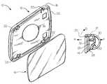
- FIG. 1is an exploded perspective view of a mirror assembly comprising a case and a mirror element encapsulated in the case.
- FIG. 2is a diagrammatic representation of a biasing element that acts upon the mirror element when the mirror element is encapsulated in the case.
- FIG. 3is an enlarged rear elevational view of the case shown in FIG. 1 .
- FIG. 4is an enlarged partial sectional view of a mirror element between the lip of the case by a biasing element in the form of a tab placed in tension.
- FIG. 5is an enlarged elevational view of a portion of the case shown in FIGS. 1 and 3 with holes therein defining a tab.
- FIG. 6is an enlarged partial sectional view of a tab placed in tension and a tie-in element pulling the peripheral wall of the case, which in turn pulls the lip of the case against the mirror element.
- FIG. 7is an enlarged partial sectional view of a heater attached to a mirror element and double-stick tape adhered between the heater and the back wall of the case.
- FIG. 1a mirror assembly 10 that is adapted for use with a motor vehicle.
- the assembly 10comprises a case 12 and a mirror element 14 encapsulated in the case 12 .
- the case 12is held by a mirror shell or body, which is not shown.
- the case 12is preferably molded from a flexible polymer, such as synthetic polypropylene.
- Polypropylenehas a low water absorption property and is substantially impermeable to moisture. It is not attacked by fungi or bacteria and it resists acids and alkalis. It has a fair resistance to abrasions and a good heat resistance. Moreover, it has a high-impact strength and maintains its strength after flexing.
- Polypropylenemay be readily colored and protected against oxidation by antioxidants. Hence, polypropylene is suitable for molding a mirror assembly that is adapted for use with motor vehicles.
- the case 12is preferably a molded hollow structure having a back wall 16 and a continuous peripheral side wall 18 integral with the back wall 16 .
- a rim or lip 20extends around the rearward edge of the peripheral side wall 18 .
- the lip 20is spaced from the back wall 16 , forming a channel between the back wall 16 and the lip 20 .
- the lip 20defines an opening that is adapted to receive the mirror element 14 .
- the openingis normally positioned to face rearward of the motor vehicle when held by the mirror body.
- a biasing elementacts upon the mirror element 14 when the mirror element 14 is encapsulated in the case 12 .
- the biasing elementis held in tension or compression when the mirror element 14 is encapsulated in the case 12 to apply a force against the mirror element 14 in the direction of arrow R (shown in FIG. 4 ), rearward of the motor vehicle.
- the biasing elementis coupled to the peripheral side wall 18 so that it may act upon the peripheral side wall 18 to pull the peripheral side wall 18 forward, in the direction of arrow F (also shown in FIG. 4 ). This is diagrammatically represented in FIG. 2 .
- the biasing elementmay be in the form of a tab 22 .
- the tab 22may be supported by the back wall 16 of the case 12 .
- the tab 22may be formed in any suitable manner.
- the tab 22is integral with the back wall 16 .
- the periphery of the tab 22may be defined by holes 24 a , 24 b in the back wall 16 .
- the tab 22may be defined by a body 26 having opposing ends 28 , 30 .
- a first end 28is integrally connected to the back wall 16 .
- a second end 30is adapted to move freely relative to the first end 28 .
- the free end 30 of the body 26may be provided with a protrusion or bump 32 that extends rearward of the body 26 towards the opening of the case 12 .
- the mirror element 14is adapted to be received between the lip 20 and the bump 32 , as shown in FIG. 4 .
- the opening of the case 12is normally smaller than the periphery of the mirror element 14 .
- the mirror element 14may be inserted through the opening by flexing the peripheral side wall 18 outwardly in the direction of arrow O.
- the peripheral side wall 18returns to a normal position in a direction opposite arrow O to trap the mirror element 14 in the case 12 .
- the mirror element 14Upon inserting the mirror element 14 through the opening, the mirror element 14 engages the bump 32 of each tab 22 , causing the free end 30 of the body 26 of each tab 22 to flex forward in the direction of arrow F. As the free end 30 flexes forward, the body 26 is placed in tension. The tabs 22 act upon the mirror element 14 to apply a force against the mirror element 14 in the direction of arrow R. This application of force against the mirror element 14 reduces the risk that the mirror element 14 will vibrate.
- a portion of the tab 22is coupled to the peripheral side wall 18 by a tie-in element 34 , as shown in FIG. 5 .
- the tie-in element 34pulls the peripheral side wall 18 forward in the direction of arrow F, as shown in FIG. 6 .
- the peripheral side wall 18is pulled forward to engage the periphery of the mirror element 14 and thus reduce the risk of a gap being present between the mirror element 14 and the lip 20 .
- the flexible lip 20 , the biasing elements, and the tie-in elements 34cooperate to hold the mirror element 14 tightly in the case 12 with reduced vibration and with reduced risk of a gap being present between the mirror element 14 and the lip 20 .
- double-stick tape 36may be applied between the mirror element 14 and the back wall 16 of the case 12 .
- the tape 36will further ensure that the mirror element 14 is held tightly in the case 12 with reduced vibration.
- Itmay also be desirable to attach a heater 38 to the back of the mirror element 14 and apply the tape 36 between the back wall 16 of the case 12 and the heater 38 .
- a hole 40may be provided in the back wall 16 through which wires 42 may pass from the heater 38 to the mirror body.
Landscapes
- Engineering & Computer Science (AREA)
- Multimedia (AREA)
- Mechanical Engineering (AREA)
- Rear-View Mirror Devices That Are Mounted On The Exterior Of The Vehicle (AREA)
Abstract
Description
Claims (19)
Priority Applications (1)
| Application Number | Priority Date | Filing Date | Title |
|---|---|---|---|
| US09/931,990US6648484B1 (en) | 2000-08-17 | 2001-08-17 | Case for encapsulating mirror element |
Applications Claiming Priority (2)
| Application Number | Priority Date | Filing Date | Title |
|---|---|---|---|
| US22594500P | 2000-08-17 | 2000-08-17 | |
| US09/931,990US6648484B1 (en) | 2000-08-17 | 2001-08-17 | Case for encapsulating mirror element |
Publications (1)
| Publication Number | Publication Date |
|---|---|
| US6648484B1true US6648484B1 (en) | 2003-11-18 |
Family
ID=29423187
Family Applications (1)
| Application Number | Title | Priority Date | Filing Date |
|---|---|---|---|
| US09/931,990Expired - LifetimeUS6648484B1 (en) | 2000-08-17 | 2001-08-17 | Case for encapsulating mirror element |
Country Status (1)
| Country | Link |
|---|---|
| US (1) | US6648484B1 (en) |
Cited By (3)
| Publication number | Priority date | Publication date | Assignee | Title |
|---|---|---|---|---|
| CN103241178A (en)* | 2013-04-19 | 2013-08-14 | 麦特汽车服务股份有限公司 | Mirror mounting method preventing jitter of automotive interior rearview mirror |
| USD752582S1 (en)* | 2014-08-25 | 2016-03-29 | Samsung Electronics Co., Ltd. | Portable electronic device |
| USD772228S1 (en)* | 2014-08-25 | 2016-11-22 | Samsung Electronics Co., Ltd. | Portable electronic device |
Citations (2)
| Publication number | Priority date | Publication date | Assignee | Title |
|---|---|---|---|---|
| US4436371A (en)* | 1981-06-24 | 1984-03-13 | Donnelly Mirrors, Inc. | Vehicle mirror assembly |
| US4826289A (en)* | 1987-09-03 | 1989-05-02 | Donnelly Corporation | Day/night rearview mirror assembly |
- 2001
- 2001-08-17USUS09/931,990patent/US6648484B1/ennot_activeExpired - Lifetime
Patent Citations (2)
| Publication number | Priority date | Publication date | Assignee | Title |
|---|---|---|---|---|
| US4436371A (en)* | 1981-06-24 | 1984-03-13 | Donnelly Mirrors, Inc. | Vehicle mirror assembly |
| US4826289A (en)* | 1987-09-03 | 1989-05-02 | Donnelly Corporation | Day/night rearview mirror assembly |
Cited By (3)
| Publication number | Priority date | Publication date | Assignee | Title |
|---|---|---|---|---|
| CN103241178A (en)* | 2013-04-19 | 2013-08-14 | 麦特汽车服务股份有限公司 | Mirror mounting method preventing jitter of automotive interior rearview mirror |
| USD752582S1 (en)* | 2014-08-25 | 2016-03-29 | Samsung Electronics Co., Ltd. | Portable electronic device |
| USD772228S1 (en)* | 2014-08-25 | 2016-11-22 | Samsung Electronics Co., Ltd. | Portable electronic device |
Similar Documents
| Publication | Publication Date | Title |
|---|---|---|
| US6095594A (en) | Exterior body side cladding attachment for a motor vehicle and related method | |
| US5739470A (en) | Wire harness protector with cover and adjacent U-shaped grooves | |
| JPS62210121A (en) | Sealing member for flash mount window of automobile | |
| US6987860B2 (en) | Speaker installation structure | |
| US6941714B2 (en) | Grommet | |
| US4349591A (en) | Yieldable type ornament assembly | |
| JP2004513842A (en) | Connection structure between lower edge of vehicle windshield and water deflector | |
| US6648484B1 (en) | Case for encapsulating mirror element | |
| JPH03224846A (en) | End part structure of weather strip | |
| CA2128739C (en) | Gasket rib lock for door handle assembly | |
| EP0881129A3 (en) | Means for attaching an airbag cover | |
| JP3905003B2 (en) | Bumper face mounting structure for vehicles | |
| JPH11266517A (en) | Grommet | |
| JPH076672Y2 (en) | Wire harness protector with grommet | |
| JP2826981B2 (en) | Back visor mounting structure | |
| JPH08244458A (en) | Structure of terminal part of door weather strip for automobile | |
| JPS641882Y2 (en) | ||
| JP5745998B2 (en) | Mounting structure for vehicle lamp | |
| KR100383967B1 (en) | Pull handle of trunk lid trim for vehicle | |
| JP2548615Y2 (en) | Lens mounting structure for vehicle lighting | |
| JPS6113369Y2 (en) | ||
| JP2606069Y2 (en) | Clip mounting seat for body interior parts | |
| US20060050415A1 (en) | Plastic mirror assembly | |
| JPS6132834Y2 (en) | ||
| JPH0386621A (en) | Molding installation structure |
Legal Events
| Date | Code | Title | Description |
|---|---|---|---|
| AS | Assignment | Owner name:LEAR CORPORATION, MICHIGAN Free format text:ASSIGNMENT OF ASSIGNORS INTEREST;ASSIGNOR:BURKE, STEPHEN L.;REEL/FRAME:012111/0581 Effective date:20010815 | |
| STCF | Information on status: patent grant | Free format text:PATENTED CASE | |
| AS | Assignment | Owner name:JPMORGAN CHASE BANK, N.A., AS GENERAL ADMINISTRATI Free format text:SECURITY AGREEMENT;ASSIGNOR:LEAR CORPORATION;REEL/FRAME:017858/0719 Effective date:20060425 | |
| FEPP | Fee payment procedure | Free format text:PAYOR NUMBER ASSIGNED (ORIGINAL EVENT CODE: ASPN); ENTITY STATUS OF PATENT OWNER: LARGE ENTITY | |
| FPAY | Fee payment | Year of fee payment:4 | |
| AS | Assignment | Owner name:JPMORGAN CHASE BANK, N.A., AS ADMINISTRATIVE AGENT Free format text:GRANT OF FIRST LIEN SECURITY INTEREST IN PATENT RIGHTS;ASSIGNOR:LEAR CORPORATION;REEL/FRAME:023519/0267 Effective date:20091109 Owner name:JPMORGAN CHASE BANK, N.A., AS ADMINISTRATIVE AGENT Free format text:GRANT OF SECOND LIEN SECURITY INTEREST IN PATENT RIGHTS;ASSIGNOR:LEAR CORPORATION;REEL/FRAME:023519/0626 Effective date:20091109 | |
| AS | Assignment | Owner name:COMER HOLDINGS LLC,MICHIGAN Free format text:ASSIGNMENT OF ASSIGNORS INTEREST;ASSIGNOR:LEAR CORPORATION;REEL/FRAME:024312/0746 Effective date:20091231 | |
| AS | Assignment | Owner name:LEAR CORPORATION, MICHIGAN Free format text:RELEASE BY SECURED PARTY;ASSIGNOR:JPMORGAN CHASE BANK, N.A.;REEL/FRAME:024973/0153 Effective date:20100830 Owner name:LEAR CORPORATION, MICHIGAN Free format text:RELEASE BY SECURED PARTY;ASSIGNOR:JPMORGAN CHASE BANK, N.A.;REEL/FRAME:024973/0124 Effective date:20100830 Owner name:LEAR CORPORATION, MICHIGAN Free format text:RELEASE BY SECURED PARTY;ASSIGNOR:JPMORGAN CHASE BANK, N.A.;REEL/FRAME:024973/0213 Effective date:20100830 | |
| AS | Assignment | Owner name:CAMRYN INDUSTRIES LLC, MICHIGAN Free format text:ASSIGNMENT OF ASSIGNORS INTEREST;ASSIGNOR:COMER HOLDINGS LLC;REEL/FRAME:025623/0569 Effective date:20110112 | |
| REMI | Maintenance fee reminder mailed | ||
| FPAY | Fee payment | Year of fee payment:8 | |
| SULP | Surcharge for late payment | Year of fee payment:7 | |
| AS | Assignment | Owner name:LEAR CORPORATION, MICHIGAN Free format text:RELEASE BY SECURED PARTY;ASSIGNOR:JPMORGAN CHASE BANK, N.A.;REEL/FRAME:032722/0553 Effective date:20100830 | |
| AS | Assignment | Owner name:LEAR CORPORATION, MICHIGAN Free format text:RELEASE BY SECURED PARTY;ASSIGNOR:JPMORGAN CHASE BANK, N.A.;REEL/FRAME:032753/0568 Effective date:20100830 Owner name:LEAR CORPORATION, MICHIGAN Free format text:RELEASE BY SECURED PARTY;ASSIGNOR:JPMORGAN CHASE BANK, N.A.;REEL/FRAME:032770/0843 Effective date:20100830 | |
| FPAY | Fee payment | Year of fee payment:12 | |
| AS | Assignment | Owner name:LEAR CORPORATION, MICHIGAN Free format text:RELEASE BY SECURED PARTY;ASSIGNOR:JPMORGAN CHASE BANK, N.A., AS AGENT;REEL/FRAME:037701/0180 Effective date:20160104 Owner name:LEAR CORPORATION, MICHIGAN Free format text:RELEASE BY SECURED PARTY;ASSIGNOR:JPMORGAN CHASE BANK, N.A., AS AGENT;REEL/FRAME:037701/0251 Effective date:20160104 Owner name:LEAR CORPORATION, MICHIGAN Free format text:RELEASE BY SECURED PARTY;ASSIGNOR:JPMORGAN CHASE BANK, N.A., AS AGENT;REEL/FRAME:037701/0340 Effective date:20160104 | |
| AS | Assignment | Owner name:LEAR CORPORATION, MICHIGAN Free format text:RELEASE BY SECURED PARTY;ASSIGNOR:JPMORGAN CHASE BANK, N.A., AS AGENT;REEL/FRAME:037731/0918 Effective date:20160104 |