US6647755B2 - Method for manufacturing small diameter medical devices - Google Patents
Method for manufacturing small diameter medical devicesDownload PDFInfo
- Publication number
- US6647755B2 US6647755B2US10/092,862US9286202AUS6647755B2US 6647755 B2US6647755 B2US 6647755B2US 9286202 AUS9286202 AUS 9286202AUS 6647755 B2US6647755 B2US 6647755B2
- Authority
- US
- United States
- Prior art keywords
- medical device
- die
- diameter
- small diameter
- draw
- Prior art date
- Legal status (The legal status is an assumption and is not a legal conclusion. Google has not performed a legal analysis and makes no representation as to the accuracy of the status listed.)
- Expired - Fee Related, expires
Links
Images


Classifications
- B—PERFORMING OPERATIONS; TRANSPORTING
- B21—MECHANICAL METAL-WORKING WITHOUT ESSENTIALLY REMOVING MATERIAL; PUNCHING METAL
- B21C—MANUFACTURE OF METAL SHEETS, WIRE, RODS, TUBES, PROFILES OR LIKE SEMI-MANUFACTURED PRODUCTS OTHERWISE THAN BY ROLLING; AUXILIARY OPERATIONS USED IN CONNECTION WITH METAL-WORKING WITHOUT ESSENTIALLY REMOVING MATERIAL
- B21C3/00—Profiling tools for metal drawing; Combinations of dies and mandrels for metal drawing
- B21C3/02—Dies; Selection of material therefor; Cleaning thereof
- A—HUMAN NECESSITIES
- A61—MEDICAL OR VETERINARY SCIENCE; HYGIENE
- A61B—DIAGNOSIS; SURGERY; IDENTIFICATION
- A61B17/00—Surgical instruments, devices or methods
- A61B17/22—Implements for squeezing-off ulcers or the like on inner organs of the body; Implements for scraping-out cavities of body organs, e.g. bones; for invasive removal or destruction of calculus using mechanical vibrations; for removing obstructions in blood vessels, not otherwise provided for
- A61B17/22004—Implements for squeezing-off ulcers or the like on inner organs of the body; Implements for scraping-out cavities of body organs, e.g. bones; for invasive removal or destruction of calculus using mechanical vibrations; for removing obstructions in blood vessels, not otherwise provided for using mechanical vibrations, e.g. ultrasonic shock waves
- A61B17/22012—Implements for squeezing-off ulcers or the like on inner organs of the body; Implements for scraping-out cavities of body organs, e.g. bones; for invasive removal or destruction of calculus using mechanical vibrations; for removing obstructions in blood vessels, not otherwise provided for using mechanical vibrations, e.g. ultrasonic shock waves in direct contact with, or very close to, the obstruction or concrement
- B—PERFORMING OPERATIONS; TRANSPORTING
- B21—MECHANICAL METAL-WORKING WITHOUT ESSENTIALLY REMOVING MATERIAL; PUNCHING METAL
- B21C—MANUFACTURE OF METAL SHEETS, WIRE, RODS, TUBES, PROFILES OR LIKE SEMI-MANUFACTURED PRODUCTS OTHERWISE THAN BY ROLLING; AUXILIARY OPERATIONS USED IN CONNECTION WITH METAL-WORKING WITHOUT ESSENTIALLY REMOVING MATERIAL
- B21C1/00—Manufacture of metal sheets, wire, rods, tubes or like semi-manufactured products by drawing
- B21C1/16—Metal drawing by machines or apparatus in which the drawing action is effected by means other than drums, e.g. by a longitudinally-moved carriage pulling or pushing the work or stock for making metal sheets, rods or tubes
- B21C1/22—Metal drawing by machines or apparatus in which the drawing action is effected by means other than drums, e.g. by a longitudinally-moved carriage pulling or pushing the work or stock for making metal sheets, rods or tubes specially adapted for making tubular articles
- B—PERFORMING OPERATIONS; TRANSPORTING
- B21—MECHANICAL METAL-WORKING WITHOUT ESSENTIALLY REMOVING MATERIAL; PUNCHING METAL
- B21C—MANUFACTURE OF METAL SHEETS, WIRE, RODS, TUBES, PROFILES OR LIKE SEMI-MANUFACTURED PRODUCTS OTHERWISE THAN BY ROLLING; AUXILIARY OPERATIONS USED IN CONNECTION WITH METAL-WORKING WITHOUT ESSENTIALLY REMOVING MATERIAL
- B21C1/00—Manufacture of metal sheets, wire, rods, tubes or like semi-manufactured products by drawing
- B21C1/16—Metal drawing by machines or apparatus in which the drawing action is effected by means other than drums, e.g. by a longitudinally-moved carriage pulling or pushing the work or stock for making metal sheets, rods or tubes
- B21C1/27—Carriages; Drives
- B21C1/30—Drives, e.g. carriage-traversing mechanisms; Driving elements, e.g. drawing chains; Controlling the drive
- B—PERFORMING OPERATIONS; TRANSPORTING
- B21—MECHANICAL METAL-WORKING WITHOUT ESSENTIALLY REMOVING MATERIAL; PUNCHING METAL
- B21C—MANUFACTURE OF METAL SHEETS, WIRE, RODS, TUBES, PROFILES OR LIKE SEMI-MANUFACTURED PRODUCTS OTHERWISE THAN BY ROLLING; AUXILIARY OPERATIONS USED IN CONNECTION WITH METAL-WORKING WITHOUT ESSENTIALLY REMOVING MATERIAL
- B21C9/00—Cooling, heating or lubricating drawing material
- B21C9/02—Selection of compositions therefor
- B—PERFORMING OPERATIONS; TRANSPORTING
- B21—MECHANICAL METAL-WORKING WITHOUT ESSENTIALLY REMOVING MATERIAL; PUNCHING METAL
- B21F—WORKING OR PROCESSING OF METAL WIRE
- B21F45/00—Wire-working in the manufacture of other particular articles
- B21F45/008—Wire-working in the manufacture of other particular articles of medical instruments, e.g. stents, corneal rings
- A—HUMAN NECESSITIES
- A61—MEDICAL OR VETERINARY SCIENCE; HYGIENE
- A61B—DIAGNOSIS; SURGERY; IDENTIFICATION
- A61B17/00—Surgical instruments, devices or methods
- A61B17/22—Implements for squeezing-off ulcers or the like on inner organs of the body; Implements for scraping-out cavities of body organs, e.g. bones; for invasive removal or destruction of calculus using mechanical vibrations; for removing obstructions in blood vessels, not otherwise provided for
- A61B17/22004—Implements for squeezing-off ulcers or the like on inner organs of the body; Implements for scraping-out cavities of body organs, e.g. bones; for invasive removal or destruction of calculus using mechanical vibrations; for removing obstructions in blood vessels, not otherwise provided for using mechanical vibrations, e.g. ultrasonic shock waves
- A61B17/22012—Implements for squeezing-off ulcers or the like on inner organs of the body; Implements for scraping-out cavities of body organs, e.g. bones; for invasive removal or destruction of calculus using mechanical vibrations; for removing obstructions in blood vessels, not otherwise provided for using mechanical vibrations, e.g. ultrasonic shock waves in direct contact with, or very close to, the obstruction or concrement
- A61B2017/22014—Implements for squeezing-off ulcers or the like on inner organs of the body; Implements for scraping-out cavities of body organs, e.g. bones; for invasive removal or destruction of calculus using mechanical vibrations; for removing obstructions in blood vessels, not otherwise provided for using mechanical vibrations, e.g. ultrasonic shock waves in direct contact with, or very close to, the obstruction or concrement the ultrasound transducer being outside patient's body; with an ultrasound transmission member; with a wave guide; with a vibrated guide wire
- A61B2017/22015—Implements for squeezing-off ulcers or the like on inner organs of the body; Implements for scraping-out cavities of body organs, e.g. bones; for invasive removal or destruction of calculus using mechanical vibrations; for removing obstructions in blood vessels, not otherwise provided for using mechanical vibrations, e.g. ultrasonic shock waves in direct contact with, or very close to, the obstruction or concrement the ultrasound transducer being outside patient's body; with an ultrasound transmission member; with a wave guide; with a vibrated guide wire with details of the transmission member
- A61B2017/22018—Implements for squeezing-off ulcers or the like on inner organs of the body; Implements for scraping-out cavities of body organs, e.g. bones; for invasive removal or destruction of calculus using mechanical vibrations; for removing obstructions in blood vessels, not otherwise provided for using mechanical vibrations, e.g. ultrasonic shock waves in direct contact with, or very close to, the obstruction or concrement the ultrasound transducer being outside patient's body; with an ultrasound transmission member; with a wave guide; with a vibrated guide wire with details of the transmission member segmented along its length
Definitions
- the present inventionrelates generally to the manufacture of small diameter medical devices. More particularly, the present invention is an apparatus and method for manufacturing small diameter ultrasonic probes capable of vibrating in a transverse mode that can be used in ultrasonic medical devices for tissue ablation.
- Ultrasonic probesare devices which use ultrasonic energy to fragment body tissue or debris (see, e.g., U.S. Pat. No. 5,112,300; U.S. Pat. No. 5,180,363; U.S. Pat. No. 4,989,583; U.S. Pat. No. 4,931,047; U.S. Pat. No. 4,922,902; and U.S. Pat. No. 3,805,787) and have been used in many surgical procedures.
- the ultrasonic energy produced by an ultrasonic probeis in the form of very intense, high frequency sound vibrations that result in powerful chemical and physical reactions in the water molecules within a body tissue or surrounding fluids in proximity to the probe.
- a drawback of existing ultrasonic medical probesis that they typically remove tissue slowly in comparison to instruments that excise tissue by mechanical cutting, electrocautery, or cryoexcision methods. Part of the reason for the slow removal of tissue is that most existing ultrasonic devices rely on a longitudinal vibration of the tip of the probe for their tissue-disrupting effects. Because the tip of the probe is vibrated in a direction in line with the longitudinal axis of the probe, a tissue-destroying effect is only generated at the tip of the probe. The concentration of energy at the probe tip results in the generation of heat at the probe tip, which can create tissue necrosis, thereby complicating the surgical procedure and potentially compromising the recovery of the patient.
- an ultrasonic devicewhich includes an ultrasonic probe whose vibrations are restricted to occur exclusively in a transverse direction to the probe axis (perpendicular).
- transverse mode ultrasonic medical deviceSince substantially larger affected areas within an occluded blood vessel, organ, graft or port can be denuded of the occluding tissue or debris in a short time, actual treatment time using the transverse mode ultrasonic medical device is greatly reduced as compared to methods using probes that primarily utilize longitudinal vibration (along probe axis) for tissue or debris ablation.
- Another advantage to ultrasonic devices which operate in a transverse modeis their ability to rapidly remove tissue or debris from large areas within cylindrical or tubular surfaces which is not possible by devices that rely on the longitudinal vibrating probe tip for effecting tissue fragmentation.
- Ultrasonic probes currently known in the artare generally made by a process of machining to achieve a diameter of approximately 0.020 inches, or greater, at the functional end of the probe. Dies are commonly known in the art and are used in the machining process (see, e.g., U.S. Pat. No. 5,840,151; U.S. Pat. No. 5,325,698; U.S. Pat. No. 5,261,805; and U.S. Pat. No. 6,062,059). Although it is possible to induce transverse vibrations at an ultrasonic probe diameter of 0.020 inches (see, e.g., U.S. Pat. No. 5,803,083; U.S. Pat. No. 5,058,570; U.S. Pat. No.
- probe diameters less than 0.020 inchesare crucial for the generation of sufficient cavitational energy via transverse vibration needed for the treatment of tissue. Since probes vibrating exclusively in a transverse mode must rely almost entirely on generation of sufficient cavitational energy to cause tissue ablation, the diameter of the distal segment of the probe and the probe tip have to be smaller than conventional prior art probes that are only capable of longitudinal vibration.
- the manufacturing methods for conventional, longitudinally vibrating ultrasonic probes disclosed in the arttypically involve machining techniques to obtain probe diameters typically greater than 0.020 inches. Further reduction in probe diameter by such prior art methods is not attainable since the material making up the probe is highly susceptible to fracture.
- U.S. Pat. No. 5,993,408 to Zaleskidiscloses a small diameter needle for cutting tissue at a distal end of the device.
- the Zaleski devicea thin tip phaco needle, comprises a body having a longitudinal bore for enabling passage of cut tissue therethrough.
- a distal end of the Zaleski devicecomprises a tip for cutting tissue and a proximal end for engaging a handpiece.
- the tipincludes chamfer means for enhancing cutting efficiency of the tip.
- the chamfer meansmay be comprised of a beveled or stepped cutting edge of the tip, having a wide proximal wall and a thin distal wall, the distal wall having a cross section of about half of a cross section of the wide proximal wall.
- U.S. Pat. No. 4,870,953 to DonMicheal et al.discloses an elongated, solid, flexible probe attached at one end to an ultrasonic energy source and having a rounded probe tip at a distal end, the probe tip being capable of both longitudinal and transverse motion.
- the DonMicheal et al. deviceis limited in that it does not disclose the treatment of tissue along a length of the probe and only discloses tissue treatment at the probe tip. Further, the DonMicheal et al. patent does not disclose an apparatus or method of manufacturing a small diameter medical device. Thus, a need exists in the art for an efficient and reliable method to manufacture small diameter ultrasonic probe.
- the present inventionis an apparatus and method for manufacturing small diameter ultrasonic probes capable of vibrating in a transverse mode that can be used in ultrasonic tissue ablation. More particularly, the present invention provides an apparatus and method of manufacturing ultrasonic probes having a diameter at the functional end of less than 0.020 inches.
- the apparatusincludes a die, a style puller which is used to engage a functional end of the small diameter medical device, and a die room puller which is used to draw the medical device through the die.
- the dieincludes a bell-shaped lead-in on a front side of the die and a bell-shaped lead-in on a back side of the die allowing for reversal of the direction of the draw. Reversing the draw during the drawing process allows for introduction of segments of decreasing diameter from a proximal end of the ultrasonic probe to a distal end of the probe, concluding in a functional end of diameter less than 0.020 inches.
- the method of the present inventionincludes heat treating a large diameter medical device, drawing the large diameter device through a die and reversing the direction of the draw of the medical device through the die in order to provide a medical device having a varying diameter along a length of the method device. The method is repeated until a final diameter is reached.
- the method of the present inventionfurther includes providing a plurality of dies where a subsequent die has a diameter smaller than the previous die enabling a stepwise reduction in a diameter of the medical device until reaching a final diameter of the medical device.
- the present inventionis an apparatus and method for manufacturing small diameter ultrasonic probes capable of vibrating in a transverse mode that can be used in ultrasonic medical devices for tissue ablation.
- the present inventionprovides an apparatus and method of manufacturing ultrasonic probes having a diameter at the functional end of less than 0.020 inches. Furthermore, the probe functions in a transverse mode along the length of the probe as disclosed in Assignee's co-pending patent applications Ser. No. 09/618,352 and Ser. No. 09/917,471, the entirety of which are hereby incorporated by reference.
- the present inventionprovides for a method of manufacturing a small diameter ultrasonic probe including a drawing and annealing process from a precursor probe of larger diameter obtained by a conventional machining process.
- the method of the present inventioncomprises drawing the large diameter probe obtained by machining through either a single die or a series of dies decreasing stepwise in diameter thereby enabling a stepwise reduction in probe diameter to a final value.
- the dies used in the drawing processare constructed such that they include lead-ins on both sides of the die.
- the lead-insare of a bell-shape and allow reversing the direction of the draw, or a retrograde pull that is capable of reducing the diameter of a metallic material such as a pre-machined probe that is drawn through them.
- Reversing the draw during the drawing processallows for introduction of segments of decreasing diameter either in a continuous or stepwise manner along the longitudinal axis of the probe from a single metal stock, thereby maintaining its integrity and mechanical strength to preclude fracturing during its operation in the medical device.
- the dieis made from materials including, but not limited to, tungsten, stainless steel, carbide, diamond or similar materials known to those skilled in the art and is capable of reducing the diameter of the medical device sequentially by about 1% to 5% with each subsequent draw.
- an assembly of diesare arranged serially, each die smaller than the one before, such that they provide a sequential reduction in diameter of the medical device being drawn through the assembly.
- the method of the present invention for manufacturing a small diameter ultrasonic probeincludes providing a medical device which has been previously machined to a diameter greater than or equal to 0.020 inches, providing the aforementioned die or die assembly including a lead-in on both sides of each die, heat treating the medical device through an annealing process and drawing the medical device through one to a plurality of dies resulting in the small diameter ultrasonic probe.
- the method of manufacturing of the present inventionmay result in the small diameter ultrasonic probe having abutting sections of decreasing diameters.
- the small diameter ultrasonic probeis in one aspect drawn manually and in another aspect drawn mechanically through one to a plurality of dies.
- drawing the ultrasonic probe through the aforementioned die assemblyprovides a method for manufacturing an ultrasonic probe with a small diameter, and further provides a method to decrease the diameter of the said ultrasonic probe by about 1% to 5% with each subsequent draw.
- the decreased diameter of the said present inventionprovides increased flexibility of the probe that enables it to vibrate in a transverse mode.
- a distinguishing feature of the present inventionis the ability to manufacture probes of extremely small diameter (small diameter probes) compared to previously disclosed devices (large diameter probes) without loss of efficiency or efficacy, since the tissue fragmentation process in not dependent on an area of the probe tip (distal end).
- Highly flexible probescan therefore be obtained to mimic device shapes that enable facile insertion into highly occluded or extremely small interstices without resulting in breakage of the probe or puncture or damage of the tissue or body cavity while ensuring optimal results.
- the metallic objectis exposed to a change in temperature through an annealing process.
- the annealing processis performed prior to the metallic object being drawn through a single die or intermittently while the metallic object is drawn through a succession of smaller dies.
- the annealing processis performed after drawing the metallic object through a number of dies to minimize, eliminate or nullify the work hardening that will have taken place. After the metallic object is annealed at an elevated temperature and subsequently cooled to room temperature the drawing process is resumed.
- the change in temperaturewhich results from the annealing process, controls the amount work hardening and the resulting mechanical properties of the small diameter ultrasonic probe.
- the tip of the small diameter ultrasonic probeis shaped by the process of forging, swaging, lathing, or any process of shaping metal known to those of skill in the art.
- FIG. 1illustrates a side-view of a small diameter ultrasonic probe manufactured in accordance with the present invention.
- FIG. 2illustrates a side-view of a small diameter ultrasonic probe manufactured in accordance with the present invention.
- FIG. 3illustrates a cross-sectional view of a drawing die according to the present invention.
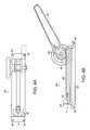
- FIG. 4 aillustrates the horizontal cross-sectional view of a style puller according to the present invention.
- FIG. 4 billustrates the vertical cross-sectional view of a style puller according to the present invention.
- the present inventionrelates generally to the manufacture of small-diameter medical devices. More particularly, the present invention is an apparatus and method for manufacturing small diameter ultrasonic probes capable of vibrating in a transverse mode that can be used in ultrasonic medical devices for tissue ablation.
- Proberefers to a device capable of being adapted to an ultrasonic generator means, which is capable of propagating the energy emitted by the ultrasonic generator means along its length, and is capable of acoustic impedance transformation of ultrasound energy to mechanical energy.
- Transverserefers to vibration of a probe at right angles to the axis of a probe.
- a “transverse wave” as used hereinis a wave propagated along an ultrasonic probe in which the direction of the disturbance at each point of the medium is perpendicular to the wave vector.
- Lead-inrefers to the opening at the mouth of the drawing die.
- “Work hardening” as used hereinrefers to the increase in strength that accompanies plastic deformation of a metal.
- Small diameterrefers to an ultrasonic probe with a diameter less than 0.020 inches.
- “Large diameter” as used hereinrefers to an ultrasonic probe with a diameter greater than or equal to 0.020 inches.
- Memory metalsrefers to metals that return to their original shape if deformed.
- piezoelectric metalsrefers to as metals that relate to or involve piezoelectricity.
- piezoelectricityrefers to the generation of electricity or of electric polarity in dielectric crystals subjected to mechanical stress, or the generation of stress in such crystals subjected to an applied voltage.
- Ductile materialsrefer to materials which are easily molded or shaped; or easily drawn into a wire or hammered.
- the present inventionprovides a manufacturing apparatus and method to fabricate a small diameter ultrasonic probe capable of oscillating in a transverse mode. More particularly, the present invention provides a method of manufacturing probes having a diameter at a functional end of less than 0.020 inches.
- a small diameter ultrasonic probe of the present inventionis shown generally at 1 in FIG. 1 .
- the ultrasonic probe 1includes a probe tip 2 , a functional end 4 and from one to a plurality of transforming elements 8 and 12 .
- the transforming element 12is larger in diameter than the transforming element 8 which is larger in diameter than the functional end 4 of the probe tip 2 .
- Each of the transforming elements 8 and 12are connected by connecting areas 10 which transition from one diameter to the next.
- the functional end 4is connected to the transforming elements 8 and 12 by a connecting area 6 .
- the small diameter ultrasonic probe 1is of sufficient rigidity in order to avoid fracturing or breaking.
- FIG. 2shows another embodiment of a small diameter ultrasonic probe 1 of the present invention.
- the ultrasonic probe 1includes a probe tip 2 , a functional end 4 and from one to a plurality of transforming elements 8 and 12 one larger in diameter than the previous one from the probe tip 1 to the attachable end of the probe 14 .
- the attachable end of the probein one embodiment is attached to a handle 16 .
- Each of the transforming elements 8 and 12are connected by a connecting area 10 which transition from one diameter to the next.
- the functional end 4is connected to the transforming elements 8 and 12 by the connecting area 6 .
- the ultrasonic probe 1is of sufficient flexibility to cause sufficient cavitation energy to cause tissue ablation.
- the ultrasonic probe 1is made from the materials selected from the group including “memory metals”, “piezoelectric materials”, or any material that is “ductile” such as, for example, metals including titanium, titanium alloys or similar materials known to those skilled in the art.
- the ultrasonic probeis made from titanium.
- the ultrasonic probefunctions in a transverse mode.
- FIG. 3shows a cross-sectional view of the drawing die 20 of the present invention.
- the drawing die 20comprises a bell-shaped lead-in 22 on a front side 24 and a bell-shaped lead-in 23 on a back side 25 which allows for the direction of the draw to be reversed for a retrograde draw. Reversal of the direction of the draw allows the functional end 4 of the probe 1 to have a smaller diameter than those of the transforming elements 8 and 12 while being made of one contiguous piece of material to increase the strength and flexibility of the probe.
- the die 20is made from the material selected from the group including, but not limited to, tungsten, stainless steel, carbide, diamond or similar materials known to those skilled in the art. In a preferred embodiment, the drawing die 20 is made from tungsten carbide encased in a stainless steel housing.
- the materialis first machined to provide a diameter greater than or equal to 0.020 inches.
- the machined materialis drawn through the drawing die 20 to reduce the diameter of the functional end 4 while undergoing an annealing process.
- the annealing process of the present inventionincludes exposing the machined material to a change in temperature resulting in decreasing the amount of work hardening and changing the strength of the resulting device.
- the machined materialis drawn through a succession of drawing dies 20 to further reduce the diameter of the functional end 4 by about 1% to about 5% with each draw while undergoing an annealing process.
- the machined materialis drawn through the drawing die 20 to reduce the diameter of the transforming elements 8 and 12 as well as the functional end 4 while undergoing the annealing process.
- the machined materialis drawn through a succession of drawing dies 20 to further reduce the diameter of the transforming elements 8 and 12 as well as the functional end 4 by about 1% to about 5% with each draw while undergoing the annealing process.
- a lubricantselected from the group including, but not limited to, lithium grease, soaps, oils, other greases or similar lubricants known to those skilled in the art is used to lubricate the drawing die 20 while drawing the ultrasonic probe 1 through the die 20 or the plurality of dies 20 .
- a lithium greaseis used to lubricate the drawing die 20 while drawing the ultrasonic probe 1 through the die 20 or the plurality of dies 20 .
- the ultrasonic probe 1is drawn through a succession of the drawing dies 20 manually.
- the ultrasonic probe 1is drawn through the drawing die 20 mechanically using, for example, a die room puller 40 illustrated in FIG. 4 b .
- a die room puller 40 illustrated in FIG. 4 bWorkers skilled in the art will recognize that any type of die room puller or similar device known to those skilled in the art can be used to mechanically draw the medical device through the die.
- the ultrasonic probe 1is drawn through a succession of drawing dies 20 mechanically using the die room puller 40 illustrated in FIG. 4 b.
- the shape of the probe tip 2is formed by the process of forging.
- Forgingis a manufacturing process where a material (i.e., a metal) is pressed, pounded or squeezed under great pressure into high strength parts known as forgings.
- the forging processis normally (but not always) performed hot by preheating the metal to a desired temperature before it is worked on. It is important to note that the forging process is entirely different from a casting (or foundry) process, as the metal used to make forged parts is never melted and poured as in the casting process.
- the shape of the probe tip 2is formed by the process of lathing.
- the lathing processincludes a machine for turning and for shaping articles of wood, metal, or other material, by causing them to revolve while acted upon by a cutting tool.
- the shape of the probe tip 2is formed by the swaging.
- Rotary swagingis a process for reducing the cross-sectional area or otherwise changing the shape of bars, tubes or wires by repeated radial blows with one or more pair of opposed dies.
- Cold swagingcan be performed at room temperature and is effective on thin-walled materials and on smaller reductions of cross sectional area.
- a benefit of the cold swagging processis that the cold working of the material improves the strength of the material.
- hot swagingis done at precise elevated temperatures.
- Heatingis usually accomplished by use of induction heating equipment that allows for close control of heat input and swaging temperature. Greater reductions on heavy walled or difficult alloys are typically done utilizing the hot swaging method. Workers skilled in the art will recognize that any type of mechanical shaping process or similar process known to those skilled in the art can be used to shape the tip of the ultrasonic probe of the present invention.
- the diameter of the functional end 4 of the ultrasonic probe 1is reduced to less than 0.020 inches.
- the smaller diameter of the ultrasonic probe 1results in an increase in the flexibility of the probe 1 .
- FIG. 4 ashows a top cross sectional view of a style puller 30 used to grasp the functional end 4 of the ultrasonic probe 1 and to draw the ultrasonic probe 1 through the die 20 .
- the style puller 30includes a chuck-like grasper 32 to grasp the functional end 4 of the ultrasonic probe 1 . Once securely held by the grasper 32 , the functional end 4 can then be reduced down to a diameter less than 0.020 inch by drawing the medical device through the die 20 or series of dies 20 .
- the style puller 30also comprises four screw plates 34 to attach the style puller 30 to a die room puller 40 .
- FIG. 4 bshows a side cross sectional view of the style puller 30 engaged to a die room puller 40 used to draw the ultrasonic probe 1 through the drawing die 20 .
- the style puller 30comprises a base 44 which is bolted to a table by two ends 42 .
- the style puller 30includes a plurality of teeth 46 which are used in a ratcheting-like method with a handle 50 that is attached to the style puller 40 by a ratcheting screw 48 .
- the plurality of teeth 46are engaged by a ratcheting element 54 as the handle 50 is moved from a first position to a second position whereby the medical device is drawn through the die in a forward direction.
- the style puller 30is bolted to the die room puller 40 by the screw plates 34 .
- the style puller 30draws the functional end 4 of the ultrasonic probe 1 through the drawing die 20 , the die 20 being attached to the die room puller 40 .
- Drawing the ultrasonic probe 1 through the die 20results in a decrease in the diameter of the functional end 4 of the ultrasonic probe 1 .
- the handle 50returns from the second position to the first position, the direction of the draw on the functional end 4 of the ultrasonic probe 1 is reversed. Reversing the direction of the draw through the drawing die 20 is the mechanism by which the difference in diameter between the transforming elements 8 and 12 and the functional end 4 is achieved.
- the ultrasonic probe manufactured by the present inventionis described by Assignee's co-pending U.S. patent applications Ser. No. 09/618,352 and Ser. No. 09/917,471, the entirety of these applications are hereby incorporated by reference.
- the probe manufactured by the present inventionmay be used in conjunction with a flexible sheath assembly, such as those described in Assignee's co-pending U.S. patent application Ser. No. 09/775,908, the entirety of which is hereby incorporated by reference.
- Probes manufactured by the present inventionmay be used in medical procedures including tissue remodeling (disclosed in Assignee's co-pending U.S. patent application Ser. No.
Landscapes
- Engineering & Computer Science (AREA)
- Mechanical Engineering (AREA)
- Health & Medical Sciences (AREA)
- General Health & Medical Sciences (AREA)
- Vascular Medicine (AREA)
- Heart & Thoracic Surgery (AREA)
- Surgery (AREA)
- Life Sciences & Earth Sciences (AREA)
- Biomedical Technology (AREA)
- Nuclear Medicine, Radiotherapy & Molecular Imaging (AREA)
- Medical Informatics (AREA)
- Molecular Biology (AREA)
- Animal Behavior & Ethology (AREA)
- Orthopedic Medicine & Surgery (AREA)
- Public Health (AREA)
- Veterinary Medicine (AREA)
- Surgical Instruments (AREA)
Abstract
Description
Claims (39)
Priority Applications (2)
| Application Number | Priority Date | Filing Date | Title |
|---|---|---|---|
| US10/092,862US6647755B2 (en) | 2001-03-07 | 2002-03-06 | Method for manufacturing small diameter medical devices |
| US10/639,546US20040031308A1 (en) | 2001-03-07 | 2003-08-12 | Apparatus for manufacturing small diameter medical devices |
Applications Claiming Priority (2)
| Application Number | Priority Date | Filing Date | Title |
|---|---|---|---|
| US27403701P | 2001-03-07 | 2001-03-07 | |
| US10/092,862US6647755B2 (en) | 2001-03-07 | 2002-03-06 | Method for manufacturing small diameter medical devices |
Related Child Applications (1)
| Application Number | Title | Priority Date | Filing Date |
|---|---|---|---|
| US10/639,546DivisionUS20040031308A1 (en) | 2001-03-07 | 2003-08-12 | Apparatus for manufacturing small diameter medical devices |
Publications (2)
| Publication Number | Publication Date |
|---|---|
| US20020124617A1 US20020124617A1 (en) | 2002-09-12 |
| US6647755B2true US6647755B2 (en) | 2003-11-18 |
Family
ID=23046502
Family Applications (2)
| Application Number | Title | Priority Date | Filing Date |
|---|---|---|---|
| US10/092,862Expired - Fee RelatedUS6647755B2 (en) | 2001-03-07 | 2002-03-06 | Method for manufacturing small diameter medical devices |
| US10/639,546AbandonedUS20040031308A1 (en) | 2001-03-07 | 2003-08-12 | Apparatus for manufacturing small diameter medical devices |
Family Applications After (1)
| Application Number | Title | Priority Date | Filing Date |
|---|---|---|---|
| US10/639,546AbandonedUS20040031308A1 (en) | 2001-03-07 | 2003-08-12 | Apparatus for manufacturing small diameter medical devices |
Country Status (2)
| Country | Link |
|---|---|
| US (2) | US6647755B2 (en) |
| WO (1) | WO2002070158A1 (en) |
Cited By (29)
| Publication number | Priority date | Publication date | Assignee | Title |
|---|---|---|---|---|
| US20050215942A1 (en)* | 2004-01-29 | 2005-09-29 | Tim Abrahamson | Small vessel ultrasound catheter |
| US7384407B2 (en) | 2001-12-03 | 2008-06-10 | Ekos Corporation | Small vessel ultrasound catheter |
| US7494468B2 (en) | 1999-10-05 | 2009-02-24 | Omnisonics Medical Technologies, Inc. | Ultrasonic medical device operating in a transverse mode |
| US7503895B2 (en) | 1999-10-05 | 2009-03-17 | Omnisonics Medical Technologies, Inc. | Ultrasonic device for tissue ablation and sheath for use therewith |
| US7727178B2 (en) | 2001-12-03 | 2010-06-01 | Ekos Corporation | Catheter with multiple ultrasound radiating members |
| US7771372B2 (en) | 2003-01-03 | 2010-08-10 | Ekos Corporation | Ultrasonic catheter with axial energy field |
| US7774933B2 (en) | 2002-02-28 | 2010-08-17 | Ekos Corporation | Method of manufacturing ultrasound catheters |
| US7794414B2 (en) | 2004-02-09 | 2010-09-14 | Emigrant Bank, N.A. | Apparatus and method for an ultrasonic medical device operating in torsional and transverse modes |
| US20110066083A1 (en)* | 2004-10-28 | 2011-03-17 | Tosaya Carol A | Ultrasonic apparatus and method for treating obesity or fat-deposits or for delivering cosmetic or other bodily therapy |
| US7993308B2 (en) | 2003-04-22 | 2011-08-09 | Ekos Corporation | Ultrasound enhanced central venous catheter |
| US8192391B2 (en) | 2009-07-03 | 2012-06-05 | Ekos Corporation | Power parameters for ultrasonic catheter |
| US8192363B2 (en) | 2006-10-27 | 2012-06-05 | Ekos Corporation | Catheter with multiple ultrasound radiating members |
| US8226629B1 (en) | 2002-04-01 | 2012-07-24 | Ekos Corporation | Ultrasonic catheter power control |
| US8690818B2 (en) | 1997-05-01 | 2014-04-08 | Ekos Corporation | Ultrasound catheter for providing a therapeutic effect to a vessel of a body |
| US8740835B2 (en) | 2010-02-17 | 2014-06-03 | Ekos Corporation | Treatment of vascular occlusions using ultrasonic energy and microbubbles |
| US8764700B2 (en) | 1998-06-29 | 2014-07-01 | Ekos Corporation | Sheath for use with an ultrasound element |
| US8790359B2 (en) | 1999-10-05 | 2014-07-29 | Cybersonics, Inc. | Medical systems and related methods |
| US9044568B2 (en) | 2007-06-22 | 2015-06-02 | Ekos Corporation | Method and apparatus for treatment of intracranial hemorrhages |
| US9107590B2 (en) | 2004-01-29 | 2015-08-18 | Ekos Corporation | Method and apparatus for detecting vascular conditions with a catheter |
| US20160136396A1 (en)* | 2013-09-30 | 2016-05-19 | Abbott Cardiovascular Systems Inc. | Guidewire with varying properties |
| US9579494B2 (en) | 2013-03-14 | 2017-02-28 | Ekos Corporation | Method and apparatus for drug delivery to a target site |
| US10092742B2 (en) | 2014-09-22 | 2018-10-09 | Ekos Corporation | Catheter system |
| US10182833B2 (en) | 2007-01-08 | 2019-01-22 | Ekos Corporation | Power parameters for ultrasonic catheter |
| US10188410B2 (en) | 2007-01-08 | 2019-01-29 | Ekos Corporation | Power parameters for ultrasonic catheter |
| US10232196B2 (en) | 2006-04-24 | 2019-03-19 | Ekos Corporation | Ultrasound therapy system |
| US10656025B2 (en) | 2015-06-10 | 2020-05-19 | Ekos Corporation | Ultrasound catheter |
| US10888657B2 (en) | 2010-08-27 | 2021-01-12 | Ekos Corporation | Method and apparatus for treatment of intracranial hemorrhages |
| US11458290B2 (en) | 2011-05-11 | 2022-10-04 | Ekos Corporation | Ultrasound system |
| US11684759B2 (en) | 2020-01-22 | 2023-06-27 | Abbott Cardiovascular Systems Inc. | Guidewire having varying diameters and method of making |
Families Citing this family (3)
| Publication number | Priority date | Publication date | Assignee | Title |
|---|---|---|---|---|
| EP2177169B1 (en)* | 2008-10-16 | 2016-05-04 | Lain Electronic S.r.L. | Vibrating device for the treatment of adipose tissue |
| CN105962996B (en) | 2016-07-11 | 2019-05-10 | 上海逸思医疗科技有限公司 | An ultrasonic scalpel waveguide rod |
| CN110303059B (en)* | 2019-06-21 | 2024-03-29 | 百利来轧辊(常州)有限公司 | Numerical control wire drawing machine |
Citations (41)
| Publication number | Priority date | Publication date | Assignee | Title |
|---|---|---|---|---|
| US404319A (en)* | 1889-05-28 | Method of drawing wire of one sectional form into wire of another sectional form | ||
| US414090A (en)* | 1889-10-29 | Draw-plate | ||
| US1239451A (en) | 1913-03-17 | 1917-09-11 | Louis C Belz | Process and means for making drawn-wire articles. |
| US1779478A (en) | 1929-02-19 | 1930-10-28 | Union Drawn Steel Company | Method of working metal rods, bars, and the like |
| US2199602A (en)* | 1937-09-22 | 1940-05-07 | American Fork & Hoe Co | Method of forming tubes |
| US3763680A (en) | 1972-08-23 | 1973-10-09 | Cf & I Steel Corp | Method and apparatus for treating wire |
| US3805787A (en) | 1972-06-16 | 1974-04-23 | Surgical Design Corp | Ultrasonic surgical instrument |
| US3962898A (en)* | 1973-04-21 | 1976-06-15 | Berkenhoff & Drebes Gesellschaft Mit Beschrankter Haftung | Apparatus for the manufacture of wire |
| US4462242A (en) | 1980-03-10 | 1984-07-31 | Gk Technologies, Incorporated | Method for wire drawing |
| US4870953A (en) | 1987-11-13 | 1989-10-03 | Donmicheal T Anthony | Intravascular ultrasonic catheter/probe and method for treating intravascular blockage |
| US4872333A (en) | 1985-04-09 | 1989-10-10 | Burnand Richard P | Wire drawing die |
| US4922902A (en) | 1986-05-19 | 1990-05-08 | Valleylab, Inc. | Method for removing cellular material with endoscopic ultrasonic aspirator |
| US4931047A (en) | 1987-09-30 | 1990-06-05 | Cavitron, Inc. | Method and apparatus for providing enhanced tissue fragmentation and/or hemostasis |
| US4989583A (en) | 1988-10-21 | 1991-02-05 | Nestle S.A. | Ultrasonic cutting tip assembly |
| US5058570A (en) | 1986-11-27 | 1991-10-22 | Sumitomo Bakelite Company Limited | Ultrasonic surgical apparatus |
| US5112300A (en) | 1990-04-03 | 1992-05-12 | Alcon Surgical, Inc. | Method and apparatus for controlling ultrasonic fragmentation of body tissue |
| US5180363A (en) | 1989-04-27 | 1993-01-19 | Sumitomo Bakelite Company Company Limited | Operation device |
| US5217465A (en) | 1992-02-28 | 1993-06-08 | Alcon Surgical, Inc. | Flexible and steerable aspiration tip for microsurgery |
| US5255551A (en) | 1992-06-29 | 1993-10-26 | Dennis Vetter | Precious metal wire drawing machine and method |
| US5261805A (en) | 1986-08-15 | 1993-11-16 | Polysystem Machinery Manufacturing Inc. | Die for extrusion of blown plastic film |
| US5325698A (en) | 1992-09-30 | 1994-07-05 | Ford Motor Company | Stepped extrusion die assembly |
| US5421338A (en) | 1988-03-21 | 1995-06-06 | Boston Scientific Corporation | Acoustic imaging catheter and the like |
| US5469853A (en) | 1992-12-11 | 1995-11-28 | Tetrad Corporation | Bendable ultrasonic probe and sheath for use therewith |
| US5492001A (en) | 1994-01-18 | 1996-02-20 | Kabushiki Kaisha Yutaka Giken | Method and apparatus for working burred portion of workpiece |
| US5527273A (en) | 1994-10-06 | 1996-06-18 | Misonix, Inc. | Ultrasonic lipectomy probe and method for manufacture |
| US5676011A (en) | 1996-05-20 | 1997-10-14 | Allison; Jack Y. | Precious metal wire drawing apparatus |
| US5687474A (en) | 1992-04-30 | 1997-11-18 | Vlsi Technology, Inc. | Method of assembling and cooling a package structure with accessible chip |
| US5704787A (en) | 1995-10-20 | 1998-01-06 | San Diego Swiss Machining, Inc. | Hardened ultrasonic dental surgical tips and process |
| US5758420A (en)* | 1993-10-20 | 1998-06-02 | Florida Hospital Supplies, Inc. | Process of manufacturing an aneurysm clip |
| US5765418A (en)* | 1994-05-16 | 1998-06-16 | Medtronic, Inc. | Method for making an implantable medical device from a refractory metal |
| US5803083A (en) | 1995-11-09 | 1998-09-08 | Cordis Corporation | Guiding catheter with ultrasound imaging capability |
| US5820300A (en)* | 1995-02-21 | 1998-10-13 | Mitsubishi Jukogyo Kabushiki Kaisha | CO2 sea bottom throw-away system |
| US5840151A (en) | 1993-02-04 | 1998-11-24 | Baxter International Inc. | Apparatus and dies for forming peelable tube assemblies |
| US5981444A (en)* | 1987-02-05 | 1999-11-09 | Sumitomo Electric Industries, Ltd. | Process for manufacturing a superconducting wire of compound oxide-type ceramics |
| US5993408A (en) | 1997-10-03 | 1999-11-30 | Allergan Sales, Inc. | Thin tip phaco needle |
| US6062059A (en) | 1995-07-07 | 2000-05-16 | Ailsa Investments Limited | Manufacture of extrusion dies |
| US6107161A (en) | 1996-06-07 | 2000-08-22 | Rohm Co., Ltd. | Semiconductor chip and a method for manufacturing thereof |
| US6124546A (en) | 1997-12-03 | 2000-09-26 | Advanced Micro Devices, Inc. | Integrated circuit chip package and method of making the same |
| US6124150A (en) | 1998-08-20 | 2000-09-26 | Micron Technology, Inc. | Transverse hybrid LOC package |
| US6124634A (en) | 1996-03-07 | 2000-09-26 | Micron Technology, Inc. | Micromachined chip scale package |
| US6307156B1 (en)* | 1997-05-02 | 2001-10-23 | General Science And Technology Corp. | High flexibility and heat dissipating coaxial cable |
Family Cites Families (6)
| Publication number | Priority date | Publication date | Assignee | Title |
|---|---|---|---|---|
| US323762A (en)* | 1885-08-04 | white | ||
| US168975A (en)* | 1875-10-19 | Improvement in machines for drawing and polishing bars | ||
| US2843176A (en)* | 1953-08-28 | 1958-07-15 | Imp Brass Mfg Co | Draw-type tube straightener with clamping means allowing tube to be laterally inserted and removed |
| US3241780A (en)* | 1963-08-05 | 1966-03-22 | Indiana Steel & Wire Company I | Wire tensioning filament feeding apparatus |
| US3486361A (en)* | 1967-07-20 | 1969-12-30 | Babcock & Wilcox Co | Strengthening of elongated metal sections |
| US5709120A (en)* | 1996-02-23 | 1998-01-20 | Shilling; Paul L. | Straight line drawing device |
- 2002
- 2002-03-06WOPCT/US2002/007135patent/WO2002070158A1/ennot_activeApplication Discontinuation
- 2002-03-06USUS10/092,862patent/US6647755B2/ennot_activeExpired - Fee Related
- 2003
- 2003-08-12USUS10/639,546patent/US20040031308A1/ennot_activeAbandoned
Patent Citations (42)
| Publication number | Priority date | Publication date | Assignee | Title |
|---|---|---|---|---|
| US404319A (en)* | 1889-05-28 | Method of drawing wire of one sectional form into wire of another sectional form | ||
| US414090A (en)* | 1889-10-29 | Draw-plate | ||
| US1239451A (en) | 1913-03-17 | 1917-09-11 | Louis C Belz | Process and means for making drawn-wire articles. |
| US1779478A (en) | 1929-02-19 | 1930-10-28 | Union Drawn Steel Company | Method of working metal rods, bars, and the like |
| US2199602A (en)* | 1937-09-22 | 1940-05-07 | American Fork & Hoe Co | Method of forming tubes |
| US3805787A (en) | 1972-06-16 | 1974-04-23 | Surgical Design Corp | Ultrasonic surgical instrument |
| US3763680A (en) | 1972-08-23 | 1973-10-09 | Cf & I Steel Corp | Method and apparatus for treating wire |
| US3962898A (en)* | 1973-04-21 | 1976-06-15 | Berkenhoff & Drebes Gesellschaft Mit Beschrankter Haftung | Apparatus for the manufacture of wire |
| US4462242A (en) | 1980-03-10 | 1984-07-31 | Gk Technologies, Incorporated | Method for wire drawing |
| US4462242B1 (en) | 1980-03-10 | 1988-07-26 | ||
| US4872333A (en) | 1985-04-09 | 1989-10-10 | Burnand Richard P | Wire drawing die |
| US4922902A (en) | 1986-05-19 | 1990-05-08 | Valleylab, Inc. | Method for removing cellular material with endoscopic ultrasonic aspirator |
| US5261805A (en) | 1986-08-15 | 1993-11-16 | Polysystem Machinery Manufacturing Inc. | Die for extrusion of blown plastic film |
| US5058570A (en) | 1986-11-27 | 1991-10-22 | Sumitomo Bakelite Company Limited | Ultrasonic surgical apparatus |
| US5981444A (en)* | 1987-02-05 | 1999-11-09 | Sumitomo Electric Industries, Ltd. | Process for manufacturing a superconducting wire of compound oxide-type ceramics |
| US4931047A (en) | 1987-09-30 | 1990-06-05 | Cavitron, Inc. | Method and apparatus for providing enhanced tissue fragmentation and/or hemostasis |
| US4870953A (en) | 1987-11-13 | 1989-10-03 | Donmicheal T Anthony | Intravascular ultrasonic catheter/probe and method for treating intravascular blockage |
| US5421338A (en) | 1988-03-21 | 1995-06-06 | Boston Scientific Corporation | Acoustic imaging catheter and the like |
| US4989583A (en) | 1988-10-21 | 1991-02-05 | Nestle S.A. | Ultrasonic cutting tip assembly |
| US5180363A (en) | 1989-04-27 | 1993-01-19 | Sumitomo Bakelite Company Company Limited | Operation device |
| US5112300A (en) | 1990-04-03 | 1992-05-12 | Alcon Surgical, Inc. | Method and apparatus for controlling ultrasonic fragmentation of body tissue |
| US5217465A (en) | 1992-02-28 | 1993-06-08 | Alcon Surgical, Inc. | Flexible and steerable aspiration tip for microsurgery |
| US5687474A (en) | 1992-04-30 | 1997-11-18 | Vlsi Technology, Inc. | Method of assembling and cooling a package structure with accessible chip |
| US5255551A (en) | 1992-06-29 | 1993-10-26 | Dennis Vetter | Precious metal wire drawing machine and method |
| US5325698A (en) | 1992-09-30 | 1994-07-05 | Ford Motor Company | Stepped extrusion die assembly |
| US5469853A (en) | 1992-12-11 | 1995-11-28 | Tetrad Corporation | Bendable ultrasonic probe and sheath for use therewith |
| US5840151A (en) | 1993-02-04 | 1998-11-24 | Baxter International Inc. | Apparatus and dies for forming peelable tube assemblies |
| US5758420A (en)* | 1993-10-20 | 1998-06-02 | Florida Hospital Supplies, Inc. | Process of manufacturing an aneurysm clip |
| US5492001A (en) | 1994-01-18 | 1996-02-20 | Kabushiki Kaisha Yutaka Giken | Method and apparatus for working burred portion of workpiece |
| US5765418A (en)* | 1994-05-16 | 1998-06-16 | Medtronic, Inc. | Method for making an implantable medical device from a refractory metal |
| US5527273A (en) | 1994-10-06 | 1996-06-18 | Misonix, Inc. | Ultrasonic lipectomy probe and method for manufacture |
| US5820300A (en)* | 1995-02-21 | 1998-10-13 | Mitsubishi Jukogyo Kabushiki Kaisha | CO2 sea bottom throw-away system |
| US6062059A (en) | 1995-07-07 | 2000-05-16 | Ailsa Investments Limited | Manufacture of extrusion dies |
| US5704787A (en) | 1995-10-20 | 1998-01-06 | San Diego Swiss Machining, Inc. | Hardened ultrasonic dental surgical tips and process |
| US5803083A (en) | 1995-11-09 | 1998-09-08 | Cordis Corporation | Guiding catheter with ultrasound imaging capability |
| US6124634A (en) | 1996-03-07 | 2000-09-26 | Micron Technology, Inc. | Micromachined chip scale package |
| US5676011A (en) | 1996-05-20 | 1997-10-14 | Allison; Jack Y. | Precious metal wire drawing apparatus |
| US6107161A (en) | 1996-06-07 | 2000-08-22 | Rohm Co., Ltd. | Semiconductor chip and a method for manufacturing thereof |
| US6307156B1 (en)* | 1997-05-02 | 2001-10-23 | General Science And Technology Corp. | High flexibility and heat dissipating coaxial cable |
| US5993408A (en) | 1997-10-03 | 1999-11-30 | Allergan Sales, Inc. | Thin tip phaco needle |
| US6124546A (en) | 1997-12-03 | 2000-09-26 | Advanced Micro Devices, Inc. | Integrated circuit chip package and method of making the same |
| US6124150A (en) | 1998-08-20 | 2000-09-26 | Micron Technology, Inc. | Transverse hybrid LOC package |
Non-Patent Citations (1)
| Title |
|---|
| PCT International Search Report for International Application No. PCT/US02/07135 dated Jun. 5, 2002. |
Cited By (47)
| Publication number | Priority date | Publication date | Assignee | Title |
|---|---|---|---|---|
| US8690818B2 (en) | 1997-05-01 | 2014-04-08 | Ekos Corporation | Ultrasound catheter for providing a therapeutic effect to a vessel of a body |
| US8764700B2 (en) | 1998-06-29 | 2014-07-01 | Ekos Corporation | Sheath for use with an ultrasound element |
| US8790359B2 (en) | 1999-10-05 | 2014-07-29 | Cybersonics, Inc. | Medical systems and related methods |
| US7494468B2 (en) | 1999-10-05 | 2009-02-24 | Omnisonics Medical Technologies, Inc. | Ultrasonic medical device operating in a transverse mode |
| US7503895B2 (en) | 1999-10-05 | 2009-03-17 | Omnisonics Medical Technologies, Inc. | Ultrasonic device for tissue ablation and sheath for use therewith |
| US7828762B2 (en) | 2001-12-03 | 2010-11-09 | Ekos Corporation | Catheter with multiple ultrasound radiating members |
| US7727178B2 (en) | 2001-12-03 | 2010-06-01 | Ekos Corporation | Catheter with multiple ultrasound radiating members |
| US10926074B2 (en) | 2001-12-03 | 2021-02-23 | Ekos Corporation | Catheter with multiple ultrasound radiating members |
| US7384407B2 (en) | 2001-12-03 | 2008-06-10 | Ekos Corporation | Small vessel ultrasound catheter |
| US10080878B2 (en) | 2001-12-03 | 2018-09-25 | Ekos Corporation | Catheter with multiple ultrasound radiating members |
| US8696612B2 (en) | 2001-12-03 | 2014-04-15 | Ekos Corporation | Catheter with multiple ultrasound radiating members |
| US8167831B2 (en) | 2001-12-03 | 2012-05-01 | Ekos Corporation | Catheter with multiple ultrasound radiating members |
| US9415242B2 (en) | 2001-12-03 | 2016-08-16 | Ekos Corporation | Catheter with multiple ultrasound radiating members |
| US7774933B2 (en) | 2002-02-28 | 2010-08-17 | Ekos Corporation | Method of manufacturing ultrasound catheters |
| US9943675B1 (en) | 2002-04-01 | 2018-04-17 | Ekos Corporation | Ultrasonic catheter power control |
| US8226629B1 (en) | 2002-04-01 | 2012-07-24 | Ekos Corporation | Ultrasonic catheter power control |
| US8852166B1 (en) | 2002-04-01 | 2014-10-07 | Ekos Corporation | Ultrasonic catheter power control |
| US7771372B2 (en) | 2003-01-03 | 2010-08-10 | Ekos Corporation | Ultrasonic catheter with axial energy field |
| US7993308B2 (en) | 2003-04-22 | 2011-08-09 | Ekos Corporation | Ultrasound enhanced central venous catheter |
| US9107590B2 (en) | 2004-01-29 | 2015-08-18 | Ekos Corporation | Method and apparatus for detecting vascular conditions with a catheter |
| US20050215942A1 (en)* | 2004-01-29 | 2005-09-29 | Tim Abrahamson | Small vessel ultrasound catheter |
| US7794414B2 (en) | 2004-02-09 | 2010-09-14 | Emigrant Bank, N.A. | Apparatus and method for an ultrasonic medical device operating in torsional and transverse modes |
| US20110066083A1 (en)* | 2004-10-28 | 2011-03-17 | Tosaya Carol A | Ultrasonic apparatus and method for treating obesity or fat-deposits or for delivering cosmetic or other bodily therapy |
| US12186595B2 (en) | 2006-04-24 | 2025-01-07 | Boston Scientific Scimed, Inc. | Ultrasound therapy system |
| US12064650B2 (en) | 2006-04-24 | 2024-08-20 | Ekos Corporation | Ultrasound therapy system |
| US11058901B2 (en) | 2006-04-24 | 2021-07-13 | Ekos Corporation | Ultrasound therapy system |
| US10232196B2 (en) | 2006-04-24 | 2019-03-19 | Ekos Corporation | Ultrasound therapy system |
| US8192363B2 (en) | 2006-10-27 | 2012-06-05 | Ekos Corporation | Catheter with multiple ultrasound radiating members |
| US10188410B2 (en) | 2007-01-08 | 2019-01-29 | Ekos Corporation | Power parameters for ultrasonic catheter |
| US10182833B2 (en) | 2007-01-08 | 2019-01-22 | Ekos Corporation | Power parameters for ultrasonic catheter |
| US11925367B2 (en) | 2007-01-08 | 2024-03-12 | Ekos Corporation | Power parameters for ultrasonic catheter |
| US11672553B2 (en) | 2007-06-22 | 2023-06-13 | Ekos Corporation | Method and apparatus for treatment of intracranial hemorrhages |
| US9044568B2 (en) | 2007-06-22 | 2015-06-02 | Ekos Corporation | Method and apparatus for treatment of intracranial hemorrhages |
| US9849273B2 (en) | 2009-07-03 | 2017-12-26 | Ekos Corporation | Power parameters for ultrasonic catheter |
| US8192391B2 (en) | 2009-07-03 | 2012-06-05 | Ekos Corporation | Power parameters for ultrasonic catheter |
| US9192566B2 (en) | 2010-02-17 | 2015-11-24 | Ekos Corporation | Treatment of vascular occlusions using ultrasonic energy and microbubbles |
| US8740835B2 (en) | 2010-02-17 | 2014-06-03 | Ekos Corporation | Treatment of vascular occlusions using ultrasonic energy and microbubbles |
| US10888657B2 (en) | 2010-08-27 | 2021-01-12 | Ekos Corporation | Method and apparatus for treatment of intracranial hemorrhages |
| US11458290B2 (en) | 2011-05-11 | 2022-10-04 | Ekos Corporation | Ultrasound system |
| US9579494B2 (en) | 2013-03-14 | 2017-02-28 | Ekos Corporation | Method and apparatus for drug delivery to a target site |
| US20160136396A1 (en)* | 2013-09-30 | 2016-05-19 | Abbott Cardiovascular Systems Inc. | Guidewire with varying properties |
| US10335580B2 (en)* | 2013-09-30 | 2019-07-02 | Abbott Cardiovascular Systems Inc. | Guidewire with varying properties |
| US10507320B2 (en) | 2014-09-22 | 2019-12-17 | Ekos Corporation | Catheter system |
| US10092742B2 (en) | 2014-09-22 | 2018-10-09 | Ekos Corporation | Catheter system |
| US11740138B2 (en) | 2015-06-10 | 2023-08-29 | Ekos Corporation | Ultrasound catheter |
| US10656025B2 (en) | 2015-06-10 | 2020-05-19 | Ekos Corporation | Ultrasound catheter |
| US11684759B2 (en) | 2020-01-22 | 2023-06-27 | Abbott Cardiovascular Systems Inc. | Guidewire having varying diameters and method of making |
Also Published As
| Publication number | Publication date |
|---|---|
| US20020124617A1 (en) | 2002-09-12 |
| US20040031308A1 (en) | 2004-02-19 |
| WO2002070158A1 (en) | 2002-09-12 |
Similar Documents
| Publication | Publication Date | Title |
|---|---|---|
| US6647755B2 (en) | Method for manufacturing small diameter medical devices | |
| US20210316334A1 (en) | Method and system for generating mechanical pulses | |
| US6277084B1 (en) | Ultrasonic medical device | |
| EP1960123B1 (en) | Methods for producing ultrasonic waveguides having improved amplification | |
| US8459122B2 (en) | Amplifying ultrasonic waveguides | |
| EP0784451B1 (en) | Ultrasonic lipectomy probe | |
| US8926630B2 (en) | Device and method for fragmenting and removing concretions from body ducts and cavities | |
| AU770503B2 (en) | Ultrasonic medical device operating in a transverse mode | |
| US20030065263A1 (en) | Ultrasonic probe device with rapid attachment and detachment means having a line contact collet | |
| JP2005505344A (en) | Ultrasonic probe device comprising a quick attachment means and a detachment means having a line contact collet | |
| US20160287277A1 (en) | Devices and methods for removing occlusions from a bodily cavity | |
| WO1987001575A1 (en) | Ultrasonic instrument for surgical operations | |
| JP2012501762A (en) | Endodontic device and manufacturing method | |
| CA2299997A1 (en) | Method and apparatus for cleaning medical instruments and the like | |
| JP2012501762A5 (en) | ||
| US11230758B2 (en) | Tip for an ultrasonic surgical tool with case hardened cutting edges and method of making same | |
| JPH05111493A (en) | Implement for surgical operation | |
| DE102022126990A1 (en) | Hollow probe for a lithotripsy device, lithotripsy device for crushing body stones, retrofit kit and method for manufacturing a hollow probe | |
| EP4419021A1 (en) | Application probe for breaking up calculi for a lithotripsy device, lithotripsy device, lithotripsy system and method for operating a lithotripsy device | |
| JPH0333011B2 (en) | ||
| AU2002348422A1 (en) | Ultrasonic probe device with rapid attachment and detachment means having a line contact collet |
Legal Events
| Date | Code | Title | Description |
|---|---|---|---|
| AS | Assignment | Owner name:OMNISONICS MEDICAL TECHNOLOGIES, INC., MASSACHUSET Free format text:ASSIGNMENT OF ASSIGNORS INTEREST;ASSIGNORS:RABINER, ROBERT A.;HARE, BRADLEY A.;PRASAD, JANNIAH;REEL/FRAME:012943/0722 Effective date:20020514 | |
| FEPP | Fee payment procedure | Free format text:PAYOR NUMBER ASSIGNED (ORIGINAL EVENT CODE: ASPN); ENTITY STATUS OF PATENT OWNER: SMALL ENTITY | |
| FPAY | Fee payment | Year of fee payment:4 | |
| FEPP | Fee payment procedure | Free format text:PAYER NUMBER DE-ASSIGNED (ORIGINAL EVENT CODE: RMPN); ENTITY STATUS OF PATENT OWNER: SMALL ENTITY Free format text:PAYOR NUMBER ASSIGNED (ORIGINAL EVENT CODE: ASPN); ENTITY STATUS OF PATENT OWNER: SMALL ENTITY | |
| AS | Assignment | Owner name:EMIGRANT BANK, N.A.,NEW YORK Free format text:ASSIGNMENT OF ASSIGNORS INTEREST;ASSIGNOR:OMNISONICS MEDICAL TECHNOLOGIES, INC.;REEL/FRAME:024035/0138 Effective date:20091118 Owner name:EMIGRANT BANK, N.A., NEW YORK Free format text:ASSIGNMENT OF ASSIGNORS INTEREST;ASSIGNOR:OMNISONICS MEDICAL TECHNOLOGIES, INC.;REEL/FRAME:024035/0138 Effective date:20091118 | |
| AS | Assignment | Owner name:CYBERSONICS, INC., PENNSYLVANIA Free format text:ASSIGNMENT OF ASSIGNORS INTEREST;ASSIGNOR:EMIGRANT BANK, N.A.;REEL/FRAME:025779/0820 Effective date:20101201 | |
| AS | Assignment | Owner name:EMIGRANT BANK, N.A., NEW YORK Free format text:SECURITY AGREEMENT;ASSIGNOR:CYBERSONICS, INC.;REEL/FRAME:025879/0635 Effective date:20101201 | |
| FPAY | Fee payment | Year of fee payment:8 | |
| REMI | Maintenance fee reminder mailed | ||
| LAPS | Lapse for failure to pay maintenance fees | ||
| STCH | Information on status: patent discontinuation | Free format text:PATENT EXPIRED DUE TO NONPAYMENT OF MAINTENANCE FEES UNDER 37 CFR 1.362 | |
| FP | Lapsed due to failure to pay maintenance fee | Effective date:20151118 |