US6647303B1 - Feeder/programming/buffer control system and control method - Google Patents
Feeder/programming/buffer control system and control methodDownload PDFInfo
- Publication number
- US6647303B1 US6647303B1US09/418,901US41890199AUS6647303B1US 6647303 B1US6647303 B1US 6647303B1US 41890199 AUS41890199 AUS 41890199AUS 6647303 B1US6647303 B1US 6647303B1
- Authority
- US
- United States
- Prior art keywords
- control
- programming
- controlling
- subsystem
- control agent
- Prior art date
- Legal status (The legal status is an assumption and is not a legal conclusion. Google has not performed a legal analysis and makes no representation as to the accuracy of the status listed.)
- Expired - Fee Related
Links
- 238000000034methodMethods0.000titleclaimsabstractdescription29
- 239000000872bufferSubstances0.000titleabstractdescription17
- 230000007246mechanismEffects0.000claimsabstractdescription100
- 238000012545processingMethods0.000claimsdescription52
- 230000015654memoryEffects0.000claimsdescription33
- 239000000523sampleSubstances0.000claimsdescription14
- 238000004891communicationMethods0.000claimsdescription10
- 238000012360testing methodMethods0.000claimsdescription8
- 230000008569processEffects0.000claimsdescription6
- 238000005259measurementMethods0.000claimsdescription4
- 230000004044responseEffects0.000claims2
- 239000003795chemical substances by applicationSubstances0.000abstractdescription38
- 238000004519manufacturing processMethods0.000abstractdescription37
- 239000007853buffer solutionSubstances0.000abstractdescription24
- 230000006870functionEffects0.000description3
- 230000002950deficientEffects0.000description2
- 238000010586diagramMethods0.000description2
- 238000012986modificationMethods0.000description2
- 230000004048modificationEffects0.000description2
- 238000013024troubleshootingMethods0.000description2
- 229930091051ArenineNatural products0.000description1
- 238000003491arrayMethods0.000description1
- 238000010924continuous productionMethods0.000description1
- 230000008021depositionEffects0.000description1
- 238000013461designMethods0.000description1
- 230000006872improvementEffects0.000description1
- 238000003780insertionMethods0.000description1
- 230000037431insertionEffects0.000description1
- 230000010354integrationEffects0.000description1
- 230000008520organizationEffects0.000description1
- 238000004064recyclingMethods0.000description1
- 239000000243solutionSubstances0.000description1
- 238000012795verificationMethods0.000description1
- 239000002699waste materialSubstances0.000description1
Images

Classifications
- G—PHYSICS
- G05—CONTROLLING; REGULATING
- G05B—CONTROL OR REGULATING SYSTEMS IN GENERAL; FUNCTIONAL ELEMENTS OF SUCH SYSTEMS; MONITORING OR TESTING ARRANGEMENTS FOR SUCH SYSTEMS OR ELEMENTS
- G05B19/00—Programme-control systems
- G05B19/02—Programme-control systems electric
- G05B19/418—Total factory control, i.e. centrally controlling a plurality of machines, e.g. direct or distributed numerical control [DNC], flexible manufacturing systems [FMS], integrated manufacturing systems [IMS] or computer integrated manufacturing [CIM]
- G05B19/41815—Total factory control, i.e. centrally controlling a plurality of machines, e.g. direct or distributed numerical control [DNC], flexible manufacturing systems [FMS], integrated manufacturing systems [IMS] or computer integrated manufacturing [CIM] characterised by the cooperation between machine tools, manipulators and conveyor or other workpiece supply system, workcell
- G—PHYSICS
- G05—CONTROLLING; REGULATING
- G05B—CONTROL OR REGULATING SYSTEMS IN GENERAL; FUNCTIONAL ELEMENTS OF SUCH SYSTEMS; MONITORING OR TESTING ARRANGEMENTS FOR SUCH SYSTEMS OR ELEMENTS
- G05B19/00—Programme-control systems
- G05B19/02—Programme-control systems electric
- G05B19/418—Total factory control, i.e. centrally controlling a plurality of machines, e.g. direct or distributed numerical control [DNC], flexible manufacturing systems [FMS], integrated manufacturing systems [IMS] or computer integrated manufacturing [CIM]
- G05B19/41805—Total factory control, i.e. centrally controlling a plurality of machines, e.g. direct or distributed numerical control [DNC], flexible manufacturing systems [FMS], integrated manufacturing systems [IMS] or computer integrated manufacturing [CIM] characterised by assembly
- Y—GENERAL TAGGING OF NEW TECHNOLOGICAL DEVELOPMENTS; GENERAL TAGGING OF CROSS-SECTIONAL TECHNOLOGIES SPANNING OVER SEVERAL SECTIONS OF THE IPC; TECHNICAL SUBJECTS COVERED BY FORMER USPC CROSS-REFERENCE ART COLLECTIONS [XRACs] AND DIGESTS
- Y02—TECHNOLOGIES OR APPLICATIONS FOR MITIGATION OR ADAPTATION AGAINST CLIMATE CHANGE
- Y02P—CLIMATE CHANGE MITIGATION TECHNOLOGIES IN THE PRODUCTION OR PROCESSING OF GOODS
- Y02P90/00—Enabling technologies with a potential contribution to greenhouse gas [GHG] emissions mitigation
- Y02P90/02—Total factory control, e.g. smart factories, flexible manufacturing systems [FMS] or integrated manufacturing systems [IMS]
Definitions
- the present inventionrelates generally to a manufacturing system for electronic products, and more particularly to continuous production of electronic circuit boards incorporating programmable integrated circuits.
- the programming equipmentwas relatively large and bulky. This was because of the need to accurately insert and remove programmable devices at high speeds into and out of programming sockets in the programmer. Since insertion and removal required relatively long traverses at high speed and very precise positioning, very rigid robotic handling equipment was required. This rigidity requirement meant that the various components had to be relatively massive with strong structural support members to maintain structural integrity and precision positioning of the pick and place system moving at high speeds. Due to the size of the programming equipment and the limited space for the even larger assembly equipment, they were located in different areas.
- a single high-speed production assembly systemcould use up programmed devices faster than they could be programmed on a single programming mechanism.
- a major problem associated with programming the programmable devices in a separate area and then bringing the programmed devices into the production assembly area to be inserted into the electronic circuit boardswas that it was difficult to have two separate processes running in different areas and to coordinate between the two separate systems. Often, the production assembly line would run out of programmable devices and the entire production assembly line would have to be shut down. At other times, the programming equipment would be used to program a sufficient inventory of programmed devices to assure that the production assembly line would not be shut down; however, this increased inventory costs. Further problems were created when the programming had to be changed and there was a large inventory of programmed integrated circuits on hand. In this situation, the inventory of programmable devices would have to be reprogrammed with an accompanying waste of time and money.
- any programmer integrated with the production assembly linewould apparently also have to interface with the control software and electronics of the production system software for communication and scheduling purposes. This would be a problem because production assembly line system software was not only complex, but also confidential and/or proprietary to the manufacturers of those systems. This meant that the integration must be done with the cooperation of the manufacturers, who were reluctant to spend engineering effort on anything but improving their own systems, or must be done with a lot of engineering effort expended on understanding the manufacturers' software before working on the programmer's control software.
- the ideal systemneeded to be able to accommodate a number of different micro device feeding mechanisms including tape, tube, and tray feeders.
- the present inventionprovides a control system having a control agent controlling a user interface, a robotic control, a processing control, and a job control.
- the control systemis used with a feeder/processing/buffer system which has a feeder mechanism for presenting micro devices, a robotic handling mechanism for manipulating the micro devices among the other mechanisms, a processing mechanism for performing a processing operation on the micro devices at a high rate of speed, and a buffer mechanism for providing the processed micro devices to the production assembly line on a continuous basis.
- the systemsubstantially solves all the problems which previously faced such systems.
- the present inventionfurther provides a control agent controlling a plurality of subsystems.
- the control agentis used with a feeder/processing/buffer system which has a feeder mechanism for presenting micro devices, a robotic handling mechanism for manipulating the micro devices among the other mechanisms, a processing mechanism for performing a processing operation on the micro devices at a high rate of speed, and a buffer mechanism for providing the processed micro devices to the production assembly line on a continuous basis.
- the systemsubstantially solves all the problems which previously faced such systems.
- the present inventionfurther provides a control agent controlling an error manager subsystem.
- the error manager subsystemis used for efficiently managing errors in a feeder/processing/buffer system which has a feeder mechanism for presenting micro devices, a robotic handling mechanism for manipulating the micro devices among the other mechanisms, a processing mechanism for performing a processing operation on the micro devices at a high rate of speed, and a buffer mechanism for providing the processed micro devices to the production assembly line on a continuous basis.
- the systemsubstantially solves all the problems which previously faced such systems.
- the present inventionfurther provides a control agent controlling an event log subsystem.
- the even log subsystemis used for maintaining a history log of the operations of a feeder/processing/buffer system which has a feeder mechanism for presenting micro devices, a robotic handling mechanism for manipulating the micro devices among the other mechanisms, a processing mechanism for performing a processing operation on the micro devices at a high rate of speed, and a buffer mechanism for providing the processed micro devices to the production assembly line on a continuous basis.
- the systemsubstantially solves all the problems which previously faced such systems.
- the present inventionfurther provides a control agent controlling a non-volatile memory subsystem.
- the non-volatile memory subsystemis used for maintaining operation information across power cycles regarding a feeder/processing/buffer system which has a feeder mechanism for presenting micro devices, a robotic handling mechanism for manipulating the micro devices among the other mechanisms, a processing mechanism for performing a processing operation on the micro devices at a high rate of speed, and a buffer mechanism for providing the processed micro devices to the production assembly line on a continuous basis.
- the systemsubstantially solves all the problems which previously faced such systems.
- the present inventionfurther provides a control agent controlling a programmable memory subsystem.
- the programmable memory subsystemis used for updating operation information regarding a feeder/programming/buffer system which has a feeder mechanism for presenting micro devices, a robotic handling mechanism for manipulating the micro devices among the other mechanisms, a processing mechanism for performing a programming operation on the micro devices at a high rate of speed, and a buffer mechanism for providing the programmed micro devices to the production assembly line on a continuous basis.
- the systemsubstantially solves all the problems which previously faced such systems.
- the present inventionfurther provides a control agent controlling a communications network subsystem.
- the communications network subsystemis used for communicating information to and regarding a feeder/processing/buffer system which has a feeder mechanism for presenting micro devices, a robotic handling mechanism for manipulating the micro devices among the other mechanisms, a processing mechanism for performing a processing operation on the micro devices at a high rate of speed, and a buffer mechanism for providing the processed micro devices to the production assembly line on a continuous basis.
- the systemsubstantially solves all the problems which previously faced such systems.
- the present inventionfurther provides a control agent controlling a portable memory manager.
- the portable memory manageruses a PCMCIA card and is used for updating operation information regarding a feeder/processing/buffer system which has a feeder mechanism for presenting micro devices, a robotic handling mechanism for manipulating the micro devices among the other mechanisms, a processing mechanism for performing a processing operation on the micro devices at a high rate of speed, and a buffer mechanism for providing the processed micro devices to the production assembly line on a continuous basis.
- the systemsubstantially solves all the problems which previously faced such systems.
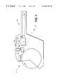
- FIG. 1is a schematic of a feeder/programming/buffer system of the present invention
- FIG. 2is an overall schematic of the control system of the present invention.
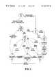
- FIG. 3is a state diagram of the operation of the present invention.
- the feeder/programming/buffer system 10consists of an input feeder mechanism 11 for providing unprogrammed programmable devices (not shown), a robotic handling system 12 for manipulating the programmable devices in the system, a programming mechanism 13 for programming the programmable devices, and an output buffer mechanism 14 for presenting the programmed programmable devices for an assembly system (not shown).
- the feeder/programming/buffer system 10is described in greater detail in the Bolotin applications, supra, but any system having similar mechanisms for performing similar finctions could incorporate the present invention.
- control system 15which controls the operations of the feeder/programming/buffer system 10 .
- the control system 15is controlled by a control agent 16 , which is called a control agent since it sits over other components and subsystems for performing various subsystem operations.
- the control agent 16is connected to a user interface subsystem 20 which allows a user to input instructions regarding setup, to respond to warnings, and to start/stop the operation of the feeder/programming/buffer system 10 .
- the user interface subsystem 20further is interconnected to a display 21 , a keypad 22 , and a plurality of menu selectors 23 which step the user through the setup and the changing of various functions and/or parameters.
- the control agent 16is further connected to a robotic control subsystem 30 for the robotic handling system 12 .
- the robotic handling system 12performs a number of different functions which are controlled by the robotic control subsystem 30 .
- the robotic control subsystem 30operates an input unit 31 , an output unit 32 , a programming actuator unit 33 , a robotic handling unit 34 , a reject bin monitor 35 , a product statistics unit 36 , and a probe control unit 37 .
- the input unit 31provides unprogrammed programmable devices.
- the input unit 31controls the feed of a reel with a support tape having a plurality of pockets with each pocket containing an unprogrammed programmable device.
- the robotic handling unit 34controls a movable carrier and the probe control unit 37 controls a plurality of probes on the carrier which are capable of picking the unprogrammed programmable device out of the pocket.
- the input unit 31controls the advance of the tape to the next unprogrammed programmable device for the next of the plurality of probes under the control of the probe control unit 37 to pick up.
- the unprogrammed programmable deviceis placed in the programming mechanism 13 and the programming actuator unit 33 operates a mechanism which engages unprogrammed programmable devices and disengages programmed programmable devices from the programming mechanism 13 .
- the robotic handling unit 34 and the probe control unit 37cause the programmed programmable devices to be placed on the output buffer mechanism 14 , which is under the control of the output unit 32 .
- Defective programmable devices which cannot be programmedare noted by the reject bin monitor 35 and placed in a reject bin (not shown).
- the output unit 32in one mode controls a conveyor which runs under the robotic handling system 12 for the deposition of programmed programmable devices.
- the output unit 32is set up to deliver a programmed programmable device when one has been removed from the conveyor by the production assembly line handling equipment (not shown).
- the product statistics unit 36keeps track of how long the feeder/programming/buffer system 10 has been turned on, and the total number of programmable devices that have been programmed.
- the control agent 16is further connected to a programming control subsystem 40 which controls the programming mechanism 13 .
- the programming control subsystem 40is connected to a device operation unit 41 , a programming algorithm unit 42 , a socket manager unit 43 , and a programming electronics unit 44 .
- the device operation unit 41sets up the power and ground required for the programmable device.
- the programming algorithm unit 42determines the particular programmable device being programmed and its operational requirements.
- the socket manager unit 43provides information for the programming algorithm unit 42 and the programming electronics unit 44 for the purpose of functionally enabling and disabling individual sockets; if there is a problem with the socket, the units will cause the socket to be by passed.
- the programming electronics unit 44provides the programming for the unprogrammed programmable devices.
- the control agent 16is further connected to a job manager control 50 which is responsible for managing a particular job.
- the information related to the particular jobis described in a job information module 51 .
- the job information module 51is a database which contains the following information: job statistics 52 , serialization data 53 , device data 54 , job parameters 55 , and an executable data 56 .
- the job statistics 52relate to the programmable devices that have been programmed, such as how many good programmable devices, how many rejects, what type of failures, yield, and any other information desired about the programming of those programmable devices.
- the programmable devicessuch as microprocessors, might have serial numbers
- the serialization informationis part of the serialization data 53 .
- the device data 54contains data regarding the programmable device itself.
- the job parameters 55consist of the operations to be done, such as whether a part is to be erased, a continuity test is to be performed, an illegal bit check is to be made, or a verification of the programmable device to be performed after programming, etc.
- the executable data 56is the set of instructions for the program in which data is programmed into the programmable device.
- the executable data 56controls all the pin electronics associated with the programming. It appears under the job information module 51 because it is loaded into the control system 15 as part of the job parameters 55 , but the executable data 56 is actually executed by programming algorithm unit 42 of the programming control subsystem 40 .
- the control agent 16is further connected to an error manager 60 which is connected to a light control 61 . If something goes wrong, the error manager 60 uses the user interface subsystem 20 to control a series of lights through the light control 61 using green, yellow, and red or blue lights for normal, warning, and error, respectively. The red light is the old U.S. standard for error and the blue light is the new European standard. The error manager 60 also keeps a list of errors and displays them on the display 21 .
- the control agent 16is further connected to an event log 70 which keeps track of the operation of the feeder/programming system/buffer system 10 and records problems with proper operation for warranty and troubleshooting purposes.
- the control agent 16is further connected to a non-volatile memory manager 75 which is for non-volatile random access memory (NVRAM) in the present invention.
- the nonvolatile memory manager 75contains the system state information and unprocessed statistical information for the feeder/programming system/buffer system 10 .
- the control agent 16is further connected to a programmable memory manager 80 which is for an electrically erasable programmable read only memory (EEPROM) in the present invention.
- EEPROMelectrically erasable programmable read only memory
- the programmable memory manager 80allows for permanently maintaining a record of the operation of the feeder/programming system/buffer system 10 for diagnostic and troubleshooting purposes.
- the control agent 16is further connected to a communications network link 85 , which is an Ethernet connection in the present invention.
- the communications network link 85will allow the control system 15 to obtain information required by the job information module 51 from a remote site as well as providing an alternate control to the user interface subsystem 20 .
- the control agent 16is further connected to a portable memory manager 90 which is compatible with a PCMCIA file system.
- the portable memory manager 90is capable of reading information required by the job information module 51 from a PCMCIA card.
- the job statistics 52are also obtainable by the user through the communications network link 85 or the portable memory manager 90 .
- FIGS. 1 and 3show the hardware and FIG. 2 shows the software.
- the user interface 20interacts with the control agent 16 .
- the control agent 16controls the robotic control subsystem 30 , the programming control 40 and the job manager control 50 .
- the robotic control subsystem 30controls the essential operation functions which are the robotic handling system 12 and the output buffer mechanism 14 .
- the programming control 40controls the programming mechanism 13 .
- the job manager 50provides information which relate to performing a job.
- control agent 16orchestrates all the systems.
- the control agent 16provides primary control over the control system 15 and receives inputs from the user interface subsystem 20 .
- the control agent 16will initialize all of the control system 15 and will notify all systems that a job with the characteristics in the job information module 51 is starting.
- the control agent 16will instruct the robotic control subsystem 30 to begin the input unit 31 .
- the control agent 16then causes the robotic handling unit 34 and the probe control unit 37 of the robotic handling system 12 start loading the programming mechanism 13 with unprogrammed programmable devices and activates the socket manager unit 43 .
- the programming control subsystem 40instructs the programming mechanism 13 to start programming the programmable devices.
- control agent 16then instructs the robotic control subsystem 30 to have programming actuator unit 33 cause the programmable devices to be released and the robotic handling system 12 to start unloading the programming mechanism 13 to place programmed electrical devices on the output buffer mechanism 14 and to start up the output buffer mechanism 14 .
- Part of the information that the programming control subsystem 40 sends back to the control agent 16is information on which programmable devices are good and which are bad.
- the control agent 16then instructs the robotic control subsystem 30 to reject the bad programmable devices and have the reject bin monitor 35 keep track of the rejects. Once the programmed programmable devices are unloaded and placed on the output unit 32 , the control agent 16 then tells the robotic control subsystem 30 to load the sockets again.
- the robotic control subsystem 30will have four unprogrammed programmable devices picked up sequentially and inserted in four separate sockets (not shown) in the programming mechanism 13 .
- the programming electronics unit 44will program the programmable devices.
- the robotic handling unit 34has the probes pick up each of the programmed programmable devices sequentially and will deposit good devices on the output unit 32 and the bad devices in the reject bin. The sequence will then repeat itself.
- the control agent 16also provides information from the error manager 60 to the event log 70 which keeps track of the various problems that the control system 15 has encountered.
- the control agent 16has a series of states and every time it changes state, it records the state that it is entering into the event log 70 .
- FIG. 3therein is shown a state diagram 100 for the control agent 16 . There are nine states.
- the first stateis the boot state 110 .
- the feeder/programming/buffer systementers the boot state 110 when power is applied. All the software components are created and initialized, and the hardware input/output (I/O) is set to a known state. All the system components are placed into a known good state and a self-test is performed on each of the subcomponents. The self-test includes checking to see if there are programmable devices in the robotic handling system 12 , the programming mechanism 13 , or the output buffer mechanism 14 .
- the second state, the idle state 112is entered after completion of the initialization and self-test.
- the control system 15waits for an input from the keypad 22 of FIG. 2 or an indication that a job has ended, as will later be explained.
- the third state, job start state 114is entered when the start is pressed on the keypad 22 .
- all the data from the user interface subsystem 20 , the job parameters 55 , the executable data 56 , the programmable memory manager 80 information, and the portable memory manager 90 information for the particular jobare provided to the robotic control subsystem 30 and the programming control subsystem 40 .
- the fourth state, query devices present state 116is entered when the system is initialized. In this state, it is determined whether or not there are programmable devices in the feeder/programming system/buffer system 10 . If there are any programmable devices in the system, they may be left over from a previous job, the operator is warned through the error manager 60 and the light control 61 to remove the programmable devices or continue with them as part of the then current production run.
- the fifth stateis entered when the feeder/programming system/buffer system 10 is clear.
- programmable devicesare moved by the robotic control subsystem 30 from the feeder mechanism 11 and loaded into the programming mechanism 13 .
- the sixth stateis when the control agent 16 moves to the programming operations 120 , after the loading is complete.
- the programming control subsystem 40operates with the programming electronics 44 to program the unprogrammed programmable devices.
- the programming electronics 44programs the programmable devices.
- the seventh state, unloading sockets 122is entered when the programming is complete.
- the robotic control subsystem 30causes the sockets to be unloaded and the defective programmable devices put into the reject bin and the good devices put onto the output buffer mechanism 14 .
- the eighth stateis when the control agent 16 returns to recycling when the unloading is complete and returns to the loading sockets state 118 to recycle through the programming operations 120 and unloading sockets 122 .
- the ninth stateoccurs at any time during the cycle upon an error or a stop command from the user.
- the job pause state 124will be maintained until the start is pressed on the keypad 22 by the user. If the user restarts the job, the operation would continue uninterrupted.
- a stop due to an error from any of the three states of loading sockets 118 , programming operations 120 , or unloading sockets 122will cause the error manager 60 to cause the light control 61 to illuminate the blue or red light.
- the job ending state 126is entered, and then the idle state 112 is then resumed, and similarly, if the job is stopped prematurely.
- control system 15will go immediately to the job ending state 126 and then to the idle state 112 to clean up any job in process before proceeding with a new job.
- Micro devicesinclude a broad range of electronic and mechanical devices.
- the best modedescribes processing which is programming for programmable devices, which include but are not limited to devices such as Flash memories (Flash), electrically erasable programmable read only memories (E 2 PROM), programmable logic devices (PLDs), field programmable gate arrays (FPGAs), and microcontrollers.
- FlashFlash memories
- E 2 PROMelectrically erasable programmable read only memories
- PLDsprogrammable logic devices
- FPGAsfield programmable gate arrays
- microcontrollersmicrocontrollers.
- the present inventionencompasses processing for all electronic, mechanical, hybrid, and other devices which require testing, measurement of device characteristics, calibration, and other processing operations.
- micro deviceswould include but not be limited to devices such as microprocessors, integrated circuits (ICs), application specific integrated circuits (ASICs), micro mechanical machines, micro-electro-mechanical (MEMs) devices, micro modules, and fluidic systems.
- ICsintegrated circuits
- ASICsapplication specific integrated circuits
- MEMsmicro-electro-mechanical
- inventions and parts thereofmay be implemented in hardware, firmware, software, or combinations thereof.
Landscapes
- Engineering & Computer Science (AREA)
- General Engineering & Computer Science (AREA)
- Manufacturing & Machinery (AREA)
- Quality & Reliability (AREA)
- Physics & Mathematics (AREA)
- General Physics & Mathematics (AREA)
- Automation & Control Theory (AREA)
- Control By Computers (AREA)
Abstract
Description
Claims (43)
Priority Applications (3)
| Application Number | Priority Date | Filing Date | Title |
|---|---|---|---|
| US09/418,901US6647303B1 (en) | 1999-10-15 | 1999-10-15 | Feeder/programming/buffer control system and control method |
| PCT/US2000/028555WO2001029631A1 (en) | 1999-10-15 | 2000-10-13 | Electronic circuit board manufacturing system |
| TW089121554ATW508483B (en) | 1999-10-15 | 2000-10-16 | Feeder/programming /buffer control system and control method |
Applications Claiming Priority (1)
| Application Number | Priority Date | Filing Date | Title |
|---|---|---|---|
| US09/418,901US6647303B1 (en) | 1999-10-15 | 1999-10-15 | Feeder/programming/buffer control system and control method |
Publications (1)
| Publication Number | Publication Date |
|---|---|
| US6647303B1true US6647303B1 (en) | 2003-11-11 |
Family
ID=23660020
Family Applications (1)
| Application Number | Title | Priority Date | Filing Date |
|---|---|---|---|
| US09/418,901Expired - Fee RelatedUS6647303B1 (en) | 1999-10-15 | 1999-10-15 | Feeder/programming/buffer control system and control method |
Country Status (3)
| Country | Link |
|---|---|
| US (1) | US6647303B1 (en) |
| TW (1) | TW508483B (en) |
| WO (1) | WO2001029631A1 (en) |
Cited By (8)
| Publication number | Priority date | Publication date | Assignee | Title |
|---|---|---|---|---|
| US20030027363A1 (en)* | 2001-07-23 | 2003-02-06 | Fuji Machine Mfg. Co., Ltd. | Circuit-substrate working system and electronic-circuit fabricating process |
| US20070210811A1 (en)* | 2006-03-07 | 2007-09-13 | Cojocneanu Christian O | Apparatus and method for testing semiconductor devices |
| US20070260339A1 (en)* | 2006-05-03 | 2007-11-08 | Data I/O Corporation | Automated programming system employing non-text user interface |
| US7472737B1 (en) | 2003-01-15 | 2009-01-06 | Leannoux Properties Ag L.L.C. | Adjustable micro device feeder |
| US8525830B2 (en) | 2010-09-17 | 2013-09-03 | The Boeing Company | Point cloud generation system |
| US8556162B2 (en) | 2011-11-21 | 2013-10-15 | The Boeing Company | Component programming system |
| CN104898628A (en)* | 2015-05-29 | 2015-09-09 | 上海美维电子有限公司 | Control system and control method for circuit board production line fluid equipment |
| US11366441B2 (en)* | 2018-02-22 | 2022-06-21 | Electronic Product Services Limited | Programming apparatus |
Families Citing this family (2)
| Publication number | Priority date | Publication date | Assignee | Title |
|---|---|---|---|---|
| US6671564B1 (en)* | 2000-10-03 | 2003-12-30 | Data I/O Corporation | Portable programming system and control method therefor |
| US10268844B2 (en)* | 2016-08-08 | 2019-04-23 | Data I/O Corporation | Embedding foundational root of trust using security algorithms |
Citations (33)
| Publication number | Priority date | Publication date | Assignee | Title |
|---|---|---|---|---|
| US4544318A (en) | 1979-07-27 | 1985-10-01 | Hitachi, Ltd. | Manufacturing system |
| US4675993A (en) | 1984-12-26 | 1987-06-30 | Tdk Corporation | Electronic component mounting system having a vacuum suction head with a magnetic sensor for locating an electronic component with a magnet mark |
| US4835730A (en)* | 1987-02-27 | 1989-05-30 | Adept Technology, Inc. | Database driven robot programming system and method |
| US4917556A (en) | 1986-04-28 | 1990-04-17 | Varian Associates, Inc. | Modular wafer transport and processing system |
| US5224055A (en) | 1989-02-10 | 1993-06-29 | Plessey Semiconductors Limited | Machine for circuit design |
| US5262954A (en) | 1990-05-11 | 1993-11-16 | Hitachi, Ltd. | Automated manufacture line |
| EP0597637A1 (en) | 1992-11-12 | 1994-05-18 | Applied Materials, Inc. | System and method for automated positioning of a substrate in a processing chamber |
| US5342460A (en) | 1989-06-13 | 1994-08-30 | Matsushita Electric Industrial Co., Ltd. | Outer lead bonding apparatus |
| US5533193A (en)* | 1994-06-24 | 1996-07-02 | Xerox Corporation | Method of saving machine fault information including transferring said information to another memory when an occurrence of predetermined events or faults of a reproduction machine is recognized |
| US5536128A (en) | 1988-10-21 | 1996-07-16 | Hitachi, Ltd. | Method and apparatus for carrying a variety of products |
| US5547537A (en) | 1992-05-20 | 1996-08-20 | Kulicke & Soffa, Investments, Inc. | Ceramic carrier transport for die attach equipment |
| US5692292A (en) | 1994-09-02 | 1997-12-02 | Fuji Machine Mfg. Co., Ltd. | Transfer type circuit board fabricating system |
| EP0820091A2 (en) | 1996-07-15 | 1998-01-21 | Applied Materials, Inc. | Wafer position error detection and correction system |
| US5740062A (en) | 1994-04-05 | 1998-04-14 | Applied Materials, Inc. | Wafer positioning system |
| US5742393A (en) | 1995-06-07 | 1998-04-21 | Varian Associates, Inc. | Optical position calibration system |
| GB2318664A (en) | 1996-10-28 | 1998-04-29 | Altera Corp | Embedded logic analyzer for a programmable logic device |
| US5801945A (en)* | 1996-06-28 | 1998-09-01 | Lam Research Corporation | Scheduling method for robotic manufacturing processes |
| US5814375A (en) | 1992-03-21 | 1998-09-29 | Cegelec Aeg Anlagen Und Automatisierungstechnik Gmbh | Process and device for automatically coating objects with a sprayer |
| US5819031A (en) | 1991-01-30 | 1998-10-06 | Canon Kabushiki Kaisha | Micro-mainframe link control method and apparatus |
| US5820679A (en) | 1993-07-15 | 1998-10-13 | Hitachi, Ltd. | Fabrication system and method having inter-apparatus transporter |
| US5896292A (en) | 1995-06-05 | 1999-04-20 | Canon Kabushiki Kaisha | Automated system for production facility |
| US5917601A (en) | 1996-12-02 | 1999-06-29 | Kabushiki Kaisha Toyoda Jidoshokki Seisakusho | Position difference detecting device and method thereof |
| US5955857A (en) | 1995-08-14 | 1999-09-21 | Hyundai Electronics Industries Co., Ltd. | Wafer conveyor system |
| US5976199A (en) | 1990-12-17 | 1999-11-02 | United Microelectronics Corp. | Single semiconductor wafer transfer method and manufacturing system |
| US5996004A (en)* | 1996-01-02 | 1999-11-30 | Bp Microsystems, Inc. | Concurrent programming apparatus and method for electronic devices |
| US6024526A (en) | 1995-10-20 | 2000-02-15 | Aesop, Inc. | Integrated prober, handler and tester for semiconductor components |
| US6055632A (en) | 1997-09-25 | 2000-04-25 | Allen-Bradley Company, Llc | Method and apparatus for transferring firmware to a non-volatile memory of a programmable controller system |
| US6082950A (en) | 1996-11-18 | 2000-07-04 | Applied Materials, Inc. | Front end wafer staging with wafer cassette turntables and on-the-fly wafer center finding |
| US6167401A (en) | 1998-02-09 | 2000-12-26 | Ciena Corporation | Manufacturing control network having a relational database |
| US6229323B1 (en) | 1998-04-23 | 2001-05-08 | Micron Technology, Inc. | Automated multi-chip module handler, method of module handling, and module magazine |
| US6241459B1 (en) | 1998-12-21 | 2001-06-05 | Micron Electronics, Inc. | Shuttle assembly for tray handling |
| US6311282B1 (en)* | 1996-02-27 | 2001-10-30 | Fujitsu Personal Systems, Inc. | Method and apparatus for computing device with status display |
| US6449523B1 (en) | 1999-10-15 | 2002-09-10 | Data I/O Corporation | Feeder/programming/buffer operating system |
- 1999
- 1999-10-15USUS09/418,901patent/US6647303B1/ennot_activeExpired - Fee Related
- 2000
- 2000-10-13WOPCT/US2000/028555patent/WO2001029631A1/enactiveApplication Filing
- 2000-10-16TWTW089121554Apatent/TW508483B/ennot_activeIP Right Cessation
Patent Citations (34)
| Publication number | Priority date | Publication date | Assignee | Title |
|---|---|---|---|---|
| US4544318A (en) | 1979-07-27 | 1985-10-01 | Hitachi, Ltd. | Manufacturing system |
| US4675993A (en) | 1984-12-26 | 1987-06-30 | Tdk Corporation | Electronic component mounting system having a vacuum suction head with a magnetic sensor for locating an electronic component with a magnet mark |
| US4917556A (en) | 1986-04-28 | 1990-04-17 | Varian Associates, Inc. | Modular wafer transport and processing system |
| US4835730A (en)* | 1987-02-27 | 1989-05-30 | Adept Technology, Inc. | Database driven robot programming system and method |
| US5536128A (en) | 1988-10-21 | 1996-07-16 | Hitachi, Ltd. | Method and apparatus for carrying a variety of products |
| US5224055A (en) | 1989-02-10 | 1993-06-29 | Plessey Semiconductors Limited | Machine for circuit design |
| US5342460A (en) | 1989-06-13 | 1994-08-30 | Matsushita Electric Industrial Co., Ltd. | Outer lead bonding apparatus |
| US5262954A (en) | 1990-05-11 | 1993-11-16 | Hitachi, Ltd. | Automated manufacture line |
| US5976199A (en) | 1990-12-17 | 1999-11-02 | United Microelectronics Corp. | Single semiconductor wafer transfer method and manufacturing system |
| US5819031A (en) | 1991-01-30 | 1998-10-06 | Canon Kabushiki Kaisha | Micro-mainframe link control method and apparatus |
| US5814375A (en) | 1992-03-21 | 1998-09-29 | Cegelec Aeg Anlagen Und Automatisierungstechnik Gmbh | Process and device for automatically coating objects with a sprayer |
| US5547537A (en) | 1992-05-20 | 1996-08-20 | Kulicke & Soffa, Investments, Inc. | Ceramic carrier transport for die attach equipment |
| EP0597637A1 (en) | 1992-11-12 | 1994-05-18 | Applied Materials, Inc. | System and method for automated positioning of a substrate in a processing chamber |
| US5820679A (en) | 1993-07-15 | 1998-10-13 | Hitachi, Ltd. | Fabrication system and method having inter-apparatus transporter |
| US5740062A (en) | 1994-04-05 | 1998-04-14 | Applied Materials, Inc. | Wafer positioning system |
| US5533193A (en)* | 1994-06-24 | 1996-07-02 | Xerox Corporation | Method of saving machine fault information including transferring said information to another memory when an occurrence of predetermined events or faults of a reproduction machine is recognized |
| US5692292A (en) | 1994-09-02 | 1997-12-02 | Fuji Machine Mfg. Co., Ltd. | Transfer type circuit board fabricating system |
| US5896292A (en) | 1995-06-05 | 1999-04-20 | Canon Kabushiki Kaisha | Automated system for production facility |
| US5742393A (en) | 1995-06-07 | 1998-04-21 | Varian Associates, Inc. | Optical position calibration system |
| US5955857A (en) | 1995-08-14 | 1999-09-21 | Hyundai Electronics Industries Co., Ltd. | Wafer conveyor system |
| US6024526A (en) | 1995-10-20 | 2000-02-15 | Aesop, Inc. | Integrated prober, handler and tester for semiconductor components |
| US5996004A (en)* | 1996-01-02 | 1999-11-30 | Bp Microsystems, Inc. | Concurrent programming apparatus and method for electronic devices |
| US6311282B1 (en)* | 1996-02-27 | 2001-10-30 | Fujitsu Personal Systems, Inc. | Method and apparatus for computing device with status display |
| US5801945A (en)* | 1996-06-28 | 1998-09-01 | Lam Research Corporation | Scheduling method for robotic manufacturing processes |
| EP0820091A2 (en) | 1996-07-15 | 1998-01-21 | Applied Materials, Inc. | Wafer position error detection and correction system |
| US5983277A (en)* | 1996-10-28 | 1999-11-09 | Altera Corporation | Work group computing for electronic design automation |
| GB2318664A (en) | 1996-10-28 | 1998-04-29 | Altera Corp | Embedded logic analyzer for a programmable logic device |
| US6082950A (en) | 1996-11-18 | 2000-07-04 | Applied Materials, Inc. | Front end wafer staging with wafer cassette turntables and on-the-fly wafer center finding |
| US5917601A (en) | 1996-12-02 | 1999-06-29 | Kabushiki Kaisha Toyoda Jidoshokki Seisakusho | Position difference detecting device and method thereof |
| US6055632A (en) | 1997-09-25 | 2000-04-25 | Allen-Bradley Company, Llc | Method and apparatus for transferring firmware to a non-volatile memory of a programmable controller system |
| US6167401A (en) | 1998-02-09 | 2000-12-26 | Ciena Corporation | Manufacturing control network having a relational database |
| US6229323B1 (en) | 1998-04-23 | 2001-05-08 | Micron Technology, Inc. | Automated multi-chip module handler, method of module handling, and module magazine |
| US6241459B1 (en) | 1998-12-21 | 2001-06-05 | Micron Electronics, Inc. | Shuttle assembly for tray handling |
| US6449523B1 (en) | 1999-10-15 | 2002-09-10 | Data I/O Corporation | Feeder/programming/buffer operating system |
Non-Patent Citations (3)
| Title |
|---|
| "BP-6500 In Line Programming & Fifth Generation Technology", BP Microsystems, Inc. 1999, 7 pages. |
| BP-6500 In-Line Programming System brochure, BP Microsystems, Inc. 1999, 2 pages. |
| BP-6500 In-Line Programming System Data Sheet, BP Microsystems, Inc. 1999, 1 page. |
Cited By (19)
| Publication number | Priority date | Publication date | Assignee | Title |
|---|---|---|---|---|
| US20030027363A1 (en)* | 2001-07-23 | 2003-02-06 | Fuji Machine Mfg. Co., Ltd. | Circuit-substrate working system and electronic-circuit fabricating process |
| US6999835B2 (en)* | 2001-07-23 | 2006-02-14 | Fuji Machine Mfg. Co., Ltd. | Circuit-substrate working system and electronic-circuit fabricating process |
| US8079396B2 (en) | 2003-01-15 | 2011-12-20 | Leannoux Properties Ag L.L.C. | Adjustable micro device feeder |
| US7472737B1 (en) | 2003-01-15 | 2009-01-06 | Leannoux Properties Ag L.L.C. | Adjustable micro device feeder |
| US20090107638A1 (en)* | 2003-01-15 | 2009-04-30 | Leannoux Properties Ag L.L.C. | Adjustable Micro Device Feeder |
| US20070210811A1 (en)* | 2006-03-07 | 2007-09-13 | Cojocneanu Christian O | Apparatus and method for testing semiconductor devices |
| US7528617B2 (en) | 2006-03-07 | 2009-05-05 | Testmetrix, Inc. | Apparatus having a member to receive a tray(s) that holds semiconductor devices for testing |
| US20110029104A1 (en)* | 2006-05-03 | 2011-02-03 | Data I/O Corporation | Automated programmiing system employing non-text user interface |
| US7818075B2 (en)* | 2006-05-03 | 2010-10-19 | Data I/O Corporation | Automated programming system employing non-text user interface |
| US20070260339A1 (en)* | 2006-05-03 | 2007-11-08 | Data I/O Corporation | Automated programming system employing non-text user interface |
| US8718801B2 (en) | 2006-05-03 | 2014-05-06 | Data I/O Corporation | Automated programming system employing non-text user interface |
| US8525830B2 (en) | 2010-09-17 | 2013-09-03 | The Boeing Company | Point cloud generation system |
| US8556162B2 (en) | 2011-11-21 | 2013-10-15 | The Boeing Company | Component programming system |
| WO2013077958A3 (en)* | 2011-11-21 | 2014-12-04 | The Boeing Company | Component programming system |
| CN104303144A (en)* | 2011-11-21 | 2015-01-21 | 波音公司 | component programming system |
| RU2611004C2 (en)* | 2011-11-21 | 2017-02-17 | Зе Боинг Компани | Components programming system |
| CN104303144B (en)* | 2011-11-21 | 2017-07-04 | 波音公司 | Component programming system |
| CN104898628A (en)* | 2015-05-29 | 2015-09-09 | 上海美维电子有限公司 | Control system and control method for circuit board production line fluid equipment |
| US11366441B2 (en)* | 2018-02-22 | 2022-06-21 | Electronic Product Services Limited | Programming apparatus |
Also Published As
| Publication number | Publication date |
|---|---|
| WO2001029631A1 (en) | 2001-04-26 |
| TW508483B (en) | 2002-11-01 |
Similar Documents
| Publication | Publication Date | Title |
|---|---|---|
| US6647303B1 (en) | Feeder/programming/buffer control system and control method | |
| US11573269B2 (en) | Test systems for executing self-testing in deployed automotive platforms | |
| EP0490511B1 (en) | Nonvolatile serially programmable devices | |
| AU2011212272B2 (en) | System for programming and lighting electronic detonators and associated method | |
| CN109596974B (en) | Multi-layer stacked 3D-SIP chip testing method | |
| EP2006697B1 (en) | Control apparatus | |
| JPH1123659A (en) | Test system for semiconductor device | |
| EP0588507A2 (en) | Method of testing interconnections between integrated circuits in a circuit | |
| EP1630566A2 (en) | Monitoring control apparatus | |
| US5996004A (en) | Concurrent programming apparatus and method for electronic devices | |
| US20100281318A1 (en) | Tolerant in-system programming of field programmable gate arrays (fpgas) | |
| CN102438435A (en) | Component mounting system, control apparatus thereof, and component mounting method | |
| DE60013210T2 (en) | One-chip microcomputer and its control method | |
| US6671564B1 (en) | Portable programming system and control method therefor | |
| KR20020010625A (en) | Method of placing components on substrates | |
| US6657426B1 (en) | Programmer | |
| DE60028494T2 (en) | Manufacturing system for microcomponents | |
| US7287189B1 (en) | I/O configuration and reconfiguration trigger through testing interface | |
| US6708302B1 (en) | Semiconductor module | |
| KR101215945B1 (en) | Smart power and distribution system, and apparatus for testing memory module including the same | |
| JP3530467B2 (en) | Micro device processing system | |
| US10541043B1 (en) | On demand data stream controller for programming and executing operations in an integrated circuit | |
| KR100651761B1 (en) | Module Replacement System for PLC Systems | |
| US20050240802A1 (en) | Disc array device and diagnostic control method thereof | |
| JPS6123008A (en) | Schedule control system in base plate stocker |
Legal Events
| Date | Code | Title | Description |
|---|---|---|---|
| AS | Assignment | Owner name:DATA I/O CORPORATION, WASHINGTON Free format text:ASSIGNMENT OF ASSIGNORS INTEREST;ASSIGNORS:JOHNSON, SIMON B.;ANDERSON, GEORGE LELAND;BOLOTIN, LEV M.;AND OTHERS;REEL/FRAME:010473/0008;SIGNING DATES FROM 19991105 TO 19991123 | |
| FPAY | Fee payment | Year of fee payment:4 | |
| AS | Assignment | Owner name:LEANNOUX PROPERTIES AG L.L.C., DELAWARE Free format text:ASSIGNMENT OF ASSIGNORS INTEREST;ASSIGNOR:DATA I/O CORPORATION;REEL/FRAME:020762/0791 Effective date:20080314 Owner name:LEANNOUX PROPERTIES AG L.L.C.,DELAWARE Free format text:ASSIGNMENT OF ASSIGNORS INTEREST;ASSIGNOR:DATA I/O CORPORATION;REEL/FRAME:020762/0791 Effective date:20080314 | |
| FEPP | Fee payment procedure | Free format text:PAT HOLDER NO LONGER CLAIMS SMALL ENTITY STATUS, ENTITY STATUS SET TO UNDISCOUNTED (ORIGINAL EVENT CODE: STOL); ENTITY STATUS OF PATENT OWNER: LARGE ENTITY | |
| FEPP | Fee payment procedure | Free format text:PAYOR NUMBER ASSIGNED (ORIGINAL EVENT CODE: ASPN); ENTITY STATUS OF PATENT OWNER: LARGE ENTITY | |
| FPAY | Fee payment | Year of fee payment:8 | |
| REMI | Maintenance fee reminder mailed | ||
| LAPS | Lapse for failure to pay maintenance fees | ||
| STCH | Information on status: patent discontinuation | Free format text:PATENT EXPIRED DUE TO NONPAYMENT OF MAINTENANCE FEES UNDER 37 CFR 1.362 | |
| FP | Lapsed due to failure to pay maintenance fee | Effective date:20151111 |