US6647281B2 - Expandable diagnostic or therapeutic apparatus and system for introducing the same into the body - Google Patents
Expandable diagnostic or therapeutic apparatus and system for introducing the same into the bodyDownload PDFInfo
- Publication number
- US6647281B2 US6647281B2US09/827,611US82761101AUS6647281B2US 6647281 B2US6647281 B2US 6647281B2US 82761101 AUS82761101 AUS 82761101AUS 6647281 B2US6647281 B2US 6647281B2
- Authority
- US
- United States
- Prior art keywords
- handle
- tubular member
- proximal portion
- assembly
- catheter body
- Prior art date
- Legal status (The legal status is an assumption and is not a legal conclusion. Google has not performed a legal analysis and makes no representation as to the accuracy of the status listed.)
- Expired - Fee Related, expires
Links
Images


Classifications
- A—HUMAN NECESSITIES
- A61—MEDICAL OR VETERINARY SCIENCE; HYGIENE
- A61B—DIAGNOSIS; SURGERY; IDENTIFICATION
- A61B5/00—Measuring for diagnostic purposes; Identification of persons
- A61B5/68—Arrangements of detecting, measuring or recording means, e.g. sensors, in relation to patient
- A61B5/6846—Arrangements of detecting, measuring or recording means, e.g. sensors, in relation to patient specially adapted to be brought in contact with an internal body part, i.e. invasive
- A61B5/6847—Arrangements of detecting, measuring or recording means, e.g. sensors, in relation to patient specially adapted to be brought in contact with an internal body part, i.e. invasive mounted on an invasive device
- A61B5/6852—Catheters
- A61B5/6858—Catheters with a distal basket, e.g. expandable basket
- A—HUMAN NECESSITIES
- A61—MEDICAL OR VETERINARY SCIENCE; HYGIENE
- A61B—DIAGNOSIS; SURGERY; IDENTIFICATION
- A61B5/00—Measuring for diagnostic purposes; Identification of persons
- A61B5/24—Detecting, measuring or recording bioelectric or biomagnetic signals of the body or parts thereof
- A61B5/25—Bioelectric electrodes therefor
- A61B5/279—Bioelectric electrodes therefor specially adapted for particular uses
- A61B5/28—Bioelectric electrodes therefor specially adapted for particular uses for electrocardiography [ECG]
- A61B5/283—Invasive
- A61B5/287—Holders for multiple electrodes, e.g. electrode catheters for electrophysiological study [EPS]
Definitions
- the present inventionsrelate generally to expandable diagnostic or therapeutic apparatus and the devices that are used to introduce expandable diagnostic or therapeutic apparatus into the body.
- diagnostic or therapeutic apparatussuch as three-dimensional mapping baskets and inflatable soft tissue coagulation structures
- the diagnostic or therapeutic apparatusare often carried by catheters that allow physicians to gain access to the body in a minimally invasive manner by way of bodily lumens.
- a catheterIn cardiac treatment, for example, a catheter is advanced through a main vein or artery into the region of the heart that is to be treated.
- One method of introducing diagnostic or therapeutic apparatus into the bodyis to introduce a tubular member (typically a “sheath”) into the vicinity of the target body region.
- the diagnostic or therapeutic apparatusis often positioned near the distal end of the sheath in a collapsed state as the sheath moves to the target region. Once there, the physician holds the sheath in place with one hand and advances the diagnostic or therapeutic apparatus with the other hand distally beyond the sheath where it expands into contact with tissue in the target region.
- the sheathmay be advanced to the target region prior to the insertion of the diagnostic or therapeutic apparatus. Once the sheath is in place, the diagnostic or therapeutic apparatus is inserted through the sheath to the target region.
- Precise placement of the diagnostic or therapeutic apparatusis very important and the distal regions of some conventional sheaths have a preset curvature which corresponds to a particular target region in order to facilitate the precise placement.
- cardiac mapping proceduresfor example, as many as four different sheaths are used to facilitate precise placement in the four pulmonary veins.
- a variety of sheathes and basket cathetersare separately sold and stored. The physician must select the sheaths for a particular procedure prior to the procedure itself.
- the inventor hereinhas determined that the presently available apparatus for deploying expandable diagnostic or therapeutic apparatus is susceptible to improvement.
- the inventor hereinhas determined that the process of holding the sheath in place with one hand and while advancing the diagnostic or therapeutic apparatus with the other burdensome because it requires the use of both hands.
- One proposed solutionwould be to simply permanently couple the sheath and the diagnostic or therapeutic apparatus to a handle that moved the diagnostic or therapeutic apparatus relative to the sheath. Such an arrangement is illustrated in U.S. Pat. No. 5,309,910.
- the inventor hereinhas determined that, while useful, this permanently coupled arrangement precludes the use of multiple sheaths of differing preset curvature with the same diagnostic or therapeutic apparatus.
- the inventor hereinhas also determined that another issue associated with presently available apparatus for deploying expandable diagnostic or therapeutic apparatus is convenience, i.e. it can be inconvenient to select, retrieve from storage, and prepare a variety of separately sold and stored devices prior to each procedure.
- the general object of the present inventionsis to provide a device that avoids, for practical purposes, the aforementioned problems.
- one object of the present inventionsis to provide a device that makes it relatively easy for the physician to move a diagnostic or therapeutic apparatus relative to a sheath, without precluding the use of multiple sheaths with the same diagnostic or therapeutic apparatus.
- Another object of the present inventionsis to provide an electrophysiological procedure kit that will eliminate the aforementioned inconvenience associated with separately sold and stored devices.
- an assembly in accordance with one embodiment of a present inventionincludes an apparatus having an elongate body and an expandable/collapsible device carried by the distal portion of the elongate body, a tubular member defining a lumen configured to receive the apparatus, and a handle, fixedly connected to the elongate body and removably connected to the tubular member, configured to move at least one of the elongate body and the tubular member relative to the other.
- the present assemblyprovides a number of advantages over conventional apparatus for deploying expandable diagnostic or therapeutic apparatus.
- the present handleallows the physician to move the expandable/collapsible device relative to the tubular member with one hand.
- tubular memberis removably secured, a variety of tubular members can be used with the same handle and expandable/collapsible device.
- an electrophysiological procedure kit in accordance with one embodiment of a present inventionincludes a plurality of tubular members defining a different predetermined characteristic (such as distal portion curvature) and an electrophysiological apparatus including an elongate body, an expandable/collapsible device carried by the elongate body, a handle fixedly connected to the proximal portion of the elongate body and configured to be individually removably connected to the proximal portions of the tubular members.
- the handleis configured to move the elongate body and a removably connected tubular member relative to one another.
- the kitmay be provided with all of the tubular members required for a particular set of procedures involving the electrophysiological apparatus such as, for example, mapping the chambers of the heart.
- One advantage of such a kitis convenience in that opening a ready to use kit is far more convenient than collecting a number of separately sold and stored devices and preparing them for the procedure.
- the electrophysiological apparatusmay be positioned within the first tubular member that will be used in the procedure during assembly of the kit to further increase the convenience for the physician.
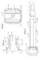
- FIG. 1is a plan view of a probe assembly including a diagnostic and/or therapeutic apparatus and a tubular member in accordance with a preferred embodiment of a present invention.
- FIG. 2is a plan view of the diagnostic and/or therapeutic apparatus illustrated in FIG. 1 .
- FIG. 3is a plan view of the tubular member illustrated in FIG. 1 .
- FIG. 4is a side, partial section view of a portion of the diagnostic and/or therapeutic apparatus handle illustrated in FIGS. 1 and 2.
- FIG. 5is a bottom view of a portion of the probe assembly illustrated in FIG. 1 .
- FIG. 6is a section view taken along line 6 — 6 in FIG. 4 .
- FIG. 7is a plan view of a procedure kit in accordance with preferred embodiment of a present invention.
- the present inventionsmay be in the form of catheter-based probes used within body lumens, chambers or cavities for diagnostic or therapeutic purposes in those instance where access to interior bodily regions is obtained through, for example, the vascular system or alimentary canal and without complex invasive surgical procedures.
- the inventions hereinhave application in the diagnosis and treatment of conditions within the heart.
- the inventions hereinalso have application in the diagnosis or treatment of ailments of the gastrointestinal tract, prostrate, brain, gall bladder, uterus, and other regions of the body.
- some implementations of the inventionsmay encompass hand held surgical devices (or “surgical probes”) with a diagnostic and/or therapeutic structure on the distal end of the probe.
- the diagnostic and/or therapeutic structuremay be placed directly in contact with the targeted tissue area by a physician during a surgical procedure.
- accessmay be obtained by way of a thoracotomy, median sternotomy, or thoracostomy.
- Exemplary surgical probesare disclosed in U.S. Pat. No. 6,142,994.
- Surgical probe devices in accordance with the present inventionspreferably include a handle, a relatively short shaft, and one of the distal expandable/collapsible devices described hereafter in the catheter context.
- the length of the shaftis about 4 inches to about 18 inches. This is relatively short in comparison to the portion of a catheter body that is inserted into the patient (typically from 23 to 55 inches in length) and the additional body portion that remains outside the patient.
- a probe assembly 10in accordance with one embodiment of a present invention includes a diagnostic and/or therapeutic (“DT”) apparatus 12 and a tubular member 14 into which the DT apparatus is inserted.
- the DT apparatus 12includes a handle 16 , a catheter body 18 and a collapsible/expandable device 20 mounted on the distal end of the catheter body, while the tubular member 14 is preferably a sheath having a lumen through which the catheter body and collapsible/expandable device may be advanced.
- the DT apparatus 12 and a tubular member 14are adapted to be removably secured to one another in the manner illustrated for example in FIG. 1 . So arranged, the handle 18 may be used to urge the collapsible/expandable device 20 in and out of the distal end 22 of the tubular member 14 .
- removably securedis used herein to describe situations where the DT apparatus 12 and tubular member 14 may be readily coupled and de-coupled from one another through, for example, an interlocking mechanical connection. Such situations exclude methods of permanently (or “fixedly”) securing elements together, such as chemical bonding, welding and using mechanical fastening devices that are not designed or positioned in a manner that allows them to be readily unfastened by the user.
- the DT apparatus 12 and tubular member 14are removably secured to one another with a luer lock arrangement that consists of a male luer fitting 24 on the DT apparatus and a female luer fitting 26 on the tubular member.
- the male luer fitting 24includes a pair of external detents 28
- the female luer fitting 26includes corresponding internal threads (not shown).
- the detents 28 and threadsare configured such that the male luer fitting 24 and female luer fitting 26 can be locked with one-half of a turn.
- other devices that will removably secure the DT apparatus 12 to the tubular member 14may also be used.
- a tapered, friction fit arrangementmay be employed.
- the handle 16consists of an inner handle member 30 and an outer handle member 32 , each of which is formed from molded plastic or another suitable material.
- the outer handle member 32is slidably supported on the inner handle member 30 by proximal and distal base portions 34 and 36 such that the inner and outer handle members may be moved longitudinally relative to one another.
- the inner handle member 30is removably secured to the tubular member 14 by way of the luer fittings 24 and 26 , while the outer handle member 32 is fixedly secured to the catheter body 18 in the manner described below.
- the inner handle member 30is an open structure that includes a pair of side members 44 and 46 which define an open region 48 therebetween, while the outer handle member 32 includes a post 50 that slides distally and proximally between the side members.
- the proximal end of the catheter body 18is fixedly secured to the post 50 .
- the post 50will include an aperture into which the proximal end of the catheter 18 is inserted and either press-fit or glued in place.
- handlesmay be employed so long as the handle is capable of causing relative movement between the DT apparatus 12 and tubular member 14 .
- the exemplary handle 16may be modified such that the inner handle member 30 is fixedly secured to the catheter body 18 and the outer handle member 32 is removably secured to the tubular member 14 .
- the outer member distal base portion 36would be extended beyond the distal end of the inner handle member 30 .
- a piston and cylinder arrangementsuch as that found in the Polaris® handle manufactured by EP Technologies, Inc. in San Jose, Calif., may also be employed.
- the DT apparatus 12would be fixedly secured to the Polaris® handle cylinder and tubular member 14 would be removably secured to the piston. This arrangement may also be reversed if desired.
- Handlesthat include a handle body and a rotating control device mounted thereon are also contemplated.
- the DT apparatus 12could be operably connected to the rotating control device and tubular member 14 could be removably secured to the handle body.
- the catheter bodyis preferably a tubular element formed from a flexible biocompatible thermoplastic material such as braided or unbraided Pebax® (polyether block emide), polyethylene, or polyurethane, and is about 6 French to about 9 French in diameter.
- the catheter body 12may, if desired, have a two part construction consisting of a relatively short flexible distal member (formed from unbraided Pebax®) that can bend with the distal portion of the tubular member 14 and a longer less flexible proximal member (formed from braided Pebax®).
- a guide coilmay be used in place of the plastic tubing.
- the collapsible/expandable device 20is a mapping and/or coagulation basket.
- Such basketstypically include two to eight electrode supporting splines 52 and one to eight electrodes 54 on each spline.
- the exemplary embodimentincludes eight splines 52 with eight electrodes 54 on each spline.
- the splines 52which are preferably made of a resilient, biologically inert material such as Nitinol® metal, flat stainless steel ribbon, stranded stainless steel or silicone rubber, may be arranged either symmetrically or asymmetrically about the longitudinal axis of the basket.
- the splines 52are connected between a base member 56 and an end cap 58 (or solder bead when stainless steel is employed) in a resilient, pretensed, radially expanded condition that will bend and conform to the tissue surface they contact.
- a suitable basket and catheter arrangementis the Constellation® basket catheter manufactured by EP Technologies, Inc. in San Jose, Calif.
- Another exemplary collapsible/expandable deviceis an inflatable microporous structure, such as one of the inflatable structures illustrated in U.S. Pat. Nos. 5,961,513 and 6,099,526, which are incorporated herein by reference.
- the handle 16would have to be modified so as to include a fluid inlet/outlet port when an inflatable microporous structure is used.
- the tubular member 14is preferably a sheath formed from materials such as braided Pebax®, polyethylene, or polyurethane.
- the length and diameterwill vary in accordance with the intended application.
- the lengthis preferably from 60 cm to 110 cm, the outer diameter is preferably from 3 mm to 4 mm and the inner diameter is preferably from 2.5 mm to 3.5 mm.
- the distal portion of the tubular member 14may have a region 60 with a preset curvature formed by heat setting or other suitable techniques.
- the tubular member distal tip 62is preferably softer than the remaining portion of the tubular member 14 to reduce the likelihood of tissue trauma.
- a marker band 64which is formed from a material such as platinum or gold that is visible using fluoroscopic imaging techniques, is positioned near the soft distal tip 62 .
- the exemplary tubular member 14is also provided with a fluid infusion port 66 that allows fluids, such as water or saline for lubrication, to be introduced into the tubular member.
- a luer lock connectionthat can be connected to a syringe is a suitable fluid infusion port.
- the interior region of the female luer fitting 26will include a haemostatic valve (not shown) located proximal to the fluid infusion port 66 .
- An electrical connector 67may be positioned on the handle 16 .
- a suitable connectoris a 64-pin dual edge connector, such as those manufactured by AMP in Erie, Pa.
- a re-usable ribbon cable or other suitable electrical cablewould be connected to the connector 67 and to a conventional electrophysiological mapping system.
- One advantage of the electrical connector 67 and re-usable cable arrangementis cost savings because a permanent cable need not be incorporated into every DT apparatus as, is the case now with many conventional diagnostic and/or therapeutic apparatus.
- the electrical connector 67is preferably mounted on the portion of the handle 16 that is connected to the catheter body 18 so that the wires (not shown) from the electrodes 54 can be easily terminated within the connector.
- the connector 67is mounted on the outer handle member 32 .
- the connector 67could, for example, be positioned on the proximal end of the thumb aperture 38 .
- the exemplary probe assembly 10 illustrated in FIGS. 1-6may be incorporated into an electrophysiological procedure kit 68 .
- the exemplary kit 68includes the DT apparatus 12 and a plurality of tubular members 14 , 70 and 72 .
- the tubular members 70 and 72have different characteristics than tubular member 14 . Such characteristics may include, but are not limited to, flexibility and distal region curvature.
- the DT apparatus and required tubular membersmay be provided in a convenient kit.
- the other tools and devices required for a particular procedure or set of proceduresmay be provided within the kit itself or provided separately.
- the tubular member that is expected to be used in the first procedurewill be pre-coupled with DT apparatus in the manner illustrated in FIG. 7 .
- the physicianwill simply remove the probe assembly from the patient, decouple the DT apparatus from the tubular member, remove the tubular member, introduce the DT apparatus into one of the other tubular members with an introducer sheath, couple the two together, and re-introduce the probe assembly into the patient.
- tubular members 70 and 72are essentially identical to the tubular member 14 but for the distal region curvature.
- the tubular members in the kit 68may, for example, be selected from tubular members having 15, 30, 55, 120 and 140 degree distal region curvatures. The number of tubular members included in the kit 68 will, of course, depend on the procedure.
- the DT apparatus 12 and tubular members 14 , 70 and 72are housed in a sterile package 74 that has a flat rigid bottom portion 76 and a top transparent top cover 78 that provides recesses for the DT apparatus, tubular members, and any other included tools.
- the bottom portion 76may be formed from Tyvek® spun bonded plastic fibers, or other suitable materials, which allow the contents of the package to be sterilized after the tools are sealed within the package.
- the fluid infusion port 66(such as a luer fitting) allows fluids, such as water or saline for lubrication, to be introduced into the tubular members 14 , 70 and 72 .
- the fluidsare typically stored in a drip bag.
- the tubular members 14 , 70 and 72are packaged with pre-attached fluid tubes 80 that can be connected to the drip bags.
- Each fluid tube 80includes a female luer fitting 82 and a stop valve 84 .
Landscapes
- Health & Medical Sciences (AREA)
- Life Sciences & Earth Sciences (AREA)
- Medical Informatics (AREA)
- Biophysics (AREA)
- Pathology (AREA)
- Engineering & Computer Science (AREA)
- Biomedical Technology (AREA)
- Heart & Thoracic Surgery (AREA)
- Physics & Mathematics (AREA)
- Molecular Biology (AREA)
- Surgery (AREA)
- Animal Behavior & Ethology (AREA)
- General Health & Medical Sciences (AREA)
- Public Health (AREA)
- Veterinary Medicine (AREA)
- Physiology (AREA)
- Cardiology (AREA)
- Surgical Instruments (AREA)
Abstract
Description
Claims (27)
Priority Applications (1)
| Application Number | Priority Date | Filing Date | Title |
|---|---|---|---|
| US09/827,611US6647281B2 (en) | 2001-04-06 | 2001-04-06 | Expandable diagnostic or therapeutic apparatus and system for introducing the same into the body |
Applications Claiming Priority (1)
| Application Number | Priority Date | Filing Date | Title |
|---|---|---|---|
| US09/827,611US6647281B2 (en) | 2001-04-06 | 2001-04-06 | Expandable diagnostic or therapeutic apparatus and system for introducing the same into the body |
Publications (2)
| Publication Number | Publication Date |
|---|---|
| US20020147391A1 US20020147391A1 (en) | 2002-10-10 |
| US6647281B2true US6647281B2 (en) | 2003-11-11 |
Family
ID=25249667
Family Applications (1)
| Application Number | Title | Priority Date | Filing Date |
|---|---|---|---|
| US09/827,611Expired - Fee RelatedUS6647281B2 (en) | 2001-04-06 | 2001-04-06 | Expandable diagnostic or therapeutic apparatus and system for introducing the same into the body |
Country Status (1)
| Country | Link |
|---|---|
| US (1) | US6647281B2 (en) |
Cited By (51)
| Publication number | Priority date | Publication date | Assignee | Title |
|---|---|---|---|---|
| US20030236549A1 (en)* | 2000-07-21 | 2003-12-25 | Frank Bonadio | Surgical instrument |
| US20040181136A1 (en)* | 2003-03-12 | 2004-09-16 | Mcdaniel Benjamin D. | Deflectable catheter with hinge |
| US20040181138A1 (en)* | 2003-03-12 | 2004-09-16 | Gerhard Hindricks | Method for treating tissue |
| JP2007534395A (en)* | 2004-04-28 | 2007-11-29 | エルベ エレクトロメディツィン ゲーエムベーハー | Waterjet surgery equipment |
| US9000720B2 (en) | 2010-11-05 | 2015-04-07 | Ethicon Endo-Surgery, Inc. | Medical device packaging with charging interface |
| US8998939B2 (en) | 2010-11-05 | 2015-04-07 | Ethicon Endo-Surgery, Inc. | Surgical instrument with modular end effector |
| US9011427B2 (en) | 2010-11-05 | 2015-04-21 | Ethicon Endo-Surgery, Inc. | Surgical instrument safety glasses |
| US9011471B2 (en) | 2010-11-05 | 2015-04-21 | Ethicon Endo-Surgery, Inc. | Surgical instrument with pivoting coupling to modular shaft and end effector |
| US9017851B2 (en) | 2010-11-05 | 2015-04-28 | Ethicon Endo-Surgery, Inc. | Sterile housing for non-sterile medical device component |
| US9017849B2 (en) | 2010-11-05 | 2015-04-28 | Ethicon Endo-Surgery, Inc. | Power source management for medical device |
| US9039720B2 (en) | 2010-11-05 | 2015-05-26 | Ethicon Endo-Surgery, Inc. | Surgical instrument with ratcheting rotatable shaft |
| US9089338B2 (en) | 2010-11-05 | 2015-07-28 | Ethicon Endo-Surgery, Inc. | Medical device packaging with window for insertion of reusable component |
| WO2015143061A1 (en) | 2014-03-18 | 2015-09-24 | Boston Scientific Scimed, Inc. | Electrophysiology system |
| US9161803B2 (en) | 2010-11-05 | 2015-10-20 | Ethicon Endo-Surgery, Inc. | Motor driven electrosurgical device with mechanical and electrical feedback |
| US9247986B2 (en) | 2010-11-05 | 2016-02-02 | Ethicon Endo-Surgery, Llc | Surgical instrument with ultrasonic transducer having integral switches |
| US9370329B2 (en) | 2012-09-18 | 2016-06-21 | Boston Scientific Scimed, Inc. | Map and ablate closed-loop cooled ablation catheter |
| US9375255B2 (en) | 2010-11-05 | 2016-06-28 | Ethicon Endo-Surgery, Llc | Surgical instrument handpiece with resiliently biased coupling to modular shaft and end effector |
| US9381058B2 (en) | 2010-11-05 | 2016-07-05 | Ethicon Endo-Surgery, Llc | Recharge system for medical devices |
| US9393072B2 (en) | 2009-06-30 | 2016-07-19 | Boston Scientific Scimed, Inc. | Map and ablate open irrigated hybrid catheter |
| US9421062B2 (en) | 2010-11-05 | 2016-08-23 | Ethicon Endo-Surgery, Llc | Surgical instrument shaft with resiliently biased coupling to handpiece |
| US9463064B2 (en) | 2011-09-14 | 2016-10-11 | Boston Scientific Scimed Inc. | Ablation device with multiple ablation modes |
| US9504399B2 (en) | 2011-04-22 | 2016-11-29 | Topera, Inc. | Basket style cardiac mapping catheter having a flexible electrode assembly for sensing monophasic action potentials |
| US9526921B2 (en) | 2010-11-05 | 2016-12-27 | Ethicon Endo-Surgery, Llc | User feedback through end effector of surgical instrument |
| US9532725B2 (en) | 2014-03-07 | 2017-01-03 | Boston Scientific Scimed Inc. | Medical devices for mapping cardiac tissue |
| WO2017004093A1 (en) | 2015-06-29 | 2017-01-05 | Boston Scientific Scimed Inc. | Open-irrigated ablation catheter |
| US9603659B2 (en) | 2011-09-14 | 2017-03-28 | Boston Scientific Scimed Inc. | Ablation device with ionically conductive balloon |
| US9649150B2 (en) | 2010-11-05 | 2017-05-16 | Ethicon Endo-Surgery, Llc | Selective activation of electronic components in medical device |
| WO2017087845A1 (en) | 2015-11-20 | 2017-05-26 | Boston Scientific Scimed Inc. | Tissue contact sensing vector |
| US9687167B2 (en) | 2014-03-11 | 2017-06-27 | Boston Scientific Scimed, Inc. | Medical devices for mapping cardiac tissue |
| US9717554B2 (en) | 2012-03-26 | 2017-08-01 | Biosense Webster (Israel) Ltd. | Catheter with composite construction |
| US9730600B2 (en) | 2013-10-31 | 2017-08-15 | Boston Scientific Scimed, Inc. | Medical device for high resolution mapping using localized matching |
| US9743854B2 (en) | 2014-12-18 | 2017-08-29 | Boston Scientific Scimed, Inc. | Real-time morphology analysis for lesion assessment |
| US9757191B2 (en) | 2012-01-10 | 2017-09-12 | Boston Scientific Scimed, Inc. | Electrophysiology system and methods |
| US9782214B2 (en) | 2010-11-05 | 2017-10-10 | Ethicon Llc | Surgical instrument with sensor and powered control |
| US9782215B2 (en) | 2010-11-05 | 2017-10-10 | Ethicon Endo-Surgery, Llc | Surgical instrument with ultrasonic transducer having integral switches |
| US10076258B2 (en) | 2013-11-01 | 2018-09-18 | Boston Scientific Scimed, Inc. | Cardiac mapping using latency interpolation |
| US10085792B2 (en) | 2010-11-05 | 2018-10-02 | Ethicon Llc | Surgical instrument with motorized attachment feature |
| US10136938B2 (en) | 2014-10-29 | 2018-11-27 | Ethicon Llc | Electrosurgical instrument with sensor |
| US10420605B2 (en) | 2012-01-31 | 2019-09-24 | Koninklijke Philips N.V. | Ablation probe with fluid-based acoustic coupling for ultrasonic tissue imaging |
| US10441295B2 (en) | 2013-10-15 | 2019-10-15 | Stryker Corporation | Device for creating a void space in a living tissue, the device including a handle with a control knob that can be set regardless of the orientation of the handle |
| US10524684B2 (en) | 2014-10-13 | 2020-01-07 | Boston Scientific Scimed Inc | Tissue diagnosis and treatment using mini-electrodes |
| US10537380B2 (en) | 2010-11-05 | 2020-01-21 | Ethicon Llc | Surgical instrument with charging station and wireless communication |
| US10603105B2 (en) | 2014-10-24 | 2020-03-31 | Boston Scientific Scimed Inc | Medical devices with a flexible electrode assembly coupled to an ablation tip |
| US10639099B2 (en) | 2012-05-25 | 2020-05-05 | Biosense Webster (Israel), Ltd. | Catheter having a distal section with spring sections for biased deflection |
| US10660695B2 (en) | 2010-11-05 | 2020-05-26 | Ethicon Llc | Sterile medical instrument charging device |
| US10881448B2 (en) | 2010-11-05 | 2021-01-05 | Ethicon Llc | Cam driven coupling between ultrasonic transducer and waveguide in surgical instrument |
| US10959769B2 (en) | 2010-11-05 | 2021-03-30 | Ethicon Llc | Surgical instrument with slip ring assembly to power ultrasonic transducer |
| US10973563B2 (en) | 2010-11-05 | 2021-04-13 | Ethicon Llc | Surgical instrument with charging devices |
| US11471650B2 (en) | 2019-09-20 | 2022-10-18 | Biosense Webster (Israel) Ltd. | Mechanism for manipulating a puller wire |
| US11684416B2 (en) | 2009-02-11 | 2023-06-27 | Boston Scientific Scimed, Inc. | Insulated ablation catheter devices and methods of use |
| US11849986B2 (en) | 2019-04-24 | 2023-12-26 | Stryker Corporation | Systems and methods for off-axis augmentation of a vertebral body |
Families Citing this family (13)
| Publication number | Priority date | Publication date | Assignee | Title |
|---|---|---|---|---|
| WO2006052940A2 (en) | 2004-11-05 | 2006-05-18 | Asthmatx, Inc. | Medical device with procedure improvement features |
| US7949407B2 (en) | 2004-11-05 | 2011-05-24 | Asthmatx, Inc. | Energy delivery devices and methods |
| US20070093802A1 (en)* | 2005-10-21 | 2007-04-26 | Danek Christopher J | Energy delivery devices and methods |
| US7931647B2 (en) | 2006-10-20 | 2011-04-26 | Asthmatx, Inc. | Method of delivering energy to a lung airway using markers |
| US8235983B2 (en) | 2007-07-12 | 2012-08-07 | Asthmatx, Inc. | Systems and methods for delivering energy to passageways in a patient |
| WO2012037341A1 (en)* | 2010-09-15 | 2012-03-22 | The United States Of America, As Represented By The Secretary, National Institutes Of Health | Devices for transcatheter cerclage annuloplasty |
| US9597143B2 (en)* | 2010-11-05 | 2017-03-21 | Ethicon Endo-Surgery, Llc | Sterile medical instrument charging device |
| US9814618B2 (en) | 2013-06-06 | 2017-11-14 | Boston Scientific Scimed, Inc. | Devices for delivering energy and related methods of use |
| US11039923B2 (en) | 2016-05-06 | 2021-06-22 | Transmural Systems Llc | Annuloplasty procedures, related devices and methods |
| US11007059B2 (en) | 2016-05-06 | 2021-05-18 | Transmural Systems Llc | Annuloplasty procedures, related devices and methods |
| WO2019046205A1 (en) | 2017-08-26 | 2019-03-07 | Macdonald, Stuart | Cardiac annuloplasty and pacing procedures, related devices and methods |
| US11980545B2 (en) | 2016-05-06 | 2024-05-14 | Transmural Systems Llc | Annuloplasty procedures, related devices and methods |
| EP4034215A1 (en)* | 2019-09-23 | 2022-08-03 | Cook Medical Technologies, LLC | Strain relief member and method of manufacturing the same |
Citations (10)
| Publication number | Priority date | Publication date | Assignee | Title |
|---|---|---|---|---|
| US5309910A (en) | 1992-09-25 | 1994-05-10 | Ep Technologies, Inc. | Cardiac mapping and ablation systems |
| US5376094A (en)* | 1993-08-19 | 1994-12-27 | Boston Scientific Corporation | Improved actuating handle with pulley system for providing mechanical advantage to a surgical working element |
| US5741286A (en)* | 1996-06-07 | 1998-04-21 | Symbiosis Corporation | Laparoscopic instrument kit including a plurality of rigid tubes |
| WO1998026724A1 (en) | 1996-12-19 | 1998-06-25 | Ep Technologies, Inc. | Branched structures for supporting multiple electrode elements |
| US5961513A (en) | 1996-01-19 | 1999-10-05 | Ep Technologies, Inc. | Tissue heating and ablation systems and methods using porous electrode structures |
| US6099526A (en) | 1996-01-19 | 2000-08-08 | Ep Technologies, Inc. | Electrode structure including hydrophilic material |
| US6143021A (en) | 1998-07-10 | 2000-11-07 | American Medical Systems, Inc. | Stent placement instrument and method of assembly |
| US6142994A (en) | 1994-10-07 | 2000-11-07 | Ep Technologies, Inc. | Surgical method and apparatus for positioning a diagnostic a therapeutic element within the body |
| US6197003B1 (en) | 1997-08-15 | 2001-03-06 | University Of Iowa Research Foundation | Catheter advancing single-handed soft passer |
| US6203525B1 (en) | 1996-12-19 | 2001-03-20 | Ep Technologies, Inc. | Catheterdistal assembly with pull wires |
- 2001
- 2001-04-06USUS09/827,611patent/US6647281B2/ennot_activeExpired - Fee Related
Patent Citations (10)
| Publication number | Priority date | Publication date | Assignee | Title |
|---|---|---|---|---|
| US5309910A (en) | 1992-09-25 | 1994-05-10 | Ep Technologies, Inc. | Cardiac mapping and ablation systems |
| US5376094A (en)* | 1993-08-19 | 1994-12-27 | Boston Scientific Corporation | Improved actuating handle with pulley system for providing mechanical advantage to a surgical working element |
| US6142994A (en) | 1994-10-07 | 2000-11-07 | Ep Technologies, Inc. | Surgical method and apparatus for positioning a diagnostic a therapeutic element within the body |
| US5961513A (en) | 1996-01-19 | 1999-10-05 | Ep Technologies, Inc. | Tissue heating and ablation systems and methods using porous electrode structures |
| US6099526A (en) | 1996-01-19 | 2000-08-08 | Ep Technologies, Inc. | Electrode structure including hydrophilic material |
| US5741286A (en)* | 1996-06-07 | 1998-04-21 | Symbiosis Corporation | Laparoscopic instrument kit including a plurality of rigid tubes |
| WO1998026724A1 (en) | 1996-12-19 | 1998-06-25 | Ep Technologies, Inc. | Branched structures for supporting multiple electrode elements |
| US6203525B1 (en) | 1996-12-19 | 2001-03-20 | Ep Technologies, Inc. | Catheterdistal assembly with pull wires |
| US6197003B1 (en) | 1997-08-15 | 2001-03-06 | University Of Iowa Research Foundation | Catheter advancing single-handed soft passer |
| US6143021A (en) | 1998-07-10 | 2000-11-07 | American Medical Systems, Inc. | Stent placement instrument and method of assembly |
Non-Patent Citations (1)
| Title |
|---|
| "Electrophysiology Catheters", EP Medsystems Ind., 1999.* |
Cited By (85)
| Publication number | Priority date | Publication date | Assignee | Title |
|---|---|---|---|---|
| US8157817B2 (en) | 2000-07-21 | 2012-04-17 | Atropos Limited | Surgical instrument |
| US20030236549A1 (en)* | 2000-07-21 | 2003-12-25 | Frank Bonadio | Surgical instrument |
| US8764743B2 (en) | 2003-03-12 | 2014-07-01 | Biosense Webster, Inc. | Deflectable catheter with hinge |
| US7276062B2 (en)* | 2003-03-12 | 2007-10-02 | Biosence Webster, Inc. | Deflectable catheter with hinge |
| US20080086047A1 (en)* | 2003-03-12 | 2008-04-10 | Biosense Webster, Inc. | Deflectable catheter with hinge |
| US20040181138A1 (en)* | 2003-03-12 | 2004-09-16 | Gerhard Hindricks | Method for treating tissue |
| US8256428B2 (en) | 2003-03-12 | 2012-09-04 | Biosense Webster, Inc. | Method for treating tissue |
| US10814100B2 (en) | 2003-03-12 | 2020-10-27 | Biosense Webster, Inc. | Deflectable catheter with hinge |
| US10183150B2 (en) | 2003-03-12 | 2019-01-22 | Biosense Webster, Inc. | Deflectable catheter with hinge |
| US20040181136A1 (en)* | 2003-03-12 | 2004-09-16 | Mcdaniel Benjamin D. | Deflectable catheter with hinge |
| US9636482B2 (en) | 2003-03-12 | 2017-05-02 | Biosense Webster, Inc. | Deflectable catheter with hinge |
| JP2007534395A (en)* | 2004-04-28 | 2007-11-29 | エルベ エレクトロメディツィン ゲーエムベーハー | Waterjet surgery equipment |
| US20080243157A1 (en)* | 2004-04-28 | 2008-10-02 | Erbe Elektromedizin Gmbh | Applicator For Water-Jet Surgery |
| US11684416B2 (en) | 2009-02-11 | 2023-06-27 | Boston Scientific Scimed, Inc. | Insulated ablation catheter devices and methods of use |
| US9393072B2 (en) | 2009-06-30 | 2016-07-19 | Boston Scientific Scimed, Inc. | Map and ablate open irrigated hybrid catheter |
| US9526921B2 (en) | 2010-11-05 | 2016-12-27 | Ethicon Endo-Surgery, Llc | User feedback through end effector of surgical instrument |
| US9011471B2 (en) | 2010-11-05 | 2015-04-21 | Ethicon Endo-Surgery, Inc. | Surgical instrument with pivoting coupling to modular shaft and end effector |
| US9072523B2 (en) | 2010-11-05 | 2015-07-07 | Ethicon Endo-Surgery, Inc. | Medical device with feature for sterile acceptance of non-sterile reusable component |
| US9089338B2 (en) | 2010-11-05 | 2015-07-28 | Ethicon Endo-Surgery, Inc. | Medical device packaging with window for insertion of reusable component |
| US9095346B2 (en) | 2010-11-05 | 2015-08-04 | Ethicon Endo-Surgery, Inc. | Medical device usage data processing |
| US10973563B2 (en) | 2010-11-05 | 2021-04-13 | Ethicon Llc | Surgical instrument with charging devices |
| US9161803B2 (en) | 2010-11-05 | 2015-10-20 | Ethicon Endo-Surgery, Inc. | Motor driven electrosurgical device with mechanical and electrical feedback |
| US9192428B2 (en) | 2010-11-05 | 2015-11-24 | Ethicon Endo-Surgery, Inc. | Surgical instrument with modular clamp pad |
| US9247986B2 (en) | 2010-11-05 | 2016-02-02 | Ethicon Endo-Surgery, Llc | Surgical instrument with ultrasonic transducer having integral switches |
| US9308009B2 (en) | 2010-11-05 | 2016-04-12 | Ethicon Endo-Surgery, Llc | Surgical instrument with modular shaft and transducer |
| US9364279B2 (en) | 2010-11-05 | 2016-06-14 | Ethicon Endo-Surgery, Llc | User feedback through handpiece of surgical instrument |
| US10959769B2 (en) | 2010-11-05 | 2021-03-30 | Ethicon Llc | Surgical instrument with slip ring assembly to power ultrasonic transducer |
| US9375255B2 (en) | 2010-11-05 | 2016-06-28 | Ethicon Endo-Surgery, Llc | Surgical instrument handpiece with resiliently biased coupling to modular shaft and end effector |
| US9381058B2 (en) | 2010-11-05 | 2016-07-05 | Ethicon Endo-Surgery, Llc | Recharge system for medical devices |
| US9017849B2 (en) | 2010-11-05 | 2015-04-28 | Ethicon Endo-Surgery, Inc. | Power source management for medical device |
| US9421062B2 (en) | 2010-11-05 | 2016-08-23 | Ethicon Endo-Surgery, Llc | Surgical instrument shaft with resiliently biased coupling to handpiece |
| US10945783B2 (en) | 2010-11-05 | 2021-03-16 | Ethicon Llc | Surgical instrument with modular shaft and end effector |
| US10881448B2 (en) | 2010-11-05 | 2021-01-05 | Ethicon Llc | Cam driven coupling between ultrasonic transducer and waveguide in surgical instrument |
| US9510895B2 (en) | 2010-11-05 | 2016-12-06 | Ethicon Endo-Surgery, Llc | Surgical instrument with modular shaft and end effector |
| US9000720B2 (en) | 2010-11-05 | 2015-04-07 | Ethicon Endo-Surgery, Inc. | Medical device packaging with charging interface |
| US10660695B2 (en) | 2010-11-05 | 2020-05-26 | Ethicon Llc | Sterile medical instrument charging device |
| US11389228B2 (en) | 2010-11-05 | 2022-07-19 | Cilag Gmbh International | Surgical instrument with sensor and powered control |
| US8998939B2 (en) | 2010-11-05 | 2015-04-07 | Ethicon Endo-Surgery, Inc. | Surgical instrument with modular end effector |
| US10537380B2 (en) | 2010-11-05 | 2020-01-21 | Ethicon Llc | Surgical instrument with charging station and wireless communication |
| US9017851B2 (en) | 2010-11-05 | 2015-04-28 | Ethicon Endo-Surgery, Inc. | Sterile housing for non-sterile medical device component |
| US9649150B2 (en) | 2010-11-05 | 2017-05-16 | Ethicon Endo-Surgery, Llc | Selective activation of electronic components in medical device |
| US11925335B2 (en) | 2010-11-05 | 2024-03-12 | Cilag Gmbh International | Surgical instrument with slip ring assembly to power ultrasonic transducer |
| US9039720B2 (en) | 2010-11-05 | 2015-05-26 | Ethicon Endo-Surgery, Inc. | Surgical instrument with ratcheting rotatable shaft |
| US11690605B2 (en) | 2010-11-05 | 2023-07-04 | Cilag Gmbh International | Surgical instrument with charging station and wireless communication |
| US10376304B2 (en) | 2010-11-05 | 2019-08-13 | Ethicon Llc | Surgical instrument with modular shaft and end effector |
| US11744635B2 (en) | 2010-11-05 | 2023-09-05 | Cilag Gmbh International | Sterile medical instrument charging device |
| US9011427B2 (en) | 2010-11-05 | 2015-04-21 | Ethicon Endo-Surgery, Inc. | Surgical instrument safety glasses |
| US9782214B2 (en) | 2010-11-05 | 2017-10-10 | Ethicon Llc | Surgical instrument with sensor and powered control |
| US9782215B2 (en) | 2010-11-05 | 2017-10-10 | Ethicon Endo-Surgery, Llc | Surgical instrument with ultrasonic transducer having integral switches |
| US10143513B2 (en) | 2010-11-05 | 2018-12-04 | Ethicon Llc | Gear driven coupling between ultrasonic transducer and waveguide in surgical instrument |
| US10085792B2 (en) | 2010-11-05 | 2018-10-02 | Ethicon Llc | Surgical instrument with motorized attachment feature |
| US9560982B2 (en) | 2011-04-22 | 2017-02-07 | Topera, Inc. | Methods for detection of cardiac rhythm disorders using basket style cardiac mapping catheter |
| US9895072B2 (en) | 2011-04-22 | 2018-02-20 | Topera, Inc. | Basket style cardiac mapping catheter having an atraumatic, metallic two-part distal tip for detection of cardiac rhythm disorders |
| US10244960B2 (en) | 2011-04-22 | 2019-04-02 | Topera, Inc. | Basket style cardiac mapping catheter having spline bends for detection of cardiac rhythm disorders |
| US9504399B2 (en) | 2011-04-22 | 2016-11-29 | Topera, Inc. | Basket style cardiac mapping catheter having a flexible electrode assembly for sensing monophasic action potentials |
| US9463064B2 (en) | 2011-09-14 | 2016-10-11 | Boston Scientific Scimed Inc. | Ablation device with multiple ablation modes |
| US9603659B2 (en) | 2011-09-14 | 2017-03-28 | Boston Scientific Scimed Inc. | Ablation device with ionically conductive balloon |
| US9757191B2 (en) | 2012-01-10 | 2017-09-12 | Boston Scientific Scimed, Inc. | Electrophysiology system and methods |
| US10420605B2 (en) | 2012-01-31 | 2019-09-24 | Koninklijke Philips N.V. | Ablation probe with fluid-based acoustic coupling for ultrasonic tissue imaging |
| US10512503B2 (en) | 2012-03-26 | 2019-12-24 | Biosense Webster (Israel) Ltd. | Catheter with composite construction |
| US9717554B2 (en) | 2012-03-26 | 2017-08-01 | Biosense Webster (Israel) Ltd. | Catheter with composite construction |
| US11737816B2 (en) | 2012-03-26 | 2023-08-29 | Biosense Webster (Israel) Ltd. | Catheter with composite construction |
| US11931100B2 (en) | 2012-03-26 | 2024-03-19 | Biosense Webster (Israel) Ltd. | Catheter with composite construction |
| US10639099B2 (en) | 2012-05-25 | 2020-05-05 | Biosense Webster (Israel), Ltd. | Catheter having a distal section with spring sections for biased deflection |
| US9370329B2 (en) | 2012-09-18 | 2016-06-21 | Boston Scientific Scimed, Inc. | Map and ablate closed-loop cooled ablation catheter |
| US11259818B2 (en) | 2013-10-15 | 2022-03-01 | Stryker Corporation | Methods for creating a void within a bone |
| US10441295B2 (en) | 2013-10-15 | 2019-10-15 | Stryker Corporation | Device for creating a void space in a living tissue, the device including a handle with a control knob that can be set regardless of the orientation of the handle |
| US12396738B2 (en) | 2013-10-15 | 2025-08-26 | Stryker Corporation | Device including steering cables for creating a cavity or a channel in bone |
| US9730600B2 (en) | 2013-10-31 | 2017-08-15 | Boston Scientific Scimed, Inc. | Medical device for high resolution mapping using localized matching |
| US10076258B2 (en) | 2013-11-01 | 2018-09-18 | Boston Scientific Scimed, Inc. | Cardiac mapping using latency interpolation |
| US9532725B2 (en) | 2014-03-07 | 2017-01-03 | Boston Scientific Scimed Inc. | Medical devices for mapping cardiac tissue |
| US9687167B2 (en) | 2014-03-11 | 2017-06-27 | Boston Scientific Scimed, Inc. | Medical devices for mapping cardiac tissue |
| WO2015143061A1 (en) | 2014-03-18 | 2015-09-24 | Boston Scientific Scimed, Inc. | Electrophysiology system |
| US11589768B2 (en) | 2014-10-13 | 2023-02-28 | Boston Scientific Scimed Inc. | Tissue diagnosis and treatment using mini-electrodes |
| US10524684B2 (en) | 2014-10-13 | 2020-01-07 | Boston Scientific Scimed Inc | Tissue diagnosis and treatment using mini-electrodes |
| US10603105B2 (en) | 2014-10-24 | 2020-03-31 | Boston Scientific Scimed Inc | Medical devices with a flexible electrode assembly coupled to an ablation tip |
| US10136938B2 (en) | 2014-10-29 | 2018-11-27 | Ethicon Llc | Electrosurgical instrument with sensor |
| US9743854B2 (en) | 2014-12-18 | 2017-08-29 | Boston Scientific Scimed, Inc. | Real-time morphology analysis for lesion assessment |
| WO2017004093A1 (en) | 2015-06-29 | 2017-01-05 | Boston Scientific Scimed Inc. | Open-irrigated ablation catheter |
| WO2017087845A1 (en) | 2015-11-20 | 2017-05-26 | Boston Scientific Scimed Inc. | Tissue contact sensing vector |
| US10575900B2 (en) | 2015-11-20 | 2020-03-03 | Boston Scientific Scimed Inc | Tissue contact sensing vector |
| US11849986B2 (en) | 2019-04-24 | 2023-12-26 | Stryker Corporation | Systems and methods for off-axis augmentation of a vertebral body |
| US12279799B2 (en) | 2019-04-24 | 2025-04-22 | Stryker Corporation | Systems and methods for off-axis treatment of a vertebral body |
| US11964115B2 (en) | 2019-09-20 | 2024-04-23 | Biosense Webster (Israel) Ltd. | Mechanism for manipulating a puller wire |
| US11471650B2 (en) | 2019-09-20 | 2022-10-18 | Biosense Webster (Israel) Ltd. | Mechanism for manipulating a puller wire |
Also Published As
| Publication number | Publication date |
|---|---|
| US20020147391A1 (en) | 2002-10-10 |
Similar Documents
| Publication | Publication Date | Title |
|---|---|---|
| US6647281B2 (en) | Expandable diagnostic or therapeutic apparatus and system for introducing the same into the body | |
| JP6869707B2 (en) | Basket catheter with improved seal | |
| JP3992734B2 (en) | Intravascular system to stop the heart | |
| JP6457100B2 (en) | System for minimally invasive gastrointestinal surgery | |
| JP5102033B2 (en) | Expandable transseptal sheath | |
| US6605055B1 (en) | Balloon catheter with irrigation sheath | |
| US9827404B2 (en) | Expandable trans-septal sheath | |
| US8900214B2 (en) | Expandable trans-septal sheath | |
| US20070299403A1 (en) | Directional introducer | |
| US20070167876A1 (en) | Occluding guidewire and methods | |
| US7618410B2 (en) | Devices and methods for access through a tissue wall | |
| US20080004597A1 (en) | Methods and devices for endocardiac access | |
| JP3804351B2 (en) | Balloon catheter | |
| JPH04500464A (en) | Lymph access catheters and access methods | |
| US20190255292A1 (en) | Deflectable sheath with inflatable balloon | |
| WO2008143740A2 (en) | Methods and devices for endocardiac access | |
| WO2011102988A1 (en) | Anatomic needle system | |
| WO2001019441A1 (en) | Multipurpose medical device | |
| US20040087935A1 (en) | Electrophysiological probes having tissue insulation and /or heating device cooling apparatus | |
| US20230226335A1 (en) | Access device | |
| JP7604747B2 (en) | Endoscopic system for energy delivery - Patents.com | |
| JP3638304B2 (en) | Intravascular catheter | |
| CN223311516U (en) | guiding catheter | |
| JP2004216189A (en) | Balloon catheter guidewire assembly | |
| AU2007200672A1 (en) | Endovascular system for arresting the heart |
Legal Events
| Date | Code | Title | Description |
|---|---|---|---|
| AS | Assignment | Owner name:SCIMED LIFE SYSTEMS, INC., MINNESOTA Free format text:ASSIGNMENT OF ASSIGNORS INTEREST;ASSIGNOR:MORENCY, STEVEN;REEL/FRAME:011721/0646 Effective date:20010405 | |
| FEPP | Fee payment procedure | Free format text:PAYOR NUMBER ASSIGNED (ORIGINAL EVENT CODE: ASPN); ENTITY STATUS OF PATENT OWNER: LARGE ENTITY | |
| AS | Assignment | Owner name:BOSTON SCIENTIFIC SCIMED, INC., MINNESOTA Free format text:CHANGE OF NAME;ASSIGNOR:SCIMED LIFE SYSTEMS, INC.;REEL/FRAME:018505/0868 Effective date:20050101 Owner name:BOSTON SCIENTIFIC SCIMED, INC.,MINNESOTA Free format text:CHANGE OF NAME;ASSIGNOR:SCIMED LIFE SYSTEMS, INC.;REEL/FRAME:018505/0868 Effective date:20050101 | |
| FPAY | Fee payment | Year of fee payment:4 | |
| FPAY | Fee payment | Year of fee payment:8 | |
| REMI | Maintenance fee reminder mailed | ||
| LAPS | Lapse for failure to pay maintenance fees | ||
| STCH | Information on status: patent discontinuation | Free format text:PATENT EXPIRED DUE TO NONPAYMENT OF MAINTENANCE FEES UNDER 37 CFR 1.362 | |
| FP | Lapsed due to failure to pay maintenance fee | Effective date:20151111 |