US6647152B2 - Method and system for contouring reduction - Google Patents
Method and system for contouring reductionDownload PDFInfo
- Publication number
- US6647152B2 US6647152B2US10/056,595US5659502AUS6647152B2US 6647152 B2US6647152 B2US 6647152B2US 5659502 AUS5659502 AUS 5659502AUS 6647152 B2US6647152 B2US 6647152B2
- Authority
- US
- United States
- Prior art keywords
- pixel
- span
- identified
- video signal
- pixels
- Prior art date
- Legal status (The legal status is an assumption and is not a legal conclusion. Google has not performed a legal analysis and makes no representation as to the accuracy of the status listed.)
- Expired - Lifetime, expires
Links
Images


Classifications
- G—PHYSICS
- G06—COMPUTING OR CALCULATING; COUNTING
- G06T—IMAGE DATA PROCESSING OR GENERATION, IN GENERAL
- G06T5/00—Image enhancement or restoration
- G06T5/70—Denoising; Smoothing
- G—PHYSICS
- G06—COMPUTING OR CALCULATING; COUNTING
- G06V—IMAGE OR VIDEO RECOGNITION OR UNDERSTANDING
- G06V10/00—Arrangements for image or video recognition or understanding
- G06V10/20—Image preprocessing
- G06V10/30—Noise filtering
- G—PHYSICS
- G06—COMPUTING OR CALCULATING; COUNTING
- G06V—IMAGE OR VIDEO RECOGNITION OR UNDERSTANDING
- G06V10/00—Arrangements for image or video recognition or understanding
- G06V10/20—Image preprocessing
- G06V10/34—Smoothing or thinning of the pattern; Morphological operations; Skeletonisation
- G—PHYSICS
- G06—COMPUTING OR CALCULATING; COUNTING
- G06T—IMAGE DATA PROCESSING OR GENERATION, IN GENERAL
- G06T2207/00—Indexing scheme for image analysis or image enhancement
- G06T2207/10—Image acquisition modality
- G06T2207/10016—Video; Image sequence
Definitions
- the present inventionrelates to the field of image display systems, and more particularly, to methods and systems for reducing contouring artifacts in image display systems.
- All conventional digital video signalsare quantized during various video-processing steps.
- analog to digital conversion and certain compression techniquesinvolve quantization.
- quantizationtends to cause a visual artifact known as contouring in regions of the picture with very low intensity gradients. Contouring occurs when the quantization of an image signal causes contours to appear in an output image that do not exist in the input image. More specifically, when an input signal is quantized a smooth image gradient may be transformed into several large blocks of adjacent pixels, wherein each pixel in a block is assigned an identical image signal value.
- the present inventionis directed to overcoming this drawback.
- the present inventionis directed towards detecting contouring artifacts in a received video signal and removing the detected artifacts by dithering, by adding least significant bits to selected pixels in the video signal, or by utilizing unused states.
- FIG. 1is a block diagram of an exemplary home entertainment system configured to support the present invention
- FIG. 2is a flowchart of a preferred contouring detection test of the present invention
- FIG. 3is a flowchart of an alternative contouring detection test of the present invention.
- FIG. 4is a flowchart of a contouring reduction technique of the present invention.
- FIG. 5is a flowchart of an alternative contouring reduction technique of the present invention.
- FIG. 6is a flowchart of another alternative contouring reduction technique of the present invention.
- FIG. 7is a graph illustrating an exemplary sequence of input pixel component values
- FIG. 8is a graphical comparison of the input pixel component values of FIG. 7 and output pixel component values generated by the contouring reduction process of FIG. 5;
- FIG. 9is a graphical comparison of the input pixel component values of FIG. 7 and output pixel component values generated by the contouring reduction process of FIG. 4;
- FIG. 10is a graph illustrating another exemplary sequence of input pixel component values.
- FIG. 11is a graphical comparison of the input pixel component values of FIG. 10 and output pixel component values generated by the contouring reduction process of FIG. 6 .
- the video receiver systemincludes an antenna 10 and input processor 15 for receiving and digitizing a broadcast carrier modulated with signals carrying audio, video, and associated data, a demodulator 20 for receiving and demodulating the digital output signal from input processor 15 , and a decoder 30 outputting a signal that is trellis decoded, mapped into byte length data segments, de-interleaved, and Reed-Solomon error corrected.
- the corrected output data from decoder unit 30is in the form of an MPEG compatible transport data stream containing program representative multiplexed audio, video, and data components.
- the video receiver systemfurther includes a modem 80 that may be connected, via telephone lines, to a server 83 or connection service 87 such that data in various formats (e.g., MPEG, HTML, and/or JAVA) can be received by the video receiver system over the telephone lines.
- a modem 80may be connected, via telephone lines, to a server 83 or connection service 87 such that data in various formats (e.g., MPEG, HTML, and/or JAVA) can be received by the video receiver system over the telephone lines.
- a processor 25processes the data output from decoder 30 and/or modem 80 such that the processed data can be displayed on a display unit 75 or stored on a storage medium 105 in accordance with requests input by a user via a remote control unit 125 . More specifically, processor 25 includes a controller 115 that interprets requests received from remote control unit 125 via remote unit interface 120 and appropriately configures the elements of processor 25 to carry out user requests (e.g., channel, website, and/or on-screen display (OSD)). In one exemplary mode, controller 115 configures the elements of processor 25 to provide MPEG decoded data and an OSD for display on display unit 75 .
- OSDon-screen display
- controller 115configures the elements of processor 25 to provide an MPEG compatible data stream for storage on storage medium 105 via storage device 90 and store interface 95 .
- controller 115configures the elements of processor 25 for other communication modes, such as for receiving bidirectional (e.g. Internet) communications via server 83 or connection service 87 .
- Processor 25includes a decode PID selection unit 45 that identifies and routes selected packets in the transport stream from decoder 30 to transport decoder 55 .
- the transport stream from decoder 30is demultiplexed into audio, video, and data components by transport decoder 55 and is further processed by the other elements of processor 25 , as described in further detail below.
- the transport stream provided to processor 25comprises data packets containing program channel data, ancillary system timing information, and program specific information such as program content rating, program aspect ratio, and program guide information.
- Transport decoder 55directs the ancillary information packets to controller 115 which parses, collates, and assembles the ancillary information into hierarchically arranged tables. Individual data packets comprising the user selected program channel are identified and assembled using the assembled program specific information.
- the system timing informationcontains a time reference indicator and associated correction data (e.g. a daylight savings time indicator and offset information adjusting for time drift, leap years, etc.).
- This timing informationis sufficient for a decoder to convert the time reference indicator to a time clock (e.g., United States east coast time and date) for establishing a time of day and date of the future transmission of a program by the broadcaster of the program.
- the time clockis useable for initiating scheduled program processing functions such as program play, program recording, and program playback.
- the program specific informationcontains conditional access, network information, and identification and linking data enabling the system of FIG. 1 to tune to a desired channel and assemble data packets to form complete programs.
- Transport decoder 55provides MPEG compatible video, audio, and sub-picture streams to MPEG decoder 65 .
- the video and audio streamscontain compressed video and audio data representing the selected channel program content.
- the sub-picture datacontains information associated with the channel program content such as rating information, program description information, and the like.
- MPEG decoder 65cooperates with a random access memory (RAM) 67 to decode and decompress the MPEG compatible packetized audio and video data from unit 55 and provides decompressed program representative pixel data to display processor 70 .
- Decoder 65also assembles, collates and interprets the sub-picture data from unit 55 to produce formatted program guide data for output to an internal OSD module (not shown).
- the OSD modulecooperates with RAM 67 to process the sub-picture data and other information to generate pixel mapped data representing subtitling, control, and information menu displays including selectable menu options and other items for presentation on display device 75 .
- the control and information menus that are displayedenable a user to select a program to view and to schedule future program processing functions including tuning to receive a selected program for viewing, recording of a program onto storage medium 105 , and playback of a program from medium 105 .
- the control and information displaysincluding text and graphics produced by the OSD module (not shown), are generated in the form of overlay pixel map data under direction of controller 115 .
- the overlay pixel map data from the OSD moduleis combined and synchronized with the decompressed pixel representative data from MPEG decoder 65 under direction of controller 115 .
- Combined pixel map data representing a video program on the selected channel together with associated sub-picture datais encoded by display processor 70 and output to device 75 for display.
- the principles of the inventionmay be applied to terrestrial, cable, satellite, DSL, Internet or computer network broadcast systems in which the coding type or modulation format may be varied.
- Such systemsmay include, for example, non-MPEG compatible systems, involving other types of encoded data streams and other methods of conveying program specific information.
- non-MPEG compatible systemsinvolving other types of encoded data streams and other methods of conveying program specific information.
- FIG. 1is not exclusive. Other architectures may be derived in accordance with the principles of the invention to accomplish the same objectives.
- FIGS. 2-6illustrate the contouring detection and reduction processes of the present invention.
- the processes of the present inventionare preferably applied to the component values (e.g., red (R), green (G), and blue (B) component values) of a predetermined span (e.g., a single dimension horizontal and/or vertical pixel span, a multidimensional pixel span such as a two dimensional square pixel span or a circular pixel span, or any other pixel span known by those skilled in the art) of pixels, on a pixel-by-pixel basis, and may be implemented in whole or in part within the programmed instructions of display processor 70 (shown in FIG. 1 ).
- the processes of the present inventionmay be implemented in hardware in contouring detection and reduction circuitry (not shown).
- display processor 70identifies a predetermined span of pixel component values (e.g., an 8 pixel span). After the predetermined pixel span is identified display processor 70 , at step 210 , determines the maximum and minimum pixel component values in the predetermined pixel span. Next, at step 215 , display processor 70 determines if the maximum component value minus the minimum component value is less than a predetermined threshold value “N.” The value selected for “N” is dependent on the contouring that is being guarded against and/or is anticipated as being present in a received video signal.
- setting “N” to be equal to 2is appropriate. However, if every third state or image value is anticipated as being used (i.e., there are unused states or image values), setting “N” to be equal to 4 would be a more appropriate choice. If the maximum component value minus the minimum component value is not less than the predetermined threshold value “N” processor 70 , at step 220 , does not alter the center (or near center) pixel component value of the predetermined pixel span (e.g., the 4 th pixel component value of the 8 pixel span is not altered).
- step 225replaces the center (or near center) pixel value in accordance with the contouring reduction process of FIG. 4, FIG. 5 or FIG. 6, as discussed in further detail below.
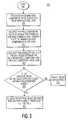
- FIG. 3an alternative contouring detection process 300 of the present invention is shown.
- display processor 70identifies a predetermined span of pixel component values (e.g., an 8 pixel span). Afterwards, at step 310 , processor 70 calculates a running pixel component value sum over the predetermined pixel span. Next, at step 315 , processor 70 multiplies the pixel component value at or near the center (e.g., the 4 th pixel component value) of the predetermined pixel span (e.g., 8 pixels) by the total number of pixel component values (e.g., 8) in the pixel span.
- the centere.g., the 4 th pixel component value
- processor 70multiplies the pixel component value at or near the center (e.g., the 4 th pixel component value) of the predetermined pixel span (e.g., 8 pixels) by the total number of pixel component values (e.g., 8) in the pixel span.
- Processor 70calculates the absolute value of the difference between the multiplied pixel component value and the pixel component value sum.
- processor 70determines if the absolute value of the calculated difference is within a predetermined range. One exemplary range is if the absolute value of the calculated difference is greater than 3 and less than 9. If not, processor 70 , at step 330 , does not alter the center pixel value. If so, processor 70 , at step 335 , replaces the center (or near center) pixel value in accordance with the contouring reduction process of FIG. 4, FIG. 5 or FIG. 6, as discussed in further detail below.
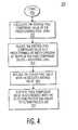
- processor 70After it has been determined that the magnitude difference test of FIG. 2 or the averaging test of FIG. 3 has been passed, processor 70 , at step 405 , initiates the execution of the contouring reduction process 400 . Initially, at step 410 , processor 70 calculates the average pixel component value of the predetermined pixel span. Next, at step 415 , processor 70 reduces (e.g., rounds or truncates) the average pixel component value to a predetermined bit width (i.e., the original bit width of the pixel component values plus an additional number of least significant bits (LSBs)).
- LSBsleast significant bits
- processor 70replaces the center or near-center pixel component value (e.g., the 4 th pixel value of an 8 pixel span) with the reduced average value.
- Processor 70tests the next pixel component value in accordance with contouring detection process 200 (shown in FIG. 2) and/or contouring detection process 300 (shown in FIG. 3 ).
- contouring detection process 200shown in FIG. 2
- contouring detection process 300shown in FIG. 3
- FIG. 9A graphical comparison of an exemplary sequence of input pixel component values (shown in FIG. 7) and a sequence of output pixel component values generated by contouring reduction process 400 is shown in FIG. 9 wherein a single LSB has been added.
- processor 70After it has been determined that the magnitude difference test of FIG. 2 or the averaging test of FIG. 3 has been passed, processor 70 , at step 505 , initiates the execution of the contouring reduction process 500 . Initially, at step 510 , processor 70 calculates the average pixel component value of the predetermined pixel span. Afterwards, at step 515 , processor 70 reduces (e.g., rounds or truncates) the average value to the nearest integer to generate a new pixel component value.
- processor 70replaces the center or near-center pixel component value (e.g., the 4 th pixel value of an 8 pixel span) with the reduced average pixel component value.
- Processor 70tests the next pixel component value in accordance with contouring detection process 200 (shown in FIG. 2) and/or contouring detection process 300 (shown in FIG. 3 ).
- contouring detection process 200shown in FIG. 2
- contouring detection process 300shown in FIG. 3
- FIG. 8A graphical comparison of an exemplary sequence of input pixel component values (shown in FIG. 7) and of a sequence of output pixel component values generated by contouring reduction process 500 is shown in FIG. 8 .
- processor 70After it has been determined that the magnitude difference test of FIG. 2 or the averaging test of FIG. 3 has been passed, processor 70 , at step 605 , initiates the execution of the contouring reduction process 600 .
- processor 70calculates the average pixel component value of the predetermined pixel span. For example, if the bit width of each pixel component value in an 8-pixel span is 8 bits, the bit width of the average pixel component value will be 11 bits.
- processor 70adds a dither signal to the average to generate a new pixel component value.
- the dither signalmay be an alternating signal such as, but not limited to, a string of alternating ones and zeroes (e.g., 1, 0, 1, 0, 1, 0 . . . ) or the dithering signal could be implemented with a recursive rounding circuit, as known by those skilled in the art.
- a two state dither signal of alternating ones and zeroescan be added to the 11-bit average using a 9-bit adder. To do so the 11-bit average is truncated to a 9-bit average by discarding the two LSBs of the 11-bit average and then adding the two state dither signal (via the 9 bit adder) to the least significant bit of the 9-bit average.
- the two state dither signalcan be added to the 11-bit average using an 11-bit adder. To do so the two state dither signal is added (via the 11-bit adder) to the 3 rd LSB of the 11-bit average.
- processor 70truncates the dithered pixel component value to the desired bit width (e.g., the original bit width of the pixel component values). For example, the 9 bit dithered average is truncated to an 8 bit dithered average by removing the LSB or the 11 bit dithered signal is truncated to an 8 bit dithered average by removing the three LSBs.
- processor 70replaces the center or near-center pixel component value (e.g., the 4 th pixel value of the 8 pixel span) with the truncated pixel component value.
- Processor 70tests the next pixel component value in accordance with contouring detection process 200 (shown in FIG. 2) and/or contouring detection process 300 (shown in FIG. 3 ).
- contouring detection process 200shown in FIG. 2
- contouring detection process 300shown in FIG. 3
- FIG. 11A graphical comparison of an exemplary sequence of input pixel component values (shown in FIG. 10) and of a sequence of output pixel component values generated by contouring reduction process 600 is shown in FIG. 11 .
Landscapes
- Engineering & Computer Science (AREA)
- Physics & Mathematics (AREA)
- General Physics & Mathematics (AREA)
- Theoretical Computer Science (AREA)
- Multimedia (AREA)
- Image Processing (AREA)
- Controls And Circuits For Display Device (AREA)
- Facsimile Image Signal Circuits (AREA)
- Control Of Indicators Other Than Cathode Ray Tubes (AREA)
- Liquid Crystal Display Device Control (AREA)
- Picture Signal Circuits (AREA)
- Image Analysis (AREA)
Abstract
Description
Claims (28)
Priority Applications (11)
| Application Number | Priority Date | Filing Date | Title |
|---|---|---|---|
| US10/056,595US6647152B2 (en) | 2002-01-25 | 2002-01-25 | Method and system for contouring reduction |
| KR1020107016890AKR20100089906A (en) | 2002-01-25 | 2003-01-17 | Method and system for contouring reduction |
| EP03703878.3AEP1468397A4 (en) | 2002-01-25 | 2003-01-17 | Method and system for contouring reduction |
| KR1020047011454AKR101000718B1 (en) | 2002-01-25 | 2003-01-17 | Method and system for contour reduction |
| CNB038026538ACN1307592C (en) | 2002-01-25 | 2003-01-17 | Method and system for profile reduction |
| PCT/US2003/001525WO2003065293A1 (en) | 2002-01-25 | 2003-01-17 | Method and system for contouring reduction |
| BR0307078-6ABR0307078A (en) | 2002-01-25 | 2003-01-17 | Process and system for contour reduction |
| MXPA04007139AMXPA04007139A (en) | 2002-01-25 | 2003-01-17 | Method and system for contouring reduction. |
| JP2003564810AJP4740539B2 (en) | 2002-01-25 | 2003-01-17 | Method and system for removing contouring artifacts |
| TW092101006ATW591936B (en) | 2002-01-25 | 2003-01-17 | Method and system for contouring reduction |
| MYPI20030243AMY134337A (en) | 2002-01-25 | 2003-01-24 | Method and system for contouring reduction |
Applications Claiming Priority (1)
| Application Number | Priority Date | Filing Date | Title |
|---|---|---|---|
| US10/056,595US6647152B2 (en) | 2002-01-25 | 2002-01-25 | Method and system for contouring reduction |
Publications (2)
| Publication Number | Publication Date |
|---|---|
| US20030142878A1 US20030142878A1 (en) | 2003-07-31 |
| US6647152B2true US6647152B2 (en) | 2003-11-11 |
Family
ID=27609300
Family Applications (1)
| Application Number | Title | Priority Date | Filing Date |
|---|---|---|---|
| US10/056,595Expired - LifetimeUS6647152B2 (en) | 2002-01-25 | 2002-01-25 | Method and system for contouring reduction |
Country Status (10)
| Country | Link |
|---|---|
| US (1) | US6647152B2 (en) |
| EP (1) | EP1468397A4 (en) |
| JP (1) | JP4740539B2 (en) |
| KR (2) | KR20100089906A (en) |
| CN (1) | CN1307592C (en) |
| BR (1) | BR0307078A (en) |
| MX (1) | MXPA04007139A (en) |
| MY (1) | MY134337A (en) |
| TW (1) | TW591936B (en) |
| WO (1) | WO2003065293A1 (en) |
Cited By (28)
| Publication number | Priority date | Publication date | Assignee | Title |
|---|---|---|---|---|
| US20040051717A1 (en)* | 2002-08-22 | 2004-03-18 | Rohm Co., Ltd | Display unit |
| US20040160455A1 (en)* | 2002-07-30 | 2004-08-19 | Sebastien Weitbruch | Method and device for processing video data for display on a display device |
| US20040239587A1 (en)* | 2003-03-28 | 2004-12-02 | Haruhiko Murata | Display processor |
| US20070229426A1 (en)* | 2006-04-03 | 2007-10-04 | L.G. Philips Lcd Co., Ltd | Apparatus and method of converting data, apparatus and method of driving image display device using the same |
| US20070248164A1 (en)* | 2006-04-07 | 2007-10-25 | Microsoft Corporation | Quantization adjustment based on texture level |
| US20080252655A1 (en)* | 2007-04-16 | 2008-10-16 | Texas Instruments Incorporated | Techniques for efficient dithering |
| US7580584B2 (en) | 2003-07-18 | 2009-08-25 | Microsoft Corporation | Adaptive multiple quantization |
| US7602851B2 (en) | 2003-07-18 | 2009-10-13 | Microsoft Corporation | Intelligent differential quantization of video coding |
| US20100118980A1 (en)* | 2004-11-30 | 2010-05-13 | Qin-Fan Zhu | System, method, and apparatus for displaying pictures |
| US20100142808A1 (en)* | 2007-01-19 | 2010-06-10 | Sitaram Bhagavat | Identifying banding in digital images |
| US7738554B2 (en) | 2003-07-18 | 2010-06-15 | Microsoft Corporation | DC coefficient signaling at small quantization step sizes |
| US7801383B2 (en) | 2004-05-15 | 2010-09-21 | Microsoft Corporation | Embedded scalar quantizers with arbitrary dead-zone ratios |
| US7974340B2 (en) | 2006-04-07 | 2011-07-05 | Microsoft Corporation | Adaptive B-picture quantization control |
| US8059721B2 (en) | 2006-04-07 | 2011-11-15 | Microsoft Corporation | Estimating sample-domain distortion in the transform domain with rounding compensation |
| US8130828B2 (en) | 2006-04-07 | 2012-03-06 | Microsoft Corporation | Adjusting quantization to preserve non-zero AC coefficients |
| US8184694B2 (en) | 2006-05-05 | 2012-05-22 | Microsoft Corporation | Harmonic quantizer scale |
| US8189933B2 (en) | 2008-03-31 | 2012-05-29 | Microsoft Corporation | Classifying and controlling encoding quality for textured, dark smooth and smooth video content |
| US8218624B2 (en) | 2003-07-18 | 2012-07-10 | Microsoft Corporation | Fractional quantization step sizes for high bit rates |
| US8238424B2 (en) | 2007-02-09 | 2012-08-07 | Microsoft Corporation | Complexity-based adaptive preprocessing for multiple-pass video compression |
| US8243797B2 (en) | 2007-03-30 | 2012-08-14 | Microsoft Corporation | Regions of interest for quality adjustments |
| US8331438B2 (en) | 2007-06-05 | 2012-12-11 | Microsoft Corporation | Adaptive selection of picture-level quantization parameters for predicted video pictures |
| US8422546B2 (en) | 2005-05-25 | 2013-04-16 | Microsoft Corporation | Adaptive video encoding using a perceptual model |
| US8442337B2 (en) | 2007-04-18 | 2013-05-14 | Microsoft Corporation | Encoding adjustments for animation content |
| US8498335B2 (en) | 2007-03-26 | 2013-07-30 | Microsoft Corporation | Adaptive deadzone size adjustment in quantization |
| US8503536B2 (en) | 2006-04-07 | 2013-08-06 | Microsoft Corporation | Quantization adjustments for DC shift artifacts |
| US8819760B2 (en) | 2007-01-05 | 2014-08-26 | Marvell World Trade Ltd. | Methods and systems for improving low-resolution video |
| US8897359B2 (en) | 2008-06-03 | 2014-11-25 | Microsoft Corporation | Adaptive quantization for enhancement layer video coding |
| US10554985B2 (en) | 2003-07-18 | 2020-02-04 | Microsoft Technology Licensing, Llc | DC coefficient signaling at small quantization step sizes |
Families Citing this family (11)
| Publication number | Priority date | Publication date | Assignee | Title |
|---|---|---|---|---|
| US6885383B2 (en)* | 2002-03-08 | 2005-04-26 | David Muresan | Moving-pixels procedure for digital picture edge-smoothing |
| US7542620B1 (en)* | 2004-08-16 | 2009-06-02 | Apple Inc. | Robust temporal dithering and filtering |
| KR100594738B1 (en)* | 2004-12-28 | 2006-06-30 | 삼성전자주식회사 | Device for eliminating contours caused by bit depth reduction |
| JP4463705B2 (en) | 2005-03-01 | 2010-05-19 | 三菱電機株式会社 | Image display device and image display method |
| KR100627615B1 (en)* | 2005-12-29 | 2006-09-25 | 엠텍비젼 주식회사 | Noise Canceller with Adjustable Threshold |
| JP4455513B2 (en)* | 2006-02-13 | 2010-04-21 | 三菱電機株式会社 | Image processing method, image processing apparatus, and image display apparatus |
| US8270498B2 (en)* | 2009-03-26 | 2012-09-18 | Apple Inc. | Dynamic dithering for video compression |
| US8860750B2 (en)* | 2011-03-08 | 2014-10-14 | Apple Inc. | Devices and methods for dynamic dithering |
| KR102007815B1 (en)* | 2012-12-12 | 2019-08-07 | 엘지디스플레이 주식회사 | Display device and image data processing method thereof |
| US9092856B2 (en)* | 2013-10-31 | 2015-07-28 | Stmicroelectronics Asia Pacific Pte. Ltd. | Recursive de-banding filter for digital images |
| CN108322723B (en)* | 2018-02-06 | 2020-01-24 | 深圳创维-Rgb电子有限公司 | A color distortion compensation method, device and TV |
Citations (13)
| Publication number | Priority date | Publication date | Assignee | Title |
|---|---|---|---|---|
| US4630104A (en) | 1983-06-24 | 1986-12-16 | Victor Company Of Japan, Ltd. | Circuit arrangement for removing noise of a color video signal |
| US5101452A (en) | 1990-12-17 | 1992-03-31 | Eastman Kodak Company | Apparatus and method for dynamic step quantization |
| US5138303A (en) | 1989-10-31 | 1992-08-11 | Microsoft Corporation | Method and apparatus for displaying color on a computer output device using dithering techniques |
| US5374963A (en) | 1990-06-01 | 1994-12-20 | Thomson Consumer Electronics, Inc. | Picture resolution enhancement with dithering and dedithering |
| US5408338A (en)* | 1992-02-19 | 1995-04-18 | Ricoh Company, Ltd. | Image processing unit processing pixel data according to scan line density |
| US5579054A (en)* | 1995-04-21 | 1996-11-26 | Eastman Kodak Company | System and method for creating high-quality stills from interlaced video |
| US5598482A (en) | 1992-02-11 | 1997-01-28 | Eastman Kodak Company | Image rendering system and associated method for minimizing contours in a quantized digital color image |
| US5777624A (en) | 1996-01-02 | 1998-07-07 | Intel Corporation | Method and apparatus for eliminating visual artifacts caused by diffusing errors in a decimated video signal |
| US5835117A (en)* | 1996-05-31 | 1998-11-10 | Eastman Kodak Company | Nonlinear dithering to reduce neutral toe color shifts |
| US5838298A (en) | 1987-02-13 | 1998-11-17 | Canon Kabushiki Kaisha | Image processing apparatus and method for smoothing stairway-like portions of a contour line of an image |
| US6040876A (en) | 1995-10-13 | 2000-03-21 | Texas Instruments Incorporated | Low intensity contouring and color shift reduction using dither |
| US6052491A (en) | 1996-01-26 | 2000-04-18 | Texas Instruments Incorporated | Non-monotonic contour diffusion and algorithm |
| US6147671A (en) | 1994-09-13 | 2000-11-14 | Intel Corporation | Temporally dissolved dithering |
Family Cites Families (20)
| Publication number | Priority date | Publication date | Assignee | Title |
|---|---|---|---|---|
| JPS6319982A (en)* | 1986-07-12 | 1988-01-27 | Fujitsu Ltd | Video printer gradation control method |
| JP2644491B2 (en)* | 1987-05-18 | 1997-08-25 | キヤノン株式会社 | Image processing device |
| JPH03226177A (en)* | 1990-01-31 | 1991-10-07 | Fuji Xerox Co Ltd | Gradation conversion processing unit |
| US5218649A (en) | 1990-05-04 | 1993-06-08 | U S West Advanced Technologies, Inc. | Image enhancement system |
| JPH0490680A (en)* | 1990-08-06 | 1992-03-24 | Oki Electric Ind Co Ltd | Picture binarizing method |
| JPH04165874A (en)* | 1990-10-30 | 1992-06-11 | Canon Inc | Digital signal processor |
| JPH06152992A (en)* | 1992-10-29 | 1994-05-31 | Canon Inc | Image processing method and apparatus |
| JPH06225179A (en)* | 1993-01-21 | 1994-08-12 | Sony Corp | Quantizer for picture signal |
| JP3361355B2 (en)* | 1993-05-14 | 2003-01-07 | 株式会社リコー | Image processing device |
| US5651078A (en)* | 1994-07-18 | 1997-07-22 | Thomson Consumer Electronics, Inc. | Method and apparatus for reducing contouring in video compression |
| KR100414432B1 (en)* | 1995-03-24 | 2004-03-18 | 마츠시타 덴끼 산교 가부시키가이샤 | Contour extraction device |
| JPH0944648A (en)* | 1995-08-01 | 1997-02-14 | Sony Corp | Image processing device and method therefor |
| FR2769453B1 (en)* | 1997-10-06 | 2000-01-07 | Telediffusion Fse | METHOD FOR EVALUATING THE DEGRADATION OF A VIDEO IMAGE INTRODUCED BY A CODING AND / OR STORAGE AND / OR DIGITAL TRANSMISSION SYSTEM |
| JPH11272228A (en)* | 1998-03-19 | 1999-10-08 | Mitsubishi Electric Corp | Display driving apparatus and method |
| ATE306545T1 (en)* | 1998-03-31 | 2005-10-15 | Bioreal Inc | CULTURE DEVICE FOR FINE ALGAE |
| US6324310B1 (en)* | 1998-06-02 | 2001-11-27 | Digital Persona, Inc. | Method and apparatus for scanning a fingerprint using a linear sensor |
| JP3738574B2 (en)* | 1998-09-18 | 2006-01-25 | 富士ゼロックス株式会社 | Image information encoding device |
| JP2001036756A (en)* | 1999-07-15 | 2001-02-09 | Canon Inc | Image processing method and apparatus |
| JP2001136535A (en)* | 1999-08-25 | 2001-05-18 | Fuji Xerox Co Ltd | Image-encoding device and quantization characteristic determining device |
| JP2001092954A (en)* | 1999-09-20 | 2001-04-06 | Matsushita Electric Ind Co Ltd | Rounding device |
- 2002
- 2002-01-25USUS10/056,595patent/US6647152B2/ennot_activeExpired - Lifetime
- 2003
- 2003-01-17WOPCT/US2003/001525patent/WO2003065293A1/enactiveApplication Filing
- 2003-01-17JPJP2003564810Apatent/JP4740539B2/ennot_activeExpired - Fee Related
- 2003-01-17CNCNB038026538Apatent/CN1307592C/ennot_activeExpired - Fee Related
- 2003-01-17KRKR1020107016890Apatent/KR20100089906A/ennot_activeCeased
- 2003-01-17KRKR1020047011454Apatent/KR101000718B1/ennot_activeExpired - Fee Related
- 2003-01-17TWTW092101006Apatent/TW591936B/ennot_activeIP Right Cessation
- 2003-01-17EPEP03703878.3Apatent/EP1468397A4/ennot_activeWithdrawn
- 2003-01-17MXMXPA04007139Apatent/MXPA04007139A/enactiveIP Right Grant
- 2003-01-17BRBR0307078-6Apatent/BR0307078A/ennot_activeApplication Discontinuation
- 2003-01-24MYMYPI20030243Apatent/MY134337A/enunknown
Patent Citations (13)
| Publication number | Priority date | Publication date | Assignee | Title |
|---|---|---|---|---|
| US4630104A (en) | 1983-06-24 | 1986-12-16 | Victor Company Of Japan, Ltd. | Circuit arrangement for removing noise of a color video signal |
| US5838298A (en) | 1987-02-13 | 1998-11-17 | Canon Kabushiki Kaisha | Image processing apparatus and method for smoothing stairway-like portions of a contour line of an image |
| US5138303A (en) | 1989-10-31 | 1992-08-11 | Microsoft Corporation | Method and apparatus for displaying color on a computer output device using dithering techniques |
| US5374963A (en) | 1990-06-01 | 1994-12-20 | Thomson Consumer Electronics, Inc. | Picture resolution enhancement with dithering and dedithering |
| US5101452A (en) | 1990-12-17 | 1992-03-31 | Eastman Kodak Company | Apparatus and method for dynamic step quantization |
| US5598482A (en) | 1992-02-11 | 1997-01-28 | Eastman Kodak Company | Image rendering system and associated method for minimizing contours in a quantized digital color image |
| US5408338A (en)* | 1992-02-19 | 1995-04-18 | Ricoh Company, Ltd. | Image processing unit processing pixel data according to scan line density |
| US6147671A (en) | 1994-09-13 | 2000-11-14 | Intel Corporation | Temporally dissolved dithering |
| US5579054A (en)* | 1995-04-21 | 1996-11-26 | Eastman Kodak Company | System and method for creating high-quality stills from interlaced video |
| US6040876A (en) | 1995-10-13 | 2000-03-21 | Texas Instruments Incorporated | Low intensity contouring and color shift reduction using dither |
| US5777624A (en) | 1996-01-02 | 1998-07-07 | Intel Corporation | Method and apparatus for eliminating visual artifacts caused by diffusing errors in a decimated video signal |
| US6052491A (en) | 1996-01-26 | 2000-04-18 | Texas Instruments Incorporated | Non-monotonic contour diffusion and algorithm |
| US5835117A (en)* | 1996-05-31 | 1998-11-10 | Eastman Kodak Company | Nonlinear dithering to reduce neutral toe color shifts |
Cited By (48)
| Publication number | Priority date | Publication date | Assignee | Title |
|---|---|---|---|---|
| US20040160455A1 (en)* | 2002-07-30 | 2004-08-19 | Sebastien Weitbruch | Method and device for processing video data for display on a display device |
| US7973801B2 (en) | 2002-07-30 | 2011-07-05 | Thomson Licensing | Method and device for processing video data for display on a display device |
| US20040051717A1 (en)* | 2002-08-22 | 2004-03-18 | Rohm Co., Ltd | Display unit |
| US20040239587A1 (en)* | 2003-03-28 | 2004-12-02 | Haruhiko Murata | Display processor |
| US7580584B2 (en) | 2003-07-18 | 2009-08-25 | Microsoft Corporation | Adaptive multiple quantization |
| US8218624B2 (en) | 2003-07-18 | 2012-07-10 | Microsoft Corporation | Fractional quantization step sizes for high bit rates |
| US10063863B2 (en) | 2003-07-18 | 2018-08-28 | Microsoft Technology Licensing, Llc | DC coefficient signaling at small quantization step sizes |
| US7602851B2 (en) | 2003-07-18 | 2009-10-13 | Microsoft Corporation | Intelligent differential quantization of video coding |
| US10659793B2 (en) | 2003-07-18 | 2020-05-19 | Microsoft Technology Licensing, Llc | DC coefficient signaling at small quantization step sizes |
| US9313509B2 (en) | 2003-07-18 | 2016-04-12 | Microsoft Technology Licensing, Llc | DC coefficient signaling at small quantization step sizes |
| US7738554B2 (en) | 2003-07-18 | 2010-06-15 | Microsoft Corporation | DC coefficient signaling at small quantization step sizes |
| US10554985B2 (en) | 2003-07-18 | 2020-02-04 | Microsoft Technology Licensing, Llc | DC coefficient signaling at small quantization step sizes |
| US7801383B2 (en) | 2004-05-15 | 2010-09-21 | Microsoft Corporation | Embedded scalar quantizers with arbitrary dead-zone ratios |
| US8411760B2 (en)* | 2004-11-30 | 2013-04-02 | Broadcom Corporation | System, method, and apparatus for displaying pictures |
| US9055297B2 (en) | 2004-11-30 | 2015-06-09 | Broadcom Corporation | System, method, and apparatus for displaying pictures |
| US20100118980A1 (en)* | 2004-11-30 | 2010-05-13 | Qin-Fan Zhu | System, method, and apparatus for displaying pictures |
| US8422546B2 (en) | 2005-05-25 | 2013-04-16 | Microsoft Corporation | Adaptive video encoding using a perceptual model |
| US20070229426A1 (en)* | 2006-04-03 | 2007-10-04 | L.G. Philips Lcd Co., Ltd | Apparatus and method of converting data, apparatus and method of driving image display device using the same |
| US8446352B2 (en)* | 2006-04-03 | 2013-05-21 | Lg Display Co., Ltd. | Apparatus and method of converting data, apparatus and method of driving image display device using the same |
| US8767822B2 (en) | 2006-04-07 | 2014-07-01 | Microsoft Corporation | Quantization adjustment based on texture level |
| US20070248164A1 (en)* | 2006-04-07 | 2007-10-25 | Microsoft Corporation | Quantization adjustment based on texture level |
| US8503536B2 (en) | 2006-04-07 | 2013-08-06 | Microsoft Corporation | Quantization adjustments for DC shift artifacts |
| US8130828B2 (en) | 2006-04-07 | 2012-03-06 | Microsoft Corporation | Adjusting quantization to preserve non-zero AC coefficients |
| US8249145B2 (en) | 2006-04-07 | 2012-08-21 | Microsoft Corporation | Estimating sample-domain distortion in the transform domain with rounding compensation |
| US8059721B2 (en) | 2006-04-07 | 2011-11-15 | Microsoft Corporation | Estimating sample-domain distortion in the transform domain with rounding compensation |
| US7995649B2 (en) | 2006-04-07 | 2011-08-09 | Microsoft Corporation | Quantization adjustment based on texture level |
| US7974340B2 (en) | 2006-04-07 | 2011-07-05 | Microsoft Corporation | Adaptive B-picture quantization control |
| US9967561B2 (en) | 2006-05-05 | 2018-05-08 | Microsoft Technology Licensing, Llc | Flexible quantization |
| US8588298B2 (en) | 2006-05-05 | 2013-11-19 | Microsoft Corporation | Harmonic quantizer scale |
| US8711925B2 (en) | 2006-05-05 | 2014-04-29 | Microsoft Corporation | Flexible quantization |
| US8184694B2 (en) | 2006-05-05 | 2012-05-22 | Microsoft Corporation | Harmonic quantizer scale |
| US8819760B2 (en) | 2007-01-05 | 2014-08-26 | Marvell World Trade Ltd. | Methods and systems for improving low-resolution video |
| US8532375B2 (en) | 2007-01-19 | 2013-09-10 | Thomson Licensing | Identifying banding in digital images |
| US8644601B2 (en) | 2007-01-19 | 2014-02-04 | Thomson Licensing | Reducing contours in digital images |
| US20100142808A1 (en)* | 2007-01-19 | 2010-06-10 | Sitaram Bhagavat | Identifying banding in digital images |
| US8238424B2 (en) | 2007-02-09 | 2012-08-07 | Microsoft Corporation | Complexity-based adaptive preprocessing for multiple-pass video compression |
| US8498335B2 (en) | 2007-03-26 | 2013-07-30 | Microsoft Corporation | Adaptive deadzone size adjustment in quantization |
| US8243797B2 (en) | 2007-03-30 | 2012-08-14 | Microsoft Corporation | Regions of interest for quality adjustments |
| US8576908B2 (en) | 2007-03-30 | 2013-11-05 | Microsoft Corporation | Regions of interest for quality adjustments |
| US7864191B2 (en)* | 2007-04-16 | 2011-01-04 | Texas Instruments Incorporated | Techniques for efficient dithering |
| US20080252655A1 (en)* | 2007-04-16 | 2008-10-16 | Texas Instruments Incorporated | Techniques for efficient dithering |
| US8442337B2 (en) | 2007-04-18 | 2013-05-14 | Microsoft Corporation | Encoding adjustments for animation content |
| US8331438B2 (en) | 2007-06-05 | 2012-12-11 | Microsoft Corporation | Adaptive selection of picture-level quantization parameters for predicted video pictures |
| US8189933B2 (en) | 2008-03-31 | 2012-05-29 | Microsoft Corporation | Classifying and controlling encoding quality for textured, dark smooth and smooth video content |
| US9185418B2 (en) | 2008-06-03 | 2015-11-10 | Microsoft Technology Licensing, Llc | Adaptive quantization for enhancement layer video coding |
| US8897359B2 (en) | 2008-06-03 | 2014-11-25 | Microsoft Corporation | Adaptive quantization for enhancement layer video coding |
| US9571840B2 (en) | 2008-06-03 | 2017-02-14 | Microsoft Technology Licensing, Llc | Adaptive quantization for enhancement layer video coding |
| US10306227B2 (en) | 2008-06-03 | 2019-05-28 | Microsoft Technology Licensing, Llc | Adaptive quantization for enhancement layer video coding |
Also Published As
| Publication number | Publication date |
|---|---|
| US20030142878A1 (en) | 2003-07-31 |
| KR20100089906A (en) | 2010-08-12 |
| CN1623165A (en) | 2005-06-01 |
| BR0307078A (en) | 2004-12-28 |
| JP4740539B2 (en) | 2011-08-03 |
| WO2003065293A1 (en) | 2003-08-07 |
| TW591936B (en) | 2004-06-11 |
| TW200302662A (en) | 2003-08-01 |
| KR20040075108A (en) | 2004-08-26 |
| EP1468397A1 (en) | 2004-10-20 |
| MXPA04007139A (en) | 2004-10-29 |
| CN1307592C (en) | 2007-03-28 |
| MY134337A (en) | 2007-12-31 |
| JP2005516260A (en) | 2005-06-02 |
| KR101000718B1 (en) | 2010-12-10 |
| EP1468397A4 (en) | 2017-05-10 |
Similar Documents
| Publication | Publication Date | Title |
|---|---|---|
| US6647152B2 (en) | Method and system for contouring reduction | |
| US4903125A (en) | Method and apparatus for conveying information signals | |
| US9532101B2 (en) | Digital broadcast receiver unit | |
| AU698954B2 (en) | On screen display arrangement for a digital video signal processing system | |
| US7750938B2 (en) | Method and system for maintaining even tube burn-in | |
| EP1158810B1 (en) | Recording medium | |
| CN1191655A (en) | Animated "on-screen" display device for MPEG video signal processing systems | |
| US7830968B1 (en) | Apparatus for providing a video lip sync delay and method therefore | |
| KR101075969B1 (en) | Method and apparatus for preventing error propagation in a video sequence | |
| KR100768682B1 (en) | Method and system for pixel data buffering | |
| JP2002135786A (en) | Receiver and digital data decoding method | |
| US20060093037A1 (en) | Device and method for decoding and digital broadcast receiving apparatus | |
| US7554612B2 (en) | Method and system for buffering pixel data | |
| KR19990049348A (en) | FRAME RATE CONVERTER AND METHOD USING MOTION VECTOR. | |
| US7053960B2 (en) | Systems and methods for adjusting image contrast | |
| KR100190612B1 (en) | Digital satellite video receiving system with a picture pausing function | |
| JPH10271363A (en) | Video signal processor, encoded video signal decoder using the same and digital broadcasting receiver/decoder |
Legal Events
| Date | Code | Title | Description |
|---|---|---|---|
| AS | Assignment | Owner name:THOMSON LICENSING S.A., FRANCE Free format text:ASSIGNMENT OF ASSIGNORS INTEREST;ASSIGNORS:WILLIS, DONALD HENRY;HAGUE, JOHN ALAN;REEL/FRAME:012574/0170 Effective date:20020125 | |
| STCF | Information on status: patent grant | Free format text:PATENTED CASE | |
| FPAY | Fee payment | Year of fee payment:4 | |
| FPAY | Fee payment | Year of fee payment:8 | |
| FPAY | Fee payment | Year of fee payment:12 | |
| AS | Assignment | Owner name:THOMSON LICENSING, FRANCE Free format text:CHANGE OF NAME;ASSIGNOR:THOMSON LICENSING S.A.;REEL/FRAME:042303/0268 Effective date:20100505 | |
| AS | Assignment | Owner name:THOMSON LICENSING DTV, FRANCE Free format text:ASSIGNMENT OF ASSIGNORS INTEREST;ASSIGNOR:THOMSON LICENSING;REEL/FRAME:043302/0965 Effective date:20160104 | |
| AS | Assignment | Owner name:INTERDIGITAL MADISON PATENT HOLDINGS, FRANCE Free format text:ASSIGNMENT OF ASSIGNORS INTEREST;ASSIGNOR:THOMSON LICENSING DTV;REEL/FRAME:046763/0001 Effective date:20180723 |