US6646799B1 - System and method for combining multiple energy bands to improve scene viewing - Google Patents
System and method for combining multiple energy bands to improve scene viewingDownload PDFInfo
- Publication number
- US6646799B1 US6646799B1US09/651,111US65111100AUS6646799B1US 6646799 B1US6646799 B1US 6646799B1US 65111100 AUS65111100 AUS 65111100AUS 6646799 B1US6646799 B1US 6646799B1
- Authority
- US
- United States
- Prior art keywords
- radiation
- band
- imaging
- onto
- sensor
- Prior art date
- Legal status (The legal status is an assumption and is not a legal conclusion. Google has not performed a legal analysis and makes no representation as to the accuracy of the status listed.)
- Expired - Lifetime, expires
Links
Images


Classifications
- G—PHYSICS
- G01—MEASURING; TESTING
- G01J—MEASUREMENT OF INTENSITY, VELOCITY, SPECTRAL CONTENT, POLARISATION, PHASE OR PULSE CHARACTERISTICS OF INFRARED, VISIBLE OR ULTRAVIOLET LIGHT; COLORIMETRY; RADIATION PYROMETRY
- G01J3/00—Spectrometry; Spectrophotometry; Monochromators; Measuring colours
- G01J3/02—Details
- G01J3/0205—Optical elements not provided otherwise, e.g. optical manifolds, diffusers, windows
- G01J3/0208—Optical elements not provided otherwise, e.g. optical manifolds, diffusers, windows using focussing or collimating elements, e.g. lenses or mirrors; performing aberration correction
- G—PHYSICS
- G01—MEASURING; TESTING
- G01J—MEASUREMENT OF INTENSITY, VELOCITY, SPECTRAL CONTENT, POLARISATION, PHASE OR PULSE CHARACTERISTICS OF INFRARED, VISIBLE OR ULTRAVIOLET LIGHT; COLORIMETRY; RADIATION PYROMETRY
- G01J3/00—Spectrometry; Spectrophotometry; Monochromators; Measuring colours
- G01J3/28—Investigating the spectrum
- G01J3/30—Measuring the intensity of spectral lines directly on the spectrum itself
- G01J3/32—Investigating bands of a spectrum in sequence by a single detector
- G—PHYSICS
- G02—OPTICS
- G02B—OPTICAL ELEMENTS, SYSTEMS OR APPARATUS
- G02B13/00—Optical objectives specially designed for the purposes specified below
- G02B13/14—Optical objectives specially designed for the purposes specified below for use with infrared or ultraviolet radiation
- G02B13/146—Optical objectives specially designed for the purposes specified below for use with infrared or ultraviolet radiation with corrections for use in multiple wavelength bands, such as infrared and visible light, e.g. FLIR systems
- G—PHYSICS
- G02—OPTICS
- G02B—OPTICAL ELEMENTS, SYSTEMS OR APPARATUS
- G02B13/00—Optical objectives specially designed for the purposes specified below
- G02B13/16—Optical objectives specially designed for the purposes specified below for use in conjunction with image converters or intensifiers, or for use with projectors, e.g. objectives for projection TV
- G—PHYSICS
- G02—OPTICS
- G02B—OPTICAL ELEMENTS, SYSTEMS OR APPARATUS
- G02B17/00—Systems with reflecting surfaces, with or without refracting elements
- G02B17/08—Catadioptric systems
- G—PHYSICS
- G02—OPTICS
- G02B—OPTICAL ELEMENTS, SYSTEMS OR APPARATUS
- G02B17/00—Systems with reflecting surfaces, with or without refracting elements
- G02B17/08—Catadioptric systems
- G02B17/0804—Catadioptric systems using two curved mirrors
- G—PHYSICS
- G02—OPTICS
- G02B—OPTICAL ELEMENTS, SYSTEMS OR APPARATUS
- G02B17/00—Systems with reflecting surfaces, with or without refracting elements
- G02B17/08—Catadioptric systems
- G02B17/0804—Catadioptric systems using two curved mirrors
- G02B17/0808—Catadioptric systems using two curved mirrors on-axis systems with at least one of the mirrors having a central aperture
- G—PHYSICS
- G02—OPTICS
- G02B—OPTICAL ELEMENTS, SYSTEMS OR APPARATUS
- G02B17/00—Systems with reflecting surfaces, with or without refracting elements
- G02B17/08—Catadioptric systems
- G02B17/0852—Catadioptric systems having a field corrector only
- G—PHYSICS
- G02—OPTICS
- G02B—OPTICAL ELEMENTS, SYSTEMS OR APPARATUS
- G02B17/00—Systems with reflecting surfaces, with or without refracting elements
- G02B17/08—Catadioptric systems
- G02B17/0884—Catadioptric systems having a pupil corrector
- G—PHYSICS
- G02—OPTICS
- G02B—OPTICAL ELEMENTS, SYSTEMS OR APPARATUS
- G02B17/00—Systems with reflecting surfaces, with or without refracting elements
- G02B17/08—Catadioptric systems
- G02B17/0884—Catadioptric systems having a pupil corrector
- G02B17/0888—Catadioptric systems having a pupil corrector the corrector having at least one aspheric surface, e.g. Schmidt plates
- G—PHYSICS
- G02—OPTICS
- G02B—OPTICAL ELEMENTS, SYSTEMS OR APPARATUS
- G02B17/00—Systems with reflecting surfaces, with or without refracting elements
- G02B17/08—Catadioptric systems
- G02B17/0896—Catadioptric systems with variable magnification or multiple imaging planes, including multispectral systems
- G—PHYSICS
- G02—OPTICS
- G02B—OPTICAL ELEMENTS, SYSTEMS OR APPARATUS
- G02B23/00—Telescopes, e.g. binoculars; Periscopes; Instruments for viewing the inside of hollow bodies; Viewfinders; Optical aiming or sighting devices
- G02B23/12—Telescopes, e.g. binoculars; Periscopes; Instruments for viewing the inside of hollow bodies; Viewfinders; Optical aiming or sighting devices with means for image conversion or intensification
Definitions
- the inventionpertains generally to imaging using multiple bands of radiation and particularly to the simultaneous imaging of multiple bands of radiation to form a scene for viewing by a user.
- VIS/NIRvisible/near-wavelength infrared
- IRthermal infrared
- MWIRmid-wavelength IR
- LWIRlong-wavelength IR
- Camouflage and obscurantsare much less effective in the thermal band than in the VIS/NIR.
- thermal imagersdo not detect lasers operating at 1.06 microns. This is significant because such lasers are used for target ranging and designation. Knowledge of such illumination by friendly or enemy forces can be vital.
- image intensification sensors operating in the VIS/NIRi.e., 0.6 to 1.1 micron range
- Uncooled IR sensorsoffer a low cost, low power approach to thermal imaging.
- LWIRlong wave infrared
- uncooled thermal imagingis excellent for many military applications because items of interest (e.g., enemy soldiers, vehicles, disrupted earth) almost always emit more in-band (in this case IR) energy than the background.
- Other applications for uncooled thermal imaginginclude security, hunting, monitoring and surveillance, firefighting, search and rescue, drug enforcement, border patrol and ship navigation.
- the current uncooled devices and even those in developmente.g., 640 ⁇ 480 with 25 micron pixels
- Image intensifierstake whatever amount of light is available (e.g., moonlight, starlight, artificial lights such as street lights) and electronically intensify the light and then display the image either directly or through the use of an electronic imaging screen via a magnifier or television-type monitor. Improvements in II technology have resulted in the GEN III OMNI IV 18-mm tube offering the equivalent of more than 2300 ⁇ 2300 pixels. II covers the visible and near infrared (VIS/NIR: 0.6 to 1.1 microns) and overcomes the LWIR limitations listed above. However, II is limited by the ambient light available, targets are harder to find, and camouflage/obscurants (e.g., smoke, dust, fog) are much more effective.
- VIS/NIRvisible and near infrared
- IR imaging devicestypically provide monochrome imaging capabilities. In most situations, the ideal viewing scenario would be full color. This is of course achieved in the visible band. There are numerous situations where a user alternates between visible band viewing scenarios and IR band viewing scenarios within the span of seconds. Current imaging devices do not allow a user to either: (a) simultaneously view both the monochrome IR image and the full color visible image, or (b) change between IR monochrome imaging and full-color visible imaging without mechanically altering the imaging device or removing the device from the users field of view (e.g., as in the case of an IR helmet mounted sensor).
- the obvious synergy of multiple sensor bandsis difficult to achieve and totally impractical for handheld use via separate sensors looking alternately at the same scene.
- the solution advanced in this applicationis the development of a single sensor that can operate in multiple bands and display either one radiation band alone or multiple overlaid bands, using an appropriate color choice to distinguish the bands.
- the multiple-band sensorallows the user to look through at least one eyepiece and with the use of a switch, see scenes formed via the human eye under visible light, an II sensor, an MWIR sensor, or an LWIR sensor, either individually or superimposed.
- the deviceis equipped with multiple switching mechanisms. The first, for allowing the user to select between radiation bands and overlays, and the second, as with most thermal imaging sensors, for allowing the user to switch between “white-hot/black-hot” i.e., a polarity switch.
- a further feature of the present inventionis a multiple-band objective lens for imaging multiple bands of incoming radiation, including at least two of the visible band, the VIS/NIR band, the MWIR band or the LWIR band.
- a further feature of the present inventionis range focusing capability of the sensors which, simultaneously, is from 3 meters to infinity over a full military temperature range.
- Further features of the present inventioninclude supporting sensors and corresponding eyepiece displays as well as transmitters used to enhance the usability and efficiency of the multiple-band sensors.
- a digital compass, a laser range finder, a GPS receiver and IR video imagery componentsmay be integrated into the multiple-band sensor.
- the multiple-band sensormay also be equipped with an eyepiece for facilitating zoom magnification.
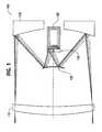
- FIG. 1is a reflective objective lens according to an embodiment of the present invention
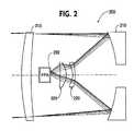
- FIG. 2is a combination reflective/refractive objective lens according to an embodiment of the present invention.
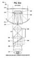
- FIGS. 3 ( a ) and 3 ( b )are compact monoculars according to embodiments of the present invention.
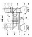
- FIGS. 4 ( a ) and 4 ( b )are compact binoculars according to embodiments of the present invention.
- FIGS. 5 ( a ) and 5 ( b )are monochromatic MTF performance graphs for NIR energy passing through a lens configuration according to an embodiment of the present invention
- FIGS. 6 ( a ) and 6 ( b )are monochromatic MTF performance graphs for LWIR energy passing through a lens configuration according to an embodiment of the present invention
- FIGS. 7 ( a )- 7 ( d )are objective lenses according to embodiments of the present invention.
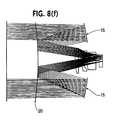
- FIGS. 8 ( a )- 8 ( f )are objective lenses according to embodiments of the present invention with FIGS. 8 ( g ) and 8 ( h ) are representative color-corrected MTF performance graphs for VIS/NIR energy passing through lens configurations 8 ( e ) and 8 ( f ), respectively;
- FIGS. 9 ( a )- 9 ( b )are objective lenses according to embodiments of the present invention.
- FIGS. 10 ( a ) and 10 ( d )are objective lenses according to embodiments of the present invention and FIGS. 10 ( b ), 10 ( c ), 10 ( e ), and 10 ( f ) are MTF performance graphs for objective lenses 10 ( a ) and 10 ( d ), respectively.
- a multiple-band sensorthere are multiple factors that must be considered in order to optimize the image quality in each band simultaneously.
- magnification trade off with the field of view that impacts the image quality and ultimately the design of the multiple-band sensorimpacts the image quality and ultimately the design of the multiple-band sensor.
- a wide field of viewis useful in wide area coverage, but limited in target identification and intelligence gathering. Too much magnification requires a heavy lens, which limits the usefulness in a handheld sensor, but is less of an issue in larger fixed (mounted) applications.
- a single objective lenssimilar to a long range camera lens and telescope, is used to image all incoming bands of energy.
- the reflective objective lensconsists of two mirrors, allowing for a longer focal length in a smaller space than a single mirror would require for the same focal length.
- This lens configuration shown in FIG. 1is known as a catadioptric configuration (imaging objectives using powered lenses and mirrors to form the image) consisting of a Cassegrain two-mirror lens with an aperture corrector and a field lens.
- the Cassegrain portion of the objective lensis a telephoto configuration, which allows it to be compact.
- Other embodimentsmay be more elaborate catadioptic set-ups to obtain the desired imaging properties of the objective lens.
- the objective lens 100 of FIG. 1comprises a combination corrector lens/aperture stop 110 , a primary component 115 , a secondary component 120 , and a field lens 125 .
- the VIS/NIR energy from the sceneimpinges upon the corrector lens/aperture stop 110 , and bounces off of the primary component 115 , which is preferably as large in diameter as the corrector lens 110 .
- the energythen reflects onto and subsequently off of a secondary component 120 that is held in front of the primary component 115 , passes through the field lens 125 and forms an image on, for example, an image intensifier (e.g., tube) 130 .
- an image intensifiere.g., tube
- primary and secondary componentsare both reflective, but this need not always be the case.
- FIG. 1illustrates the VIS/NIR imaging functionality of the multiple-band imaging system
- FIG. 2 discussed belowillustrates the MWIR and/or LWIR imaging functionality of the multiple-band imaging system.
- the objective lens 200comprises a combination corrector lens/aperture stop 210 , a primary component 215 , a secondary component 220 , and a MWIR or LWIR lens component 225 .
- Components 210 , 215 and 220are identical to 110 , 115 and 120 of FIG. 1, as these components form a single objective that is capable of imaging multiple bands of radiation, eg., VIS/NIR and MWIR and/or LWIR.
- the MWIR or LWIR energy from the sceneimpinges upon the corrector lens/aperture stop 210 , bounces off of the primary component 215 .
- the primary component 215 diameteris similar to the corrector lens aperture 210 .
- the energythen reflects onto and through a secondary component 220 that is held in front of the primary component 215 , passes through the MWIR or LWIR lens component 225 and forms an image on, for example, an IR focal plane array (IRFPA) or the like 230 .
- IRFPAIR focal plane array
- This objectiveis an example of a catadioptric system, wherein both reflective and refractive elements are used to achieve the desired focal points.
- the primary component 215is reflective and the secondary component 220 is refractive.
- FIGS. 3 ( a ) and 3 ( b )In a first preferred embodiment illustrated in FIGS. 3 ( a ) and 3 ( b ), by combining the elements of the objectives of FIG. 1 and FIG. 2, it is possible to simultaneously image the various energy bands from a scene using a single objective lens in a compact monocular 300 .
- the components utilized during the display of a night scene via a compact monocular 300include a combination corrector lens (e.g., Cleartrane®) 310 , a primary component 315 , a secondary component 320 , one or more MWIR or LWIR aberration correction lenses 325 , an IRFPA 330 , one or more field lenses 335 , an image intensifier 340 , and a combining eyepiece (e.g., ANVIS-6 NV/HUD) 345 which includes a image combiner 350 , an eyepiece 355 , and a display (e.g., active matrix electroluminescent (AMEL) display) 360 .
- thermal imager electronics and operator controlse.g., range focusing mechanism and polarity control
- Imaging and sensor electronicsare well know to those skilled in the art and will not be discussed further herein.
- all radiation 305including visible through LWIR impinges upon the combination corrector lens/aperture stop 310 .
- All radiationis reflected off of the primary component 315 and is directed towards the secondary component 320 .
- the secondary component 320is designed so as to transmit either MWIR or LWIR or both, depending on the desired application of the monocular, and to reflect VIS/NIR.
- the transmitted IRpasses through an IR component 325 for correcting aberration and impinges upon an IRFPA, where it is converted into an electronic digital image and then is displayed on, for example, a CRT, AMEL, or some other flat-panel display 360 and ultimately projected into the eye 370 of a user via an imaging system 345 .
- the VIS/NIR wavelengthsare reflected off of the secondary component 320 , pass through an aberration correction component 335 and are imaged onto an image intensifier 340 (e.g., II tube). After being intensified, the VIS/NIR scene is directly imaged onto the user's eye 370 via the imaging system 345 .
- the imaging system 345uses a beam combiner 350 and an eyepiece 355 to superimpose the images onto the user's eye 370 .
- the eyepiecemagnifies the output of the electronically intensified VIS/NIR scene and the digitized IR scene from the display onto the viewer's eye 370 .
- the output of the image intensifier 340has the characteristic yellow green color of the P 43 phosphor screen.
- the output of the IR display 360must be a different color.
- the standard ANVIS-6 NV/HUD eyepieceuses an amber display for superimposing information onto the output of the image intensifier. Thus monochrome amber is a good choice for displaying the IR image, but is merely exemplary.
- FIG. 3 ( b )the components utilized during the display of a day scene via compact monocular 300 are identical to those of FIG. 3 ( a ) with the exception of the erector lens component 342 which is used to image the visible scene in place of the image intensifier 340 from the night scene.
- the compact monocular 300allows the user to choose between multiple operation viewing modes, without the need to change objective or eyepiece lenses.
- the same scene, viewed in multiple bandse.g., VIS/NIR, MWIR, and LWIR
- the usermay view the same scene separately using at least two different imaging bands.
- a switchis provided. These modes of operation include (1) only II image of the scene, (2) only IR image of the scene, and (3) overlay of the II and IR image of the scene.
- the monocular in FIG. 3 ( b )is equipped with optics for viewing scenes during the day without the need for the image intensifier.
- the compact monocular 300 of FIG. 3is preferably sealed to avoid degradation due to exposure to the elements by the combination aberration corrector lens 310 .
- An example of a suitable sealing lensis one made of Cleartran®. While this is a well-recognized type of commercially available material, any lens fabricated from materials (e.g., zinc sulfide, zinc selenide) that transmit both visible, near infrared (NIR), MWIR, and LWIR may be used.
- NIRnear infrared
- MWIRMWIR
- LWIRlow-ray IR
- the objective lenshas an f/number less than f/1.5 for the image intensifier and closer to f/1.0 for the LWIR channel.
- f/1.5for the image intensifier
- f/1.0for the LWIR channel.
- Such degradationmay involve distortion (e.g., barrel or pincushion).
- the distortion of the objectivemay be compensated in the eyepiece so that the net system distortion is zero.
- the distortion that is presentmust be nearly the same in both the image intensification and thermal channels for comfortable viewing of the images by the user.
- the thermal imagedoes not have to extend to the circumference of the image intensifier, but the magnification of the scene must be the same.
- compact binoculars having multiple-band imaging capabilitiesare described.
- compact binoculars 400are capable of imaging the VIS/NIR and MWIR or LWIR scenes onto one eye of the user. Also the MWIR or LWIR image can be displayed to the other eye. The same displays are used with the full daylight imaging optics such that the compact binocular 400 is useful during both day and night.
- the compact binocular 400comprises an objective lens 405 which includes a combination corrector/sealing lens (e.g., Cleartran®) 410 , a primary component 415 , and a secondary component 420 .
- Compact binocular 400further comprises a beam splitter 425 , an IRFPA 430 , an aberration correction lens 435 , image intensifier 440 , a first display screen 445 , a switchable holographic reflector/filter 450 , a first eyepiece 455 , a second eyepiece 460 , a second display screen 465 , a charge-coupled device (CCD) 470 , a zoom lens system 475 , and thermal imager electronics 480 .
- a combination corrector/sealing lense.g., Cleartran®
- Compact binocular 400further comprises a beam splitter 425 , an IRFPA 430 , an aberration correction lens 435 , image intensifier 440 , a first display screen 445
- the LWIR and the VIS/NIRare imaged onto one eye of the viewer 490 , with the LWIR image only available to the other eye 485 .
- Both energy bands impinge upon objective lens 405 and the VIS/NIRis reflected (thus maintaining the resolution) and the LWIR energy is passed through a beam splitter 425 appropriately coated for reflection and transmission in the selected energy bands.
- the transmitted LWIR energyis detected by IRFPA 430 and is imaged via thermal imaging electronics 480 through a display (e.g., AMEL) 445 and subsequently, eyepiece 460 onto the viewer's eye 485 .
- the LWIR image quality passing through the beam splitter 425is somewhat degraded, the large pixels are less impacted by this fact.
- the reflected VIS/NIRpasses through image intensifier 440 , mounted perpendicular to the line of sight.
- the image intensified VIS/NIR radiationis reflected by holographic filter 450 , passes through eyepiece 455 and projects the image into the viewer's eye 490 .
- the LWIR imageis displayed 465 and passes through the holographic filter 450 , combining with the VIS/NIR image in the eyepiece 455 and projects it into the viewer's eye 490 .
- day visible cameracould also be included to be displayed on both display screens 465 and 445 .
- day zoom optics 475act upon impinging visible light which is collected by a CCD and subsequently imaged onto the displays (e.g., AMEL) 465 and 445 .
- the holographic filter 450is switched so as to transmit all visible light, which passes through eyepiece 455 and impinges upon the viewer's eye 490 .
- the switchable holographic filter 450may be switched from nighttime mode where it reflects the P-43 yellow-green and transmits the selected false color of the LWIR sensor to the daytime mode where it has no optical effect and allows the visible to pass through to achieve a full color display.
- the switchable holographic filter 450negates the need for mechanically moving the element in and out of the beam path.
- the switchable holographic filter 450may be a simple beam combiner which at night reflects the P-43 yellow-green and transmits the selected false color of the LWIR sensor. During the day the beam combiner is moved out of the way to achieve a full color display.
- the first objective lens formed by at least the primary and secondary components 415 and 420 , the II tube 440 , and right eyepiece 460must be fixed, the left eyepiece 455 can be moved to adjust for different users.
- Compact binocular 500images at least two separate energy bands.
- the two energy bandsare LWIR and VIS/NIR.
- compact binoculars 500project the image of the LWIR into both eyes 585 , 590 of the viewer and images the VIS/NIR onto one eye 590 of the user.
- the binoculars 500utilize two separate objective lenses 505 and 605 , one in each eye channel.
- Each objective lens 505 , 605is optimized for optical performance in its respective energy band.
- objective lens 505is optimized for the VIS/NIR energy band
- objective lens 605is optimized for the LWIR energy band.
- VIS/NIR energyis reflected off of a prism (e.g., right angle prism) 525 and passes through an image intensifier 540 .
- the intensified VIS/NIR energyimpinges upon image combiner 550 , where the intensified VIS/NIR is combined with the LWIR (described later), is reflected off of the combiner 550 , passes through eyepiece 555 and into the viewer's eye 590 .
- LWIR energyimpinges upon IR detector (e.g., IRFPA) 530 and is imaged onto display (e.g., AMEL) 565 .
- the LWIR scene imaged from the display 565is transmitted through image combiner 550 , is combined with the VIS/NIR image, passes through eyepiece 555 and into the viewer's eye 590 .
- the IR detected radiationis being imaged on display 565 , it is simultaneously being imaged onto display 545 , where the LWIR image passes through eyepiece 560 and into viewer's eye 585 .
- Thermal imaging electronics 580control the imaging displays 545 and 565 .
- Compact binoculars 500offer a number of viewing advantages to the user including, superimposition of the dual-band images to assure registration, maximum control of the image intensifier channel, and multiple-band imaging in one or both eyes.
- the visible bandis again imaged with at least one infrared band i.e., MWIR and LWIR, using a single objective lens configuration.
- the visible bandis not intensified electronically using an II tube and then imaged. Instead, the scene is imaged directly using available visible light in full color and displayed to the user like a standard handheld monocular telescope.
- the selected IR bandis displayed monochromatically as an overlay in the eyepiece (the brightness of the wavelength used in the IR overlay may have to be reduced in the visible channel with a notch filter to enhance the overlay).
- the imaging scenario described aboveis achieved using the lens monocular configuration of FIG.
- the system 300is comprised of a combination corrector lens (e.g., Cleartran®) 310 , a primary component 315 , a secondary component 320 , an IR aberration correction lens 325 , an IRFPA 330 , field/image inverting lenses 335 , an image erector component 342 , and an imaging system 345 which includes an image combiner 350 , an eyepiece 355 , and a display (e.g., active matrix electroluminescent (AMEL) display) 360 . Also included in the compact sensor are thermal imager electronics and controls 365 .
- a combination corrector lense.g., Cleartran®
- the visible radiation component of the incoming radiation 305reflects off of the secondary component 320 and passes through the remainder of the system and is projected into the eye 370 of the user.
- the IR radiation component of the incoming radiation 305passes through the secondary component 320 and an IR aberration correction lens 325 and onto an IRFPA 330 .
- the IRFPAdigitally converts the IR radiation information through thermal control electronics 365 and images the IR scene through an AMEL 360 .
- the converted IR monochromatic image from the AMEL 360 and the direct view full color visible imageare combined at image combiner 350 and imaged by eyepiece 355 onto the user's eye 370 .
- the resultwill be approximately a 6 degree field of regard for the image intensifier and likely somewhat less for LWIR.
- the second and third embodimentscan be used with any combination of lenses in a handheld binocular configuration.
- a likely configuration for the third embodimentis a helmet or head mounted goggles.
- the lens and eyepiece focal lengthsare selected so that the output is unity magnification. In this way the operator can walk, run and operate equipment normally.
- the field of regard for such a configurationis in the range of 40 to 60 degrees.
- a standard 18 mm image intensifier tubeis used in the preferred embodiments, but one skilled in the art recognizes that this parameter may vary depending on the desired size of the system and other system design requirements. Further, multiple IRFPA formats may be used including, but not limited to 160 ⁇ 120 and 320 ⁇ 240 with 46 to 51 micron pitch, and 320 ⁇ 240, and 640 ⁇ 480 with 25 to 28 micron pitch.
- the overall magnification of the first two embodiments described aboveis approximately a power of 7.
- the preferred embodiments of the present inventionfurther contain various controls including on/off, range focus, LWIR polarity, and II/LWIR/overlay selection. To further exploit the resolution of the image tube, eyepiece zoom magnification may be included.
- auxiliary sensorssuch as a magnetic compass, GPS receiver and a range finder within the housing of the system.
- the data from these sensorsmay be provided to the user via, for example, the AMEL display regardless of whether or not the LWIR or MWIR image is selected.
- the IR digital videois also suitable for recording or relay using, for example, an RS-232 port to gain access to the thermal digital video.
- While the embodiments discussed aboveare directed specifically to the design of a handheld multiple-band imager operating in the 130-200 mm focal length range, similar design approaches may be used to for special reconnaissance hide-sight imagers operating in the 250-350 mm focal length range and platform mounted imagers operating in the 500-700 mm focal length range.
- the different focal length requirementswill result in the need for different objective lens components, but the same design approach of reflecting the visible and transmitting the LWIR through the secondary component is still applicable.
- a longer focal lengthresults in the following trends (a) bigger obscuration formed by the secondary component, (b) easier packaging, (c) more expensive components due to their size.
- the LWIR drive electronics, image intensifier, housing, controls and eyepiecewill remain the same for each focal length range.
- the preferred embodiments discussed aboveare based on an existing uncooled IRFPA technology, specifically for the handheld version the IRFPA is 160 ⁇ 120 or 320 ⁇ 240 with a 25 to 51 micron pitch (e.g., supplied by Boeing, Lockheed Martin and Raytheon), with corresponding drive electronics.
- the IRFPAis located such that the available array can be removed and a new array positioned at the same location for demonstration and comparison.
- the imagerscan also be designed so as to be used as a test-bed for any new FPA configurations, as the arrays and drive electronics become available.
- the multiple-band imaging devices described hereinmay be powered by any conventional source, self-contained or otherwise, including, for example, a battery pack.
- a preferred designis f/1.4 with a 121 mm entrance aperture (170 mm focal length), mirror separation of approximately 58.5 mm, linear obscuration of approximately 0.30 (36 mm diameter), and the II tube protruding into the mirror system.
- An aperture stop with a corrector elementis located in front of the two-mirror system to aid in the control of aperture aberrations (it also seals the unit from the outside environment).
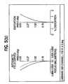
- FIGS. 5 ( a ) and 5 ( b )Some monochromatic performance results for the objective lens of FIG. 1 are illustrated in FIGS. 5 ( a ) and 5 ( b ).
- FIG. 5 ( a )illustrates the Modulation Transfer Function (MTF) plot of the feasibility design for the II channel of the objective lens.
- MTFModulation Transfer Function
- the performance of the feasibility design across the field of view (II tube format)is nearly diffraction limited for all spatial frequencies from the effective Nyquist frequency of the II tube on down.
- the optics-detector combinationis detector limited in this monochromatic design analysis.
- This high level of monochromatic performance in the designestablishes the feasibility of creating high quality imagery while leaving room for achromatizing it over the required spectral band, lens design simplification, fabrication tolerances, and other such tradeoffs.
- the astigmatism and distortion of the II channel lens designare indicated in FIG. 5 ( b ).
- the smooth monotonic nature of the astigmatism curvesindicate that the lens design minimizes field aberration and that there is no higher-order aberration balancing occurring in order to achieve the high level of performance indicated in FIG. 5 ( a ).
- the distortion curveis also monotonic and has a low magnitude out to the edge of the field.
- FIGS. 6 ( a ) and 6 ( b )the lens configuration of the LWIR channel of FIG. 2 is also explored with a monochromatic lens design.
- FIG. 6 ( a )illustrates the MTF plot of the design for the LWIR channel. The performance is very good on axis and over most of the field of view, relative to the diffraction limit, with a fall off at the corner of the detector. Due to the fact that the user will only use the field for acquisition over the scene being viewed and then bring the object of interest to the center of the field of view, this drop off in performance at the corner is not considered a significant detriment in this feasibility design.
- the astigmatism and distortion of the LWIR channel lens designare indicated in FIG. 6 ( b ).
- the smooth nature of the astigmatism curvesindicates that the design does not have higher-order field aberrations.
- the distortion curveis monotonic and has a low magnitude out to the edge of the field. This result indicates that controlling of the distortion of the LWIR channel with respect to the II channel is achievable to a close agreement level between the two channels.
- multiple parametersmay be required and/or considered.
- Basic optical parameters of the multi-band objective lensinclude the effective focal length (EFL) which is preferably between 130 and 200 mm; relative aperture (f/n) which is preferably 1.5 to 1.0 or faster for the IR channel(s); pupil diameter which is, for example, 121 mm for EFL of 170 mm, pupil linear obscuration minimized to between approximately 0.25 and 0.3, wavelength band imaging between 0.6 to 14 ⁇ m, and selection of detectors for both the VIS/NIR, the MWIR, and the LWIR.
- EFLeffective focal length
- f/nrelative aperture
- pupil diameterwhich is, for example, 121 mm for EFL of 170 mm, pupil linear obscuration minimized to between approximately 0.25 and 0.3, wavelength band imaging between 0.6 to 14 ⁇ m, and selection of detectors for both the VIS/NIR, the MWIR, and the LWIR.
- Optical performance parameters which need to be maximized in the lens design of the multiband objective lens besides the imageryinclude reflection/transmission per surface, transmission per lens system, relative illumination uniformity.
- Optical performance parameters that are to be minimizedinclude ghosts, distortion, and any vignetting.
- the sphericity or asphericity of the corrector lens, primary component, and/or secondary componentsis a parameter that may be manipulated. Depending on the intended end-use for the multiple-band imaging device, at least one of these components may be aspheric in order to meet specific optical criteria. Additionally, the use of different materials for the individual lenses comprising the corrector lens and the primary and secondary components, the use of a diffractive optical element (DOE) within the components, as well as the curvatures of the individual lens (e.g., positive, negative) may also be considered in order to optimize optical performance of the objective lens. Further, field lenses to correct for aberrations may also be used.
- DOEdiffractive optical element
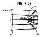
- FIGS. 7 ( a ) through 7 ( d )other possible VIS/NIR optical configurations for this application from the monochromatic performance are shown in FIGS. 7 ( a ) through 7 ( d ). These embodiments vary based on the number and location of aspheric surfaces.
- FIG. 7 ( a )all three major optical components the corrector lens 10 , the primary component 15 , and the secondary component 20 of the objective lens have aspheric surfaces.
- FIG. 7 ( b )the corrector lens 10 and the secondary component 20 have aspheric surfaces.
- FIG. 7 ( c )the corrector lens 10 and the primary component 15 have aspheric surfaces and in FIG. 7 ( d ) only the corrector lens 10 has an aspheric surface.
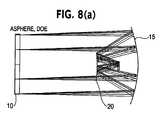
- FIGS. 8 ( a ) through 8 ( f )color-corrected lens design forms for the VIS/NIR band from 600-1,000 nm are presented.
- the primary and secondary components 15 , 20are spherical while the corrector lens 10 is aspheric and includes a DOE.
- the corrector lens 10is comprised of two lenses 11 and 12 , having in order of incoming scene interaction, negative and positive overall power, respectively. All of the components, including the lenses 11 , 12 and the primary and secondary components 15 , 20 are spherical. Further the objective lens in FIG.
- FIG. 8 ( b )includes an aperture stop 21 located approximately midway between the corrector lens group and the primary component 15 .
- the corrector lens 10is comprised of two lenses 11 and 12 , having in order of incoming scene interaction, positive and negative overall power, respectively. All of the components, including the lenses 11 , 12 and the primary and secondary components 15 , 20 are spherical.
- FIG. 8 ( g )illustrates the color-corrected modulation transfer function (“MTF”) performance available to that of lens configuration depicted in FIG. 8 ( e ) for the II channel. As depicted, performance is maximized in the center of the format where the device will be primarily be used.
- MTFcolor-corrected modulation transfer function
- FIG. 8 ( f )illustrates the color-corrected MTF performance available to that of the lens configuration depicted in FIG. 8 ( f ) for the II channel.
- the LWIR band optical performanceis also acceptable using the objective lens configurations of FIGS. 8 ( b ) and 8 ( e ), respectively.
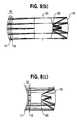
- the three major optical components 10 , 15 , and 20 of the objective lensare all spherical.
- the radiationpasses through the secondary component 20 unlike the VISINIR band, which is reflected by the secondary component 20 .
- the three major optical components 10 , 15 , and 20 of the objective lensare all spherical and the radiation passes through the secondary component 20 .
- FIGS. 9 ( a ) and 9 ( b )the three major optical components 10 , 15 , and 20 of the objective lens are all spherical and the radiation passes through the secondary component 20 .
- FIGS. 10 ( a ) and 10 ( d )the all-spherical objective lens configurations of FIGS. 8 ( b ), 8 ( e ), 9 ( a ), and 9 ( b ) are shown in combination, including the VIS/NIR and LWIR detectors 30 and 40 .
- optical components 7 ( a ) through 10 ( f )are supporting optical components (e.g., aberration correction lenses) (not numbered) for both the VIS/NIR and the LWIR bands.
- These supporting optical componentsneed not be specifically described herein as they are easily understood by those skilled in the art.
- the IR lenses described abovemay be formed from any suitable material (e.g., zinc sulfide, zinc sulfide MS, zinc selenide, germanium) as is commonly understood by those skilled in the art.
- suitable materiale.g., zinc sulfide, zinc sulfide MS, zinc selenide, germanium
- the optical parametersi.e., radius of curvature, index of refraction, diameter, material, etc., of all of the lenses including correction, field, primary, and secondary, used in the embodiments of the present invention are selectable based on the specific design requirements of each imaging system. As such, these particulars will not be discussed further herein.
- the environmental parameters that are met by the preferred embodimentsinclude those applicable to a handheld device used by military personnel, including temperature operational and storage range, shock, vibration, humidity and altitude. Commercial variations of these environmental parameters may be less demanding.
- the housing requirements met by the objective lens of the preferred embodimentsinclude a sealed, protective front element and the capability for back-filling with a dry inert gas.
- Packaging considerations taken into account in designing the preferred objective lenses of the present inventioninclude filters and filter location with the objective system, window location, material, thickness distance from primary component, minimization of the number of elements comprising the objective, number of different optical materials used to compose the objective, types of surfaces (e.g., aspheric), length, diameter, and weight.
- a preferred approach contemplated by this inventionis to move the primary component in relationship to the secondary component, a technique that is used in other catadioptric lens applications. In this manner both wavebands will be adjusted for range.
- a second approachis to move the entire lens in relationship to the II tube and use a follower mechanism (mechanical or electrically driven) for the LWIR section.
- a third approachis to move the field lens(es) in front of the II tube and a follower mechanism in the LWIR optical path.
- selection of materials for the housing and mounting bracketsis made to achieve uniform focus over the range.
- An alternate to housing material selection for uniform focus over full temperature rangeis to use an electronically controlled thermal focus adjustment to compensate for discrepancies between channels when standard housing materials are used.
- a fire fighterequipped with the visible/IR imaging system above, is able to go from daylight into a smoke-filled building and vice versa and maintain some amount of visual contact without ever removing the imaging system or having to switch between multiple imaging systems or components. Further, the firefighter need not choose between visible and IR, but may simultaneously maximize his/her viewing capability by utilizing both views at all times. Other applicable users include all emergency personnel (e.g., police, search & rescue), the military, sportsman (e.g., hunters), ship operators, aircraft operators, and the like. This type of compact imaging system is useful in any situation where there could be a fluctuation or shift from visible to IR viewing conditions and vice versa.
Landscapes
- Physics & Mathematics (AREA)
- General Physics & Mathematics (AREA)
- Optics & Photonics (AREA)
- Spectroscopy & Molecular Physics (AREA)
- Astronomy & Astrophysics (AREA)
- Health & Medical Sciences (AREA)
- Toxicology (AREA)
- Telescopes (AREA)
- Lenses (AREA)
Abstract
Description
Claims (26)
Priority Applications (3)
| Application Number | Priority Date | Filing Date | Title |
|---|---|---|---|
| US09/651,111US6646799B1 (en) | 2000-08-30 | 2000-08-30 | System and method for combining multiple energy bands to improve scene viewing |
| US10/461,376US6909539B2 (en) | 2000-08-30 | 2003-06-16 | System and method for combining multiple energy bands to improve scene viewing |
| US11/124,277US20050205784A1 (en) | 2000-08-30 | 2005-05-09 | System and method for combining multiple energy bands to improve scene viewing |
Applications Claiming Priority (1)
| Application Number | Priority Date | Filing Date | Title |
|---|---|---|---|
| US09/651,111US6646799B1 (en) | 2000-08-30 | 2000-08-30 | System and method for combining multiple energy bands to improve scene viewing |
Related Child Applications (1)
| Application Number | Title | Priority Date | Filing Date |
|---|---|---|---|
| US10/461,376ContinuationUS6909539B2 (en) | 2000-08-30 | 2003-06-16 | System and method for combining multiple energy bands to improve scene viewing |
Publications (1)
| Publication Number | Publication Date |
|---|---|
| US6646799B1true US6646799B1 (en) | 2003-11-11 |
Family
ID=29401781
Family Applications (3)
| Application Number | Title | Priority Date | Filing Date |
|---|---|---|---|
| US09/651,111Expired - LifetimeUS6646799B1 (en) | 2000-08-30 | 2000-08-30 | System and method for combining multiple energy bands to improve scene viewing |
| US10/461,376Expired - LifetimeUS6909539B2 (en) | 2000-08-30 | 2003-06-16 | System and method for combining multiple energy bands to improve scene viewing |
| US11/124,277AbandonedUS20050205784A1 (en) | 2000-08-30 | 2005-05-09 | System and method for combining multiple energy bands to improve scene viewing |
Family Applications After (2)
| Application Number | Title | Priority Date | Filing Date |
|---|---|---|---|
| US10/461,376Expired - LifetimeUS6909539B2 (en) | 2000-08-30 | 2003-06-16 | System and method for combining multiple energy bands to improve scene viewing |
| US11/124,277AbandonedUS20050205784A1 (en) | 2000-08-30 | 2005-05-09 | System and method for combining multiple energy bands to improve scene viewing |
Country Status (1)
| Country | Link |
|---|---|
| US (3) | US6646799B1 (en) |
Cited By (32)
| Publication number | Priority date | Publication date | Assignee | Title |
|---|---|---|---|---|
| US20020030163A1 (en)* | 2000-08-09 | 2002-03-14 | Zhang Evan Y.W. | Image intensifier and LWIR fusion/combination system |
| US20030218801A1 (en)* | 2000-08-30 | 2003-11-27 | Korniski Ronald James | System and method for combining multiple energy bands to improve scene viewing |
| US20040104346A1 (en)* | 2002-11-08 | 2004-06-03 | Devitt John W. | Methods and systems for distinguishing multiple wavelengths of radiation in a detection system |
| US20040125443A1 (en)* | 2001-11-19 | 2004-07-01 | Hideaki Nakajima | Binocular device |
| US20040135881A1 (en)* | 2002-07-26 | 2004-07-15 | Jones Peter W.J. | Methods for visually separating an object from its background, methods for detecting a camouflaged object against its background and detection apparatus embodying such methods |
| US6798578B1 (en)* | 2002-06-06 | 2004-09-28 | Litton Systems, Inc. | Integrated display image intensifier assembly |
| US20040256558A1 (en)* | 2003-06-07 | 2004-12-23 | Gunter Kuerbitz | System and method for generating three-dimensional image displays |
| US20050162514A1 (en)* | 2003-06-30 | 2005-07-28 | Dennis Michael R. | Plural-receptor, plural-mode, surveillance imaging system and methodology with task-minimizing, view-establishment control |
| US20050206727A1 (en)* | 2000-10-13 | 2005-09-22 | L-3 Communications Corporation | System and method for forming images for display in a vehicle |
| US20060043296A1 (en)* | 2004-08-24 | 2006-03-02 | Mian Zahid F | Non-visible radiation imaging and inspection |
| WO2007022521A3 (en)* | 2005-08-19 | 2007-05-03 | Itt Mfg Enterprises Inc | Ganged focus mechanism for an optical device |
| US20070222854A1 (en)* | 2006-03-24 | 2007-09-27 | Omnitech Partners | Image combining viewer |
| WO2007107975A1 (en)* | 2006-03-20 | 2007-09-27 | Itl Optronics Ltd. | Optical distance viewing device having positioning and/or map display facilities |
| US20070235634A1 (en)* | 2004-07-02 | 2007-10-11 | Ottney Joseph C | Fusion night vision system |
| US20080006772A1 (en)* | 2006-07-05 | 2008-01-10 | Honeywell International Inc. | Thermally-directed optical processing |
| US7333270B1 (en) | 2005-06-10 | 2008-02-19 | Omnitech Partners | Dual band night vision device |
| US20080204702A1 (en)* | 2007-02-12 | 2008-08-28 | Stefan Gerth | Optical observation apparatus |
| FR2913778A1 (en)* | 2007-03-16 | 2008-09-19 | Thales Sa | Afocal optical device for use in front of e.g. night vision binocular body, has lens assembly forming image from another image at infinity, where former image is in same direction as luminous object, exit pupil and input pupil image |
| EP2053444A1 (en)* | 2007-10-22 | 2009-04-29 | Wings Aktiebolag | Optical system |
| US20090193704A1 (en)* | 2004-12-14 | 2009-08-06 | Eugene Pochapsky | Night sight and method of making the same |
| US20110002505A1 (en)* | 2009-07-02 | 2011-01-06 | Barrow William H | System and Method For Analysis of Image Data |
| CN102589710A (en)* | 2012-02-09 | 2012-07-18 | 北京空间机电研究所 | Optical imaging system of bispectrum space low temperature thermal imager |
| WO2012103879A1 (en)* | 2011-02-04 | 2012-08-09 | Eads Deutschland Gmbh | Camera system and method for observing objects at great distances, in particular for monitoring target objects at night, in mist, dust or rain |
| US20130250123A1 (en)* | 2011-11-04 | 2013-09-26 | Qualcomm Incorporated | Multispectral imaging system |
| CN103926010A (en)* | 2014-04-18 | 2014-07-16 | 山东神戎电子股份有限公司 | Multifunctional dual-spectrum portable observation instrument |
| US20170078591A1 (en)* | 2015-09-11 | 2017-03-16 | Gsci | Multi-modal optoelectronic vision system and uses thereof |
| US9948914B1 (en) | 2015-05-06 | 2018-04-17 | The United States Of America As Represented By The Secretary Of The Air Force | Orthoscopic fusion platform |
| US10126099B1 (en) | 2017-05-11 | 2018-11-13 | Steiner Eoptics, Inc. | Thermal reflex sight |
| CN109827660A (en)* | 2019-02-28 | 2019-05-31 | 温州大学 | A Multi-band Separation Low-light Enhancement Method |
| RU2711628C1 (en)* | 2019-04-02 | 2020-01-17 | Публичное Акционерное общество "Ростовский оптико-механический завод" (ПАО РОМЗ) | Night vision goggles |
| RU2754887C1 (en)* | 2020-10-12 | 2021-09-08 | Александр Владимирович Медведев | Night vision goggles for pilot |
| WO2024036512A1 (en)* | 2022-08-17 | 2024-02-22 | 烟台艾睿光电科技有限公司 | Three-light binoculars |
Families Citing this family (49)
| Publication number | Priority date | Publication date | Assignee | Title |
|---|---|---|---|---|
| US7453552B1 (en)* | 2004-07-16 | 2008-11-18 | Lockheed Martin Corporation | Laser amplification methods and apparatuses |
| DE102005006290A1 (en)* | 2005-02-11 | 2006-08-24 | Bayerische Motoren Werke Ag | Method and device for visualizing the surroundings of a vehicle by fusion of an infrared and a visual image |
| US20100243891A1 (en)* | 2005-06-15 | 2010-09-30 | Timothy Day | Compact mid-ir laser |
| US7492806B2 (en) | 2005-06-15 | 2009-02-17 | Daylight Solutions, Inc. | Compact mid-IR laser |
| US7535656B2 (en) | 2005-06-15 | 2009-05-19 | Daylight Solutions, Inc. | Lenses, optical sources, and their couplings |
| US7911687B2 (en)* | 2005-08-04 | 2011-03-22 | Raytheon Company | Sighted device operable in visible-wavelength or electro-optical/visible-wavelength sighting modes |
| US7848382B2 (en) | 2008-01-17 | 2010-12-07 | Daylight Solutions, Inc. | Laser source that generates a plurality of alternative wavelength output beams |
| GB0807487D0 (en)* | 2008-04-24 | 2008-12-31 | Selex Sensors & Airborne Sys | Infra Red Dectector System and Method |
| US8565275B2 (en) | 2008-04-29 | 2013-10-22 | Daylight Solutions, Inc. | Multi-wavelength high output laser source assembly with precision output beam |
| US8774244B2 (en) | 2009-04-21 | 2014-07-08 | Daylight Solutions, Inc. | Thermal pointer |
| US9557456B2 (en) | 2010-01-29 | 2017-01-31 | The United States Of America As Represented By The Secretary Of The Army | Broadband optics for manipulating light beams and images |
| US11366254B2 (en) | 2010-01-29 | 2022-06-21 | Beam Engineering For Advanced Measurements Co. | High-efficiency wide-angle beam steering system |
| US8718105B2 (en)* | 2010-03-15 | 2014-05-06 | Daylight Solutions, Inc. | Laser source that generates a rapidly changing output beam |
| US10197715B1 (en) | 2013-03-15 | 2019-02-05 | Beam Engineering For Advanced Measurements Co. | Methods of diffractive lens and mirror fabrication |
| US9983479B2 (en) | 2010-04-21 | 2018-05-29 | Beam Engineering For Advanced Measurements Co. | Fabrication of high efficiency, high quality, large area diffractive waveplates and arrays |
| US10114239B2 (en) | 2010-04-21 | 2018-10-30 | Beam Engineering For Advanced Measurements Co. | Waveplate lenses and methods for their fabrication |
| US20110262844A1 (en) | 2010-04-21 | 2011-10-27 | Beam Engineering For Advanced Measurement Co. | Fabrication of high efficiency, high quality, large area diffractive waveplates and arrays |
| US8335413B2 (en) | 2010-05-14 | 2012-12-18 | Daylight Solutions, Inc. | Optical switch |
| US9225148B2 (en) | 2010-09-23 | 2015-12-29 | Daylight Solutions, Inc. | Laser source assembly with thermal control and mechanically stable mounting |
| US8467430B2 (en) | 2010-09-23 | 2013-06-18 | Daylight Solutions, Inc. | Continuous wavelength tunable laser source with optimum orientation of grating and gain medium |
| US9042688B2 (en) | 2011-01-26 | 2015-05-26 | Daylight Solutions, Inc. | Multiple port, multiple state optical switch |
| US8867128B2 (en)* | 2011-02-04 | 2014-10-21 | N-Vision Optics, Llc | Binocular system |
| US20130083199A1 (en)* | 2011-10-04 | 2013-04-04 | Fluke Corporation | Thermal imaging camera with infrared lens focus adjustment |
| JP2013218022A (en)* | 2012-04-05 | 2013-10-24 | Olympus Imaging Corp | Reflection telephoto optical system, optical unit, and imaging apparatus having the same |
| US10107945B2 (en) | 2013-03-01 | 2018-10-23 | Beam Engineering For Advanced Measurements Co. | Vector vortex waveplates |
| US10185182B2 (en)* | 2013-03-03 | 2019-01-22 | Beam Engineering For Advanced Measurements Co. | Mechanical rubbing method for fabricating cycloidal diffractive waveplates |
| USD721123S1 (en) | 2013-07-19 | 2015-01-13 | N-Vision Optics, Llc | Optics mount |
| USD721122S1 (en) | 2013-07-19 | 2015-01-13 | N-Vision Optics, Llc | Optics mount |
| CN103645554A (en)* | 2013-10-28 | 2014-03-19 | 中国科学院长春光学精密机械与物理研究所 | Refraction and reflection type infrared imaging system |
| CA2946693A1 (en) | 2014-04-16 | 2015-10-22 | David E. Roberts | Methods and apparatus for human vision correction using diffractive waveplate lenses |
| US10330947B2 (en)* | 2015-06-22 | 2019-06-25 | Beam Engineering For Advanced Measurements, Co. | Diffractive mirrors and diffractive telescopes with corrected temporal dispersion |
| US9976911B1 (en) | 2015-06-30 | 2018-05-22 | Beam Engineering For Advanced Measurements Co. | Full characterization wavefront sensor |
| US10191296B1 (en) | 2015-06-30 | 2019-01-29 | Beam Engineering For Advanced Measurements Co. | Laser pointer with reduced risk of eye injury |
| US10436957B2 (en) | 2015-10-27 | 2019-10-08 | Beam Engineering For Advanced Measurements Co. | Broadband imaging with diffractive waveplate coated mirrors and diffractive waveplate objective lens |
| US10075646B2 (en) | 2015-11-30 | 2018-09-11 | Sensors Unlimited, Inc. | Sensor systems and methods |
| CN106324817A (en)* | 2016-06-22 | 2017-01-11 | 上海航天控制技术研究所 | Compact optical system |
| US10423045B2 (en) | 2016-11-14 | 2019-09-24 | Beam Engineering For Advanced Measurements Co. | Electro-optical diffractive waveplate beam shaping system |
| US10274805B2 (en) | 2017-06-13 | 2019-04-30 | Beam Engineering For Advanced Measurements Co. | Polarization-independent switchable lens system |
| US11175441B1 (en) | 2018-03-05 | 2021-11-16 | Beam Engineering For Advanced Measurements Co. | Polarization-independent diffractive optical structures |
| US11982906B1 (en) | 2018-03-05 | 2024-05-14 | Beam Engineering For Advanced Measurements Co. | Polarization-independent diffractive optical structures |
| US10896492B2 (en) | 2018-11-09 | 2021-01-19 | Qwake Technologies, Llc | Cognitive load reducing platform having image edge enhancement |
| US11890494B2 (en) | 2018-11-09 | 2024-02-06 | Qwake Technologies, Inc. | Retrofittable mask mount system for cognitive load reducing platform |
| US10417497B1 (en) | 2018-11-09 | 2019-09-17 | Qwake Technologies | Cognitive load reducing platform for first responders |
| US11294240B2 (en) | 2019-08-10 | 2022-04-05 | Beam Engineering For Advanced Measurements Co. | Diffractive waveplate devices that operate over a wide temperature range |
| US11915376B2 (en) | 2019-08-28 | 2024-02-27 | Qwake Technologies, Inc. | Wearable assisted perception module for navigation and communication in hazardous environments |
| CN110927940B (en)* | 2019-12-19 | 2022-02-08 | 浙江舜宇光学有限公司 | Image pickup apparatus |
| US11431921B2 (en) | 2020-01-06 | 2022-08-30 | Raytheon Company | Mm-wave short flat-field Schmidt imager using one or more diffraction grating(s) and/or Fresnel lens(s) |
| US20210255444A1 (en)* | 2020-02-18 | 2021-08-19 | Raytheon Company | Lightweight modified-schmidt corrector lens |
| DE102022114813B3 (en)* | 2022-06-13 | 2023-07-06 | Carl Zeiss Ag | Optical arrangement with overview function for catadioptric microscope objective, objective, image acquisition device or image reproduction device and device |
Citations (13)
| Publication number | Priority date | Publication date | Assignee | Title |
|---|---|---|---|---|
| US3745347A (en)* | 1970-12-03 | 1973-07-10 | Philips Corp | Telescope including an imaging system for radiation in the visible range |
| US5373182A (en) | 1993-01-12 | 1994-12-13 | Santa Barbara Research Center | Integrated IR and visible detector |
| US5432374A (en) | 1993-02-08 | 1995-07-11 | Santa Barbara Research Center | Integrated IR and mm-wave detector |
| US5729016A (en) | 1994-04-12 | 1998-03-17 | Hughes Aircraft Company | Low cost night vision system for nonmilitary surface vehicles |
| US5808350A (en) | 1997-01-03 | 1998-09-15 | Raytheon Company | Integrated IR, visible and NIR sensor and methods of fabricating same |
| US5880888A (en) | 1989-01-23 | 1999-03-09 | Hughes Aircraft Company | Helmet mounted display system |
| US5907150A (en) | 1997-07-28 | 1999-05-25 | Saldana; Michael R. | Multi-function day/night observation, ranging, and sighting device and method of its operation |
| US5909244A (en) | 1996-04-15 | 1999-06-01 | Massachusetts Institute Of Technology | Real time adaptive digital image processing for dynamic range remapping of imagery including low-light-level visible imagery |
| US5933277A (en) | 1998-05-29 | 1999-08-03 | General Motors Corporation | Imaging system combining visible and non-visible electromagnetic radiation for enhanced vision |
| US5943174A (en) | 1998-06-16 | 1999-08-24 | Itt Manufacturing Enterprises, Inc. | Night vision monocular device |
| US6061182A (en) | 1996-11-21 | 2000-05-09 | Vectop Ltd. | Combiner for superimposing a display image on to an image of an external scene |
| US6204961B1 (en)* | 1995-09-18 | 2001-03-20 | Litton Systems, Inc. | Day and night sighting system |
| US6366399B1 (en)* | 1998-05-15 | 2002-04-02 | Pilkington P.E. Limited | Optical imaging system |
Family Cites Families (8)
| Publication number | Priority date | Publication date | Assignee | Title |
|---|---|---|---|---|
| US3524698A (en)* | 1967-12-08 | 1970-08-18 | Tridea Electronics | Anastigmatic wide-field cassegrain system |
| US3614209A (en)* | 1970-02-24 | 1971-10-19 | Chrysler Corp | Wide angle-biocular eyepiece |
| US4486069A (en)* | 1981-07-01 | 1984-12-04 | Barr & Stroud Limited | Afocal telescopes |
| GB2152227B (en)* | 1982-01-14 | 1986-01-29 | Barr & Stroud Ltd | Infrared optical system |
| US4989962A (en)* | 1988-10-31 | 1991-02-05 | Hughes Aircraft Company | Dual band/dual FOV infrared telescope |
| US5204774A (en)* | 1991-12-06 | 1993-04-20 | Varo Inc. | Night vision goggle with improved optical system |
| US5528418A (en)* | 1993-11-30 | 1996-06-18 | The United States Of America As Represented By The Secretary Of The Navy | Night augmented day scope |
| US6646799B1 (en)* | 2000-08-30 | 2003-11-11 | Science Applications International Corporation | System and method for combining multiple energy bands to improve scene viewing |
- 2000
- 2000-08-30USUS09/651,111patent/US6646799B1/ennot_activeExpired - Lifetime
- 2003
- 2003-06-16USUS10/461,376patent/US6909539B2/ennot_activeExpired - Lifetime
- 2005
- 2005-05-09USUS11/124,277patent/US20050205784A1/ennot_activeAbandoned
Patent Citations (13)
| Publication number | Priority date | Publication date | Assignee | Title |
|---|---|---|---|---|
| US3745347A (en)* | 1970-12-03 | 1973-07-10 | Philips Corp | Telescope including an imaging system for radiation in the visible range |
| US5880888A (en) | 1989-01-23 | 1999-03-09 | Hughes Aircraft Company | Helmet mounted display system |
| US5373182A (en) | 1993-01-12 | 1994-12-13 | Santa Barbara Research Center | Integrated IR and visible detector |
| US5432374A (en) | 1993-02-08 | 1995-07-11 | Santa Barbara Research Center | Integrated IR and mm-wave detector |
| US5729016A (en) | 1994-04-12 | 1998-03-17 | Hughes Aircraft Company | Low cost night vision system for nonmilitary surface vehicles |
| US6204961B1 (en)* | 1995-09-18 | 2001-03-20 | Litton Systems, Inc. | Day and night sighting system |
| US5909244A (en) | 1996-04-15 | 1999-06-01 | Massachusetts Institute Of Technology | Real time adaptive digital image processing for dynamic range remapping of imagery including low-light-level visible imagery |
| US6061182A (en) | 1996-11-21 | 2000-05-09 | Vectop Ltd. | Combiner for superimposing a display image on to an image of an external scene |
| US5808350A (en) | 1997-01-03 | 1998-09-15 | Raytheon Company | Integrated IR, visible and NIR sensor and methods of fabricating same |
| US5907150A (en) | 1997-07-28 | 1999-05-25 | Saldana; Michael R. | Multi-function day/night observation, ranging, and sighting device and method of its operation |
| US6366399B1 (en)* | 1998-05-15 | 2002-04-02 | Pilkington P.E. Limited | Optical imaging system |
| US5933277A (en) | 1998-05-29 | 1999-08-03 | General Motors Corporation | Imaging system combining visible and non-visible electromagnetic radiation for enhanced vision |
| US5943174A (en) | 1998-06-16 | 1999-08-24 | Itt Manufacturing Enterprises, Inc. | Night vision monocular device |
Non-Patent Citations (4)
| Title |
|---|
| Fallon, M., "Infrared and Visible Imaging Combined in One Camera", Photonics Spectra, Dec. 2001, pp. 119-121. |
| Handley, R., "Multispectral and Thermal Imaging", www.advancedimagingmag.com, Mar. 2001, pg. 45. |
| Lareau, A. G., "Tactical Airborne Reconnaissance Goes Dual-Band and Beyond", Photonics Spectra, Jul. 2002, pp. 64-68. |
| Scribner, D., Schuler, J., Warren, P., Howard, G., Klein, R., "Melding Images for Information", Spie's OE Magazine, Sep. 2002, pp. 24-26. |
Cited By (55)
| Publication number | Priority date | Publication date | Assignee | Title |
|---|---|---|---|---|
| US7345277B2 (en)* | 2000-08-09 | 2008-03-18 | Evan Zhang | Image intensifier and LWIR fusion/combination system |
| US20020030163A1 (en)* | 2000-08-09 | 2002-03-14 | Zhang Evan Y.W. | Image intensifier and LWIR fusion/combination system |
| US6909539B2 (en)* | 2000-08-30 | 2005-06-21 | Science Applications International Corporation | System and method for combining multiple energy bands to improve scene viewing |
| US20050205784A1 (en)* | 2000-08-30 | 2005-09-22 | Science Applications International Corporation | System and method for combining multiple energy bands to improve scene viewing |
| US20030218801A1 (en)* | 2000-08-30 | 2003-11-27 | Korniski Ronald James | System and method for combining multiple energy bands to improve scene viewing |
| US7227515B2 (en)* | 2000-10-13 | 2007-06-05 | L-3 Communications Corporation | System and method for forming images for display in a vehicle |
| US20050206727A1 (en)* | 2000-10-13 | 2005-09-22 | L-3 Communications Corporation | System and method for forming images for display in a vehicle |
| US20040125443A1 (en)* | 2001-11-19 | 2004-07-01 | Hideaki Nakajima | Binocular device |
| US6924932B2 (en)* | 2001-11-19 | 2005-08-02 | Hideaki Nakajima | Binocular device |
| US20040196566A1 (en)* | 2002-06-06 | 2004-10-07 | Litton Systems, Inc. | Integrated display image intensifier assembly |
| US6798578B1 (en)* | 2002-06-06 | 2004-09-28 | Litton Systems, Inc. | Integrated display image intensifier assembly |
| US7929727B2 (en)* | 2002-07-26 | 2011-04-19 | Tenebraex Corporation | Methods for visually separating an object from its background, methods for detecting a camouflaged object against its background and detection apparatus embodying such methods |
| US20040135881A1 (en)* | 2002-07-26 | 2004-07-15 | Jones Peter W.J. | Methods for visually separating an object from its background, methods for detecting a camouflaged object against its background and detection apparatus embodying such methods |
| US7351977B2 (en)* | 2002-11-08 | 2008-04-01 | L-3 Communications Cincinnati Electronics Corporation | Methods and systems for distinguishing multiple wavelengths of radiation and increasing detected signals in a detection system using micro-optic structures |
| US20040104346A1 (en)* | 2002-11-08 | 2004-06-03 | Devitt John W. | Methods and systems for distinguishing multiple wavelengths of radiation in a detection system |
| US20040256558A1 (en)* | 2003-06-07 | 2004-12-23 | Gunter Kuerbitz | System and method for generating three-dimensional image displays |
| US7098458B2 (en)* | 2003-06-07 | 2006-08-29 | Zeiss Optronik Gmbh | System and method for generating three-dimensional image displays |
| US20050162514A1 (en)* | 2003-06-30 | 2005-07-28 | Dennis Michael R. | Plural-receptor, plural-mode, surveillance imaging system and methodology with task-minimizing, view-establishment control |
| US7307793B2 (en) | 2004-07-02 | 2007-12-11 | Insight Technology, Inc. | Fusion night vision system |
| US20070235634A1 (en)* | 2004-07-02 | 2007-10-11 | Ottney Joseph C | Fusion night vision system |
| US7208733B2 (en)* | 2004-08-24 | 2007-04-24 | International Electronic Machines Corp. | Non-visible radiation imaging and inspection |
| US20060043296A1 (en)* | 2004-08-24 | 2006-03-02 | Mian Zahid F | Non-visible radiation imaging and inspection |
| US20090193704A1 (en)* | 2004-12-14 | 2009-08-06 | Eugene Pochapsky | Night sight and method of making the same |
| US7827727B2 (en) | 2004-12-14 | 2010-11-09 | Omnitech Partners | Night sight and method of making the same |
| US20110113671A1 (en)* | 2004-12-14 | 2011-05-19 | Pochapsky Eugene J | Night sight and method of making the same |
| US20080297885A1 (en)* | 2005-06-10 | 2008-12-04 | Eugene Pochapsky | Dual band night vision device |
| US7333270B1 (en) | 2005-06-10 | 2008-02-19 | Omnitech Partners | Dual band night vision device |
| WO2007022521A3 (en)* | 2005-08-19 | 2007-05-03 | Itt Mfg Enterprises Inc | Ganged focus mechanism for an optical device |
| WO2007107975A1 (en)* | 2006-03-20 | 2007-09-27 | Itl Optronics Ltd. | Optical distance viewing device having positioning and/or map display facilities |
| US20090306892A1 (en)* | 2006-03-20 | 2009-12-10 | Itl Optronics Ltd. | Optical distance viewing device having positioning and/or map display facilities |
| US7483213B2 (en) | 2006-03-24 | 2009-01-27 | Omnitech Partners | Image combining viewer |
| US20070222854A1 (en)* | 2006-03-24 | 2007-09-27 | Omnitech Partners | Image combining viewer |
| US7491935B2 (en) | 2006-07-05 | 2009-02-17 | Honeywell International Inc. | Thermally-directed optical processing |
| US20080006772A1 (en)* | 2006-07-05 | 2008-01-10 | Honeywell International Inc. | Thermally-directed optical processing |
| US20080204702A1 (en)* | 2007-02-12 | 2008-08-28 | Stefan Gerth | Optical observation apparatus |
| US7869004B2 (en)* | 2007-02-12 | 2011-01-11 | Carl Zeiss Sports Optics Gmbh | Optical observation apparatus |
| FR2913778A1 (en)* | 2007-03-16 | 2008-09-19 | Thales Sa | Afocal optical device for use in front of e.g. night vision binocular body, has lens assembly forming image from another image at infinity, where former image is in same direction as luminous object, exit pupil and input pupil image |
| EP2053444A1 (en)* | 2007-10-22 | 2009-04-29 | Wings Aktiebolag | Optical system |
| US8265338B2 (en)* | 2009-07-02 | 2012-09-11 | Lockheed Martin Corporation | System and method for analysis of image data |
| US20110002505A1 (en)* | 2009-07-02 | 2011-01-06 | Barrow William H | System and Method For Analysis of Image Data |
| DE102011010334B4 (en)* | 2011-02-04 | 2014-08-28 | Eads Deutschland Gmbh | Camera system and method for observing objects at a great distance, in particular for monitoring target objects at night, mist, dust or rain |
| CN103477278A (en)* | 2011-02-04 | 2013-12-25 | 伊德斯德国股份有限公司 | Camera system and method for observing objects at long distances, especially for monitoring target objects at night, in smoke, dust or rain |
| WO2012103879A1 (en)* | 2011-02-04 | 2012-08-09 | Eads Deutschland Gmbh | Camera system and method for observing objects at great distances, in particular for monitoring target objects at night, in mist, dust or rain |
| US9692991B2 (en)* | 2011-11-04 | 2017-06-27 | Qualcomm Incorporated | Multispectral imaging system |
| US20130250123A1 (en)* | 2011-11-04 | 2013-09-26 | Qualcomm Incorporated | Multispectral imaging system |
| CN102589710A (en)* | 2012-02-09 | 2012-07-18 | 北京空间机电研究所 | Optical imaging system of bispectrum space low temperature thermal imager |
| CN103926010A (en)* | 2014-04-18 | 2014-07-16 | 山东神戎电子股份有限公司 | Multifunctional dual-spectrum portable observation instrument |
| US9948914B1 (en) | 2015-05-06 | 2018-04-17 | The United States Of America As Represented By The Secretary Of The Air Force | Orthoscopic fusion platform |
| US9648255B2 (en)* | 2015-09-11 | 2017-05-09 | General Starlight Co., Inc. | Multi-modal optoelectronic vision system and uses thereof |
| US20170078591A1 (en)* | 2015-09-11 | 2017-03-16 | Gsci | Multi-modal optoelectronic vision system and uses thereof |
| US10126099B1 (en) | 2017-05-11 | 2018-11-13 | Steiner Eoptics, Inc. | Thermal reflex sight |
| CN109827660A (en)* | 2019-02-28 | 2019-05-31 | 温州大学 | A Multi-band Separation Low-light Enhancement Method |
| RU2711628C1 (en)* | 2019-04-02 | 2020-01-17 | Публичное Акционерное общество "Ростовский оптико-механический завод" (ПАО РОМЗ) | Night vision goggles |
| RU2754887C1 (en)* | 2020-10-12 | 2021-09-08 | Александр Владимирович Медведев | Night vision goggles for pilot |
| WO2024036512A1 (en)* | 2022-08-17 | 2024-02-22 | 烟台艾睿光电科技有限公司 | Three-light binoculars |
Also Published As
| Publication number | Publication date |
|---|---|
| US20030218801A1 (en) | 2003-11-27 |
| US6909539B2 (en) | 2005-06-21 |
| US20050205784A1 (en) | 2005-09-22 |
Similar Documents
| Publication | Publication Date | Title |
|---|---|---|
| US6646799B1 (en) | System and method for combining multiple energy bands to improve scene viewing | |
| US7842921B2 (en) | Clip-on infrared imager | |
| US7483213B2 (en) | Image combining viewer | |
| CA2304767C (en) | Integrated multifunctional multispectral sight assembly and method | |
| US5035472A (en) | Integrated multispectral man portable weapon sight | |
| JP4108749B2 (en) | Day and night aiming device | |
| US9593945B2 (en) | Optical configuration for a compact integrated day/night viewing and laser range finding system | |
| US20120007987A1 (en) | Optical system with automatic switching between operation in daylight and thermovision modes | |
| US4621888A (en) | Coaxial wideband refractive optical system | |
| US20120019700A1 (en) | Optical system with automatic mixing of daylight and thermal vision digital video signals | |
| US5847879A (en) | Dual wavelength wide angle large reflective unobscured system | |
| EP0766112B1 (en) | Panoramic optics assembly having an initial flat reflective element | |
| US20110315878A1 (en) | Simultaneous dual band dual fov imaging system | |
| US9110276B2 (en) | Full-field GEO imager optics with extended spectral coverage | |
| US10054395B1 (en) | Multi-spectral optical system, multi-spectral weapon sight and weapon sight system | |
| WO2004064391A1 (en) | Versatile camera for various visibility conditions | |
| IL270713A (en) | Two-color inverse telephoto refractive optical form with external pupil for cold shielding | |
| Zhang et al. | Pixel-by-pixel VIS/NIR and LIR sensor fusion system | |
| Bodkin et al. | Compact multi-band (VIS/IR) zoom imager for high resolution long range surveillance | |
| Bergeron et al. | Dual-band dual field-of-view TVWS prototype | |
| CN209784643U (en) | Short wave infrared lens | |
| Zhou | Synthesized night vision goggle | |
| Lloyd-Hart et al. | Final review of adaptive optics results from the preconversion MMT |
Legal Events
| Date | Code | Title | Description |
|---|---|---|---|
| AS | Assignment | Owner name:SCIENCE APPLICATIONS INTERNATIONAL CORP., CALIFORN Free format text:ASSIGNMENT OF ASSIGNORS INTEREST;ASSIGNORS:KORNISKI, RONALD JAMES;DYER, WILLIAM HENRY;REEL/FRAME:011315/0891;SIGNING DATES FROM 20000824 TO 20000825 | |
| STCF | Information on status: patent grant | Free format text:PATENTED CASE | |
| FPAY | Fee payment | Year of fee payment:4 | |
| FPAY | Fee payment | Year of fee payment:8 | |
| AS | Assignment | Owner name:LEIDOS, INC., VIRGINIA Free format text:CHANGE OF NAME;ASSIGNOR:SCIENCE APPLICATIONS INTERNATIONAL CORPORATION;REEL/FRAME:032642/0439 Effective date:20130927 | |
| FPAY | Fee payment | Year of fee payment:12 | |
| SULP | Surcharge for late payment | Year of fee payment:11 | |
| AS | Assignment | Owner name:CITIBANK, N.A., DELAWARE Free format text:SECURITY INTEREST;ASSIGNOR:LEIDOS, INC.;REEL/FRAME:039809/0801 Effective date:20160816 Owner name:CITIBANK, N.A., DELAWARE Free format text:SECURITY INTEREST;ASSIGNOR:LEIDOS, INC.;REEL/FRAME:039818/0272 Effective date:20160816 | |
| AS | Assignment | Owner name:LEIDOS, INC., VIRGINIA Free format text:RELEASE BY SECURED PARTY;ASSIGNOR:CITIBANK, N.A., AS COLLATERAL AGENT;REEL/FRAME:051632/0819 Effective date:20200117 Owner name:LEIDOS, INC., VIRGINIA Free format text:RELEASE BY SECURED PARTY;ASSIGNOR:CITIBANK, N.A., AS COLLATERAL AGENT;REEL/FRAME:051632/0742 Effective date:20200117 |