US6645670B2 - Efficient cell stack for cells with double current collectors sandwich cathodes - Google Patents
Efficient cell stack for cells with double current collectors sandwich cathodesDownload PDFInfo
- Publication number
- US6645670B2 US6645670B2US09/845,875US84587501AUS6645670B2US 6645670 B2US6645670 B2US 6645670B2US 84587501 AUS84587501 AUS 84587501AUS 6645670 B2US6645670 B2US 6645670B2
- Authority
- US
- United States
- Prior art keywords
- cathode
- cathode active
- active material
- vanadium oxide
- current collector
- Prior art date
- Legal status (The legal status is an assumption and is not a legal conclusion. Google has not performed a legal analysis and makes no representation as to the accuracy of the status listed.)
- Expired - Lifetime, expires
Links
- 229910052744lithiumInorganic materials0.000claimsabstractdescription20
- WHXSMMKQMYFTQS-UHFFFAOYSA-NLithiumChemical compound[Li]WHXSMMKQMYFTQS-UHFFFAOYSA-N0.000claimsabstractdescription19
- 239000006182cathode active materialSubstances0.000claimsdescription110
- NUJOXMJBOLGQSY-UHFFFAOYSA-Nmanganese dioxideChemical compoundO=[Mn]=ONUJOXMJBOLGQSY-UHFFFAOYSA-N0.000claimsdescription44
- RAVDHKVWJUPFPT-UHFFFAOYSA-Nsilver;oxido(dioxo)vanadiumChemical compound[Ag+].[O-][V](=O)=ORAVDHKVWJUPFPT-UHFFFAOYSA-N0.000claimsdescription43
- 239000000203mixtureSubstances0.000claimsdescription25
- QPLDLSVMHZLSFG-UHFFFAOYSA-NCopper oxideChemical compound[Cu]=OQPLDLSVMHZLSFG-UHFFFAOYSA-N0.000claimsdescription14
- PXHVJJICTQNCMI-UHFFFAOYSA-NNickelChemical compound[Ni]PXHVJJICTQNCMI-UHFFFAOYSA-N0.000claimsdescription14
- -1cyclic esterChemical class0.000claimsdescription13
- 239000002904solventSubstances0.000claimsdescription13
- GNTDGMZSJNCJKK-UHFFFAOYSA-Ndivanadium pentaoxideChemical compoundO=[V](=O)O[V](=O)=OGNTDGMZSJNCJKK-UHFFFAOYSA-N0.000claimsdescription10
- 239000003792electrolyteSubstances0.000claimsdescription10
- XTHFKEDIFFGKHM-UHFFFAOYSA-NDimethoxyethaneChemical compoundCOCCOCXTHFKEDIFFGKHM-UHFFFAOYSA-N0.000claimsdescription9
- RTAQQCXQSZGOHL-UHFFFAOYSA-NTitaniumChemical compound[Ti]RTAQQCXQSZGOHL-UHFFFAOYSA-N0.000claimsdescription9
- 229910052783alkali metalInorganic materials0.000claimsdescription9
- 239000010936titaniumSubstances0.000claimsdescription9
- OKTJSMMVPCPJKN-UHFFFAOYSA-NCarbonChemical compound[C]OKTJSMMVPCPJKN-UHFFFAOYSA-N0.000claimsdescription8
- BASFCYQUMIYNBI-UHFFFAOYSA-NplatinumChemical compound[Pt]BASFCYQUMIYNBI-UHFFFAOYSA-N0.000claimsdescription8
- 229910052719titaniumInorganic materials0.000claimsdescription8
- 229910045601alloyInorganic materials0.000claimsdescription7
- 239000000956alloySubstances0.000claimsdescription7
- 229910000108silver(I,III) oxideInorganic materials0.000claimsdescription7
- WEVYAHXRMPXWCK-UHFFFAOYSA-NAcetonitrileChemical compoundCC#NWEVYAHXRMPXWCK-UHFFFAOYSA-N0.000claimsdescription6
- ZMXDDKWLCZADIW-UHFFFAOYSA-NN,N-DimethylformamideChemical compoundCN(C)C=OZMXDDKWLCZADIW-UHFFFAOYSA-N0.000claimsdescription6
- SECXISVLQFMRJM-UHFFFAOYSA-NN-MethylpyrrolidoneChemical compoundCN1CCCC1=OSECXISVLQFMRJM-UHFFFAOYSA-N0.000claimsdescription6
- WYURNTSHIVDZCO-UHFFFAOYSA-NTetrahydrofuranChemical compoundC1CCOC1WYURNTSHIVDZCO-UHFFFAOYSA-N0.000claimsdescription6
- YALCWJZSJOMTCG-UHFFFAOYSA-N[O--].[O--].[O--].[O--].[V+5].[Cu++].[Ag+]Chemical compound[O--].[O--].[O--].[O--].[V+5].[Cu++].[Ag+]YALCWJZSJOMTCG-UHFFFAOYSA-N0.000claimsdescription6
- 150000001340alkali metalsChemical class0.000claimsdescription6
- 229910052759nickelInorganic materials0.000claimsdescription6
- 239000005751Copper oxideSubstances0.000claimsdescription5
- 229910032387LiCoO2Inorganic materials0.000claimsdescription5
- 229910003005LiNiO2Inorganic materials0.000claimsdescription5
- JKLVRIRNLLAISP-UHFFFAOYSA-N[O-2].[V+5].[Cu+2]Chemical compound[O-2].[V+5].[Cu+2]JKLVRIRNLLAISP-UHFFFAOYSA-N0.000claimsdescription5
- 229910000431copper oxideInorganic materials0.000claimsdescription5
- 229910052960marcasiteInorganic materials0.000claimsdescription5
- RUOJZAUFBMNUDX-UHFFFAOYSA-Npropylene carbonateChemical compoundCC1COC(=O)O1RUOJZAUFBMNUDX-UHFFFAOYSA-N0.000claimsdescription5
- NIFIFKQPDTWWGU-UHFFFAOYSA-NpyriteChemical compound[Fe+2].[S-][S-]NIFIFKQPDTWWGU-UHFFFAOYSA-N0.000claimsdescription5
- 229910052683pyriteInorganic materials0.000claimsdescription5
- 229910001220stainless steelInorganic materials0.000claimsdescription5
- IAZDPXIOMUYVGZ-UHFFFAOYSA-NDimethylsulphoxideChemical compoundCS(C)=OIAZDPXIOMUYVGZ-UHFFFAOYSA-N0.000claimsdescription4
- 229910001290LiPF6Inorganic materials0.000claimsdescription4
- 229910052782aluminiumInorganic materials0.000claimsdescription4
- XAGFODPZIPBFFR-UHFFFAOYSA-NaluminiumChemical compound[Al]XAGFODPZIPBFFR-UHFFFAOYSA-N0.000claimsdescription4
- GAEKPEKOJKCEMS-UHFFFAOYSA-Ngamma-valerolactoneChemical compoundCC1CCC(=O)O1GAEKPEKOJKCEMS-UHFFFAOYSA-N0.000claimsdescription4
- 229910001540lithium hexafluoroarsenate(V)Inorganic materials0.000claimsdescription4
- 239000011255nonaqueous electrolyteSubstances0.000claimsdescription4
- 229910052697platinumInorganic materials0.000claimsdescription4
- VYZAMTAEIAYCRO-UHFFFAOYSA-NChromiumChemical compound[Cr]VYZAMTAEIAYCRO-UHFFFAOYSA-N0.000claimsdescription3
- KMTRUDSVKNLOMY-UHFFFAOYSA-NEthylene carbonateChemical compoundO=C1OCCO1KMTRUDSVKNLOMY-UHFFFAOYSA-N0.000claimsdescription3
- ZOKXTWBITQBERF-UHFFFAOYSA-NMolybdenumChemical compound[Mo]ZOKXTWBITQBERF-UHFFFAOYSA-N0.000claimsdescription3
- XBDQKXXYIPTUBI-UHFFFAOYSA-MPropionateChemical compoundCCC([O-])=OXBDQKXXYIPTUBI-UHFFFAOYSA-M0.000claimsdescription3
- KXKVLQRXCPHEJC-UHFFFAOYSA-Nacetic acid trimethyl esterNatural productsCOC(C)=OKXKVLQRXCPHEJC-UHFFFAOYSA-N0.000claimsdescription3
- 229910002804graphiteInorganic materials0.000claimsdescription3
- 229910052750molybdenumInorganic materials0.000claimsdescription3
- 239000011733molybdenumSubstances0.000claimsdescription3
- 239000010935stainless steelSubstances0.000claimsdescription3
- 229910052715tantalumInorganic materials0.000claimsdescription3
- GUVRBAGPIYLISA-UHFFFAOYSA-Ntantalum atomChemical compound[Ta]GUVRBAGPIYLISA-UHFFFAOYSA-N0.000claimsdescription3
- YLQBMQCUIZJEEH-UHFFFAOYSA-NtetrahydrofuranNatural productsC=1C=COC=1YLQBMQCUIZJEEH-UHFFFAOYSA-N0.000claimsdescription3
- ZZXUZKXVROWEIF-UHFFFAOYSA-N1,2-butylene carbonateChemical compoundCCC1COC(=O)O1ZZXUZKXVROWEIF-UHFFFAOYSA-N0.000claimsdescription2
- LZDKZFUFMNSQCJ-UHFFFAOYSA-N1,2-diethoxyethaneChemical compoundCCOCCOCCLZDKZFUFMNSQCJ-UHFFFAOYSA-N0.000claimsdescription2
- CAQYAZNFWDDMIT-UHFFFAOYSA-N1-ethoxy-2-methoxyethaneChemical compoundCCOCCOCCAQYAZNFWDDMIT-UHFFFAOYSA-N0.000claimsdescription2
- OIFBSDVPJOWBCH-UHFFFAOYSA-NDiethyl carbonateChemical compoundCCOC(=O)OCCOIFBSDVPJOWBCH-UHFFFAOYSA-N0.000claimsdescription2
- 229910013375LiCInorganic materials0.000claimsdescription2
- 229910013458LiC6Inorganic materials0.000claimsdescription2
- 229910000552LiCF3SO3Inorganic materials0.000claimsdescription2
- 229910010937LiGaCl4Inorganic materials0.000claimsdescription2
- 229910012432LiSO6FInorganic materials0.000claimsdescription2
- FXHOOIRPVKKKFG-UHFFFAOYSA-NN,N-DimethylacetamideChemical compoundCN(C)C(C)=OFXHOOIRPVKKKFG-UHFFFAOYSA-N0.000claimsdescription2
- 229910000990Ni alloyInorganic materials0.000claimsdescription2
- 239000003575carbonaceous materialSubstances0.000claimsdescription2
- 229910052804chromiumInorganic materials0.000claimsdescription2
- 239000011651chromiumSubstances0.000claimsdescription2
- 150000003950cyclic amidesChemical class0.000claimsdescription2
- 150000005676cyclic carbonatesChemical class0.000claimsdescription2
- 150000004292cyclic ethersChemical class0.000claimsdescription2
- SBZXBUIDTXKZTM-UHFFFAOYSA-NdiglymeChemical compoundCOCCOCCOCSBZXBUIDTXKZTM-UHFFFAOYSA-N0.000claimsdescription2
- IEJIGPNLZYLLBP-UHFFFAOYSA-Ndimethyl carbonateChemical compoundCOC(=O)OCIEJIGPNLZYLLBP-UHFFFAOYSA-N0.000claimsdescription2
- 229940113088dimethylacetamideDrugs0.000claimsdescription2
- HTXDPTMKBJXEOW-UHFFFAOYSA-NdioxoiridiumChemical compoundO=[Ir]=OHTXDPTMKBJXEOW-UHFFFAOYSA-N0.000claimsdescription2
- VUPKGFBOKBGHFZ-UHFFFAOYSA-Ndipropyl carbonateChemical compoundCCCOC(=O)OCCCVUPKGFBOKBGHFZ-UHFFFAOYSA-N0.000claimsdescription2
- 150000002148estersChemical class0.000claimsdescription2
- JBTWLSYIZRCDFO-UHFFFAOYSA-Nethyl methyl carbonateChemical compoundCCOC(=O)OCJBTWLSYIZRCDFO-UHFFFAOYSA-N0.000claimsdescription2
- CYEDOLFRAIXARV-UHFFFAOYSA-Nethyl propyl carbonateChemical compoundCCCOC(=O)OCCCYEDOLFRAIXARV-UHFFFAOYSA-N0.000claimsdescription2
- PCHJSUWPFVWCPO-UHFFFAOYSA-NgoldChemical compound[Au]PCHJSUWPFVWCPO-UHFFFAOYSA-N0.000claimsdescription2
- 229910052737goldInorganic materials0.000claimsdescription2
- 239000010931goldSubstances0.000claimsdescription2
- 239000007770graphite materialSubstances0.000claimsdescription2
- 229910052741iridiumInorganic materials0.000claimsdescription2
- GKOZUEZYRPOHIO-UHFFFAOYSA-Niridium atomChemical compound[Ir]GKOZUEZYRPOHIO-UHFFFAOYSA-N0.000claimsdescription2
- 229910000457iridium oxideInorganic materials0.000claimsdescription2
- 229910001547lithium hexafluoroantimonate(V)Inorganic materials0.000claimsdescription2
- MHCFAGZWMAWTNR-UHFFFAOYSA-Mlithium perchlorateChemical compound[Li+].[O-]Cl(=O)(=O)=OMHCFAGZWMAWTNR-UHFFFAOYSA-M0.000claimsdescription2
- 229910001486lithium perchlorateInorganic materials0.000claimsdescription2
- 229910003002lithium saltInorganic materials0.000claimsdescription2
- 159000000002lithium saltsChemical class0.000claimsdescription2
- 229910001537lithium tetrachloroaluminateInorganic materials0.000claimsdescription2
- 229910001496lithium tetrafluoroborateInorganic materials0.000claimsdescription2
- KKQAVHGECIBFRQ-UHFFFAOYSA-Nmethyl propyl carbonateChemical compoundCCCOC(=O)OCKKQAVHGECIBFRQ-UHFFFAOYSA-N0.000claimsdescription2
- 238000000034methodMethods0.000claims6
- 229910002993LiMnO2Inorganic materials0.000claims4
- 229910010320TiSInorganic materials0.000claims4
- 229910052955covelliteInorganic materials0.000claims4
- 230000003213activating effectEffects0.000claims3
- YEJRWHAVMIAJKC-UHFFFAOYSA-N4-ButyrolactoneChemical compoundO=C1CCCO1YEJRWHAVMIAJKC-UHFFFAOYSA-N0.000claims2
- RTZKZFJDLAIYFH-UHFFFAOYSA-NDiethyl etherChemical compoundCCOCCRTZKZFJDLAIYFH-UHFFFAOYSA-N0.000claims2
- BVKZGUZCCUSVTD-UHFFFAOYSA-LCarbonateChemical compound[O-]C([O-])=OBVKZGUZCCUSVTD-UHFFFAOYSA-L0.000claims1
- 229910013406LiN(SO2CF3)2Inorganic materials0.000claims1
- 239000011248coating agentSubstances0.000claims1
- 238000000576coating methodMethods0.000claims1
- ZGDWHDKHJKZZIQ-UHFFFAOYSA-Ncobalt nickelChemical compound[Co].[Ni].[Ni].[Ni]ZGDWHDKHJKZZIQ-UHFFFAOYSA-N0.000claims1
- QSZMZKBZAYQGRS-UHFFFAOYSA-Nlithium;bis(trifluoromethylsulfonyl)azanideChemical compound[Li+].FC(F)(F)S(=O)(=O)[N-]S(=O)(=O)C(F)(F)FQSZMZKBZAYQGRS-UHFFFAOYSA-N0.000claims1
- 239000000463materialSubstances0.000description17
- 229910052751metalInorganic materials0.000description12
- 239000011149active materialSubstances0.000description11
- 239000002184metalSubstances0.000description11
- 239000006183anode active materialSubstances0.000description8
- 239000011888foilSubstances0.000description7
- 229910044991metal oxideInorganic materials0.000description6
- 150000002500ionsChemical class0.000description5
- 239000010406cathode materialSubstances0.000description4
- 238000006243chemical reactionMethods0.000description4
- 238000003487electrochemical reactionMethods0.000description4
- RYGMFSIKBFXOCR-UHFFFAOYSA-NCopperChemical compound[Cu]RYGMFSIKBFXOCR-UHFFFAOYSA-N0.000description3
- BQCADISMDOOEFD-UHFFFAOYSA-NSilverChemical compound[Ag]BQCADISMDOOEFD-UHFFFAOYSA-N0.000description3
- 239000010405anode materialSubstances0.000description3
- QVGXLLKOCUKJST-UHFFFAOYSA-Natomic oxygenChemical compound[O]QVGXLLKOCUKJST-UHFFFAOYSA-N0.000description3
- 230000000747cardiac effectEffects0.000description3
- 229910052802copperInorganic materials0.000description3
- 239000010949copperSubstances0.000description3
- 239000012528membraneSubstances0.000description3
- 150000004706metal oxidesChemical class0.000description3
- 229910052976metal sulfideInorganic materials0.000description3
- 229910003455mixed metal oxideInorganic materials0.000description3
- 239000001301oxygenSubstances0.000description3
- 229910052760oxygenInorganic materials0.000description3
- 150000003839saltsChemical class0.000description3
- XKRFYHLGVUSROY-UHFFFAOYSA-NArgonChemical compound[Ar]XKRFYHLGVUSROY-UHFFFAOYSA-N0.000description2
- IJGRMHOSHXDMSA-UHFFFAOYSA-NAtomic nitrogenChemical compoundN#NIJGRMHOSHXDMSA-UHFFFAOYSA-N0.000description2
- 229910016390CuxAgyV2OzInorganic materials0.000description2
- 239000004743PolypropyleneSubstances0.000description2
- 229910052799carbonInorganic materials0.000description2
- 239000002131composite materialSubstances0.000description2
- 239000003085diluting agentSubstances0.000description2
- 239000004811fluoropolymerSubstances0.000description2
- 230000006872improvementEffects0.000description2
- 238000010348incorporationMethods0.000description2
- 229910000765intermetallicInorganic materials0.000description2
- QLOAVXSYZAJECW-UHFFFAOYSA-Nmethane;molecular fluorineChemical compoundC.FFQLOAVXSYZAJECW-UHFFFAOYSA-N0.000description2
- 230000005012migrationEffects0.000description2
- 238000013508migrationMethods0.000description2
- 230000003647oxidationEffects0.000description2
- 238000007254oxidation reactionMethods0.000description2
- 230000000737periodic effectEffects0.000description2
- 229920001155polypropylenePolymers0.000description2
- 239000004810polytetrafluoroethyleneSubstances0.000description2
- 229920001343polytetrafluoroethylenePolymers0.000description2
- 229910052709silverInorganic materials0.000description2
- 239000004332silverSubstances0.000description2
- 239000000126substanceSubstances0.000description2
- 150000003568thioethersChemical class0.000description2
- 229910000314transition metal oxideInorganic materials0.000description2
- GEWWCWZGHNIUBW-UHFFFAOYSA-N1-(4-nitrophenyl)propan-2-oneChemical compoundCC(=O)CC1=CC=C([N+]([O-])=O)C=C1GEWWCWZGHNIUBW-UHFFFAOYSA-N0.000description1
- 229910018075AgxV2OyInorganic materials0.000description1
- 229910000838Al alloyInorganic materials0.000description1
- 229920013683CelanesePolymers0.000description1
- 229910021594Copper(II) fluorideInorganic materials0.000description1
- VMQMZMRVKUZKQL-UHFFFAOYSA-NCu+Chemical compound[Cu+]VMQMZMRVKUZKQL-UHFFFAOYSA-N0.000description1
- 229910017646Cu0.16Ag0.67V2OzInorganic materials0.000description1
- 229910017651Cu0.5Ag0.5V2OzInorganic materials0.000description1
- JPVYNHNXODAKFH-UHFFFAOYSA-NCu2+Chemical compound[Cu+2]JPVYNHNXODAKFH-UHFFFAOYSA-N0.000description1
- 229910001200FerrotitaniumInorganic materials0.000description1
- KRHYYFGTRYWZRS-UHFFFAOYSA-MFluoride anionChemical compound[F-]KRHYYFGTRYWZRS-UHFFFAOYSA-M0.000description1
- PXGOKWXKJXAPGV-UHFFFAOYSA-NFluorineChemical compoundFFPXGOKWXKJXAPGV-UHFFFAOYSA-N0.000description1
- DGAQECJNVWCQMB-PUAWFVPOSA-MIlexoside XXIXChemical compoundC[C@@H]1CC[C@@]2(CC[C@@]3(C(=CC[C@H]4[C@]3(CC[C@@H]5[C@@]4(CC[C@@H](C5(C)C)OS(=O)(=O)[O-])C)C)[C@@H]2[C@]1(C)O)C)C(=O)O[C@H]6[C@@H]([C@H]([C@@H]([C@H](O6)CO)O)O)O.[Na+]DGAQECJNVWCQMB-PUAWFVPOSA-M0.000description1
- 229910000733Li alloyInorganic materials0.000description1
- 229910007857Li-AlInorganic materials0.000description1
- 229910013528LiN(SO2 CF3)2Inorganic materials0.000description1
- 229910002097Lithium manganese(III,IV) oxideInorganic materials0.000description1
- 229910008447Li—AlInorganic materials0.000description1
- 229910008290Li—BInorganic materials0.000description1
- 229910006742Li—Si—BInorganic materials0.000description1
- 239000004698PolyethyleneSubstances0.000description1
- ZLMJMSJWJFRBEC-UHFFFAOYSA-NPotassiumChemical compound[K]ZLMJMSJWJFRBEC-UHFFFAOYSA-N0.000description1
- FOIXSVOLVBLSDH-UHFFFAOYSA-NSilver ionChemical compound[Ag+]FOIXSVOLVBLSDH-UHFFFAOYSA-N0.000description1
- 229910001069Ti alloyInorganic materials0.000description1
- 229910003092TiS2Inorganic materials0.000description1
- XYDQMRVDDPZFMM-UHFFFAOYSA-N[Ag+2]Chemical compound[Ag+2]XYDQMRVDDPZFMM-UHFFFAOYSA-N0.000description1
- JFBZPFYRPYOZCQ-UHFFFAOYSA-N[Li].[Al]Chemical compound[Li].[Al]JFBZPFYRPYOZCQ-UHFFFAOYSA-N0.000description1
- 239000006230acetylene blackSubstances0.000description1
- 229910001413alkali metal ionInorganic materials0.000description1
- 229910052786argonInorganic materials0.000description1
- 238000000429assemblyMethods0.000description1
- 230000000712assemblyEffects0.000description1
- 239000011230binding agentSubstances0.000description1
- 230000015572biosynthetic processEffects0.000description1
- 239000006229carbon blackSubstances0.000description1
- 150000004649carbonic acid derivativesChemical class0.000description1
- 239000000919ceramicSubstances0.000description1
- 239000003610charcoalSubstances0.000description1
- 239000007795chemical reaction productSubstances0.000description1
- 238000005229chemical vapour depositionMethods0.000description1
- VNTLIPZTSJSULJ-UHFFFAOYSA-Nchromium molybdenumChemical compound[Cr].[Mo]VNTLIPZTSJSULJ-UHFFFAOYSA-N0.000description1
- NVIVJPRCKQTWLY-UHFFFAOYSA-Ncobalt nickelChemical compound[Co][Ni][Co]NVIVJPRCKQTWLY-UHFFFAOYSA-N0.000description1
- 239000000571cokeSubstances0.000description1
- 150000001875compoundsChemical class0.000description1
- 239000004020conductorSubstances0.000description1
- GWFAVIIMQDUCRA-UHFFFAOYSA-Lcopper(ii) fluorideChemical compound[F-].[F-].[Cu+2]GWFAVIIMQDUCRA-UHFFFAOYSA-L0.000description1
- 238000005520cutting processMethods0.000description1
- 125000004122cyclic groupChemical group0.000description1
- 239000004744fabricSubstances0.000description1
- 239000000835fiberSubstances0.000description1
- 229910052731fluorineInorganic materials0.000description1
- 239000011737fluorineSubstances0.000description1
- 238000005755formation reactionMethods0.000description1
- 239000011521glassSubstances0.000description1
- 239000003365glass fiberSubstances0.000description1
- 239000010439graphiteSubstances0.000description1
- 239000001307heliumSubstances0.000description1
- 229910052734heliumInorganic materials0.000description1
- SWQJXJOGLNCZEY-UHFFFAOYSA-Nhelium atomChemical compound[He]SWQJXJOGLNCZEY-UHFFFAOYSA-N0.000description1
- 238000001027hydrothermal synthesisMethods0.000description1
- 239000001989lithium alloySubstances0.000description1
- 238000004519manufacturing processMethods0.000description1
- 150000002739metalsChemical class0.000description1
- 238000012986modificationMethods0.000description1
- 230000004048modificationEffects0.000description1
- 239000000178monomerSubstances0.000description1
- 229910052757nitrogenInorganic materials0.000description1
- 229910000510noble metalInorganic materials0.000description1
- 239000003960organic solventSubstances0.000description1
- 230000001590oxidative effectEffects0.000description1
- 238000004806packaging method and processMethods0.000description1
- 239000008188pelletSubstances0.000description1
- 230000000704physical effectEffects0.000description1
- 239000004033plasticSubstances0.000description1
- 229920003023plasticPolymers0.000description1
- 229920000573polyethylenePolymers0.000description1
- 229920005596polymer binderPolymers0.000description1
- 229920000131polyvinylidenePolymers0.000description1
- 229910052700potassiumInorganic materials0.000description1
- 239000011591potassiumSubstances0.000description1
- 239000000843powderSubstances0.000description1
- 238000003825pressingMethods0.000description1
- 230000004044responseEffects0.000description1
- 238000005096rolling processMethods0.000description1
- 229910052708sodiumInorganic materials0.000description1
- 239000011734sodiumSubstances0.000description1
- 239000007787solidSubstances0.000description1
- 239000011343solid materialSubstances0.000description1
- 238000003892spreadingMethods0.000description1
- 230000007480spreadingEffects0.000description1
- 150000003462sulfoxidesChemical class0.000description1
- 238000007669thermal treatmentMethods0.000description1
- WFKWXMTUELFFGS-UHFFFAOYSA-NtungstenChemical compound[W]WFKWXMTUELFFGS-UHFFFAOYSA-N0.000description1
- 229910052721tungstenInorganic materials0.000description1
- 239000010937tungstenSubstances0.000description1
- 229910052720vanadiumInorganic materials0.000description1
- GPPXJZIENCGNKB-UHFFFAOYSA-NvanadiumChemical compound[V]#[V]GPPXJZIENCGNKB-UHFFFAOYSA-N0.000description1
- 230000002861ventricularEffects0.000description1
- 238000003466weldingMethods0.000description1
Images


Classifications
- H—ELECTRICITY
- H01—ELECTRIC ELEMENTS
- H01M—PROCESSES OR MEANS, e.g. BATTERIES, FOR THE DIRECT CONVERSION OF CHEMICAL ENERGY INTO ELECTRICAL ENERGY
- H01M4/00—Electrodes
- H01M4/02—Electrodes composed of, or comprising, active material
- H01M4/36—Selection of substances as active materials, active masses, active liquids
- H01M4/58—Selection of substances as active materials, active masses, active liquids of inorganic compounds other than oxides or hydroxides, e.g. sulfides, selenides, tellurides, halogenides or LiCoFy; of polyanionic structures, e.g. phosphates, silicates or borates
- H01M4/583—Carbonaceous material, e.g. graphite-intercalation compounds or CFx
- H—ELECTRICITY
- H01—ELECTRIC ELEMENTS
- H01M—PROCESSES OR MEANS, e.g. BATTERIES, FOR THE DIRECT CONVERSION OF CHEMICAL ENERGY INTO ELECTRICAL ENERGY
- H01M10/00—Secondary cells; Manufacture thereof
- H01M10/04—Construction or manufacture in general
- H01M10/0431—Cells with wound or folded electrodes
- H—ELECTRICITY
- H01—ELECTRIC ELEMENTS
- H01M—PROCESSES OR MEANS, e.g. BATTERIES, FOR THE DIRECT CONVERSION OF CHEMICAL ENERGY INTO ELECTRICAL ENERGY
- H01M10/00—Secondary cells; Manufacture thereof
- H01M10/05—Accumulators with non-aqueous electrolyte
- H01M10/052—Li-accumulators
- H—ELECTRICITY
- H01—ELECTRIC ELEMENTS
- H01M—PROCESSES OR MEANS, e.g. BATTERIES, FOR THE DIRECT CONVERSION OF CHEMICAL ENERGY INTO ELECTRICAL ENERGY
- H01M10/00—Secondary cells; Manufacture thereof
- H01M10/05—Accumulators with non-aqueous electrolyte
- H01M10/056—Accumulators with non-aqueous electrolyte characterised by the materials used as electrolytes, e.g. mixed inorganic/organic electrolytes
- H01M10/0561—Accumulators with non-aqueous electrolyte characterised by the materials used as electrolytes, e.g. mixed inorganic/organic electrolytes the electrolyte being constituted of inorganic materials only
- H01M10/0563—Liquid materials, e.g. for Li-SOCl2 cells
- H—ELECTRICITY
- H01—ELECTRIC ELEMENTS
- H01M—PROCESSES OR MEANS, e.g. BATTERIES, FOR THE DIRECT CONVERSION OF CHEMICAL ENERGY INTO ELECTRICAL ENERGY
- H01M10/00—Secondary cells; Manufacture thereof
- H01M10/05—Accumulators with non-aqueous electrolyte
- H01M10/056—Accumulators with non-aqueous electrolyte characterised by the materials used as electrolytes, e.g. mixed inorganic/organic electrolytes
- H01M10/0564—Accumulators with non-aqueous electrolyte characterised by the materials used as electrolytes, e.g. mixed inorganic/organic electrolytes the electrolyte being constituted of organic materials only
- H01M10/0566—Liquid materials
- H01M10/0569—Liquid materials characterised by the solvents
- H—ELECTRICITY
- H01—ELECTRIC ELEMENTS
- H01M—PROCESSES OR MEANS, e.g. BATTERIES, FOR THE DIRECT CONVERSION OF CHEMICAL ENERGY INTO ELECTRICAL ENERGY
- H01M10/00—Secondary cells; Manufacture thereof
- H01M10/24—Alkaline accumulators
- H01M10/28—Construction or manufacture
- H01M10/286—Cells or batteries with wound or folded electrodes
- H—ELECTRICITY
- H01—ELECTRIC ELEMENTS
- H01M—PROCESSES OR MEANS, e.g. BATTERIES, FOR THE DIRECT CONVERSION OF CHEMICAL ENERGY INTO ELECTRICAL ENERGY
- H01M4/00—Electrodes
- H01M4/02—Electrodes composed of, or comprising, active material
- H01M4/24—Electrodes for alkaline accumulators
- H—ELECTRICITY
- H01—ELECTRIC ELEMENTS
- H01M—PROCESSES OR MEANS, e.g. BATTERIES, FOR THE DIRECT CONVERSION OF CHEMICAL ENERGY INTO ELECTRICAL ENERGY
- H01M4/00—Electrodes
- H01M4/02—Electrodes composed of, or comprising, active material
- H01M4/24—Electrodes for alkaline accumulators
- H01M4/26—Processes of manufacture
- H01M4/30—Pressing
- H—ELECTRICITY
- H01—ELECTRIC ELEMENTS
- H01M—PROCESSES OR MEANS, e.g. BATTERIES, FOR THE DIRECT CONVERSION OF CHEMICAL ENERGY INTO ELECTRICAL ENERGY
- H01M4/00—Electrodes
- H01M4/02—Electrodes composed of, or comprising, active material
- H01M4/36—Selection of substances as active materials, active masses, active liquids
- H01M4/362—Composites
- H01M4/366—Composites as layered products
- H—ELECTRICITY
- H01—ELECTRIC ELEMENTS
- H01M—PROCESSES OR MEANS, e.g. BATTERIES, FOR THE DIRECT CONVERSION OF CHEMICAL ENERGY INTO ELECTRICAL ENERGY
- H01M4/00—Electrodes
- H01M4/02—Electrodes composed of, or comprising, active material
- H01M4/36—Selection of substances as active materials, active masses, active liquids
- H01M4/58—Selection of substances as active materials, active masses, active liquids of inorganic compounds other than oxides or hydroxides, e.g. sulfides, selenides, tellurides, halogenides or LiCoFy; of polyanionic structures, e.g. phosphates, silicates or borates
- H01M4/5825—Oxygenated metallic salts or polyanionic structures, e.g. borates, phosphates, silicates, olivines
- H—ELECTRICITY
- H01—ELECTRIC ELEMENTS
- H01M—PROCESSES OR MEANS, e.g. BATTERIES, FOR THE DIRECT CONVERSION OF CHEMICAL ENERGY INTO ELECTRICAL ENERGY
- H01M4/00—Electrodes
- H01M4/02—Electrodes composed of, or comprising, active material
- H01M4/36—Selection of substances as active materials, active masses, active liquids
- H01M4/58—Selection of substances as active materials, active masses, active liquids of inorganic compounds other than oxides or hydroxides, e.g. sulfides, selenides, tellurides, halogenides or LiCoFy; of polyanionic structures, e.g. phosphates, silicates or borates
- H01M4/583—Carbonaceous material, e.g. graphite-intercalation compounds or CFx
- H01M4/5835—Comprising fluorine or fluoride salts
- H—ELECTRICITY
- H01—ELECTRIC ELEMENTS
- H01M—PROCESSES OR MEANS, e.g. BATTERIES, FOR THE DIRECT CONVERSION OF CHEMICAL ENERGY INTO ELECTRICAL ENERGY
- H01M4/00—Electrodes
- H01M4/02—Electrodes composed of, or comprising, active material
- H01M4/64—Carriers or collectors
- H01M4/66—Selection of materials
- H01M4/665—Composites
- H01M4/667—Composites in the form of layers, e.g. coatings
- H—ELECTRICITY
- H01—ELECTRIC ELEMENTS
- H01M—PROCESSES OR MEANS, e.g. BATTERIES, FOR THE DIRECT CONVERSION OF CHEMICAL ENERGY INTO ELECTRICAL ENERGY
- H01M6/00—Primary cells; Manufacture thereof
- H01M6/04—Cells with aqueous electrolyte
- H01M6/06—Dry cells, i.e. cells wherein the electrolyte is rendered non-fluid
- H01M6/10—Dry cells, i.e. cells wherein the electrolyte is rendered non-fluid with wound or folded electrodes
- A—HUMAN NECESSITIES
- A61—MEDICAL OR VETERINARY SCIENCE; HYGIENE
- A61N—ELECTROTHERAPY; MAGNETOTHERAPY; RADIATION THERAPY; ULTRASOUND THERAPY
- A61N1/00—Electrotherapy; Circuits therefor
- A61N1/18—Applying electric currents by contact electrodes
- A61N1/32—Applying electric currents by contact electrodes alternating or intermittent currents
- A61N1/36—Applying electric currents by contact electrodes alternating or intermittent currents for stimulation
- A61N1/372—Arrangements in connection with the implantation of stimulators
- A61N1/378—Electrical supply
- H—ELECTRICITY
- H01—ELECTRIC ELEMENTS
- H01M—PROCESSES OR MEANS, e.g. BATTERIES, FOR THE DIRECT CONVERSION OF CHEMICAL ENERGY INTO ELECTRICAL ENERGY
- H01M10/00—Secondary cells; Manufacture thereof
- H01M10/05—Accumulators with non-aqueous electrolyte
- H01M10/056—Accumulators with non-aqueous electrolyte characterised by the materials used as electrolytes, e.g. mixed inorganic/organic electrolytes
- H01M10/0564—Accumulators with non-aqueous electrolyte characterised by the materials used as electrolytes, e.g. mixed inorganic/organic electrolytes the electrolyte being constituted of organic materials only
- H01M10/0566—Liquid materials
- H01M10/0568—Liquid materials characterised by the solutes
- H—ELECTRICITY
- H01—ELECTRIC ELEMENTS
- H01M—PROCESSES OR MEANS, e.g. BATTERIES, FOR THE DIRECT CONVERSION OF CHEMICAL ENERGY INTO ELECTRICAL ENERGY
- H01M10/00—Secondary cells; Manufacture thereof
- H01M10/05—Accumulators with non-aqueous electrolyte
- H01M10/058—Construction or manufacture
- H01M10/0585—Construction or manufacture of accumulators having only flat construction elements, i.e. flat positive electrodes, flat negative electrodes and flat separators
- H—ELECTRICITY
- H01—ELECTRIC ELEMENTS
- H01M—PROCESSES OR MEANS, e.g. BATTERIES, FOR THE DIRECT CONVERSION OF CHEMICAL ENERGY INTO ELECTRICAL ENERGY
- H01M4/00—Electrodes
- H01M4/02—Electrodes composed of, or comprising, active material
- H01M4/04—Processes of manufacture in general
- H01M4/0402—Methods of deposition of the material
- H01M4/0404—Methods of deposition of the material by coating on electrode collectors
- H—ELECTRICITY
- H01—ELECTRIC ELEMENTS
- H01M—PROCESSES OR MEANS, e.g. BATTERIES, FOR THE DIRECT CONVERSION OF CHEMICAL ENERGY INTO ELECTRICAL ENERGY
- H01M4/00—Electrodes
- H01M4/02—Electrodes composed of, or comprising, active material
- H01M4/04—Processes of manufacture in general
- H01M4/043—Processes of manufacture in general involving compressing or compaction
- H01M4/0435—Rolling or calendering
- Y—GENERAL TAGGING OF NEW TECHNOLOGICAL DEVELOPMENTS; GENERAL TAGGING OF CROSS-SECTIONAL TECHNOLOGIES SPANNING OVER SEVERAL SECTIONS OF THE IPC; TECHNICAL SUBJECTS COVERED BY FORMER USPC CROSS-REFERENCE ART COLLECTIONS [XRACs] AND DIGESTS
- Y02—TECHNOLOGIES OR APPLICATIONS FOR MITIGATION OR ADAPTATION AGAINST CLIMATE CHANGE
- Y02E—REDUCTION OF GREENHOUSE GAS [GHG] EMISSIONS, RELATED TO ENERGY GENERATION, TRANSMISSION OR DISTRIBUTION
- Y02E60/00—Enabling technologies; Technologies with a potential or indirect contribution to GHG emissions mitigation
- Y02E60/10—Energy storage using batteries
- Y—GENERAL TAGGING OF NEW TECHNOLOGICAL DEVELOPMENTS; GENERAL TAGGING OF CROSS-SECTIONAL TECHNOLOGIES SPANNING OVER SEVERAL SECTIONS OF THE IPC; TECHNICAL SUBJECTS COVERED BY FORMER USPC CROSS-REFERENCE ART COLLECTIONS [XRACs] AND DIGESTS
- Y10—TECHNICAL SUBJECTS COVERED BY FORMER USPC
- Y10T—TECHNICAL SUBJECTS COVERED BY FORMER US CLASSIFICATION
- Y10T29/00—Metal working
- Y10T29/49—Method of mechanical manufacture
- Y10T29/49002—Electrical device making
- Y10T29/49108—Electric battery cell making
Definitions
- the present inventionrelates to the conversion of chemical energy to electrical energy. More particularly, this invention relates to a design for a defibrillator cell, such as a prismatic cell stack, containing double screen sandwich cathodes. Double screen sandwich cathode electrodes are based on a novel cathode configuration termed a sandwich cathode electrode. The structure of a sandwich cathode electrode will be described in detail hereinafter as well as how it differs from a double screen sandwich cathode electrode of the present invention.
- Implantable ventricular cardiac defibrillatorstypically use lithium/silver vanadium oxide (Li/SVO) electrochemical cells as their power source.
- Li/SVOlithium/silver vanadium oxide
- the devicebe relatively small in size, quick in response to the patient's medical needs, promote long device service life, etc. Therefore, when cells are built for implantable medical applications, special electrode assembly designs are needed to meet all of these requirements. Additionally, for cells powering cardiac defibrillators, a large electrode surface area is required to provide the needed power capability. An efficient cell package is also needed to achieve the highest capacity in the smallest volume.
- the cathode active materialis pressed, coated or otherwise contacted to both sides of a foil or screen cathode current collector to provide the cathode electrode.
- Lithium as the anode active material in the form of a foilis pressed onto both sides of an anode current collector to form the anode electrode.
- the anode and the cathode electrodesare then placed against each other with one or two layers of intermediate separator material.
- the final electrode assemblyis typically in the form of a prismatic plate design or a jellyroll design.
- An example of the conventional prismatic plate designis disclosed in U.S. Pat. No. 5,147,737 to Post et al.
- An example of a conventional jellyroll designis disclosed in U.S. Pat. No. 5,439,760 to Howard et al.
- FIG. 1shows a detailed cross-sectional view of the electrode assembly 10 of either a conventional prismatic plate design or a conventional jellyroll design.
- the electrode assembly 10comprises an anode electrode 12 and a cathode electrode 14 physically segregated from each other by separator sheets 16 .
- the anode electrode 12comprises an anode active material 18 , such as lithium, contacted to at least one side of an anode current collector 20 .
- the cathode electrode 14comprises a cathode active material 22 , such as SVO or CF x , contacted to at least one side of a cathode current collector 24 .
- the cellis of a prismatic plate or jellyroll configuration, they are typically built in a case-negative configuration with the anode current collector 20 having an outermost position in contact with the casing (not shown) as the anode or negative terminal.
- the cathode electrodeis contacted to a terminal lead (not shown) insulated from the casing by a glass-to-metal seal, as is well known by those skilled in the art.
- FIG. 2A cross-sectional view of a sandwich cathode electrode assembly is presented in FIG. 2 .
- This figureshows an electrode assembly 30 including an anode electrode 32 and a cathode electrode 34 segregated from each other by separator sheets 36 .
- the anode electrodecomprises an anode active material 38 , such as lithium, contacted to at least one side of an anode current collector 40 , such as of nickel.
- the anode electrode 32 of the electrode assembly 30is the same as the anode electrode described with respect to FIG. 1 .
- the electrode assembly 30further includes the sandwich cathode electrode 34 having spaced apart cathode current collectors 42 and 44 with a first cathode active material 46 sandwiched between them.
- the cathode active material 46is of a relatively high energy density but of a relatively low rate capability.
- a second cathode active material 48different than that of the first cathode active material 46 , is contacted to the opposite sides of the current collectors 42 , 44 .
- the second cathode active materialis of a relatively low energy density but of a relatively high rate capability.
- This electrode assemblyis the fundamental structure for an electrochemical cell having a sandwich cathode electrode. As with the electrode assembly shown in FIG. 1, the electrode assembly 30 is typically built in a case-negative design.
- the sandwich cathode electrode designis completely different from conventional prismatic and jellyroll cathode electrode designs, the most efficient electrode assembly for conventional cells is not the most efficient assembly for cells with sandwich cathode electrodes. For this reason, the present invention discloses a new efficient cell stack design utilizing sandwich cathode electrodes in combination with half double screen sandwich cathode electrodes as the cell stack components. This new electrode assembly based on the sandwich cathode electrode design is termed a double screen sandwich cathode electrode design.
- the present inventionimproves the performance of lithium electrochemical cells by providing a new electrode assembly based on a sandwich cathode design.
- the present inventionis termed a double screen sandwich cathode electrode design.
- Cells powering implantable medical devices, such as a cardiac defibrillator, and utilizing a double screen sandwich cathode electrodehave improved volumetric efficiency.
- the present inventionuses sandwich cathode electrodes which are, in turn, sandwiched between two half double screen sandwich cathode electrodes, either in a prismatic plate or serpentine-like electrode assembly.
- the cellIn a jellyroll electrode assembly, the cell is provided in a case-positive design and the outside round of the electrode assembly is a half double screen sandwich cathode electrode.
- FIG. 1is a cross-sectional view of an electrochemical cell including either a prismatic plate or a jellyroll electrode assembly according to the prior art.
- FIG. 2is a cross-sectional view of an electrochemical cell including a sandwich cathode electrode design.
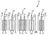
- FIG. 3is a cross-sectional view of an electrochemical cell including a double screen sandwich cathode electrode design according to the present invention.
- An electrochemical cell that possesses a double screen sandwich cathode electrode design according to the present inventionmust have sufficient energy density and discharge capacity in order to be a suitable power source for implantable medical devices.
- Such cellscomprise an anode of a metal selected from Groups IA, IIA and IIIB of the Periodic Table of the Elements.
- These anode active materialsinclude lithium, sodium, potassium, etc., and their alloys and intermetallic compounds including, for example, Li—Si, Li—Al, Li—B and Li—Si—B alloys and intermetallic compounds.
- the preferred anodecomprises lithium.
- An alternate anodecomprises a lithium alloy such as a lithium-aluminum alloy. The greater the amount of aluminum present by weight in the alloy, however, the lower the energy density of the cell.
- the form of the anodemay vary, but preferably the anode is a thin metal sheet or foil of the anode metal, pressed or rolled on a metallic anode current collector, i.e., preferably comprising titanium, titanium alloy or nickel, to form an anode component. Copper, tungsten and tantalum are also suitable materials for the anode current collector.
- the anode componenthas an extended tab or lead of the same material as the anode current collector, i.e., preferably nickel or titanium, integrally formed therewith such as by welding and contacted by a weld to a cell case of conductive metal in a case-negative electrical configuration.
- the anodemay be formed in some other geometry, such as a bobbin shape, cylinder or pellet to allow an alternate low surface cell design.
- the electrochemical cell of the present inventionfurther comprises a cathode of electrically conductive material which serves as the other electrode of the cell.
- the cathodeis preferably of solid materials and the electrochemical reaction at the cathode involves conversion of ions which migrate from the anode to the cathode into atomic or molecular forms.
- the solid cathodemay comprise a first active material of a metal element, a metal oxide, a mixed metal oxide and a metal sulfide, and combinations thereof and a second active material of a carbonaceous chemistry.
- the metal oxide, the mixed metal oxide and the metal sulfide of the first active materialhave a relatively lower energy density but a relatively higher rate capability than the second active material.
- the first active materialis formed by the chemical addition, reaction, or otherwise intimate contact of various metal oxides, metal sulfides and/or metal elements, preferably during thermal treatment, sol-gel formation, chemical vapor deposition or hydrothermal synthesis in mixed states.
- the active materials thereby producedcontain metals, oxides and sulfides of Groups, IB, IIB, IIIB, IVB, VB, VIB, VIIB and VIII, which includes the noble metals and/or other oxide and sulfide compounds.
- a preferred cathode active materialis a reaction product of at least silver and vanadium.
- One preferred mixed metal oxideis a transition metal oxide having the general formula SM x V 2 O y where SM is a metal selected from Groups IB to VIIB and VIII of the Periodic Table of Elements, wherein x is about 0.30 to 2.0 and y is about 4.5 to 6.0 in the general formula.
- Another preferred composite transition metal oxide cathode active materialis copper silver vanadium oxide (CSVO) having the general formula Cu x Ag y V 2 O z .
- This active materialincludes V 2 O z wherein z ⁇ 5 combined with Ag 2 O with silver in either the silver(II), silver(I) or silver(0) oxidation state and CuO with copper in either the copper(II), copper(I) or copper(0) oxidation state.
- the composite cathode active materialmay be described as a metal oxide-metal oxide-metal oxide, a metal-metal oxide-metal oxide, or a metal-metal-metal oxide and the range of material compositions found for Cu x Ag y V 2 O z is preferably about 0.01 ⁇ z ⁇ 6.5.
- Typical forms of CSVOare Cu 0.16 Ag 0.67 V 2 O z with z being about 5.5 and Cu 0.5 Ag 0.5 V 2 O z with z being about 5.75.
- the oxygen contentis designated by z since the exact stoichiometric proportion of oxygen in CSVO can vary depending on whether the cathode material is prepared in an oxidizing atmosphere such as air or oxygen, or in an inert atmosphere such as argon, nitrogen and helium.
- an oxidizing atmospheresuch as air or oxygen
- an inert atmospheresuch as argon, nitrogen and helium.
- the sandwich cathode design of the present inventionfurther includes a second active material of a relatively high energy density and a relatively low rate capability in comparison to the first cathode active material.
- the second active materialis preferably a carbonaceous compound prepared from carbon and fluorine, which includes graphitic and nongraphitic forms of carbon, such as coke, charcoal or activated carbon.
- Fluorinated carbonis represented by the formula (CF x ) n wherein x varies between about 0.1 to 1.9 and preferably between about 0.5 and 1.2, and (C 2 F) n wherein the n refers to the number of monomer units which can vary widely.
- the first cathode active materialis any material which has a relatively lower energy density but a relatively higher rate capability than the second cathode active material.
- V 2 O 5 , MnO 2 , LiCoO 2 , LiNiO 2 , LiMn 2 O 4 , TiS 2 , Cu 2 S, FeS, FeS 2 , copper oxide, copper vanadium oxide, and mixtures thereofare useful as the first active material, and in addition to fluorinated carbon, Ag 2 O, Ag 2 O 2 , CuF 2 , Ag 2 CrO 4 , MnO 2 and even SVO itself are useful as the second active material.
- the first and second cathode active materials prepared as described aboveare preferably mixed with a binder material such as a powdered fluoro-polymer, more preferably powdered polytetrafluoroethylene or powdered polyvinylidene flouride present at about 1 to about 5 weight percent of the cathode mixture.
- a binder materialsuch as a powdered fluoro-polymer, more preferably powdered polytetrafluoroethylene or powdered polyvinylidene flouride present at about 1 to about 5 weight percent of the cathode mixture.
- a conductive diluentis preferably added to the cathode mixture to improve conductivity.
- Suitable materials for this purposeinclude acetylene black, carbon black and/or graphite or a metallic powder such as powdered nickel, aluminum, titanium and stainless steel.
- the preferred cathode active mixturethus includes a powdered fluoro-polymer binder present at about 3 weight percent, a conductive
- Cathode components for incorporation into an electrochemical cell according to the present inventionmay be prepared by rolling, spreading or pressing the first and second cathode active materials onto a suitable current collector selected from the group consisting of stainless steel, titanium, tantalum, platinum, gold, aluminum, cobalt nickel alloys, nickel-containing alloys, highly alloyed ferritic stainless steel containing molybdenum and chromium, and nickel-, chromium- and molybdenum-containing alloys.
- the preferred current collector materialis titanium, and most preferably the titanium cathode current collector has a thin layer of graphite/carbon material, iridium, iridium oxide or platinum applied thereto.
- Cathodes prepared as described abovemay be in the form of one or more plates operatively associated with at least one or more plates of anode material, or in the form of a strip wound with a corresponding strip of anode material in a structure similar to a “jellyroll”.
- the sandwich cathodeis separated from the Group IA, IIA or IIIB anode by a suitable separator material.
- the separatoris of electrically insulative material, and the separator material also is chemically unreactive with the anode and cathode active materials and both chemically unreactive with and insoluble in the electrolyte.
- the separator materialhas a degree of porosity sufficient to allow flow there through of the electrolyte during the electrochemical reaction of the cell.
- Illustrative separator materialsinclude fabrics woven from fluoropolymeric fibers including polyvinylidine fluoride, polyethylenetetrafluoroethylene, and polyethylenechlorotrifluoroethylene used either alone or laminated with a fluoropolymeric microporous film, non-woven glass, polypropylene, polyethylene, glass fiber materials, ceramics, a polytetrafluoroethylene membrane commercially available under the designation ZITEX (Chemplast Inc.), a polypropylene membrane commercially available under the designation CELGARD (Celanese Plastic Company, Inc.) and a membrane commercially available under the designation DEXIGLAS (C.H. Dexter, Div., Dexter Corp.).
- fluoropolymeric fibersincluding polyvinylidine fluoride, polyethylenetetrafluoroethylene, and polyethylenechlorotrifluoroethylene used either alone or laminated with a fluoropolymeric microporous film, non-woven glass, polypropylene, polyethylene
- FIG. 3shows a detailed cross-sectional view of a double screen sandwich cathode electrode assembly 60 including an anode electrode 62 and a sandwich cathode electrode 64 segregated from each other by separator sheets 66 .
- the anode electrode 62comprises an anode active material 68 , such as lithium, contacted to at least one side of an anode current collector 70 .
- the sandwich cathode electrode 64is the same as the sandwich cathode electrode 34 shown in FIG. 2 and includes spaced apart cathode current collectors 72 and 74 having a first cathode active material 76 sandwiched between them.
- the cathode active material 76is of relatively high energy density but of a relatively low rate capability.
- a second cathode active material 78is contacted to the opposite sides of the current collectors 72 , 74 .
- the second cathode active material 78is of a relatively low energy density but of a relatively high rate capability.
- one exemplary sandwich cathode electrode designhas the following configuration:
- Another sandwich cathode electrode designhas the following configuration:
- the double screen sandwich cathode electrode assembly 60further includes at least one half double screen sandwich cathode 80 .
- the cathode 80comprises a cathode current collector 82 having a third cathode active material 76 contacted to one side thereof, and a fourth cathode active material 78 contacted to the other side of the current collector.
- the third cathode active material 76is of a relatively high energy density but of a relatively low rate capability while the fourth cathode active material 78 is of a relatively low energy density but of a relatively high rate capability.
- the fourth cathode active material 78faces the anode active material 68 .
- the first and third cathode active materialsare the same and the second and fourth cathode active materials are the same.
- the high capacity material having the low rate capabilityis preferably positioned between two layers of high rate cathode material (either high or low capacities).
- the exemplary CF x materialnever directly faces the lithium anode.
- the low rate cathode materialmust be short circuited with the high rate material, either by direct contact as demonstrated above in the second illustrated configuration, or by parallel connection through the current collectors as in the first illustrated configuration above.
- the sandwich cathode electrode assembly illustrated in the previously described FIG. 2has the following configuration:
- a half double screen sandwich cathodeis defined as SVO/screen/CF x .
- the half double screen sandwich cathodecan be thought of as having been provided by cutting a full sandwich cathode electrode in half down the middle of the CF x layer.
- the detailed cross section of a half double screen sandwich cathodeis shown in the previously described FIG. 3 .
- the number of layers for each componentsis calculated as:
- the double screen sandwich cathode electrode assemblyrepresents an improvement in cell packaging efficiency over that known before.
- the volumetric energy density of cells having an electrode assembly according to FIG. 3 of the present inventionis higher than that of cells having a sandwich cathode electrode assembly, as shown in FIG. 2 .
- the electrochemical cell of the present inventionfurther includes a nonaqueous, ionically conductive electrolyte which serves as a medium for migration of ions between the anode and the cathode electrodes during electrochemical reactions of the cell.
- the electrochemical reaction at the electrodesinvolves conversion of ions in atomic or molecular forms which migrate from the anode to the cathode.
- nonaqueous electrolytes suitable for the present inventionare substantially inert to the anode and cathode materials, and they exhibit those physical properties necessary for ionic transport, namely, low viscosity, low surface tension and wettability.
- a suitable electrolytehas an inorganic, tonically conductive salt dissolved in a nonaqueous solvent, and more preferably, the electrolyte includes an ionizable alkali metal salt dissolved in a mixture of aprotic organic solvents comprising a low viscosity solvent and a high permittivity solvent.
- the inorganic, tonically conductive saltserves as the vehicle for migration of the anode ions to intercalate or react with the cathode active materials.
- the ion forming alkali metal saltis similar to the alkali metal comprising the anode.
- the alkali metal salt of the electrolyteis a lithium based salt.
- Known lithium salts that are useful as a vehicle for transport of alkali metal ions from the anode to the cathodeinclude LiPF 6 , LiBF 4 , LiAsF 6 , LiSbF 6 , LiClO 4 , LiO 2 , LiAlCl 4 , LiGaCl 4 , LiC(SO 2 CF 3 ) 3 , LiN (SO 2 CF 3 ) 2 , LiSCN, LiO 3 SCF 3 , LiC 6 F 5 SO 3 , LiO 2 CCF 3 , LiSO 6 F, LiB(C 6 H 5 ) 4 , LiCF 3 SO 3 , and mixtures thereof.
- Low viscosity solvents useful with the present inventioninclude esters, linear and cyclic ethers and dialkyl carbonates such as tetrahydrofuran (THF), methyl acetate (MA), diglyme, trigylme, tetragylme, dimethyl carbonate (DMC), 1,2-dimethoxyethane (DME), 1,2-diethoxyethane (DEE), 1-ethoxy,2-methoxyethane (EME), ethyl methyl carbonate, methyl propyl carbonate, ethyl propyl carbonate, diethyl carbonate, dipropyl carbonate, and mixtures thereof, and high permittivity solvents including cyclic carbonates, cyclic esters, cyclic amides and a sulfoxide such as propylene carbonate (PC), ethylene carbonate (EC), butylene carbonate, acetonitrile, dimethyl sulfoxide, dimethyl formamide, dimethyl acetamide, ⁇
- the preferred anode active materialis lithium metal and the preferred electrolyte is 0.8M to 1.5M LiAsF 6 or LiPF 6 dissolved in a 50:50 mixture, by volume, of propylene carbonate as the preferred high permittivity solvent and 1,2-dimethoxyethane as the preferred low viscosity solvent.
Landscapes
- Chemical & Material Sciences (AREA)
- Chemical Kinetics & Catalysis (AREA)
- Electrochemistry (AREA)
- General Chemical & Material Sciences (AREA)
- Engineering & Computer Science (AREA)
- Manufacturing & Machinery (AREA)
- Inorganic Chemistry (AREA)
- Composite Materials (AREA)
- Crystallography & Structural Chemistry (AREA)
- Materials Engineering (AREA)
- Physics & Mathematics (AREA)
- Condensed Matter Physics & Semiconductors (AREA)
- General Physics & Mathematics (AREA)
- Secondary Cells (AREA)
- Battery Electrode And Active Subsutance (AREA)
- Primary Cells (AREA)
- Cell Electrode Carriers And Collectors (AREA)
Abstract
Description
Claims (30)
Priority Applications (1)
| Application Number | Priority Date | Filing Date | Title |
|---|---|---|---|
| US09/845,875US6645670B2 (en) | 2000-05-16 | 2001-04-30 | Efficient cell stack for cells with double current collectors sandwich cathodes |
Applications Claiming Priority (2)
| Application Number | Priority Date | Filing Date | Title |
|---|---|---|---|
| US20447700P | 2000-05-16 | 2000-05-16 | |
| US09/845,875US6645670B2 (en) | 2000-05-16 | 2001-04-30 | Efficient cell stack for cells with double current collectors sandwich cathodes |
Publications (2)
| Publication Number | Publication Date |
|---|---|
| US20010049032A1 US20010049032A1 (en) | 2001-12-06 |
| US6645670B2true US6645670B2 (en) | 2003-11-11 |
Family
ID=22758052
Family Applications (1)
| Application Number | Title | Priority Date | Filing Date |
|---|---|---|---|
| US09/845,875Expired - LifetimeUS6645670B2 (en) | 2000-05-16 | 2001-04-30 | Efficient cell stack for cells with double current collectors sandwich cathodes |
Country Status (4)
| Country | Link |
|---|---|
| US (1) | US6645670B2 (en) |
| EP (1) | EP1156544A3 (en) |
| JP (1) | JP2002015725A (en) |
| CA (1) | CA2346601C (en) |
Cited By (29)
| Publication number | Priority date | Publication date | Assignee | Title |
|---|---|---|---|---|
| US20030134188A1 (en)* | 2002-01-17 | 2003-07-17 | Roy Mark J. | Sandwich electrode design having relatively thin current collectors |
| US7108942B1 (en) | 2003-03-27 | 2006-09-19 | Wilson Greatbatch Technologies, Inc. | Efficient electrode assembly design for cells with alkali metal anodes |
| US20070292600A1 (en)* | 2006-06-19 | 2007-12-20 | Morgan Adam J | Pressed powder pellet battery electrode system |
| US20080026293A1 (en)* | 2006-07-26 | 2008-01-31 | Eveready Battery Company, Inc. | Lithium-iron disulfide cylindrical cell with modified positive electrode |
| US20080026288A1 (en)* | 2006-07-26 | 2008-01-31 | Eveready Battery Company, Inc. | Electrochemical cell with positive container |
| US7531274B1 (en) | 2002-01-17 | 2009-05-12 | Greatbatch Ltd. | Sandwich electrode design having relatively thin current collectors |
| WO2010009158A1 (en)* | 2008-07-14 | 2010-01-21 | A123 Systems, Inc. | Prismatic cell with outer electrode layers coated on a single side |
| US7682745B2 (en) | 2004-10-29 | 2010-03-23 | Medtronic, Inc. | Medical device having lithium-ion battery |
| US7740985B2 (en) | 2004-10-29 | 2010-06-22 | Medtronic, Inc. | Lithium-ion battery |
| US7794869B2 (en) | 2004-10-29 | 2010-09-14 | Medtronic, Inc. | Lithium-ion battery |
| US7807299B2 (en) | 2004-10-29 | 2010-10-05 | Medtronic, Inc. | Lithium-ion battery |
| US20100273036A1 (en)* | 2006-10-17 | 2010-10-28 | Eveready Battery Company, Inc. | Lithium-Iron Disulfide Cell Design with Core Reinforcement |
| US20100279155A1 (en)* | 2009-04-30 | 2010-11-04 | Medtronic, Inc. | Lithium-ion battery with electrolyte additive |
| US7858236B2 (en) | 2004-10-29 | 2010-12-28 | Medtronic, Inc. | Lithium-ion battery |
| US7883790B2 (en) | 2004-10-29 | 2011-02-08 | Medtronic, Inc. | Method of preventing over-discharge of battery |
| US7927742B2 (en) | 2004-10-29 | 2011-04-19 | Medtronic, Inc. | Negative-limited lithium-ion battery |
| US20110091776A1 (en)* | 2005-09-15 | 2011-04-21 | Greatbatch Ltd. | Sandwich Cathode Electrochemical Cell With Wound Electrode Assembly |
| US20110104542A1 (en)* | 2009-10-30 | 2011-05-05 | Greatbatch Ltd. | Screen-less anode design concepts for low cost lithium electrochemical cells for use in implantable medical device applications |
| US8105714B2 (en) | 2004-10-29 | 2012-01-31 | Medtronic, Inc. | Lithium-ion battery |
| US8241788B1 (en)* | 2004-12-13 | 2012-08-14 | Greatbatch Ltd. | Method for making flat and high-density cathode for use in electrochemical cells |
| US8785046B2 (en) | 2004-10-29 | 2014-07-22 | Medtronic, Inc. | Lithium-ion battery |
| US8980453B2 (en) | 2008-04-30 | 2015-03-17 | Medtronic, Inc. | Formation process for lithium-ion batteries |
| US9065145B2 (en) | 2004-10-29 | 2015-06-23 | Medtronic, Inc. | Lithium-ion battery |
| US9077022B2 (en) | 2004-10-29 | 2015-07-07 | Medtronic, Inc. | Lithium-ion battery |
| US9142840B2 (en) | 2011-10-21 | 2015-09-22 | Blackberry Limited | Method of reducing tabbing volume required for external connections |
| US9287580B2 (en) | 2011-07-27 | 2016-03-15 | Medtronic, Inc. | Battery with auxiliary electrode |
| US9587321B2 (en) | 2011-12-09 | 2017-03-07 | Medtronic Inc. | Auxiliary electrode for lithium-ion battery |
| US10263240B2 (en) | 2015-10-10 | 2019-04-16 | Greatbatch Ltd. | Sandwich cathode lithium battery with high energy density |
| US10446828B2 (en) | 2011-10-21 | 2019-10-15 | Blackberry Limited | Recessed tab for higher energy density and thinner batteries |
Families Citing this family (28)
| Publication number | Priority date | Publication date | Assignee | Title |
|---|---|---|---|---|
| JP3479618B2 (en)* | 1999-10-14 | 2003-12-15 | Necトーキン株式会社 | Electrode molded body, method for producing the same, and secondary battery using the same |
| GB0021466D0 (en)* | 2000-09-01 | 2000-10-18 | Univ Leeds Innovations Ltd | Extruded battery components |
| US6790561B2 (en)* | 2001-03-15 | 2004-09-14 | Wilson Greatbatch Ltd. | Process for fabricating continuously coated electrodes on a porous current collector and cell designs incorporating said electrodes |
| US6926991B2 (en)* | 2001-12-26 | 2005-08-09 | Wilson Greatbatch Technologies, Inc. | SVO/CFx parallel cell design within the same casing |
| US20030138697A1 (en)* | 2002-01-24 | 2003-07-24 | Randolph Leising | Cathode active material coated with a metal oxide for incorporation into a lithium electrochemical cell |
| US20100185264A1 (en)* | 2002-01-24 | 2010-07-22 | Greatbatch Ltd. | Method For Coating A Cathode Active Material With A Metal Oxide For Incorporation Into A Lithium Electrochemical Cell |
| AU2003211452A1 (en)* | 2002-02-25 | 2003-10-08 | Bridgestone Corporation | Positive electrode for nonaqueous electrolyte battery, process for producing the same and nonaqueous electrolyte battery |
| US7482097B2 (en)* | 2002-04-03 | 2009-01-27 | Valence Technology, Inc. | Alkali-transition metal phosphates having a +3 valence non-transition element and related electrode active materials |
| US7422823B2 (en)* | 2002-04-03 | 2008-09-09 | Valence Technology, Inc. | Alkali-iron-cobalt phosphates and related electrode active materials |
| US20030190527A1 (en)* | 2002-04-03 | 2003-10-09 | James Pugh | Batteries comprising alkali-transition metal phosphates and preferred electrolytes |
| US20040185346A1 (en)* | 2003-03-19 | 2004-09-23 | Takeuchi Esther S. | Electrode having metal vanadium oxide nanoparticles for alkali metal-containing electrochemical cells |
| US20050048366A1 (en) | 2003-08-27 | 2005-03-03 | Bowden William L. | Cathode material and method of manufacturing |
| US8883354B2 (en) | 2006-02-15 | 2014-11-11 | Optodot Corporation | Separators for electrochemical cells |
| KR100912788B1 (en) | 2006-09-11 | 2009-08-18 | 주식회사 엘지화학 | Electrode assembly with excellent pulse discharge characteristics |
| KR20180081752A (en) | 2009-05-26 | 2018-07-17 | 옵토도트 코포레이션 | Batteries utilizing electrode coatings directly on nanoporous separators |
| CN103283060B (en) | 2010-07-19 | 2017-02-15 | 奥普图多特公司 | Separators for electrochemical cells |
| US10879513B2 (en) | 2013-04-29 | 2020-12-29 | Optodot Corporation | Nanoporous composite separators with increased thermal conductivity |
| US12040506B2 (en) | 2015-04-15 | 2024-07-16 | Lg Energy Solution, Ltd. | Nanoporous separators for batteries and related manufacturing methods |
| US10381623B2 (en) | 2015-07-09 | 2019-08-13 | Optodot Corporation | Nanoporous separators for batteries and related manufacturing methods |
| JP6738522B2 (en)* | 2015-11-13 | 2020-08-12 | トヨタ自動車株式会社 | Electrode structure for secondary battery |
| FR3070544B1 (en)* | 2017-08-30 | 2023-01-27 | Centre Nat Rech Scient | CURRENT COLLECTION MULTIPLE ARRAY ELECTRODE |
| CN112447937B (en)* | 2019-09-04 | 2024-07-09 | 通用汽车环球科技运作有限责任公司 | Electrochemical cell with high aspect ratio electrode |
| GB2590399B (en)* | 2019-12-16 | 2024-07-17 | Dyson Technology Ltd | Electrode current collector Architectures |
| KR20220049947A (en) | 2020-10-15 | 2022-04-22 | 현대자동차주식회사 | Iron loss reduction control apparatus and method for motor permanent magnet overtemperature protection |
| CN112271306B (en)* | 2020-10-30 | 2022-03-25 | 上海空间电源研究所 | Low-temperature electrolyte for lithium-cobalt disulfide primary battery and lithium-cobalt disulfide primary battery |
| CN117256062A (en) | 2021-04-29 | 2023-12-19 | 24M技术公司 | Electrochemical cell with multiple separator membranes and method of producing the same |
| TW202443944A (en) | 2022-12-16 | 2024-11-01 | 美商24M科技公司 | Systems and methods for minimizing and preventing dendrite formation in electrochemical cells |
| US12431545B1 (en) | 2024-03-26 | 2025-09-30 | 24M Technologies, Inc. | Systems and methods for minimizing and preventing dendrite formation in electrochemical cells |
Citations (24)
| Publication number | Priority date | Publication date | Assignee | Title |
|---|---|---|---|---|
| US2594712A (en) | 1949-02-22 | 1952-04-29 | Yardney International Corp | Silver and zinc accumulator having an insoluble negative electrode |
| US2661388A (en) | 1951-08-29 | 1953-12-01 | Fed Telecomm Lab Inc | Primary cells |
| US2662928A (en) | 1950-02-25 | 1953-12-15 | Joseph B Brennan | Storage battery electrode |
| US2669594A (en) | 1951-03-30 | 1954-02-16 | Yardney International Corp | Electrical accumulator |
| US3736184A (en) | 1972-03-29 | 1973-05-29 | Mallory & Co Inc P R | Metal phosphate and metal arsenate organic electrolyte cells |
| US4091185A (en) | 1976-07-27 | 1978-05-23 | Yardney Electric Corporation | Titanium/silver-containing cellulosic separator for electrochemical cells |
| US4098967A (en) | 1973-05-23 | 1978-07-04 | Gould Inc. | Electrochemical system using conductive plastic |
| US4211833A (en) | 1978-12-08 | 1980-07-08 | Exxon Research & Engineering Co. | Bipolar battery |
| US4960655A (en) | 1989-01-27 | 1990-10-02 | Hope Henry F | Lightweight batteries |
| US5180642A (en)* | 1992-02-24 | 1993-01-19 | Medtronic, Inc. | Electrochemical cells with end-of-service indicator |
| EP0532313A1 (en) | 1991-09-10 | 1993-03-17 | Wilson Greatbatch Ltd. | Twin plate cathode assembly for multiplate electrochemical cells |
| US5322746A (en) | 1992-10-02 | 1994-06-21 | Her Majesty The Queen In Right Of The Province Of British Columbia As Represented By The Minister Of Finance & Corporate Relations | Electrode composition and design for high energy density cells |
| US5368952A (en) | 1991-06-12 | 1994-11-29 | Stork Screens B.V. | Metal suspension half-cell for an accumulator, method for operating such a half-cell and metal suspension accumulator comprising such a half-cell |
| US5368961A (en) | 1989-06-14 | 1994-11-29 | Bolder Battery, Inc. | Thin plate electrochemical cell |
| US5478668A (en) | 1993-11-30 | 1995-12-26 | Bell Communications Research Inc. | Rechargeable lithium battery construction |
| EP0689256A1 (en) | 1994-06-21 | 1995-12-27 | Wilson Greatbatch Ltd. | Cathode material for nonaqueous electrochemical cells |
| US5658694A (en) | 1996-09-27 | 1997-08-19 | Energy Research Corporation | Simplified zinc negative electrode with multiple electrode assemblies |
| US5667916A (en)* | 1996-05-10 | 1997-09-16 | Wilson Greatbatch Ltd. | Mixed cathode formulation for achieving end-of-life indication |
| US5744258A (en) | 1996-12-23 | 1998-04-28 | Motorola,Inc. | High power, high energy, hybrid electrode and electrical energy storage device made therefrom |
| US5811206A (en)* | 1997-10-31 | 1998-09-22 | Medtronic, Inc. | Feedthrough pin insulator, assembly and method for electrochemical cell |
| US5894656A (en) | 1997-04-11 | 1999-04-20 | Valence Technology, Inc. | Methods of fabricating electrochemical cells |
| US5955217A (en) | 1996-06-19 | 1999-09-21 | U.S. Philips Corporation | Thin card including a flat battery and contact means |
| US5993999A (en) | 1998-05-15 | 1999-11-30 | Aer Energy Resources, Inc. | Multi-layer current collector |
| US6051333A (en) | 1995-11-08 | 2000-04-18 | Hitachi Maxell, Ltd. | Cell comprising spirally wound electrodes |
- 2001
- 2001-04-30USUS09/845,875patent/US6645670B2/ennot_activeExpired - Lifetime
- 2001-05-08CACA002346601Apatent/CA2346601C/ennot_activeExpired - Fee Related
- 2001-05-16JPJP2001145724Apatent/JP2002015725A/enactivePending
- 2001-05-16EPEP01304355Apatent/EP1156544A3/ennot_activeWithdrawn
Patent Citations (24)
| Publication number | Priority date | Publication date | Assignee | Title |
|---|---|---|---|---|
| US2594712A (en) | 1949-02-22 | 1952-04-29 | Yardney International Corp | Silver and zinc accumulator having an insoluble negative electrode |
| US2662928A (en) | 1950-02-25 | 1953-12-15 | Joseph B Brennan | Storage battery electrode |
| US2669594A (en) | 1951-03-30 | 1954-02-16 | Yardney International Corp | Electrical accumulator |
| US2661388A (en) | 1951-08-29 | 1953-12-01 | Fed Telecomm Lab Inc | Primary cells |
| US3736184A (en) | 1972-03-29 | 1973-05-29 | Mallory & Co Inc P R | Metal phosphate and metal arsenate organic electrolyte cells |
| US4098967A (en) | 1973-05-23 | 1978-07-04 | Gould Inc. | Electrochemical system using conductive plastic |
| US4091185A (en) | 1976-07-27 | 1978-05-23 | Yardney Electric Corporation | Titanium/silver-containing cellulosic separator for electrochemical cells |
| US4211833A (en) | 1978-12-08 | 1980-07-08 | Exxon Research & Engineering Co. | Bipolar battery |
| US4960655A (en) | 1989-01-27 | 1990-10-02 | Hope Henry F | Lightweight batteries |
| US5368961A (en) | 1989-06-14 | 1994-11-29 | Bolder Battery, Inc. | Thin plate electrochemical cell |
| US5368952A (en) | 1991-06-12 | 1994-11-29 | Stork Screens B.V. | Metal suspension half-cell for an accumulator, method for operating such a half-cell and metal suspension accumulator comprising such a half-cell |
| EP0532313A1 (en) | 1991-09-10 | 1993-03-17 | Wilson Greatbatch Ltd. | Twin plate cathode assembly for multiplate electrochemical cells |
| US5180642A (en)* | 1992-02-24 | 1993-01-19 | Medtronic, Inc. | Electrochemical cells with end-of-service indicator |
| US5322746A (en) | 1992-10-02 | 1994-06-21 | Her Majesty The Queen In Right Of The Province Of British Columbia As Represented By The Minister Of Finance & Corporate Relations | Electrode composition and design for high energy density cells |
| US5478668A (en) | 1993-11-30 | 1995-12-26 | Bell Communications Research Inc. | Rechargeable lithium battery construction |
| EP0689256A1 (en) | 1994-06-21 | 1995-12-27 | Wilson Greatbatch Ltd. | Cathode material for nonaqueous electrochemical cells |
| US6051333A (en) | 1995-11-08 | 2000-04-18 | Hitachi Maxell, Ltd. | Cell comprising spirally wound electrodes |
| US5667916A (en)* | 1996-05-10 | 1997-09-16 | Wilson Greatbatch Ltd. | Mixed cathode formulation for achieving end-of-life indication |
| US5955217A (en) | 1996-06-19 | 1999-09-21 | U.S. Philips Corporation | Thin card including a flat battery and contact means |
| US5658694A (en) | 1996-09-27 | 1997-08-19 | Energy Research Corporation | Simplified zinc negative electrode with multiple electrode assemblies |
| US5744258A (en) | 1996-12-23 | 1998-04-28 | Motorola,Inc. | High power, high energy, hybrid electrode and electrical energy storage device made therefrom |
| US5894656A (en) | 1997-04-11 | 1999-04-20 | Valence Technology, Inc. | Methods of fabricating electrochemical cells |
| US5811206A (en)* | 1997-10-31 | 1998-09-22 | Medtronic, Inc. | Feedthrough pin insulator, assembly and method for electrochemical cell |
| US5993999A (en) | 1998-05-15 | 1999-11-30 | Aer Energy Resources, Inc. | Multi-layer current collector |
Cited By (43)
| Publication number | Priority date | Publication date | Assignee | Title |
|---|---|---|---|---|
| US7531274B1 (en) | 2002-01-17 | 2009-05-12 | Greatbatch Ltd. | Sandwich electrode design having relatively thin current collectors |
| US20030134188A1 (en)* | 2002-01-17 | 2003-07-17 | Roy Mark J. | Sandwich electrode design having relatively thin current collectors |
| US7108942B1 (en) | 2003-03-27 | 2006-09-19 | Wilson Greatbatch Technologies, Inc. | Efficient electrode assembly design for cells with alkali metal anodes |
| US7803481B2 (en)* | 2004-10-29 | 2010-09-28 | Medtronic, Inc, | Lithium-ion battery |
| US7811705B2 (en) | 2004-10-29 | 2010-10-12 | Medtronic, Inc. | Lithium-ion battery |
| US9077022B2 (en) | 2004-10-29 | 2015-07-07 | Medtronic, Inc. | Lithium-ion battery |
| US8785046B2 (en) | 2004-10-29 | 2014-07-22 | Medtronic, Inc. | Lithium-ion battery |
| US7682745B2 (en) | 2004-10-29 | 2010-03-23 | Medtronic, Inc. | Medical device having lithium-ion battery |
| US7740985B2 (en) | 2004-10-29 | 2010-06-22 | Medtronic, Inc. | Lithium-ion battery |
| US7794869B2 (en) | 2004-10-29 | 2010-09-14 | Medtronic, Inc. | Lithium-ion battery |
| US8105714B2 (en) | 2004-10-29 | 2012-01-31 | Medtronic, Inc. | Lithium-ion battery |
| US7807299B2 (en) | 2004-10-29 | 2010-10-05 | Medtronic, Inc. | Lithium-ion battery |
| US9065145B2 (en) | 2004-10-29 | 2015-06-23 | Medtronic, Inc. | Lithium-ion battery |
| US8383269B2 (en) | 2004-10-29 | 2013-02-26 | Medtronic, Inc. | Negative-limited lithium-ion battery |
| US8178242B2 (en) | 2004-10-29 | 2012-05-15 | Medtronic, Inc. | Lithium-ion battery |
| US7858236B2 (en) | 2004-10-29 | 2010-12-28 | Medtronic, Inc. | Lithium-ion battery |
| US7875389B2 (en) | 2004-10-29 | 2011-01-25 | Medtronic, Inc. | Lithium-ion battery |
| US7879495B2 (en) | 2004-10-29 | 2011-02-01 | Medtronic, Inc. | Medical device having lithium-ion battery |
| US7883790B2 (en) | 2004-10-29 | 2011-02-08 | Medtronic, Inc. | Method of preventing over-discharge of battery |
| US7927742B2 (en) | 2004-10-29 | 2011-04-19 | Medtronic, Inc. | Negative-limited lithium-ion battery |
| US7931987B2 (en) | 2004-10-29 | 2011-04-26 | Medtronic, Inc. | Lithium-ion battery |
| US9231256B2 (en) | 2004-12-13 | 2016-01-05 | Greatbatch Ltd. | Flat and high-density cathodes for use in electrochemical cells |
| US8241788B1 (en)* | 2004-12-13 | 2012-08-14 | Greatbatch Ltd. | Method for making flat and high-density cathode for use in electrochemical cells |
| US20110091776A1 (en)* | 2005-09-15 | 2011-04-21 | Greatbatch Ltd. | Sandwich Cathode Electrochemical Cell With Wound Electrode Assembly |
| US8153293B2 (en)* | 2005-09-15 | 2012-04-10 | Greatbatch Ltd. | Sandwich cathode electrochemical cell with wound electrode assembly |
| US20070292600A1 (en)* | 2006-06-19 | 2007-12-20 | Morgan Adam J | Pressed powder pellet battery electrode system |
| US20080026288A1 (en)* | 2006-07-26 | 2008-01-31 | Eveready Battery Company, Inc. | Electrochemical cell with positive container |
| US20080026293A1 (en)* | 2006-07-26 | 2008-01-31 | Eveready Battery Company, Inc. | Lithium-iron disulfide cylindrical cell with modified positive electrode |
| EP2365564A1 (en) | 2006-07-26 | 2011-09-14 | Eveready Battery Company, Inc. | Electrochemical cell with positive container |
| US20100273036A1 (en)* | 2006-10-17 | 2010-10-28 | Eveready Battery Company, Inc. | Lithium-Iron Disulfide Cell Design with Core Reinforcement |
| US9899710B2 (en) | 2008-04-30 | 2018-02-20 | Medtronic, Inc. | Charging process for lithium-ion batteries |
| US8980453B2 (en) | 2008-04-30 | 2015-03-17 | Medtronic, Inc. | Formation process for lithium-ion batteries |
| US10615463B2 (en) | 2008-04-30 | 2020-04-07 | Medtronic, Inc. | Formation process for lithium-ion batteries with improved tolerace to overdischarge conditions |
| WO2010009158A1 (en)* | 2008-07-14 | 2010-01-21 | A123 Systems, Inc. | Prismatic cell with outer electrode layers coated on a single side |
| US20100279155A1 (en)* | 2009-04-30 | 2010-11-04 | Medtronic, Inc. | Lithium-ion battery with electrolyte additive |
| US20110104542A1 (en)* | 2009-10-30 | 2011-05-05 | Greatbatch Ltd. | Screen-less anode design concepts for low cost lithium electrochemical cells for use in implantable medical device applications |
| US8871379B2 (en) | 2009-10-30 | 2014-10-28 | Greatbatch Ltd. | Screen-less anode design concepts for low cost lithium electrochemical cells for use in implantable medical device applications |
| US9287580B2 (en) | 2011-07-27 | 2016-03-15 | Medtronic, Inc. | Battery with auxiliary electrode |
| US10446828B2 (en) | 2011-10-21 | 2019-10-15 | Blackberry Limited | Recessed tab for higher energy density and thinner batteries |
| US9142840B2 (en) | 2011-10-21 | 2015-09-22 | Blackberry Limited | Method of reducing tabbing volume required for external connections |
| US9587321B2 (en) | 2011-12-09 | 2017-03-07 | Medtronic Inc. | Auxiliary electrode for lithium-ion battery |
| US10263240B2 (en) | 2015-10-10 | 2019-04-16 | Greatbatch Ltd. | Sandwich cathode lithium battery with high energy density |
| US11075377B2 (en) | 2015-10-10 | 2021-07-27 | Greatbatch Ltd. | Sandwich cathode lithium battery with high energy density |
Also Published As
| Publication number | Publication date |
|---|---|
| CA2346601A1 (en) | 2001-11-16 |
| EP1156544A2 (en) | 2001-11-21 |
| US20010049032A1 (en) | 2001-12-06 |
| CA2346601C (en) | 2005-07-26 |
| JP2002015725A (en) | 2002-01-18 |
| EP1156544A3 (en) | 2003-05-07 |
Similar Documents
| Publication | Publication Date | Title |
|---|---|---|
| US6645670B2 (en) | Efficient cell stack for cells with double current collectors sandwich cathodes | |
| US7018743B2 (en) | Dual chemistry electrode design | |
| US8153293B2 (en) | Sandwich cathode electrochemical cell with wound electrode assembly | |
| US6551747B1 (en) | Sandwich cathode design for alkali metal electrochemical cell with high discharge rate capability | |
| US6727022B2 (en) | Powder process for double current collector screen cathode preparation | |
| US6692871B2 (en) | Double current collector cathode design for alkali metal electrochemical cells having short circuit safety characteristics | |
| US6673493B2 (en) | Double current collector cathode design using the same active material in varying formulations for alkali metal or ion electrochemical cells | |
| US6743547B2 (en) | Pellet process for double current collector screen cathode preparation | |
| US20020012844A1 (en) | Control of cell swelling by the proper choice of carbon monofluoride (CFx) cathode materials in high rate defibrillator cells | |
| US6926991B2 (en) | SVO/CFx parallel cell design within the same casing | |
| US20030134188A1 (en) | Sandwich electrode design having relatively thin current collectors | |
| US7108942B1 (en) | Efficient electrode assembly design for cells with alkali metal anodes | |
| JP2002198061A (en) | Alkaline metal electrochemical cell with short-circuit safety characteristic using double-collector cathode structure | |
| US8871379B2 (en) | Screen-less anode design concepts for low cost lithium electrochemical cells for use in implantable medical device applications | |
| US8192867B2 (en) | Hybrid cathode design for an electrochemical cell | |
| US6673487B2 (en) | Double current collector cathode design using the same active material in varying thicknesses for alkali metal or ION electrochemical cells | |
| EP1914823B1 (en) | Hybrid cathode design for an electrochemical cell | |
| US20100196765A1 (en) | Reducing DC Resistance In Electrochemical Cells By Increasing Cathode Basis Weight | |
| US9231256B2 (en) | Flat and high-density cathodes for use in electrochemical cells |
Legal Events
| Date | Code | Title | Description |
|---|---|---|---|
| AS | Assignment | Owner name:WILSON GREATBATCH LTD., NEW YORK Free format text:ASSIGNMENT OF ASSIGNORS INTEREST;ASSIGNOR:GAN, HONG;REEL/FRAME:011777/0649 Effective date:20010425 | |
| STCF | Information on status: patent grant | Free format text:PATENTED CASE | |
| FPAY | Fee payment | Year of fee payment:4 | |
| AS | Assignment | Owner name:GREATBATCH, LTD. (NEW YORK CORPORATION), NEW YORK Free format text:CHANGE OF NAME;ASSIGNOR:WILSON GREATBATCH,TD.;REEL/FRAME:019520/0743 Effective date:20050524 | |
| AS | Assignment | Owner name:MANUFACTURERS AND TRADERS TRUST COMPANY,NEW YORK Free format text:SECURITY INTEREST;ASSIGNOR:GREATBATCH LTD.;REEL/FRAME:020571/0205 Effective date:20070522 Owner name:MANUFACTURERS AND TRADERS TRUST COMPANY, NEW YORK Free format text:SECURITY INTEREST;ASSIGNOR:GREATBATCH LTD.;REEL/FRAME:020571/0205 Effective date:20070522 | |
| FEPP | Fee payment procedure | Free format text:PAYOR NUMBER ASSIGNED (ORIGINAL EVENT CODE: ASPN); ENTITY STATUS OF PATENT OWNER: LARGE ENTITY | |
| FPAY | Fee payment | Year of fee payment:8 | |
| FPAY | Fee payment | Year of fee payment:12 | |
| AS | Assignment | Owner name:MANUFACTURERS AND TRADERS TRUST COMPANY, NEW YORK Free format text:SECURITY INTEREST;ASSIGNORS:GREATBATCH, INC.;GREATBATCH LTD.;ELECTROCHEM SOLUTIONS, INC.;AND OTHERS;REEL/FRAME:036980/0482 Effective date:20151027 | |
| AS | Assignment | Owner name:WELLS FARGO BANK, NATIONAL ASSOCIATION, AS ADMINISTRATIVE AGENT, VIRGINIA Free format text:SECURITY INTEREST;ASSIGNORS:GREATBATCH LTD.;ELECTROCHEM SOLUTIONS, INC.;LAKE REGION MEDICAL, INC.;AND OTHERS;REEL/FRAME:057468/0056 Effective date:20210902 | |
| AS | Assignment | Owner name:MICRO POWER ELECTRONICS, INC., NEW YORK Free format text:RELEASE BY SECURED PARTY;ASSIGNOR:MANUFACTURERS AND TRADERS TRUST COMPANY (AS ADMINISTRATIVE AGENT);REEL/FRAME:060938/0069 Effective date:20210903 Owner name:PRECIMED INC., NEW YORK Free format text:RELEASE BY SECURED PARTY;ASSIGNOR:MANUFACTURERS AND TRADERS TRUST COMPANY (AS ADMINISTRATIVE AGENT);REEL/FRAME:060938/0069 Effective date:20210903 Owner name:GREATBATCH-GLOBE TOOL, INC., NEW YORK Free format text:RELEASE BY SECURED PARTY;ASSIGNOR:MANUFACTURERS AND TRADERS TRUST COMPANY (AS ADMINISTRATIVE AGENT);REEL/FRAME:060938/0069 Effective date:20210903 Owner name:NEURONEXUS TECHNOLOGIES, INC., NEW YORK Free format text:RELEASE BY SECURED PARTY;ASSIGNOR:MANUFACTURERS AND TRADERS TRUST COMPANY (AS ADMINISTRATIVE AGENT);REEL/FRAME:060938/0069 Effective date:20210903 Owner name:ELECTROCHEM SOLUTIONS, INC., NEW YORK Free format text:RELEASE BY SECURED PARTY;ASSIGNOR:MANUFACTURERS AND TRADERS TRUST COMPANY (AS ADMINISTRATIVE AGENT);REEL/FRAME:060938/0069 Effective date:20210903 Owner name:GREATBATCH LTD., NEW YORK Free format text:RELEASE BY SECURED PARTY;ASSIGNOR:MANUFACTURERS AND TRADERS TRUST COMPANY (AS ADMINISTRATIVE AGENT);REEL/FRAME:060938/0069 Effective date:20210903 Owner name:GREATBATCH, INC., NEW YORK Free format text:RELEASE BY SECURED PARTY;ASSIGNOR:MANUFACTURERS AND TRADERS TRUST COMPANY (AS ADMINISTRATIVE AGENT);REEL/FRAME:060938/0069 Effective date:20210903 Owner name:GREATBATCH LTD., NEW YORK Free format text:RELEASE BY SECURED PARTY;ASSIGNOR:MANUFACTURERS AND TRADERS TRUST COMPANY (AS ADMINISTRATIVE AGENT);REEL/FRAME:058574/0437 Effective date:20210903 | |
| AS | Assignment | Owner name:MICRO POWER ELECTRONICS, INC., NEW YORK Free format text:RELEASE BY SECURED PARTY;ASSIGNOR:MANUFACTURERS AND TRADERS TRUST COMPANY (AS ADMINISTRATIVE AGENT);REEL/FRAME:061659/0858 Effective date:20210903 Owner name:PRECIMED INC., NEW YORK Free format text:RELEASE BY SECURED PARTY;ASSIGNOR:MANUFACTURERS AND TRADERS TRUST COMPANY (AS ADMINISTRATIVE AGENT);REEL/FRAME:061659/0858 Effective date:20210903 Owner name:GREATBATCH-GLOBE TOOL, INC., NEW YORK Free format text:RELEASE BY SECURED PARTY;ASSIGNOR:MANUFACTURERS AND TRADERS TRUST COMPANY (AS ADMINISTRATIVE AGENT);REEL/FRAME:061659/0858 Effective date:20210903 Owner name:NEURONEXUS TECHNOLOGIES, INC., NEW YORK Free format text:RELEASE BY SECURED PARTY;ASSIGNOR:MANUFACTURERS AND TRADERS TRUST COMPANY (AS ADMINISTRATIVE AGENT);REEL/FRAME:061659/0858 Effective date:20210903 Owner name:ELECTROCHEM SOLUTIONS, INC., NEW YORK Free format text:RELEASE BY SECURED PARTY;ASSIGNOR:MANUFACTURERS AND TRADERS TRUST COMPANY (AS ADMINISTRATIVE AGENT);REEL/FRAME:061659/0858 Effective date:20210903 Owner name:GREATBATCH LTD., NEW YORK Free format text:RELEASE BY SECURED PARTY;ASSIGNOR:MANUFACTURERS AND TRADERS TRUST COMPANY (AS ADMINISTRATIVE AGENT);REEL/FRAME:061659/0858 Effective date:20210903 Owner name:GREATBATCH, INC., NEW YORK Free format text:RELEASE BY SECURED PARTY;ASSIGNOR:MANUFACTURERS AND TRADERS TRUST COMPANY (AS ADMINISTRATIVE AGENT);REEL/FRAME:061659/0858 Effective date:20210903 |