US6645213B2 - Systems and methods for injecting flowable materials into bones - Google Patents
Systems and methods for injecting flowable materials into bonesDownload PDFInfo
- Publication number
- US6645213B2 US6645213B2US09/893,298US89329801AUS6645213B2US 6645213 B2US6645213 B2US 6645213B2US 89329801 AUS89329801 AUS 89329801AUS 6645213 B2US6645213 B2US 6645213B2
- Authority
- US
- United States
- Prior art keywords
- plunger
- dispensing end
- rotation
- advancement
- tubular body
- Prior art date
- Legal status (The legal status is an assumption and is not a legal conclusion. Google has not performed a legal analysis and makes no representation as to the accuracy of the status listed.)
- Expired - Fee Related
Links
Images


Classifications
- A—HUMAN NECESSITIES
- A61—MEDICAL OR VETERINARY SCIENCE; HYGIENE
- A61F—FILTERS IMPLANTABLE INTO BLOOD VESSELS; PROSTHESES; DEVICES PROVIDING PATENCY TO, OR PREVENTING COLLAPSING OF, TUBULAR STRUCTURES OF THE BODY, e.g. STENTS; ORTHOPAEDIC, NURSING OR CONTRACEPTIVE DEVICES; FOMENTATION; TREATMENT OR PROTECTION OF EYES OR EARS; BANDAGES, DRESSINGS OR ABSORBENT PADS; FIRST-AID KITS
- A61F2/00—Filters implantable into blood vessels; Prostheses, i.e. artificial substitutes or replacements for parts of the body; Appliances for connecting them with the body; Devices providing patency to, or preventing collapsing of, tubular structures of the body, e.g. stents
- A61F2/02—Prostheses implantable into the body
- A61F2/30—Joints
- A61F2/46—Special tools for implanting artificial joints
- A—HUMAN NECESSITIES
- A61—MEDICAL OR VETERINARY SCIENCE; HYGIENE
- A61B—DIAGNOSIS; SURGERY; IDENTIFICATION
- A61B17/00—Surgical instruments, devices or methods
- A61B17/56—Surgical instruments or methods for treatment of bones or joints; Devices specially adapted therefor
- A61B17/58—Surgical instruments or methods for treatment of bones or joints; Devices specially adapted therefor for osteosynthesis, e.g. bone plates, screws or setting implements
- A61B17/88—Osteosynthesis instruments; Methods or means for implanting or extracting internal or external fixation devices
- A61B17/8802—Equipment for handling bone cement or other fluid fillers
- A61B17/8805—Equipment for handling bone cement or other fluid fillers for introducing fluid filler into bone or extracting it
- A61B17/8811—Equipment for handling bone cement or other fluid fillers for introducing fluid filler into bone or extracting it characterised by the introducer tip, i.e. the part inserted into or onto the bone
- A—HUMAN NECESSITIES
- A61—MEDICAL OR VETERINARY SCIENCE; HYGIENE
- A61B—DIAGNOSIS; SURGERY; IDENTIFICATION
- A61B17/00—Surgical instruments, devices or methods
- A61B17/56—Surgical instruments or methods for treatment of bones or joints; Devices specially adapted therefor
- A61B17/58—Surgical instruments or methods for treatment of bones or joints; Devices specially adapted therefor for osteosynthesis, e.g. bone plates, screws or setting implements
- A61B17/88—Osteosynthesis instruments; Methods or means for implanting or extracting internal or external fixation devices
- A61B17/8802—Equipment for handling bone cement or other fluid fillers
- A61B17/8805—Equipment for handling bone cement or other fluid fillers for introducing fluid filler into bone or extracting it
- A61B17/8816—Equipment for handling bone cement or other fluid fillers for introducing fluid filler into bone or extracting it characterised by the conduit, e.g. tube, along which fluid flows into the body or by conduit connections
- A—HUMAN NECESSITIES
- A61—MEDICAL OR VETERINARY SCIENCE; HYGIENE
- A61B—DIAGNOSIS; SURGERY; IDENTIFICATION
- A61B17/00—Surgical instruments, devices or methods
- A61B17/56—Surgical instruments or methods for treatment of bones or joints; Devices specially adapted therefor
- A61B17/58—Surgical instruments or methods for treatment of bones or joints; Devices specially adapted therefor for osteosynthesis, e.g. bone plates, screws or setting implements
- A61B17/88—Osteosynthesis instruments; Methods or means for implanting or extracting internal or external fixation devices
- A61B17/8802—Equipment for handling bone cement or other fluid fillers
- A61B17/8805—Equipment for handling bone cement or other fluid fillers for introducing fluid filler into bone or extracting it
- A61B17/8819—Equipment for handling bone cement or other fluid fillers for introducing fluid filler into bone or extracting it characterised by the introducer proximal part, e.g. cannula handle, or by parts which are inserted inside each other, e.g. stylet and cannula
- A—HUMAN NECESSITIES
- A61—MEDICAL OR VETERINARY SCIENCE; HYGIENE
- A61B—DIAGNOSIS; SURGERY; IDENTIFICATION
- A61B17/00—Surgical instruments, devices or methods
- A61B17/56—Surgical instruments or methods for treatment of bones or joints; Devices specially adapted therefor
- A61B17/58—Surgical instruments or methods for treatment of bones or joints; Devices specially adapted therefor for osteosynthesis, e.g. bone plates, screws or setting implements
- A61B17/88—Osteosynthesis instruments; Methods or means for implanting or extracting internal or external fixation devices
- A61B17/8802—Equipment for handling bone cement or other fluid fillers
- A61B17/8805—Equipment for handling bone cement or other fluid fillers for introducing fluid filler into bone or extracting it
- A61B17/8822—Equipment for handling bone cement or other fluid fillers for introducing fluid filler into bone or extracting it characterised by means facilitating expulsion of fluid from the introducer, e.g. a screw pump plunger, hydraulic force transmissions, application of vibrations or a vacuum
- A—HUMAN NECESSITIES
- A61—MEDICAL OR VETERINARY SCIENCE; HYGIENE
- A61B—DIAGNOSIS; SURGERY; IDENTIFICATION
- A61B17/00—Surgical instruments, devices or methods
- A61B17/56—Surgical instruments or methods for treatment of bones or joints; Devices specially adapted therefor
- A61B17/58—Surgical instruments or methods for treatment of bones or joints; Devices specially adapted therefor for osteosynthesis, e.g. bone plates, screws or setting implements
- A61B17/88—Osteosynthesis instruments; Methods or means for implanting or extracting internal or external fixation devices
- A61B17/8802—Equipment for handling bone cement or other fluid fillers
- A61B17/8833—Osteosynthesis tools specially adapted for handling bone cement or fluid fillers; Means for supplying bone cement or fluid fillers to introducing tools, e.g. cartridge handling means
- A61B17/8836—Osteosynthesis tools specially adapted for handling bone cement or fluid fillers; Means for supplying bone cement or fluid fillers to introducing tools, e.g. cartridge handling means for heating, cooling or curing of bone cement or fluid fillers
- A—HUMAN NECESSITIES
- A61—MEDICAL OR VETERINARY SCIENCE; HYGIENE
- A61B—DIAGNOSIS; SURGERY; IDENTIFICATION
- A61B90/00—Instruments, implements or accessories specially adapted for surgery or diagnosis and not covered by any of the groups A61B1/00 - A61B50/00, e.g. for luxation treatment or for protecting wound edges
- A61B90/39—Markers, e.g. radio-opaque or breast lesions markers
- A61B2090/3966—Radiopaque markers visible in an X-ray image
- A—HUMAN NECESSITIES
- A61—MEDICAL OR VETERINARY SCIENCE; HYGIENE
- A61F—FILTERS IMPLANTABLE INTO BLOOD VESSELS; PROSTHESES; DEVICES PROVIDING PATENCY TO, OR PREVENTING COLLAPSING OF, TUBULAR STRUCTURES OF THE BODY, e.g. STENTS; ORTHOPAEDIC, NURSING OR CONTRACEPTIVE DEVICES; FOMENTATION; TREATMENT OR PROTECTION OF EYES OR EARS; BANDAGES, DRESSINGS OR ABSORBENT PADS; FIRST-AID KITS
- A61F2/00—Filters implantable into blood vessels; Prostheses, i.e. artificial substitutes or replacements for parts of the body; Appliances for connecting them with the body; Devices providing patency to, or preventing collapsing of, tubular structures of the body, e.g. stents
- A61F2/02—Prostheses implantable into the body
- A61F2/30—Joints
- A61F2/46—Special tools for implanting artificial joints
- A61F2/4603—Special tools for implanting artificial joints for insertion or extraction of endoprosthetic joints or of accessories thereof
- A—HUMAN NECESSITIES
- A61—MEDICAL OR VETERINARY SCIENCE; HYGIENE
- A61F—FILTERS IMPLANTABLE INTO BLOOD VESSELS; PROSTHESES; DEVICES PROVIDING PATENCY TO, OR PREVENTING COLLAPSING OF, TUBULAR STRUCTURES OF THE BODY, e.g. STENTS; ORTHOPAEDIC, NURSING OR CONTRACEPTIVE DEVICES; FOMENTATION; TREATMENT OR PROTECTION OF EYES OR EARS; BANDAGES, DRESSINGS OR ABSORBENT PADS; FIRST-AID KITS
- A61F2/00—Filters implantable into blood vessels; Prostheses, i.e. artificial substitutes or replacements for parts of the body; Appliances for connecting them with the body; Devices providing patency to, or preventing collapsing of, tubular structures of the body, e.g. stents
- A61F2/02—Prostheses implantable into the body
- A61F2/28—Bones
- A61F2002/2835—Bone graft implants for filling a bony defect or an endoprosthesis cavity, e.g. by synthetic material or biological material
Definitions
- the injection devicehas a pistol-shaped body, which supports a cartridge containing bone cement.
- the cementis typically in two-parts and must be mixed in a mixer and transferred into the cartridge for injection.
- the injection devicehas a ram, which is actuated by a manually movable trigger or screwing mechanism for pushing the viscous bone cement out the front of the cartridge through a suitable nozzle and into the interior of a bone targeted for treatment.
- the inventionprovides, in its various aspects, greater control over the placement of cement and other flowable liquids into bone.
- the assemblycomprises a tubular body including an interior bore to carry a material flow.
- the tubular bodyhas a longitudinal axis and includes a dispensing end. An opening in the dispensing end communicates with the bore to dispense the material flow.
- a plungeris located at least partially within the tubular body. The plunger is adapted to be displaced along the longitudinal axis of the tubular body.
- the assemblyincludes an advancement mechanism that is attached to the plunger. The advancement mechanism displaces the plunger a first longitudinal displacement in response to a first delivery impulse, and a second longitudinal displacement in response to a second delivery impulse.
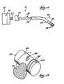
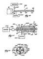
- FIG. 1is a view of a system for treating bone, which includes a injector nozzle assembly embodying features of the invention
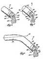
- FIG. 2is an enlarged side view of the dispensing end of one embodiment of the injector nozzle assembly shown in FIG. 1, in which the dispensing end is prebent in a desired geometry to facilitate its deployment;
- FIG. 4is an enlarged end view of the dispensing end of one embodiment of the injector nozzle assembly shown in FIG. 1, which carries a loop formed for cutting cement free from the dispensing end;
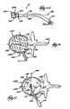
- FIG. 7is an enlarged end view of the dispensing end of one embodiment of the injector nozzle assembly shown in FIG. 1, in which the dispensing end is steerable and also carries a loop formed for cutting cement free from the dispensing end;
- FIG. 9is an enlarged end view of the dispensing end of one embodiment of the injector nozzle assembly shown in FIG. 1, which carries a prebent stylet, which is shown in a retracted and straightened condition prior to use;
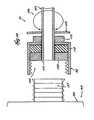
- FIG. 14is an enlarged side section view of an injector nozzle assembly which includes a rotating fitting that allows the injector tube to be rotated independent of the cement injecting tool;
- FIG. 17is a coronal view of the vertebral body shown in FIG. 16, illustrating the deployment of the injector nozzle assembly shown in FIG. 1 by postero-lateral access;
- FIGS. 19A, 19 B, and 19 Care side views of an injector nozzle assembly, which also includes index markers for ascertaining the extent to which the dispensing end is extended into the targeted treatment site, without the need for direct visualization;
- FIG. 27is a side view, with portions broken away and in section, of the injector nozzle assembly shown in FIG. 23, being operated to provide a slower, metered delivery rate of flowable material.
- FIG. 1shows the system 11 to include a tool 12 that forms a cement-receiving cavity in cancellous bone and a tool 14 , to which the assembly 10 is releasably attached to convey cement into the formed cancellous bone cavity.
- the injection nozzle assembly 10is intended to be component that can be removably connected to a conventional injection tool 14 , e.g., by a threaded connector 36 (see FIG. 2 ).
- the tool 14comprises a pistol-shaped grip, which will be referred to as a gun 22 .
- the gun 22includes an end fitment 24 , to which a cartridge 26 is removably attached, for example, by threaded screw engagement (not shown).
- the cartridge 26includes an interior, movable piston 28 .
- a ram rod 40extends within the gun 22 .
- the rod 40carries a ram disk 44 .
- the rod 40is coupled to a finger trigger 42 .
- the rod 40advances the ram disk 44 into contact with the cartridge piston 28 . Advancement of the cartridge piston 28 , in turn, pushes the bone cement 38 through the screw connector 37 into the lumen 32 of the injection tube 30 and out through the dispensing end 34 , as FIG. 1 shows.
- the injection tube 30carries steering wires 50 and 52 .
- the steering wires 50 and 52extend through side lumens, respectively 50 A and 52 A in the tube 30 and are coupled to the dispensing end 34 .
- steering wires 50 and 52are shown for the purpose of illustration, but it should be realized that more or fewer steering wires may be used.
- the steering wires 50 and 52are coupled to a steering mechanism 54 located on the proximal end of the tube 30 near the gun cartridge 26 , for manipulation by the physician.
- the steering mechanism 54comprises a rotatable wheel 56 with a control lever 55 , to which the steering wires 50 and 52 are coupled.
- Other types of steering mechanisms 54such as pull tabs or linear actuators, can be used.
- position of the control lever 55corresponds with the angular orientation of the dispensing end 34 .
- the control lever 55is located in the center position C, the dispensing end 34 is in a straightened condition C′.
- the control lever 55is moved down or clockwise (for example, to phantom line position D) the dispensing end 34 is likewise moved to phantom line position D′, and the rotation angle A 1 between position C and D generally corresponds with the deflection angle A 1 ′ between position C′ and D′.
- one embodiment of the nozzle assembly 10includes a length of wire 100 carried by the dispensing end 34 .
- the wire 100extends across the central opening 32 , forming a loop 102 for cutting loose the cement bolus 62 expelled through the lumen 32 .
- rotation of the injection tube 30rotates the dispensing end 34 and, with it, the loop 102 .
- the loop 102rotates within the expelled bolus 62 of cement adjacent the terminal end of the lumen 32 .
- Rotation of the loop 102 through 180°cuts loose the expelled cement bolus 62 from the unexpelled cement mass 64 , which resides within the dispensing end 34 .
- the loop 102integrally carried by the dispensing end 34 , creates a consistent and clean break between the expelled bolus 62 and the unexpelled mass 64 .
- the nozzle assembly 10includes two lengths of wire 126 and 128 carried by the dispensing end 34 .
- the wires 126 and 128cross over the center lumen 32 , forming two cement cutting loops 130 and 132 in the path of cement expelled by the lumen 32 .
- Rotation of the dispensing end 34 through 90°passes the two loops 64 and 66 through the cement bolus 62 , severing the cement bolus 62 from the cement mass residing in the dispensing end 34 , in the manner shown in FIG. 5 .
- the steering and cement cutting elementscan be combined.
- the nozzle assembly 10includes a length of wire 134 , which is threaded through side lumens 136 A and 136 B, which extend through the tube 30 (in the manner shown in FIG. 3 ).
- the wire 134forms an exterior loop 58 at the tip of the dispensing end 34 .
- the side lumens 136 A and 136 Bare generally diametrically spaced with respect to the center lumen 32 , so that the exterior loop 58 extends across the center lumen 32 , generally bisecting it.
- the exterior loop 58serves as a cement cutting tool, as previously described.
- FIGS. 9 to 11show an alternative embodiment of a nozzle assembly 10 , which includes a bent stylet 200 to cut loose an expelled cement bolus 62 .
- the stylet 200is slidably carried by an interior lumen 202 in the injection tube 30 .
- a locating tab 206 on the stylet 200mates with a groove or keyway 208 in the lumen 202 , to prevent rotation of the stylet 200 in the lumen 202 .
- a suitable push-pull mechanism(not shown) is accessible at the proximal end of the injection tube 30 to affect advancement and retraction of the stylet 200 in the lumen 202 .
- the distal end 204 of the stylet 200is preformed with an angle bend.
- the distal end 204When located in the lumen 202 (as FIG. 9 shows), the distal end 204 is retained in a straightened condition.
- the distal end 204assumes the preformed, bent configuration.
- the locating tab 206 and mating keyway 208orient the stylet 200 , so that, when moved free of the lumen 202 , the distal end 204 bends toward and over the central opening 32 of the tube 32 , as FIG. 10 shows.
- the distal end 204preferably extends at least half way or more across the central opening 32 of the tube 30 .
- the nozzle assembly 10includes an injection tube 30 like that shown in FIG. 2 .
- the tube 30includes a threaded connector 36 , which screws onto the connector 37 of the cement gun cartridge 26 .
- the tube 30includes a center lumen 32 to transport cement from the cartridge 26 to a distal dispensing end 34 .
- the center lumen 32does not extend axially through the tip of the distal dispensing end 34 .
- the tip of the dispensing end 34is closed and includes at least one dispensing port 180 extending at an angle from the central lumen 32 .
- the port 180opens on a side of the dispensing end 34 .
- the cement bolus 62is expressed through the side dispensing port 180 , and not through the distal tip of the dispensing end 34 .
- rotation of the dispensing end 34(indicated by arrow 182 ) moves the dispensing port 180 along an arc transversely of and away from the cement bolus 62 .
- the transverse movement of the side dispensing port 180 away from the bolus 32severs the bolus 32 from the cement mass residing in the center lumen 32 .
- the dispensing end 34 of the injection tube 30can, if desired, be preformed with a normal deflection, as previously described, to offset the dispensing end 34 with respect to the axis 46 of the injection tube 30 .
- the tube 30can also carry steering wires 50 and 52 , as shown in FIG. 3, to steer the dispensing end 34 .
- the threaded connector 36which releasably couples the injection tube 30 to the screw connector 37 on the front end of the cartridge 26 of the cement gun 22 , can include a fitting 104 that permits rotation of the injection tube 30 relative to the connector 36 and the gun 22 .
- the rotating fitting 104includes an adaptor 108 carried for rotation within the connector 36 .
- the proximal end 110 of the injector tube 30is secured to the adaptor 108 for common rotation.
- a retaining ring 112 outside the connector 36surrounds tube 30 , allowing its rotation but otherwise restraining rearward axial movement.
- An o-ring 114is contained between the adaptor 108 and the end wall of the connector 36 . The o-ring 114 restrains forward axial movement of the tube 30 , while also preventing leakage of cement.
- the rotating fitting 104permits the physician to rotate the injection tube 30 with one hand, and thereby rotate the nozzle 34 (as arrows 106 show in FIG. 14 ), while holding the gun 22 stationary in another hand.
- the injection tube 30can carry a hub or grip 115 to facilitate rotation.
- the rotating fitting 104simplifies handling and manipulation of the cement injection tool 14 during rotation of the injection tube 30 .
- the physicianis able to rotate the injection tube 30 , causing the one or more cement cutting loops carried by the rotating dispensing end 34 to cut loose an expelled cement bolus 62 (as shown in FIGS. 4 and 5, 9 and 10 , and 12 and 13 ), without rotating the gun 22 itself.
- rotation of the tube 30further helps locate the dispensing end 34 in the desired position, again without the need to rotate the gun 22 .
- the rotating fitting 104can include indicia to gauge orientation or rotation of the injection tube 30 .
- the indiciaincludes an index mark 210 scribed on the connector 36 , which aligns with an index mark 212 scribed on the proximal end of the injection tube 30 . Alignment of the marks 210 and 212 places the dispensing end 34 in a particular, preestablished orientation.
- alignment of the marks 210 and 212can designate that the deflection is to the right of the main axis 46 .
- the index mark 210can also include a visual or tactile identifier (for example, a raised letter “R” in FIG. 15) to further aid the physician in ascertaining the orientation.
- the fitting 104can also include additional auxiliary index marks (two of which 214 and 216 are shown in FIG. 15) and associated visual or tactile identifiers (respectively, “U” and “D”). Alignment of the mark 212 with auxiliary mark 214 indicates that the deflection orients the dispensing end 34 upward. Likewise, alignment of the mark 212 with auxiliary mark 216 indicates that the deflection orients the dispensing end 34 downward.
- Another auxiliary mark and associated identifier(not shown), located diametrically opposite to the mark 210 , can also indicate a left orientation of the deflected dispensing end 34 .
- the alignment of the index mark 212 with the index marks 210 , 214 , and 216allows the physician to remotely orient the deflected end 34 in a desired way, without reliance upon x-ray or other internal visualization technique. Tracking the rotation of the index mark 212 relative to one or more of the index marks 210 , 214 , or 216 also allows the physician to gauge the rotation of the injection tube 30 , to achieve the degree of rotation necessary to cut the cement bolus 62 loose.
- alignment of the marks 210 and 212can designate that the steering wires 50 and 52 extend in a particular vertical or horizontal plane. With this orientation known, the physician can operate the steering mechanism 56 to achieve the desired bending action, without reliance upon x-ray or other form of internal visualization. Relative movement of the index marks also allows the physician to monitor the extent of rotation of the injection tube 30 when cutting the cement bolus 62 loose.
- alignment of the marks 210 and 212can designate the orientation of the dispensing port 180 , either left, right, up, or down. Relative movement of the index marks also allows the physician to monitor the extent of rotation of the injection tube 30 when cutting the cement bolus 62 loose.
- markerscan be used to allow the physician to visualize the location of the dispensing end 34 within the targeted treatment area.
- FIG. 16shows in coronal (top) view. It should be appreciated, however, the nozzle assembly 10 is not limited in its application to vertebrae. The system 10 can be deployed equally as well in long bones and other bone types.
- the vertebra 150includes a vertebral body 152 , which extends on the anterior (i.e., front or chest) side of the vertebra 150 .
- the vertebral body 152includes an exterior formed from compact cortical bone 158 .
- the cortical bone 158encloses an interior volume of reticulated cancellous, or spongy, bone 160 (also called medullary bone or trabecular bone).
- the vertebral body 152is in the shape of an oval disk, which is generally symmetric about an anterior-posterior axis 154 and a mid-lateral axis 156 .
- the axes 154 and 156intersect in the middle region or geometric center of the body 152 , which is designated MR in the drawings.
- access to the interior volume of the vertebral body 152can be achieved. e.g., by drilling an access portal 162 through a side of the vertebral body 152 , which is called a postero-lateral approach.
- the portal 162 for the postero-lateral approachenters at a posterior side of the body 152 and extends at angle forwardly toward the anterior of the body 152 .
- the portal 162can be performed either with a closed, minimally invasive procedure or with an open procedure.
- a guide sheath 166is located in the access portal 162 .
- the tool 12is introduced through the guide sheath 166 , with the expandable body 20 collapsed.
- the physicianconveys a pressurized fluid into the body 20 to expand it.
- the fluidis preferably radio-opaque to facilitate visualization.
- RenografinTM contract mediacan be used for this purpose.
- the body 20is preferably left inflated for an appropriate waiting period, for example, three to five minutes, to allow coagulation inside the vertebral body 152 .
- an appropriate waiting periodfor example, three to five minutes, to allow coagulation inside the vertebral body 152 .
- the physiciancollapses the body 20 and removes it.
- the formed cavity 164remains in the interior volume of the vertebral body 152 .
- the second tool 14is now readied for deployment.
- the physiciandirects the injection tube 30 through the guide sheath 166 into the formed cavity 164 .
- dispensing end 34If the dispensing end 34 is normally biased into a bent condition (as exemplified in FIG. 2 ), passage through the guide sheath 166 overcomes the bias and straightens out the dispensing end 34 . Once free of the guide sheath 166 , the dispensing end 34 returns to its normally biased condition.
- FIG. 19Bshows, subsequent movement of the tube 30 in the sheath 166 brings the marker 218 (l) into alignment with the proximal edge 220 .
- This alignmentindicates that the tip of the dispensing end 34 projects beyond the distal edge 222 by a first, predetermined distance D 1 .
- the physicianmay selectively bend the dispensing end 34 under radiological visualization provided by the markers 68 . In this way, the physician can steer the dispensing end 34 into the desired position or positions within the cavity 164 before or during injection of cement 38 .
- the markers 212 / 210 , 214 , and 216 on the fitting 104aid the steering process (see FIG. 15 ), without active internal visualization.
- the physicianobserves the progress of the injection radiologically using the markers 68 , positioning the dispensing end 34 by rotation or steering, or both, as just described.
- the physicianflows material 38 into the cavity 164 , until the material 38 reaches the interior end of the guide sheath 166 .
- the dispensing end 34carries one or more exterior loops (as exemplified in FIGS. 4 to 10 ), or a side dispensing port 180 (as exemplified in FIGS. 12 and 13 )
- rotation of the dispensing end 34will cleanly sever the injected cement bolus residing in the cavity 164 from the unexpelled cement residing within the dispensing end 34 (as FIGS. 4 and 5 and FIGS. 12 and 13 show).
- cement residing in the cavity 164will not be inadvertently drawn out of the cavity 164 upon withdrawal of the dispensing end 34 .
- Rotation of the dispensing end 34 to sever the material bolusalso avoids the formation of sharp pedicles in the material bolus, which could irritate surrounding tissue.
- the markers 212 / 210 , 214 , and 216 on the fitting 104aid in monitoring the extent of rotation, without active internal visualization
- FIG. 18shows in a lateral view
- access into the interior volume of a vertebral body 152can also be accomplished by drilling an access portal 168 through either pedicle 170 .
- Thisis called a transpedicular approach.
- the access portal 170 for a transpedicular approachenters at the top of the vertebral body 152 , where the pedicle 170 is relatively thin, and extends at an angle downward toward the bottom of the vertebral body 152 to enter the interior volume.
- FIG. 20shows a system 240 for cooling the nozzle assembly 10 during passage of the cement 38 through the dispensing end 34 .
- the system 240includes the injection tube 30 , which is releasably coupled to the front end of the cartridge 26 by the threaded connector 36 , as previously described.
- the tube 30includes the center lumen 30 , through which cement 38 conveyed from the cartridge 26 passes.
- the proximal ends of the lumens B in each set 242 A/B; 244 A/B; 246 A/B; and 248 A/Bcommunicate with waste 252 .
- the lumen B of each set 242 A/B; 244 A/B; 246 A/B; and 248 A/Bthereby comprises a return path for the cooling fluid.
- the cooling fluidis at a desired temperature, which is cooler than the threshold temperature of the cement 38 .
- the source fluidcan comprise tap water at a temperature of about 68° F. (20° C.).
- the pump 254conveys cooling fluid from the source 250 through the inlet paths 242 A, 244 A, 246 B, and 248 B.
- the return paths 242 B, 244 B, 246 B, and 248 Bcarry the cooling fluid to waste 252 .
- the circulation of cooling fluid in the tube 30 along the center lumen 32dissipates heat generated by the curing cement 38 , to mediate the temperature increase in the curing cement 38 .
- the circulation of cooling fluidthereby keeps the curing cement 38 in the center lumen 32 in a viscous flowing condition for a longer period of time.
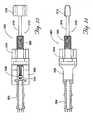
- the assembly 300comprises a syringe body 304 coupled to a syringe handle 306 .
- a volume of flowable material 302is loaded into the syringe body 304 (see FIGS. 26 and 27 ).
- a syringe plunger 308is carried in a plunger chamber 310 formed in the interior of the syringe handle 306 .
- the syringe plunger 308axially advances through the syringe body 304 , thereby expelling the flowable material 302 out the distal end of the syringe body 304 (as FIGS. 26 and 27 show).
- the syringe handle 306 and syringe body 304can comprise, e.g., formed plastic or metal parts.
- the syringe handle 306can be formed to possess different shapes and sizes. It is desired that the handle 306 is sized to fit comfortably in the hand of an operator.
- the ability to start and stop both large volume flow and metered, smaller volume flowmakes it possible to rapidly respond to in situ flow conditions, to thereby prevent or minimize the flow of material 302 under pressure through cracks, openings, or voids in cortical bone, in a process called “extravazation.”
- the operation of the plunger advancement mechanism 312 to achieve a variable rate of deliverycan be implemented in various ways.
- the plunger advancement mechanism 312responds to the application of rotational force to advance the syringe plunger 308 .
- rotatable first and second actuators or control knobs 314 and 316are carried at the proximal end of the syringe handle 306 .
- the plunger advancement mechanism 312is operated manually. It should be appreciated that the plunger advancement mechanism can be operated by means of an electric motor or the like.
- the assembly 300 shown in FIGS. 23 to 27can be used to convey material 310 into a cavity created in cancellous bone by an expandable structure, as earlier described and as shown in FIGS. 16 and 17.
- the assembly 300may also be used in association with a vertebroplasty procedure, which injects cement under pressure into a vertebral body, without prior formation of a cavity.
- the syringe handle 306(which can be made of polycarbonate) measures about 3.9 inches in length and 2.6 inches in width.
- the syringe body 304(which also can be made of polycarbonate) measures about 5.1 inches in overall length, with an interior lumen having an inside diameter of about 0.5 inch.
- the first control knob 314(which can be made from CelconTM plastic material) is shaped round and has a diameter of about 2.5 inches.
- the fast advancement screw 320(which can also be made from CelconTM plastic material) has a length of about 4.5 inches and an outside thread diameter of about 0.75 inch. The internal threads extend for a distance of about 0.75 inch.
- the slow advancement screw 318extends from the second control knob 316 for a length of about 9.35 inches and has an outside thread diameter of about 3 ⁇ 8 inch.
- the second control knob 316is elliptical in shape, measuring about 2.0 inches along its major axis, about 0.625 inch along its minor axis, and about 1.5 inches in height.
Landscapes
- Health & Medical Sciences (AREA)
- Orthopedic Medicine & Surgery (AREA)
- Life Sciences & Earth Sciences (AREA)
- Surgery (AREA)
- Public Health (AREA)
- Engineering & Computer Science (AREA)
- Biomedical Technology (AREA)
- Heart & Thoracic Surgery (AREA)
- Animal Behavior & Ethology (AREA)
- General Health & Medical Sciences (AREA)
- Veterinary Medicine (AREA)
- Medical Informatics (AREA)
- Molecular Biology (AREA)
- Nuclear Medicine, Radiotherapy & Molecular Imaging (AREA)
- Fluid Mechanics (AREA)
- Physics & Mathematics (AREA)
- Transplantation (AREA)
- Physical Education & Sports Medicine (AREA)
- Cardiology (AREA)
- Oral & Maxillofacial Surgery (AREA)
- Vascular Medicine (AREA)
- Surgical Instruments (AREA)
- Prostheses (AREA)
- Infusion, Injection, And Reservoir Apparatuses (AREA)
- Media Introduction/Drainage Providing Device (AREA)
Abstract
Description
Claims (11)
Priority Applications (5)
| Application Number | Priority Date | Filing Date | Title |
|---|---|---|---|
| US09/893,298US6645213B2 (en) | 1997-08-13 | 2001-06-27 | Systems and methods for injecting flowable materials into bones |
| US10/630,519US7731720B2 (en) | 1997-08-13 | 2003-07-30 | Systems and methods for injecting flowable materials into bones |
| US11/528,160US7704256B2 (en) | 1997-08-13 | 2006-09-27 | Systems and methods for injecting flowable materials into bones |
| US11/789,243US7887543B2 (en) | 1997-08-13 | 2007-04-24 | Systems and methods for injecting flowable materials into bones |
| US12/718,415US7972340B2 (en) | 1997-08-13 | 2010-03-05 | Systems and methods for injecting flowable materials into bones |
Applications Claiming Priority (4)
| Application Number | Priority Date | Filing Date | Title |
|---|---|---|---|
| US08/910,809US6048346A (en) | 1997-08-13 | 1997-08-13 | Systems and methods for injecting flowable materials into bones |
| US09/496,987US6719761B1 (en) | 1997-08-13 | 2000-02-02 | System and methods for injecting flowable materials into bones |
| US21466600P | 2000-06-27 | 2000-06-27 | |
| US09/893,298US6645213B2 (en) | 1997-08-13 | 2001-06-27 | Systems and methods for injecting flowable materials into bones |
Related Parent Applications (1)
| Application Number | Title | Priority Date | Filing Date |
|---|---|---|---|
| US09/496,987Continuation-In-PartUS6719761B1 (en) | 1997-08-13 | 2000-02-02 | System and methods for injecting flowable materials into bones |
Related Child Applications (1)
| Application Number | Title | Priority Date | Filing Date |
|---|---|---|---|
| US10/630,519DivisionUS7731720B2 (en) | 1997-08-13 | 2003-07-30 | Systems and methods for injecting flowable materials into bones |
Publications (2)
| Publication Number | Publication Date |
|---|---|
| US20020049448A1 US20020049448A1 (en) | 2002-04-25 |
| US6645213B2true US6645213B2 (en) | 2003-11-11 |
Family
ID=22799980
Family Applications (5)
| Application Number | Title | Priority Date | Filing Date |
|---|---|---|---|
| US09/893,298Expired - Fee RelatedUS6645213B2 (en) | 1997-08-13 | 2001-06-27 | Systems and methods for injecting flowable materials into bones |
| US10/630,519Expired - Fee RelatedUS7731720B2 (en) | 1997-08-13 | 2003-07-30 | Systems and methods for injecting flowable materials into bones |
| US11/528,160Expired - Fee RelatedUS7704256B2 (en) | 1997-08-13 | 2006-09-27 | Systems and methods for injecting flowable materials into bones |
| US11/789,243Expired - Fee RelatedUS7887543B2 (en) | 1997-08-13 | 2007-04-24 | Systems and methods for injecting flowable materials into bones |
| US12/718,415Expired - Fee RelatedUS7972340B2 (en) | 1997-08-13 | 2010-03-05 | Systems and methods for injecting flowable materials into bones |
Family Applications After (4)
| Application Number | Title | Priority Date | Filing Date |
|---|---|---|---|
| US10/630,519Expired - Fee RelatedUS7731720B2 (en) | 1997-08-13 | 2003-07-30 | Systems and methods for injecting flowable materials into bones |
| US11/528,160Expired - Fee RelatedUS7704256B2 (en) | 1997-08-13 | 2006-09-27 | Systems and methods for injecting flowable materials into bones |
| US11/789,243Expired - Fee RelatedUS7887543B2 (en) | 1997-08-13 | 2007-04-24 | Systems and methods for injecting flowable materials into bones |
| US12/718,415Expired - Fee RelatedUS7972340B2 (en) | 1997-08-13 | 2010-03-05 | Systems and methods for injecting flowable materials into bones |
Country Status (8)
| Country | Link |
|---|---|
| US (5) | US6645213B2 (en) |
| EP (1) | EP1294324A1 (en) |
| JP (1) | JP2004500963A (en) |
| KR (2) | KR100889414B1 (en) |
| CN (1) | CN1191042C (en) |
| AU (1) | AU2001271440A1 (en) |
| CA (1) | CA2413325A1 (en) |
| WO (1) | WO2002000143A1 (en) |
Cited By (149)
| Publication number | Priority date | Publication date | Assignee | Title |
|---|---|---|---|---|
| US20020010472A1 (en)* | 2000-06-30 | 2002-01-24 | Kuslich Stephen D. | Tool to direct bone replacement material |
| US20040133211A1 (en)* | 2002-10-03 | 2004-07-08 | Raskin Keith B. | Radially ported needle for delivering bone graft material and method of use |
| US20050031578A1 (en)* | 2002-03-22 | 2005-02-10 | Doctor's Research Group, Inc. | Methods of performing medical procedures which promote bone growth, compositions which promote bone growth, and methods of making such compositions |
| US20050124999A1 (en)* | 2003-10-31 | 2005-06-09 | Teitelbaum George P. | Device and method for radial delivery of a structural element |
| US6923813B2 (en) | 2003-09-03 | 2005-08-02 | Kyphon Inc. | Devices for creating voids in interior body regions and related methods |
| US20050209601A1 (en)* | 2004-03-22 | 2005-09-22 | Disc Dynamics, Inc. | Multi-stage biomaterial injection system for spinal implants |
| US20050220771A1 (en)* | 2002-03-22 | 2005-10-06 | Doctor's Research Group, Inc. | Methods of performing medical procedures that promote bone growth, methods of making compositions that promote bone growth, and apparatus for use in such methods |
| US20050222538A1 (en)* | 2004-03-30 | 2005-10-06 | Sdgi Holdings, Inc. | Surgical system for delivery of viscous fluids |
| US20050228397A1 (en)* | 1998-08-14 | 2005-10-13 | Malandain Hugues F | Cavity filling device |
| US20060184192A1 (en)* | 2005-02-11 | 2006-08-17 | Markworth Aaron D | Systems and methods for providing cavities in interior body regions |
| US20060265076A1 (en)* | 2005-05-03 | 2006-11-23 | Disc Dynamics, Inc. | Catheter holder for spinal implant |
| US20060264964A1 (en)* | 2005-05-19 | 2006-11-23 | Sdgi Holdings, Inc. | Graft syringe assembly |
| US20070010844A1 (en)* | 2005-07-08 | 2007-01-11 | Gorman Gong | Radiopaque expandable body and methods |
| US20070010848A1 (en)* | 2005-07-11 | 2007-01-11 | Andrea Leung | Systems and methods for providing cavities in interior body regions |
| US20070010824A1 (en)* | 2005-07-11 | 2007-01-11 | Hugues Malandain | Products, systems and methods for delivering material to bone and other internal body parts |
| US20070010845A1 (en)* | 2005-07-08 | 2007-01-11 | Gorman Gong | Directionally controlled expandable device and methods for use |
| US20070006692A1 (en)* | 2005-07-11 | 2007-01-11 | Phan Christopher U | Torque limiting device |
| US20070055201A1 (en)* | 2005-07-11 | 2007-03-08 | Seto Christine L | Systems and methods for providing cavities in interior body regions |
| US20070055276A1 (en)* | 2005-07-11 | 2007-03-08 | Edidin Avram A | Systems and methods for inserting biocompatible filler materials in interior body regions |
| US20070060933A1 (en)* | 2005-07-11 | 2007-03-15 | Meera Sankaran | Curette heads |
| US20070118142A1 (en)* | 2005-11-18 | 2007-05-24 | Krueger John A | Device, system and method for delivering a curable material into bone |
| US20070129669A1 (en)* | 2003-05-21 | 2007-06-07 | Crosstrees Medical, Inc. | Extractable filler for inserting medicine into animal tissue |
| US20070129670A1 (en)* | 2003-09-29 | 2007-06-07 | Crosstrees Medical, Inc. | Extractable filler for inserting medicine into vertebral body |
| US20070142765A1 (en)* | 2003-05-21 | 2007-06-21 | Crosstrees Medical, Inc. | Extractable filler for inserting medicine into animal tissue |
| US20070142842A1 (en)* | 2005-11-18 | 2007-06-21 | Krueger John A | Device, system and method for delivering a curable material into bone |
| US20070162061A1 (en)* | 2005-11-04 | 2007-07-12 | X-Sten, Corp. | Tissue excision devices and methods |
| US20070233258A1 (en)* | 2006-02-28 | 2007-10-04 | Zimmer Spine, Inc. | Vertebroplasty- device and method |
| US20070260257A1 (en)* | 2005-07-11 | 2007-11-08 | Phan Christopher U | Surgical device having interchangeable components and methods of use |
| US20080009876A1 (en)* | 2006-07-07 | 2008-01-10 | Meera Sankaran | Medical device with expansion mechanism |
| US20080071284A1 (en)* | 2004-04-26 | 2008-03-20 | Beat Lechmann | Device for Manipulating and Supplying Hollow or Intervertebral or Disk Prosthesis With Flowable Osteocementum |
| US20080086142A1 (en)* | 2006-10-06 | 2008-04-10 | Kohm Andrew C | Products and Methods for Delivery of Material to Bone and Other Internal Body Parts |
| US20080133015A1 (en)* | 2004-04-26 | 2008-06-05 | Beat Lechmann | Intervertebral Prosthesis or Disk Prosthesis |
| US20080243249A1 (en)* | 2007-03-30 | 2008-10-02 | Kohm Andrew C | Devices for multipoint emplacement in a body part and methods of use of such devices |
| US20090149860A1 (en)* | 2005-07-07 | 2009-06-11 | Scribner Robert M | Device for delivery of bone void filling materials |
| US20090254132A1 (en)* | 2005-07-07 | 2009-10-08 | Scribner Robert M | Devices and methods for the treatment of bone fracture |
| USD610259S1 (en) | 2008-10-23 | 2010-02-16 | Vertos Medical, Inc. | Tissue modification device |
| US7666227B2 (en) | 2005-08-16 | 2010-02-23 | Benvenue Medical, Inc. | Devices for limiting the movement of material introduced between layers of spinal tissue |
| USD611146S1 (en) | 2008-10-23 | 2010-03-02 | Vertos Medical, Inc. | Tissue modification device |
| US20100160921A1 (en)* | 2008-12-19 | 2010-06-24 | Arthrocare Corporation | Cancellous bone displacement system and methods of use |
| USD619253S1 (en) | 2008-10-23 | 2010-07-06 | Vertos Medical, Inc. | Tissue modification device |
| US7749230B2 (en) | 2004-09-02 | 2010-07-06 | Crosstrees Medical, Inc. | Device and method for distraction of the spinal disc space |
| USD619252S1 (en) | 2008-10-23 | 2010-07-06 | Vertos Medical, Inc. | Tissue modification device |
| USD621939S1 (en) | 2008-10-23 | 2010-08-17 | Vertos Medical, Inc. | Tissue modification device |
| US7879103B2 (en) | 2005-04-15 | 2011-02-01 | Musculoskeletal Transplant Foundation | Vertebral disc repair |
| US20110028981A1 (en)* | 2009-07-29 | 2011-02-03 | Warsaw Orthopedic, Inc. | Bone graft measuring apparatus and method of use |
| US7896879B2 (en) | 2004-07-29 | 2011-03-01 | Vertos Medical, Inc. | Spinal ligament modification |
| US20110054416A1 (en)* | 2007-09-14 | 2011-03-03 | Hollowell Daniel R | Material control device for inserting material into a targeted anatomical region |
| USD635671S1 (en) | 2008-10-23 | 2011-04-05 | Vertos Medical, Inc. | Tissue modification device |
| US7942830B2 (en) | 2006-05-09 | 2011-05-17 | Vertos Medical, Inc. | Ipsilateral approach to minimally invasive ligament decompression procedure |
| US20110125088A1 (en)* | 2004-03-31 | 2011-05-26 | Cook Incorporated | Apparatus for an improved high pressure medicinal dispenser |
| US7959683B2 (en) | 2006-07-25 | 2011-06-14 | Musculoskeletal Transplant Foundation | Packed demineralized cancellous tissue forms for disc nucleus augmentation, restoration, or replacement and methods of implantation |
| WO2011065979A3 (en)* | 2009-11-30 | 2011-11-17 | Dartmouth Medical Research Limited | Adhesive delivery devices, systems and methods |
| US8066713B2 (en) | 2003-03-31 | 2011-11-29 | Depuy Spine, Inc. | Remotely-activated vertebroplasty injection device |
| US8105236B2 (en) | 2005-07-11 | 2012-01-31 | Kyphon Sarl | Surgical access device, system, and methods of use |
| US8128632B2 (en) | 2006-05-22 | 2012-03-06 | Orthovita, Inc. | Delivery of multicomponent compositions |
| US8142462B2 (en) | 2004-05-28 | 2012-03-27 | Cavitech, Llc | Instruments and methods for reducing and stabilizing bone fractures |
| US8163018B2 (en) | 2006-02-14 | 2012-04-24 | Warsaw Orthopedic, Inc. | Treatment of the vertebral column |
| US8221420B2 (en) | 2009-02-16 | 2012-07-17 | Aoi Medical, Inc. | Trauma nail accumulator |
| US20120239050A1 (en)* | 2005-11-18 | 2012-09-20 | Linderman Evan D | Multistate-curvature device and method for delivering a curable material into bone |
| US8277506B2 (en) | 2008-06-24 | 2012-10-02 | Carefusion 2200, Inc. | Method and structure for stabilizing a vertebral body |
| USD669168S1 (en) | 2005-11-18 | 2012-10-16 | Carefusion 2200, Inc. | Vertebral augmentation needle |
| US8353911B2 (en) | 2007-05-21 | 2013-01-15 | Aoi Medical, Inc. | Extendable cutting member |
| US8360629B2 (en) | 2005-11-22 | 2013-01-29 | Depuy Spine, Inc. | Mixing apparatus having central and planetary mixing elements |
| US8361078B2 (en) | 2003-06-17 | 2013-01-29 | Depuy Spine, Inc. | Methods, materials and apparatus for treating bone and other tissue |
| US8366773B2 (en) | 2005-08-16 | 2013-02-05 | Benvenue Medical, Inc. | Apparatus and method for treating bone |
| US8415407B2 (en) | 2004-03-21 | 2013-04-09 | Depuy Spine, Inc. | Methods, materials, and apparatus for treating bone and other tissue |
| US8454617B2 (en) | 2005-08-16 | 2013-06-04 | Benvenue Medical, Inc. | Devices for treating the spine |
| US8535327B2 (en) | 2009-03-17 | 2013-09-17 | Benvenue Medical, Inc. | Delivery apparatus for use with implantable medical devices |
| US8535380B2 (en) | 2010-05-13 | 2013-09-17 | Stout Medical Group, L.P. | Fixation device and method |
| US8579908B2 (en)* | 2003-09-26 | 2013-11-12 | DePuy Synthes Products, LLC. | Device for delivering viscous material |
| US8591583B2 (en) | 2005-08-16 | 2013-11-26 | Benvenue Medical, Inc. | Devices for treating the spine |
| US8603096B2 (en) | 2011-06-10 | 2013-12-10 | Globus Medical, Inc. | Biomaterial dispensing device |
| US20140074226A1 (en)* | 2011-01-31 | 2014-03-13 | St. Jude Medical, Inc | Anti-rotation locking feature |
| US8696671B2 (en) | 2005-07-29 | 2014-04-15 | Vertos Medical Inc. | Percutaneous tissue excision devices |
| US8708955B2 (en) | 2008-06-02 | 2014-04-29 | Loma Vista Medical, Inc. | Inflatable medical devices |
| US8709042B2 (en) | 2004-09-21 | 2014-04-29 | Stout Medical Group, LP | Expandable support device and method of use |
| US8801800B2 (en) | 2009-11-20 | 2014-08-12 | Zimmer Knee Creations, Inc. | Bone-derived implantable devices and tool for subchondral treatment of joint pain |
| US8814873B2 (en) | 2011-06-24 | 2014-08-26 | Benvenue Medical, Inc. | Devices and methods for treating bone tissue |
| US8821504B2 (en) | 2009-11-20 | 2014-09-02 | Zimmer Knee Creations, Inc. | Method for treating joint pain and associated instruments |
| US8827981B2 (en) | 2007-11-16 | 2014-09-09 | Osseon Llc | Steerable vertebroplasty system with cavity creation element |
| US8864768B2 (en) | 2009-11-20 | 2014-10-21 | Zimmer Knee Creations, Inc. | Coordinate mapping system for joint treatment |
| US8906032B2 (en) | 2009-11-20 | 2014-12-09 | Zimmer Knee Creations, Inc. | Instruments for a variable angle approach to a joint |
| US8950929B2 (en) | 2006-10-19 | 2015-02-10 | DePuy Synthes Products, LLC | Fluid delivery system |
| US8992541B2 (en) | 2003-03-14 | 2015-03-31 | DePuy Synthes Products, LLC | Hydraulic device for the injection of bone cement in percutaneous vertebroplasty |
| US9033987B2 (en) | 2009-11-20 | 2015-05-19 | Zimmer Knee Creations, Inc. | Navigation and positioning instruments for joint repair |
| US9050112B2 (en) | 2011-08-23 | 2015-06-09 | Flexmedex, LLC | Tissue removal device and method |
| US9119639B2 (en) | 2011-08-09 | 2015-09-01 | DePuy Synthes Products, Inc. | Articulated cavity creator |
| US9149286B1 (en) | 2010-11-12 | 2015-10-06 | Flexmedex, LLC | Guidance tool and method for use |
| US9155580B2 (en) | 2011-08-25 | 2015-10-13 | Medos International Sarl | Multi-threaded cannulated bone anchors |
| US9168078B2 (en) | 2009-11-10 | 2015-10-27 | Carefusion 2200, Inc. | Apparatus and method for stylet-guided vertebral augmentation |
| US9220554B2 (en) | 2010-02-18 | 2015-12-29 | Globus Medical, Inc. | Methods and apparatus for treating vertebral fractures |
| US9259257B2 (en) | 2009-11-20 | 2016-02-16 | Zimmer Knee Creations, Inc. | Instruments for targeting a joint defect |
| US9265548B2 (en) | 2008-10-30 | 2016-02-23 | DePuy Synthes Products, Inc. | Systems and methods for delivering bone cement to a bone anchor |
| US9271835B2 (en) | 2009-11-20 | 2016-03-01 | Zimmer Knee Creations, Inc. | Implantable devices for subchondral treatment of joint pain |
| US9326806B2 (en) | 2003-09-02 | 2016-05-03 | Crosstrees Medical, Inc. | Devices and methods for the treatment of bone fracture |
| US9381024B2 (en) | 2005-07-31 | 2016-07-05 | DePuy Synthes Products, Inc. | Marked tools |
| US9439693B2 (en) | 2013-02-01 | 2016-09-13 | DePuy Synthes Products, Inc. | Steerable needle assembly for use in vertebral body augmentation |
| US9510885B2 (en) | 2007-11-16 | 2016-12-06 | Osseon Llc | Steerable and curvable cavity creation system |
| US9592119B2 (en) | 2010-07-13 | 2017-03-14 | C.R. Bard, Inc. | Inflatable medical devices |
| US9642932B2 (en) | 2006-09-14 | 2017-05-09 | DePuy Synthes Products, Inc. | Bone cement and methods of use thereof |
| US9717544B2 (en) | 2009-11-20 | 2017-08-01 | Zimmer Knee Creations, Inc. | Subchondral treatment of joint pain |
| US9763784B2 (en) | 2011-01-31 | 2017-09-19 | St. Jude Medical, Inc. | Tool for the adjustment of a prosthetic anatomical device |
| US9770339B2 (en) | 2005-07-14 | 2017-09-26 | Stout Medical Group, L.P. | Expandable support device and method of use |
| US9788963B2 (en) | 2003-02-14 | 2017-10-17 | DePuy Synthes Products, Inc. | In-situ formed intervertebral fusion device and method |
| US9918767B2 (en) | 2005-08-01 | 2018-03-20 | DePuy Synthes Products, Inc. | Temperature control system |
| US10028834B2 (en) | 2011-01-31 | 2018-07-24 | St. Jude Medical, Inc. | Adjustable prosthetic anatomical device holder and handle for the implantation of an annuloplasty ring |
| US10070968B2 (en) | 2010-08-24 | 2018-09-11 | Flexmedex, LLC | Support device and method for use |
| US10085783B2 (en) | 2013-03-14 | 2018-10-02 | Izi Medical Products, Llc | Devices and methods for treating bone tissue |
| US10188273B2 (en) | 2007-01-30 | 2019-01-29 | Loma Vista Medical, Inc. | Biological navigation device |
| US10188436B2 (en) | 2010-11-09 | 2019-01-29 | Loma Vista Medical, Inc. | Inflatable medical devices |
| US10231846B2 (en) | 2016-08-19 | 2019-03-19 | Stryker European Holdings I, Llc | Bone graft delivery loading assembly |
| US10285820B2 (en) | 2008-11-12 | 2019-05-14 | Stout Medical Group, L.P. | Fixation device and method |
| US10463380B2 (en) | 2016-12-09 | 2019-11-05 | Dfine, Inc. | Medical devices for treating hard tissues and related methods |
| US10478241B2 (en) | 2016-10-27 | 2019-11-19 | Merit Medical Systems, Inc. | Articulating osteotome with cement delivery channel |
| US10624652B2 (en) | 2010-04-29 | 2020-04-21 | Dfine, Inc. | System for use in treatment of vertebral fractures |
| US10660656B2 (en) | 2017-01-06 | 2020-05-26 | Dfine, Inc. | Osteotome with a distal portion for simultaneous advancement and articulation |
| US10758289B2 (en) | 2006-05-01 | 2020-09-01 | Stout Medical Group, L.P. | Expandable support device and method of use |
| US10888433B2 (en) | 2016-12-14 | 2021-01-12 | DePuy Synthes Products, Inc. | Intervertebral implant inserter and related methods |
| US10940014B2 (en) | 2008-11-12 | 2021-03-09 | Stout Medical Group, L.P. | Fixation device and method |
| US10940016B2 (en) | 2017-07-05 | 2021-03-09 | Medos International Sarl | Expandable intervertebral fusion cage |
| US10966840B2 (en) | 2010-06-24 | 2021-04-06 | DePuy Synthes Products, Inc. | Enhanced cage insertion assembly |
| US10973652B2 (en) | 2007-06-26 | 2021-04-13 | DePuy Synthes Products, Inc. | Highly lordosed fusion cage |
| US11026744B2 (en) | 2016-11-28 | 2021-06-08 | Dfine, Inc. | Tumor ablation devices and related methods |
| US11197681B2 (en) | 2009-05-20 | 2021-12-14 | Merit Medical Systems, Inc. | Steerable curvable vertebroplasty drill |
| US11273050B2 (en) | 2006-12-07 | 2022-03-15 | DePuy Synthes Products, Inc. | Intervertebral implant |
| US11344424B2 (en) | 2017-06-14 | 2022-05-31 | Medos International Sarl | Expandable intervertebral implant and related methods |
| US11426290B2 (en) | 2015-03-06 | 2022-08-30 | DePuy Synthes Products, Inc. | Expandable intervertebral implant, system, kit and method |
| US11426286B2 (en) | 2020-03-06 | 2022-08-30 | Eit Emerging Implant Technologies Gmbh | Expandable intervertebral implant |
| US11446156B2 (en) | 2018-10-25 | 2022-09-20 | Medos International Sarl | Expandable intervertebral implant, inserter instrument, and related methods |
| US11446155B2 (en) | 2017-05-08 | 2022-09-20 | Medos International Sarl | Expandable cage |
| US11452607B2 (en) | 2010-10-11 | 2022-09-27 | DePuy Synthes Products, Inc. | Expandable interspinous process spacer implant |
| US11497619B2 (en) | 2013-03-07 | 2022-11-15 | DePuy Synthes Products, Inc. | Intervertebral implant |
| US11510723B2 (en) | 2018-11-08 | 2022-11-29 | Dfine, Inc. | Tumor ablation device and related systems and methods |
| US11510788B2 (en) | 2016-06-28 | 2022-11-29 | Eit Emerging Implant Technologies Gmbh | Expandable, angularly adjustable intervertebral cages |
| US11596522B2 (en) | 2016-06-28 | 2023-03-07 | Eit Emerging Implant Technologies Gmbh | Expandable and angularly adjustable intervertebral cages with articulating joint |
| US11602438B2 (en) | 2008-04-05 | 2023-03-14 | DePuy Synthes Products, Inc. | Expandable intervertebral implant |
| US11607321B2 (en) | 2009-12-10 | 2023-03-21 | DePuy Synthes Products, Inc. | Bellows-like expandable interbody fusion cage |
| US11612491B2 (en) | 2009-03-30 | 2023-03-28 | DePuy Synthes Products, Inc. | Zero profile spinal fusion cage |
| US11654033B2 (en) | 2010-06-29 | 2023-05-23 | DePuy Synthes Products, Inc. | Distractible intervertebral implant |
| US11737881B2 (en) | 2008-01-17 | 2023-08-29 | DePuy Synthes Products, Inc. | Expandable intervertebral implant and associated method of manufacturing the same |
| US11752009B2 (en) | 2021-04-06 | 2023-09-12 | Medos International Sarl | Expandable intervertebral fusion cage |
| US11850160B2 (en) | 2021-03-26 | 2023-12-26 | Medos International Sarl | Expandable lordotic intervertebral fusion cage |
| US11911287B2 (en) | 2010-06-24 | 2024-02-27 | DePuy Synthes Products, Inc. | Lateral spondylolisthesis reduction cage |
| USRE49973E1 (en) | 2013-02-28 | 2024-05-21 | DePuy Synthes Products, Inc. | Expandable intervertebral implant, system, kit and method |
| US11986229B2 (en) | 2019-09-18 | 2024-05-21 | Merit Medical Systems, Inc. | Osteotome with inflatable portion and multiwire articulation |
| US12090064B2 (en) | 2022-03-01 | 2024-09-17 | Medos International Sarl | Stabilization members for expandable intervertebral implants, and related systems and methods |
| US12102348B2 (en) | 2016-09-07 | 2024-10-01 | Vertos Medical, Inc. | Percutaneous lateral recess resection methods and instruments |
| US12324572B2 (en) | 2022-06-16 | 2025-06-10 | Vertos Medical, Inc. | Integrated instrument assembly |
| US12440346B2 (en) | 2023-03-31 | 2025-10-14 | DePuy Synthes Products, Inc. | Expandable intervertebral implant |
Families Citing this family (183)
| Publication number | Priority date | Publication date | Assignee | Title |
|---|---|---|---|---|
| US6241734B1 (en)* | 1998-08-14 | 2001-06-05 | Kyphon, Inc. | Systems and methods for placing materials into bone |
| US6740093B2 (en) | 2000-02-28 | 2004-05-25 | Stephen Hochschuler | Method and apparatus for treating a vertebral body |
| US8177841B2 (en) | 2000-05-01 | 2012-05-15 | Arthrosurface Inc. | System and method for joint resurface repair |
| US6520964B2 (en) | 2000-05-01 | 2003-02-18 | Std Manufacturing, Inc. | System and method for joint resurface repair |
| US7678151B2 (en) | 2000-05-01 | 2010-03-16 | Ek Steven W | System and method for joint resurface repair |
| US6610067B2 (en) | 2000-05-01 | 2003-08-26 | Arthrosurface, Incorporated | System and method for joint resurface repair |
| US7163541B2 (en) | 2002-12-03 | 2007-01-16 | Arthrosurface Incorporated | Tibial resurfacing system |
| AU2001271440A1 (en)* | 2000-06-27 | 2002-01-08 | Kyphon Inc. | Systems and methods for injecting flowable materials into bones |
| US7008433B2 (en) | 2001-02-15 | 2006-03-07 | Depuy Acromed, Inc. | Vertebroplasty injection device |
| US6632235B2 (en) | 2001-04-19 | 2003-10-14 | Synthes (U.S.A.) | Inflatable device and method for reducing fractures in bone and in treating the spine |
| US6746451B2 (en)* | 2001-06-01 | 2004-06-08 | Lance M. Middleton | Tissue cavitation device and method |
| US6793660B2 (en) | 2001-08-20 | 2004-09-21 | Synthes (U.S.A.) | Threaded syringe for delivery of a bone substitute material |
| GB0218310D0 (en)* | 2002-08-07 | 2002-09-11 | Depuy Int Ltd | An instrument for preparing a bone cement material |
| DE10243357A1 (en)* | 2002-09-18 | 2004-04-01 | Pajunk Ohg Besitzverwaltung | Device for applying bone cement |
| US8361067B2 (en) | 2002-09-30 | 2013-01-29 | Relievant Medsystems, Inc. | Methods of therapeutically heating a vertebral body to treat back pain |
| US7914545B2 (en) | 2002-12-03 | 2011-03-29 | Arthrosurface, Inc | System and method for retrograde procedure |
| US7901408B2 (en) | 2002-12-03 | 2011-03-08 | Arthrosurface, Inc. | System and method for retrograde procedure |
| US20040122438A1 (en)* | 2002-12-23 | 2004-06-24 | Boston Scientific Corporation | Flex-tight interlocking connection tubing for delivery of bone cements/biomaterials for vertebroplasty |
| US8388624B2 (en) | 2003-02-24 | 2013-03-05 | Arthrosurface Incorporated | Trochlear resurfacing system and method |
| WO2004093750A2 (en)* | 2003-04-23 | 2004-11-04 | The Cleveland Clinic Foundation | Apparatus for depositing bone grafting material |
| US7112205B2 (en)* | 2003-06-17 | 2006-09-26 | Boston Scientific Scimed, Inc. | Apparatus and methods for delivering compounds into vertebrae for vertebroplasty |
| WO2004112661A1 (en)* | 2003-06-20 | 2004-12-29 | Myers Thomas H | Method and apparatus for strengthening the biomechanical properties of implants |
| US6959852B2 (en)* | 2003-09-29 | 2005-11-01 | Ethicon Endo-Surgery, Inc. | Surgical stapling instrument with multistroke firing incorporating an anti-backup mechanism |
| AU2004293042A1 (en) | 2003-11-20 | 2005-06-09 | Arthrosurface, Inc. | Retrograde delivery of resurfacing devices |
| WO2005069831A2 (en)* | 2004-01-12 | 2005-08-04 | Iscience Surgical Corporation | Injector for viscous materials |
| US20050261692A1 (en)* | 2004-05-21 | 2005-11-24 | Scimed Life Systems, Inc. | Articulating tissue removal probe and methods of using the same |
| WO2006004885A2 (en)* | 2004-06-28 | 2006-01-12 | Arthrosurface, Inc. | System for articular surface replacement |
| US7828853B2 (en) | 2004-11-22 | 2010-11-09 | Arthrosurface, Inc. | Articular surface implant and delivery system |
| US7722620B2 (en) | 2004-12-06 | 2010-05-25 | Dfine, Inc. | Bone treatment systems and methods |
| JP4652852B2 (en)* | 2005-03-07 | 2011-03-16 | 幹男 上村 | Surgical instruments and surgical instrument sets |
| US20060206178A1 (en)* | 2005-03-11 | 2006-09-14 | Kim Daniel H | Percutaneous endoscopic access tools for the spinal epidural space and related methods of treatment |
| FR2885032B1 (en) | 2005-04-29 | 2007-07-27 | Sdgi Holdings Inc | KIT AND INSTRUMENTATION FOR EXECUTING A SPINAL IMPLANTATION PROCEDURE |
| US7578823B2 (en)* | 2005-04-29 | 2009-08-25 | Warsaw Orthopedic, Inc. | Delivery tool and method for delivering bone growth material |
| US8506646B2 (en)* | 2005-04-29 | 2013-08-13 | Warsaw Orthopedic, Inc. | Multi-purpose medical implant devices |
| US8092464B2 (en)* | 2005-04-30 | 2012-01-10 | Warsaw Orthopedic, Inc. | Syringe devices and methods useful for delivering osteogenic material |
| US20070005075A1 (en)* | 2005-06-17 | 2007-01-04 | Bogert Roy B | Telescoping plunger assembly |
| US9066769B2 (en) | 2005-08-22 | 2015-06-30 | Dfine, Inc. | Bone treatment systems and methods |
| KR100550585B1 (en)* | 2005-08-29 | 2006-02-10 | (주)태연메디칼 | Disposable spinal restoration surgery |
| US20070067034A1 (en)* | 2005-08-31 | 2007-03-22 | Chirico Paul E | Implantable devices and methods for treating micro-architecture deterioration of bone tissue |
| US8998923B2 (en) | 2005-08-31 | 2015-04-07 | Spinealign Medical, Inc. | Threaded bone filling material plunger |
| US8066712B2 (en)* | 2005-09-01 | 2011-11-29 | Dfine, Inc. | Systems for delivering bone fill material |
| EP1956991A1 (en)* | 2005-11-15 | 2008-08-20 | Aoi Medical, Inc. | Inflatable device for restoring anatomy of fractured bone |
| EP1983917B1 (en) | 2006-01-27 | 2014-06-25 | Spinal Ventures, LLC | Low pressure delivery system for delivering a solid and liquid mixture into a target site for medical treatment |
| US8361032B2 (en)* | 2006-02-22 | 2013-01-29 | Carefusion 2200 Inc. | Curable material delivery device with a rotatable supply section |
| CA2648283A1 (en) | 2006-04-07 | 2007-10-18 | Societe De Commercialisation Des Produits De La Recherche Appliquee Socp Ra Sciences Et Genie S.E.C. | Integrated cement delivery system for bone augmentation procedures and methods |
| US9867646B2 (en) | 2006-04-07 | 2018-01-16 | Gamal Baroud | Integrated cement delivery system for bone augmentation procedures and methods |
| US7811290B2 (en) | 2006-04-26 | 2010-10-12 | Illuminoss Medical, Inc. | Apparatus and methods for reinforcing bone |
| US7806900B2 (en) | 2006-04-26 | 2010-10-05 | Illuminoss Medical, Inc. | Apparatus and methods for delivery of reinforcing materials to bone |
| US20090005821A1 (en)* | 2007-06-29 | 2009-01-01 | Spineworks Medical, Inc. | Methods and devices for stabilizing bone compatible for use with bone screws |
| EP1900346A1 (en)* | 2006-09-18 | 2008-03-19 | Tecres S.P.A. | Device for filling bone cavities with fluid cement, acetabular cavities in particular |
| WO2008073190A2 (en)* | 2006-11-03 | 2008-06-19 | Kyphon Sarl | Materials and methods and systems for delivering localized medical treatments |
| CA2669129C (en) | 2006-11-10 | 2014-09-16 | Illuminoss Medical, Inc. | Systems and methods for internal bone fixation |
| US7879041B2 (en) | 2006-11-10 | 2011-02-01 | Illuminoss Medical, Inc. | Systems and methods for internal bone fixation |
| US20080114364A1 (en)* | 2006-11-15 | 2008-05-15 | Aoi Medical, Inc. | Tissue cavitation device and method |
| US20080119821A1 (en)* | 2006-11-17 | 2008-05-22 | Warsaw Orthopedic, Inc. | Multiport Cannula |
| US9358029B2 (en) | 2006-12-11 | 2016-06-07 | Arthrosurface Incorporated | Retrograde resection apparatus and method |
| US20080195113A1 (en)* | 2007-02-14 | 2008-08-14 | Arthrosurface Incorporated | Bone Cement Delivery Device |
| WO2008109870A1 (en)* | 2007-03-07 | 2008-09-12 | Spinealign Medical, Inc. | Transdiscal interbody fusion device and method |
| WO2008124533A1 (en) | 2007-04-03 | 2008-10-16 | Dfine, Inc. | Bone treatment systems and methods |
| WO2008137192A1 (en)* | 2007-05-08 | 2008-11-13 | Spinealign Medical, Inc. | Systems, devices and methods for stabilizing bone |
| US8523901B2 (en) | 2007-08-14 | 2013-09-03 | Illuminoss Medical, Inc. | Apparatus and methods for attaching soft tissue to bone |
| US8597301B2 (en)* | 2007-10-19 | 2013-12-03 | David Mitchell | Cannula with lateral access and directional exit port |
| US20090105775A1 (en)* | 2007-10-19 | 2009-04-23 | David Mitchell | Cannula with lateral access and directional exit port |
| US9427289B2 (en) | 2007-10-31 | 2016-08-30 | Illuminoss Medical, Inc. | Light source |
| AU2014271326A1 (en)* | 2007-11-16 | 2015-01-15 | Osseon Llc | Steerable vertebroplasty system with cavity creation element |
| US20090299282A1 (en)* | 2007-11-16 | 2009-12-03 | Osseon Therapeutics, Inc. | Steerable vertebroplasty system with a plurality of cavity creation elements |
| US20090131950A1 (en)* | 2007-11-16 | 2009-05-21 | Liu Y King | Vertebroplasty method with enhanced control |
| US20090131886A1 (en) | 2007-11-16 | 2009-05-21 | Liu Y King | Steerable vertebroplasty system |
| WO2009073209A1 (en)* | 2007-12-06 | 2009-06-11 | Osseon Therapeutics, Inc. | Vertebroplasty implant with enhanced interfacial shear strength |
| US8403968B2 (en) | 2007-12-26 | 2013-03-26 | Illuminoss Medical, Inc. | Apparatus and methods for repairing craniomaxillofacial bones using customized bone plates |
| CA2781407A1 (en) | 2008-01-14 | 2009-07-23 | Michael P. Brenzel | Apparatus and methods for fracture repair |
| US8088163B1 (en) | 2008-02-06 | 2012-01-03 | Kleiner Jeffrey B | Tools and methods for spinal fusion |
| DK2257261T3 (en)* | 2008-02-21 | 2016-01-18 | Poul Torben Nielsen | Dispenser for local anesthetics and other fluids |
| EP2262448A4 (en) | 2008-03-03 | 2014-03-26 | Arthrosurface Inc | Bone resurfacing system and method |
| FR2929099B1 (en)* | 2008-03-28 | 2011-05-06 | Jean Charles Persat | DEVICE FOR THE INJECTION IN THE ORGANISM OF A VISCOUS FLUID |
| US9061119B2 (en)* | 2008-05-09 | 2015-06-23 | Edwards Lifesciences Corporation | Low profile delivery system for transcatheter heart valve |
| US20090292323A1 (en)* | 2008-05-20 | 2009-11-26 | Chirico Paul E | Systems, devices and methods for posterior lumbar interbody fusion |
| US20210378834A1 (en) | 2008-05-22 | 2021-12-09 | Spinal Surgical Strategies, Inc., A Nevada Corporation D/B/A Kleiner Device Labs | Spinal fusion cage system with inserter |
| US20090299378A1 (en)* | 2008-06-02 | 2009-12-03 | Knopp Peter G | Controlled deployment handles for bone stabilization devices |
| US20100168748A1 (en)* | 2008-07-16 | 2010-07-01 | Knopp Peter G | Morselizer |
| CA2737374C (en) | 2008-09-26 | 2017-03-28 | Relievant Medsystems, Inc. | Systems and methods for navigating an instrument through bone |
| US10028753B2 (en) | 2008-09-26 | 2018-07-24 | Relievant Medsystems, Inc. | Spine treatment kits |
| USD853560S1 (en) | 2008-10-09 | 2019-07-09 | Nuvasive, Inc. | Spinal implant insertion device |
| AU2009304681A1 (en)* | 2008-10-17 | 2010-04-22 | St. Marianna University School Of Medicine | Bone cement injection needle |
| US9717403B2 (en) | 2008-12-05 | 2017-08-01 | Jeffrey B. Kleiner | Method and apparatus for performing retro peritoneal dissection |
| US8864654B2 (en) | 2010-04-20 | 2014-10-21 | Jeffrey B. Kleiner | Method and apparatus for performing retro peritoneal dissection |
| US8366748B2 (en) | 2008-12-05 | 2013-02-05 | Kleiner Jeffrey | Apparatus and method of spinal implant and fusion |
| US9247943B1 (en) | 2009-02-06 | 2016-02-02 | Kleiner Intellectual Property, Llc | Devices and methods for preparing an intervertebral workspace |
| USD656610S1 (en) | 2009-02-06 | 2012-03-27 | Kleiner Jeffrey B | Spinal distraction instrument |
| PL2393455T3 (en)* | 2009-02-06 | 2019-02-28 | Tecres S.P.A. | Supply unit for a mixer of two-phase compounds |
| US8210729B2 (en) | 2009-04-06 | 2012-07-03 | Illuminoss Medical, Inc. | Attachment system for light-conducting fibers |
| US8512338B2 (en) | 2009-04-07 | 2013-08-20 | Illuminoss Medical, Inc. | Photodynamic bone stabilization systems and methods for reinforcing bone |
| WO2010121250A1 (en) | 2009-04-17 | 2010-10-21 | Arthrosurface Incorporated | Glenoid resurfacing system and method |
| US10945743B2 (en) | 2009-04-17 | 2021-03-16 | Arthrosurface Incorporated | Glenoid repair system and methods of use thereof |
| AU2010236182A1 (en) | 2009-04-17 | 2011-11-24 | Arthrosurface Incorporated | Glenoid resurfacing system and method |
| JP2012529335A (en)* | 2009-06-09 | 2012-11-22 | ユー アンド アイ コーポレーション | Directionally adjustable electrode body and guide tube for selective removal of body tissue |
| EP2467098A4 (en) | 2009-08-19 | 2015-07-08 | Illuminoss Medical Inc | Devices and methods for bone alignment, stabilization and distraction |
| US8574273B2 (en) | 2009-09-09 | 2013-11-05 | Innovision, Inc. | Bone screws and methods of use thereof |
| US10973656B2 (en) | 2009-09-18 | 2021-04-13 | Spinal Surgical Strategies, Inc. | Bone graft delivery system and method for using same |
| US8906028B2 (en) | 2009-09-18 | 2014-12-09 | Spinal Surgical Strategies, Llc | Bone graft delivery device and method of using the same |
| US20170238984A1 (en) | 2009-09-18 | 2017-08-24 | Spinal Surgical Strategies, Llc | Bone graft delivery device with positioning handle |
| US8685031B2 (en) | 2009-09-18 | 2014-04-01 | Spinal Surgical Strategies, Llc | Bone graft delivery system |
| US9629729B2 (en) | 2009-09-18 | 2017-04-25 | Spinal Surgical Strategies, Llc | Biological delivery system with adaptable fusion cage interface |
| US10245159B1 (en) | 2009-09-18 | 2019-04-02 | Spinal Surgical Strategies, Llc | Bone graft delivery system and method for using same |
| US9173694B2 (en) | 2009-09-18 | 2015-11-03 | Spinal Surgical Strategies, Llc | Fusion cage with combined biological delivery system |
| USD723682S1 (en) | 2013-05-03 | 2015-03-03 | Spinal Surgical Strategies, Llc | Bone graft delivery tool |
| USD750249S1 (en) | 2014-10-20 | 2016-02-23 | Spinal Surgical Strategies, Llc | Expandable fusion cage |
| US9186193B2 (en) | 2009-09-18 | 2015-11-17 | Spinal Surgical Strategies, Llc | Fusion cage with combined biological delivery system |
| US9060877B2 (en) | 2009-09-18 | 2015-06-23 | Spinal Surgical Strategies, Llc | Fusion cage with combined biological delivery system |
| US20110178520A1 (en) | 2010-01-15 | 2011-07-21 | Kyle Taylor | Rotary-rigid orthopaedic rod |
| WO2011091052A1 (en)* | 2010-01-20 | 2011-07-28 | Kyle Taylor | Apparatus and methods for bone access and cavity preparation |
| EP2542165A4 (en) | 2010-03-05 | 2015-10-07 | Arthrosurface Inc | Tibial resurfacing system and method |
| WO2011112615A1 (en)* | 2010-03-08 | 2011-09-15 | Krinke Todd A | Apparatus and methods for securing a bone implant |
| US20110297240A1 (en)* | 2010-06-08 | 2011-12-08 | Joe Fanelli | Device for facilitating controlled transfer of flowable material to a site within an interior cavity or vessel, kits containing the same and methods of employing the same |
| US8684965B2 (en) | 2010-06-21 | 2014-04-01 | Illuminoss Medical, Inc. | Photodynamic bone stabilization and drug delivery systems |
| US9144501B1 (en) | 2010-07-16 | 2015-09-29 | Nuvasive, Inc. | Fracture reduction device and methods |
| AU2011305680B2 (en) | 2010-09-20 | 2014-09-11 | Jeffrey Kleiner | Fusion cage with combined biological delivery system |
| EP2654584A1 (en) | 2010-12-22 | 2013-10-30 | Illuminoss Medical, Inc. | Systems and methods for treating conditions and diseases of the spine |
| US9066716B2 (en) | 2011-03-30 | 2015-06-30 | Arthrosurface Incorporated | Suture coil and suture sheath for tissue repair |
| US9216046B2 (en)* | 2011-04-10 | 2015-12-22 | Joseph P. Iannotti | Methods and devices for bone preparation |
| US9101429B2 (en)* | 2011-04-27 | 2015-08-11 | Jiin-Huey Chern Lin | Method and apparatus for delivering cement paste into a bone cavity |
| US8932295B1 (en) | 2011-06-01 | 2015-01-13 | Surgical Device Exchange, LLC | Bone graft delivery system and method for using same |
| US8936644B2 (en) | 2011-07-19 | 2015-01-20 | Illuminoss Medical, Inc. | Systems and methods for joint stabilization |
| US20130023876A1 (en) | 2011-07-19 | 2013-01-24 | Illuminoss Medical, Inc. | Combination Photodynamic Devices |
| US11000387B2 (en)* | 2011-09-02 | 2021-05-11 | Episurf Ip-Management Ab | Implant for cartilage repair |
| US10603049B2 (en) | 2011-09-02 | 2020-03-31 | Episurf Ip-Management Ab | Implant specific drill bit in surgical kit for cartilage repair |
| US9237896B2 (en) | 2011-10-21 | 2016-01-19 | Cook Medical Technologies Llc | Ghost ring guide for assistance in percutaneous insertions |
| EP3326558B1 (en) | 2011-11-14 | 2025-04-30 | The University of British Columbia | Intramedullary fixation system for management of pelvic and acetabular fractures |
| EP2804565B1 (en) | 2011-12-22 | 2018-03-07 | Arthrosurface Incorporated | System for bone fixation |
| AU2012362524B2 (en) | 2011-12-30 | 2018-12-13 | Relievant Medsystems, Inc. | Systems and methods for treating back pain |
| EP3593740B1 (en) | 2012-06-20 | 2021-10-06 | Stryker Corporation | System for off-axis tissue manipulation |
| WO2014008126A1 (en) | 2012-07-03 | 2014-01-09 | Arthrosurface Incorporated | System and method for joint resurfacing and repair |
| US8939977B2 (en) | 2012-07-10 | 2015-01-27 | Illuminoss Medical, Inc. | Systems and methods for separating bone fixation devices from introducer |
| US10588691B2 (en) | 2012-09-12 | 2020-03-17 | Relievant Medsystems, Inc. | Radiofrequency ablation of tissue within a vertebral body |
| WO2014071161A1 (en) | 2012-11-05 | 2014-05-08 | Relievant Medsystems, Inc. | System and methods for creating curved paths through bone and modulating nerves within the bone |
| US9687281B2 (en) | 2012-12-20 | 2017-06-27 | Illuminoss Medical, Inc. | Distal tip for bone fixation devices |
| CN103143104B (en)* | 2013-03-04 | 2015-07-01 | 宁波华科润生物科技有限公司 | Bone filler conveying cannula with adjustable bending angle |
| US9993276B2 (en) | 2013-03-15 | 2018-06-12 | Innovision, Inc. | Bone screws and methods of use thereof |
| US9668881B1 (en) | 2013-03-15 | 2017-06-06 | Surgentec, Llc | Bone graft delivery system and method for using same |
| US8945137B1 (en) | 2013-03-15 | 2015-02-03 | Surgical Device Exchange, LLC | Bone graft delivery system and method for using same |
| GB2514535A (en)* | 2013-03-18 | 2014-12-03 | Summit Medical Ltd | An apparatus for mixing and delivering bone cement |
| US9492200B2 (en) | 2013-04-16 | 2016-11-15 | Arthrosurface Incorporated | Suture system and method |
| US20140324013A1 (en)* | 2013-04-26 | 2014-10-30 | Medtronic-Xomed, Inc. | Delivery device for graft material |
| US9504507B2 (en)* | 2013-07-05 | 2016-11-29 | Tecres S.P.A. | Injector device for introducing biocompatible material into deep anatomical areas |
| US9724151B2 (en) | 2013-08-08 | 2017-08-08 | Relievant Medsystems, Inc. | Modulating nerves within bone using bone fasteners |
| DE202013010100U1 (en)* | 2013-11-07 | 2015-02-09 | Mathys Ag Bettlach | Dosing device for filling Appliziervorrichtungen with bone cement or bone replacement pastes |
| CN105939677A (en) | 2013-12-12 | 2016-09-14 | 康文图斯整形外科公司 | Tissue displacement tools and methods |
| WO2015134750A1 (en) | 2014-03-06 | 2015-09-11 | University Of British Columbia | Shape adaptable intramedullary fixation device |
| US10624748B2 (en) | 2014-03-07 | 2020-04-21 | Arthrosurface Incorporated | System and method for repairing articular surfaces |
| US11607319B2 (en) | 2014-03-07 | 2023-03-21 | Arthrosurface Incorporated | System and method for repairing articular surfaces |
| US9931219B2 (en) | 2014-03-07 | 2018-04-03 | Arthrosurface Incorporated | Implant and anchor assembly |
| US10376648B1 (en)* | 2014-08-11 | 2019-08-13 | H & M Innovations, Llc | Bone delivery apparatus and methods |
| US9730707B2 (en) | 2014-08-20 | 2017-08-15 | Kyphon SÀRL | Surgical instrument with graduated markings correlating to angulation |
| JP6389002B2 (en) | 2014-10-14 | 2018-09-12 | ザ ユニヴァーシティ オブ ブリティッシュ コロンビア | System and method for intramedullary bone fixation |
| US10238507B2 (en) | 2015-01-12 | 2019-03-26 | Surgentec, Llc | Bone graft delivery system and method for using same |
| WO2016204711A1 (en)* | 2015-06-16 | 2016-12-22 | Spine Wave, Inc. | Instrument and system for placing graft, implant and graft material for minimally invasive posterolateral fusion |
| USD797290S1 (en) | 2015-10-19 | 2017-09-12 | Spinal Surgical Strategies, Llc | Bone graft delivery tool |
| KR102659804B1 (en) | 2015-12-09 | 2024-04-23 | 바스프 코포레이션 | CHA-type zeolite material and method for its preparation using a combination of cycloalkyl- and ethyltrimethylammonium compounds |
| FR3053239B1 (en)* | 2016-06-30 | 2022-02-25 | Teknimed | BONE SUBSTITUTE AND AUTONOMOUS INJECTION SYSTEM |
| US11364062B2 (en) | 2016-08-18 | 2022-06-21 | Spinal Elements, Inc. | Material delivery surgical device |
| EP3522803A4 (en) | 2016-10-05 | 2020-05-27 | The University of British Columbia | Intramedullary fixation device with shape locking interface |
| US10080671B2 (en) | 2016-11-01 | 2018-09-25 | Warsaw Orhtopedic, Inc. | Trial and method for use thereof |
| EP3357459A1 (en) | 2017-02-03 | 2018-08-08 | Spinal Surgical Strategies, LLC | Bone graft delivery device with positioning handle |
| US10631881B2 (en) | 2017-03-09 | 2020-04-28 | Flower Orthopedics Corporation | Plating depth gauge and countersink instrument |
| WO2019010252A2 (en) | 2017-07-04 | 2019-01-10 | Conventus Orthopaedics, Inc. | APPARATUS AND METHODS FOR TREATING BONES |
| US11160663B2 (en) | 2017-08-04 | 2021-11-02 | Arthrosurface Incorporated | Multicomponent articular surface implant |
| WO2019067790A2 (en)* | 2017-09-27 | 2019-04-04 | Clph, Llc | Injection devices and systems and methods for using them |
| US10758373B2 (en) | 2018-01-10 | 2020-09-01 | Warsaw Orthopedic, Inc. | Bone material delivery system |
| US10687828B2 (en) | 2018-04-13 | 2020-06-23 | Surgentec, Llc | Bone graft delivery system and method for using same |
| US11116647B2 (en) | 2018-04-13 | 2021-09-14 | Surgentec, Llc | Bone graft delivery system and method for using same |
| US11071572B2 (en) | 2018-06-27 | 2021-07-27 | Illuminoss Medical, Inc. | Systems and methods for bone stabilization and fixation |
| CN112912022A (en) | 2018-10-17 | 2021-06-04 | 不列颠哥伦比亚大学 | Bone fixation device and system |
| WO2020186099A1 (en) | 2019-03-12 | 2020-09-17 | Arthrosurface Incorporated | Humeral and glenoid articular surface implant systems and methods |
| US11298242B2 (en) | 2019-06-14 | 2022-04-12 | Medos International Sarl | Biomaterial delivery device, and related systems and methods |
| AU2020346827A1 (en) | 2019-09-12 | 2022-03-31 | Relievant Medsystems, Inc. | Systems and methods for tissue modulation |
| EP3815639A1 (en)* | 2019-10-30 | 2021-05-05 | Sulzer Mixpac AG | Dispensing mechanism and method of dispensing material using a dispensing mechanism |
| WO2021137236A1 (en)* | 2020-01-02 | 2021-07-08 | B. G. Negev Technologies And Applications Ltd., At Ben-Gurion University | Method and devices for treatment of bone metastases |
| US12082876B1 (en) | 2020-09-28 | 2024-09-10 | Relievant Medsystems, Inc. | Introducer drill |
| EP4240261A4 (en)* | 2020-11-05 | 2024-12-18 | Heapsi LLC | TOOLS AND PROCEDURES FOR ARTHROSCOPIC SURGERY |
| EP4268150A4 (en) | 2020-12-22 | 2024-12-18 | Relievant Medsystems, Inc. | PREDICTION OF CANDIDATES FOR SPINAL NEUROMODULATION |
| US11103290B1 (en) | 2021-01-25 | 2021-08-31 | Osteon Medical LLC | Kyphoplasty system and method |
| US12433668B1 (en) | 2021-11-08 | 2025-10-07 | Relievant Medsystems, Inc. | Impedance stoppage mitigation during radiofrequency tissue ablation procedures |
| US11903628B1 (en) | 2023-04-20 | 2024-02-20 | Osteon Medical LLC | Kyphoplasty system and method |
Citations (27)
| Publication number | Priority date | Publication date | Assignee | Title |
|---|---|---|---|---|
| US3926705A (en) | 1974-07-25 | 1975-12-16 | Western Acadia | Silicone catheter and process for manufacturing same |
| US4338925A (en)* | 1979-12-20 | 1982-07-13 | Jo Miller | Pressure injection of bone cement apparatus and method |
| DE3443167A1 (en) | 1984-11-27 | 1986-06-05 | orthoplant Endoprothetik GmbH, 2800 Bremen | Surgical cement syringe |
| US4653487A (en) | 1986-01-29 | 1987-03-31 | Maale Gerhard E | Intramedullary rod assembly for cement injection system |
| US4969888A (en) | 1989-02-09 | 1990-11-13 | Arie Scholten | Surgical protocol for fixation of osteoporotic bone using inflatable device |
| US4976688A (en) | 1989-02-03 | 1990-12-11 | Rosenblum Jeffrey L | Position-adjustable thoracic catheter |
| US5112305A (en) | 1989-06-20 | 1992-05-12 | Cedars-Sinai Medical Center | Catheter device for intramural delivery of therapeutic agents |
| US5219897A (en) | 1992-02-10 | 1993-06-15 | Murray William M | Dental and orthopedic cement method and preforms |
| US5300048A (en) | 1993-05-12 | 1994-04-05 | Sabin Corporation | Flexible, highly radiopaque plastic material catheter |
| US5380276A (en) | 1994-02-28 | 1995-01-10 | The Kendall Company | Dual lumen catheter and method of use |
| US5397304A (en) | 1992-04-10 | 1995-03-14 | Medtronic Cardiorhythm | Shapable handle for steerable electrode catheter |
| US5468245A (en) | 1994-02-03 | 1995-11-21 | Vargas, Iii; Joseph H. | Biomedical cement bonding enhancer |
| US5562619A (en) | 1993-08-19 | 1996-10-08 | Boston Scientific Corporation | Deflectable catheter |
| US5569196A (en) | 1992-07-21 | 1996-10-29 | Advanced Cardiovascular Systems, Inc. | Trackable intravascular catheter |
| EP0747114A1 (en) | 1995-06-06 | 1996-12-11 | Kwan-Ho Chan | Prepackaged liquid bone cement |
| US5681317A (en) | 1996-06-12 | 1997-10-28 | Johnson & Johnson Professional, Inc. | Cement delivery system and method |
| US5728066A (en) | 1995-12-13 | 1998-03-17 | Daneshvar; Yousef | Injection systems and methods |
| US5800409A (en) | 1993-01-12 | 1998-09-01 | Arthroscopic Assistants, Inc. | Flexible inflow/outflow cannula |
| US5817057A (en) | 1996-09-13 | 1998-10-06 | Micro Interventional Systems, Inc. | Fluid propulsion steerable catheter and method |
| GB2338428A (en) | 1998-06-19 | 1999-12-22 | David Grant | A syringe with an agitator whose shaft passes through a slidable dispensing plunger |
| US6010449A (en) | 1997-02-28 | 2000-01-04 | Lumend, Inc. | Intravascular catheter system for treating a vascular occlusion |
| US6019765A (en)* | 1998-05-06 | 2000-02-01 | Johnson & Johnson Professional, Inc. | Morsellized bone allograft applicator device |
| US6048346A (en) | 1997-08-13 | 2000-04-11 | Kyphon Inc. | Systems and methods for injecting flowable materials into bones |
| US6086594A (en)* | 1998-10-16 | 2000-07-11 | Brown; Byron L. | Cement pressurizing device |
| US6113576A (en) | 1993-08-04 | 2000-09-05 | Lake Region Manufacturing, Inc. | Thrombolysis catheter system with fixed length infusion zone |
| US6383190B1 (en)* | 1998-04-01 | 2002-05-07 | Parallax Medical, Inc. | High pressure applicator |
| US6412667B1 (en)* | 2001-10-09 | 2002-07-02 | Kai Shyun Enterprise Co., Ltd. | Glue dispensing gun |
Family Cites Families (25)
| Publication number | Priority date | Publication date | Assignee | Title |
|---|---|---|---|---|
| US4551135A (en)* | 1981-06-22 | 1985-11-05 | Sterling Drug Inc. | Syringe for extrusion of semi-plastic material |
| US4625722A (en)* | 1985-05-03 | 1986-12-02 | Murray William M | Bone cement system and method |
| US5231989A (en)* | 1991-02-15 | 1993-08-03 | Raychem Corporation | Steerable cannula |
| JPH0779826B2 (en)* | 1991-06-14 | 1995-08-30 | キヤノンスター株式会社 | Intraocular lens implanter |
| US5324273A (en)* | 1992-09-30 | 1994-06-28 | Centrix, Inc. | Disposable barrel dental impression material syringe |
| US5342325A (en)* | 1992-12-07 | 1994-08-30 | Dlp, Incorporated | Introducer needle and catheter assembly |
| EP0621020A1 (en)* | 1993-04-21 | 1994-10-26 | SULZER Medizinaltechnik AG | Intervertebral prosthesis and method of implanting such a prosthesis |
| CA2131972C (en)* | 1993-09-14 | 2007-12-11 | J. Lee Berger | Grooved catheter director apparatus |
| US5571189A (en)* | 1994-05-20 | 1996-11-05 | Kuslich; Stephen D. | Expandable fabric implant for stabilizing the spinal motion segment |
| US5554111A (en)* | 1995-03-16 | 1996-09-10 | Mayo Foundation For Medical Education & Research | Bone cleaning and drying system |
| US6095149A (en)* | 1996-08-13 | 2000-08-01 | Oratec Interventions, Inc. | Method for treating intervertebral disc degeneration |
| US5849014A (en)* | 1997-03-20 | 1998-12-15 | Johnson & Johnson Professional, Inc. | Cement restrictor system and method of forming a cement plug within the medullary canal of a bone |
| US5972015A (en)* | 1997-08-15 | 1999-10-26 | Kyphon Inc. | Expandable, asymetric structures for deployment in interior body regions |
| US6852095B1 (en)* | 1997-07-09 | 2005-02-08 | Charles D. Ray | Interbody device and method for treatment of osteoporotic vertebral collapse |
| CA2333761C (en)* | 1998-06-01 | 2008-05-27 | Kyphon Inc. | Expandable preformed structures for deployment in interior body regions |
| ES2228165T3 (en)* | 1998-12-09 | 2005-04-01 | Cook Incorporated | HOLLOW NEEDLE, CURVED, SUPERELASTIC, FOR MEDICAL USE. |
| US6395007B1 (en)* | 1999-03-16 | 2002-05-28 | American Osteomedix, Inc. | Apparatus and method for fixation of osteoporotic bone |
| AU6168699A (en)* | 1999-03-24 | 2000-10-09 | Parallax Medical, Inc. | Non-compliant system for delivery of implant material |
| US6582446B1 (en)* | 1999-05-06 | 2003-06-24 | J. Alexander Marchosky | Method and apparatus for percutaneous osteoplasty |
| US6506214B1 (en) | 2000-05-02 | 2003-01-14 | R. Michael Gross | Method and means for cementing a liner onto the face of the glenoid cavity of a scapula |
| AU2001271440A1 (en)* | 2000-06-27 | 2002-01-08 | Kyphon Inc. | Systems and methods for injecting flowable materials into bones |
| US6599293B2 (en)* | 2001-07-16 | 2003-07-29 | Stryker Instruments | Delivery device for bone cement |
| US6547432B2 (en)* | 2001-07-16 | 2003-04-15 | Stryker Instruments | Bone cement mixing and delivery device for injection and method thereof |
| US6706069B2 (en)* | 2001-09-13 | 2004-03-16 | J. Lee Berger | Spinal grooved director with built in balloon |
| US7713273B2 (en) | 2005-11-18 | 2010-05-11 | Carefusion 2200, Inc. | Device, system and method for delivering a curable material into bone |
- 2001
- 2001-06-27AUAU2001271440Apatent/AU2001271440A1/ennot_activeAbandoned
- 2001-06-27USUS09/893,298patent/US6645213B2/ennot_activeExpired - Fee Related
- 2001-06-27KRKR1020027017900Apatent/KR100889414B1/ennot_activeExpired - Fee Related
- 2001-06-27CNCNB018118976Apatent/CN1191042C/ennot_activeExpired - Fee Related
- 2001-06-27EPEP01950451Apatent/EP1294324A1/ennot_activeWithdrawn
- 2001-06-27WOPCT/US2001/020215patent/WO2002000143A1/ennot_activeApplication Discontinuation
- 2001-06-27KRKR1020087018917Apatent/KR100972246B1/ennot_activeExpired - Fee Related
- 2001-06-27JPJP2002504928Apatent/JP2004500963A/enactivePending
- 2001-06-27CACA002413325Apatent/CA2413325A1/ennot_activeAbandoned
- 2003
- 2003-07-30USUS10/630,519patent/US7731720B2/ennot_activeExpired - Fee Related
- 2006
- 2006-09-27USUS11/528,160patent/US7704256B2/ennot_activeExpired - Fee Related
- 2007
- 2007-04-24USUS11/789,243patent/US7887543B2/ennot_activeExpired - Fee Related
- 2010
- 2010-03-05USUS12/718,415patent/US7972340B2/ennot_activeExpired - Fee Related
Patent Citations (28)
| Publication number | Priority date | Publication date | Assignee | Title |
|---|---|---|---|---|
| US3926705A (en) | 1974-07-25 | 1975-12-16 | Western Acadia | Silicone catheter and process for manufacturing same |
| US4338925A (en)* | 1979-12-20 | 1982-07-13 | Jo Miller | Pressure injection of bone cement apparatus and method |
| DE3443167A1 (en) | 1984-11-27 | 1986-06-05 | orthoplant Endoprothetik GmbH, 2800 Bremen | Surgical cement syringe |
| US4653487A (en) | 1986-01-29 | 1987-03-31 | Maale Gerhard E | Intramedullary rod assembly for cement injection system |
| US4976688A (en) | 1989-02-03 | 1990-12-11 | Rosenblum Jeffrey L | Position-adjustable thoracic catheter |
| US4969888A (en) | 1989-02-09 | 1990-11-13 | Arie Scholten | Surgical protocol for fixation of osteoporotic bone using inflatable device |
| US5108404A (en) | 1989-02-09 | 1992-04-28 | Arie Scholten | Surgical protocol for fixation of bone using inflatable device |
| US5112305A (en) | 1989-06-20 | 1992-05-12 | Cedars-Sinai Medical Center | Catheter device for intramural delivery of therapeutic agents |
| US5219897A (en) | 1992-02-10 | 1993-06-15 | Murray William M | Dental and orthopedic cement method and preforms |
| US5397304A (en) | 1992-04-10 | 1995-03-14 | Medtronic Cardiorhythm | Shapable handle for steerable electrode catheter |
| US5569196A (en) | 1992-07-21 | 1996-10-29 | Advanced Cardiovascular Systems, Inc. | Trackable intravascular catheter |
| US5800409A (en) | 1993-01-12 | 1998-09-01 | Arthroscopic Assistants, Inc. | Flexible inflow/outflow cannula |
| US5300048A (en) | 1993-05-12 | 1994-04-05 | Sabin Corporation | Flexible, highly radiopaque plastic material catheter |
| US6113576A (en) | 1993-08-04 | 2000-09-05 | Lake Region Manufacturing, Inc. | Thrombolysis catheter system with fixed length infusion zone |
| US5562619A (en) | 1993-08-19 | 1996-10-08 | Boston Scientific Corporation | Deflectable catheter |
| US5468245A (en) | 1994-02-03 | 1995-11-21 | Vargas, Iii; Joseph H. | Biomedical cement bonding enhancer |
| US5380276A (en) | 1994-02-28 | 1995-01-10 | The Kendall Company | Dual lumen catheter and method of use |
| EP0747114A1 (en) | 1995-06-06 | 1996-12-11 | Kwan-Ho Chan | Prepackaged liquid bone cement |
| US5728066A (en) | 1995-12-13 | 1998-03-17 | Daneshvar; Yousef | Injection systems and methods |
| US5681317A (en) | 1996-06-12 | 1997-10-28 | Johnson & Johnson Professional, Inc. | Cement delivery system and method |
| US5817057A (en) | 1996-09-13 | 1998-10-06 | Micro Interventional Systems, Inc. | Fluid propulsion steerable catheter and method |
| US6010449A (en) | 1997-02-28 | 2000-01-04 | Lumend, Inc. | Intravascular catheter system for treating a vascular occlusion |
| US6048346A (en) | 1997-08-13 | 2000-04-11 | Kyphon Inc. | Systems and methods for injecting flowable materials into bones |
| US6383190B1 (en)* | 1998-04-01 | 2002-05-07 | Parallax Medical, Inc. | High pressure applicator |
| US6019765A (en)* | 1998-05-06 | 2000-02-01 | Johnson & Johnson Professional, Inc. | Morsellized bone allograft applicator device |
| GB2338428A (en) | 1998-06-19 | 1999-12-22 | David Grant | A syringe with an agitator whose shaft passes through a slidable dispensing plunger |
| US6086594A (en)* | 1998-10-16 | 2000-07-11 | Brown; Byron L. | Cement pressurizing device |
| US6412667B1 (en)* | 2001-10-09 | 2002-07-02 | Kai Shyun Enterprise Co., Ltd. | Glue dispensing gun |
Cited By (328)
| Publication number | Priority date | Publication date | Assignee | Title |
|---|---|---|---|---|
| US20050228397A1 (en)* | 1998-08-14 | 2005-10-13 | Malandain Hugues F | Cavity filling device |
| US7025771B2 (en)* | 2000-06-30 | 2006-04-11 | Spineology, Inc. | Tool to direct bone replacement material |
| US20020010472A1 (en)* | 2000-06-30 | 2002-01-24 | Kuslich Stephen D. | Tool to direct bone replacement material |
| US20070016214A1 (en)* | 2000-12-15 | 2007-01-18 | Spineology, Inc. | Tool to direct bone graft |
| US20050031578A1 (en)* | 2002-03-22 | 2005-02-10 | Doctor's Research Group, Inc. | Methods of performing medical procedures which promote bone growth, compositions which promote bone growth, and methods of making such compositions |
| US7964207B2 (en) | 2002-03-22 | 2011-06-21 | Doctor's Research Group, Inc. | Methods of performing medical procedures that promote bone growth, method of making compositions that promote bone growth, and apparatus for use in such methods |
| US8211458B2 (en) | 2002-03-22 | 2012-07-03 | Doctor's Research Group, Inc. | Methods of performing medical procedures that promote bone growth, methods of making compositions that promote bone growth, and apparatus for use in such methods |
| US20050220771A1 (en)* | 2002-03-22 | 2005-10-06 | Doctor's Research Group, Inc. | Methods of performing medical procedures that promote bone growth, methods of making compositions that promote bone growth, and apparatus for use in such methods |
| US20040133211A1 (en)* | 2002-10-03 | 2004-07-08 | Raskin Keith B. | Radially ported needle for delivering bone graft material and method of use |
| US7294132B2 (en)* | 2002-10-03 | 2007-11-13 | Wright Medical Technology, Inc. | Radially ported needle for delivering bone graft material and method of use |
| US11432938B2 (en) | 2003-02-14 | 2022-09-06 | DePuy Synthes Products, Inc. | In-situ intervertebral fusion device and method |
| US10085843B2 (en) | 2003-02-14 | 2018-10-02 | DePuy Synthes Products, Inc. | In-situ formed intervertebral fusion device and method |
| US10575959B2 (en) | 2003-02-14 | 2020-03-03 | DePuy Synthes Products, Inc. | In-situ formed intervertebral fusion device and method |
| US9788963B2 (en) | 2003-02-14 | 2017-10-17 | DePuy Synthes Products, Inc. | In-situ formed intervertebral fusion device and method |
| US9801729B2 (en) | 2003-02-14 | 2017-10-31 | DePuy Synthes Products, Inc. | In-situ formed intervertebral fusion device and method |
| US9808351B2 (en) | 2003-02-14 | 2017-11-07 | DePuy Synthes Products, Inc. | In-situ formed intervertebral fusion device and method |
| US9814589B2 (en) | 2003-02-14 | 2017-11-14 | DePuy Synthes Products, Inc. | In-situ formed intervertebral fusion device and method |
| US9814590B2 (en) | 2003-02-14 | 2017-11-14 | DePuy Synthes Products, Inc. | In-situ formed intervertebral fusion device and method |
| US10639164B2 (en) | 2003-02-14 | 2020-05-05 | DePuy Synthes Products, Inc. | In-situ formed intervertebral fusion device and method |
| US10786361B2 (en) | 2003-02-14 | 2020-09-29 | DePuy Synthes Products, Inc. | In-situ formed intervertebral fusion device and method |
| US9925060B2 (en) | 2003-02-14 | 2018-03-27 | DePuy Synthes Products, Inc. | In-situ formed intervertebral fusion device and method |
| US10555817B2 (en) | 2003-02-14 | 2020-02-11 | DePuy Synthes Products, Inc. | In-situ formed intervertebral fusion device and method |
| US10376372B2 (en) | 2003-02-14 | 2019-08-13 | DePuy Synthes Products, Inc. | In-situ formed intervertebral fusion device and method |
| US10405986B2 (en) | 2003-02-14 | 2019-09-10 | DePuy Synthes Products, Inc. | In-situ formed intervertebral fusion device and method |
| US10583013B2 (en) | 2003-02-14 | 2020-03-10 | DePuy Synthes Products, Inc. | In-situ formed intervertebral fusion device and method |
| US10420651B2 (en) | 2003-02-14 | 2019-09-24 | DePuy Synthes Products, Inc. | In-situ formed intervertebral fusion device and method |
| US10433971B2 (en) | 2003-02-14 | 2019-10-08 | DePuy Synthes Products, Inc. | In-situ formed intervertebral fusion device and method |
| US10492918B2 (en) | 2003-02-14 | 2019-12-03 | DePuy Synthes Products, Inc. | In-situ formed intervertebral fusion device and method |
| US11207187B2 (en) | 2003-02-14 | 2021-12-28 | DePuy Synthes Products, Inc. | In-situ formed intervertebral fusion device and method |
| US11096794B2 (en) | 2003-02-14 | 2021-08-24 | DePuy Synthes Products, Inc. | In-situ formed intervertebral fusion device and method |
| US8992541B2 (en) | 2003-03-14 | 2015-03-31 | DePuy Synthes Products, LLC | Hydraulic device for the injection of bone cement in percutaneous vertebroplasty |
| US10799278B2 (en) | 2003-03-14 | 2020-10-13 | DePuy Synthes Products, Inc. | Hydraulic device for the injection of bone cement in percutaneous vertebroplasty |
| US9186194B2 (en) | 2003-03-14 | 2015-11-17 | DePuy Synthes Products, Inc. | Hydraulic device for the injection of bone cement in percutaneous vertebroplasty |
| US9839460B2 (en) | 2003-03-31 | 2017-12-12 | DePuy Synthes Products, Inc. | Remotely-activated vertebroplasty injection device |
| US10485597B2 (en) | 2003-03-31 | 2019-11-26 | DePuy Synthes Products, Inc. | Remotely-activated vertebroplasty injection device |
| US8066713B2 (en) | 2003-03-31 | 2011-11-29 | Depuy Spine, Inc. | Remotely-activated vertebroplasty injection device |
| US8333773B2 (en) | 2003-03-31 | 2012-12-18 | Depuy Spine, Inc. | Remotely-activated vertebroplasty injection device |
| US20070142765A1 (en)* | 2003-05-21 | 2007-06-21 | Crosstrees Medical, Inc. | Extractable filler for inserting medicine into animal tissue |
| US8007500B2 (en) | 2003-05-21 | 2011-08-30 | Crosstrees Medical, Inc. | Extractable filler for inserting medicine into animal tissue |
| US9113988B2 (en) | 2003-05-21 | 2015-08-25 | Crosstrees Medical, Inc. | Method for inserting medicine into animal tissue |
| US20070129669A1 (en)* | 2003-05-21 | 2007-06-07 | Crosstrees Medical, Inc. | Extractable filler for inserting medicine into animal tissue |
| US8956368B2 (en) | 2003-06-17 | 2015-02-17 | DePuy Synthes Products, LLC | Methods, materials and apparatus for treating bone and other tissue |
| US9504508B2 (en) | 2003-06-17 | 2016-11-29 | DePuy Synthes Products, Inc. | Methods, materials and apparatus for treating bone and other tissue |
| US10039585B2 (en) | 2003-06-17 | 2018-08-07 | DePuy Synthes Products, Inc. | Methods, materials and apparatus for treating bone and other tissue |
| US8540722B2 (en) | 2003-06-17 | 2013-09-24 | DePuy Synthes Products, LLC | Methods, materials and apparatus for treating bone and other tissue |
| US8361078B2 (en) | 2003-06-17 | 2013-01-29 | Depuy Spine, Inc. | Methods, materials and apparatus for treating bone and other tissue |
| US9326806B2 (en) | 2003-09-02 | 2016-05-03 | Crosstrees Medical, Inc. | Devices and methods for the treatment of bone fracture |
| US6923813B2 (en) | 2003-09-03 | 2005-08-02 | Kyphon Inc. | Devices for creating voids in interior body regions and related methods |
| US8579908B2 (en)* | 2003-09-26 | 2013-11-12 | DePuy Synthes Products, LLC. | Device for delivering viscous material |
| US10111697B2 (en) | 2003-09-26 | 2018-10-30 | DePuy Synthes Products, Inc. | Device for delivering viscous material |
| US20070129670A1 (en)* | 2003-09-29 | 2007-06-07 | Crosstrees Medical, Inc. | Extractable filler for inserting medicine into vertebral body |
| US7993343B2 (en) | 2003-09-29 | 2011-08-09 | Crosstrees Medical, Inc. | Extractable filler for inserting medicine into vertebral body |
| US20050124999A1 (en)* | 2003-10-31 | 2005-06-09 | Teitelbaum George P. | Device and method for radial delivery of a structural element |
| US8415407B2 (en) | 2004-03-21 | 2013-04-09 | Depuy Spine, Inc. | Methods, materials, and apparatus for treating bone and other tissue |
| US9750840B2 (en) | 2004-03-21 | 2017-09-05 | DePuy Synthes Products, Inc. | Methods, materials and apparatus for treating bone and other tissue |
| US8809418B2 (en) | 2004-03-21 | 2014-08-19 | DePuy Synthes Products, LLC | Methods, materials and apparatus for treating bone and other tissue |
| US8029511B2 (en) | 2004-03-22 | 2011-10-04 | Disc Dynamics, Inc. | Multi-stage biomaterial injection system for spinal implants |
| US20050209602A1 (en)* | 2004-03-22 | 2005-09-22 | Disc Dynamics, Inc. | Multi-stage biomaterial injection system for spinal implants |
| US20050209601A1 (en)* | 2004-03-22 | 2005-09-22 | Disc Dynamics, Inc. | Multi-stage biomaterial injection system for spinal implants |
| US20050222538A1 (en)* | 2004-03-30 | 2005-10-06 | Sdgi Holdings, Inc. | Surgical system for delivery of viscous fluids |
| US8372030B2 (en)* | 2004-03-31 | 2013-02-12 | Cook Medical Technologies Llc | Apparatus for an improved high pressure medicinal dispenser |
| US20110125088A1 (en)* | 2004-03-31 | 2011-05-26 | Cook Incorporated | Apparatus for an improved high pressure medicinal dispenser |
| US20080071284A1 (en)* | 2004-04-26 | 2008-03-20 | Beat Lechmann | Device for Manipulating and Supplying Hollow or Intervertebral or Disk Prosthesis With Flowable Osteocementum |
| US10085851B2 (en) | 2004-04-26 | 2018-10-02 | DePuy Synthes Products, Inc. | Intervertebral prosthesis or disk prosthesis |
| US8992618B2 (en) | 2004-04-26 | 2015-03-31 | DePuy Synthes Products, LLC | Intervertebral prosthesis or disk prosthesis |
| US9408719B2 (en) | 2004-04-26 | 2016-08-09 | DePuy Synthes Products, Inc. | Intervertebral prosthesis or disk prosthesis |
| US10653532B2 (en) | 2004-04-26 | 2020-05-19 | DePuy Synthes Products, Inc. | Intervertebral prosthesis or disk prosthesis |
| US20080133015A1 (en)* | 2004-04-26 | 2008-06-05 | Beat Lechmann | Intervertebral Prosthesis or Disk Prosthesis |
| US10646353B2 (en) | 2004-04-26 | 2020-05-12 | DePuy Synthes Products, Inc. | Intervertebral prosthesis or disk prosthesis |
| US9700432B2 (en) | 2004-04-26 | 2017-07-11 | DePuy Synthes Products, Inc. | Intervertebral prosthesis or disk prosthesis |
| US8142462B2 (en) | 2004-05-28 | 2012-03-27 | Cavitech, Llc | Instruments and methods for reducing and stabilizing bone fractures |
| US8562634B2 (en) | 2004-05-28 | 2013-10-22 | Cavitech, Llc | Instruments and methods for reducing and stabilizing bone fractures |
| US7896879B2 (en) | 2004-07-29 | 2011-03-01 | Vertos Medical, Inc. | Spinal ligament modification |
| US7993345B2 (en) | 2004-09-02 | 2011-08-09 | Crosstress Medical, Inc. | Device and method for distraction of the spinal disc space |
| US7749230B2 (en) | 2004-09-02 | 2010-07-06 | Crosstrees Medical, Inc. | Device and method for distraction of the spinal disc space |
| US20110004312A1 (en)* | 2004-09-02 | 2011-01-06 | Crosstrees Medical, Inc. | Device and Method for Distraction of the Spinal Disc Space |
| US11051954B2 (en) | 2004-09-21 | 2021-07-06 | Stout Medical Group, L.P. | Expandable support device and method of use |
| US9314349B2 (en) | 2004-09-21 | 2016-04-19 | Stout Medical Group, L.P. | Expandable support device and method of use |
| US8709042B2 (en) | 2004-09-21 | 2014-04-29 | Stout Medical Group, LP | Expandable support device and method of use |
| US9259329B2 (en) | 2004-09-21 | 2016-02-16 | Stout Medical Group, L.P. | Expandable support device and method of use |
| US20060184192A1 (en)* | 2005-02-11 | 2006-08-17 | Markworth Aaron D | Systems and methods for providing cavities in interior body regions |
| US7879103B2 (en) | 2005-04-15 | 2011-02-01 | Musculoskeletal Transplant Foundation | Vertebral disc repair |
| US20060265076A1 (en)* | 2005-05-03 | 2006-11-23 | Disc Dynamics, Inc. | Catheter holder for spinal implant |
| US7513901B2 (en) | 2005-05-19 | 2009-04-07 | Warsaw Orthopedic, Inc. | Graft syringe assembly |
| US20060264964A1 (en)* | 2005-05-19 | 2006-11-23 | Sdgi Holdings, Inc. | Graft syringe assembly |
| US20090149860A1 (en)* | 2005-07-07 | 2009-06-11 | Scribner Robert M | Device for delivery of bone void filling materials |
| US20090254132A1 (en)* | 2005-07-07 | 2009-10-08 | Scribner Robert M | Devices and methods for the treatment of bone fracture |
| US20070010845A1 (en)* | 2005-07-08 | 2007-01-11 | Gorman Gong | Directionally controlled expandable device and methods for use |
| US20070010844A1 (en)* | 2005-07-08 | 2007-01-11 | Gorman Gong | Radiopaque expandable body and methods |
| US20070055276A1 (en)* | 2005-07-11 | 2007-03-08 | Edidin Avram A | Systems and methods for inserting biocompatible filler materials in interior body regions |
| US20070068329A1 (en)* | 2005-07-11 | 2007-03-29 | Phan Christopher U | Curette system |
| US20070256527A1 (en)* | 2005-07-11 | 2007-11-08 | Phan Christopher U | Torque limiting device and methods |
| US20070006692A1 (en)* | 2005-07-11 | 2007-01-11 | Phan Christopher U | Torque limiting device |
| US20070010824A1 (en)* | 2005-07-11 | 2007-01-11 | Hugues Malandain | Products, systems and methods for delivering material to bone and other internal body parts |
| US20070060933A1 (en)* | 2005-07-11 | 2007-03-15 | Meera Sankaran | Curette heads |
| US8317791B2 (en) | 2005-07-11 | 2012-11-27 | Kyphon Sarl | Torque limiting device and methods |
| US8105236B2 (en) | 2005-07-11 | 2012-01-31 | Kyphon Sarl | Surgical access device, system, and methods of use |
| US20070010848A1 (en)* | 2005-07-11 | 2007-01-11 | Andrea Leung | Systems and methods for providing cavities in interior body regions |
| US20070055201A1 (en)* | 2005-07-11 | 2007-03-08 | Seto Christine L | Systems and methods for providing cavities in interior body regions |
| US20070260257A1 (en)* | 2005-07-11 | 2007-11-08 | Phan Christopher U | Surgical device having interchangeable components and methods of use |
| US8021365B2 (en) | 2005-07-11 | 2011-09-20 | Kyphon Sarl | Surgical device having interchangeable components and methods of use |
| US20070260227A1 (en)* | 2005-07-11 | 2007-11-08 | Phan Christopher U | Axial load limiting system and methods |
| US8021366B2 (en) | 2005-07-11 | 2011-09-20 | Kyphon Sarl | Axial load limiting system and methods |
| US9770339B2 (en) | 2005-07-14 | 2017-09-26 | Stout Medical Group, L.P. | Expandable support device and method of use |
| US8882772B2 (en) | 2005-07-29 | 2014-11-11 | Vertos Medical, Inc. | Percutaneous tissue excision devices and methods |
| US8894653B2 (en) | 2005-07-29 | 2014-11-25 | Vertos Medical, Inc. | Percutaneous tissue excision devices and methods |
| US8696671B2 (en) | 2005-07-29 | 2014-04-15 | Vertos Medical Inc. | Percutaneous tissue excision devices |
| US9381024B2 (en) | 2005-07-31 | 2016-07-05 | DePuy Synthes Products, Inc. | Marked tools |
| US9918767B2 (en) | 2005-08-01 | 2018-03-20 | DePuy Synthes Products, Inc. | Temperature control system |
| US8057544B2 (en) | 2005-08-16 | 2011-11-15 | Benvenue Medical, Inc. | Methods of distracting tissue layers of the human spine |
| US7785368B2 (en) | 2005-08-16 | 2010-08-31 | Benvenue Medical, Inc. | Spinal tissue distraction devices |
| US8556978B2 (en) | 2005-08-16 | 2013-10-15 | Benvenue Medical, Inc. | Devices and methods for treating the vertebral body |
| US8591583B2 (en) | 2005-08-16 | 2013-11-26 | Benvenue Medical, Inc. | Devices for treating the spine |
| US7967864B2 (en) | 2005-08-16 | 2011-06-28 | Benvenue Medical, Inc. | Spinal tissue distraction devices |
| US7963993B2 (en) | 2005-08-16 | 2011-06-21 | Benvenue Medical, Inc. | Methods of distracting tissue layers of the human spine |
| US9326866B2 (en) | 2005-08-16 | 2016-05-03 | Benvenue Medical, Inc. | Devices for treating the spine |
| US9788974B2 (en) | 2005-08-16 | 2017-10-17 | Benvenue Medical, Inc. | Spinal tissue distraction devices |
| US7955391B2 (en) | 2005-08-16 | 2011-06-07 | Benvenue Medical, Inc. | Methods for limiting the movement of material introduced between layers of spinal tissue |
| US7666227B2 (en) | 2005-08-16 | 2010-02-23 | Benvenue Medical, Inc. | Devices for limiting the movement of material introduced between layers of spinal tissue |
| US9259326B2 (en) | 2005-08-16 | 2016-02-16 | Benvenue Medical, Inc. | Spinal tissue distraction devices |
| US7967865B2 (en) | 2005-08-16 | 2011-06-28 | Benvenue Medical, Inc. | Devices for limiting the movement of material introduced between layers of spinal tissue |
| US8801787B2 (en) | 2005-08-16 | 2014-08-12 | Benvenue Medical, Inc. | Methods of distracting tissue layers of the human spine |
| US8961609B2 (en) | 2005-08-16 | 2015-02-24 | Benvenue Medical, Inc. | Devices for distracting tissue layers of the human spine |
| US8454617B2 (en) | 2005-08-16 | 2013-06-04 | Benvenue Medical, Inc. | Devices for treating the spine |
| US8808376B2 (en) | 2005-08-16 | 2014-08-19 | Benvenue Medical, Inc. | Intravertebral implants |
| US10028840B2 (en) | 2005-08-16 | 2018-07-24 | Izi Medical Products, Llc | Spinal tissue distraction devices |
| US7670375B2 (en) | 2005-08-16 | 2010-03-02 | Benvenue Medical, Inc. | Methods for limiting the movement of material introduced between layers of spinal tissue |
| US9066808B2 (en) | 2005-08-16 | 2015-06-30 | Benvenue Medical, Inc. | Method of interdigitating flowable material with bone tissue |
| US7670374B2 (en) | 2005-08-16 | 2010-03-02 | Benvenue Medical, Inc. | Methods of distracting tissue layers of the human spine |
| US8882836B2 (en) | 2005-08-16 | 2014-11-11 | Benvenue Medical, Inc. | Apparatus and method for treating bone |
| US9044338B2 (en) | 2005-08-16 | 2015-06-02 | Benvenue Medical, Inc. | Spinal tissue distraction devices |
| US8366773B2 (en) | 2005-08-16 | 2013-02-05 | Benvenue Medical, Inc. | Apparatus and method for treating bone |
| US7666226B2 (en) | 2005-08-16 | 2010-02-23 | Benvenue Medical, Inc. | Spinal tissue distraction devices |
| US8979929B2 (en) | 2005-08-16 | 2015-03-17 | Benvenue Medical, Inc. | Spinal tissue distraction devices |
| US20070162061A1 (en)* | 2005-11-04 | 2007-07-12 | X-Sten, Corp. | Tissue excision devices and methods |
| US7799035B2 (en) | 2005-11-18 | 2010-09-21 | Carefusion 2200, Inc. | Device, system and method for delivering a curable material into bone |
| US7713273B2 (en)* | 2005-11-18 | 2010-05-11 | Carefusion 2200, Inc. | Device, system and method for delivering a curable material into bone |
| US20120239050A1 (en)* | 2005-11-18 | 2012-09-20 | Linderman Evan D | Multistate-curvature device and method for delivering a curable material into bone |
| US9358059B2 (en) | 2005-11-18 | 2016-06-07 | Carefusion 2200, Inc. | Device and method for delivering a curable material into bone |
| US20070118142A1 (en)* | 2005-11-18 | 2007-05-24 | Krueger John A | Device, system and method for delivering a curable material into bone |
| USD669168S1 (en) | 2005-11-18 | 2012-10-16 | Carefusion 2200, Inc. | Vertebral augmentation needle |
| US20070142842A1 (en)* | 2005-11-18 | 2007-06-21 | Krueger John A | Device, system and method for delivering a curable material into bone |
| US8128633B2 (en)* | 2005-11-18 | 2012-03-06 | Carefusion 2200, Inc. | Device, system, and method for forming a cavity in and delivering a curable material into bone |
| US8690884B2 (en)* | 2005-11-18 | 2014-04-08 | Carefusion 2200, Inc. | Multistate-curvature device and method for delivering a curable material into bone |
| US20100121336A1 (en)* | 2005-11-18 | 2010-05-13 | Linderman Evan D | Device, system, and method for forming a cavity in and delivering a curable material into bone |
| US8529576B2 (en)* | 2005-11-18 | 2013-09-10 | Carefusion 2200, Inc. | Device, system and method for delivering a curable material into bone |
| US9795429B2 (en) | 2005-11-18 | 2017-10-24 | Stryker Corporation | Device and method for removing bodily material |
| US20100087828A1 (en)* | 2005-11-18 | 2010-04-08 | Krueger John A | Device, system and method for delivering a curable material into bone |
| US10314633B2 (en) | 2005-11-18 | 2019-06-11 | Stryker Corporation | Shape memory device with temperature-dependent deflectable segment and methods of positioning a shape memory device within a bone structure |
| US10631906B2 (en) | 2005-11-22 | 2020-04-28 | DePuy Synthes Products, Inc. | Apparatus for transferring a viscous material |
| US9259696B2 (en) | 2005-11-22 | 2016-02-16 | DePuy Synthes Products, Inc. | Mixing apparatus having central and planetary mixing elements |
| US8360629B2 (en) | 2005-11-22 | 2013-01-29 | Depuy Spine, Inc. | Mixing apparatus having central and planetary mixing elements |
| US8163018B2 (en) | 2006-02-14 | 2012-04-24 | Warsaw Orthopedic, Inc. | Treatment of the vertebral column |
| US20070233258A1 (en)* | 2006-02-28 | 2007-10-04 | Zimmer Spine, Inc. | Vertebroplasty- device and method |
| US11141208B2 (en) | 2006-05-01 | 2021-10-12 | Stout Medical Group, L.P. | Expandable support device and method of use |
| US10813677B2 (en) | 2006-05-01 | 2020-10-27 | Stout Medical Group, L.P. | Expandable support device and method of use |
| US10758289B2 (en) | 2006-05-01 | 2020-09-01 | Stout Medical Group, L.P. | Expandable support device and method of use |
| US8608762B2 (en) | 2006-05-09 | 2013-12-17 | Vertos Medical, Inc. | Translaminar approach to minimally invasive ligament decompression procedure |
| US7942830B2 (en) | 2006-05-09 | 2011-05-17 | Vertos Medical, Inc. | Ipsilateral approach to minimally invasive ligament decompression procedure |
| US8734477B2 (en) | 2006-05-09 | 2014-05-27 | Vertos Medical, Inc. | Translaminar approach to minimally invasive ligament decompression procedure |
| US8128632B2 (en) | 2006-05-22 | 2012-03-06 | Orthovita, Inc. | Delivery of multicomponent compositions |
| US20080009876A1 (en)* | 2006-07-07 | 2008-01-10 | Meera Sankaran | Medical device with expansion mechanism |
| US9089347B2 (en) | 2006-07-07 | 2015-07-28 | Orthophoenix, Llc | Medical device with dual expansion mechanism |
| US20080009875A1 (en)* | 2006-07-07 | 2008-01-10 | Meera Sankaran | Medical device with dual expansion mechanism |
| US20080009877A1 (en)* | 2006-07-07 | 2008-01-10 | Meera Sankaran | Medical device with expansion mechanism |
| US7959683B2 (en) | 2006-07-25 | 2011-06-14 | Musculoskeletal Transplant Foundation | Packed demineralized cancellous tissue forms for disc nucleus augmentation, restoration, or replacement and methods of implantation |
| US10272174B2 (en) | 2006-09-14 | 2019-04-30 | DePuy Synthes Products, Inc. | Bone cement and methods of use thereof |
| US9642932B2 (en) | 2006-09-14 | 2017-05-09 | DePuy Synthes Products, Inc. | Bone cement and methods of use thereof |
| US20080086142A1 (en)* | 2006-10-06 | 2008-04-10 | Kohm Andrew C | Products and Methods for Delivery of Material to Bone and Other Internal Body Parts |
| US10494158B2 (en) | 2006-10-19 | 2019-12-03 | DePuy Synthes Products, Inc. | Fluid delivery system |
| US8950929B2 (en) | 2006-10-19 | 2015-02-10 | DePuy Synthes Products, LLC | Fluid delivery system |
| US11432942B2 (en) | 2006-12-07 | 2022-09-06 | DePuy Synthes Products, Inc. | Intervertebral implant |
| US11712345B2 (en) | 2006-12-07 | 2023-08-01 | DePuy Synthes Products, Inc. | Intervertebral implant |
| US11497618B2 (en) | 2006-12-07 | 2022-11-15 | DePuy Synthes Products, Inc. | Intervertebral implant |
| US11273050B2 (en) | 2006-12-07 | 2022-03-15 | DePuy Synthes Products, Inc. | Intervertebral implant |
| US11642229B2 (en) | 2006-12-07 | 2023-05-09 | DePuy Synthes Products, Inc. | Intervertebral implant |
| US11660206B2 (en) | 2006-12-07 | 2023-05-30 | DePuy Synthes Products, Inc. | Intervertebral implant |
| US10188273B2 (en) | 2007-01-30 | 2019-01-29 | Loma Vista Medical, Inc. | Biological navigation device |
| US9642712B2 (en) | 2007-02-21 | 2017-05-09 | Benvenue Medical, Inc. | Methods for treating the spine |
| US10285821B2 (en) | 2007-02-21 | 2019-05-14 | Benvenue Medical, Inc. | Devices for treating the spine |
| US8968408B2 (en) | 2007-02-21 | 2015-03-03 | Benvenue Medical, Inc. | Devices for treating the spine |
| US10426629B2 (en) | 2007-02-21 | 2019-10-01 | Benvenue Medical, Inc. | Devices for treating the spine |
| US10575963B2 (en) | 2007-02-21 | 2020-03-03 | Benvenue Medical, Inc. | Devices for treating the spine |
| US20080243249A1 (en)* | 2007-03-30 | 2008-10-02 | Kohm Andrew C | Devices for multipoint emplacement in a body part and methods of use of such devices |
| US20080255624A1 (en)* | 2007-03-30 | 2008-10-16 | Gregory Arcenio | Methods and devices for multipoint access of a body part |
| US8353911B2 (en) | 2007-05-21 | 2013-01-15 | Aoi Medical, Inc. | Extendable cutting member |
| US11622868B2 (en) | 2007-06-26 | 2023-04-11 | DePuy Synthes Products, Inc. | Highly lordosed fusion cage |
| US10973652B2 (en) | 2007-06-26 | 2021-04-13 | DePuy Synthes Products, Inc. | Highly lordosed fusion cage |
| US20110054416A1 (en)* | 2007-09-14 | 2011-03-03 | Hollowell Daniel R | Material control device for inserting material into a targeted anatomical region |
| US8961553B2 (en) | 2007-09-14 | 2015-02-24 | Crosstrees Medical, Inc. | Material control device for inserting material into a targeted anatomical region |
| US9510885B2 (en) | 2007-11-16 | 2016-12-06 | Osseon Llc | Steerable and curvable cavity creation system |
| US8827981B2 (en) | 2007-11-16 | 2014-09-09 | Osseon Llc | Steerable vertebroplasty system with cavity creation element |
| US11737881B2 (en) | 2008-01-17 | 2023-08-29 | DePuy Synthes Products, Inc. | Expandable intervertebral implant and associated method of manufacturing the same |
| US11707359B2 (en) | 2008-04-05 | 2023-07-25 | DePuy Synthes Products, Inc. | Expandable intervertebral implant |
| US11617655B2 (en) | 2008-04-05 | 2023-04-04 | DePuy Synthes Products, Inc. | Expandable intervertebral implant |
| US12023255B2 (en) | 2008-04-05 | 2024-07-02 | DePuy Synthes Products, Inc. | Expandable inter vertebral implant |
| US12011361B2 (en) | 2008-04-05 | 2024-06-18 | DePuy Synthes Products, Inc. | Expandable intervertebral implant |
| US11602438B2 (en) | 2008-04-05 | 2023-03-14 | DePuy Synthes Products, Inc. | Expandable intervertebral implant |
| US11712342B2 (en) | 2008-04-05 | 2023-08-01 | DePuy Synthes Products, Inc. | Expandable intervertebral implant |
| US11712341B2 (en) | 2008-04-05 | 2023-08-01 | DePuy Synthes Products, Inc. | Expandable intervertebral implant |
| US11701234B2 (en) | 2008-04-05 | 2023-07-18 | DePuy Synthes Products, Inc. | Expandable intervertebral implant |
| US9186488B2 (en) | 2008-06-02 | 2015-11-17 | Loma Vista Medical, Inc. | Method of making inflatable medical devices |
| US8708955B2 (en) | 2008-06-02 | 2014-04-29 | Loma Vista Medical, Inc. | Inflatable medical devices |
| US9504811B2 (en) | 2008-06-02 | 2016-11-29 | Loma Vista Medical, Inc. | Inflatable medical devices |
| US8277506B2 (en) | 2008-06-24 | 2012-10-02 | Carefusion 2200, Inc. | Method and structure for stabilizing a vertebral body |
| USD611146S1 (en) | 2008-10-23 | 2010-03-02 | Vertos Medical, Inc. | Tissue modification device |
| USD619253S1 (en) | 2008-10-23 | 2010-07-06 | Vertos Medical, Inc. | Tissue modification device |
| USD619252S1 (en) | 2008-10-23 | 2010-07-06 | Vertos Medical, Inc. | Tissue modification device |
| USD610259S1 (en) | 2008-10-23 | 2010-02-16 | Vertos Medical, Inc. | Tissue modification device |
| USD676964S1 (en) | 2008-10-23 | 2013-02-26 | Vertos Medical, Inc. | Tissue modification device |
| USD621939S1 (en) | 2008-10-23 | 2010-08-17 | Vertos Medical, Inc. | Tissue modification device |
| USD635671S1 (en) | 2008-10-23 | 2011-04-05 | Vertos Medical, Inc. | Tissue modification device |
| USRE50403E1 (en) | 2008-10-30 | 2025-04-29 | DePuy Synthes Products, Inc. | Systems and methods for delivering bone cement to a bone anchor |
| USRE47871E1 (en) | 2008-10-30 | 2020-02-25 | DePuy Synthes Products, Inc. | Systems and methods for delivering bone cement to a bone anchor |
| USRE48870E1 (en) | 2008-10-30 | 2022-01-04 | DePuy Synthes Products, Inc. | Systems and methods for delivering bone cement to a bone anchor |
| US9265548B2 (en) | 2008-10-30 | 2016-02-23 | DePuy Synthes Products, Inc. | Systems and methods for delivering bone cement to a bone anchor |
| US10285820B2 (en) | 2008-11-12 | 2019-05-14 | Stout Medical Group, L.P. | Fixation device and method |
| US10292828B2 (en) | 2008-11-12 | 2019-05-21 | Stout Medical Group, L.P. | Fixation device and method |
| US10285819B2 (en) | 2008-11-12 | 2019-05-14 | Stout Medical Group, L.P. | Fixation device and method |
| US10940014B2 (en) | 2008-11-12 | 2021-03-09 | Stout Medical Group, L.P. | Fixation device and method |
| US20100160921A1 (en)* | 2008-12-19 | 2010-06-24 | Arthrocare Corporation | Cancellous bone displacement system and methods of use |
| US8221420B2 (en) | 2009-02-16 | 2012-07-17 | Aoi Medical, Inc. | Trauma nail accumulator |
| US8535327B2 (en) | 2009-03-17 | 2013-09-17 | Benvenue Medical, Inc. | Delivery apparatus for use with implantable medical devices |
| US11612491B2 (en) | 2009-03-30 | 2023-03-28 | DePuy Synthes Products, Inc. | Zero profile spinal fusion cage |
| US12097124B2 (en) | 2009-03-30 | 2024-09-24 | DePuy Synthes Products, Inc. | Zero profile spinal fusion cage |
| US11197681B2 (en) | 2009-05-20 | 2021-12-14 | Merit Medical Systems, Inc. | Steerable curvable vertebroplasty drill |
| US20110028981A1 (en)* | 2009-07-29 | 2011-02-03 | Warsaw Orthopedic, Inc. | Bone graft measuring apparatus and method of use |
| US10905487B2 (en) | 2009-11-10 | 2021-02-02 | Stryker Corporation | Systems and methods for vertebral or other bone structure height restoration and stabilization |
| US10022173B2 (en) | 2009-11-10 | 2018-07-17 | Stryker Corporation | Systems and methods for vertebral or other bone structure height restoration and stabilization |
| US9526551B2 (en) | 2009-11-10 | 2016-12-27 | Stryker Corporation | Apparatus and method for stylet-guided vertebral augmentation |
| US9907595B2 (en) | 2009-11-10 | 2018-03-06 | Stryker Corporation | Systems and methods for vertebral or other bone structure height restoration and stabilization |
| US11666366B2 (en) | 2009-11-10 | 2023-06-06 | Stryker Corporation | Systems and methods for vertebral or other bone structure height restoration and stabilization |
| US9168078B2 (en) | 2009-11-10 | 2015-10-27 | Carefusion 2200, Inc. | Apparatus and method for stylet-guided vertebral augmentation |
| US10271883B2 (en) | 2009-11-20 | 2019-04-30 | Zimmer Knee Creations, Inc. | Method for treating joint pain and associated instruments |
| US9351835B2 (en) | 2009-11-20 | 2016-05-31 | Zimmer Knee Creations, Inc. | Method for treating joint pain and associated instruments |
| US11006992B2 (en) | 2009-11-20 | 2021-05-18 | Zimmer Knee Creations, Inc. | Method for treating joint pain and associated instruments |
| US9259257B2 (en) | 2009-11-20 | 2016-02-16 | Zimmer Knee Creations, Inc. | Instruments for targeting a joint defect |
| US8801800B2 (en) | 2009-11-20 | 2014-08-12 | Zimmer Knee Creations, Inc. | Bone-derived implantable devices and tool for subchondral treatment of joint pain |
| US9386996B2 (en) | 2009-11-20 | 2016-07-12 | Zimmer Knee Creations, Inc. | Navigation and positioning instruments for joint repair |
| US9730744B2 (en) | 2009-11-20 | 2017-08-15 | Zimmer Knee Creations, Inc. | Method for treating joint pain and associated instruments |
| US9439765B2 (en) | 2009-11-20 | 2016-09-13 | Zimmer Knee Creations, Inc. | Method for subchondral treatment of joint pain using implantable devices |
| US8906032B2 (en) | 2009-11-20 | 2014-12-09 | Zimmer Knee Creations, Inc. | Instruments for a variable angle approach to a joint |
| US9119721B2 (en) | 2009-11-20 | 2015-09-01 | Zimmer Knee Creations, Inc. | Method for treating joint pain and associated instruments |
| US9351746B2 (en) | 2009-11-20 | 2016-05-31 | Zimmer Knee Creations, Inc. | Coordinate mapping system for joint treatment |
| US8864768B2 (en) | 2009-11-20 | 2014-10-21 | Zimmer Knee Creations, Inc. | Coordinate mapping system for joint treatment |
| US9271835B2 (en) | 2009-11-20 | 2016-03-01 | Zimmer Knee Creations, Inc. | Implantable devices for subchondral treatment of joint pain |
| US8821504B2 (en) | 2009-11-20 | 2014-09-02 | Zimmer Knee Creations, Inc. | Method for treating joint pain and associated instruments |
| US9033987B2 (en) | 2009-11-20 | 2015-05-19 | Zimmer Knee Creations, Inc. | Navigation and positioning instruments for joint repair |
| US9717544B2 (en) | 2009-11-20 | 2017-08-01 | Zimmer Knee Creations, Inc. | Subchondral treatment of joint pain |
| WO2011065979A3 (en)* | 2009-11-30 | 2011-11-17 | Dartmouth Medical Research Limited | Adhesive delivery devices, systems and methods |
| US11607321B2 (en) | 2009-12-10 | 2023-03-21 | DePuy Synthes Products, Inc. | Bellows-like expandable interbody fusion cage |
| US9220554B2 (en) | 2010-02-18 | 2015-12-29 | Globus Medical, Inc. | Methods and apparatus for treating vertebral fractures |
| US10624652B2 (en) | 2010-04-29 | 2020-04-21 | Dfine, Inc. | System for use in treatment of vertebral fractures |
| US8535380B2 (en) | 2010-05-13 | 2013-09-17 | Stout Medical Group, L.P. | Fixation device and method |
| US11872139B2 (en) | 2010-06-24 | 2024-01-16 | DePuy Synthes Products, Inc. | Enhanced cage insertion assembly |
| US12318304B2 (en) | 2010-06-24 | 2025-06-03 | DePuy Synthes Products, Inc. | Lateral spondylolisthesis reduction cage |
| US10966840B2 (en) | 2010-06-24 | 2021-04-06 | DePuy Synthes Products, Inc. | Enhanced cage insertion assembly |
| US11911287B2 (en) | 2010-06-24 | 2024-02-27 | DePuy Synthes Products, Inc. | Lateral spondylolisthesis reduction cage |
| US11654033B2 (en) | 2010-06-29 | 2023-05-23 | DePuy Synthes Products, Inc. | Distractible intervertebral implant |
| US9592119B2 (en) | 2010-07-13 | 2017-03-14 | C.R. Bard, Inc. | Inflatable medical devices |
| US10070968B2 (en) | 2010-08-24 | 2018-09-11 | Flexmedex, LLC | Support device and method for use |
| US11452607B2 (en) | 2010-10-11 | 2022-09-27 | DePuy Synthes Products, Inc. | Expandable interspinous process spacer implant |
| US10188436B2 (en) | 2010-11-09 | 2019-01-29 | Loma Vista Medical, Inc. | Inflatable medical devices |
| US9149286B1 (en) | 2010-11-12 | 2015-10-06 | Flexmedex, LLC | Guidance tool and method for use |
| US10603169B2 (en) | 2011-01-31 | 2020-03-31 | St. Jude Medical, Llc | Tool for the adjustment of a prosthetic anatomical device |
| US10028834B2 (en) | 2011-01-31 | 2018-07-24 | St. Jude Medical, Inc. | Adjustable prosthetic anatomical device holder and handle for the implantation of an annuloplasty ring |
| US20140074226A1 (en)* | 2011-01-31 | 2014-03-13 | St. Jude Medical, Inc | Anti-rotation locking feature |
| US9763784B2 (en) | 2011-01-31 | 2017-09-19 | St. Jude Medical, Inc. | Tool for the adjustment of a prosthetic anatomical device |
| US9622860B2 (en)* | 2011-01-31 | 2017-04-18 | St. Jude Medical, Inc. | Anti-rotation locking feature |
| US11033312B2 (en) | 2011-06-10 | 2021-06-15 | Globus Medical, Inc. | Biomaterial dispensing device |
| US12029461B2 (en) | 2011-06-10 | 2024-07-09 | Globus Medical, Inc. | Biomaterial dispensing device |
| US8603096B2 (en) | 2011-06-10 | 2013-12-10 | Globus Medical, Inc. | Biomaterial dispensing device |
| US9320556B2 (en) | 2011-06-10 | 2016-04-26 | Globus Medical, Inc. | Biomaterial dispensing device |
| US10292748B2 (en) | 2011-06-10 | 2019-05-21 | Globus Medical, Inc. | Biomaterial dispensing device |
| US8814873B2 (en) | 2011-06-24 | 2014-08-26 | Benvenue Medical, Inc. | Devices and methods for treating bone tissue |
| US9314252B2 (en) | 2011-06-24 | 2016-04-19 | Benvenue Medical, Inc. | Devices and methods for treating bone tissue |
| US9610083B2 (en) | 2011-08-09 | 2017-04-04 | DePuy Synthes Products, Inc. | Articulated cavity creator |
| US9119639B2 (en) | 2011-08-09 | 2015-09-01 | DePuy Synthes Products, Inc. | Articulated cavity creator |
| US9050112B2 (en) | 2011-08-23 | 2015-06-09 | Flexmedex, LLC | Tissue removal device and method |
| US12185999B2 (en) | 2011-08-25 | 2025-01-07 | Medos International Sàrl | Bone anchors |
| US9155580B2 (en) | 2011-08-25 | 2015-10-13 | Medos International Sarl | Multi-threaded cannulated bone anchors |
| US10321937B2 (en) | 2011-08-25 | 2019-06-18 | Medos International Sarl | Bone anchors |
| US11202659B2 (en) | 2011-08-25 | 2021-12-21 | Medos International Sarl | Bone anchors |
| US9439693B2 (en) | 2013-02-01 | 2016-09-13 | DePuy Synthes Products, Inc. | Steerable needle assembly for use in vertebral body augmentation |
| USRE49973E1 (en) | 2013-02-28 | 2024-05-21 | DePuy Synthes Products, Inc. | Expandable intervertebral implant, system, kit and method |
| US11850164B2 (en) | 2013-03-07 | 2023-12-26 | DePuy Synthes Products, Inc. | Intervertebral implant |
| US11497619B2 (en) | 2013-03-07 | 2022-11-15 | DePuy Synthes Products, Inc. | Intervertebral implant |
| US10085783B2 (en) | 2013-03-14 | 2018-10-02 | Izi Medical Products, Llc | Devices and methods for treating bone tissue |
| US11426290B2 (en) | 2015-03-06 | 2022-08-30 | DePuy Synthes Products, Inc. | Expandable intervertebral implant, system, kit and method |
| US11596523B2 (en) | 2016-06-28 | 2023-03-07 | Eit Emerging Implant Technologies Gmbh | Expandable and angularly adjustable articulating intervertebral cages |
| US11596522B2 (en) | 2016-06-28 | 2023-03-07 | Eit Emerging Implant Technologies Gmbh | Expandable and angularly adjustable intervertebral cages with articulating joint |
| US11510788B2 (en) | 2016-06-28 | 2022-11-29 | Eit Emerging Implant Technologies Gmbh | Expandable, angularly adjustable intervertebral cages |
| US12433757B2 (en) | 2016-06-28 | 2025-10-07 | Eit Emerging Implant Technologies Gmbh | Expandable, angularly adjustable and articulating intervertebral cages |
| US12390343B2 (en) | 2016-06-28 | 2025-08-19 | Eit Emerging Implant Technologies Gmbh | Expandable, angularly adjustable intervertebral cages |
| US11666456B2 (en) | 2016-08-19 | 2023-06-06 | Stryker European Operations Holdings Llc | Bone graft delivery loading assembly |
| US12186206B2 (en) | 2016-08-19 | 2025-01-07 | Stryker European Operations Holdings Llc | Bone graft delivery loading assembly |
| US10857001B2 (en) | 2016-08-19 | 2020-12-08 | Stryker European Holdings I, Llc | Bone graft delivery loading assembly |
| US10231846B2 (en) | 2016-08-19 | 2019-03-19 | Stryker European Holdings I, Llc | Bone graft delivery loading assembly |
| US12102348B2 (en) | 2016-09-07 | 2024-10-01 | Vertos Medical, Inc. | Percutaneous lateral recess resection methods and instruments |
| US11344350B2 (en) | 2016-10-27 | 2022-05-31 | Dfine, Inc. | Articulating osteotome with cement delivery channel and method of use |
| US10478241B2 (en) | 2016-10-27 | 2019-11-19 | Merit Medical Systems, Inc. | Articulating osteotome with cement delivery channel |
| US11026744B2 (en) | 2016-11-28 | 2021-06-08 | Dfine, Inc. | Tumor ablation devices and related methods |
| US11116570B2 (en) | 2016-11-28 | 2021-09-14 | Dfine, Inc. | Tumor ablation devices and related methods |
| US12011215B2 (en) | 2016-11-28 | 2024-06-18 | Dfine, Inc. | Tumor ablation devices and related methods |
| US12433671B2 (en) | 2016-11-28 | 2025-10-07 | Dfine, Inc. | Tumor ablation devices and related methods |
| US10463380B2 (en) | 2016-12-09 | 2019-11-05 | Dfine, Inc. | Medical devices for treating hard tissues and related methods |
| US10470781B2 (en) | 2016-12-09 | 2019-11-12 | Dfine, Inc. | Medical devices for treating hard tissues and related methods |
| US11540842B2 (en) | 2016-12-09 | 2023-01-03 | Dfine, Inc. | Medical devices for treating hard tissues and related methods |
| US10888433B2 (en) | 2016-12-14 | 2021-01-12 | DePuy Synthes Products, Inc. | Intervertebral implant inserter and related methods |
| US11607230B2 (en) | 2017-01-06 | 2023-03-21 | Dfine, Inc. | Osteotome with a distal portion for simultaneous advancement and articulation |
| US10660656B2 (en) | 2017-01-06 | 2020-05-26 | Dfine, Inc. | Osteotome with a distal portion for simultaneous advancement and articulation |
| US12427031B2 (en) | 2017-05-08 | 2025-09-30 | Medos International Sarl | Expandable cage |
| US11446155B2 (en) | 2017-05-08 | 2022-09-20 | Medos International Sarl | Expandable cage |
| US11344424B2 (en) | 2017-06-14 | 2022-05-31 | Medos International Sarl | Expandable intervertebral implant and related methods |
| US10940016B2 (en) | 2017-07-05 | 2021-03-09 | Medos International Sarl | Expandable intervertebral fusion cage |
| US11446156B2 (en) | 2018-10-25 | 2022-09-20 | Medos International Sarl | Expandable intervertebral implant, inserter instrument, and related methods |
| US11937864B2 (en) | 2018-11-08 | 2024-03-26 | Dfine, Inc. | Ablation systems with parameter-based modulation and related devices and methods |
| US11510723B2 (en) | 2018-11-08 | 2022-11-29 | Dfine, Inc. | Tumor ablation device and related systems and methods |
| US11986229B2 (en) | 2019-09-18 | 2024-05-21 | Merit Medical Systems, Inc. | Osteotome with inflatable portion and multiwire articulation |
| US11806245B2 (en) | 2020-03-06 | 2023-11-07 | Eit Emerging Implant Technologies Gmbh | Expandable intervertebral implant |
| US11426286B2 (en) | 2020-03-06 | 2022-08-30 | Eit Emerging Implant Technologies Gmbh | Expandable intervertebral implant |
| US11850160B2 (en) | 2021-03-26 | 2023-12-26 | Medos International Sarl | Expandable lordotic intervertebral fusion cage |
| US12023258B2 (en) | 2021-04-06 | 2024-07-02 | Medos International Sarl | Expandable intervertebral fusion cage |
| US11752009B2 (en) | 2021-04-06 | 2023-09-12 | Medos International Sarl | Expandable intervertebral fusion cage |
| US12090064B2 (en) | 2022-03-01 | 2024-09-17 | Medos International Sarl | Stabilization members for expandable intervertebral implants, and related systems and methods |
| US12324572B2 (en) | 2022-06-16 | 2025-06-10 | Vertos Medical, Inc. | Integrated instrument assembly |
| US12342999B2 (en) | 2022-06-16 | 2025-07-01 | Vertos Medical, Inc. | Integrated instrument assembly |
| US12440346B2 (en) | 2023-03-31 | 2025-10-14 | DePuy Synthes Products, Inc. | Expandable intervertebral implant |
Also Published As
| Publication number | Publication date |
|---|---|
| US20040024409A1 (en) | 2004-02-05 |
| US7972340B2 (en) | 2011-07-05 |
| JP2004500963A (en) | 2004-01-15 |
| KR100972246B1 (en) | 2010-07-23 |
| EP1294324A1 (en) | 2003-03-26 |
| CA2413325A1 (en) | 2002-01-03 |
| US20090292289A9 (en) | 2009-11-26 |
| CN1191042C (en) | 2005-03-02 |
| KR20080083048A (en) | 2008-09-12 |
| WO2002000143A1 (en) | 2002-01-03 |
| US7731720B2 (en) | 2010-06-08 |
| US20070055279A1 (en) | 2007-03-08 |
| CN1438860A (en) | 2003-08-27 |
| US20100160923A1 (en) | 2010-06-24 |
| KR100889414B1 (en) | 2009-03-20 |
| WO2002000143A9 (en) | 2003-02-06 |
| US7887543B2 (en) | 2011-02-15 |
| AU2001271440A1 (en) | 2002-01-08 |
| KR20030020314A (en) | 2003-03-08 |
| US20070198023A1 (en) | 2007-08-23 |
| US20020049448A1 (en) | 2002-04-25 |
| US7704256B2 (en) | 2010-04-27 |
Similar Documents
| Publication | Publication Date | Title |
|---|---|---|
| US6645213B2 (en) | Systems and methods for injecting flowable materials into bones | |
| US6814736B2 (en) | Methods for injecting flowable materials into bones | |
| EP2222236B1 (en) | Steerable vertebroplasty system with cavity creation element | |
| US7153307B2 (en) | Systems and methods for placing materials into bone | |
| AU2017204475B2 (en) | Steerable vertebroplasty system with cavity creation element | |
| AU2003213545A1 (en) | Systems for placing materials into bone |
Legal Events
| Date | Code | Title | Description |
|---|---|---|---|
| AS | Assignment | Owner name:KYPHON INC., CALIFORNIA Free format text:ASSIGNMENT OF ASSIGNORS INTEREST;ASSIGNORS:SAND, PAUL M.;REILEY, MARK A.;SCHOLTEN, ARIE;AND OTHERS;REEL/FRAME:012462/0242;SIGNING DATES FROM 20010911 TO 20011003 | |
| FEPP | Fee payment procedure | Free format text:PAT HOLDER NO LONGER CLAIMS SMALL ENTITY STATUS, ENTITY STATUS SET TO UNDISCOUNTED (ORIGINAL EVENT CODE: STOL); ENTITY STATUS OF PATENT OWNER: LARGE ENTITY | |
| REFU | Refund | Free format text:REFUND - SURCHARGE, PETITION TO ACCEPT PYMT AFTER EXP, UNINTENTIONAL (ORIGINAL EVENT CODE: R2551); ENTITY STATUS OF PATENT OWNER: LARGE ENTITY | |
| AS | Assignment | Owner name:BANK OF AMERICA, N.A., AS ADMINISTRATIVE AGENT,WAS Free format text:SECURITY AGREEMENT;ASSIGNOR:KYPHON INC.;REEL/FRAME:018875/0574 Effective date:20070118 Owner name:BANK OF AMERICA, N.A., AS ADMINISTRATIVE AGENT, WA Free format text:SECURITY AGREEMENT;ASSIGNOR:KYPHON INC.;REEL/FRAME:018875/0574 Effective date:20070118 | |
| FPAY | Fee payment | Year of fee payment:4 | |
| AS | Assignment | Owner name:KYPHON, INC., CALIFORNIA Free format text:TERMINATION/RELEASE OF SECURITY INTEREST;ASSIGNOR:BANK OF AMERICA, N.A.;REEL/FRAME:020666/0869 Effective date:20071101 Owner name:KYPHON, INC.,CALIFORNIA Free format text:TERMINATION/RELEASE OF SECURITY INTEREST;ASSIGNOR:BANK OF AMERICA, N.A.;REEL/FRAME:020666/0869 Effective date:20071101 | |
| AS | Assignment | Owner name:MEDTRONIC SPINE LLC, CALIFORNIA Free format text:CHANGE OF NAME;ASSIGNOR:KYPHON INC;REEL/FRAME:020993/0042 Effective date:20080118 Owner name:MEDTRONIC SPINE LLC,CALIFORNIA Free format text:CHANGE OF NAME;ASSIGNOR:KYPHON INC;REEL/FRAME:020993/0042 Effective date:20080118 | |
| AS | Assignment | Owner name:KYPHON SARL, SWITZERLAND Free format text:ASSIGNMENT OF ASSIGNORS INTEREST;ASSIGNOR:MEDTRONIC SPINE LLC;REEL/FRAME:021070/0278 Effective date:20080325 Owner name:KYPHON SARL,SWITZERLAND Free format text:ASSIGNMENT OF ASSIGNORS INTEREST;ASSIGNOR:MEDTRONIC SPINE LLC;REEL/FRAME:021070/0278 Effective date:20080325 | |
| REMI | Maintenance fee reminder mailed | ||
| LAPS | Lapse for failure to pay maintenance fees | ||
| STCH | Information on status: patent discontinuation | Free format text:PATENT EXPIRED DUE TO NONPAYMENT OF MAINTENANCE FEES UNDER 37 CFR 1.362 | |
| FP | Lapsed due to failure to pay maintenance fee | Effective date:20111111 | |
| AS | Assignment | Owner name:ORTHOPHOENIX, LLC, TEXAS Free format text:ASSIGNMENT OF ASSIGNORS INTEREST;ASSIGNOR:KYPHON SARL;REEL/FRAME:035307/0018 Effective date:20130425 |