US6645177B1 - Directly engaged syringe driver system - Google Patents
Directly engaged syringe driver systemDownload PDFInfo
- Publication number
- US6645177B1 US6645177B1US09/247,756US24775699AUS6645177B1US 6645177 B1US6645177 B1US 6645177B1US 24775699 AUS24775699 AUS 24775699AUS 6645177 B1US6645177 B1US 6645177B1
- Authority
- US
- United States
- Prior art keywords
- plunger
- syringe
- threaded shaft
- markings
- detectors
- Prior art date
- Legal status (The legal status is an assumption and is not a legal conclusion. Google has not performed a legal analysis and makes no representation as to the accuracy of the status listed.)
- Expired - Lifetime
Links
Images


Classifications
- A—HUMAN NECESSITIES
- A61—MEDICAL OR VETERINARY SCIENCE; HYGIENE
- A61M—DEVICES FOR INTRODUCING MEDIA INTO, OR ONTO, THE BODY; DEVICES FOR TRANSDUCING BODY MEDIA OR FOR TAKING MEDIA FROM THE BODY; DEVICES FOR PRODUCING OR ENDING SLEEP OR STUPOR
- A61M5/00—Devices for bringing media into the body in a subcutaneous, intra-vascular or intramuscular way; Accessories therefor, e.g. filling or cleaning devices, arm-rests
- A61M5/14—Infusion devices, e.g. infusing by gravity; Blood infusion; Accessories therefor
- A61M5/142—Pressure infusion, e.g. using pumps
- A61M5/145—Pressure infusion, e.g. using pumps using pressurised reservoirs, e.g. pressurised by means of pistons
- A61M5/1452—Pressure infusion, e.g. using pumps using pressurised reservoirs, e.g. pressurised by means of pistons pressurised by means of pistons
- A61M5/1456—Pressure infusion, e.g. using pumps using pressurised reservoirs, e.g. pressurised by means of pistons pressurised by means of pistons with a replaceable reservoir comprising a piston rod to be moved into the reservoir, e.g. the piston rod is part of the removable reservoir
- A—HUMAN NECESSITIES
- A61—MEDICAL OR VETERINARY SCIENCE; HYGIENE
- A61M—DEVICES FOR INTRODUCING MEDIA INTO, OR ONTO, THE BODY; DEVICES FOR TRANSDUCING BODY MEDIA OR FOR TAKING MEDIA FROM THE BODY; DEVICES FOR PRODUCING OR ENDING SLEEP OR STUPOR
- A61M5/00—Devices for bringing media into the body in a subcutaneous, intra-vascular or intramuscular way; Accessories therefor, e.g. filling or cleaning devices, arm-rests
- A61M5/14—Infusion devices, e.g. infusing by gravity; Blood infusion; Accessories therefor
- A61M5/142—Pressure infusion, e.g. using pumps
- A61M5/145—Pressure infusion, e.g. using pumps using pressurised reservoirs, e.g. pressurised by means of pistons
- A61M5/1452—Pressure infusion, e.g. using pumps using pressurised reservoirs, e.g. pressurised by means of pistons pressurised by means of pistons
- A61M2005/14573—Pressure infusion, e.g. using pumps using pressurised reservoirs, e.g. pressurised by means of pistons pressurised by means of pistons with a replaceable reservoir for quick connection/disconnection with a driving system
- A—HUMAN NECESSITIES
- A61—MEDICAL OR VETERINARY SCIENCE; HYGIENE
- A61M—DEVICES FOR INTRODUCING MEDIA INTO, OR ONTO, THE BODY; DEVICES FOR TRANSDUCING BODY MEDIA OR FOR TAKING MEDIA FROM THE BODY; DEVICES FOR PRODUCING OR ENDING SLEEP OR STUPOR
- A61M2205/00—General characteristics of the apparatus
- A61M2205/14—Detection of the presence or absence of a tube, a connector or a container in an apparatus
- A—HUMAN NECESSITIES
- A61—MEDICAL OR VETERINARY SCIENCE; HYGIENE
- A61M—DEVICES FOR INTRODUCING MEDIA INTO, OR ONTO, THE BODY; DEVICES FOR TRANSDUCING BODY MEDIA OR FOR TAKING MEDIA FROM THE BODY; DEVICES FOR PRODUCING OR ENDING SLEEP OR STUPOR
- A61M2205/00—General characteristics of the apparatus
- A61M2205/33—Controlling, regulating or measuring
- A61M2205/3306—Optical measuring means
- A—HUMAN NECESSITIES
- A61—MEDICAL OR VETERINARY SCIENCE; HYGIENE
- A61M—DEVICES FOR INTRODUCING MEDIA INTO, OR ONTO, THE BODY; DEVICES FOR TRANSDUCING BODY MEDIA OR FOR TAKING MEDIA FROM THE BODY; DEVICES FOR PRODUCING OR ENDING SLEEP OR STUPOR
- A61M2205/00—General characteristics of the apparatus
- A61M2205/33—Controlling, regulating or measuring
- A61M2205/3379—Masses, volumes, levels of fluids in reservoirs, flow rates
- A61M2205/3389—Continuous level detection
- A—HUMAN NECESSITIES
- A61—MEDICAL OR VETERINARY SCIENCE; HYGIENE
- A61M—DEVICES FOR INTRODUCING MEDIA INTO, OR ONTO, THE BODY; DEVICES FOR TRANSDUCING BODY MEDIA OR FOR TAKING MEDIA FROM THE BODY; DEVICES FOR PRODUCING OR ENDING SLEEP OR STUPOR
- A61M2205/00—General characteristics of the apparatus
- A61M2205/60—General characteristics of the apparatus with identification means
- A61M2205/6063—Optical identification systems
- A—HUMAN NECESSITIES
- A61—MEDICAL OR VETERINARY SCIENCE; HYGIENE
- A61M—DEVICES FOR INTRODUCING MEDIA INTO, OR ONTO, THE BODY; DEVICES FOR TRANSDUCING BODY MEDIA OR FOR TAKING MEDIA FROM THE BODY; DEVICES FOR PRODUCING OR ENDING SLEEP OR STUPOR
- A61M5/00—Devices for bringing media into the body in a subcutaneous, intra-vascular or intramuscular way; Accessories therefor, e.g. filling or cleaning devices, arm-rests
- A61M5/14—Infusion devices, e.g. infusing by gravity; Blood infusion; Accessories therefor
- A61M5/142—Pressure infusion, e.g. using pumps
- A61M5/145—Pressure infusion, e.g. using pumps using pressurised reservoirs, e.g. pressurised by means of pistons
- A61M5/1452—Pressure infusion, e.g. using pumps using pressurised reservoirs, e.g. pressurised by means of pistons pressurised by means of pistons
- A61M5/1458—Means for capture of the plunger flange
- A—HUMAN NECESSITIES
- A61—MEDICAL OR VETERINARY SCIENCE; HYGIENE
- A61M—DEVICES FOR INTRODUCING MEDIA INTO, OR ONTO, THE BODY; DEVICES FOR TRANSDUCING BODY MEDIA OR FOR TAKING MEDIA FROM THE BODY; DEVICES FOR PRODUCING OR ENDING SLEEP OR STUPOR
- A61M5/00—Devices for bringing media into the body in a subcutaneous, intra-vascular or intramuscular way; Accessories therefor, e.g. filling or cleaning devices, arm-rests
- A61M5/14—Infusion devices, e.g. infusing by gravity; Blood infusion; Accessories therefor
- A61M5/168—Means for controlling media flow to the body or for metering media to the body, e.g. drip meters, counters ; Monitoring media flow to the body
- A61M5/16831—Monitoring, detecting, signalling or eliminating infusion flow anomalies
- A61M5/1684—Monitoring, detecting, signalling or eliminating infusion flow anomalies by detecting the amount of infusate remaining, e.g. signalling end of infusion
Definitions
- the inventionrelates generally to drug infusion systems and, more particularly, to a syringe driver for expelling fluid from a syringe and a syringe for use in the syringe driver.
- a conventional ambulatory syringe driver 10comprises a housing 12 which includes a rotatable threaded shaft or lead screw 14 driven by a motor located within the housing. The motor is powered by batteries also located in the housing. The threaded shaft 14 is exposed and a driver block 16 with a threaded bore is mounted on the threaded shaft such that rotation of the shaft drives the driver block along the shaft.
- the driver blockis provided with a de-clutch button 18 which, when depressed, de-clutches the driver block from the threaded shaft to allow free movement of the driver block along the shaft.
- the driver blockhas a clip or slot 20 by which a plunger 22 of a syringe 24 can be secured to the driver block for controlled movement of the plunger 22 .
- FIG. 1represents a typical current ambulatory syringe driver system
- some non-ambulatory systemshave differences.
- the lead screw and driver blockare enclosed within the casework of the device, usually running parallel to, but spaced apart from the syringe barrel.
- An arm or slideextends sideways from the driver block out through the casework, to engage the syringe plunger.
- the armterminates with a plunger holder, which usually incorporates a mechanism for remotely de-clutching the half nut within the driver block.
- a driving forcecan be applied to the syringe without exposing the lead screw.
- many such non-ambulatory systemsare powered by both main power (wall power) and battery power.
- a syringe having a cylindrical syringe body and a plunger slidably mounted in the bodyis clamped 26 to the housing by its body.
- the free end of the plungerextends from the syringe body and lies parallel with, but spaced apart from, the threaded shaft.
- the de-clutch button 18is depressed to allow free movement of the driver block along the threaded shaft such that the slot in the driver block is aligned with and receives the free end of the plunger.
- the de-clutch buttonis released and the driver block once again engages the threaded shaft.
- the driver blockis driven towards the syringe body thereby driving the plunger into the syringe body causing fluid in the syringe body to be expelled and infused into the patient.
- the driver block 16accounts for a significant portion of the overall size of the syringe driver 10 in that it spaces the syringe plunger 22 away from the threaded shaft 14 and requires an additional length to the threaded shaft to accommodate the driver block when the largest syringe specified for the driver 10 is used and the driver block must be moved to the far end of its travel to receive the plunger of that syringe.
- the threaded portionmust be long enough to firmly engage the threaded shaft and must have means to hold the threads in contact with the threaded shaft even under heavy loads provided by the syringe or downstream infusion system.
- certain applicationssuch as ambulatory uses, would benefit from a smaller size syringe driver system.
- driver block 16Another disadvantage associated with conventional syringe drivers is that there is a certain amount of play between the driver block 16 and the threaded shaft 14 which gives rise to hysteresis in the movement of the block with respect to the threaded shaft as well as some backlash.
- driver block, as well as the housing, motor, threaded shaft, and syringe clampare all reusable elements. Because the driver block is a reusable element, such hysteresis and backlash tend to worsen over time because of wear on the driver block. It would also be of value to lessen the possibility of wear of the driver block.
- driver blocksdepending on their complexity, can themselves add a significant expense to the syringe driver system. Further, should replacement due to wear be required, the labor needed to disassemble the syringe driver housing, as well as the “down time” of the syringe driver system to replace the driver block are undesirable costs for a hospital or other health care institution. Thus, an improvement over existing driver block designs would be desirable, as well as making syringe driver systems smaller to make them more useful in an ambulatory application.
- ambulatory syringe driversare calibrated in millimeters per hour; i.e., a distance rate, as they lack the complexity to determine the size of syringe fitted.
- Most medical infusion prescriptionsare written in volume to be infused; i.e., milliliters per hour. Having to convert milliliters per hour to millimeters per hour can impose an additional undesired step on medical care providers.
- most non-ambulatory syringe driversare calibrated in milliliters per hour as they tend to be fitted with systems that can identify the syringe type by its external diameter. It would be of benefit to provide an ambulatory syringe driver system that can automatically recognize the syringe installed and can therefore accept a flow instruction in volume per time format, such as milliliters per hour to make setting the rate of infusion easier.
- a pump or driverit is also convenient for a pump or driver to present the care provider with a warning that the syringe is nearly exhausted. This has been found to be beneficial when the preparation of a patient's medicants takes some time but cannot be prepared too far ahead of time. With a near-end-of-infusion warning, preparation of those medicants can begin.
- ambulatory syringe driverstypically lack complexity and in most cases, do not include a mechanism to determine the near end of infusion point. They usually only provide an alarm at the end of infusion when the syringe is exhausted. Some non-ambulatory devices however have mechanisms to determine not only the existence of linear movement of the syringe plunger but also the near-end-of-infusion point and these features would be desirable in ambulatory designs as well.
- a syringe driver systemhaving a reduced size as well as one with fewer moving parts subject to wear and replacement.
- an ambulatory syringe driver systemlight and small enough to be carried by a person and capable of receiving infusion instructions in volume per unit time as well as one that detects linear movement of the syringe plunger and provides a near end of infusion warning have been recognized as needed. It has also been recognized by those skilled in the art that it would be of value to have a syringe driver system that is lower in cost and easier to manufacture. The present invention satisfies these needs as well as others.
- the inventionis directed to a syringe driver system having a plunger and a threaded shaft for driving fluid from a syringe body mounted on the syringe driver in a manner that provides a greater degree of infusion accuracy.
- a rotatable threaded shaftis directly engaged by a plunger such that rotation of the shaft drives the plunger into the syringe body and expels the syringe contents.
- the plungeris formed with a shaft engaging portion to engage with and follow the threaded shaft.
- the shaft engaging portioncomprises a threaded portion molded into the plunger, and the shaft engaging portion comprises at least one recessed half-nut.
- the plungercomprises a flange having at least one disk, the shaft engaging portion is part of the flange, and the edges of the flange adjacent the shaft engaging portion are formed to guide the shaft engaging portion onto the threaded shaft.
- the syringe driver systemfurther comprises a guide system to secure the plunger in direct engagement with the threaded shaft and to prevent rotation of the plunger.
- the guide systemcomprises a first guiding element running substantially parallel to the threaded shaft and a second guiding element carried by the plunger at a position substantially opposite the position at which the plunger engages the threaded shaft such that the first and second guiding elements engage.
- the system for infusing fluidcomprises a cover and a base for accommodating the threaded shaft, syringe, and motor.
- the apparatusfurther comprises a control system for monitoring operating parameters of the apparatus and controlling the rotation of the motor and a detection system for detecting movement of the plunger.
- the syringeincludes one or more identification markings indicative of a characteristic of the syringe, such as its volume
- the detection systemincludes a detector for detecting the identification markings and the detector system provides a signal to the control system in accordance with the identification markings detected.
- the stem of the plungerhas an elongate arm provided with a plurality of markings to define a linear grid to indicate the movement and position of the plunger within the syringe body
- the detection systemincludes a plurality of detectors for detecting the markings and the detector system provides signals to the control system in accordance with the markings detected.
- the detection systemincludes a light source, the detection system positioned adjacent the markings of the plunger stem arm such that the light source is on one side of the arm and the plurality of detectors is on the opposite side of the arm and wherein the markings on the arm at a near end of infusion (NEOI) point of the syringe have a first size and the markings elsewhere on the arm have a second size different than the first size such that the markings at the NEOI point allow illumination of a first number of the detectors and the markings elsewhere allow illumination of a second number of detectors different than the first number of detectors.
- NEOInear end of infusion
- a plunger for engaging a threaded shaft and for expelling fluid from a syringe bodycomprises a stem, a stopper positioned at an end of the stem, the stopper sized to fit within the syringe body and a flange positioned at the end of the stem opposite the stopper, the flange having a threaded portion sized to engage the threaded shaft.
- a syringe for use in a fluid delivery apparatus having a threaded shaftcomprises a syringe body, a stem, a stopper positioned at an end of the stem, the stopper sized to fit within the syringe body, and a flange positioned at the end of the stem opposite the stopper and outside of the syringe body, the flange having a threaded portion sized to engage the threaded shaft.
- FIG. 1is a schematic side view of a conventional, prior art ambulatory syringe driver system with a mounted syringe showing a drive block connected between the lead screw of the syringe driver and the syringe plunger for translating the rotational motion of the lead screw to linear motion of the plunger for expelling the contents of the syringe;
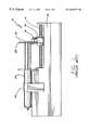
- FIG. 2is a side view of a syringe in accordance with aspects of the invention shown in partial cross section and connected to an infusion administration set, the syringe engaged with a part of a syringe driver embodying further aspects, other parts of the syringe driver not being shown;
- FIG. 3is an end view of the syringe shown in FIG. 2 showing a guide rail slot in the plunger, the half nut, and identification markers in the body flange;
- FIG. 4is a partial cross-section of the syringe shown in FIG. 2 more clearly showing that there exists no bottom arm of the syringe plunger stem so that the plunger and lead screw of the syringe driver may be positioned more closely together;
- FIG. 5is a cross-section view of an alternate embodiment of a syringe plunger showing an H-section configuration of the stem and the position of the lead screw in the stem;
- FIG. 6is a partial cross-section top view of the syringe shown in FIG. 5 showing the markers on the syringe plunger stem usable in indicating near end of infusion and end of infusion, and showing double plunger flanges with guide rail slots formed in both plunger flanges;
- FIG. 7is a perspective view of a half nut formed in the plunger flanges of the syringe shown in FIGS. 2 through 4 and which may also be formed in the syringe of FIGS. 5 and 6;
- FIG. 8is an example of an ambulatory syringe driver system usable with the syringes shown in previous figures, and indicating the placement of the syringe of FIGS. 2 through 4 to be inserted in the syringe driver, the casing for the syringe driver being in an open condition;
- FIGS. 9 and 10demonstrate a mounting arrangement of a syringe in accordance with aspects of the invention where the guide device comprises an arm that engages the slots of the syringe plunger flanges.
- FIG. 9shows a syringe partially inserted into a syringe driver and engaged with the lead screw, the casing of the driver being in an open condition
- FIG. 10shows the syringe fully inserted and ready for use;
- FIGS. 11 and 12show an alternate arrangement for mounting a syringe in accordance with aspects of the invention wherein the lead screw is located at the bottom of the casing and the guide rail is at the top.
- FIG. 11shows the syringe driver casing in an open position while FIG. 12 shows the casing in a closed condition with the syringe secured in position for the infusion of its contents to a patient by operation of the syringe driver;
- FIG. 13presents a block diagram of a layout of a syringe drive system in accordance with aspects of the invention.
- FIG. 2in a generally schematic view there is shown a syringe 30 for use with a syringe driver 66 embodying aspects of the present invention and together forming a syringe driver system 64 .
- the syringe 30includes a syringe body 32 having a side wall 34 which in two embodiments may be cylindrical or elliptical in shape, formed with a nozzle end 36 at its distal tip and an open end 38 at its proximal end terminating in an outwardly directed body flange 40 .
- a fluid administration set 37may be mounted.
- Such setsare well known to those skilled in the art and include tubing, and in some cases, valves, injector ports, and clamps. Other devices may also be included in the administration set.
- the syringe body flange 40is substantially rectangular and the syringe body 32 is positioned to one side of the syringe body flange 40 so that one side of the flange 40 projects farther from the syringe body 32 than at the other side.
- the shape of the syringe body flange 40may deviate from the substantially rectangular shape shown in FIG. 3 .
- FIG. 4presents a view of the syringe 30 without the driver 66 of FIG. 1.
- a plunger 42as shown in FIGS. 2, 4 , and 8 is slidably inserted in the syringe body 32 and has a rubber- or latex-free stopper 44 fitted at one end within the syringe body and a plunger flange 46 at its free end.
- the plunger flange 46 in this embodimentcomprises two co-axial and parallel spaced-apart disks 46 A and 46 B.
- the stem 47 of the plunger 42 shown in FIGS. 2, 4 , and 8only has three stem arms, the lowermost stem arm being omitted so that the lead screw 54 can be accommodated as shown in FIG. 2 .
- FIGS. 5 and 6An alternate embodiment of a plunger is shown in FIGS. 5 and 6 wherein an “H” section plunger stem 57 is used. It has been found that this configuration provides greater and more even rigidity of the plunger 42 .
- the syringe body flange 40includes an opening (not shown) through which the stopper 44 is inserted during assembly of the syringe 30 .
- the openingis marginally smaller than the internal diameter of the syringe barrel and has slots in it corresponding to the stem edges.
- a disc 43 located just behind the rubber stopper 44would be just small enough to fit through the hole with the stem edges engaging with the slots.
- the rubber stopper 44 ahead of the discwould compress to fit through the hole in flange 40 , then expand to form a seal with the internal wall of the barrel of the syringe.
- the disc 46does not enter the syringe barrel, its size is independent of the syringe barrel diameter.
- the slots in the syringe body flange 40engage the edges of the plunger stem so that the plunger 42 is unable to rotate in relation to the syringe body 32 resulting in greater stability of the syringe and avoiding possible misalignment with markers formed in the plunger, as is discussed below.
- the plunger flange 46has two special features. Referring now in particular to FIGS. 3 and 7, first, two aligned and substantially U-shaped cut-outs 48 are provided in the disks 46 A, 46 B and each disk 46 A, 46 B is formed with at least one thread. The embodiment shown in FIGS. 3 and 7 is provided with a half-thread 50 on each disk 46 A, 46 B.
- the threaded cut-outs 48define a threaded portion 50 of the plunger flange 46 .
- the threaded portion 50effectively comprises a recessed half-nut. In alternate embodiments, threads may also be formed between the disks 46 A, 46 B such as by making the plunger flange 46 a solid piece without separate disks 46 A and 46 B.
- the threads 50may extend from one end of the flange to the other.
- the edges of the plunger flange 46 adjacent the threaded portion 50are formed to guide the threaded portion 50 onto the threaded shaft of the lead screw 54 .
- theyare flared outward from a U-shape to form more of a rounded V-shape. This shape facilitates inserting the syringe onto the threaded shaft making syringe loading faster, easier, and more accurate.
- the second feature of the plunger flange 46is a guide slot 52 formed in the circumferential edges of the disks 46 A, 46 B at a position opposite the threaded portion 50 . Since the plunger flange 46 is circular, the guide slot 52 is diametrically opposite the threaded portion 50 . The guide slot is located and shaped to accept a guide rail that keeps the plunger flange against the threaded lead screw shaft. Since the lowermost piece of stem has been omitted from the plunger 42 in one embodiment, and in another embodiment, comprises two parallel stem arms that are spaced apart, the area extending from the threaded portion 50 of the plunger flange 46 to the stopper 44 is clear. This permits placement of the syringe 30 closer to the threaded lead screw shaft 54 resulting in a smaller syringe drive system 64 .
- plunger flange shapesare possible.
- a plunger flange having a rectangular shapemay be used having two guide rail slots formed on the edge opposite the threaded lead screw engaging portion. Two guide rails positioned on either side of the lead screw may add even further stability to the plunger, especially under heavy loads.
- one of the stem arms of the plunger 42in this case the nearmost arm 56 , is provided with a linear grid made up of a series of equally spaced markers 58 along the length of the stem arm.
- the distal markers 58 at the distal end 60which in this embodiment is the end nearer the stopper 44 , are small in comparison to the markers 58 at the proximal end 61 , which in this embodiment is the end nearer the plunger flange 46 .
- these markers 58serve in detecting linear motion of the syringe and provide an indication of the amount of fluid remaining in the syringe.
- identification markers 62which take the form, in this embodiment, of slots.
- these identification markersmay be used to provide an indication of the type, e. g., size, of syringe being used.
- Other types of markersmay be used as well as different numbers of them. For example, in one embodiment, it was found to be more effective to use a set of three slots for identification of the syringe.
- the syringe driver 66has a casing 68 upon which a threaded lead screw shaft 54 is rotatably mounted. Preferably, the thread on the shaft 54 is square cut.
- the shaft 54is journalled at either end on bearings and is driven by means of a motor (not shown) mounted alongside but spaced apart from the threaded shaft 54 .
- the motor and threaded shaft 54are connected by a series of gears, including a drive gear 70 .
- the motormay be powered by batteries (not shown) located in the casing 68 or, in the case of a non-ambulatory syringe driver, by main outlet power.
- the syringe body 32rests on the casing 68 and the flange 46 end of the plunger 42 lies parallel with, but spaced apart from, the threaded shaft 54 with the threaded portion 50 directly engaging the threaded shaft 54 such that the threaded portion is engaged with and can follow the threaded shaft.
- a substantial advantage of the syringe driver system 64 embodying the present inventionis that, because no stem arm is present in the plunger flange 42 in the area extending from the threaded portion 50 of the plunger flange 46 to the stopper 44 , the threaded shaft 54 can be accommodated in that area so as to take up much less space and effectively be within the confines of the size of the syringe when fully extended. This is shown in FIG. 2 although in this figure, the syringe is not fully extended. This is in stark contrast to the arrangement shown in FIG. 1 for the conventional syringe driver where the threaded shaft is located outside the confines of the syringe.
- the casing 68includes an elongate guide rail 72 which extends parallel to the threaded shaft 54 .
- the guide rail 72engages the guide slot 52 formed in the plunger flange 46 (FIG. 3 ).
- the plunger flange 46is securely sandwiched between the guide rail 72 and the threaded shaft 54 and the threaded portion 50 of the plunger flange 46 is securely seated on the threaded shaft 54 such that any rotation of the threaded shaft 54 causes the plunger flange 46 to follow the rotation and drive the plunger 42 into or out of the syringe body 32 as desired.
- use of the guide systemprevents the syringe plunger from rotating.
- a guide railis particularly advantageous when viscous fluids are in the syringe or a high impedance is encountered downstream which oppose movement of the plunger into the syringe body. Such opposition forces can cause the syringe plunger flange to tend to raise up and off the lead screw thus disengaging. Absent the guide rail holding the plunger flange in contact with the lead screw, infusion of the contents of the syringe may not occur.
- the guide rail 72provides a guide for the travel of the plunger flange 46 and also prevents the threaded portion 50 from being lifted up and away from the threaded shaft 54 during rotation of the shaft 54 .
- the guide rail 72provides a guide for the travel of the plunger flange 46 and also prevents the threaded portion 50 from being lifted up and away from the threaded shaft 54 during rotation of the shaft 54 .
- any syringe used in the syringe driver system embodying the present inventionis not going to be subject to wear due to prolonged use since the threaded portion of the plunger is only engaged with the threaded shaft for one use.
- a new threaded shaft engaging portion 50is provided to give an accurate direct mechanical engagement between the plunger 42 and the threaded shaft 54 .
- the casing 68is provided with two opto-electronic detectors in this embodiment.
- the first detector 74is used to provide detection of linear movement of the syringe plunger and a warning when the near-end-of-infusion (NEOI) point is being reached, i. e., when the syringe is almost empty and needs replacement.
- the detector 74is mounted on the casing 68 adjacent the stem arm 56 upon which the markers 58 , 60 (FIG. 6) are formed.
- the detector 74is of substantially horse-shoe shape, one end of the horse shoe housing a light source and the other end of the horse shoe housing a pair of detectors located alongside one another such that light from the light source is blocked by the arm 56 so that neither of the detectors are illuminated but, when a marker 58 is positioned between the light source and the detectors, one of the detectors is illuminated.
- the optoelectronics switch 74As the syringe plunger travels along the shaft 54 , equally spaced dark and light signals are detected by the optoelectronics switch 74 . The timing of these signals can be used by a control system to confirm that the plunger is moving at the correct rate.
- a lack of detection of dark and light signalsindicates to the syringe driver that no movement of the syringe plunger is occurring. This may be the result of an exhausted syringe, which means that the end of infusion (“EOI”) has been reached, thus also providing detection of such condition.
- the processor of the syringe drivermay be programmed to determine the EOI after first detecting the NEOI and to provide an audible and/or visual alarm or other indication of the EOI.
- the larger markersallow the light source of the NEOI detector to illuminate both detectors. This serves as an indication to a control system of the syringe driver that there has been a transition from the smaller markers at the distal end 60 to the larger markers at the proximal end 61 which means that the NEOI point is being approached and the syringe needs to be replaced. Such detection can trigger an alarm, provide a warning light or other form of indication.
- the respective sizes of the markingscan be reversed or the shapes or configurations can be changed to obtain the same effect and/or the transition or approach of the NEOI point can be encoded differently on the arm.
- the second detector 76is a syringe identification detector which again comprises a horse-shoe shaped optoelectronic detector having a light source in one of its ends and at least a pair of detectors in its other end. A plurality of such optoelectronic detectors arranged adjacent one another can be provided instead of just one.
- the optoelectronic detector 76or detectors, so as to provide an indication of the type of syringe inserted in the casing 68 and any other characteristics that the control system of the syringe driver 66 may need to operate in accordance with the specific syringe inserted in the syringe driver.
- the ability of the syringe driver to automatically recognize a characteristic or characteristics of the syringe, for example the volume of a syringe inserted in the driver,means that this information need not be entered manually thus lessening the possibility of human error.
- the casing 68comprises a generally elongate and rectangular housing comprising a base 80 and a cover 82 that is hinged to the base 80 .
- the casing 68is dimensioned to accommodate a fully extended syringe 30 , although the syringe shown in FIG. 8 is only partially extended in accordance with this particular infusion. Inner details of the case, such as the motor, gears, and lead screw, are not shown for purposes of clarity of illustration of the casing.
- the motoris controlled by a control panel 84 on the cover 82 and the settings and operation of the driver can be monitored by a display 86 for indicating pump operating parameters such as the infusion rate.
- the display 86is located on the cover 82 adjacent the control panel.
- a control system(not shown) comprising a control circuit or microprocessor is housed within the casing 68 and connected to the control panel and display.
- the detectors 74 , 76are linked to the control system to provide information about the type of syringe inserted in the casing 68 as well as the progress of the infusion and proximity of the NEOI point.
- the control systemcan be programmed by the control panel 84 to infuse a particular volume of fluid per unit time or to vary the number of infusions of a particular dose required at respective times in accordance with the drug characteristics and any relevant patient information.
- the use of the identification markers 62 and the detector 76 , or detectors,enables the syringe driver embodying the present invention to recognize the volume of the syringe installed. Based on this information, the control system can be calibrated in milliliters per hour rather than millimeters per hour. This is an improvement over conventional ambulatory syringe drivers which calibrate only in millimeters per hour. Thus, medical staff will find syringe drivers embodying the present invention easier to use since medical staff are well-used to dealing in volumes per unit time rather than lengths per unit time.
- FIGS. 9 and 10Two particular embodiments of a casing 68 are now discussed.
- the first embodimentis shown in FIGS. 9 and 10.
- the cover 88is hinged to the base 90 along the central axis of the threaded shaft 54 .
- a spring plate 92extends along the base 90 and is provided with a guide rail 72 .
- the cover 88is opened, the syringe 30 can be inserted in the cover in a cassette-like manner and the threaded portion 50 of the plunger flange 46 engaged with the threaded shaft 54 .
- the plunger body 32rests on another area of the base 90 of the casing.
- the cover 88can then be closed as shown in FIG. 10 .
- the spring plate 92is pushed away from the threaded shaft 54 until the cover is fully closed at which point the guide rail 72 on the spring plate 92 is sprung into position into the guide slot 52 in the plunger flange 46 .
- the spring plate 92is locked in place by the complete closure of the cover 88 .
- the spring plate 92extends upward and the cover 88 includes a channel. Upon closure of the cover 88 the top of the spring plate 92 engages the channel. In either embodiment, if the syringe 30 is inserted incorrectly the cover 88 cannot be closed.
- the internal surface contours of the base 90correspond closely to the shape of the outer periphery of the syringe body flange 40 thus securing the syringe body 32 within the casing 68 and preventing any turning or re-alignment of the syringe body with respect to the casing.
- a pair of guide ribsare molded into the cover 88 to receive a longitudinal edge of the syringe body flange 40 and prevent movement of the syringe body 32 longitudinally with respect to the casing 68 .
- the cover 94is not hinged about the threaded shaft 54 .
- the guide rail 72is provided on the lid of the cover 94 .
- the syringe 30is inserted in the cover 94 and there is enough play when inserting the syringe 30 in the cover 94 for the edge of the plunger flange 46 to slide over the guide rail 72 until the guide rail 72 is engaged in the guide slot 52 .
- the threaded portion 50is downwardly depending and pointing substantially towards the threaded shaft 54 .
- the cover 94is hinged on the far side of the casing 68 to bring the threaded portion 50 into direct engagement with the threaded shaft 54 at which point the cover 94 is closed on the base portion 96 as shown in FIG. 12 .
- the action of loading and closing the casing 68in both the embodiments shown in FIGS. 9 to 12 , locates the threaded portion 50 of the plunger flange 46 into direct engagement with the threaded shaft 54 .
- the successful closing of the casing 68is preferably monitored by an optical switch, microswitch or the like which disables the motor and/or any control devices so as to prevent the syringe driver from working without a syringe being properly loaded.
- different volumes of syringesall have common exterior characteristics allowing all volumes of syringes to be correctly loaded in the same syringe driver.
- the volume of the syringecan then be determined by using the coded identification markers 62 which are molded into the syringe body flange 40 of the syringe body 32 .
- the syringe disclosed in the above embodimentshas been provided with additional features, the syringe can still function as a normal syringe for use without the syringe driver.
- the syringes for use with the syringe driverare sold as dedicated units for loading in the syringe driver and may come in the form of pre-filled syringes.
- the syringes 30 used with the syringe driver embodying the present inventionhave a higher width to length ratio than normal syringes so that the length of the syringe is minimized for a given volume of syringe. It is envisaged that the use of non-cylindrical syringe bodies could be advantageous as a means of registering the syringe body 32 in the casing 68 or to provide a more convenient case shape to the user.
- a syringe driver using the same conceptscan be provided for driving multiple syringes.
- the above-mentioned examples of the plungerinvolve the use of a threaded portion 50 on the plunger flange 46 for engaging the threaded lead screw shaft 54 .
- the inventioncan still be implemented by engaging an unmodified edge of a plunger flange 46 directly with the threaded shaft 54 , the edge of the plunger flange sitting between the threads of the threaded shaft 54 . It is envisaged that the arrangement of the guide slot 52 and guide rail 72 can be reversed or otherwise implemented.
- the guide rail 72can be replaced with an elongate channel running substantially parallel to the threaded shaft 54 and the guide slot 52 replaced by a projection extending from the plunger for reception in the channel.
- an elongate plunger stem armmay be formed on the plunger at a position substantially opposite the position at which the plunger is engaged with the threaded shaft and a guiding system comprising the arm and a bifurcated element are located on the casing 68 to straddle the arm.
- the syringe drivercan also be provided with means to sense that a syringe has been removed from the casing or the casing is empty.
- Such sensing meanscan comprise an optical detector, microswitch or the like.
- the sensing meanscan provide a signal to a stop valve or the like to close the fluid line to a patient to prevent syphoning of the medicament in the line when the syringe has been removed from the casing or if the casing is empty.
- FIG. 13a schematic, block diagram of an example of a compact syringe drive system incorporating aspects of the invention is presented. Additionally, the compact syringe drive system of FIG. 13 includes aspects of FIGS. 9 and 10.
- the syringe body 32is located adjacent the battery 100 .
- the motor 102is connected to a gear drive 70 which drives the lead screw 54 .
- the internal components of the gear drive 70are not shown in the interest of retaining clarity in the drawing.
- a motor encoder disk 104 for use in detecting the speed and direction of the motoris provided.
- An optical switch(not shown) is mounted so as to read the encoder disk 104 .
- a partial view of a bearing block 103 supporting one end of the lead screw 54is shown. This arrangement results in a compact syringe drive system.
- a potentiometer functioning as the detectorcould be located in the pump case in a position such that the spur of the plunger flange 46 would contact the potentiometer during its entire range of travel. The output of the potentiometer could then be used to monitor the position of the plunger flange 46 and thus the plunger so that the near-end-of-infusion point could be determined.
- the syringe driver of the present inventionhas fewer parts in that a driver block is not used with the resulting decrease in expense and increase in manufacturing ease. Additionally, the system is more compact and the need for maintenance should be lowered because of this lack of a driver block which is prone to wear.
Landscapes
- Health & Medical Sciences (AREA)
- Vascular Medicine (AREA)
- Engineering & Computer Science (AREA)
- Anesthesiology (AREA)
- Biomedical Technology (AREA)
- Heart & Thoracic Surgery (AREA)
- Hematology (AREA)
- Life Sciences & Earth Sciences (AREA)
- Animal Behavior & Ethology (AREA)
- General Health & Medical Sciences (AREA)
- Public Health (AREA)
- Veterinary Medicine (AREA)
- Infusion, Injection, And Reservoir Apparatuses (AREA)
Abstract
Description
Claims (29)
Priority Applications (22)
| Application Number | Priority Date | Filing Date | Title |
|---|---|---|---|
| US09/247,756US6645177B1 (en) | 1999-02-09 | 1999-02-09 | Directly engaged syringe driver system |
| NZ538619ANZ538619A (en) | 1999-02-09 | 2000-02-08 | Plunger for a directly engaged syringe driver system |
| ES04014401TES2361351T3 (en) | 1999-02-09 | 2000-02-08 | MECHANICAL INJECTION SYSTEM. |
| NZ538618ANZ538618A (en) | 1999-02-09 | 2000-02-08 | Directly engaged syringe driver system |
| EP00914551AEP1156843B1 (en) | 1999-02-09 | 2000-02-08 | Directly engaged syringe driver system |
| AT00914551TATE275990T1 (en) | 1999-02-09 | 2000-02-08 | DIRECTLY CONNECTED DRIVE DEVICE FOR A SYRINGE |
| PT04014401TPT1457220E (en) | 1999-02-09 | 2000-02-08 | Medical infusion system |
| CA002614656ACA2614656C (en) | 1999-02-09 | 2000-02-08 | Directly engaged syringe driver system |
| CA002360139ACA2360139C (en) | 1999-02-09 | 2000-02-08 | Directly engaged syringe driver system |
| DE60045046TDE60045046D1 (en) | 1999-02-09 | 2000-02-08 | Medical infusion system |
| AU35926/00AAU772647B2 (en) | 1999-02-09 | 2000-02-08 | Directly engaged syringe driver system |
| DE60013782TDE60013782T2 (en) | 1999-02-09 | 2000-02-08 | DIRECTLY CONNECTED DRIVE DEVICE OF A SYRINGE |
| AT04014401TATE482733T1 (en) | 1999-02-09 | 2000-02-08 | MEDICAL INFUSION SYSTEM |
| DK04014401.6TDK1457220T3 (en) | 1999-02-09 | 2000-02-08 | Medical infusion system |
| NZ513389ANZ513389A (en) | 1999-02-09 | 2000-02-08 | Directly engaged syringe driver system |
| PCT/US2000/003270WO2000047254A1 (en) | 1999-02-09 | 2000-02-08 | Directly engaged syringe driver system |
| EP04014401AEP1457220B1 (en) | 1999-02-09 | 2000-02-08 | Medical Infusion System |
| US10/657,930US7338472B2 (en) | 1999-02-09 | 2003-09-09 | Directly engaged syringe driver system |
| NZ529534ANZ529534A (en) | 1999-02-09 | 2003-11-14 | Directly engaged syringe driver system |
| AU2004205142AAU2004205142B2 (en) | 1999-02-09 | 2004-08-19 | Directly engaged syringe driver system |
| US12/042,275US7972306B2 (en) | 1999-02-09 | 2008-03-04 | Directly engaged syringe driver system |
| CY20101101200TCY1111562T1 (en) | 1999-02-09 | 2010-12-29 | MEDICAL INJECTION SYSTEM |
Applications Claiming Priority (1)
| Application Number | Priority Date | Filing Date | Title |
|---|---|---|---|
| US09/247,756US6645177B1 (en) | 1999-02-09 | 1999-02-09 | Directly engaged syringe driver system |
Related Child Applications (1)
| Application Number | Title | Priority Date | Filing Date |
|---|---|---|---|
| US10/657,930DivisionUS7338472B2 (en) | 1999-02-09 | 2003-09-09 | Directly engaged syringe driver system |
Publications (1)
| Publication Number | Publication Date |
|---|---|
| US6645177B1true US6645177B1 (en) | 2003-11-11 |
Family
ID=22936241
Family Applications (3)
| Application Number | Title | Priority Date | Filing Date |
|---|---|---|---|
| US09/247,756Expired - LifetimeUS6645177B1 (en) | 1999-02-09 | 1999-02-09 | Directly engaged syringe driver system |
| US10/657,930Expired - LifetimeUS7338472B2 (en) | 1999-02-09 | 2003-09-09 | Directly engaged syringe driver system |
| US12/042,275Expired - Fee RelatedUS7972306B2 (en) | 1999-02-09 | 2008-03-04 | Directly engaged syringe driver system |
Family Applications After (2)
| Application Number | Title | Priority Date | Filing Date |
|---|---|---|---|
| US10/657,930Expired - LifetimeUS7338472B2 (en) | 1999-02-09 | 2003-09-09 | Directly engaged syringe driver system |
| US12/042,275Expired - Fee RelatedUS7972306B2 (en) | 1999-02-09 | 2008-03-04 | Directly engaged syringe driver system |
Country Status (12)
| Country | Link |
|---|---|
| US (3) | US6645177B1 (en) |
| EP (2) | EP1457220B1 (en) |
| AT (2) | ATE275990T1 (en) |
| AU (2) | AU772647B2 (en) |
| CA (2) | CA2614656C (en) |
| CY (1) | CY1111562T1 (en) |
| DE (2) | DE60013782T2 (en) |
| DK (1) | DK1457220T3 (en) |
| ES (1) | ES2361351T3 (en) |
| NZ (4) | NZ538618A (en) |
| PT (1) | PT1457220E (en) |
| WO (1) | WO2000047254A1 (en) |
Cited By (76)
| Publication number | Priority date | Publication date | Assignee | Title |
|---|---|---|---|---|
| US20020173769A1 (en)* | 2001-05-18 | 2002-11-21 | Gray Larry B. | Infusion set for a fluid pump |
| US20030130618A1 (en)* | 2002-01-04 | 2003-07-10 | Gray Larry B. | Loading mechanism for infusion pump |
| US20040135078A1 (en)* | 2002-07-24 | 2004-07-15 | Deka Products Limited Partnership | Optical displacement sensor for infusion devices |
| US20040220526A1 (en)* | 2003-04-29 | 2004-11-04 | Boyne-Aitken David E. | Syringe pump bearing mechanism |
| US20060079833A1 (en)* | 2002-11-11 | 2006-04-13 | Susumu Kobayashi | Syringe pump |
| US20060173439A1 (en)* | 2005-01-18 | 2006-08-03 | Thorne Gale H Jr | Syringe drive system |
| US20070080223A1 (en)* | 2005-10-07 | 2007-04-12 | Sherwood Services Ag | Remote monitoring of medical device |
| US20070142777A1 (en)* | 2005-11-29 | 2007-06-21 | Klein Medical Limited | Optical reader for syringe |
| US20080161753A1 (en)* | 2002-06-14 | 2008-07-03 | Baxter International Inc. | Infusion pump |
| US20090005730A1 (en)* | 2002-01-22 | 2009-01-01 | Hans-Josef Gerlach | Syringe pump having a piston brake |
| US20090292246A1 (en)* | 2008-05-20 | 2009-11-26 | Slate John B | Cassette for a hidden injection needle |
| US20100022955A1 (en)* | 2008-07-23 | 2010-01-28 | Slate John B | System and method for an injection using a syringe needle |
| US7704231B2 (en) | 2004-02-18 | 2010-04-27 | Ares Trading S.A. | Hand-held electronically controlled injection device for injecting liquid medications |
| AU2008200838B2 (en)* | 2002-06-14 | 2010-06-10 | Baxter International Inc. | Infusion pump |
| US20100174162A1 (en)* | 2002-11-25 | 2010-07-08 | Boston Scientific Scimed, Inc. | Injection device |
| US20110015610A1 (en)* | 2009-07-15 | 2011-01-20 | Fresenius Medical Care Holdings, Inc. | Medical fluid cassettes and related systems and methods |
| US7935074B2 (en) | 2005-02-28 | 2011-05-03 | Fresenius Medical Care Holdings, Inc. | Cassette system for peritoneal dialysis machine |
| US8016789B2 (en) | 2008-10-10 | 2011-09-13 | Deka Products Limited Partnership | Pump assembly with a removable cover assembly |
| US8034026B2 (en) | 2001-05-18 | 2011-10-11 | Deka Products Limited Partnership | Infusion pump assembly |
| US8066672B2 (en) | 2008-10-10 | 2011-11-29 | Deka Products Limited Partnership | Infusion pump assembly with a backup power supply |
| US8142653B2 (en) | 2002-06-04 | 2012-03-27 | Fresenius Medical Care Deutschland Gmbh | Medical fluid cassettes and related systems |
| US8192401B2 (en) | 2009-03-20 | 2012-06-05 | Fresenius Medical Care Holdings, Inc. | Medical fluid pump systems and related components and methods |
| US8223028B2 (en) | 2008-10-10 | 2012-07-17 | Deka Products Limited Partnership | Occlusion detection system and method |
| US8262616B2 (en) | 2008-10-10 | 2012-09-11 | Deka Products Limited Partnership | Infusion pump assembly |
| US20120230844A1 (en)* | 2011-03-09 | 2012-09-13 | Fresenius Medical Care Holdings, Inc. | Medical fluid delivery sets and related systems and methods |
| US8267892B2 (en) | 2008-10-10 | 2012-09-18 | Deka Products Limited Partnership | Multi-language / multi-processor infusion pump assembly |
| US8692167B2 (en) | 2010-12-09 | 2014-04-08 | Fresenius Medical Care Deutschland Gmbh | Medical device heaters and methods |
| US8708376B2 (en) | 2008-10-10 | 2014-04-29 | Deka Products Limited Partnership | Medium connector |
| US8720913B2 (en) | 2009-08-11 | 2014-05-13 | Fresenius Medical Care Holdings, Inc. | Portable peritoneal dialysis carts and related systems |
| US20140188076A1 (en)* | 2011-12-21 | 2014-07-03 | Deka Products Limited Partnership | Syringe Pump, and Related Method and System |
| US8932032B2 (en) | 2005-07-13 | 2015-01-13 | Fresenius Medical Care Holdings, Inc. | Diaphragm pump and pumping systems |
| US20150209505A1 (en)* | 2012-08-29 | 2015-07-30 | Unitract Syringe Pty Ltd | Controlled delivery drive mechanisms for drug delivery pumps |
| CN104968380A (en)* | 2013-01-29 | 2015-10-07 | 赛诺菲-安万特德国有限公司 | Assemblies for detecting plunger position |
| US9180240B2 (en) | 2011-04-21 | 2015-11-10 | Fresenius Medical Care Holdings, Inc. | Medical fluid pumping systems and related devices and methods |
| US9180245B2 (en) | 2008-10-10 | 2015-11-10 | Deka Products Limited Partnership | System and method for administering an infusible fluid |
| US9186449B2 (en) | 2011-11-01 | 2015-11-17 | Fresenius Medical Care Holdings, Inc. | Dialysis machine support assemblies and related systems and methods |
| US20150379900A1 (en)* | 2014-04-17 | 2015-12-31 | University Of Pittsburgh-Of The Commonwealth System Of Higher Education | Modular, wireless, drug simulant injection sensor system and methods of employing |
| US20160082181A1 (en)* | 2001-05-18 | 2016-03-24 | Deka Products Limited Partnership | Infusion Pump Assembly |
| US9295778B2 (en)* | 2011-12-21 | 2016-03-29 | Deka Products Limited Partnership | Syringe pump |
| US9500188B2 (en) | 2012-06-11 | 2016-11-22 | Fresenius Medical Care Holdings, Inc. | Medical fluid cassettes and related systems and methods |
| US9561323B2 (en) | 2013-03-14 | 2017-02-07 | Fresenius Medical Care Holdings, Inc. | Medical fluid cassette leak detection methods and devices |
| US9610392B2 (en) | 2012-06-08 | 2017-04-04 | Fresenius Medical Care Holdings, Inc. | Medical fluid cassettes and related systems and methods |
| US9694125B2 (en) | 2010-12-20 | 2017-07-04 | Fresenius Medical Care Holdings, Inc. | Medical fluid cassettes and related systems and methods |
| US9744300B2 (en) | 2011-12-21 | 2017-08-29 | Deka Products Limited Partnership | Syringe pump and related method |
| US20170281868A1 (en)* | 2014-09-05 | 2017-10-05 | Vetter Pharma-Fertigung GmbH & Co. KG | Pen-type injector |
| US9974904B2 (en) | 2008-05-20 | 2018-05-22 | Avant Medical Corp. | Autoinjector system |
| USD829890S1 (en) | 2012-04-20 | 2018-10-02 | Amgen Inc. | Injection device |
| US10092706B2 (en) | 2011-04-20 | 2018-10-09 | Amgen Inc. | Autoinjector apparatus |
| US10092703B2 (en) | 2013-03-15 | 2018-10-09 | Amgen Inc. | Drug cassette, autoinjector, and autoinjector system |
| US10117985B2 (en) | 2013-08-21 | 2018-11-06 | Fresenius Medical Care Holdings, Inc. | Determining a volume of medical fluid pumped into or out of a medical fluid cassette |
| US20180318495A1 (en)* | 2012-08-28 | 2018-11-08 | Osprey Medical, Inc. | Medium injection diversion and measurement |
| US10322231B2 (en) | 2011-09-02 | 2019-06-18 | UNL Holdings | Drive mechanism for drug delivery pumps with integrated status indication |
| US10391241B2 (en) | 2010-01-22 | 2019-08-27 | Deka Products Limited Partnership | Syringe pump having a pressure sensor assembly |
| US10405757B2 (en) | 2014-02-25 | 2019-09-10 | Icu Medical, Inc. | Patient monitoring system with gatekeeper signal |
| US10492990B2 (en) | 2013-03-15 | 2019-12-03 | Amgen Inc. | Drug cassette, autoinjector, and autoinjector system |
| US10549029B2 (en) | 2011-09-02 | 2020-02-04 | Unl Holdings Llc | Drive mechanism for drug delivery pumps with integrated status indication |
| US10695487B2 (en) | 2016-08-30 | 2020-06-30 | Unl Holdings Llc | Controlled delivery drive mechanisms for drug delivery pumps |
| US10722645B2 (en) | 2011-12-21 | 2020-07-28 | Deka Products Limited Partnership | Syringe pump, and related method and system |
| US10744268B2 (en) | 2014-12-04 | 2020-08-18 | Tolmar Therapeutics, Inc. | Syringe plunger system with self-locking threaded geometry |
| USD898908S1 (en) | 2012-04-20 | 2020-10-13 | Amgen Inc. | Pharmaceutical product cassette for an injection device |
| US10918788B2 (en) | 2011-09-02 | 2021-02-16 | Unl Holdings Llc | Drive mechanism for drug delivery pumps with integrated status indication |
| US10967119B1 (en)* | 2019-04-01 | 2021-04-06 | Azizi Bilal | Wearable medication injecting device |
| WO2021113739A1 (en) | 2019-12-05 | 2021-06-10 | Thomas Ballet | Formulations of anti-cd38 antibodies for subcutaneous administration |
| US20210269776A1 (en)* | 2018-06-28 | 2021-09-02 | Cedars-Sinai Medical Center | Compact mechanical syringe extruder for 3d bioprinting of cell laden gels |
| US11135375B2 (en) | 2012-08-28 | 2021-10-05 | Osprey Medical, Inc. | Volume monitoring systems |
| US11173244B2 (en) | 2011-09-02 | 2021-11-16 | Unl Holdings Llc | Drive mechanism for drug delivery pumps with integrated status indication |
| US11217340B2 (en) | 2011-12-21 | 2022-01-04 | Deka Products Limited Partnership | Syringe pump having a pressure sensor assembly |
| US11270792B2 (en) | 2015-10-19 | 2022-03-08 | Icu Medical, Inc. | Hemodynamic monitoring system with detachable display unit |
| US11499841B2 (en) | 2019-04-12 | 2022-11-15 | Osprey Medical, Inc. | Energy-efficient position determining with multiple sensors |
| US11655302B2 (en) | 2019-06-10 | 2023-05-23 | Sanofi | Anti-CD38 antibodies and formulations |
| WO2024002410A1 (en)* | 2022-07-01 | 2024-01-04 | Lenus Infusionstechnik Gmbh & Co.Kg | Dosing system |
| US12098738B2 (en) | 2011-12-21 | 2024-09-24 | Deka Products Limited Partnership | System, method, and apparatus for clamping |
| US12131826B2 (en) | 2011-12-21 | 2024-10-29 | Deka Products Limited Partnership | Syringe pump and related method |
| US12186531B2 (en) | 2008-10-10 | 2025-01-07 | Deka Products Limited Partnership | Infusion pump assembly |
| EP4585228A2 (en) | 2017-04-07 | 2025-07-16 | Apellis Pharmaceuticals, Inc. | Dosing regimens and related compositions and methods |
| US12370327B2 (en) | 2008-10-10 | 2025-07-29 | Deka Products Limited Partnership | Infusion pump methods, systems and apparatus |
Families Citing this family (70)
| Publication number | Priority date | Publication date | Assignee | Title |
|---|---|---|---|---|
| IL156245A0 (en)* | 2000-12-22 | 2004-01-04 | Dca Design Int Ltd | Drive mechanism for an injection device |
| WO2003006090A1 (en)* | 2001-07-10 | 2003-01-23 | Janet Murphy | Syringe pump mechanism |
| DE20209581U1 (en)* | 2002-06-20 | 2003-10-30 | Braun Melsungen Ag | syringe pump |
| DE10233622A1 (en)† | 2002-07-24 | 2004-02-12 | Disetronic Licensing Ag | Infusion pump, method, control program and semiconductor component for the metered administration of a medical liquid |
| USD1031029S1 (en) | 2003-11-25 | 2024-06-11 | Bayer Healthcare Llc | Syringe plunger |
| US7666169B2 (en) | 2003-11-25 | 2010-02-23 | Medrad, Inc. | Syringe and syringe plungers for use with medical injectors |
| US8057434B2 (en) | 2004-03-31 | 2011-11-15 | Eli Lilly And Company | Injection apparatus having a needle cassette for delivering a pharmaceutical liquid |
| US7291142B2 (en)* | 2004-05-10 | 2007-11-06 | Boston Scientific Scimed, Inc. | Low temperature lesion formation apparatus, systems and methods |
| DE102004042581B4 (en)* | 2004-09-02 | 2022-09-15 | Ypsomed Ag | Auto-Pen for dual-chamber ampoule |
| US7507221B2 (en)* | 2004-10-13 | 2009-03-24 | Mallinckrodt Inc. | Powerhead of a power injection system |
| DE102004063650B4 (en)* | 2004-12-31 | 2022-10-20 | Ypsomed Ag | Lifetime indicator for a product metering device |
| US8512288B2 (en)* | 2006-08-23 | 2013-08-20 | Medtronic Minimed, Inc. | Infusion medium delivery device and method with drive device for driving plunger in reservoir |
| US7905868B2 (en)* | 2006-08-23 | 2011-03-15 | Medtronic Minimed, Inc. | Infusion medium delivery device and method with drive device for driving plunger in reservoir |
| US8926569B2 (en) | 2006-03-15 | 2015-01-06 | Bayer Medical Care Inc. | Plunger covers and plungers for use in syringes and methods of fabricating plunger covers and plungers for use in syringes |
| USD942005S1 (en) | 2007-03-14 | 2022-01-25 | Bayer Healthcare Llc | Orange syringe plunger cover |
| USD847985S1 (en) | 2007-03-14 | 2019-05-07 | Bayer Healthcare Llc | Syringe plunger cover |
| JP5102350B2 (en) | 2007-04-30 | 2012-12-19 | メドトロニック ミニメド インコーポレイテッド | Reservoir filling / bubble management / infusion medium delivery system and method using the system |
| US7963954B2 (en) | 2007-04-30 | 2011-06-21 | Medtronic Minimed, Inc. | Automated filling systems and methods |
| DE102007045189A1 (en)* | 2007-09-21 | 2009-04-09 | Iprm Intellectual Property Rights Management Ag | Position detecting device and method for detecting at least two positions |
| US9345836B2 (en) | 2007-10-02 | 2016-05-24 | Medimop Medical Projects Ltd. | Disengagement resistant telescoping assembly and unidirectional method of assembly for such |
| US9656019B2 (en) | 2007-10-02 | 2017-05-23 | Medimop Medical Projects Ltd. | Apparatuses for securing components of a drug delivery system during transport and methods of using same |
| US10420880B2 (en) | 2007-10-02 | 2019-09-24 | West Pharma. Services IL, Ltd. | Key for securing components of a drug delivery system during assembly and/or transport and methods of using same |
| BRPI0817907B8 (en) | 2007-10-02 | 2021-06-22 | Lamodel Ltd | apparatus for administering a substance to an individual |
| US7967795B1 (en)* | 2010-01-19 | 2011-06-28 | Lamodel Ltd. | Cartridge interface assembly with driving plunger |
| EP2257323B1 (en) | 2008-01-30 | 2019-05-29 | Becton Dickinson France | Dose dividing delivery device |
| US8858501B2 (en) | 2008-04-11 | 2014-10-14 | Medtronic Minimed, Inc. | Reservoir barrier layer systems and methods |
| US9295776B2 (en) | 2008-04-11 | 2016-03-29 | Medtronic Minimed, Inc. | Reservoir plunger head systems and methods |
| US8900190B2 (en) | 2009-09-02 | 2014-12-02 | Medtronic Minimed, Inc. | Insertion device systems and methods |
| US8932256B2 (en) | 2009-09-02 | 2015-01-13 | Medtronic Minimed, Inc. | Insertion device systems and methods |
| US8998840B2 (en) | 2009-12-30 | 2015-04-07 | Medtronic Minimed, Inc. | Connection and alignment systems and methods |
| US9039653B2 (en)* | 2009-12-29 | 2015-05-26 | Medtronic Minimed, Inc. | Retention systems and methods |
| US8858500B2 (en) | 2009-12-30 | 2014-10-14 | Medtronic Minimed, Inc. | Engagement and sensing systems and methods |
| US8998858B2 (en) | 2009-12-29 | 2015-04-07 | Medtronic Minimed, Inc. | Alignment and connection systems and methods |
| US8435209B2 (en) | 2009-12-30 | 2013-05-07 | Medtronic Minimed, Inc. | Connection and alignment detection systems and methods |
| US9421321B2 (en) | 2009-12-30 | 2016-08-23 | Medtronic Minimed, Inc. | Connection and alignment systems and methods |
| US11497850B2 (en) | 2009-12-30 | 2022-11-15 | Medtronic Minimed, Inc. | Connection and alignment detection systems and methods |
| US20120215163A1 (en) | 2009-12-30 | 2012-08-23 | Medtronic Minimed, Inc. | Sensing systems and methods |
| ES2804511T3 (en)* | 2011-09-05 | 2021-02-08 | Hoffmann La Roche | Manual injection device and disposable module |
| CN103127579B (en)* | 2011-11-21 | 2017-06-16 | 上海泽生科技开发股份有限公司 | The drive system of portable injection pump |
| US9174003B2 (en) | 2012-09-28 | 2015-11-03 | Bayer Medical Care Inc. | Quick release plunger |
| US20160114109A1 (en)* | 2013-05-20 | 2016-04-28 | Ross A.M.S. - Advanced Medication Solutions Ltd. | System and method for preparing and delivering a medicament |
| AU2015231396B2 (en) | 2014-03-19 | 2018-12-06 | Bayer Healthcare Llc | System for syringe engagement to an injector |
| ES2551810B1 (en)* | 2014-05-21 | 2016-05-17 | Kiro Robotics Sl | ROBOTIZED SYRINGE ACTUATOR |
| WO2015195533A1 (en)* | 2014-06-16 | 2015-12-23 | Bayer Medical Care Inc. | Syringe identification using photochromic ink |
| US10293102B2 (en) | 2014-12-01 | 2019-05-21 | Carefusion 2200, Inc. | Pump cassettes with piston and infusion pump systems |
| US10245373B2 (en) | 2014-12-01 | 2019-04-02 | Carefusion 2200, Inc. | Pump cassettes with positioning feature and infusion pump systems |
| US10363360B2 (en) | 2014-12-01 | 2019-07-30 | Carefusion 2200, Inc. | Pump cassettes with slider and infusion pump systems |
| US10376639B2 (en) | 2014-12-01 | 2019-08-13 | Carefusion 2200, Inc. | Valving system for infusion cassette |
| US10149943B2 (en) | 2015-05-29 | 2018-12-11 | West Pharma. Services IL, Ltd. | Linear rotation stabilizer for a telescoping syringe stopper driverdriving assembly |
| US10576207B2 (en) | 2015-10-09 | 2020-03-03 | West Pharma. Services IL, Ltd. | Angled syringe patch injector |
| US9987432B2 (en) | 2015-09-22 | 2018-06-05 | West Pharma. Services IL, Ltd. | Rotation resistant friction adapter for plunger driver of drug delivery device |
| US11318254B2 (en) | 2015-10-09 | 2022-05-03 | West Pharma. Services IL, Ltd. | Injector needle cap remover |
| US9480797B1 (en) | 2015-10-28 | 2016-11-01 | Bayer Healthcare Llc | System and method for syringe plunger engagement with an injector |
| JP6885960B2 (en) | 2016-01-21 | 2021-06-16 | ウェスト ファーマ サービシーズ イスラエル リミテッド | Drug delivery device with visual indicators |
| US10646643B2 (en) | 2016-01-21 | 2020-05-12 | West Pharma. Services IL, Ltd. | Needle insertion and retraction mechanism |
| EP3711793B1 (en) | 2016-01-21 | 2021-12-01 | West Pharma Services IL, Ltd. | A method of connecting a cartridge to an automatic injector |
| US11389597B2 (en) | 2016-03-16 | 2022-07-19 | West Pharma. Services IL, Ltd. | Staged telescopic screw assembly having different visual indicators |
| CN105943382B (en)* | 2016-05-18 | 2018-12-07 | 张巍 | A kind of sterile dispensing system |
| US11338090B2 (en) | 2016-08-01 | 2022-05-24 | West Pharma. Services IL, Ltd. | Anti-rotation cartridge pin |
| JP7059251B2 (en) | 2016-08-01 | 2022-04-25 | ウェスト ファーマ サービシーズ イスラエル リミテッド | A spring that prevents the door from closing halfway |
| HUE063479T2 (en) | 2017-01-06 | 2024-01-28 | Bayer Healthcare Llc | Syringe plunger with dynamic seal |
| JPWO2018180758A1 (en)* | 2017-03-30 | 2020-02-06 | テルモ株式会社 | Barrel assembly, method of using syringe, drug solution administration device, and method of assembling the same |
| EP3630226A1 (en) | 2017-05-30 | 2020-04-08 | West Pharma. Services Il, Ltd. | Modular drive train for wearable injector |
| HUE061426T2 (en) | 2018-02-27 | 2023-06-28 | Bayer Healthcare Llc | Syringe piston switch mechanism |
| EP3790461B1 (en)* | 2018-05-10 | 2025-06-25 | University of Pittsburgh - Of the Commonwealth System of Higher Education | Sensing cannula systems |
| BR112022023788A2 (en) | 2020-06-18 | 2022-12-27 | Bayer Healthcare Llc | SYSTEM AND METHOD OF COUPLING A SYRINGE PLUNGER WITH AN INJECTOR |
| DE102020121665A1 (en) | 2020-08-18 | 2022-02-24 | Lenus Infusionstechnik Gmbh & Co Kg | Dosing system with a syringe and a syringe pump |
| US11964127B2 (en)* | 2021-10-13 | 2024-04-23 | Atlanta Biomedical Corporation | External driving mechanism |
| FR3129290B1 (en) | 2021-11-24 | 2023-12-29 | Collin | Syringe holder device, injection device and robotic surgical intervention facility |
| DE102024103900A1 (en)* | 2024-02-12 | 2025-08-14 | GEOMAR Helmholtz-Zentrum für Ozeanforschung Kiel, Stiftung des öffentlichen Rechts | COMBINED SYRINGE-PLUNGER DEVICE AND USE |
Citations (12)
| Publication number | Priority date | Publication date | Assignee | Title |
|---|---|---|---|---|
| US3880138A (en)* | 1973-03-12 | 1975-04-29 | Lear Siegler Inc | Method for injecting contrast media into the vascular system |
| US4508532A (en)* | 1983-09-09 | 1985-04-02 | Ninetronix, Inc. | Ophthalmic aspirator/irrigator and cystotome |
| US4648872A (en) | 1983-11-15 | 1987-03-10 | Kamen Dean L | Volumetric pump with replaceable reservoir assembly |
| US4767406A (en)* | 1985-10-11 | 1988-08-30 | Vickers Plc. | Syringe pumps |
| WO1989011310A1 (en) | 1988-05-16 | 1989-11-30 | Spinello Ronald P | Aspirating hypodermic syringe apparatus and method |
| US4978335A (en) | 1989-09-29 | 1990-12-18 | Medex, Inc. | Infusion pump with bar code input to computer |
| US5236416A (en) | 1991-05-23 | 1993-08-17 | Ivac Corporation | Syringe plunger position detection and alarm generation |
| EP0566825A1 (en) | 1992-04-22 | 1993-10-27 | B. Braun Melsungen AG | Pressure infusion apparatus |
| EP0654279A2 (en) | 1993-11-24 | 1995-05-24 | Liebel-Flarsheim Company | Controlling plunger drives for fluid injections in animals |
| US5545140A (en) | 1991-05-23 | 1996-08-13 | Ivac Corporation | Syringe plunger driver |
| WO1999027981A1 (en) | 1997-12-04 | 1999-06-10 | Bracco Research S.A. | Automatic liquid injection system and method |
| US5954697A (en) | 1998-03-02 | 1999-09-21 | Srisathapat; Chad | Threaded nut syringe plunger for use with a medication infusion pump |
Family Cites Families (16)
| Publication number | Priority date | Publication date | Assignee | Title |
|---|---|---|---|---|
| US2602446A (en)* | 1950-02-27 | 1952-07-08 | Antonina S Glass | Automatic medical injection apparatus |
| US2702547A (en)* | 1950-02-27 | 1955-02-22 | Antonina S Glass | Motor-driven medical injection apparatus and cartridges therefor |
| US3623474A (en)* | 1966-07-25 | 1971-11-30 | Medrad Inc | Angiographic injection equipment |
| US3812843A (en)* | 1973-03-12 | 1974-05-28 | Lear Siegler Inc | Method and apparatus for injecting contrast media into the vascular system |
| US3880038A (en)* | 1973-05-25 | 1975-04-29 | James Mangos | Sandwich die set |
| US4196730A (en)* | 1977-08-01 | 1980-04-08 | Wilson Dennis R | Liquid drug dispenser |
| US4424720A (en)* | 1980-12-15 | 1984-01-10 | Ivac Corporation | Mechanism for screw drive and syringe plunger engagement/disengagement |
| US4908017A (en)* | 1985-05-14 | 1990-03-13 | Ivion Corporation | Failsafe apparatus and method for effecting syringe drive |
| US5127908A (en)* | 1990-06-15 | 1992-07-07 | Sherwood Medical Company | Peristaltic infusion device |
| US5219099A (en)* | 1991-09-06 | 1993-06-15 | California Institute Of Technology | Coaxial lead screw drive syringe pump |
| JP3660678B2 (en)* | 1992-10-15 | 2005-06-15 | ザ ゼネラル ホスピタル コーポレーション | Infusion pump with electronically loadable drug library |
| SE510420C2 (en)* | 1994-11-14 | 1999-05-25 | Cma Microdialysis Ab | Infusion and microdialysis pump |
| US5647853A (en)* | 1995-03-03 | 1997-07-15 | Minimed Inc. | Rapid response occlusion detector for a medication infusion pump |
| AU4534197A (en) | 1996-11-22 | 1998-05-28 | Presnash Pty. Limited | Syringe identification system |
| US6423035B1 (en)* | 1999-06-18 | 2002-07-23 | Animas Corporation | Infusion pump with a sealed drive mechanism and improved method of occlusion detection |
| US6485465B2 (en)* | 2000-03-29 | 2002-11-26 | Medtronic Minimed, Inc. | Methods, apparatuses, and uses for infusion pump fluid pressure and force detection |
- 1999
- 1999-02-09USUS09/247,756patent/US6645177B1/ennot_activeExpired - Lifetime
- 2000
- 2000-02-08ATAT00914551Tpatent/ATE275990T1/ennot_activeIP Right Cessation
- 2000-02-08ATAT04014401Tpatent/ATE482733T1/enactive
- 2000-02-08DEDE60013782Tpatent/DE60013782T2/ennot_activeExpired - Lifetime
- 2000-02-08CACA002614656Apatent/CA2614656C/ennot_activeExpired - Lifetime
- 2000-02-08WOPCT/US2000/003270patent/WO2000047254A1/enactiveIP Right Grant
- 2000-02-08AUAU35926/00Apatent/AU772647B2/ennot_activeExpired
- 2000-02-08EPEP04014401Apatent/EP1457220B1/ennot_activeExpired - Lifetime
- 2000-02-08DEDE60045046Tpatent/DE60045046D1/ennot_activeExpired - Lifetime
- 2000-02-08NZNZ538618Apatent/NZ538618A/ennot_activeIP Right Cessation
- 2000-02-08NZNZ513389Apatent/NZ513389A/ennot_activeIP Right Cessation
- 2000-02-08CACA002360139Apatent/CA2360139C/ennot_activeExpired - Lifetime
- 2000-02-08PTPT04014401Tpatent/PT1457220E/enunknown
- 2000-02-08NZNZ538619Apatent/NZ538619A/ennot_activeIP Right Cessation
- 2000-02-08EPEP00914551Apatent/EP1156843B1/ennot_activeExpired - Lifetime
- 2000-02-08ESES04014401Tpatent/ES2361351T3/ennot_activeExpired - Lifetime
- 2000-02-08DKDK04014401.6Tpatent/DK1457220T3/enactive
- 2003
- 2003-09-09USUS10/657,930patent/US7338472B2/ennot_activeExpired - Lifetime
- 2003-11-14NZNZ529534Apatent/NZ529534A/ennot_activeIP Right Cessation
- 2004
- 2004-08-19AUAU2004205142Apatent/AU2004205142B2/ennot_activeExpired
- 2008
- 2008-03-04USUS12/042,275patent/US7972306B2/ennot_activeExpired - Fee Related
- 2010
- 2010-12-29CYCY20101101200Tpatent/CY1111562T1/enunknown
Patent Citations (12)
| Publication number | Priority date | Publication date | Assignee | Title |
|---|---|---|---|---|
| US3880138A (en)* | 1973-03-12 | 1975-04-29 | Lear Siegler Inc | Method for injecting contrast media into the vascular system |
| US4508532A (en)* | 1983-09-09 | 1985-04-02 | Ninetronix, Inc. | Ophthalmic aspirator/irrigator and cystotome |
| US4648872A (en) | 1983-11-15 | 1987-03-10 | Kamen Dean L | Volumetric pump with replaceable reservoir assembly |
| US4767406A (en)* | 1985-10-11 | 1988-08-30 | Vickers Plc. | Syringe pumps |
| WO1989011310A1 (en) | 1988-05-16 | 1989-11-30 | Spinello Ronald P | Aspirating hypodermic syringe apparatus and method |
| US4978335A (en) | 1989-09-29 | 1990-12-18 | Medex, Inc. | Infusion pump with bar code input to computer |
| US5236416A (en) | 1991-05-23 | 1993-08-17 | Ivac Corporation | Syringe plunger position detection and alarm generation |
| US5545140A (en) | 1991-05-23 | 1996-08-13 | Ivac Corporation | Syringe plunger driver |
| EP0566825A1 (en) | 1992-04-22 | 1993-10-27 | B. Braun Melsungen AG | Pressure infusion apparatus |
| EP0654279A2 (en) | 1993-11-24 | 1995-05-24 | Liebel-Flarsheim Company | Controlling plunger drives for fluid injections in animals |
| WO1999027981A1 (en) | 1997-12-04 | 1999-06-10 | Bracco Research S.A. | Automatic liquid injection system and method |
| US5954697A (en) | 1998-03-02 | 1999-09-21 | Srisathapat; Chad | Threaded nut syringe plunger for use with a medication infusion pump |
Cited By (179)
| Publication number | Priority date | Publication date | Assignee | Title |
|---|---|---|---|---|
| US8632499B2 (en)* | 2001-05-18 | 2014-01-21 | Deka Products Limited Partnership | Infusion pump assembly |
| US9173996B2 (en) | 2001-05-18 | 2015-11-03 | Deka Products Limited Partnership | Infusion set for a fluid pump |
| US20020173769A1 (en)* | 2001-05-18 | 2002-11-21 | Gray Larry B. | Infusion set for a fluid pump |
| US10143794B2 (en)* | 2001-05-18 | 2018-12-04 | Deka Products Limited Partnership | Infusion pump assembly |
| US8034026B2 (en) | 2001-05-18 | 2011-10-11 | Deka Products Limited Partnership | Infusion pump assembly |
| US9446188B2 (en)* | 2001-05-18 | 2016-09-20 | Deka Products Limited Partnership | Infusion pump assembly |
| US20160082181A1 (en)* | 2001-05-18 | 2016-03-24 | Deka Products Limited Partnership | Infusion Pump Assembly |
| US20140135695A1 (en)* | 2001-05-18 | 2014-05-15 | Deka Products Limited Partnership | Infusion pump assembly |
| US8845587B2 (en)* | 2001-05-18 | 2014-09-30 | Deka Products Limited Partnership | Infusion pump assembly |
| US20120083738A1 (en)* | 2001-05-18 | 2012-04-05 | Deka Products Limited Partnership | Infusion pump assembly |
| US7306578B2 (en)* | 2002-01-04 | 2007-12-11 | Deka Products Limited Partnership | Loading mechanism for infusion pump |
| US20030130618A1 (en)* | 2002-01-04 | 2003-07-10 | Gray Larry B. | Loading mechanism for infusion pump |
| US7823287B2 (en)* | 2002-01-22 | 2010-11-02 | B. Braun Melsungen Ag | Method for making a syringe pump having a piston brake |
| US20090005730A1 (en)* | 2002-01-22 | 2009-01-01 | Hans-Josef Gerlach | Syringe pump having a piston brake |
| US9101709B2 (en) | 2002-06-04 | 2015-08-11 | Fresenius Medical Care Deutschland Gmbh | Dialysis fluid cassettes and related systems and methods |
| US8721883B2 (en) | 2002-06-04 | 2014-05-13 | Fresenius Medical Care Deutschland Gmbh | Medical fluid cassettes and related systems |
| US8435408B2 (en) | 2002-06-04 | 2013-05-07 | Fresenius Medical Care Deutschland Gmbh | Medical fluid cassettes and related systems |
| US8377293B2 (en) | 2002-06-04 | 2013-02-19 | Fresenius Medical Care Deutschland Gmbh | Dialysis fluid cassettes and related systems and methods |
| US8366921B2 (en) | 2002-06-04 | 2013-02-05 | Fresenius Medical Care Deutschland Gmbh | Dialysis systems and related methods |
| US8926835B2 (en) | 2002-06-04 | 2015-01-06 | Fresenius Medical Care Deustschland Gmbh | Dialysis systems and related methods |
| US8142653B2 (en) | 2002-06-04 | 2012-03-27 | Fresenius Medical Care Deutschland Gmbh | Medical fluid cassettes and related systems |
| US9827359B2 (en) | 2002-06-04 | 2017-11-28 | Fresenius Medical Care Deutschland Gmbh | Dialysis systems and related methods |
| US10471194B2 (en) | 2002-06-04 | 2019-11-12 | Fresenius Medical Care Deutschland Gmbh | Dialysis systems and related methods |
| US7766863B2 (en)* | 2002-06-14 | 2010-08-03 | Baxter International Inc. | Infusion pump |
| AU2008200838B2 (en)* | 2002-06-14 | 2010-06-10 | Baxter International Inc. | Infusion pump |
| US8696632B2 (en) | 2002-06-14 | 2014-04-15 | Baxter International Inc. | Infusion pump with battery operation capability |
| US9937289B2 (en) | 2002-06-14 | 2018-04-10 | Baxter International Inc. | Method of operating an infusion pump with a multiple orientation display |
| US10092690B2 (en) | 2002-06-14 | 2018-10-09 | Baxter International Inc. | Infusion pump including syringe sensing |
| US20080161753A1 (en)* | 2002-06-14 | 2008-07-03 | Baxter International Inc. | Infusion pump |
| US7608060B2 (en)* | 2002-06-14 | 2009-10-27 | Baxter International Inc. | Infusion pump |
| US8888738B2 (en) | 2002-06-14 | 2014-11-18 | Baxter International Inc. | Infusion pump with multiple orientation display |
| US9514518B2 (en) | 2002-06-14 | 2016-12-06 | Baxter International Inc. | Infusion pump including syringe plunger position sensor |
| US7498563B2 (en)* | 2002-07-24 | 2009-03-03 | Deka Products Limited Partnership | Optical displacement sensor for infusion devices |
| US20040135078A1 (en)* | 2002-07-24 | 2004-07-15 | Deka Products Limited Partnership | Optical displacement sensor for infusion devices |
| AU2003256696B2 (en)* | 2002-07-24 | 2008-12-11 | Deka Products Limited Partnership | Optical displacement sensor for infusion devices |
| US20060079833A1 (en)* | 2002-11-11 | 2006-04-13 | Susumu Kobayashi | Syringe pump |
| US20100174162A1 (en)* | 2002-11-25 | 2010-07-08 | Boston Scientific Scimed, Inc. | Injection device |
| US8545478B2 (en) | 2002-11-25 | 2013-10-01 | Boston Scientific Scimed, Inc. | Injection device |
| US7232424B2 (en)* | 2003-04-29 | 2007-06-19 | Cardinal Health 303, Inc. | Syringe pump bearing mechanism |
| US20040220526A1 (en)* | 2003-04-29 | 2004-11-04 | Boyne-Aitken David E. | Syringe pump bearing mechanism |
| US7704231B2 (en) | 2004-02-18 | 2010-04-27 | Ares Trading S.A. | Hand-held electronically controlled injection device for injecting liquid medications |
| US8376985B2 (en) | 2004-02-18 | 2013-02-19 | Ares Trading S.A. | Hand-held electronically controlled injection device for injecting liquid medications |
| US20100160857A1 (en)* | 2004-02-18 | 2010-06-24 | Ares Trading S.A. | Hand-Held Electronically Controlled Injection Device For Injecting Liquid Medications |
| US20110201998A1 (en)* | 2004-02-18 | 2011-08-18 | Ares Trading S.A. | Hand-Held Electronically Controlled Injection Device For Injecting Liquid Medications |
| US7967784B2 (en) | 2004-02-18 | 2011-06-28 | Ares Trading S.A. | Hand-held electronically controlled injection device for injecting liquid medications |
| US20060173439A1 (en)* | 2005-01-18 | 2006-08-03 | Thorne Gale H Jr | Syringe drive system |
| US7935074B2 (en) | 2005-02-28 | 2011-05-03 | Fresenius Medical Care Holdings, Inc. | Cassette system for peritoneal dialysis machine |
| US8784359B2 (en) | 2005-02-28 | 2014-07-22 | Fresenius Medical Care Holdings, Inc. | Cassette system for peritoneal dialysis machine |
| US12392335B2 (en) | 2005-07-13 | 2025-08-19 | Baxter International Inc. | Medical fluid pumping system having backflow prevention |
| US8932032B2 (en) | 2005-07-13 | 2015-01-13 | Fresenius Medical Care Holdings, Inc. | Diaphragm pump and pumping systems |
| US10670005B2 (en) | 2005-07-13 | 2020-06-02 | Baxter International Inc. | Diaphragm pumps and pumping systems |
| US10590924B2 (en) | 2005-07-13 | 2020-03-17 | Baxter International Inc. | Medical fluid pumping system including pump and machine chassis mounting regime |
| US11384748B2 (en) | 2005-07-13 | 2022-07-12 | Baxter International Inc. | Blood treatment system having pulsatile blood intake |
| US10578098B2 (en) | 2005-07-13 | 2020-03-03 | Baxter International Inc. | Medical fluid delivery device actuated via motive fluid |
| US20070080223A1 (en)* | 2005-10-07 | 2007-04-12 | Sherwood Services Ag | Remote monitoring of medical device |
| US20120143142A1 (en)* | 2005-11-29 | 2012-06-07 | Klein Medical Limited | Optical reader for syringe |
| US20070142777A1 (en)* | 2005-11-29 | 2007-06-21 | Klein Medical Limited | Optical reader for syringe |
| US10864324B2 (en) | 2008-05-20 | 2020-12-15 | Avant Medical Corp. | Autoinjector system |
| US9974904B2 (en) | 2008-05-20 | 2018-05-22 | Avant Medical Corp. | Autoinjector system |
| US8177749B2 (en) | 2008-05-20 | 2012-05-15 | Avant Medical Corp. | Cassette for a hidden injection needle |
| US20090292246A1 (en)* | 2008-05-20 | 2009-11-26 | Slate John B | Cassette for a hidden injection needle |
| US11883633B2 (en) | 2008-05-20 | 2024-01-30 | Avant Medical Corp. | Autoinjector system |
| US10792426B2 (en) | 2008-05-20 | 2020-10-06 | Avant Medical Corp. | Autoinjector system |
| US9925336B2 (en) | 2008-05-20 | 2018-03-27 | Avant Medical Corp. | Cassette for a hidden injection needle |
| US11724032B2 (en) | 2008-07-23 | 2023-08-15 | Avant Medical Corp. | System and method for an injection using a syringe needle |
| US8052645B2 (en) | 2008-07-23 | 2011-11-08 | Avant Medical Corp. | System and method for an injection using a syringe needle |
| US12186535B2 (en) | 2008-07-23 | 2025-01-07 | Avant Medical Corp. | System and method for an injection using a syringe needle |
| US9616173B2 (en) | 2008-07-23 | 2017-04-11 | Avant Medical Corporation | System and method for an injection using a syringe needle |
| US20100022955A1 (en)* | 2008-07-23 | 2010-01-28 | Slate John B | System and method for an injection using a syringe needle |
| US10639422B2 (en) | 2008-07-23 | 2020-05-05 | Avant Medical Corp. | System and method for an injection using a syringe needle |
| US8262616B2 (en) | 2008-10-10 | 2012-09-11 | Deka Products Limited Partnership | Infusion pump assembly |
| US9180245B2 (en) | 2008-10-10 | 2015-11-10 | Deka Products Limited Partnership | System and method for administering an infusible fluid |
| US8223028B2 (en) | 2008-10-10 | 2012-07-17 | Deka Products Limited Partnership | Occlusion detection system and method |
| US12186531B2 (en) | 2008-10-10 | 2025-01-07 | Deka Products Limited Partnership | Infusion pump assembly |
| US8016789B2 (en) | 2008-10-10 | 2011-09-13 | Deka Products Limited Partnership | Pump assembly with a removable cover assembly |
| US8267892B2 (en) | 2008-10-10 | 2012-09-18 | Deka Products Limited Partnership | Multi-language / multi-processor infusion pump assembly |
| US12370327B2 (en) | 2008-10-10 | 2025-07-29 | Deka Products Limited Partnership | Infusion pump methods, systems and apparatus |
| US8708376B2 (en) | 2008-10-10 | 2014-04-29 | Deka Products Limited Partnership | Medium connector |
| US8066672B2 (en) | 2008-10-10 | 2011-11-29 | Deka Products Limited Partnership | Infusion pump assembly with a backup power supply |
| US8986254B2 (en) | 2009-03-20 | 2015-03-24 | Fresenius Medical Care Holdings, Inc. | Medical fluid pump systems and related components and methods |
| US8192401B2 (en) | 2009-03-20 | 2012-06-05 | Fresenius Medical Care Holdings, Inc. | Medical fluid pump systems and related components and methods |
| US10507276B2 (en) | 2009-07-15 | 2019-12-17 | Fresenius Medical Care Holdings, Inc. | Medical fluid cassettes and related systems and methods |
| US20110015610A1 (en)* | 2009-07-15 | 2011-01-20 | Fresenius Medical Care Holdings, Inc. | Medical fluid cassettes and related systems and methods |
| US9421314B2 (en) | 2009-07-15 | 2016-08-23 | Fresenius Medical Care Holdings, Inc. | Medical fluid cassettes and related systems and methods |
| US8720913B2 (en) | 2009-08-11 | 2014-05-13 | Fresenius Medical Care Holdings, Inc. | Portable peritoneal dialysis carts and related systems |
| US10391241B2 (en) | 2010-01-22 | 2019-08-27 | Deka Products Limited Partnership | Syringe pump having a pressure sensor assembly |
| US9867921B2 (en) | 2010-12-09 | 2018-01-16 | Fresenius Medical Care Deutschland Gmbh | Medical device heaters and methods |
| US8692167B2 (en) | 2010-12-09 | 2014-04-08 | Fresenius Medical Care Deutschland Gmbh | Medical device heaters and methods |
| US9555181B2 (en) | 2010-12-09 | 2017-01-31 | Fresenius Medical Care Deutschland Gmbh | Medical device heaters and methods |
| US9694125B2 (en) | 2010-12-20 | 2017-07-04 | Fresenius Medical Care Holdings, Inc. | Medical fluid cassettes and related systems and methods |
| US9011114B2 (en)* | 2011-03-09 | 2015-04-21 | Fresenius Medical Care Holdings, Inc. | Medical fluid delivery sets and related systems and methods |
| US9624915B2 (en) | 2011-03-09 | 2017-04-18 | Fresenius Medical Care Holdings, Inc. | Medical fluid delivery sets and related systems and methods |
| US20120230844A1 (en)* | 2011-03-09 | 2012-09-13 | Fresenius Medical Care Holdings, Inc. | Medical fluid delivery sets and related systems and methods |
| US10918805B2 (en) | 2011-04-20 | 2021-02-16 | Amgen Inc. | Autoinjector apparatus |
| US11419990B2 (en) | 2011-04-20 | 2022-08-23 | Amgen Inc. | Autoinjector apparatus |
| US10092706B2 (en) | 2011-04-20 | 2018-10-09 | Amgen Inc. | Autoinjector apparatus |
| US11986643B2 (en) | 2011-04-20 | 2024-05-21 | Amgen Inc. | Autoinjector apparatus |
| US12350480B2 (en) | 2011-04-20 | 2025-07-08 | Amgen Inc. | Autoinjector apparatus |
| US9180240B2 (en) | 2011-04-21 | 2015-11-10 | Fresenius Medical Care Holdings, Inc. | Medical fluid pumping systems and related devices and methods |
| US10143791B2 (en) | 2011-04-21 | 2018-12-04 | Fresenius Medical Care Holdings, Inc. | Medical fluid pumping systems and related devices and methods |
| US10549029B2 (en) | 2011-09-02 | 2020-02-04 | Unl Holdings Llc | Drive mechanism for drug delivery pumps with integrated status indication |
| US10918788B2 (en) | 2011-09-02 | 2021-02-16 | Unl Holdings Llc | Drive mechanism for drug delivery pumps with integrated status indication |
| US11173244B2 (en) | 2011-09-02 | 2021-11-16 | Unl Holdings Llc | Drive mechanism for drug delivery pumps with integrated status indication |
| US10322231B2 (en) | 2011-09-02 | 2019-06-18 | UNL Holdings | Drive mechanism for drug delivery pumps with integrated status indication |
| US10086124B2 (en) | 2011-11-01 | 2018-10-02 | Fresenius Medical Care Holdings, Inc. | Dialysis machine support assemblies and related systems and methods |
| US10850020B2 (en) | 2011-11-01 | 2020-12-01 | Fresenius Medical Care Holdings, Inc. | Dialysis machine support assemblies and related systems and methods |
| US9186449B2 (en) | 2011-11-01 | 2015-11-17 | Fresenius Medical Care Holdings, Inc. | Dialysis machine support assemblies and related systems and methods |
| US20140188076A1 (en)* | 2011-12-21 | 2014-07-03 | Deka Products Limited Partnership | Syringe Pump, and Related Method and System |
| US11217340B2 (en) | 2011-12-21 | 2022-01-04 | Deka Products Limited Partnership | Syringe pump having a pressure sensor assembly |
| US12131826B2 (en) | 2011-12-21 | 2024-10-29 | Deka Products Limited Partnership | Syringe pump and related method |
| US20170296745A1 (en)* | 2011-12-21 | 2017-10-19 | Deka Products Limited Partnership | Syringe pump and related method |
| US11664106B2 (en) | 2011-12-21 | 2023-05-30 | Deka Products Limited Partnership | Syringe pump |
| US11615886B2 (en) | 2011-12-21 | 2023-03-28 | Deka Products Limited Partnership | Syringe pump and related method |
| US10722645B2 (en) | 2011-12-21 | 2020-07-28 | Deka Products Limited Partnership | Syringe pump, and related method and system |
| US12098738B2 (en) | 2011-12-21 | 2024-09-24 | Deka Products Limited Partnership | System, method, and apparatus for clamping |
| US12080400B2 (en) | 2011-12-21 | 2024-09-03 | Deka Products Limited Partnership | Syringe pump having a pressure sensor assembly |
| US11826543B2 (en) | 2011-12-21 | 2023-11-28 | Deka Products Limited Partneship | Syringe pump, and related method and system |
| US10245374B2 (en) | 2011-12-21 | 2019-04-02 | Deka Products Limited Partnership | Syringe pump |
| US10561787B2 (en)* | 2011-12-21 | 2020-02-18 | Deka Products Limited Partnership | Syringe pump and related method |
| US9744300B2 (en) | 2011-12-21 | 2017-08-29 | Deka Products Limited Partnership | Syringe pump and related method |
| US11129933B2 (en) | 2011-12-21 | 2021-09-28 | Deka Products Limited Partnership | Syringe pump, and related method and system |
| US9295778B2 (en)* | 2011-12-21 | 2016-03-29 | Deka Products Limited Partnership | Syringe pump |
| US9789247B2 (en)* | 2011-12-21 | 2017-10-17 | Deka Products Limited Partnership | Syringe pump, and related method and system |
| US12431231B2 (en) | 2011-12-21 | 2025-09-30 | DEKA Products Limited Parternship | Syringe pump |
| USD1076075S1 (en) | 2012-04-20 | 2025-05-20 | Amgen Inc. | Pharmaceutical product cassette for an injection device |
| USD898908S1 (en) | 2012-04-20 | 2020-10-13 | Amgen Inc. | Pharmaceutical product cassette for an injection device |
| USD829890S1 (en) | 2012-04-20 | 2018-10-02 | Amgen Inc. | Injection device |
| US9610392B2 (en) | 2012-06-08 | 2017-04-04 | Fresenius Medical Care Holdings, Inc. | Medical fluid cassettes and related systems and methods |
| US10463777B2 (en) | 2012-06-08 | 2019-11-05 | Fresenius Medical Care Holdings, Inc. | Medical fluid cassettes and related systems and methods |
| US11478578B2 (en) | 2012-06-08 | 2022-10-25 | Fresenius Medical Care Holdings, Inc. | Medical fluid cassettes and related systems and methods |
| US9500188B2 (en) | 2012-06-11 | 2016-11-22 | Fresenius Medical Care Holdings, Inc. | Medical fluid cassettes and related systems and methods |
| US11135375B2 (en) | 2012-08-28 | 2021-10-05 | Osprey Medical, Inc. | Volume monitoring systems |
| US20180318495A1 (en)* | 2012-08-28 | 2018-11-08 | Osprey Medical, Inc. | Medium injection diversion and measurement |
| US11219719B2 (en) | 2012-08-28 | 2022-01-11 | Osprey Medical, Inc. | Volume monitoring systems |
| US11116892B2 (en)* | 2012-08-28 | 2021-09-14 | Osprey Medical, Inc. | Medium injection diversion and measurement |
| US11135356B2 (en) | 2012-08-29 | 2021-10-05 | Unl Holdings Llc | Controlled delivery drive mechanisms for drug delivery pumps |
| US10933189B2 (en) | 2012-08-29 | 2021-03-02 | Unl Holdings Llc | Variable rate controlled delivery drive mechanisms for drug delivery pumps |
| US10092693B2 (en) | 2012-08-29 | 2018-10-09 | Unl Holdings Llc | Controlled delivery drive mechanisms for drug delivery pumps |
| US20150209505A1 (en)* | 2012-08-29 | 2015-07-30 | Unitract Syringe Pty Ltd | Controlled delivery drive mechanisms for drug delivery pumps |
| US9987419B2 (en)* | 2012-08-29 | 2018-06-05 | Unl Holdings Llc | Controlled delivery drive mechanisms for drug delivery pumps |
| US10251996B2 (en) | 2012-08-29 | 2019-04-09 | Unl Holdings Llc | Variable rate controlled delivery drive mechanisms for drug delivery pumps |
| JP2016504129A (en)* | 2013-01-29 | 2016-02-12 | サノフィ−アベンティス・ドイチュラント・ゲゼルシャフト・ミット・ベシュレンクテル・ハフツング | Device for detecting the position of the plunger |
| US20150320934A1 (en)* | 2013-01-29 | 2015-11-12 | Sanofi-Aventis Deutschland Gmbh | Arrangement for Detecting a Position of a Plunger |
| CN109099945A (en)* | 2013-01-29 | 2018-12-28 | 赛诺菲-安万特德国有限公司 | For detecting the assembly of plunger position |
| CN104968380A (en)* | 2013-01-29 | 2015-10-07 | 赛诺菲-安万特德国有限公司 | Assemblies for detecting plunger position |
| US20200155762A1 (en)* | 2013-01-29 | 2020-05-21 | Sanofi-Aventis Deutschland Gmbh | Arrangement for Detecting a Position of a Plunger |
| US10561790B2 (en) | 2013-01-29 | 2020-02-18 | Sanofi-Aventis Deutschland Gmbh | Arrangement for detecting a position of a plunger |
| US9878099B2 (en)* | 2013-01-29 | 2018-01-30 | Sanofi-Aventis Deutschland Gmbh | Arrangement for detecting a position of a plunger |
| US11116906B2 (en) | 2013-01-29 | 2021-09-14 | Sanofi-Aventis Deutschland Gmbh | Arrangement for detecting a position of a plunger |
| US11786657B2 (en) | 2013-01-29 | 2023-10-17 | Sanofi-Aventis Deutschland Gmbh | Arrangement for detecting a position of a plunger |
| CN104968380B (en)* | 2013-01-29 | 2018-08-21 | 赛诺菲-安万特德国有限公司 | Assemblies for detecting plunger position |
| US20180147350A1 (en)* | 2013-01-29 | 2018-05-31 | Sanofi-Aventis Deutschland Gmbh | Arrangement for Detecting a Position of a Plunger |
| US11262270B2 (en) | 2013-03-14 | 2022-03-01 | Fresenius Medical Care Holdings, Inc. | Medical fluid cassette leak detection methods and devices |
| US9561323B2 (en) | 2013-03-14 | 2017-02-07 | Fresenius Medical Care Holdings, Inc. | Medical fluid cassette leak detection methods and devices |
| US10539481B2 (en) | 2013-03-14 | 2020-01-21 | Fresenius Medical Care Holdings, Inc. | Medical fluid cassette leak detection methods and devices |
| US12061135B2 (en) | 2013-03-14 | 2024-08-13 | Fresenius Medical Care Holdings, Inc. | Medical fluid cassette leak detection methods and devices |
| US10492990B2 (en) | 2013-03-15 | 2019-12-03 | Amgen Inc. | Drug cassette, autoinjector, and autoinjector system |
| US10092703B2 (en) | 2013-03-15 | 2018-10-09 | Amgen Inc. | Drug cassette, autoinjector, and autoinjector system |
| US10786629B2 (en) | 2013-03-15 | 2020-09-29 | Amgen Inc. | Drug cassette, autoinjector, and autoinjector system |
| US11944798B2 (en) | 2013-03-15 | 2024-04-02 | Amgen Inc. | Drug cassette, autoinjector, and autoinjector system |
| US11020537B2 (en) | 2013-03-15 | 2021-06-01 | Amgen Inc. | Drug cassette, autoinjector, and autoinjector system |
| US11291753B2 (en) | 2013-08-21 | 2022-04-05 | Fresenius Medical Care Holdings, Inc. | Determining a volume of medical fluid pumped into or out of a medical fluid cassette |
| US10117985B2 (en) | 2013-08-21 | 2018-11-06 | Fresenius Medical Care Holdings, Inc. | Determining a volume of medical fluid pumped into or out of a medical fluid cassette |
| US10405757B2 (en) | 2014-02-25 | 2019-09-10 | Icu Medical, Inc. | Patient monitoring system with gatekeeper signal |
| US20150379900A1 (en)* | 2014-04-17 | 2015-12-31 | University Of Pittsburgh-Of The Commonwealth System Of Higher Education | Modular, wireless, drug simulant injection sensor system and methods of employing |
| US10083630B2 (en)* | 2014-04-17 | 2018-09-25 | University of Pittsburgh—of the Commonwealth System of Higher Education | Modular, wireless, drug simulant injection sensor system and methods of employing |
| US20170281868A1 (en)* | 2014-09-05 | 2017-10-05 | Vetter Pharma-Fertigung GmbH & Co. KG | Pen-type injector |
| US10695493B2 (en)* | 2014-09-05 | 2020-06-30 | Vetter Pharma-Fertigung Gmbh | Pen-type injector |
| US10744268B2 (en) | 2014-12-04 | 2020-08-18 | Tolmar Therapeutics, Inc. | Syringe plunger system with self-locking threaded geometry |
| US11270792B2 (en) | 2015-10-19 | 2022-03-08 | Icu Medical, Inc. | Hemodynamic monitoring system with detachable display unit |
| US10695487B2 (en) | 2016-08-30 | 2020-06-30 | Unl Holdings Llc | Controlled delivery drive mechanisms for drug delivery pumps |
| EP4585228A2 (en) | 2017-04-07 | 2025-07-16 | Apellis Pharmaceuticals, Inc. | Dosing regimens and related compositions and methods |
| US12305196B2 (en)* | 2018-06-28 | 2025-05-20 | Cedars-Sinai Medical Center | Compact mechanical syringe extruder for 3D bioprinting of cell laden gels |
| US20210269776A1 (en)* | 2018-06-28 | 2021-09-02 | Cedars-Sinai Medical Center | Compact mechanical syringe extruder for 3d bioprinting of cell laden gels |
| US10967119B1 (en)* | 2019-04-01 | 2021-04-06 | Azizi Bilal | Wearable medication injecting device |
| US11499841B2 (en) | 2019-04-12 | 2022-11-15 | Osprey Medical, Inc. | Energy-efficient position determining with multiple sensors |
| US11655302B2 (en) | 2019-06-10 | 2023-05-23 | Sanofi | Anti-CD38 antibodies and formulations |
| WO2021113739A1 (en) | 2019-12-05 | 2021-06-10 | Thomas Ballet | Formulations of anti-cd38 antibodies for subcutaneous administration |
| WO2024002410A1 (en)* | 2022-07-01 | 2024-01-04 | Lenus Infusionstechnik Gmbh & Co.Kg | Dosing system |
Also Published As
| Publication number | Publication date |
|---|---|
| ES2361351T3 (en) | 2011-06-16 |
| DE60013782D1 (en) | 2004-10-21 |
| NZ538618A (en) | 2006-12-22 |
| CA2614656C (en) | 2009-09-22 |
| US20040049161A1 (en) | 2004-03-11 |
| AU3592600A (en) | 2000-08-29 |
| EP1156843A1 (en) | 2001-11-28 |
| ATE482733T1 (en) | 2010-10-15 |
| US7972306B2 (en) | 2011-07-05 |
| WO2000047254A1 (en) | 2000-08-17 |
| CA2360139A1 (en) | 2000-08-17 |
| AU2004205142B2 (en) | 2007-11-22 |
| NZ529534A (en) | 2005-06-24 |
| EP1457220A3 (en) | 2005-12-07 |
| PT1457220E (en) | 2011-01-05 |
| DE60013782T2 (en) | 2005-12-08 |
| AU2004205142A1 (en) | 2004-09-16 |
| CA2360139C (en) | 2008-04-29 |
| EP1457220A2 (en) | 2004-09-15 |
| DK1457220T3 (en) | 2011-01-31 |
| DE60045046D1 (en) | 2010-11-11 |
| AU772647B2 (en) | 2004-05-06 |
| ATE275990T1 (en) | 2004-10-15 |
| EP1156843B1 (en) | 2004-09-15 |
| CA2614656A1 (en) | 2000-08-17 |
| EP1457220B1 (en) | 2010-09-29 |
| NZ538619A (en) | 2006-11-30 |
| CY1111562T1 (en) | 2015-10-07 |
| US7338472B2 (en) | 2008-03-04 |
| US20080154203A1 (en) | 2008-06-26 |
| NZ513389A (en) | 2004-02-27 |
Similar Documents
| Publication | Publication Date | Title |
|---|---|---|
| US6645177B1 (en) | Directly engaged syringe driver system | |
| US4749109A (en) | Volumetric pump with replaceable reservoir assembly | |
| US4648872A (en) | Volumetric pump with replaceable reservoir assembly | |
| EP0319279B1 (en) | Cassette loading and latching apparatus for a medication infusion system | |
| US7025226B2 (en) | Drive system for an infusion pump | |
| EP0319275B1 (en) | Patient-side occlusion detection system for a medication infusion system | |
| EP0398394B1 (en) | Reservoir assembly for removable engagement with a motor drive | |
| EP0341364B1 (en) | Container-side occlusion detection system for a medication infusion system | |
| EP0319278B1 (en) | Disposable cassette for a medication infusion system | |
| KR100763050B1 (en) | Injection Apparatus Having a Needle Cassette for Delivering a Pharmaceutical Liquid | |
| EP0319273A1 (en) | Pressure sensing diaphragm system for medication infusion | |
| JP2007531591A (en) | Apparatus and method for administering medicinal solution | |
| PT94017A (en) | BOMBING DEVICE FOR BIOMEDICAL USE | |
| CA2478829A1 (en) | Ambulatory infusion membrane pump | |
| EP0319276B1 (en) | Piston cap and boot seal for a medication infusion system | |
| RU2575307C2 (en) | Infusion pump with metering mechanism of cylinder and piston and optical detection of piston position |
Legal Events
| Date | Code | Title | Description |
|---|---|---|---|
| AS | Assignment | Owner name:ALARIS MEDICAL SYSTEMS, INC., CALIFORNIA Free format text:ASSIGNMENT OF ASSIGNORS INTEREST;ASSIGNOR:SHEARN, JAMES G. J.;REEL/FRAME:009762/0951 Effective date:19990204 | |
| AS | Assignment | Owner name:BANKERS TRUST COMPANY, NEW YORK Free format text:SECURITY INTEREST;ASSIGNOR:ALARIS MEDICAL SYSTEMS, INC.;REEL/FRAME:011731/0265 Effective date:20010322 | |
| AS | Assignment | Owner name:IISBC BANK USA, NEW YORK Free format text:SECURITY INTEREST;ASSIGNOR:ALARIS MEDICAL SYSTEMS, INC.;REEL/FRAME:013403/0338 Effective date:20011016 | |
| AS | Assignment | Owner name:ALARIS MEDICAL INC., CALIFORNIA Free format text:MERGER;ASSIGNOR:ALARIS MEDICAL SYSTEMS INC.;REEL/FRAME:014229/0718 Effective date:20030630 Owner name:ALARIS MEDICAL SYSTEMS, INC., CALIFORNIA Free format text:CHANGE OF NAME;ASSIGNOR:ALARIS MEDICAL INC.;REEL/FRAME:014234/0887 Effective date:20030630 Owner name:ALARIS MEDICAL SYSTEMS, INC., CALIFORNIA Free format text:SECURITY AGREEMENT;ASSIGNOR:HSBC BANK USA;REEL/FRAME:014231/0582 Effective date:20030630 Owner name:CITICORP NORTH AMERICA, INC., NEW YORK Free format text:SECURITY AGREEMENT;ASSIGNOR:ALARIS MEDICAL SYSTEMS, INC.;REEL/FRAME:014236/0724 Effective date:20030630 | |
| STCF | Information on status: patent grant | Free format text:PATENTED CASE | |
| AS | Assignment | Owner name:ALARIS MEDICAL SYSTEMS, INC., CALIFORNIA Free format text:RELEASE BY SECURED PARTY;ASSIGNOR:CITICORP NORTH AMERICA, INC.;REEL/FRAME:015736/0573 Effective date:20040707 | |
| AS | Assignment | Owner name:CARDINAL HEALTH 303, INC., CALIFORNIA Free format text:CHANGE OF NAME;ASSIGNOR:ALARIS MEDICAL SYSTEMS, INC.;REEL/FRAME:017015/0962 Effective date:20041013 | |
| FPAY | Fee payment | Year of fee payment:4 | |
| AS | Assignment | Owner name:CAREFUSION 303, INC.,CALIFORNIA Free format text:CHANGE OF NAME;ASSIGNOR:CARDINAL HEALTH 303, INC.;REEL/FRAME:023800/0598 Effective date:20090801 Owner name:CAREFUSION 303, INC., CALIFORNIA Free format text:CHANGE OF NAME;ASSIGNOR:CARDINAL HEALTH 303, INC.;REEL/FRAME:023800/0598 Effective date:20090801 | |
| FPAY | Fee payment | Year of fee payment:8 | |
| FPAY | Fee payment | Year of fee payment:12 |