US6644701B2 - Bumper energy absorber with foam and non-foam pieces - Google Patents
Bumper energy absorber with foam and non-foam piecesDownload PDFInfo
- Publication number
- US6644701B2 US6644701B2US10/105,111US10511102AUS6644701B2US 6644701 B2US6644701 B2US 6644701B2US 10511102 AUS10511102 AUS 10511102AUS 6644701 B2US6644701 B2US 6644701B2
- Authority
- US
- United States
- Prior art keywords
- foam
- piece
- molded
- energy absorber
- face
- Prior art date
- Legal status (The legal status is an assumption and is not a legal conclusion. Google has not performed a legal analysis and makes no representation as to the accuracy of the status listed.)
- Expired - Fee Related
Links
Images


Classifications
- B—PERFORMING OPERATIONS; TRANSPORTING
- B60—VEHICLES IN GENERAL
- B60R—VEHICLES, VEHICLE FITTINGS, OR VEHICLE PARTS, NOT OTHERWISE PROVIDED FOR
- B60R19/00—Wheel guards; Radiator guards, e.g. grilles; Obstruction removers; Fittings damping bouncing force in collisions
- B60R19/02—Bumpers, i.e. impact receiving or absorbing members for protecting vehicles or fending off blows from other vehicles or objects
- B60R19/18—Bumpers, i.e. impact receiving or absorbing members for protecting vehicles or fending off blows from other vehicles or objects characterised by the cross-section; Means within the bumper to absorb impact
- B—PERFORMING OPERATIONS; TRANSPORTING
- B60—VEHICLES IN GENERAL
- B60R—VEHICLES, VEHICLE FITTINGS, OR VEHICLE PARTS, NOT OTHERWISE PROVIDED FOR
- B60R19/00—Wheel guards; Radiator guards, e.g. grilles; Obstruction removers; Fittings damping bouncing force in collisions
- B60R19/02—Bumpers, i.e. impact receiving or absorbing members for protecting vehicles or fending off blows from other vehicles or objects
- B60R19/04—Bumpers, i.e. impact receiving or absorbing members for protecting vehicles or fending off blows from other vehicles or objects formed from more than one section in a side-by-side arrangement
- B—PERFORMING OPERATIONS; TRANSPORTING
- B60—VEHICLES IN GENERAL
- B60R—VEHICLES, VEHICLE FITTINGS, OR VEHICLE PARTS, NOT OTHERWISE PROVIDED FOR
- B60R19/00—Wheel guards; Radiator guards, e.g. grilles; Obstruction removers; Fittings damping bouncing force in collisions
- B60R19/02—Bumpers, i.e. impact receiving or absorbing members for protecting vehicles or fending off blows from other vehicles or objects
- B60R19/18—Bumpers, i.e. impact receiving or absorbing members for protecting vehicles or fending off blows from other vehicles or objects characterised by the cross-section; Means within the bumper to absorb impact
- B60R2019/186—Additional energy absorbing means supported on bumber beams, e.g. cellular structures or material
- B60R2019/1873—Cellular materials
Definitions
- the present inventionrelates to vehicle bumper systems having an energy absorber on a bumper beam, and more particularly relates to a bumper system having an energy absorber on the beam that is adapted to provide different levels of energy absorption in selected areas but further adapted to take maximum advantage of mass production.
- Vehicle bumper systemsoften include a bumper beam for strength and a mounted energy absorber to help absorb energy and distribute stress across the bumper beam during impact.
- a bumper beamfor strength
- a mounted energy absorberto help absorb energy and distribute stress across the bumper beam during impact.
- each different model vehiclerequires a slightly different shape or different energy absorption profile, such that each different model vehicle requires a different mold for the energy absorber.
- Each additional moldis expensive, because they are relatively large and long. Further, it takes time and labor to change molds, and requires downtime of the molding machine.
- a bumper systemthat includes an energy absorber solving the aforementioned problems and having the aforementioned advantages.
- a bumper systemin one aspect of the present invention, includes a bumper beam having a face and ends, and an energy absorber mounted on the face.
- the energy absorberhas a foam piece engaging the face and an injection-molded end piece securely attached to an end of the foam piece and also engaging the face.
- a bumper systemin another aspect of the present invention, includes a bumper beam having a face and ends, and an energy absorber mounted on the face.
- the energy absorberhas at least one foam piece engaging the face and at least one non-foam plastic piece securely attached to an end of the foam piece and also engaging the face.
- the foam piece and the non-foam pieceform a single member that can be handled and attached as a unit to the bumper beam.
- a methodcomprises steps of molding a non-foam plastic component.
- the methodfurther includes molding a foam component and attaching the non-foam plastic component to the foam component to form a unitary member that can be handled as a unit.
- the methodstill further includes engaging the unitary member against a face of a bumper beam.
- a bumper systemin another aspect of the present invention, includes a bumper beam having a face surface, and an energy absorber engaging the face surface.
- the energy absorberhas an elongated non-foam injection-molded component with at least three longitudinally-spaced enlarged sections and further has a plurality of foam sections attached to the molded components between the enlarged sections.
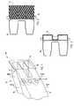
- FIG. 1is a fragmentary perspective view of a bumper system including a bumper beam and a face-mounted energy absorber;
- FIGS. 2-3are cross sections taken along the lines II—II and III—III in FIG. 1;
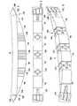
- FIG. 4is a front perspective view of a second bumper system including a bumper beam and a modified face-mounted energy absorber;
- FIG. 5is a rear perspective view of the energy absorber shown in FIG. 4;
- FIG. 6is a top view of FIG. 4;
- FIG. 7is a rear view of FIG. 5;
- FIGS. 8-9are front and top views of a third bumper system
- FIGS. 10-11are front and rear perspective view of the energy absorber shown in FIG. 8.
- FIG. 12is a front perspective view of an injection molded solid plastic component of the energy absorber shown in FIGS. 10 — 11 .
- a bumper system 8(FIG. 1) includes a bumper beam 16 having a face and ends, and an energy absorber 10 mounted on the face.
- the energy absorberhas a center-located foam piece 11 engaging the face and an injection-molded end piece 12 securely attached to each end of the foam piece and also engaging the face.
- the energy absorber 10is adapted to advantageously use a common center piece 11 made of foam, and any one of a variety of different injection-molded end pieces attached to the foam.
- the illustrated end piece 12includes loops or attachment flanges 13 and is insert-molded onto an end of the foam piece 11 when forming the foam piece 11 .
- the end piece 12includes a front surface 14 angled to match the corner of its particular vehicle, and a notched back surface 15 shaped to mateably receive an end of the bumper beam 16 that it rides on. It is contemplated that different attachment means can be used to attach pieces 11 and 12 together, including adhesive, mechanical attachment, different tabs for insert-molding into the foam, and barb-like tabs that can be poked into the foam, etc.
- a second energy absorber 10 A(FIGS. 4-7) is mounted to a face of a bumper beam 8 and includes a center-located injection-molded non-foam plastic center piece 20 , foam pieces 11 attached to each end of the center piece 20 , and injection-molded non-foam end pieces 12 attached to outer ends of each of the foam pieces 11 .
- the pieces 11 , 12 , and 20are each molded for optimal localized energy absorption (i.e. for an optimal force versus deflection curve, as well as for total energy absorption based on localized/area-specific impacts and based on particular types of impacts).
- the injection-molded pieces 12 and 20include a plurality of interconnected webs forming a honeycomb structure capable of substantial energy absorption prior to deflection of the bumper beam itself.
- a modified bumper system(FIGS. 8-9) includes a roll-formed B-shaped bumper beam 16 and a modified energy absorber 30 B abutted against its face surface.
- the energy absorber 30 B(FIGS. 10-11) includes an injection-molded piece 31 B, and multiple foam pieces 11 B molded onto the injection-molded piece 31 B.
- the injection-molded piece 31 B(FIG. 12) is molded of a non-foamed “solid” polymer and includes molded end sections 32 B (similar to end pieces 12 ), and molded center and intermediate sections 33 B and 34 B, all interconnected by longitudinal straps 35 B.
- the end sections 32 Beach include a triangular outer portion 36 B and a triangular inner portion 37 B forming a rearwardly-swept angled front surface 38 B and a stepped back surface 39 B with a pocket 40 B shaped to receive the end of the beam 16 .
- the outer portion 36 Bincludes four parallel walls 41 B that extend parallel a length of the beam 16 , and that combine with angled walls 42 B and 43 B to define a honeycomb-like structure in the form of three forwardly open pockets 44 B.
- the inner portion 37 Bhas four parallel walls 45 B that combine with angled walls 46 B and 47 B to define a rigid structure on the face of the end of the bumper beam 16 .
- the honeycomb-like structure of the outer portion 36 B and the inner portion 37 Bcombine to provide optimal energy absorption at ends of the bumper beam 16 for optimal corner impact resistance and crush characteristics.
- the walls 41 B and 45 Bare generally parallel and aligned with each other and extend in a horizontal plane (when in a car-mounted position), such that good corner impact strength is provided. It is noted that the inner and outer portions 36 B and 37 B are configured to allow a simple molding die, without the need for making undercuts, blind surfaces, and without the need for complex die pulls and slides.
- the center and intermediate sections 33 B and 34 Beach comprise rearwardly-open box-shaped sections formed by side walls 50 B, a top wall 51 B, a bottom wall 52 B and a front wall 53 B.
- An opening 54 Bis formed in each of the front walls 53 B, and a centered tubular “crush tower” of material 55 B extends rearwardly from the marginal material forming the opening 54 B to a rear of the energy absorber.
- the box-like shape of walls 50 B/ 51 B/ 52 B/ 53 B along with the crush tower 55 Badds considerably to the impact strength of the energy absorber 30 B and adds to control over the crush sequence and characteristics of impact and bumper system crush stroke versus energy absorption.
- the crush sequencehas a stepped function, where the initial crush strength is a little lower, and when energy absorber 30 B crushes to the point where the crush tower 55 B hits the bumper beam 16 , the impact strength suddenly increases for additional crush stroke distances. Also, the top and bottom walls 51 B and 52 B are wavy or undulated to provide increased impact strength.
- the straps 35 Bextend between and interconnect each of the sections 32 B, 33 B, and 34 B. Their cross sections define a rearwardly-facing U-shape, and are formed by front wall 57 B, and top and bottom walls 58 B and 59 B.
- the straps 35 Bpermit flexing movement, until the foam sections 11 B are molded onto the pieces 31 B, at which time the energy absorber 30 B becomes stiff enough to easily handle and assemble onto the bumper beam 16 .
- the entire illustrated energy absorber 30 Bis configured so that it can be molded by a relatively simple molding die, where the die does not include draws, slides, and other moving complex components for making blind and/or hidden surfaces. This greatly simplifies and improve tooling, and reduces costs of making the die and keeping the die maintained and operational.
Landscapes
- Engineering & Computer Science (AREA)
- Mechanical Engineering (AREA)
- Vibration Dampers (AREA)
Abstract
Description
This application claims benefit of provisional application serial No. 60/349,004, filed Jan. 14, 2002, entitled BUMPER WITH FOAM AND INTEGRALLY-ATTACHED INJECTION-MOLDED PIECES.
The present invention relates to vehicle bumper systems having an energy absorber on a bumper beam, and more particularly relates to a bumper system having an energy absorber on the beam that is adapted to provide different levels of energy absorption in selected areas but further adapted to take maximum advantage of mass production.
Vehicle bumper systems often include a bumper beam for strength and a mounted energy absorber to help absorb energy and distribute stress across the bumper beam during impact. However, each different model vehicle requires a slightly different shape or different energy absorption profile, such that each different model vehicle requires a different mold for the energy absorber. Each additional mold is expensive, because they are relatively large and long. Further, it takes time and labor to change molds, and requires downtime of the molding machine.
Accordingly, a bumper system is desired that includes an energy absorber solving the aforementioned problems and having the aforementioned advantages.
In one aspect of the present invention, a bumper system includes a bumper beam having a face and ends, and an energy absorber mounted on the face. The energy absorber has a foam piece engaging the face and an injection-molded end piece securely attached to an end of the foam piece and also engaging the face.
In another aspect of the present invention, a bumper system includes a bumper beam having a face and ends, and an energy absorber mounted on the face. The energy absorber has at least one foam piece engaging the face and at least one non-foam plastic piece securely attached to an end of the foam piece and also engaging the face. The foam piece and the non-foam piece form a single member that can be handled and attached as a unit to the bumper beam.
In another aspect of the present invention, a method comprises steps of molding a non-foam plastic component. The method further includes molding a foam component and attaching the non-foam plastic component to the foam component to form a unitary member that can be handled as a unit. The method still further includes engaging the unitary member against a face of a bumper beam.
In another aspect of the present invention, a bumper system includes a bumper beam having a face surface, and an energy absorber engaging the face surface. The energy absorber has an elongated non-foam injection-molded component with at least three longitudinally-spaced enlarged sections and further has a plurality of foam sections attached to the molded components between the enlarged sections.
These and other aspects, objects, and features of the present invention will be understood and appreciated by those skilled in the art upon studying the following specification, claims, and appended drawings.
FIG. 1 is a fragmentary perspective view of a bumper system including a bumper beam and a face-mounted energy absorber;
FIGS. 2-3 are cross sections taken along the lines II—II and III—III in FIG. 1;
FIG. 4 is a front perspective view of a second bumper system including a bumper beam and a modified face-mounted energy absorber;
FIG. 5 is a rear perspective view of the energy absorber shown in FIG. 4;
FIG. 6 is a top view of FIG. 4;
FIG. 7 is a rear view of FIG. 5;
FIGS. 8-9 are front and top views of a third bumper system;
FIGS. 10-11 are front and rear perspective view of the energy absorber shown in FIG. 8; and
FIG. 12 is a front perspective view of an injection molded solid plastic component of the energy absorber shown in FIGS.10—11.
A bumper system8 (FIG. 1) includes abumper beam 16 having a face and ends, and an energy absorber10 mounted on the face. The energy absorber has a center-locatedfoam piece 11 engaging the face and an injection-moldedend piece 12 securely attached to each end of the foam piece and also engaging the face. By this arrangement, the energy absorber is a single unit that can be handled and attached to the bumper beam, and also the energy absorber can include different end pieces while still using the same foam piece.
More specifically, the energy absorber10 is adapted to advantageously use acommon center piece 11 made of foam, and any one of a variety of different injection-molded end pieces attached to the foam. The illustratedend piece 12 includes loops orattachment flanges 13 and is insert-molded onto an end of thefoam piece 11 when forming thefoam piece 11. Theend piece 12 includes afront surface 14 angled to match the corner of its particular vehicle, and a notchedback surface 15 shaped to mateably receive an end of thebumper beam 16 that it rides on. It is contemplated that different attachment means can be used to attachpieces
A second energy absorber10A (FIGS. 4-7) is mounted to a face of abumper beam 8 and includes a center-located injection-molded non-foamplastic center piece 20,foam pieces 11 attached to each end of thecenter piece 20, and injection-moldednon-foam end pieces 12 attached to outer ends of each of thefoam pieces 11. Thepieces pieces
A modified bumper system (FIGS. 8-9) includes a roll-formed B-shaped bumper beam 16 and a modified energy absorber30B abutted against its face surface. The energy absorber30B (FIGS. 10-11) includes an injection-moldedpiece 31B, andmultiple foam pieces 11B molded onto the injection-moldedpiece 31B. The injection-moldedpiece 31B (FIG. 12) is molded of a non-foamed “solid” polymer and includes moldedend sections 32B (similar to end pieces12), and molded center andintermediate sections longitudinal straps 35B. Theend sections 32B each include a triangularouter portion 36B and a triangularinner portion 37B forming a rearwardly-sweptangled front surface 38B and a steppedback surface 39B with apocket 40B shaped to receive the end of thebeam 16. Theouter portion 36B includes fourparallel walls 41B that extend parallel a length of thebeam 16, and that combine withangled walls open pockets 44B. Theinner portion 37B has fourparallel walls 45B that combine withangled walls bumper beam 16. The honeycomb-like structure of theouter portion 36B and theinner portion 37B combine to provide optimal energy absorption at ends of thebumper beam 16 for optimal corner impact resistance and crush characteristics. Thewalls outer portions
The center andintermediate sections side walls 50B, atop wall 51B, abottom wall 52B and afront wall 53B. An opening54B is formed in each of thefront walls 53B, and a centered tubular “crush tower” ofmaterial 55B extends rearwardly from the marginal material forming the opening54B to a rear of the energy absorber. The box-like shape ofwalls 50B/51B/52B/53B along with thecrush tower 55B adds considerably to the impact strength of the energy absorber30B and adds to control over the crush sequence and characteristics of impact and bumper system crush stroke versus energy absorption. If thecrush tower 55B ends short of thebumper beam 16, then the crush sequence has a stepped function, where the initial crush strength is a little lower, and when energy absorber30B crushes to the point where thecrush tower 55B hits thebumper beam 16, the impact strength suddenly increases for additional crush stroke distances. Also, the top andbottom walls
Thestraps 35B (FIG. 12) extend between and interconnect each of thesections front wall 57B, and top andbottom walls straps 35B permit flexing movement, until thefoam sections 11B are molded onto thepieces 31B, at which time the energy absorber30B becomes stiff enough to easily handle and assemble onto thebumper beam 16.
It is noted that the entire illustrated energy absorber30B is configured so that it can be molded by a relatively simple molding die, where the die does not include draws, slides, and other moving complex components for making blind and/or hidden surfaces. This greatly simplifies and improve tooling, and reduces costs of making the die and keeping the die maintained and operational.
It is to be understood that variations and modifications can be made on the aforementioned structure without departing from the concepts of the present invention, and further it is to be understood that such concepts are intended to be covered by the following claims unless these claims by their language expressly state otherwise.
Claims (16)
1. A bumper system comprising:
a bumper beam having a face and ends; and
an energy absorber mounted on the face, the energy absorber having a foam piece engaging the face and an injection-molded end piece securely attached to an end of the foam piece and also engaging the face.
2. The bumper system defined inclaim 1 , wherein the injection-molded end piece includes attachment flanges that extend into the foam piece and anchor the injection-molded end piece in the foam piece.
3. The bumper system defined inclaim 1 , wherein the injection-molded end piece is insert-molded into the foam piece during the process of molding the foam piece.
4. The bumper system defined inclaim 1 , including a second injection-molded piece securely attached to a second end of the foam piece.
5. The bumper system defined inclaim 4 , wherein the second injection-molded piece comprises a second injection-molded end piece.
6. The bumper system defined inclaim 5 , including a second foam piece and a center-located third injection-molded piece, the first and second foam pieces being securely attached to ends of the center-located third injection-molded piece, and the first and second end pieces being attached to outer ends of the first and second foam pieces, respectively.
7. A bumper system comprising:
a bumper beam having a face and ends; and
an energy absorber mounted on the face, the energy absorber having at least one foam piece engaging the face and at least one non-foam plastic piece securely attached to an end of the foam piece and also engaging the face, the foam piece and the non-foam piece forming a single member that can be handled and attached as a unit to the bumper beam.
8. A bumper system comprising:
a bumper beam having a face surface; and
an energy absorber engaging the face surface, the energy absorber having an elongated non-foam component with at least three longitudinally-spaced enlarged sections and a plurality of foam sections attached to the non-foam component between the enlarged sections, at least one of the enlarged sections including a front wall with marginal material forming an opening therein.
9. The bumper system defined inclaim 8 , wherein the foam sections each fill a space defined between sides of the adjacent enlarged sections.
10. The bumper system defined inclaim 8 , wherein the enlarged sections are each box-shaped and have a hollow interior space.
11. A bumper system comprising:
a bumper beam having a face surface; and
an energy absorber engaging the face surface, the energy absorber having an elongated non-foam injection-molded component with at least three longitudinally-spaced enlarged sections and a plurality of foam sections attached to the molded component between the enlarged sections;
wherein the enlarged sections are each box-shaped and have a hollow interior space, and further wherein the enlarged sections each include a front wall with marginal material forming an opening therein.
12. The bumper system defined inclaim 11 , including a crush tower tube that extends from the marginal material rearwardly toward the bumper beam.
13. The bumper system defined inclaim 8 , wherein the non-foam component is one-piece and the enlarged sections are interconnected by connecting straps.
14. The bumper system defined inclaim 8 , wherein the non-foam component includes end piece sections and wherein the enlarged sections include at least one centered box-shaped section.
15. The bumper system defined inclaim 8 , wherein a front surface of the energy absorber includes first areas defined by the non-foam component, and further includes second areas defined by the foamed sections.
16. The bumper system defined inclaim 8 , wherein the non-foam component includes end sections each having a pocket shaped to receive an end of the bumper beam.
Priority Applications (1)
| Application Number | Priority Date | Filing Date | Title |
|---|---|---|---|
| US10/105,111US6644701B2 (en) | 2002-01-14 | 2002-03-22 | Bumper energy absorber with foam and non-foam pieces |
Applications Claiming Priority (2)
| Application Number | Priority Date | Filing Date | Title |
|---|---|---|---|
| US34900402P | 2002-01-14 | 2002-01-14 | |
| US10/105,111US6644701B2 (en) | 2002-01-14 | 2002-03-22 | Bumper energy absorber with foam and non-foam pieces |
Publications (2)
| Publication Number | Publication Date |
|---|---|
| US20030132640A1 US20030132640A1 (en) | 2003-07-17 |
| US6644701B2true US6644701B2 (en) | 2003-11-11 |
Family
ID=26802264
Family Applications (1)
| Application Number | Title | Priority Date | Filing Date |
|---|---|---|---|
| US10/105,111Expired - Fee RelatedUS6644701B2 (en) | 2002-01-14 | 2002-03-22 | Bumper energy absorber with foam and non-foam pieces |
Country Status (1)
| Country | Link |
|---|---|
| US (1) | US6644701B2 (en) |
Cited By (30)
| Publication number | Priority date | Publication date | Assignee | Title |
|---|---|---|---|---|
| US20030163873A1 (en)* | 2000-10-03 | 2003-09-04 | Price Christopher George | Impact-absorbing unit |
| US20030173787A1 (en)* | 2002-03-13 | 2003-09-18 | Peguform Gmbh & Co. Kg | Bumper with crash absorbing element |
| US6817638B1 (en)* | 2003-06-27 | 2004-11-16 | Hanwha L&C Corporation | Bumper system |
| WO2005012043A1 (en)* | 2003-07-03 | 2005-02-10 | Netshape International, Llc | Bumper system incorporating thermoformed energy absorber |
| US20050029821A1 (en)* | 2002-06-06 | 2005-02-10 | Darin Evans | Bumper with integrally formed energy absorber |
| US20050236850A1 (en)* | 2004-04-13 | 2005-10-27 | Darin Evans | Bumper with nesting energy-absorbing end piece |
| US20060001277A1 (en)* | 2004-07-01 | 2006-01-05 | Mellis Jeffrey J | Bumper system for a motor vehicle |
| US20060113779A1 (en)* | 2004-12-01 | 2006-06-01 | Park Kwan H | Crash acceleration pulse control block for vehicle |
| US20060125250A1 (en)* | 2004-12-13 | 2006-06-15 | Darin Evans | Bumper for pedestrian impact having thermoformed energy absorber |
| US7066508B1 (en)* | 2005-03-31 | 2006-06-27 | Ford Global Technologies, Llc | Bumper cross-section with hinges |
| US20060175848A1 (en)* | 2005-02-03 | 2006-08-10 | Akad Osman E | Impact energy absorbing crash cushion |
| US20060255602A1 (en)* | 2005-05-02 | 2006-11-16 | Darin Evans | Hybrid bumper with trim |
| US7172227B2 (en) | 2002-06-06 | 2007-02-06 | Netshape International, Llc | Bumper system with energy absorber |
| US20080054655A1 (en)* | 2006-08-31 | 2008-03-06 | Mazda Motor Corporation | Vehicle bumper structure |
| US20080309102A1 (en)* | 2006-09-27 | 2008-12-18 | Sergio Sampaio | Vehicle bumper structure |
| US20090026778A1 (en)* | 2007-07-27 | 2009-01-29 | Tokai Rubber Industries, Ltd. | Impact absorbing member and manufacturing method thereof |
| US20090160204A1 (en)* | 2007-12-21 | 2009-06-25 | Brian Joseph Czopek | Corner energy absorber and bumper system |
| US20090206618A1 (en)* | 2008-02-14 | 2009-08-20 | Ralston Daniel D | Energy absorber with sidewall stabilizer ribs |
| US20090230589A1 (en)* | 2008-03-11 | 2009-09-17 | Rossi Michael A | Thermoformed component with integral attachment structure and method |
| US7866716B2 (en) | 2008-04-08 | 2011-01-11 | Flex-N-Gate Corporation | Energy absorber for vehicle |
| US20110109105A1 (en)* | 2009-11-06 | 2011-05-12 | Daniel Ralston | Energy absorber with lobes providing uniform pedestrian impact |
| US20110214932A1 (en)* | 2010-03-05 | 2011-09-08 | Daniel Ralston | Hood pedestrian energy absorber |
| US8123263B2 (en) | 2001-09-27 | 2012-02-28 | Shape Corp. | Energy management beam |
| US20120228888A1 (en)* | 2009-11-12 | 2012-09-13 | Magna Steyr Fahrzeugtechnik Ag & Co Kg | Modular bumper arrangement for a vehicle |
| US8424629B2 (en) | 2011-03-09 | 2013-04-23 | Shape Corp. | Vehicle energy absorber for pedestrian's upper leg |
| US20130241218A1 (en)* | 2012-03-14 | 2013-09-19 | Aisin Keikinzoku Kabushiki Kaisha | Vehicle bumper reinforcement |
| US20140001780A1 (en)* | 2011-03-15 | 2014-01-02 | Toyota Jidosha Kabushiki Kaisha | Bumper structure |
| US8973957B2 (en) | 2013-04-22 | 2015-03-10 | Shape Corp. | Bumper energy absorber with sensor and configured lobes |
| US9487170B2 (en) | 2013-07-22 | 2016-11-08 | Darin Evans | Truck bumper shell and method of retrofit installation |
| US10065587B2 (en) | 2015-11-23 | 2018-09-04 | Flex|N|Gate Corporation | Multi-layer energy absorber |
Families Citing this family (2)
| Publication number | Priority date | Publication date | Assignee | Title |
|---|---|---|---|---|
| US20040094975A1 (en)* | 2002-11-14 | 2004-05-20 | Stephen Shuler | Hybrid bumper system |
| DE102007032031A1 (en)* | 2007-07-10 | 2009-01-15 | Dr. Ing. H.C. F. Porsche Aktiengesellschaft | Stem of a motor vehicle |
Citations (85)
| Publication number | Priority date | Publication date | Assignee | Title |
|---|---|---|---|---|
| US831755A (en) | 1902-04-12 | 1906-09-25 | Alwin Vietor | Rolled girder. |
| US1247569A (en) | 1917-06-04 | 1917-11-20 | Louis N Harvey | Bumper for automobiles. |
| US1362439A (en) | 1919-11-25 | 1920-12-14 | Alvin L Roberts | Rolled-metal section |
| USRE15255E (en) | 1921-12-27 | Bumper fob automobiles | ||
| US1429061A (en) | 1920-06-12 | 1922-09-12 | American Brass Co | Apparatus for rolling metal |
| US1499986A (en) | 1924-02-04 | 1924-07-01 | Kirsch Mfg Company | Channeled strip such as curtain rods or the like |
| FR40075E (en) | 1931-04-09 | 1932-04-20 | Bumper | |
| US1927442A (en) | 1932-04-04 | 1933-09-19 | Charles W Laufle | Trussed structure and method and shapes therefor |
| US1952545A (en) | 1931-03-07 | 1934-03-27 | Allis Chalmers Mfg Co | Method of providing grouser type track shoes |
| FR766186A (en) | 1933-12-28 | 1934-06-22 | Amortisseur Apex L | Detachable bumper device |
| GB563548A (en) | 1943-04-07 | 1944-08-18 | Orlit Ltd | Improved method of and means for polishing tiles and the like |
| US2371671A (en) | 1943-03-23 | 1945-03-20 | Western Electric Co | Metal rolling process |
| GB645721A (en) | 1948-02-23 | 1950-11-08 | Duo Rubber And Engineering Com | Improvements relating to amusement cars |
| US2734407A (en) | 1956-02-14 | Taper rolling mill | ||
| US3392566A (en) | 1961-07-03 | 1968-07-16 | Lodge & Shipley Co | Metal rolling |
| US3596963A (en) | 1969-07-22 | 1971-08-03 | Francis Lee Phillips | Breakable bumper extension |
| US3762195A (en) | 1970-03-09 | 1973-10-02 | Hitachi Ltd | Thickness control apparatus for rolling mill |
| US3768850A (en) | 1971-11-24 | 1973-10-30 | Ford Motor Co | Pneumatic flexible bumper |
| US3777438A (en) | 1971-08-30 | 1973-12-11 | R Brown | Ornamental protective rail |
| US3860279A (en)* | 1973-01-15 | 1975-01-14 | Mccord Corp | Resilient energy absorbing bumper assembly |
| GB1382693A (en) | 1971-10-21 | 1975-02-05 | Subsea Equipment Ass Ltd | Method of connecting underwater installations |
| US3884517A (en) | 1973-07-25 | 1975-05-20 | Spydell Davidson | Safety bumper for trucks |
| US3902748A (en) | 1973-12-12 | 1975-09-02 | Firestone Tire & Rubber Co | Pneumatic energy absorbing bumper system for motor vehicles |
| US3989292A (en) | 1973-12-12 | 1976-11-02 | The Firestone Tire & Rubber Company | Semi-pneumatic energy absorbing bumper system for motor vehicles |
| US4013317A (en) | 1973-04-16 | 1977-03-22 | Daimler-Benz Aktiengesellschaft | Lateral protection for motor vehicles |
| US4022505A (en) | 1975-11-28 | 1977-05-10 | General Motors Corporation | Energy absorbing cellular media for vehicles |
| US4066285A (en) | 1976-12-09 | 1978-01-03 | Trim-Line, Inc. | Ornamental protective trim strip for motor vehicles |
| US4072334A (en)* | 1975-07-21 | 1978-02-07 | Energy Absorption Systems, Inc. | Energy absorbing bumper |
| US4095831A (en) | 1975-12-09 | 1978-06-20 | Nissan Motor Company, Limited | Vehicle bumper device |
| US4111478A (en) | 1976-02-05 | 1978-09-05 | Paulstra | System for controlling the deformation of side elements of vehicle bumpers |
| GB2027516A (en) | 1978-08-03 | 1980-02-20 | Mccord Corp | Energy-absorbing assembly |
| US4225167A (en) | 1978-03-06 | 1980-09-30 | Buettner Carl F | Vehicle bumpers with collapsible parts |
| US4233833A (en) | 1978-06-05 | 1980-11-18 | United States Gypsum Company | Method for stretching sheet metal and structural members formed therefrom |
| US4241146A (en) | 1978-11-20 | 1980-12-23 | Eugene W. Sivachenko | Corrugated plate having variable material thickness and method for making same |
| US4248072A (en) | 1978-07-25 | 1981-02-03 | Aichi Steel Works, Limited | Method of and apparatus for producing plate material having uniform width and lengthwise thickness variation |
| US4291564A (en) | 1978-12-21 | 1981-09-29 | Schloemann-Siemag Aktiengesellschaft | Method of and apparatus for rolling sheet steel profiles of different cross-sectional shape in universal beam rolling mill trains |
| US4317350A (en) | 1978-11-20 | 1982-03-02 | E. W. Sivachenko | Corrugated plate having variable material thickness and method for making same |
| US4320913A (en) | 1979-10-26 | 1982-03-23 | Shigeharu Kuroda | Shock absorbing bumper for vehicles |
| US4333674A (en) | 1978-03-06 | 1982-06-08 | Buettner Carl F | Vehicle bumpers with collapsible parts |
| US4361352A (en) | 1979-05-21 | 1982-11-30 | Aisin Seiki Kabushiki Kaisha | Bumper for vehicles |
| US4386799A (en) | 1981-01-26 | 1983-06-07 | Molnar Industries, Inc. | Shock absorbing device having predictable deflection characteristics |
| US4413856A (en) | 1981-08-07 | 1983-11-08 | General Motors Corporation | Hardbar energy absorbing bumper system for vehicles |
| US4422680A (en) | 1980-06-03 | 1983-12-27 | Regie Nationale Des Usines Renault | Energy absorbing curved sections |
| US4433565A (en) | 1978-03-30 | 1984-02-28 | Theodor Wuppermann Gmbh | Method of and apparatus for the manufacturing of metal profile members, especially steel profile members |
| DE3343709A1 (en) | 1982-12-16 | 1984-06-20 | Nissan Motor Co., Ltd., Yokohama, Kanagawa | Process for shaping a frame part |
| US4578979A (en) | 1982-10-27 | 1986-04-01 | Hitachi Cables, Ltd. | Method of producing a strip having a non-uniform cross section by a rolling process |
| JPS61169350A (en) | 1985-01-23 | 1986-07-31 | Nissan Motor Co Ltd | Connecting structure between bumper main and bumper side |
| JPS61172603A (en) | 1985-01-29 | 1986-08-04 | Sumitomo Metal Ind Ltd | Thick plate rolling method |
| US4684166A (en) | 1986-05-19 | 1987-08-04 | General Motors Corporation | Vehicle door impact beam and stabilizing assembly |
| US4714287A (en) | 1985-03-23 | 1987-12-22 | Daimler-Benz Aktiengesellschaft | Bending bar to be used as a bumper of a vehicle |
| US4715630A (en) | 1986-04-28 | 1987-12-29 | Transpec Inc. | Energy absorbing vehicle bumper |
| US4783104A (en) | 1986-02-17 | 1988-11-08 | Nissan Motor Company, Ltd. | Bumper assembly |
| US4796946A (en) | 1987-09-04 | 1989-01-10 | Inland Steel Company | Automotive vehicle door and bar reinforcement |
| JPS6466008A (en) | 1987-09-03 | 1989-03-13 | Kawasaki Steel Co | Method for rolling sheet material |
| US4811979A (en) | 1986-07-04 | 1989-03-14 | Dr. Ing. H.C.F. Porsche Aktiengesellschaft | Bumper for vehicles |
| US4862666A (en) | 1987-02-16 | 1989-09-05 | Plannja Ab | Profiled sheet for building purposes |
| JPH01240322A (en) | 1988-03-22 | 1989-09-25 | Daiwa Kogyo Kk | Door guard bar for automobile |
| US5040399A (en) | 1989-06-30 | 1991-08-20 | Hoesch Ag | Method of fabricating box section from steel with walls that differ in thickness |
| JPH03227750A (en) | 1990-01-31 | 1991-10-08 | Suzuki Motor Corp | Car bumper |
| US5154462A (en) | 1991-12-23 | 1992-10-13 | Ford Motor Company | Method for making a bonded vehicular cross member bumper beam from two materials |
| US5180629A (en) | 1990-06-27 | 1993-01-19 | Nissan Motor Co., Ltd. | Injection-molded article |
| JPH0524291A (en) | 1991-07-22 | 1993-02-02 | Brother Ind Ltd | Tape cassette |
| US5232261A (en) | 1992-06-04 | 1993-08-03 | Nhk Spring Co., Ltd. | Door impact beam for an automobile |
| US5277469A (en) | 1989-10-26 | 1994-01-11 | Mannesmann Aktiengesellschaft | Motor vehicle door reinforcement tube and a process for manufacturing the reinforcement tube |
| US5340178A (en) | 1993-11-12 | 1994-08-23 | Chrysler Corporation | Vehicle bumper beam |
| JPH06286536A (en) | 1993-03-31 | 1994-10-11 | Furukawa Alum Co Ltd | Bumper reinforcement structure body |
| US5385375A (en) | 1992-11-23 | 1995-01-31 | General Motors Corporation | Reinforced impact beam for a bumper assembly and method of manufacture |
| US5404974A (en) | 1992-03-25 | 1995-04-11 | Volkswagen Ag | Impact-absorbing transverse support arrangement |
| US5407239A (en) | 1991-11-25 | 1995-04-18 | Honda Giken Kogyo Kabushiki Kaisha | Vehicle bumper beam and method of fabricating the same |
| US5540016A (en) | 1990-01-09 | 1996-07-30 | Norsk Hydro A.S. | Structural beam |
| US5545361A (en) | 1994-02-10 | 1996-08-13 | Shape Corporation | Method of making a vehicle bumper with foam therein using a deformable plug |
| US5560662A (en) | 1993-12-29 | 1996-10-01 | Boda Industries, Inc. | Vehicle bumper cover |
| US5672405A (en) | 1996-02-26 | 1997-09-30 | Plank, Jr.; J. Lee | Metal-reinforced molded-plastic composite structures |
| US5756167A (en) | 1995-04-07 | 1998-05-26 | Hashimoto Forming Industry Co., Ltd. | Rigid elongated member for use in vehicles and producing method and apparatus therefor |
| US5785376A (en) | 1995-06-21 | 1998-07-28 | Mascotech Tubular Products, Inc. | Vehicle door beam |
| US5799991A (en) | 1996-10-23 | 1998-09-01 | Concept Analysis Corporation | Molded bumper system with reinforcement beam |
| US5813718A (en) | 1995-02-14 | 1998-09-29 | Yamakawa Industrial Co., Ltd. | Guard beam for automotive door structure |
| US5857734A (en) | 1996-03-13 | 1999-01-12 | Toyota Jidosha Kabushiki Kaisha | Energy absorbing structure for side portion of vehicle body |
| US5997058A (en) | 1996-01-24 | 1999-12-07 | Norsk Hydro Asa | Bumper, and the fabrication thereof |
| US6000738A (en) | 1998-03-13 | 1999-12-14 | Chrysler Corporation | Force-absorbing vehicle bumper |
| US6003912A (en) | 1996-04-09 | 1999-12-21 | Chrysler Corporation | Bi-metal vehicle bumper structure |
| US6042163A (en) | 1998-01-28 | 2000-03-28 | Shape Corporation | Vehicle bumper including end section and method of manufacture |
| US6138429A (en) | 1997-07-31 | 2000-10-31 | Dr. Ing. H. C. F. Porshe Ag | Cross member for vehicles and method of manufacturing same |
| US6179353B1 (en) | 1999-07-27 | 2001-01-30 | Shape Corporation | High flex bumper with reinforced corner end sections |
| US6318775B1 (en) | 1999-06-21 | 2001-11-20 | Shape Corporation | Composite bumper construction |
- 2002
- 2002-03-22USUS10/105,111patent/US6644701B2/ennot_activeExpired - Fee Related
Patent Citations (85)
| Publication number | Priority date | Publication date | Assignee | Title |
|---|---|---|---|---|
| US2734407A (en) | 1956-02-14 | Taper rolling mill | ||
| USRE15255E (en) | 1921-12-27 | Bumper fob automobiles | ||
| US831755A (en) | 1902-04-12 | 1906-09-25 | Alwin Vietor | Rolled girder. |
| US1247569A (en) | 1917-06-04 | 1917-11-20 | Louis N Harvey | Bumper for automobiles. |
| US1362439A (en) | 1919-11-25 | 1920-12-14 | Alvin L Roberts | Rolled-metal section |
| US1429061A (en) | 1920-06-12 | 1922-09-12 | American Brass Co | Apparatus for rolling metal |
| US1499986A (en) | 1924-02-04 | 1924-07-01 | Kirsch Mfg Company | Channeled strip such as curtain rods or the like |
| US1952545A (en) | 1931-03-07 | 1934-03-27 | Allis Chalmers Mfg Co | Method of providing grouser type track shoes |
| FR40075E (en) | 1931-04-09 | 1932-04-20 | Bumper | |
| US1927442A (en) | 1932-04-04 | 1933-09-19 | Charles W Laufle | Trussed structure and method and shapes therefor |
| FR766186A (en) | 1933-12-28 | 1934-06-22 | Amortisseur Apex L | Detachable bumper device |
| US2371671A (en) | 1943-03-23 | 1945-03-20 | Western Electric Co | Metal rolling process |
| GB563548A (en) | 1943-04-07 | 1944-08-18 | Orlit Ltd | Improved method of and means for polishing tiles and the like |
| GB645721A (en) | 1948-02-23 | 1950-11-08 | Duo Rubber And Engineering Com | Improvements relating to amusement cars |
| US3392566A (en) | 1961-07-03 | 1968-07-16 | Lodge & Shipley Co | Metal rolling |
| US3596963A (en) | 1969-07-22 | 1971-08-03 | Francis Lee Phillips | Breakable bumper extension |
| US3762195A (en) | 1970-03-09 | 1973-10-02 | Hitachi Ltd | Thickness control apparatus for rolling mill |
| US3777438A (en) | 1971-08-30 | 1973-12-11 | R Brown | Ornamental protective rail |
| GB1382693A (en) | 1971-10-21 | 1975-02-05 | Subsea Equipment Ass Ltd | Method of connecting underwater installations |
| US3768850A (en) | 1971-11-24 | 1973-10-30 | Ford Motor Co | Pneumatic flexible bumper |
| US3860279A (en)* | 1973-01-15 | 1975-01-14 | Mccord Corp | Resilient energy absorbing bumper assembly |
| US4013317A (en) | 1973-04-16 | 1977-03-22 | Daimler-Benz Aktiengesellschaft | Lateral protection for motor vehicles |
| US3884517A (en) | 1973-07-25 | 1975-05-20 | Spydell Davidson | Safety bumper for trucks |
| US3902748A (en) | 1973-12-12 | 1975-09-02 | Firestone Tire & Rubber Co | Pneumatic energy absorbing bumper system for motor vehicles |
| US3989292A (en) | 1973-12-12 | 1976-11-02 | The Firestone Tire & Rubber Company | Semi-pneumatic energy absorbing bumper system for motor vehicles |
| US4072334A (en)* | 1975-07-21 | 1978-02-07 | Energy Absorption Systems, Inc. | Energy absorbing bumper |
| US4022505A (en) | 1975-11-28 | 1977-05-10 | General Motors Corporation | Energy absorbing cellular media for vehicles |
| US4095831A (en) | 1975-12-09 | 1978-06-20 | Nissan Motor Company, Limited | Vehicle bumper device |
| US4111478A (en) | 1976-02-05 | 1978-09-05 | Paulstra | System for controlling the deformation of side elements of vehicle bumpers |
| US4066285A (en) | 1976-12-09 | 1978-01-03 | Trim-Line, Inc. | Ornamental protective trim strip for motor vehicles |
| US4225167A (en) | 1978-03-06 | 1980-09-30 | Buettner Carl F | Vehicle bumpers with collapsible parts |
| US4333674A (en) | 1978-03-06 | 1982-06-08 | Buettner Carl F | Vehicle bumpers with collapsible parts |
| US4433565A (en) | 1978-03-30 | 1984-02-28 | Theodor Wuppermann Gmbh | Method of and apparatus for the manufacturing of metal profile members, especially steel profile members |
| US4233833A (en) | 1978-06-05 | 1980-11-18 | United States Gypsum Company | Method for stretching sheet metal and structural members formed therefrom |
| US4248072A (en) | 1978-07-25 | 1981-02-03 | Aichi Steel Works, Limited | Method of and apparatus for producing plate material having uniform width and lengthwise thickness variation |
| GB2027516A (en) | 1978-08-03 | 1980-02-20 | Mccord Corp | Energy-absorbing assembly |
| US4241146A (en) | 1978-11-20 | 1980-12-23 | Eugene W. Sivachenko | Corrugated plate having variable material thickness and method for making same |
| US4317350A (en) | 1978-11-20 | 1982-03-02 | E. W. Sivachenko | Corrugated plate having variable material thickness and method for making same |
| US4291564A (en) | 1978-12-21 | 1981-09-29 | Schloemann-Siemag Aktiengesellschaft | Method of and apparatus for rolling sheet steel profiles of different cross-sectional shape in universal beam rolling mill trains |
| US4361352A (en) | 1979-05-21 | 1982-11-30 | Aisin Seiki Kabushiki Kaisha | Bumper for vehicles |
| US4320913A (en) | 1979-10-26 | 1982-03-23 | Shigeharu Kuroda | Shock absorbing bumper for vehicles |
| US4422680A (en) | 1980-06-03 | 1983-12-27 | Regie Nationale Des Usines Renault | Energy absorbing curved sections |
| US4386799A (en) | 1981-01-26 | 1983-06-07 | Molnar Industries, Inc. | Shock absorbing device having predictable deflection characteristics |
| US4413856A (en) | 1981-08-07 | 1983-11-08 | General Motors Corporation | Hardbar energy absorbing bumper system for vehicles |
| US4578979A (en) | 1982-10-27 | 1986-04-01 | Hitachi Cables, Ltd. | Method of producing a strip having a non-uniform cross section by a rolling process |
| DE3343709A1 (en) | 1982-12-16 | 1984-06-20 | Nissan Motor Co., Ltd., Yokohama, Kanagawa | Process for shaping a frame part |
| JPS61169350A (en) | 1985-01-23 | 1986-07-31 | Nissan Motor Co Ltd | Connecting structure between bumper main and bumper side |
| JPS61172603A (en) | 1985-01-29 | 1986-08-04 | Sumitomo Metal Ind Ltd | Thick plate rolling method |
| US4714287A (en) | 1985-03-23 | 1987-12-22 | Daimler-Benz Aktiengesellschaft | Bending bar to be used as a bumper of a vehicle |
| US4783104A (en) | 1986-02-17 | 1988-11-08 | Nissan Motor Company, Ltd. | Bumper assembly |
| US4715630A (en) | 1986-04-28 | 1987-12-29 | Transpec Inc. | Energy absorbing vehicle bumper |
| US4684166A (en) | 1986-05-19 | 1987-08-04 | General Motors Corporation | Vehicle door impact beam and stabilizing assembly |
| US4811979A (en) | 1986-07-04 | 1989-03-14 | Dr. Ing. H.C.F. Porsche Aktiengesellschaft | Bumper for vehicles |
| US4862666A (en) | 1987-02-16 | 1989-09-05 | Plannja Ab | Profiled sheet for building purposes |
| JPS6466008A (en) | 1987-09-03 | 1989-03-13 | Kawasaki Steel Co | Method for rolling sheet material |
| US4796946A (en) | 1987-09-04 | 1989-01-10 | Inland Steel Company | Automotive vehicle door and bar reinforcement |
| JPH01240322A (en) | 1988-03-22 | 1989-09-25 | Daiwa Kogyo Kk | Door guard bar for automobile |
| US5040399A (en) | 1989-06-30 | 1991-08-20 | Hoesch Ag | Method of fabricating box section from steel with walls that differ in thickness |
| US5277469A (en) | 1989-10-26 | 1994-01-11 | Mannesmann Aktiengesellschaft | Motor vehicle door reinforcement tube and a process for manufacturing the reinforcement tube |
| US5540016A (en) | 1990-01-09 | 1996-07-30 | Norsk Hydro A.S. | Structural beam |
| JPH03227750A (en) | 1990-01-31 | 1991-10-08 | Suzuki Motor Corp | Car bumper |
| US5180629A (en) | 1990-06-27 | 1993-01-19 | Nissan Motor Co., Ltd. | Injection-molded article |
| JPH0524291A (en) | 1991-07-22 | 1993-02-02 | Brother Ind Ltd | Tape cassette |
| US5407239A (en) | 1991-11-25 | 1995-04-18 | Honda Giken Kogyo Kabushiki Kaisha | Vehicle bumper beam and method of fabricating the same |
| US5154462A (en) | 1991-12-23 | 1992-10-13 | Ford Motor Company | Method for making a bonded vehicular cross member bumper beam from two materials |
| US5404974A (en) | 1992-03-25 | 1995-04-11 | Volkswagen Ag | Impact-absorbing transverse support arrangement |
| US5232261A (en) | 1992-06-04 | 1993-08-03 | Nhk Spring Co., Ltd. | Door impact beam for an automobile |
| US5385375A (en) | 1992-11-23 | 1995-01-31 | General Motors Corporation | Reinforced impact beam for a bumper assembly and method of manufacture |
| JPH06286536A (en) | 1993-03-31 | 1994-10-11 | Furukawa Alum Co Ltd | Bumper reinforcement structure body |
| US5340178A (en) | 1993-11-12 | 1994-08-23 | Chrysler Corporation | Vehicle bumper beam |
| US5560662A (en) | 1993-12-29 | 1996-10-01 | Boda Industries, Inc. | Vehicle bumper cover |
| US5545361A (en) | 1994-02-10 | 1996-08-13 | Shape Corporation | Method of making a vehicle bumper with foam therein using a deformable plug |
| US5813718A (en) | 1995-02-14 | 1998-09-29 | Yamakawa Industrial Co., Ltd. | Guard beam for automotive door structure |
| US5756167A (en) | 1995-04-07 | 1998-05-26 | Hashimoto Forming Industry Co., Ltd. | Rigid elongated member for use in vehicles and producing method and apparatus therefor |
| US5785376A (en) | 1995-06-21 | 1998-07-28 | Mascotech Tubular Products, Inc. | Vehicle door beam |
| US5997058A (en) | 1996-01-24 | 1999-12-07 | Norsk Hydro Asa | Bumper, and the fabrication thereof |
| US5672405A (en) | 1996-02-26 | 1997-09-30 | Plank, Jr.; J. Lee | Metal-reinforced molded-plastic composite structures |
| US5857734A (en) | 1996-03-13 | 1999-01-12 | Toyota Jidosha Kabushiki Kaisha | Energy absorbing structure for side portion of vehicle body |
| US6003912A (en) | 1996-04-09 | 1999-12-21 | Chrysler Corporation | Bi-metal vehicle bumper structure |
| US5799991A (en) | 1996-10-23 | 1998-09-01 | Concept Analysis Corporation | Molded bumper system with reinforcement beam |
| US6138429A (en) | 1997-07-31 | 2000-10-31 | Dr. Ing. H. C. F. Porshe Ag | Cross member for vehicles and method of manufacturing same |
| US6042163A (en) | 1998-01-28 | 2000-03-28 | Shape Corporation | Vehicle bumper including end section and method of manufacture |
| US6000738A (en) | 1998-03-13 | 1999-12-14 | Chrysler Corporation | Force-absorbing vehicle bumper |
| US6318775B1 (en) | 1999-06-21 | 2001-11-20 | Shape Corporation | Composite bumper construction |
| US6179353B1 (en) | 1999-07-27 | 2001-01-30 | Shape Corporation | High flex bumper with reinforced corner end sections |
Non-Patent Citations (1)
| Title |
|---|
| Exhibit A includes four pictures of a prior art vehicle bumper system on a 2001 Ford Focus model vehicle, which includes a steel beam and an energy absorber that wraps around ends of the beam. The energy absorber includes a lower-density black foam body and has several higher-density white foam blocks inset into an inner surface of the black foam. (Note: Photo 1 shows an "extra" energy absorber loosely setting on a rear bumper system of a Ford Focus, the "extra" energy absorber being reversed to show its inner surface with the white foam blocks exposed.). |
Cited By (55)
| Publication number | Priority date | Publication date | Assignee | Title |
|---|---|---|---|---|
| US20030163873A1 (en)* | 2000-10-03 | 2003-09-04 | Price Christopher George | Impact-absorbing unit |
| US8123263B2 (en) | 2001-09-27 | 2012-02-28 | Shape Corp. | Energy management beam |
| US6926321B2 (en)* | 2002-03-13 | 2005-08-09 | Peguform Gmbh | Bumper with crash absorbing element |
| US20030173787A1 (en)* | 2002-03-13 | 2003-09-18 | Peguform Gmbh & Co. Kg | Bumper with crash absorbing element |
| US7172227B2 (en) | 2002-06-06 | 2007-02-06 | Netshape International, Llc | Bumper system with energy absorber |
| US20050029821A1 (en)* | 2002-06-06 | 2005-02-10 | Darin Evans | Bumper with integrally formed energy absorber |
| US6926323B2 (en)* | 2002-06-06 | 2005-08-09 | Netshape International, Llc | Bumper with integrally formed energy absorber |
| US7340833B2 (en) | 2002-06-06 | 2008-03-11 | Netshape Energy Management Llc | Bumper system with energy absorber |
| US6817638B1 (en)* | 2003-06-27 | 2004-11-16 | Hanwha L&C Corporation | Bumper system |
| US20070108778A1 (en)* | 2003-07-03 | 2007-05-17 | Darin Evans | Bumper system incorporating thermoformed energy absorber |
| WO2005012043A1 (en)* | 2003-07-03 | 2005-02-10 | Netshape International, Llc | Bumper system incorporating thermoformed energy absorber |
| US7494165B2 (en) | 2003-07-03 | 2009-02-24 | Netshape Energy Management Llc | Method of making bumper system using thermoformed component |
| US7222897B2 (en) | 2003-07-03 | 2007-05-29 | Netshape Energy Management Llc | Method of constructing bumper incorporating thermoformed energy absorber |
| US7131674B2 (en) | 2003-07-03 | 2006-11-07 | Netshape International, Llc | Bumper system incorporating thermoformed energy absorber |
| US20050236850A1 (en)* | 2004-04-13 | 2005-10-27 | Darin Evans | Bumper with nesting energy-absorbing end piece |
| US7147258B2 (en) | 2004-04-13 | 2006-12-12 | Netshape International, Llc | Bumper with nesting energy-absorbing end piece |
| US20060001277A1 (en)* | 2004-07-01 | 2006-01-05 | Mellis Jeffrey J | Bumper system for a motor vehicle |
| US7399014B2 (en) | 2004-07-01 | 2008-07-15 | Magna International Inc. | Bumper system for a motor vehicle |
| US7275775B2 (en)* | 2004-12-01 | 2007-10-02 | Hyundai Motor Company | Crash acceleration pulse control block for vehicle |
| US20060113779A1 (en)* | 2004-12-01 | 2006-06-01 | Park Kwan H | Crash acceleration pulse control block for vehicle |
| US7163243B2 (en) | 2004-12-13 | 2007-01-16 | Netshape International, Llc | Bumper for pedestrian impact having thermoformed energy absorber |
| US20060125250A1 (en)* | 2004-12-13 | 2006-06-15 | Darin Evans | Bumper for pedestrian impact having thermoformed energy absorber |
| US7261345B2 (en) | 2005-02-03 | 2007-08-28 | Akad Osman E | Impact energy absorbing crash cushion |
| US20060175848A1 (en)* | 2005-02-03 | 2006-08-10 | Akad Osman E | Impact energy absorbing crash cushion |
| US7066508B1 (en)* | 2005-03-31 | 2006-06-27 | Ford Global Technologies, Llc | Bumper cross-section with hinges |
| US7552955B2 (en)* | 2005-05-02 | 2009-06-30 | Netshape Energy Management, Llc | Hybrid bumper with trim |
| US20060255602A1 (en)* | 2005-05-02 | 2006-11-16 | Darin Evans | Hybrid bumper with trim |
| US20080054655A1 (en)* | 2006-08-31 | 2008-03-06 | Mazda Motor Corporation | Vehicle bumper structure |
| US8662546B2 (en)* | 2006-08-31 | 2014-03-04 | Mazda Motor Corporation | Vehicle bumper structure |
| US20080309102A1 (en)* | 2006-09-27 | 2008-12-18 | Sergio Sampaio | Vehicle bumper structure |
| US7726709B2 (en)* | 2006-09-27 | 2010-06-01 | Toyota Jidosha Kabushiki Kaisha | Vehicle bumper structure |
| US20090026778A1 (en)* | 2007-07-27 | 2009-01-29 | Tokai Rubber Industries, Ltd. | Impact absorbing member and manufacturing method thereof |
| US8505990B2 (en)* | 2007-12-21 | 2013-08-13 | Sabic Innovative Plastics Ip B.V. | Corner energy absorber and bumper system |
| US20090160204A1 (en)* | 2007-12-21 | 2009-06-25 | Brian Joseph Czopek | Corner energy absorber and bumper system |
| US20090206618A1 (en)* | 2008-02-14 | 2009-08-20 | Ralston Daniel D | Energy absorber with sidewall stabilizer ribs |
| US8016331B2 (en) | 2008-02-14 | 2011-09-13 | Shape Corp. | Energy absorber with sidewall stabilizer ribs |
| US20090230589A1 (en)* | 2008-03-11 | 2009-09-17 | Rossi Michael A | Thermoformed component with integral attachment structure and method |
| US20100015387A1 (en)* | 2008-03-11 | 2010-01-21 | Rossi Michael A | Thermoformed product with coined region |
| US7857610B2 (en) | 2008-03-11 | 2010-12-28 | Safetynet Energy Management, Llc | Apparatus making thermoformed component with integral coined structure |
| US7993725B2 (en) | 2008-03-11 | 2011-08-09 | Safetynet Energy Management, Llc | Thermoformed product with coined region |
| US7866716B2 (en) | 2008-04-08 | 2011-01-11 | Flex-N-Gate Corporation | Energy absorber for vehicle |
| US20110109105A1 (en)* | 2009-11-06 | 2011-05-12 | Daniel Ralston | Energy absorber with lobes providing uniform pedestrian impact |
| US8196979B2 (en) | 2009-11-06 | 2012-06-12 | Shape Corp. | Energy absorber with lobes providing uniform pedestrian impact |
| US9079549B2 (en)* | 2009-11-12 | 2015-07-14 | Magna Steyr Fahrzeugtechnik Ag & Co Kg | Modular bumper arrangement for a vehicle |
| US20120228888A1 (en)* | 2009-11-12 | 2012-09-13 | Magna Steyr Fahrzeugtechnik Ag & Co Kg | Modular bumper arrangement for a vehicle |
| US8356857B2 (en) | 2010-03-05 | 2013-01-22 | Shape Corp. | Hood pedestrian energy absorber |
| US20110214932A1 (en)* | 2010-03-05 | 2011-09-08 | Daniel Ralston | Hood pedestrian energy absorber |
| US8424629B2 (en) | 2011-03-09 | 2013-04-23 | Shape Corp. | Vehicle energy absorber for pedestrian's upper leg |
| US20140001780A1 (en)* | 2011-03-15 | 2014-01-02 | Toyota Jidosha Kabushiki Kaisha | Bumper structure |
| US8936285B2 (en)* | 2011-03-15 | 2015-01-20 | Toyota Jidosha Kabushiki Kaisha | Bumper structure |
| US20130241218A1 (en)* | 2012-03-14 | 2013-09-19 | Aisin Keikinzoku Kabushiki Kaisha | Vehicle bumper reinforcement |
| US8973957B2 (en) | 2013-04-22 | 2015-03-10 | Shape Corp. | Bumper energy absorber with sensor and configured lobes |
| US9487170B2 (en) | 2013-07-22 | 2016-11-08 | Darin Evans | Truck bumper shell and method of retrofit installation |
| US9896051B2 (en) | 2013-07-22 | 2018-02-20 | Darin Evans | Truck bumper shell and method of retrofit installation |
| US10065587B2 (en) | 2015-11-23 | 2018-09-04 | Flex|N|Gate Corporation | Multi-layer energy absorber |
Also Published As
| Publication number | Publication date |
|---|---|
| US20030132640A1 (en) | 2003-07-17 |
Similar Documents
| Publication | Publication Date | Title |
|---|---|---|
| US6644701B2 (en) | Bumper energy absorber with foam and non-foam pieces | |
| US6672635B2 (en) | Bumper with integrated foam and non-foam components | |
| EP1986890B1 (en) | Dual stage energy absorber | |
| EP2234803B1 (en) | Structural member reinforcement | |
| US7806448B2 (en) | Vehicle bumper system with energy absorber | |
| JP4817244B2 (en) | Bumper absorber | |
| EP1857327B1 (en) | Vehicle bumper assembly and associated vehicle comprising this bumper assembly | |
| CN100562453C (en) | Shock Absorbers for Vehicles | |
| CN104105624B (en) | Improved energy absorber system | |
| JP2008513260A (en) | Bumper assembly including energy absorbing member with vertical translational crush lobe | |
| EP2800679B1 (en) | Multi-stage energy absorber and method of making and using the same | |
| EP1623880A1 (en) | Shock absorber of car | |
| JP2008522903A (en) | Pedestrian bumper with thermoformed energy absorber | |
| US20100102580A1 (en) | Energy absorber with differentiating angled walls | |
| WO2003051678A1 (en) | Vehicle bumper energy absorber system and method | |
| JPH0924781A (en) | Bumper resin armature molding structure | |
| Miel | Plastic-metal bumper unit taking Shape | |
| EP4450334A1 (en) | Bumper absorber | |
| EP1760210B1 (en) | Sound deadening construction for making panels or walls | |
| JP2010030491A (en) | Absorber for bumper |
Legal Events
| Date | Code | Title | Description |
|---|---|---|---|
| AS | Assignment | Owner name:SHAPE CORPORATION, MICHIGAN Free format text:ASSIGNMENT OF ASSIGNORS INTEREST;ASSIGNORS:WEISSENBORN, MARK;WEYKAMP, ROBERT;POWELL, DAVID;REEL/FRAME:012749/0606;SIGNING DATES FROM 20020313 TO 20020314 | |
| FEPP | Fee payment procedure | Free format text:PAYOR NUMBER ASSIGNED (ORIGINAL EVENT CODE: ASPN); ENTITY STATUS OF PATENT OWNER: LARGE ENTITY | |
| FPAY | Fee payment | Year of fee payment:4 | |
| FPAY | Fee payment | Year of fee payment:8 | |
| REMI | Maintenance fee reminder mailed | ||
| LAPS | Lapse for failure to pay maintenance fees | ||
| STCH | Information on status: patent discontinuation | Free format text:PATENT EXPIRED DUE TO NONPAYMENT OF MAINTENANCE FEES UNDER 37 CFR 1.362 | |
| FP | Lapsed due to failure to pay maintenance fee | Effective date:20151111 |