US6644544B1 - Imaging apparatus capable of forming an image consistent with type of imaging consumable loaded therein and method of assembling the apparatus - Google Patents
Imaging apparatus capable of forming an image consistent with type of imaging consumable loaded therein and method of assembling the apparatusDownload PDFInfo
- Publication number
- US6644544B1 US6644544B1US09/334,021US33402199AUS6644544B1US 6644544 B1US6644544 B1US 6644544B1US 33402199 AUS33402199 AUS 33402199AUS 6644544 B1US6644544 B1US 6644544B1
- Authority
- US
- United States
- Prior art keywords
- image forming
- identifier
- consumable
- data source
- information
- Prior art date
- Legal status (The legal status is an assumption and is not a legal conclusion. Google has not performed a legal analysis and makes no representation as to the accuracy of the status listed.)
- Expired - Fee Related
Links
Images


Classifications
- G—PHYSICS
- G03—PHOTOGRAPHY; CINEMATOGRAPHY; ANALOGOUS TECHNIQUES USING WAVES OTHER THAN OPTICAL WAVES; ELECTROGRAPHY; HOLOGRAPHY
- G03G—ELECTROGRAPHY; ELECTROPHOTOGRAPHY; MAGNETOGRAPHY
- G03G15/00—Apparatus for electrographic processes using a charge pattern
- G03G15/50—Machine control of apparatus for electrographic processes using a charge pattern, e.g. regulating differents parts of the machine, multimode copiers, microprocessor control
- G03G15/5075—Remote control machines, e.g. by a host
- G03G15/5079—Remote control machines, e.g. by a host for maintenance
- G—PHYSICS
- G03—PHOTOGRAPHY; CINEMATOGRAPHY; ANALOGOUS TECHNIQUES USING WAVES OTHER THAN OPTICAL WAVES; ELECTROGRAPHY; HOLOGRAPHY
- G03B—APPARATUS OR ARRANGEMENTS FOR TAKING PHOTOGRAPHS OR FOR PROJECTING OR VIEWING THEM; APPARATUS OR ARRANGEMENTS EMPLOYING ANALOGOUS TECHNIQUES USING WAVES OTHER THAN OPTICAL WAVES; ACCESSORIES THEREFOR
- G03B27/00—Photographic printing apparatus
- G03B27/32—Projection printing apparatus, e.g. enlarger, copying camera
- G—PHYSICS
- G03—PHOTOGRAPHY; CINEMATOGRAPHY; ANALOGOUS TECHNIQUES USING WAVES OTHER THAN OPTICAL WAVES; ELECTROGRAPHY; HOLOGRAPHY
- G03G—ELECTROGRAPHY; ELECTROPHOTOGRAPHY; MAGNETOGRAPHY
- G03G15/00—Apparatus for electrographic processes using a charge pattern
- G03G15/06—Apparatus for electrographic processes using a charge pattern for developing
- G03G15/08—Apparatus for electrographic processes using a charge pattern for developing using a solid developer, e.g. powder developer
- G03G15/0822—Arrangements for preparing, mixing, supplying or dispensing developer
- G03G15/0848—Arrangements for testing or measuring developer properties or quality, e.g. charge, size, flowability
- G03G15/0849—Detection or control means for the developer concentration
- G03G15/0855—Detection or control means for the developer concentration the concentration being measured by optical means
- G—PHYSICS
- G03—PHOTOGRAPHY; CINEMATOGRAPHY; ANALOGOUS TECHNIQUES USING WAVES OTHER THAN OPTICAL WAVES; ELECTROGRAPHY; HOLOGRAPHY
- G03G—ELECTROGRAPHY; ELECTROPHOTOGRAPHY; MAGNETOGRAPHY
- G03G15/00—Apparatus for electrographic processes using a charge pattern
- G03G15/06—Apparatus for electrographic processes using a charge pattern for developing
- G03G15/08—Apparatus for electrographic processes using a charge pattern for developing using a solid developer, e.g. powder developer
- G03G15/0822—Arrangements for preparing, mixing, supplying or dispensing developer
- G03G15/0863—Arrangements for preparing, mixing, supplying or dispensing developer provided with identifying means or means for storing process- or use parameters, e.g. an electronic memory
- G—PHYSICS
- G03—PHOTOGRAPHY; CINEMATOGRAPHY; ANALOGOUS TECHNIQUES USING WAVES OTHER THAN OPTICAL WAVES; ELECTROGRAPHY; HOLOGRAPHY
- G03G—ELECTROGRAPHY; ELECTROPHOTOGRAPHY; MAGNETOGRAPHY
- G03G15/00—Apparatus for electrographic processes using a charge pattern
- G03G15/06—Apparatus for electrographic processes using a charge pattern for developing
- G03G15/08—Apparatus for electrographic processes using a charge pattern for developing using a solid developer, e.g. powder developer
- G03G15/0822—Arrangements for preparing, mixing, supplying or dispensing developer
- G03G15/0865—Arrangements for supplying new developer
- G—PHYSICS
- G03—PHOTOGRAPHY; CINEMATOGRAPHY; ANALOGOUS TECHNIQUES USING WAVES OTHER THAN OPTICAL WAVES; ELECTROGRAPHY; HOLOGRAPHY
- G03G—ELECTROGRAPHY; ELECTROPHOTOGRAPHY; MAGNETOGRAPHY
- G03G15/00—Apparatus for electrographic processes using a charge pattern
- G03G15/55—Self-diagnostics; Malfunction or lifetime display
- G03G15/553—Monitoring or warning means for exhaustion or lifetime end of consumables, e.g. indication of insufficient copy sheet quantity for a job
- G—PHYSICS
- G03—PHOTOGRAPHY; CINEMATOGRAPHY; ANALOGOUS TECHNIQUES USING WAVES OTHER THAN OPTICAL WAVES; ELECTROGRAPHY; HOLOGRAPHY
- G03G—ELECTROGRAPHY; ELECTROPHOTOGRAPHY; MAGNETOGRAPHY
- G03G2215/00—Apparatus for electrophotographic processes
- G03G2215/00025—Machine control, e.g. regulating different parts of the machine
- G03G2215/00109—Remote control of apparatus, e.g. by a host
Definitions
- This inventiongenerally relates to image processing apparatus and methods and more particularly relates to an imaging apparatus capable of forming an image consistent with type of imaging consumable loaded therein, and method of assembling the apparatus.
- a typical image processing apparatusmay be a photoprocessing or printing apparatus that forms a high-quality image from an image source onto a viewable medium.
- An image source for a high-quality imagecan be an exposed roll of film or digital data obtained from a scanner, digital camera, graphics art software system, electrophotographic system or other digital source.
- the print operationmay use inkjet technology, a thermal printhead, or exposure means (such as conventional light exposure, a laser, an LED, or a scanning CRT).
- the image processing apparatususes one or more of the following consumables: paper, film, cardboard, textile, or other media on which the image is printed, including photosensitive media (paper or film) where the image is written using radiant exposure energy; chemicals, such as developer, fixer, and bleach solutions used in photoprocessing; inks and cleaning fluids used in inkjet printers; toners; ribbons, including thermal print ribbons; and laminates used to prepare or preserve the printed surface before or after imaging.
- consumablespaper, film, cardboard, textile, or other media on which the image is printed, including photosensitive media (paper or film) where the image is written using radiant exposure energy; chemicals, such as developer, fixer, and bleach solutions used in photoprocessing; inks and cleaning fluids used in inkjet printers; toners; ribbons, including thermal print ribbons; and laminates used to prepare or preserve the printed surface before or after imaging.
- image processing apparatustypically includes a front-end computer that can adjust operational variables during printing.
- the consumables used in imaging systems of this typeare manufactured to high quality standards, with sensitometry, formulations, and other variables maintained to within tight tolerances. Included in the tolerance considerations are margins for worst-case conditions that might affect performance of the consumables. For example, the manufacturer of the consumable often does not know beforehand the specific type of imaging apparatus by manufacturer and model into which a consumable will be loaded. Similarly, the manufacturer must allow for numerous possible consumable batch interactions. For example, in the case of a photoprocessing minilab, a specific batch of photosensitive paper manufactured today could be processed using a specific batch of chemicals manufactured several months previously. Batch-to-batch variations with color film, photosensitive color paper, and chemicals are known to exist and different batches can interact in different ways, thereby affecting image quality.
- minilabsinclude front-end computers that act as control processors and provide various sensing and reporting capabilities for the minilab operator.
- front-end computersthat act as control processors and provide various sensing and reporting capabilities for the minilab operator.
- example systemsthat provide this capability are the “Noritsu QSS-2xxx” series minilabs manufactured by Noritsu Koki Company, Ltd., located in Wakayama, Japan.
- control programthat runs in the front-end computer of an image processing apparatus to be able to access information about its loaded consumables.
- Datasuch as batch number, date of manufacture, emulsion type (for photosensitive paper), sensitometric information, color transforms, and other application-specific information could be used to facilitate handling and processing of each consumable paper or chemical.
- batch-specific information about the consumablecould be stored with the consumable itself.
- Results of sensitometric or formulation testingcould be provided with a consumable in a number of ways. Providing printed information on the consumable package or container itself is one option; however, this would constrain the consumables manufacturer to very tight schedules for batch testing and is not easily usable by an operator.
- Bar-code labelingis another option, but this requires either careful operator procedure (scanning each consumable prior to loading) or multiple readers disposed within the apparatus, one for each consumable package. Bar-codes can store only a limited amount of information. Embedded trace patterns, as disclosed in International Publication Number WO 98/52762 by Purcell, et al., could be used to identify a consumable type.
- Imaging apparatus for high-quality imagingare often connected to a network, possibly through an intermediate computer acting as a network server.
- This connectionallows digital image data files to be transferred from other networked computers.
- Network connectioncan be made to one or more local (nearby) computers or even to a wide-area network that is accessible to computers in distant parts of the world.
- Network connectionhas been widely used for remote diagnostics and to help maintain computer-based devices, including, for example, printers and instruments. Taking advantage of remote networking capabilities such as those provided by the Internet and, more generally, by high-speed telecommunications means, remote diagnostics allow a diagnosing computer to communicate with any networked device to which it has access and to poll that device for status, error codes and conditions, usage counts, and other operational data.
- U.S. Pat. No. 5,291,420 to Matsumoto et al.discloses a remote management system for photographic equipment, including minilabs, that serves as such a diagnostic and information-gathering system.
- the types of information obtained from the minilab using the methods of U.S. Pat. No. 5,291,420include densitometry data obtained from a control strip that;is processed on a specific photoprocessing apparatus.
- U.S. Pat. No. 5,291,420also teaches reporting of usage information to assist in inventory control.
- U.S. Pat. No. 5,402,361 to Peterson et al.discloses networked connection of color processing equipment, including minilabs, for the purpose of providing measured process control information from such equipment.
- densitometer dataobtained from reading control strips processed by the equipment, is made available to a networked host computer for analysis. Correction factors, computed at a remote host computer based on this data, can then be transmitted back to the color processing equipment.
- An object of the present inventionis to provide an imaging apparatus including an image forming assembly having a network connection to a remote host computer in order to obtain updated imaging information concerning imaging consumables loaded in the apparatus.
- the present inventionresides in an imaging apparatus capable of forming an image consistent with type of imaging consumable loaded therein, comprising an identifier associated with the consumable, the identifier defining identifier information identifying the type of consumable; an image forming assembly for forming the image according to the identifier information; a data source remotely disposed with respect to the image forming assembly, the data source containing image forming information corresponding to the identifier information; and a telecommunications link linking the identifier to the data source for carrying the identifier information from the identifier to the data source and linking the data source to the image forming assembly for carrying the image forming information from the data source to the image forming assembly, so that the image is formed consistent with the type of the consumable loaded in said image forming assembly.
- the imaging apparatusincludes memory circuitry that is capable of storing detailed information regarding an imaging consumable to be loaded in the apparatus.
- the imaging apparatusincludes a front-end computer.
- a product and batch identification code associated with the consumableis stored on the front-end computer.
- the front-end computertransmits the product and batch identification code to a remote host computer.
- the remote host computertransmits back to the front-end computer a file containing batch-specific processing and manufacture imaging information for using that consumable.
- the apparatususes the imaging information to provide a quality image consistent with the type of consumable being used.
- the apparatusincludes a communications link to a remote host computer from an imaging apparatus that is adapted to sense type of consumable loaded therein.
- a radio-frequency transceivertransmits a first electromagnetic field and senses a second electromagnetic field.
- a transponderhaving a non-volatile memory and the image forming information stored in the memory, is mounted on the consumable. The transponder is spaced apart from the radio-frequency transceiver and is capable of receiving the first electromagnetic field from the transceiver and generating a second electromagnetic field in response to the first electromagnetic field received thereby.
- the second electromagnetic fieldis characteristic of the image forming information stored in the memory.
- the apparatusalso includes a networked computer which is connected to an image forming assembly and configured to transfer the image forming information associated with the imaging consumable from the image forming assembly to the remote host computer.
- the networked computeris also configured to transfer the image forming information from the remote host computer to the imaging apparatus.
- An advantage of the present inventionis that use thereof obviates need for operator entry of data describing the consumable loaded in the apparatus. Instead, use of the invention automates obtaining information identifying the consumable.
- Another advantage of the present inventionis that use thereof allows control logic in the imaging apparatus to automatically determine the type of consumable that is loaded and to obtain the most recent available data regarding the consumable, such as manufacturing date, batch number, and chemical type.
- Yet another advantage of the present inventionis that use thereof allows the imaging apparatus to adapt to interacting consumables loaded therein, so that, for example, a media consumable from a first batch can be processed optimally when used with consumable chemicals from a second batch.
- a further advantage of the present inventionis that use thereof allows a host computer at a remote site to determine which specific consumables are installed in an apparatus. This is useful for consumable inventory tracking. Additionally, the remote computer can also communicate information to the imaging apparatus on product recalls or on use recommendations.
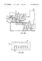
- FIG. 1is a view in elevation of an imaging apparatus adapted to sense the consumables loaded therein, the imaging apparatus including a communications link;
- FIG. 2is a view in elevation of a photoprocessing device belonging to the imaging apparatus
- FIG. 3Ais a view in elevation of an alternate embodiment of the photoprocessing device
- FIG. 3Billustrates a control console belonging to the invention
- FIG. 4illustrates an alternative embodiment of the imaging apparatus including the communications link, wherein the photoprocessing device belonging to the imaging apparatus is an inkjet printer;
- FIG. 5illustrates still another alternative embodiment of the imaging apparatus including the communications link, wherein the photoprocessing device belonging to the imaging apparatus is a thermal dye printer;
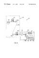
- FIG. 6illustrates an alternative embodiment of the imaging apparatus including the communications link, wherein the photoprocessing device belonging to the imaging apparatus is an electrophotographic printer.
- an imaging apparatusgenerally referred to as 10 , adapted to sense type of an imaging consumable loaded therein.
- the imaging consumablemay be, for example, a photosensitive paper consumable, a developer consumable, a bleach consumable, a fixer consumable, an ink consumable, an electrophotographic toner consumable, an inkjet media consumable, a thermal dye donor web consumable, a thermal dye media consumable, a laminate consumable, an inkjet printhead cleaning fluid consumable or a film consumable.
- imaging apparatus 10includes an image forming assembly, such as a photoprocessing device 20 , which may be a minilab.
- Photoprocessing device 20may be an inkjet printer, a thermal dye printer, a photographic printer, an electrophotographic printer, or the like.
- the imaging consumablesare illustrated as a photosensitive paper 25 and prepackaged chemicals 27 a/b/c .
- prepackaged chemicals 27 a/b/cmay be, for example, “KODAK EKTACOLOR SM CHEMICALS” available from the Eastman Kodak Company located in Rochester, N.Y.
- Each of the prepackaged chemicals 27 a/b/cis provided in an individual package capable of being loaded into photoprocessing device 20 .
- photoprocessing device 20includes an RF (Radio Frequency) transceiver 30 for reasons disclosed hereinbelow.
- Transceiver 30may be a “Model S2000” transceiver available from Texas Instruments, Incorporated, located in Dallas, Tex.
- transceiver 30may be a “Model U2270B” transceiver available from Vishay-Telefunken Semiconductors, Incorporated, located in Malvern, PA.
- transceiver 30is connected, by means of a multiplexing switch 40 , to a plurality of antennae 50 a/b/c/d/e respectively assigned to each of a plurality of the consumables 25 and 27 a/b/c , as shown.
- transceiver 30serves as an electromagnetic “reader” and is capable of transmitting a first electromagnetic field 55 of a first predetermined radio frequency.
- Transceiver 30is also capable of receiving a second electromagnetic field 56 of a second predetermined radio frequency. Typically, the same frequency serves for both the first and second electromagnetic fields 55 and 56 .
- each of the transponders 60 a/b/c/d/emay be an “SAMPT” (Selective Addressable Multi-Page Transponder), Part Number “RI-TRP-IR2B” available from Texas Instruments, Incorporated.
- SAMPTSelective Addressable Multi-Page Transponder
- RI-TRP-IR2BPart Number “RI-TRP-IR2B” available from Texas Instruments, Incorporated.
- each of the transponders 60 a/b/c/d/emay be a “Model TL5550” transponder available from Vishay-Telefunken Semiconductors, Incorporated.
- RF transponders 60 a/b/c/d/eare preferably relatively low-power transponders deriving their power from the first electromagnetic field 55 emitted by antennae 50 a/b/c/d/e . This allows transponders 60 a/b/c/d/e to be compact and small for reducing size of photoprocessing device 20 .
- transponders 60 a/b/c/d/eare generally cylindrical, smaller than 4 mm in diameter and less than 32 mm in length. As described in detail hereinbelow, transponders 60 a/b/c/d/e serve as identifiers for characterizing type of consumable loaded into photoprocessing device 20 .
- transceiver 30communicates, by means of antennae 50 a/b/c/d/e , with each of transponders 60 a/b/c/d/e .
- Transceiver 30polls a single transponder 60 a/b/c/d/e at a time using any of a number of possible multiplexing schemes known in the art.
- multiplexing switch 40using techniques and components well-known in the art, makes an electrical connection between a specific antenna 50 a , 50 b , 50 c , 50 d or 50 e and transceiver 50 in order to respectively poll a specific transponder 60 a , 60 b , 60 c , 60 d or 60 e .
- Alternate mechanisms for polling individual transponders 60 a , 60 b , 60 c , 60 d or 60 einclude use of a plurality of microreader modules, such as a “RI-STU-MRD1 Micro-Reader” available from Texas Instruments, Inc. Using this scheme, such a microreader module, connected to a control logic processor 65 , would be disposed within apparatus 10 near the location of each transponder 54 . The function of such a processor 65 is disclosed in detail hereinbelow.
- Yet another alternative polling techniqueemploys a “non-collision” algorithm, whereby transceiver 30 successively communicates with multiple transponders 60 a , 60 b , 60 c , 60 d or 60 e using a sequence of increasing signal strengths and using the capability of transceiver 30 to selectively address and communicate with each transponder 60 a , 60 b , 60 c , 60 d or 60 e , and then to selectively disable each transponder 60 a , 60 b , 60 c , 60 d or 60 e individually.
- Such a systemcould require fewer antennae than transponders; provided, however, that the range is sufficient to encompass multiple transponders. Since the transponder has a unique identification, it is possible that only one antenna would be required. This would reduce hardware cost of the system.
- transceiver 30is electrically coupled to the previously mentioned control logic processor 65 by means of a standard interface, such as a RS-232C serial connection.
- a standard interfacesuch as a RS-232C serial connection.
- This connectionin conjunction with the polling technique described hereinabove, allows control logic processor 65 to control operation of transceiver 30 so that transceiver 30 can selectively and successively poll individual transponders 60 a , 60 b , 60 c , 60 d and 60 e in order to access consumable identifying information from each transponder 60 a , 60 b , 60 c , 60 d or 60 e .
- transponders 60 a , 60 b , 60 c , 60 d and 60 ecorrespond to respective ones of consumables 27 and 27 a/b/c/e loaded in photoprocessing device 20 .
- control logic processor 65uses an instruction program for controlling timing of the processing sequence of photoprocessing device 20 .
- the instruction programmay operate using a number of variables, such as exposure time.
- a default value of exposure timeis used for processing in the prior art; however, it is known that exposure time can be variable depending on the type of photosensitive paper being printed upon (for example, glossy or matte finish paper).
- the inventionincludes a memory register in control logic processor 65 that can be written with an alternate exposure time value, based on type of photosensitive paper loaded into photoprocessing device 20 .
- the variable usedcan be exposure time, other suitable variables may also be used, if desired.
- FIGS. 3A and 3Bthere is shown an alternate embodiment of the present invention for automated sensing of type of consumables 25 and 27 a/b/c/ and identification of the manufactured batch associated with each consumable.
- a plurality of readerssuch as optical bar code readers 70 a/b/c/d/e , are disposed within photoprocessing device 20 to optically read respective ones of a plurality of indicia, such as bar codes 75 a/b/c/d/e .
- the bar codes 75 a/b/c/d/eare preferably affixed to respective ones of consumables 25 and 27 a/b/c .
- Bar codes 75 a/b/c/d/efunction as identifiers for characterizing type of consumable 25 and 27 a/b/c loaded into photoprocessing device 20 .
- a single bar code readermay be used for scanning of the consumable by the operator prior to loading the consumable in photoprocessing device 20 .
- the indiciamay be magnetic strips provided on consumables 25 and 27 a/b/c (for example, on the consumables packaging).
- readers 70 a/b/c/d/eare magnetic strip readers disposed in photoprocessing device 20 , which readers 70 a/b/c/d/e are capable of reading one or more of the magnetic strips.
- the indiciamay be embedded trace patterns readable by suitable readers available in the art.
- Control console 80may include a plurality of input keys 83 for operator input of the information.
- Control console 80may also include a display panel 85 for displaying the information input by the operator.
- operator errormay occur while the operator enters the identifier information. Therefore, automating reading of consumable and batch identifier information is preferred in order to avoid operator error.
- an initial identification sequencetakes place.
- transponders 60 a/b/c/d/e on the newly loaded consumableare initially read and its identifier information stored by control processor 65 .
- This sequencecan be operator-initiated, such as by manual entry of an appropriate command through control console 80 .
- consumable initializationcan be initiated by sensing a mechanical event, such as closing of a door panel during loading of the consumable into photoprocessing device 20 or mechanical detection of presence of the consumable while residing in device 20 .
- imaging apparatus 10comprises a remote network access, generally referred to as 85 .
- Network access 85includes a telecommunications link 90 for reasons disclosed hereinbelow.
- photoprocessing device 20is connected to an intermediary networked server 100 that communicates with control logic processor 65 over a standard interface, such as a RS 232C serial connection.
- Networked server 100may be any of a number of standard computer platforms known in the art, such as a personal computer (as shown) configured for Internet connection.
- Telecommunications link 90may be any of a number of connections well known in the art.
- telecommunications link 90may be implemented using a standard Internet connection.
- telecommunications link 90may include a telephone line by which a first modem 105 a (modulator/demodulator 105 ) connects networked server 100 to the telephone line for Internet access.
- First modem 105 aitself may be a separate, free-standing device or integrally incorporated into networked server 100 .
- telecommunications link 90need not be a telephone line; rather, telecommunications link 90 may be formed of electromagnetic waves broadcast by networked server 100 at one or more predetermined radio frequencies.
- FIG. 1necessarily represents all possible implementations of Internet service connection.
- imaging apparatus 10further includes a host computer 110 coupled to telecommunications link 90 , such as by means of a second modem 105 b .
- Host computer 110may be located at the site of the consumables manufacturer or at the site of the manufacturer of photoprocessing device 20 and contains computer software logic and data access capabilities for accepting consumables identifier information from a remotely connected photoprocessing device 20 . Based on this identifier information, host computer 110 returns processing information to photoprocessing device 20 on the specific consumable loaded in photoprocessing device 20 .
- Host computer 110can be any of a number of workstation computer platforms, including but not limited to a suitably configured personal computer or UNIX-based workstation.
- host computer, 110is capable of accessing a consumables information data source 120 that contains detailed test and performance measurements and manufacturing data on each batch of consumable 25 and 27 a/b/c .
- Data source 120may be stored on host computer 110 or stored on a separate UNIX-based workstation (not shown) running suitable database management software, which software may be, for example, “ORACLE Database” software available from Oracle Corporation, located in Redwood Shores, Calif.
- networked access 85may include an Internet connection.
- a standard HTTP (Hypertext Transfer Protocol) controlis employed to provide 2-way communication between remote host computer 110 and networked server 100 .
- HTTPHypertext Transfer Protocol
- This configuration of the present inventionallows use of conventional “browser” utilities and user interfaces well-known in the telecommunications art.
- networked server 100is accessed by means of its assigned HTTP address. Download of data to networked server 100 in the form of a file is performed by remote host computer 110 using automated scripts, such as stored commands that run an FTP (File Transfer Protocol) session or, alternately, using a sequence of commands manually entered into host computer 110 .
- FTPFile Transfer Protocol
- Consumables image forming information that has been acquired by networked server 100is stored in memory as a file on networked server 100 .
- Data from remote host computer 110received by networked server 100 using the same network protocol arrangement, can then be transferred to control logic processor 65 for modifying process variables used in operation of photoprocessing device 20 .
- control logic processor 65controls image processing in photoprocessing device 20 .
- Image forming information obtained through telecommunications link 90 from remote host computer 110provides process variables used by a processing program running locally in control logic processor 65 .
- control logic processor 65makes the control decisions.
- An alternative control schemeemploys remote host computer 110 as a decision-making component.
- remote host computer 110provides operating instructions to control logic processor 65 so as to alter processing based on combination of consumables 25 and 27 a/b/c loaded in photoprocessor device 20 .
- This alternate schemeallows a measure of remote control of the imaging process running in photoprocessing device 20 .
- photoprocessing device 20may have the following exemplary consumables loaded therein:
- transceiver 30polls each transponder 60 a/b/c/d/e and obtains consumable type and batch number identifier information from each transponder 60 a/b/c/d/e .
- transponders 60 a/b/c/d/efunction as identifiers for characterizing type of consumables.
- transceiver 30functions as a reader for reading the identifier information of each transponder 60 a/b/c/d/e .
- control logic processor 65transfers this consumables identifier information over its serial link to networked server 100 .
- Networked server 100stores this consumables data in memory as a file.
- Transfer of the file of consumables identifier information from networked server 100can occur in a number of ways. For example, loading of a new consumable 25 , 27 a , 27 b , 27 c and/or 27 d can initiate network communication with remote host computer 110 by establishing an FTP session with remote host computer 110 . When the FTP session is established, networked server 100 transfers the consumables data file to remote host computer 110 .
- the memory mounted on each of consumables 25 and/or 27 a/b/cincludes specific network access data needed for addressing host computer 110 , such as the correct address, security passwords, and other data that fully automate access to the correct data at remote host computer 110 . Storage of the network access data in the memory mounted on the consumable eliminates need for operator interaction to input data and potential operator error in obtaining correct imaging forming information.
- remote host computer 110confirms the data received from control logic processor 65 that is sent by networked server 100 and responds by providing updated manufacturing data on each consumable 25 and 27 a/b/c loaded in photoprocessing device 20 .
- image forming information transferred from remote host computer 110 for a roll of photosensitive paper 25may be any of the exemplary data displayed in Table 1 hereinbelow.
- Sensito- 128 Parameter valuesallowing metric characterization of sensitometric Data response for this paper, including exposure/density reciprocity characteristics for each exposure source (such as optical, LED, laser) that could be used with this paper type.
- Exposito- 128 Parameter valuesallowing metric characterization of sensitometric Data response for this paper, including exposure/density reciprocity characteristics for each exposure source (such as optical, LED, laser) that could be used with this paper type.
- Networked server 100transfers the file data comprising image forming information to control logic processor 65 .
- Control logic processor 65then adjusts its processing operation based on the updated imaging forming information received from networked server 100 , such as by altering exposure time.
- host computerdefines the processing operation rather than control logic processor 65 .
- host computer 110analyzes the identifier information defined by the identifier mounted on loaded consumables 25 and/or 27 a/b/c and determines, using a control program that accesses and uses information stored in consumables data source 120 , that the combination of consumables 25 and 27 a/b/c loaded in photoprocessing device 20 work best together when developer speed in photoprocessing device 20 is increased by approximately 8 per cent.
- Remote host computer 110then transmits a file, through telecommunications link 90 , as a response message to networked server 100 , indicating in the file the recommendation to increase developer speed.
- Control logic processor 65then alters processing using this new operating instruction.
- an inkjet printer 130is connected to networked access 85 for remote communication with host computer 110 .
- control logic processor 65 in printer 130senses identity of an ink consumable 135 a , 135 b , 135 c and/or 135 d loaded in printer 130 and also senses identity of an inkjet media consumable 140 .
- Control logic processor 65reports this identifier information by means of telecommunications link 90 to host computer 110 .
- Host computer 110returns image forming information to printer 130 for optimizing use of consumables 135 a/b/c/d and 140 loaded in printer 130 .
- up-to-date sensitometric data from the manufacturer of consumable 135 cwhich may be a yellow ink consumable, could be used to indicate need to increase ink dot size to boost density in highlight regions of an output image.
- photoprocessing device 20may alternatively be a thermal dye printer 150 .
- Thermal dye printer 150creates an image onto a sheet of receiver media 160 residing in a receiver tray 170 .
- Thermal dye printer 150creates the image by transferring dye from a dye donor ribbon consumable 180 onto receiver 160 .
- Ribbon consumable 180is illustrated wound about a supply spool 185 a and a take-up spool 185 b .
- a dye donor patch(not shown) of a particular color (typically cyan, magenta, yellow, or black) on ribbon consumable 180 is placed against receiver media 160 .
- printhead 190heats the donor patch as the donor patch is moved into the path of printhead 190 .
- printhead 190may comprise a plurality of thermal resistive heating elements (not shown) or a laser source (also not shown). This heating action causes localized transfer of dye colorant from the donor ribbon patch to receiver media 160 in a pattern that creates the printed image. The amount of exposure energy applied controls how much dye is transferred, which determines color density of the image.
- An exemplary thermal dye printeris the “KODAK XLS 8600 PS Color Printer” available from the Eastman Kodak Company located in Rochester, N.Y.
- transceiver 30is present in thermal dye printer 150 together with a transponder 210 coupled to either of donor ribbon spools 185 a/b .
- Transceiver 30 and transponder 210cooperatively function in a manner as previously described.
- photoprocessing device 20may alternatively be an electrophotographic printer 210 comprising an image forming assembly 220 , which is an electrophotographic printhead, capable of forming an image on sheets of receiver media 160 residing in tray 170 .
- printer 210Disposed in printer 210 are a plurality of toner cartridge consumables 230 a/b/c/d having toner therein. Coupled to each toner cartridge consumable 230 a/b/c/d is a transponder 240 a/b/c/d , respectively.
- Transceiver 30 and transponders 240 a/b/c/dcooperatively function in a manner as previously described.
- An advantage of the present inventionsis that use thereof avoids manual data entry and its concomitant operator errors. This is so because the invention allows automatic reading of consumable identifier information and transmission of that identifier information to a data source containing corresponding image forming information which is then returned to the photoprocessing device (or printer). This up-to-date image forming information is then used to produce quality images.
- Another advantage of the present inventionis that it provides information on consumables usage that persists even when the consumable is temporarily removed from the imaging apparatus, which may occur, for example, when quantity of consumable is insufficient to satisfy a large production run.
- memory data, variable exposure time and quantity usedcan be stored directly with the consumable itself.
- a consumableis removed from photoprocessing device 20
- its variablesremain stored in non-volatile memory so that these same variables are applied to the photoprocessing sequencing when the consumable is reinserted into photoprocessing device 20 .
- the consumable previously removed from the imaging apparatusis reinserted into the imaging apparatus, which automatically identifies the consumable, the exposure time and the quantity of it that remains.
- This aspect of the inventionobtains predictive process information that allows photofinishing and printer optimization with a corresponding decrease in wasted consumable because the consumable removed from the imaging apparatus is not discarded, but rather salvaged. Of course, this result obtains gains in image quality and customer satisfaction.
- Yet another advantage of the present inventionis that use thereof allows consumables manufacturers to provide their customers with updated imaging information regarding consumables performance after the consumable is manufactured and shipped.
- Still another advantage of the present inventionis that use thereof predicts interaction results beforehand and adapts operation of the photoprocessing device to consumables loaded therein. That is, earlier techniques for remote management of photoprocessing apparatus respond to process results chiefly by processing control strips and reporting measurements obtained after processing.
- the present inventionby providing imaging information on the consumables loaded in the photoprocessing device, predicts interaction results beforehand, and thereby adapts the operation of photoprocessing device 20 to its consumables, based on information obtained from the consumables manufacturer. In doing so, the present invention offers advantages of increased efficiency, more pleasing printed images, and reduced waste. These advantages apply not only to a photoprocessing device, but also for other imaging apparatus.
- the present inventionprovides these and other advantages without requiring redesign of consumables packaging and without requiring retrofit of existing apparatus for customers which is particularly important to customers who may not yet be ready to make an additional capital investment.
- a number of alternate methods for automated sensing and reporting of consumable type and batch identificationcan be used, including a memory mounted on the consumable and also requiring electrical contact for sensing consumable identifier information stored in memory.
- a networking arrangementmay be used in combination with a plurality of high-volume photoprocessing systems as well as with digital printers. Such a networking arrangement would allow access to more than one remote host computer, so that the photoprocessing device can obtain imaging forming information about consumables that have been supplied from different manufactures.
- an operatorcan be given the option to decide whether or not to use operating instructions downloaded to memory on the control logic processor (or downloaded to memory mounted on the consumable itself) from the remote host. This can include the capability to restore original or default operating parameters to memory, or to prevent writing new data to memory mounted on the consumable, if operating instructions obtained from remote host computer 110 were to result in unsatisfactory operation.
- the operatorcan also be given control over the timing of data transfer through the telecommunications link, delaying or deferring network access, until a more convenient time, as well as operating using current or default operating values.
- type of network connectioncan vary widely from that disclosed above. That is, the interconnection scheme could alternately use, for example, a local area network, dedicated phone lines, or any other suitable network mechanism. Transmission means could include not only hardwired telecommunications lines but also satellite links.
- the file transfer method and protocolcan take any one of a number of variations. That is, the control logic processor may itself be configured with a network address and with the necessary connection hardware and software by providing an Ethernet controller and configuring the controller with an IP address and network connection. This would eliminate need for an intermediary networked server.
Landscapes
- Physics & Mathematics (AREA)
- General Physics & Mathematics (AREA)
- Engineering & Computer Science (AREA)
- Microelectronics & Electronic Packaging (AREA)
- Accessory Devices And Overall Control Thereof (AREA)
- Control Or Security For Electrophotography (AREA)
- Photographic Processing Devices Using Wet Methods (AREA)
- Projection-Type Copiers In General (AREA)
- Facsimiles In General (AREA)
Abstract
Description
| TABLE 1 |
| Data Provided for Roll of |
| Number | ||||
| of | ||||
| Data Stored | Bits | Description | ||
| Consumable | 8 | An 8-bit number encoding the type of | ||
| Type | consumable. | |||
| Product | ||||
| 40 | 10-digit product code. (May not be | |||
| Code | required if Consumable Type Identifier | |||
| provides enough data.) | ||||
| Catalog | 32 | For example, TG 4745. | ||
| Number | ||||
| Manufacture | 16 | 16-bit encoded date. Includes 4-bit | ||
| Date | month, 5-bit day, 7-bit year components. | |||
| Batch | 128 | Includes encoded batch number, | ||
| Emulsion | sensitivity and response data from | |||
| Data | testing of samples, density benchmark | |||
| data, sensitometry data obtained for the | ||||
| batch. | ||||
| Sensito- | 128 | Parameter values allowing | ||
| metric | characterization of sensitometric | |||
| Data | response for this paper, including | |||
| exposure/density reciprocity | ||||
| characteristics for each exposure source | ||||
| (such as optical, LED, laser) that could | ||||
| be used with this paper type. | ||||
| Roll length | 16 | 16-bit encoded data on length of roll of | ||
| Roll width | 16 | 16-bit encoded data on width of roll of | ||
Claims (38)
Priority Applications (3)
| Application Number | Priority Date | Filing Date | Title |
|---|---|---|---|
| US09/334,021US6644544B1 (en) | 1999-06-16 | 1999-06-16 | Imaging apparatus capable of forming an image consistent with type of imaging consumable loaded therein and method of assembling the apparatus |
| EP00201974AEP1061409A1 (en) | 1999-06-16 | 2000-06-05 | Imaging apparatus |
| JP2000181642AJP2001080177A (en) | 1999-06-16 | 2000-06-16 | Imaging apparatus having function for forming image suitable to form of loaded consumable goods for imaging and method for constituting imaging apparatus |
Applications Claiming Priority (1)
| Application Number | Priority Date | Filing Date | Title |
|---|---|---|---|
| US09/334,021US6644544B1 (en) | 1999-06-16 | 1999-06-16 | Imaging apparatus capable of forming an image consistent with type of imaging consumable loaded therein and method of assembling the apparatus |
Publications (1)
| Publication Number | Publication Date |
|---|---|
| US6644544B1true US6644544B1 (en) | 2003-11-11 |
Family
ID=23305226
Family Applications (1)
| Application Number | Title | Priority Date | Filing Date |
|---|---|---|---|
| US09/334,021Expired - Fee RelatedUS6644544B1 (en) | 1999-06-16 | 1999-06-16 | Imaging apparatus capable of forming an image consistent with type of imaging consumable loaded therein and method of assembling the apparatus |
Country Status (3)
| Country | Link |
|---|---|
| US (1) | US6644544B1 (en) |
| EP (1) | EP1061409A1 (en) |
| JP (1) | JP2001080177A (en) |
Cited By (12)
| Publication number | Priority date | Publication date | Assignee | Title |
|---|---|---|---|---|
| US20030135431A1 (en)* | 2001-12-20 | 2003-07-17 | Nexpress Solutions Llc | Linking ORC life tracking/usage with inventory management |
| US20030200160A1 (en)* | 2000-03-07 | 2003-10-23 | Seiko Epson Corporation | Method for replenishing consumables and system for managing the replenishment of consumables |
| US20040178267A1 (en)* | 2003-03-11 | 2004-09-16 | Zebra Technologies Corporation | System and Method for Selective Communication with RFID Transponders |
| US6885472B1 (en)* | 1999-08-24 | 2005-04-26 | Canon Kabushiki Kaisha | Printing system, printing apparatus, information processing apparatus, control method therefor, and computer-readable memory |
| US20080298822A1 (en)* | 2007-05-30 | 2008-12-04 | Zih Corp. | System for processing media units and an associated media roll |
| US20090162123A1 (en)* | 2007-12-19 | 2009-06-25 | Zih Corp. | Platen incorporating an rfid coupling device |
| US7664257B2 (en) | 2001-08-24 | 2010-02-16 | Zih Corp. | Method and apparatus for article authentication |
| US20100197474A1 (en)* | 2009-02-03 | 2010-08-05 | Girnet Internacional, S.L. | Machine for the manufacture of bags |
| USRE44220E1 (en) | 1998-06-18 | 2013-05-14 | Zih Corp. | Electronic identification system and method with source authenticity |
| US8721203B2 (en) | 2005-10-06 | 2014-05-13 | Zih Corp. | Memory system and method for consumables of a printer |
| US8952784B2 (en) | 2012-05-23 | 2015-02-10 | Eastman Kodak Company | Verifying identification of sequentially supplied fluids |
| US9296214B2 (en) | 2004-07-02 | 2016-03-29 | Zih Corp. | Thermal print head usage monitor and method for using the monitor |
Families Citing this family (6)
| Publication number | Priority date | Publication date | Assignee | Title |
|---|---|---|---|---|
| US7387253B1 (en) | 1996-09-03 | 2008-06-17 | Hand Held Products, Inc. | Optical reader system comprising local host processor and optical reader |
| EP1160619A3 (en)* | 2000-06-02 | 2002-04-17 | Eastman Kodak Company | Transmitting process parameters for imaging |
| US7099028B2 (en)* | 2001-07-20 | 2006-08-29 | Hewlett-Packard Development Company, L.P. | Systems and methods for providing restricted web site access to users of certain brands of printing device replaceable components |
| US20030080191A1 (en) | 2001-10-26 | 2003-05-01 | Allen Lubow | Method and apparatus for applying bar code information to products during production |
| EP1466297A4 (en) | 2001-12-17 | 2005-10-19 | Int Barcode Corp | Double-sided bar code doubling as a single bar code |
| KR100680748B1 (en)* | 2004-11-03 | 2007-02-08 | 삼성전자주식회사 | Wireless projector system |
Citations (52)
| Publication number | Priority date | Publication date | Assignee | Title |
|---|---|---|---|---|
| US4663625A (en) | 1983-11-30 | 1987-05-05 | Motion Magnetics Inc. | Passive tag identification system and method |
| US4742470A (en) | 1985-12-30 | 1988-05-03 | Gte Valeron Corporation | Tool identification system |
| US4806958A (en) | 1988-01-11 | 1989-02-21 | Eastman Kodak Company | Cassette/machine optically coupled interface |
| US5008661A (en) | 1985-09-27 | 1991-04-16 | Raj Phani K | Electronic remote chemical identification system |
| US5019815A (en) | 1979-10-12 | 1991-05-28 | Lemelson Jerome H | Radio frequency controlled interrogator-responder system with passive code generator |
| EP0443443A2 (en) | 1990-02-19 | 1991-08-28 | Fuji Photo Film Co., Ltd. | Remote management system for photographic equipment |
| US5049904A (en) | 1989-01-27 | 1991-09-17 | Shimadzu Corporation | Printer having identifiable interchangeable heads |
| US5049898A (en) | 1989-03-20 | 1991-09-17 | Hewlett-Packard Company | Printhead having memory element |
| US5078523A (en) | 1988-03-04 | 1992-01-07 | Varitronic Systems, Inc. | Tape cassette with identifying circuit element for printing machine |
| US5104247A (en) | 1989-07-18 | 1992-04-14 | Canon Kabushiki Kaisha | Recording control method, recording method, and recording apparatus for multicolor ink ribbon |
| US5105190A (en) | 1986-04-22 | 1992-04-14 | N.V. Nederlandsche Apparatenfabriek Nedap | Electromagnetic identification system |
| EP0509520A2 (en) | 1991-04-18 | 1992-10-21 | X-Rite, Inc. | Apparatus and method for color measurement network message log structure |
| US5184152A (en) | 1990-12-04 | 1993-02-02 | Sumimoto Electric Interconnect Products, Inc. | Printing apparatus and method for printing on an elongated member such as a tube |
| US5185315A (en) | 1991-02-21 | 1993-02-09 | Eastman Kodak Company | Making encoded dye-donor films for thermal printers |
| US5196862A (en) | 1992-02-21 | 1993-03-23 | Eastman Kodak Company | Apparatus and method for donor sensing at the print line in a thermal printer |
| US5220352A (en)* | 1990-10-29 | 1993-06-15 | Minolta Camera Kabushiki Kaisha | Thermal transfer recording device |
| US5224784A (en) | 1988-06-10 | 1993-07-06 | Ta Triumph-Adler | Electronically controlled typewriter, printer, or the like and ribbon cassette or type-wheel cassette therefor |
| US5266968A (en) | 1992-03-27 | 1993-11-30 | Eastman Kodak Company | Non-volatile memory thermal printer cartridge |
| US5268708A (en) | 1991-08-23 | 1993-12-07 | Eastman Kodak Company | Laser thermal printer with an automatic material supply |
| US5297881A (en) | 1991-05-16 | 1994-03-29 | Mitsubishi Steel Mfg. Co., Ltd. | Printing machine carriage having a magnetic encoder |
| US5305020A (en) | 1992-12-21 | 1994-04-19 | Tektronix, Inc. | Thermal transfer printer having media pre-coat selection apparatus and methods |
| US5318370A (en) | 1992-11-17 | 1994-06-07 | Varitronic Systems, Inc. | Cartridge with data memory system and method regarding same |
| US5331338A (en) | 1992-01-30 | 1994-07-19 | Printware, Inc. | Web steering for an image recorder |
| US5342671A (en) | 1992-06-05 | 1994-08-30 | Eastman Kodak Company | Encoded dye receiver |
| US5343276A (en) | 1992-05-27 | 1994-08-30 | Mita Industrial Co., Ltd. | Management system of image forming apparatuses |
| US5365312A (en) | 1988-07-25 | 1994-11-15 | Mannesmann Ag | Arrangement for printer equipment for monitoring reservoirs that contain printing medium |
| US5430441A (en) | 1993-10-12 | 1995-07-04 | Motorola, Inc. | Transponding tag and method |
| US5455617A (en) | 1992-03-27 | 1995-10-03 | Eastman Kodak Company | Thermal printer supply having non-volatile memory |
| US5491468A (en) | 1993-06-24 | 1996-02-13 | Westinghouse Electric Corporation | Identification system and method with passive tag |
| US5491327A (en) | 1994-08-10 | 1996-02-13 | American Magnetics Corporation | Universal magnetic medium encoder with tilt-compensating apparatus |
| US5493385A (en) | 1994-12-09 | 1996-02-20 | Eastman Kodak Company | Electrophotographic color printer apparatus and method with improved registration of colors |
| US5504507A (en) | 1992-10-08 | 1996-04-02 | Xerox Corporation | Electronically readable performance data on a thermal ink jet printhead chip |
| US5513920A (en) | 1992-10-29 | 1996-05-07 | Eastman Kodak Company | Dye donor web loading apparatus for a thermal printer |
| US5517282A (en) | 1992-05-27 | 1996-05-14 | Mita Industrial Co., Ltd. | Management system of image forming apparatuses |
| US5565906A (en) | 1994-01-13 | 1996-10-15 | Schoonscan, Inc. | Clocking means for bandwise imaging device |
| US5598201A (en) | 1994-01-31 | 1997-01-28 | Hewlett-Packard Company | Dual-resolution encoding system for high cyclic accuracy of print-medium advance in an inkjet printer |
| US5600352A (en) | 1994-06-27 | 1997-02-04 | Tektronix, Inc. | Apparatus and method for controlling coalescence of ink drops on a print medium |
| US5600350A (en) | 1993-04-30 | 1997-02-04 | Hewlett-Packard Company | Multiple inkjet print cartridge alignment by scanning a reference pattern and sampling same with reference to a position encoder |
| US5610635A (en) | 1994-08-09 | 1997-03-11 | Encad, Inc. | Printer ink cartridge with memory storage capacity |
| US5620265A (en) | 1993-12-28 | 1997-04-15 | Sony Corporation | Ink ribbon cartridge |
| US5634144A (en) | 1993-02-23 | 1997-05-27 | Eastman Kodak Company | Light beam communication method and system for linking a camera and a computer |
| US5647679A (en) | 1996-04-01 | 1997-07-15 | Itw Limited | Printer for printing on a continuous print medium |
| US5661515A (en) | 1993-01-22 | 1997-08-26 | Gerber Scientific Products, Inc. | Printer with feed fault detection |
| US5713288A (en) | 1995-08-03 | 1998-02-03 | Frazzitta; Joseph R. | Method and apparatus for use in offset printing |
| US5757394A (en) | 1995-09-27 | 1998-05-26 | Lexmark International, Inc. | Ink jet print head identification circuit with programmed transistor array |
| US5755519A (en) | 1996-12-04 | 1998-05-26 | Fargo Electronics, Inc. | Printer ribbon identification sensor |
| US5774639A (en) | 1995-02-17 | 1998-06-30 | Eastman Kodak Company | Printer media including compressed sensitometry curve information |
| US5812156A (en) | 1997-01-21 | 1998-09-22 | Hewlett-Packard Company | Apparatus controlled by data from consumable parts with incorporated memory devices |
| EP0873873A2 (en) | 1997-04-25 | 1998-10-28 | Hewlett-Packard Company | Image forming and office automation device consumable with memory |
| US5835817A (en) | 1994-12-22 | 1998-11-10 | Hewlett Packard Company | Replaceable part with integral memory for usage, calibration and other data |
| WO1998052762A2 (en) | 1997-05-20 | 1998-11-26 | Encad, Inc. | Intelligent printer components and printing system |
| US5860363A (en) | 1997-01-21 | 1999-01-19 | Hewlett-Packard Company | Ink jet cartridge with separately replaceable ink reservoir |
Family Cites Families (1)
| Publication number | Priority date | Publication date | Assignee | Title |
|---|---|---|---|---|
| JP3263248B2 (en)* | 1994-07-29 | 2002-03-04 | キヤノン株式会社 | Printing apparatus and printing method |
- 1999
- 1999-06-16USUS09/334,021patent/US6644544B1/ennot_activeExpired - Fee Related
- 2000
- 2000-06-05EPEP00201974Apatent/EP1061409A1/ennot_activeCeased
- 2000-06-16JPJP2000181642Apatent/JP2001080177A/enactivePending
Patent Citations (56)
| Publication number | Priority date | Publication date | Assignee | Title |
|---|---|---|---|---|
| US5019815A (en) | 1979-10-12 | 1991-05-28 | Lemelson Jerome H | Radio frequency controlled interrogator-responder system with passive code generator |
| US4663625A (en) | 1983-11-30 | 1987-05-05 | Motion Magnetics Inc. | Passive tag identification system and method |
| US5008661A (en) | 1985-09-27 | 1991-04-16 | Raj Phani K | Electronic remote chemical identification system |
| US4742470A (en) | 1985-12-30 | 1988-05-03 | Gte Valeron Corporation | Tool identification system |
| US5105190A (en) | 1986-04-22 | 1992-04-14 | N.V. Nederlandsche Apparatenfabriek Nedap | Electromagnetic identification system |
| US4806958A (en) | 1988-01-11 | 1989-02-21 | Eastman Kodak Company | Cassette/machine optically coupled interface |
| US5078523A (en) | 1988-03-04 | 1992-01-07 | Varitronic Systems, Inc. | Tape cassette with identifying circuit element for printing machine |
| US5224784A (en) | 1988-06-10 | 1993-07-06 | Ta Triumph-Adler | Electronically controlled typewriter, printer, or the like and ribbon cassette or type-wheel cassette therefor |
| US5365312A (en) | 1988-07-25 | 1994-11-15 | Mannesmann Ag | Arrangement for printer equipment for monitoring reservoirs that contain printing medium |
| US5049904A (en) | 1989-01-27 | 1991-09-17 | Shimadzu Corporation | Printer having identifiable interchangeable heads |
| US5049898A (en) | 1989-03-20 | 1991-09-17 | Hewlett-Packard Company | Printhead having memory element |
| US5104247A (en) | 1989-07-18 | 1992-04-14 | Canon Kabushiki Kaisha | Recording control method, recording method, and recording apparatus for multicolor ink ribbon |
| US5291420A (en) | 1990-02-19 | 1994-03-01 | Fugi Photo Film Co., Ltd. | Remote management system for photographic equipment |
| EP0443443A2 (en) | 1990-02-19 | 1991-08-28 | Fuji Photo Film Co., Ltd. | Remote management system for photographic equipment |
| US5220352A (en)* | 1990-10-29 | 1993-06-15 | Minolta Camera Kabushiki Kaisha | Thermal transfer recording device |
| US5184152A (en) | 1990-12-04 | 1993-02-02 | Sumimoto Electric Interconnect Products, Inc. | Printing apparatus and method for printing on an elongated member such as a tube |
| US5185315A (en) | 1991-02-21 | 1993-02-09 | Eastman Kodak Company | Making encoded dye-donor films for thermal printers |
| US5402361A (en) | 1991-04-18 | 1995-03-28 | X-Rite, Incorporated | Apparatus for method for logging, storing, and redirection of process related non-densitometric data generated by color processing equipment for use by an off site host computer |
| EP0509520A2 (en) | 1991-04-18 | 1992-10-21 | X-Rite, Inc. | Apparatus and method for color measurement network message log structure |
| US5297881A (en) | 1991-05-16 | 1994-03-29 | Mitsubishi Steel Mfg. Co., Ltd. | Printing machine carriage having a magnetic encoder |
| US5268708A (en) | 1991-08-23 | 1993-12-07 | Eastman Kodak Company | Laser thermal printer with an automatic material supply |
| US5331338A (en) | 1992-01-30 | 1994-07-19 | Printware, Inc. | Web steering for an image recorder |
| US5196862A (en) | 1992-02-21 | 1993-03-23 | Eastman Kodak Company | Apparatus and method for donor sensing at the print line in a thermal printer |
| US5266968A (en) | 1992-03-27 | 1993-11-30 | Eastman Kodak Company | Non-volatile memory thermal printer cartridge |
| US5455617A (en) | 1992-03-27 | 1995-10-03 | Eastman Kodak Company | Thermal printer supply having non-volatile memory |
| US5517282A (en) | 1992-05-27 | 1996-05-14 | Mita Industrial Co., Ltd. | Management system of image forming apparatuses |
| US5343276A (en) | 1992-05-27 | 1994-08-30 | Mita Industrial Co., Ltd. | Management system of image forming apparatuses |
| US5426011A (en) | 1992-06-05 | 1995-06-20 | Eastman Kodak Company | Thermal printing process with an encoded dye receiver having a transparent magnetic layer |
| US5342671A (en) | 1992-06-05 | 1994-08-30 | Eastman Kodak Company | Encoded dye receiver |
| US5504507A (en) | 1992-10-08 | 1996-04-02 | Xerox Corporation | Electronically readable performance data on a thermal ink jet printhead chip |
| US5562352A (en) | 1992-10-29 | 1996-10-08 | Eastman Kodak Company | Dye donor web loading apparatus for a thermal printer |
| US5513920A (en) | 1992-10-29 | 1996-05-07 | Eastman Kodak Company | Dye donor web loading apparatus for a thermal printer |
| US5318370A (en) | 1992-11-17 | 1994-06-07 | Varitronic Systems, Inc. | Cartridge with data memory system and method regarding same |
| US5305020A (en) | 1992-12-21 | 1994-04-19 | Tektronix, Inc. | Thermal transfer printer having media pre-coat selection apparatus and methods |
| US5661515A (en) | 1993-01-22 | 1997-08-26 | Gerber Scientific Products, Inc. | Printer with feed fault detection |
| US5634144A (en) | 1993-02-23 | 1997-05-27 | Eastman Kodak Company | Light beam communication method and system for linking a camera and a computer |
| US5600350A (en) | 1993-04-30 | 1997-02-04 | Hewlett-Packard Company | Multiple inkjet print cartridge alignment by scanning a reference pattern and sampling same with reference to a position encoder |
| US5491468A (en) | 1993-06-24 | 1996-02-13 | Westinghouse Electric Corporation | Identification system and method with passive tag |
| US5430441A (en) | 1993-10-12 | 1995-07-04 | Motorola, Inc. | Transponding tag and method |
| US5620265A (en) | 1993-12-28 | 1997-04-15 | Sony Corporation | Ink ribbon cartridge |
| US5565906A (en) | 1994-01-13 | 1996-10-15 | Schoonscan, Inc. | Clocking means for bandwise imaging device |
| US5598201A (en) | 1994-01-31 | 1997-01-28 | Hewlett-Packard Company | Dual-resolution encoding system for high cyclic accuracy of print-medium advance in an inkjet printer |
| US5600352A (en) | 1994-06-27 | 1997-02-04 | Tektronix, Inc. | Apparatus and method for controlling coalescence of ink drops on a print medium |
| US5610635A (en) | 1994-08-09 | 1997-03-11 | Encad, Inc. | Printer ink cartridge with memory storage capacity |
| US5491327A (en) | 1994-08-10 | 1996-02-13 | American Magnetics Corporation | Universal magnetic medium encoder with tilt-compensating apparatus |
| US5493385A (en) | 1994-12-09 | 1996-02-20 | Eastman Kodak Company | Electrophotographic color printer apparatus and method with improved registration of colors |
| US5835817A (en) | 1994-12-22 | 1998-11-10 | Hewlett Packard Company | Replaceable part with integral memory for usage, calibration and other data |
| US5774639A (en) | 1995-02-17 | 1998-06-30 | Eastman Kodak Company | Printer media including compressed sensitometry curve information |
| US5713288A (en) | 1995-08-03 | 1998-02-03 | Frazzitta; Joseph R. | Method and apparatus for use in offset printing |
| US5757394A (en) | 1995-09-27 | 1998-05-26 | Lexmark International, Inc. | Ink jet print head identification circuit with programmed transistor array |
| US5647679A (en) | 1996-04-01 | 1997-07-15 | Itw Limited | Printer for printing on a continuous print medium |
| US5755519A (en) | 1996-12-04 | 1998-05-26 | Fargo Electronics, Inc. | Printer ribbon identification sensor |
| US5812156A (en) | 1997-01-21 | 1998-09-22 | Hewlett-Packard Company | Apparatus controlled by data from consumable parts with incorporated memory devices |
| US5860363A (en) | 1997-01-21 | 1999-01-19 | Hewlett-Packard Company | Ink jet cartridge with separately replaceable ink reservoir |
| EP0873873A2 (en) | 1997-04-25 | 1998-10-28 | Hewlett-Packard Company | Image forming and office automation device consumable with memory |
| WO1998052762A2 (en) | 1997-05-20 | 1998-11-26 | Encad, Inc. | Intelligent printer components and printing system |
Non-Patent Citations (6)
| Title |
|---|
| TEMIC Semiconductors TK5550, Read/Write Transponder, Telefunken Semiconductors, Rev. A1, Apr. 30, 1997. |
| TEMIC Semicondutors e5550, Standard Read/Write Identification IC, Telefunken Semiconductors, Rev. A3, Mar. 17, 1998. |
| U.S. 09/133,114 titled: A Printer With Media Supply Spool Adapted To Sense Type Of Media, And Method Of Assembling Same, filed Aug. 12, 1998 in the name of Spurr et al. |
| U.S. 09/133,122 titled: A Printer Media Supply Spool Adapted To Allow The Printer To Sense Type Of Media, And Method Of Assembling Same, filed Aug. 12, 1998 in the name of Spurr et al. |
| U.S. 09/218,595 titled: A Printer With Donor And Receiver Media Supply Trays Each Adapted To Allow A Printer To Sense Type Of Media Therein, And Method Of Assembling The Printer And Trays, filed Dec. 22, 1998 in the name of Spurr et al. |
| U.S. 09/292,859 titled: A Photoprocessing Apparatus And Method Of Sensing Type Of Photoprocessing Consumable, filed Apr. 16, 1999 in the name of Spurr et al. |
Cited By (19)
| Publication number | Priority date | Publication date | Assignee | Title |
|---|---|---|---|---|
| USRE44220E1 (en) | 1998-06-18 | 2013-05-14 | Zih Corp. | Electronic identification system and method with source authenticity |
| US6885472B1 (en)* | 1999-08-24 | 2005-04-26 | Canon Kabushiki Kaisha | Printing system, printing apparatus, information processing apparatus, control method therefor, and computer-readable memory |
| US20030200160A1 (en)* | 2000-03-07 | 2003-10-23 | Seiko Epson Corporation | Method for replenishing consumables and system for managing the replenishment of consumables |
| US8667276B2 (en) | 2001-08-24 | 2014-03-04 | Zih Corp. | Method and apparatus for article authentication |
| US7664257B2 (en) | 2001-08-24 | 2010-02-16 | Zih Corp. | Method and apparatus for article authentication |
| US8301886B2 (en) | 2001-08-24 | 2012-10-30 | Zih Corp. | Method and apparatus for article authentication |
| US20030135431A1 (en)* | 2001-12-20 | 2003-07-17 | Nexpress Solutions Llc | Linking ORC life tracking/usage with inventory management |
| US20040178267A1 (en)* | 2003-03-11 | 2004-09-16 | Zebra Technologies Corporation | System and Method for Selective Communication with RFID Transponders |
| US6848616B2 (en)* | 2003-03-11 | 2005-02-01 | Zih Corp., A Delaware Corporation With Its Principal Office In Hamilton, Bermuda | System and method for selective communication with RFID transponders |
| US10315438B2 (en) | 2004-07-02 | 2019-06-11 | Zebra Technologies Corporation | Thermal print head usage monitor and method for using the monitor |
| US9296214B2 (en) | 2004-07-02 | 2016-03-29 | Zih Corp. | Thermal print head usage monitor and method for using the monitor |
| US8721203B2 (en) | 2005-10-06 | 2014-05-13 | Zih Corp. | Memory system and method for consumables of a printer |
| US9524460B2 (en) | 2007-05-30 | 2016-12-20 | Zih Corp. | System for processing media units and an associated media roll |
| US20080298822A1 (en)* | 2007-05-30 | 2008-12-04 | Zih Corp. | System for processing media units and an associated media roll |
| US20090162123A1 (en)* | 2007-12-19 | 2009-06-25 | Zih Corp. | Platen incorporating an rfid coupling device |
| US9415611B2 (en) | 2007-12-19 | 2016-08-16 | Zih Corp. | Platen incorporating an RFID coupling device |
| US8360946B2 (en)* | 2009-02-03 | 2013-01-29 | Girnet Internacional, S.L. | Machine for the manufacture of bags |
| US20100197474A1 (en)* | 2009-02-03 | 2010-08-05 | Girnet Internacional, S.L. | Machine for the manufacture of bags |
| US8952784B2 (en) | 2012-05-23 | 2015-02-10 | Eastman Kodak Company | Verifying identification of sequentially supplied fluids |
Also Published As
| Publication number | Publication date |
|---|---|
| EP1061409A1 (en) | 2000-12-20 |
| JP2001080177A (en) | 2001-03-27 |
Similar Documents
| Publication | Publication Date | Title |
|---|---|---|
| US6644544B1 (en) | Imaging apparatus capable of forming an image consistent with type of imaging consumable loaded therein and method of assembling the apparatus | |
| US6106166A (en) | Photoprocessing apparatus for sensing type of photoprocessing consumable and method of assembling the apparatus | |
| US6793307B2 (en) | Printer capable of forming an image on a receiver substrate according to type of receiver substrate and a method of assembling the printer | |
| US7221473B2 (en) | Printing system for updating printing characteristics with a printing consumable | |
| US6567622B2 (en) | Image forming devices and image forming methods | |
| US7426482B2 (en) | Image processing apparatus, method of placing order for expendables of image processing apparatus, storage medium, and program | |
| JP2001228760A (en) | Image forming apparatus and its control method, information processing apparatus and its control method, inventory management system, inventory management method, and memory medium | |
| EP1160619A2 (en) | Transmitting process parameters for imaging | |
| US20120069397A1 (en) | Transponder with memory for ink jet media | |
| US7729622B2 (en) | Image forming apparatus for displaying a message when a remaining amount of consumable becomes less | |
| JP2003043867A (en) | Diagnostic device, diagnostic method, image forming device, control method, storage medium, and program | |
| US7324232B2 (en) | Printer, printer setting method and corresponding program, and cartridge | |
| US9508046B2 (en) | Methods and systems for providing web content to a printing device | |
| JP2004240110A (en) | Printing equipment | |
| US20060268040A1 (en) | Image forming system, image forming apparatus and image forming method | |
| JP2004258186A (en) | Replacement and image forming apparatus | |
| JP2004054112A (en) | Image processing apparatus, method for ordering consumables for image processing apparatus, storage medium, and program | |
| JP2005148840A (en) | Server device and network system | |
| CN101155243A (en) | imaging device | |
| US7609403B2 (en) | Printing device with multiple recording agent cartridges and corresponding print management method | |
| JP2006072013A (en) | Information recording system | |
| JP2006065187A (en) | Consumables management system for photo processing equipment | |
| JP2000316020A (en) | Method for using server connected to network and server system | |
| JP2023152168A (en) | Image formation apparatus and control method | |
| JP2024172860A (en) | DEVICE, DEVICE CONTROL METHOD, AND PROGRAM - Patent application |
Legal Events
| Date | Code | Title | Description |
|---|---|---|---|
| AS | Assignment | Owner name:EASTMAN KODAK COMPANY, NEW YORK Free format text:;ASSIGNOR:SPURR, ROBERT W.;REEL/FRAME:010042/0113 Effective date:19990609 | |
| AS | Assignment | Owner name:EASTMAN KODAK COMPANY, NEW YORK Free format text:(ASSIGNMENT OF ASSIGNOR'S INTEREST) RE-RECORD TO CORRECT THE RECORDATION DATE OF 6/15/99 TO 6/16/99, PREVIOUSLY RECORDED AT REEL 010042, FRAME 0113.;ASSIGNOR:SPURR, ROBERT W.;REEL/FRAME:010318/0027 Effective date:19990609 | |
| FEPP | Fee payment procedure | Free format text:PAYOR NUMBER ASSIGNED (ORIGINAL EVENT CODE: ASPN); ENTITY STATUS OF PATENT OWNER: LARGE ENTITY | |
| FPAY | Fee payment | Year of fee payment:4 | |
| FPAY | Fee payment | Year of fee payment:8 | |
| AS | Assignment | Owner name:CITICORP NORTH AMERICA, INC., AS AGENT, NEW YORK Free format text:SECURITY INTEREST;ASSIGNORS:EASTMAN KODAK COMPANY;PAKON, INC.;REEL/FRAME:028201/0420 Effective date:20120215 | |
| AS | Assignment | Owner name:WILMINGTON TRUST, NATIONAL ASSOCIATION, AS AGENT, MINNESOTA Free format text:PATENT SECURITY AGREEMENT;ASSIGNORS:EASTMAN KODAK COMPANY;PAKON, INC.;REEL/FRAME:030122/0235 Effective date:20130322 Owner name:WILMINGTON TRUST, NATIONAL ASSOCIATION, AS AGENT, Free format text:PATENT SECURITY AGREEMENT;ASSIGNORS:EASTMAN KODAK COMPANY;PAKON, INC.;REEL/FRAME:030122/0235 Effective date:20130322 | |
| AS | Assignment | Owner name:BANK OF AMERICA N.A., AS AGENT, MASSACHUSETTS Free format text:INTELLECTUAL PROPERTY SECURITY AGREEMENT (ABL);ASSIGNORS:EASTMAN KODAK COMPANY;FAR EAST DEVELOPMENT LTD.;FPC INC.;AND OTHERS;REEL/FRAME:031162/0117 Effective date:20130903 Owner name:BARCLAYS BANK PLC, AS ADMINISTRATIVE AGENT, NEW YORK Free format text:INTELLECTUAL PROPERTY SECURITY AGREEMENT (SECOND LIEN);ASSIGNORS:EASTMAN KODAK COMPANY;FAR EAST DEVELOPMENT LTD.;FPC INC.;AND OTHERS;REEL/FRAME:031159/0001 Effective date:20130903 Owner name:JPMORGAN CHASE BANK, N.A., AS ADMINISTRATIVE, DELAWARE Free format text:INTELLECTUAL PROPERTY SECURITY AGREEMENT (FIRST LIEN);ASSIGNORS:EASTMAN KODAK COMPANY;FAR EAST DEVELOPMENT LTD.;FPC INC.;AND OTHERS;REEL/FRAME:031158/0001 Effective date:20130903 Owner name:EASTMAN KODAK COMPANY, NEW YORK Free format text:RELEASE OF SECURITY INTEREST IN PATENTS;ASSIGNORS:CITICORP NORTH AMERICA, INC., AS SENIOR DIP AGENT;WILMINGTON TRUST, NATIONAL ASSOCIATION, AS JUNIOR DIP AGENT;REEL/FRAME:031157/0451 Effective date:20130903 Owner name:PAKON, INC., NEW YORK Free format text:RELEASE OF SECURITY INTEREST IN PATENTS;ASSIGNORS:CITICORP NORTH AMERICA, INC., AS SENIOR DIP AGENT;WILMINGTON TRUST, NATIONAL ASSOCIATION, AS JUNIOR DIP AGENT;REEL/FRAME:031157/0451 Effective date:20130903 Owner name:JPMORGAN CHASE BANK, N.A., AS ADMINISTRATIVE, DELA Free format text:INTELLECTUAL PROPERTY SECURITY AGREEMENT (FIRST LIEN);ASSIGNORS:EASTMAN KODAK COMPANY;FAR EAST DEVELOPMENT LTD.;FPC INC.;AND OTHERS;REEL/FRAME:031158/0001 Effective date:20130903 Owner name:BARCLAYS BANK PLC, AS ADMINISTRATIVE AGENT, NEW YO Free format text:INTELLECTUAL PROPERTY SECURITY AGREEMENT (SECOND LIEN);ASSIGNORS:EASTMAN KODAK COMPANY;FAR EAST DEVELOPMENT LTD.;FPC INC.;AND OTHERS;REEL/FRAME:031159/0001 Effective date:20130903 | |
| REMI | Maintenance fee reminder mailed | ||
| LAPS | Lapse for failure to pay maintenance fees | ||
| STCH | Information on status: patent discontinuation | Free format text:PATENT EXPIRED DUE TO NONPAYMENT OF MAINTENANCE FEES UNDER 37 CFR 1.362 | |
| FP | Lapsed due to failure to pay maintenance fee | Effective date:20151111 | |
| AS | Assignment | Owner name:FAR EAST DEVELOPMENT LTD., NEW YORK Free format text:RELEASE BY SECURED PARTY;ASSIGNOR:JP MORGAN CHASE BANK, N.A., AS ADMINISTRATIVE AGENT;REEL/FRAME:049814/0001 Effective date:20190617 Owner name:QUALEX, INC., NEW YORK Free format text:RELEASE BY SECURED PARTY;ASSIGNOR:JP MORGAN CHASE BANK, N.A., AS ADMINISTRATIVE AGENT;REEL/FRAME:049814/0001 Effective date:20190617 Owner name:KODAK IMAGING NETWORK, INC., NEW YORK Free format text:RELEASE BY SECURED PARTY;ASSIGNOR:JP MORGAN CHASE BANK, N.A., AS ADMINISTRATIVE AGENT;REEL/FRAME:049814/0001 Effective date:20190617 Owner name:PAKON, INC., NEW YORK Free format text:RELEASE BY SECURED PARTY;ASSIGNOR:JP MORGAN CHASE BANK, N.A., AS ADMINISTRATIVE AGENT;REEL/FRAME:049814/0001 Effective date:20190617 Owner name:LASER PACIFIC MEDIA CORPORATION, NEW YORK Free format text:RELEASE BY SECURED PARTY;ASSIGNOR:JP MORGAN CHASE BANK, N.A., AS ADMINISTRATIVE AGENT;REEL/FRAME:049814/0001 Effective date:20190617 Owner name:EASTMAN KODAK COMPANY, NEW YORK Free format text:RELEASE BY SECURED PARTY;ASSIGNOR:JP MORGAN CHASE BANK, N.A., AS ADMINISTRATIVE AGENT;REEL/FRAME:049814/0001 Effective date:20190617 Owner name:KODAK PORTUGUESA LIMITED, NEW YORK Free format text:RELEASE BY SECURED PARTY;ASSIGNOR:JP MORGAN CHASE BANK, N.A., AS ADMINISTRATIVE AGENT;REEL/FRAME:049814/0001 Effective date:20190617 Owner name:KODAK AVIATION LEASING LLC, NEW YORK Free format text:RELEASE BY SECURED PARTY;ASSIGNOR:JP MORGAN CHASE BANK, N.A., AS ADMINISTRATIVE AGENT;REEL/FRAME:049814/0001 Effective date:20190617 Owner name:NPEC, INC., NEW YORK Free format text:RELEASE BY SECURED PARTY;ASSIGNOR:JP MORGAN CHASE BANK, N.A., AS ADMINISTRATIVE AGENT;REEL/FRAME:049814/0001 Effective date:20190617 Owner name:KODAK (NEAR EAST), INC., NEW YORK Free format text:RELEASE BY SECURED PARTY;ASSIGNOR:JP MORGAN CHASE BANK, N.A., AS ADMINISTRATIVE AGENT;REEL/FRAME:049814/0001 Effective date:20190617 Owner name:KODAK REALTY, INC., NEW YORK Free format text:RELEASE BY SECURED PARTY;ASSIGNOR:JP MORGAN CHASE BANK, N.A., AS ADMINISTRATIVE AGENT;REEL/FRAME:049814/0001 Effective date:20190617 Owner name:KODAK PHILIPPINES, LTD., NEW YORK Free format text:RELEASE BY SECURED PARTY;ASSIGNOR:JP MORGAN CHASE BANK, N.A., AS ADMINISTRATIVE AGENT;REEL/FRAME:049814/0001 Effective date:20190617 Owner name:KODAK AMERICAS, LTD., NEW YORK Free format text:RELEASE BY SECURED PARTY;ASSIGNOR:JP MORGAN CHASE BANK, N.A., AS ADMINISTRATIVE AGENT;REEL/FRAME:049814/0001 Effective date:20190617 Owner name:FPC, INC., NEW YORK Free format text:RELEASE BY SECURED PARTY;ASSIGNOR:JP MORGAN CHASE BANK, N.A., AS ADMINISTRATIVE AGENT;REEL/FRAME:049814/0001 Effective date:20190617 Owner name:CREO MANUFACTURING AMERICA LLC, NEW YORK Free format text:RELEASE BY SECURED PARTY;ASSIGNOR:JP MORGAN CHASE BANK, N.A., AS ADMINISTRATIVE AGENT;REEL/FRAME:049814/0001 Effective date:20190617 | |
| AS | Assignment | Owner name:KODAK AMERICAS LTD., NEW YORK Free format text:RELEASE BY SECURED PARTY;ASSIGNOR:BARCLAYS BANK PLC;REEL/FRAME:052773/0001 Effective date:20170202 Owner name:KODAK REALTY INC., NEW YORK Free format text:RELEASE BY SECURED PARTY;ASSIGNOR:BARCLAYS BANK PLC;REEL/FRAME:052773/0001 Effective date:20170202 Owner name:FAR EAST DEVELOPMENT LTD., NEW YORK Free format text:RELEASE BY SECURED PARTY;ASSIGNOR:BARCLAYS BANK PLC;REEL/FRAME:052773/0001 Effective date:20170202 Owner name:FPC INC., NEW YORK Free format text:RELEASE BY SECURED PARTY;ASSIGNOR:BARCLAYS BANK PLC;REEL/FRAME:052773/0001 Effective date:20170202 Owner name:KODAK (NEAR EAST) INC., NEW YORK Free format text:RELEASE BY SECURED PARTY;ASSIGNOR:BARCLAYS BANK PLC;REEL/FRAME:052773/0001 Effective date:20170202 Owner name:LASER PACIFIC MEDIA CORPORATION, NEW YORK Free format text:RELEASE BY SECURED PARTY;ASSIGNOR:BARCLAYS BANK PLC;REEL/FRAME:052773/0001 Effective date:20170202 Owner name:NPEC INC., NEW YORK Free format text:RELEASE BY SECURED PARTY;ASSIGNOR:BARCLAYS BANK PLC;REEL/FRAME:052773/0001 Effective date:20170202 Owner name:EASTMAN KODAK COMPANY, NEW YORK Free format text:RELEASE BY SECURED PARTY;ASSIGNOR:BARCLAYS BANK PLC;REEL/FRAME:052773/0001 Effective date:20170202 Owner name:QUALEX INC., NEW YORK Free format text:RELEASE BY SECURED PARTY;ASSIGNOR:BARCLAYS BANK PLC;REEL/FRAME:052773/0001 Effective date:20170202 Owner name:KODAK PHILIPPINES LTD., NEW YORK Free format text:RELEASE BY SECURED PARTY;ASSIGNOR:BARCLAYS BANK PLC;REEL/FRAME:052773/0001 Effective date:20170202 |