US6644481B2 - Apparatus and method for rackmounting a chassis - Google Patents
Apparatus and method for rackmounting a chassisDownload PDFInfo
- Publication number
- US6644481B2 US6644481B2US10/073,478US7347802AUS6644481B2US 6644481 B2US6644481 B2US 6644481B2US 7347802 AUS7347802 AUS 7347802AUS 6644481 B2US6644481 B2US 6644481B2
- Authority
- US
- United States
- Prior art keywords
- bracket
- rack
- mounting
- keyhole
- mounting shelf
- Prior art date
- Legal status (The legal status is an assumption and is not a legal conclusion. Google has not performed a legal analysis and makes no representation as to the accuracy of the status listed.)
- Expired - Lifetime
Links
Images


Classifications
- H—ELECTRICITY
- H05—ELECTRIC TECHNIQUES NOT OTHERWISE PROVIDED FOR
- H05K—PRINTED CIRCUITS; CASINGS OR CONSTRUCTIONAL DETAILS OF ELECTRIC APPARATUS; MANUFACTURE OF ASSEMBLAGES OF ELECTRICAL COMPONENTS
- H05K7/00—Constructional details common to different types of electric apparatus
- H05K7/14—Mounting supporting structure in casing or on frame or rack
- H05K7/1485—Servers; Data center rooms, e.g. 19-inch computer racks
- H05K7/1488—Cabinets therefor, e.g. chassis or racks or mechanical interfaces between blades and support structures
- H05K7/1489—Cabinets therefor, e.g. chassis or racks or mechanical interfaces between blades and support structures characterized by the mounting of blades therein, e.g. brackets, rails, trays
Definitions
- This inventionrelates in general to mounting devices, and in specific to an apparatus and method for rackmounting a chassis.
- Each rackcomprises several pieces of equipment or chassis.
- Each chassismay comprise a board that includes processors, memory, and/or power supplies.
- Other chassismight include telecommunications equipment, writing equipment, networking equipment, I/O equipment, and/or user interface equipment.
- the equipmentshould be removably mounted into the rack. This would allow the equipment to be easily serviced and/or installed.
- One way that the equipment can be removably attached to the rackis to use sliding rails that are attached to the workstation. The equipment or the chassis equipment may then be attached to the sliding rails.
- the chassisis supported by the sliding rails and can be moved into and out of the rack by the sliding rails, which slidably extend from the rack.
- the sliding railsmay incorporate ball bearings to more readily facilitate the sliding action.
- Another way that the chassis can be slidably mounted into the rackis to use a shelf. The shelf is mounted inside the rack, and rails are provided on the shelf to guide the chassis in the shelf.
- both of these designsallow the chassis to be mounted in only one orientation.
- such modificationsutilize parts that are not common for the left and right sides and increases the cost of the mounting kit.
- the sliding rail designmay use identical parts to comprise the rails for the left and right sides, but the assembly of these parts to form the sliding rails is different such that the sliding rails are different for the left side and the right side.
- a system for mounting a device into a rackcomprising a mounting shelf that is attached to the rack, a first bracket that is attached to a first side of the device, and a second bracket that is attached to a second side of the device, wherein the second side is located opposite to the first side, wherein the first bracket and the second bracket are substantially. similar, and wherein the device, with the first bracket and the second bracket attached thereto, is slideably positioned into the mounting shelf and attached to the mounting shelf via the first bracket and the second bracket.
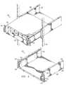
- FIG. 1depicts mounting a chassis in a front facing orientation consistent with the teachings of the invention.
- FIG. 2depicts an embodiment of the inventive arrangement of the slide brackets and mounting shelf.
- FIG. 3depicts a slide bracket of FIGS. 1 and 2.
- FIG. 4depicts an embodiment of the invention mounting a chassis in a rear-facing orientation.
- FIG. 5depicts an alternative embodiment of the slide bracket shown in FIG. 3 .
- FIG. 6depicts an alternative embodiment of the inventive arrangement using the slide bracket of FIG. 5 .
- the inventionpreferably comprises a folded sheet metal slide bracket assembly and a folded sheet metal mounting shelf.
- Two slide bracketsare preferably used with one slide bracket supporting the left side of the chassis and the other supporting the right side of the chassis.
- the rack mount shelfis preferably connected to the rack through the use of screws and mounting holes.
- the slide bracketis preferably attached to the chassis by screws through holes and provides alignment and final positioning of the chassis within the rack.
- the slide bracket of the inventioncan be mounted on either side of the chassis. This allows the chassis to be mounted with either the front or rear of the chassis facing out of the front of the rack. This flexibility is desirable as some users require access to the front of the chassis, for example, to load/unload storage media, while other users prefer access to the rear of the chassis, for example, to allow connection/disconnection of cables.
- each slide bracketpreferably includes a flange, which together are used to position the chassis on the mounting shelf.
- the mounting shelfpreferably comprises flanges such that when the chassis is properly located on the mounting shelf, the flanges of the slide brackets align with the flanges of the mounting shelf. Fasteners or other forms of connectors can then be used to attach the slide bracket to the mounting shelf.
- FIG. 1depicts an arrangement of the inventive rack mount 100 for mounting chassis 103 into rack 101 .
- the inventive mount 100includes mounting shelf 102 which supports chassis or device or equipment 103 .
- Preferably attached to chassis 103are two slide brackets 104 , with one bracket being mounted on one side, e.g., left, and the other bracket being mounted on the other side, e.g., right.
- the inventive rack mount 100preferably does not include rack 101 or chassis 103 .
- Each slide bracket 104preferably includes a flange 105 that is located on the front distal end of the slide bracket 104 .
- Flange 105is used to position the chassis within the rack. As shown in FIG. 1, chassis 103 is being installed into (or removed from) the rack 101 . Flange 105 will stop the insertion of the chassis 103 when flange 105 encounters either rack 101 or mounting shelf 102 . Slide bracket 104 may then be attached to either rack 101 or mounting shelf 102 via connectors such as fasteners, screws, nuts and bolts, pins, adhesives, welds, hooks and slots, keyholes and keyhole standoffs, or any combination thereof.
- Mounting shelf 102is preferably attached to rack 101 by one or more connectors 204 (FIG. 2) which could comprise one or more pins, screws, nuts and bolts, adhesives, welds, fasteners, hooks and slots, keyholes and keyhole standoffs, or any combination thereof.
- connectors 204could comprise one or more pins, screws, nuts and bolts, adhesives, welds, fasteners, hooks and slots, keyholes and keyhole standoffs, or any combination thereof.
- mounting shelf 102may be sized so as to receive chassis 103 and be able to be attached to rack 101 .
- Mounting shelf 102may include adjustable supports or brackets (not shown) so as to attach to rack 101 . This means that the rack 101 does not have to be sized to exactly fit chassis 103 . Thus, rack 101 may be significantly larger than chassis 103 . As shown in FIG. 1 , the chassis is mounted into rack 101 so that the front 106 of chassis 103 is accessible at front of rack 101 .
- FIG. 2depicts a view similar to that of FIG. 1 except that chassis 103 is not present for easier viewing of the components of the invention.
- the inventionalso preferably includes two handles 201 , one of which is mounted on each flange 105 . Handles 201 allow for chassis 103 to be more easily installed into and/or removed from the rack 101 .
- FIG. 2also depicts a preferred embodiment wherein shelf 102 includes two flanges 202 , each of which is located so as to contact a respective flange 105 of slide brackets 104 when the chassis 103 is properly located in rack 101 .
- Flange 105 and flange 202preferably have colocated holes 203 which enables a connector to securely connect the slide brackets 104 , and hence, chassis 103 , to mounting shelf 102 .
- FIG. 3depicts an elevational view of one of the flanges 104 .
- Each flange 104would preferably have a chassis mounting system that would allow the chassis 103 to be mounted in either a front orientation or a rear orientation.
- mounting system 300preferably comprises hole sets 301 and 302 .
- Each hole setis specifically configured and placed on flange 104 to enable flange 104 to be attached to a side of chassis 103 .
- hole set 301may enable the left side of the chassis to be attached to flange 104
- hole set 302enables the right side of chassis 103 to be attached to flange 104 .
- flange 104could be attached to either side of chassis 103 .
- the mounting system 300could comprise one or more pins, screws, nuts and bolts, adhesives, welds, fasteners, hooks and slots, keyholes and keyhole standoffs, or any combination thereof.
- the flange shown in FIG. 3is oriented to attach to the left slide of chassis 103 .
- the flangewould be inverted to be attached to the right side of chassis 103 .
- holes 203 and hole sets 301 , 302are shown by way of example only. There could be more holes, fewer holes, holes located in different positions, different-sized holes, or whatever is needed to accommodate attachment of the flange 104 to the mounting shelf 102 or attachment with chassis 103 , respectively.
- the connectors 204are shown by way of example only, as there could be more connectors, fewer connectors, connectors located in different positions, different-sized connectors, or whatever is needed to accommodate attachment of the shelf 102 to rack 101 .
- FIG. 4depicts an arrangement of the chassis 103 in the rack 101 such that the rear 401 of chassis 103 is located at the front of rack 101 .
- FIG. 5depicts an alternative embodiment 500 of the slide bracket that can be used in arrangements of FIGS. 1, 2 and 4 in place of the slide bracket 104 shown in FIG. 3 .
- Slide bracket 500includes at least one additional flange, e.g. 501 and/or 502 .
- the additional flange(s) 501 , 502increase(s) the strength of the slide bracket 500 .
- slide bracket 500may be of sufficient height so that flange 501 interfaces with flange 503 of mounting shelf 102 , and thereby provide easier mounting of the chassis into the rack.
- bracket 104may also be of sufficient height so that its upper portion also interfaces with flange 503 .
- FIG. 6depicts an alternative embodiment 600 using the slide bracket 500 of FIG. 5 .
- the slide bracket:doesnot contact the upper flange 503 of the mounting shelf 102
- the upper portion of chassis 103may contact the upper flange 503 .
- the height of the chassis 103is limited by the height of the mounting shelf 102 .
- the flange 601 of mounting shelf 102does not contact chassis 103 .
- the flange 601preferably contacts the upper flange 501 of each slide bracket 500 . This would prevent vertical movement of the chassis, but would allow the chassis to be of any height.
Landscapes
- Engineering & Computer Science (AREA)
- Computer Hardware Design (AREA)
- General Engineering & Computer Science (AREA)
- Microelectronics & Electronic Packaging (AREA)
- Casings For Electric Apparatus (AREA)
- Mounting Of Printed Circuit Boards And The Like (AREA)
Abstract
Description
Claims (37)
Priority Applications (3)
| Application Number | Priority Date | Filing Date | Title |
|---|---|---|---|
| US10/073,478US6644481B2 (en) | 2002-02-11 | 2002-02-11 | Apparatus and method for rackmounting a chassis |
| US10/464,994US6789685B2 (en) | 2002-02-11 | 2003-06-18 | Apparatus and method for rackmounting a chassis |
| US10/740,093US7055701B2 (en) | 2002-02-11 | 2003-12-18 | Apparatus and method for rackmounting a chassis |
Applications Claiming Priority (1)
| Application Number | Priority Date | Filing Date | Title |
|---|---|---|---|
| US10/073,478US6644481B2 (en) | 2002-02-11 | 2002-02-11 | Apparatus and method for rackmounting a chassis |
Related Child Applications (1)
| Application Number | Title | Priority Date | Filing Date |
|---|---|---|---|
| US10/464,994ContinuationUS6789685B2 (en) | 2002-02-11 | 2003-06-18 | Apparatus and method for rackmounting a chassis |
Publications (2)
| Publication Number | Publication Date |
|---|---|
| US20030150823A1 US20030150823A1 (en) | 2003-08-14 |
| US6644481B2true US6644481B2 (en) | 2003-11-11 |
Family
ID=27659677
Family Applications (3)
| Application Number | Title | Priority Date | Filing Date |
|---|---|---|---|
| US10/073,478Expired - LifetimeUS6644481B2 (en) | 2002-02-11 | 2002-02-11 | Apparatus and method for rackmounting a chassis |
| US10/464,994Expired - Fee RelatedUS6789685B2 (en) | 2002-02-11 | 2003-06-18 | Apparatus and method for rackmounting a chassis |
| US10/740,093Expired - Fee RelatedUS7055701B2 (en) | 2002-02-11 | 2003-12-18 | Apparatus and method for rackmounting a chassis |
Family Applications After (2)
| Application Number | Title | Priority Date | Filing Date |
|---|---|---|---|
| US10/464,994Expired - Fee RelatedUS6789685B2 (en) | 2002-02-11 | 2003-06-18 | Apparatus and method for rackmounting a chassis |
| US10/740,093Expired - Fee RelatedUS7055701B2 (en) | 2002-02-11 | 2003-12-18 | Apparatus and method for rackmounting a chassis |
Country Status (1)
| Country | Link |
|---|---|
| US (3) | US6644481B2 (en) |
Cited By (32)
| Publication number | Priority date | Publication date | Assignee | Title |
|---|---|---|---|---|
| US20020104942A1 (en)* | 2000-11-07 | 2002-08-08 | Mimlitch Robert H. | Apparatus and method for adapting two-post rack systems to support four-post rack mounted equipment |
| US20040129657A1 (en)* | 2002-02-11 | 2004-07-08 | Dean Ronald P. | Apparatus and method for rackmounting a chassis |
| US20040188362A1 (en)* | 2003-03-28 | 2004-09-30 | Alvin Liu | Retaining assembly for rack cabinet |
| US6888069B1 (en)* | 2004-05-26 | 2005-05-03 | Nortel Networks Limited | Equipment tray for simplified insertion and removal of rack-mounted equipment |
| US6972961B2 (en) | 2002-10-01 | 2005-12-06 | Power-One, Inc. | Systems and methods for a tongue and groove arrangement for an electronic module and equipment rack |
| US20060157436A1 (en)* | 2005-01-18 | 2006-07-20 | Nec Corporation | Rack system, adapter, rack frame, support rail, and method of making a rack system |
| US7134558B1 (en)* | 2002-03-14 | 2006-11-14 | Innovation First, Inc. | Universal rack mountable shelf |
| US7201279B1 (en)* | 2002-07-18 | 2007-04-10 | Innovation First, Inc. | Sliding rack-mountable shelf for rack-mountable components |
| US20070178369A1 (en)* | 2006-02-02 | 2007-08-02 | William Conrardy | Tiered battery cabinet |
| USD556204S1 (en)* | 2006-05-16 | 2007-11-27 | Sun Microsystems, Inc. | Filler panel with integrated dust cover |
| US20070278915A1 (en)* | 2006-05-05 | 2007-12-06 | C&C Power, Inc. | Equipment cabinet |
| US20110194910A1 (en)* | 2010-02-09 | 2011-08-11 | Hong Fu Jin Precision Industry (Shenzhen) Co., Ltd . | Assembly having screw and nut |
| US8270325B2 (en) | 2006-02-21 | 2012-09-18 | Pacific Star Communications, Inc. | Mobile broadband communications system, such as a deployable self-contained portable system |
| US9167896B1 (en)* | 2014-10-21 | 2015-10-27 | Shuter Enterprise Co., Ltd. | Supporting rack assembly |
| USD742887S1 (en)* | 2015-07-22 | 2015-11-10 | Symbolic Io Corporation | Tray |
| USD743404S1 (en)* | 2015-07-22 | 2015-11-17 | Symbolic Io Corporation | Media tray |
| US9386847B1 (en)* | 2014-07-17 | 2016-07-12 | Austin Hardware And Supply, Inc. | Mounting system |
| USD773468S1 (en)* | 2015-11-10 | 2016-12-06 | Sunland International, Llc | Optical and SSD drive faceplate |
| USD773469S1 (en)* | 2015-11-10 | 2016-12-06 | Sunland International, Llc | Optical drive with removable SSD |
| US9848703B2 (en) | 2015-03-12 | 2017-12-26 | King Slide Works Co., Ltd. | Slide rail assembly |
| US9977719B1 (en) | 2013-02-01 | 2018-05-22 | Symbolic Io Corporation | Fast system state cloning |
| US10061514B2 (en) | 2015-04-15 | 2018-08-28 | Formulus Black Corporation | Method and apparatus for dense hyper IO digital retention |
| US10104799B2 (en)* | 2016-02-16 | 2018-10-16 | Ciena Corporation | Network element chassis tool and method for single person installation |
| US10120607B2 (en) | 2015-04-15 | 2018-11-06 | Formulus Black Corporation | Method and apparatus for dense hyper IO digital retention |
| US10133636B2 (en) | 2013-03-12 | 2018-11-20 | Formulus Black Corporation | Data storage and retrieval mediation system and methods for using same |
| US10327351B2 (en)* | 2016-10-26 | 2019-06-18 | MacStadium, Inc. | Sled, tray, and shelf assembly for computer data center |
| US20190364686A1 (en)* | 2018-05-25 | 2019-11-28 | Cisco Technology, Inc. | Quick release for online insertion and removal of a module in a distributed network system |
| US10572186B2 (en) | 2017-12-18 | 2020-02-25 | Formulus Black Corporation | Random access memory (RAM)-based computer systems, devices, and methods |
| US10725853B2 (en) | 2019-01-02 | 2020-07-28 | Formulus Black Corporation | Systems and methods for memory failure prevention, management, and mitigation |
| EP3958658A1 (en) | 2020-08-20 | 2022-02-23 | King Slide Works Co., Ltd. | Slide rail assembly |
| US20230092329A1 (en)* | 2021-09-20 | 2023-03-23 | Dell Products L.P. | Top of Stack Safety Rail |
| US11690451B2 (en) | 2021-03-10 | 2023-07-04 | King Slide Works Co., Ltd. | Slide rail mechanism and slide rail kit thereof |
Families Citing this family (28)
| Publication number | Priority date | Publication date | Assignee | Title |
|---|---|---|---|---|
| US7573713B2 (en)* | 2005-09-13 | 2009-08-11 | Pacific Star Communications | High velocity air cooling for electronic equipment |
| US7535861B2 (en) | 2005-10-07 | 2009-05-19 | Pacific Star Communications Inc. | Self-contained portable broadband communication system |
| US7301756B2 (en)* | 2006-03-23 | 2007-11-27 | Adc Telecommunications, Inc. | System for mounting modules in a rack mounted chassis |
| US20070247044A1 (en)* | 2006-04-25 | 2007-10-25 | International Business Machines Corporation | Self-Locating Rear Mount System and Method for Rack Mountable Equipment |
| US20080035588A1 (en)* | 2006-08-09 | 2008-02-14 | Super Micro Computer, Inc. | Device for loading computer equipment |
| TW200847144A (en)* | 2007-05-31 | 2008-12-01 | Acard Technology Corp | Removable hard disk module |
| US20100200716A1 (en)* | 2009-02-09 | 2010-08-12 | International Business Machines Corporation | Modular rack for electronic systems |
| US8550260B1 (en)* | 2009-09-25 | 2013-10-08 | Rockwell Collins, Inc. | Aircraft control panel assembly |
| CN102054517A (en)* | 2009-10-30 | 2011-05-11 | 鸿富锦精密工业(深圳)有限公司 | Magnetic mount assembly |
| CN102245000A (en)* | 2010-05-11 | 2011-11-16 | 鸿富锦精密工业(深圳)有限公司 | Electronic device combination |
| CN102455751A (en)* | 2010-10-18 | 2012-05-16 | 鸿富锦精密工业(深圳)有限公司 | Server device |
| TW201220023A (en)* | 2010-11-05 | 2012-05-16 | Inventec Corp | Server rack structure |
| US8582299B1 (en) | 2010-12-23 | 2013-11-12 | Amazon Technologies, Inc. | System with movable computing devices |
| TWM428616U (en)* | 2011-12-27 | 2012-05-01 | Hon Hai Prec Ind Co Ltd | Fixing structure of electronic device |
| TWI478652B (en)* | 2012-07-04 | 2015-03-21 | Hon Hai Prec Ind Co Ltd | Cabinet |
| US8739982B2 (en)* | 2012-10-16 | 2014-06-03 | Theodore J. Werner | Shelf-mounted handgun rack |
| US20140263108A1 (en)* | 2013-03-14 | 2014-09-18 | Milestone Av Technologies Llc | Modular stackable equipment rack |
| US9161625B2 (en) | 2013-11-08 | 2015-10-20 | King Slide Works Co., Ltd. | Slide rail assembly |
| US9370120B2 (en) | 2014-01-17 | 2016-06-14 | King Slide Works Co., Ltd. | Slide assembly |
| US10172453B1 (en)* | 2014-02-28 | 2019-01-08 | VCE IP Holding Company LLC | System equipment carriers and related methods |
| TWI598026B (en)* | 2015-09-18 | 2017-09-01 | King Slide Works Co Ltd | Slide rail assembly with interlock device |
| US10765030B2 (en)* | 2015-10-30 | 2020-09-01 | Vapor IO Inc. | Adapters for rack-mounted computing equipment |
| US10034407B2 (en) | 2016-07-22 | 2018-07-24 | Intel Corporation | Storage sled for a data center |
| AT518661B1 (en) | 2016-08-23 | 2017-12-15 | Patchbox Gmbh | mounting aid |
| TWI632882B (en) | 2017-01-19 | 2018-08-21 | 川湖科技股份有限公司 | Slide rail assembly |
| US11419235B2 (en)* | 2017-11-07 | 2022-08-16 | International Business Machines Corporation | Vibration shock mitigation for components in a server rack |
| US10687438B2 (en)* | 2018-08-28 | 2020-06-16 | Quanta Computer Inc. | Rail assembly for storage rack |
| US20240237255A9 (en)* | 2022-10-20 | 2024-07-11 | Dell Products L.P. | Over-rack component track system for modular data centers |
Citations (13)
| Publication number | Priority date | Publication date | Assignee | Title |
|---|---|---|---|---|
| US3228532A (en)* | 1963-05-27 | 1966-01-11 | Manson Lab Inc | Electronic equipment mounting and housing arrangements |
| US5571256A (en)* | 1994-10-25 | 1996-11-05 | Compaq Computer Corporation | Server drawer slide mount apparatus for a rack-mounted computer system |
| US5726864A (en)* | 1995-08-24 | 1998-03-10 | Digital Equipment Corporation | Cage system |
| US5808867A (en)* | 1997-03-27 | 1998-09-15 | Wang; Joseph | Power supply assembly |
| US6185092B1 (en)* | 1999-09-03 | 2001-02-06 | Compaq Computer Corporation | Computer system with in-line switchbox mounting |
| US6201690B1 (en)* | 1998-09-01 | 2001-03-13 | Emc Corporation | Rack console assembly |
| US6227630B1 (en)* | 1998-04-08 | 2001-05-08 | International Business Machines Corporation | Accessory mounting for digital computer |
| US6256195B1 (en)* | 1999-04-06 | 2001-07-03 | Hon Hai Precision Ind. Co., Ltd. | Securing device of computer data storage |
| US6297962B1 (en)* | 2000-01-21 | 2001-10-02 | Dell Usa, L.P. | Apparatus for providing displacement to a slide mounted chassis in a rack |
| US6305556B1 (en)* | 2000-10-26 | 2001-10-23 | Hewlett-Packard Company | Cable management solution for rack-mounted computers |
| US6370022B1 (en)* | 1999-07-13 | 2002-04-09 | Gateway, Inc. | Screwless computer drive assembly |
| US6388873B1 (en)* | 1999-08-20 | 2002-05-14 | Western Digital Technologies, Inc. | Disk drive including resilient securing system providing relative movement between side rails and head disk assembly to accommodate side rails engaging guide channels in a chassis |
| US6481809B1 (en)* | 2000-09-13 | 2002-11-19 | Acorn Product Development, Inc. | Sliding module for computer components |
Family Cites Families (4)
| Publication number | Priority date | Publication date | Assignee | Title |
|---|---|---|---|---|
| US6015053A (en)* | 1997-09-19 | 2000-01-18 | Honeyware, Inc. | All-plastic shelf unit module having a sliding drawer |
| JP4358466B2 (en)* | 2001-09-04 | 2009-11-04 | アライドテレシスホールディングス株式会社 | Communication equipment storage device |
| US6644481B2 (en)* | 2002-02-11 | 2003-11-11 | Hewlett-Packard Development Company, L.P. | Apparatus and method for rackmounting a chassis |
| US7086539B2 (en)* | 2002-10-21 | 2006-08-08 | Adc Telecommunications, Inc. | High density panel with rotating tray |
- 2002
- 2002-02-11USUS10/073,478patent/US6644481B2/ennot_activeExpired - Lifetime
- 2003
- 2003-06-18USUS10/464,994patent/US6789685B2/ennot_activeExpired - Fee Related
- 2003-12-18USUS10/740,093patent/US7055701B2/ennot_activeExpired - Fee Related
Patent Citations (13)
| Publication number | Priority date | Publication date | Assignee | Title |
|---|---|---|---|---|
| US3228532A (en)* | 1963-05-27 | 1966-01-11 | Manson Lab Inc | Electronic equipment mounting and housing arrangements |
| US5571256A (en)* | 1994-10-25 | 1996-11-05 | Compaq Computer Corporation | Server drawer slide mount apparatus for a rack-mounted computer system |
| US5726864A (en)* | 1995-08-24 | 1998-03-10 | Digital Equipment Corporation | Cage system |
| US5808867A (en)* | 1997-03-27 | 1998-09-15 | Wang; Joseph | Power supply assembly |
| US6227630B1 (en)* | 1998-04-08 | 2001-05-08 | International Business Machines Corporation | Accessory mounting for digital computer |
| US6201690B1 (en)* | 1998-09-01 | 2001-03-13 | Emc Corporation | Rack console assembly |
| US6256195B1 (en)* | 1999-04-06 | 2001-07-03 | Hon Hai Precision Ind. Co., Ltd. | Securing device of computer data storage |
| US6370022B1 (en)* | 1999-07-13 | 2002-04-09 | Gateway, Inc. | Screwless computer drive assembly |
| US6388873B1 (en)* | 1999-08-20 | 2002-05-14 | Western Digital Technologies, Inc. | Disk drive including resilient securing system providing relative movement between side rails and head disk assembly to accommodate side rails engaging guide channels in a chassis |
| US6185092B1 (en)* | 1999-09-03 | 2001-02-06 | Compaq Computer Corporation | Computer system with in-line switchbox mounting |
| US6297962B1 (en)* | 2000-01-21 | 2001-10-02 | Dell Usa, L.P. | Apparatus for providing displacement to a slide mounted chassis in a rack |
| US6481809B1 (en)* | 2000-09-13 | 2002-11-19 | Acorn Product Development, Inc. | Sliding module for computer components |
| US6305556B1 (en)* | 2000-10-26 | 2001-10-23 | Hewlett-Packard Company | Cable management solution for rack-mounted computers |
Cited By (57)
| Publication number | Priority date | Publication date | Assignee | Title |
|---|---|---|---|---|
| US20020104942A1 (en)* | 2000-11-07 | 2002-08-08 | Mimlitch Robert H. | Apparatus and method for adapting two-post rack systems to support four-post rack mounted equipment |
| US7591056B2 (en) | 2000-11-07 | 2009-09-22 | Innovation First, Inc. | Method for adapting two-post rack systems to support four-post rack mounted equipment |
| US20080175659A1 (en)* | 2000-11-07 | 2008-07-24 | Innovation First, Inc. | Apparatus and method for adapting two-post rack systems to support four-post rack mounted equipment |
| US7275646B2 (en) | 2000-11-07 | 2007-10-02 | Innovation First, Inc. | Apparatus and method for adapting two-post rack systems to support four-post rack mounted equipment |
| US20040129657A1 (en)* | 2002-02-11 | 2004-07-08 | Dean Ronald P. | Apparatus and method for rackmounting a chassis |
| US7055701B2 (en)* | 2002-02-11 | 2006-06-06 | Hewlett-Packard Development Company, L.P. | Apparatus and method for rackmounting a chassis |
| US7866488B2 (en) | 2002-03-14 | 2011-01-11 | Innovation First, Inc. | Universal rack mountable shelf |
| US20090218301A1 (en)* | 2002-03-14 | 2009-09-03 | Innovation First, Inc., A Texas Corporation | Universal rack mountable shelf |
| US7134558B1 (en)* | 2002-03-14 | 2006-11-14 | Innovation First, Inc. | Universal rack mountable shelf |
| US20070227992A1 (en)* | 2002-07-18 | 2007-10-04 | Innovation First, Inc., A Texas Corporation | Sliding Rack-Mountable Shelf for Rack-Mountable Components |
| US7806277B2 (en) | 2002-07-18 | 2010-10-05 | Innovation First, Inc. | Sliding rack-mountable shelf for rack-mountable components |
| US7201279B1 (en)* | 2002-07-18 | 2007-04-10 | Innovation First, Inc. | Sliding rack-mountable shelf for rack-mountable components |
| US6972961B2 (en) | 2002-10-01 | 2005-12-06 | Power-One, Inc. | Systems and methods for a tongue and groove arrangement for an electronic module and equipment rack |
| US6929336B2 (en)* | 2003-03-28 | 2005-08-16 | Hon Hai Precision Ind. Co., Ltd. | Retaining assembly for rack cabinet |
| US20040188362A1 (en)* | 2003-03-28 | 2004-09-30 | Alvin Liu | Retaining assembly for rack cabinet |
| US6888069B1 (en)* | 2004-05-26 | 2005-05-03 | Nortel Networks Limited | Equipment tray for simplified insertion and removal of rack-mounted equipment |
| US20060157436A1 (en)* | 2005-01-18 | 2006-07-20 | Nec Corporation | Rack system, adapter, rack frame, support rail, and method of making a rack system |
| US10312484B2 (en) | 2006-02-02 | 2019-06-04 | C & C Power, Inc. | Tiered battery cabinet |
| US9312525B2 (en) | 2006-02-02 | 2016-04-12 | C & C Power Inc | Tiered battery cabinet |
| US20070178369A1 (en)* | 2006-02-02 | 2007-08-02 | William Conrardy | Tiered battery cabinet |
| US9112205B2 (en) | 2006-02-02 | 2015-08-18 | C & C Power | Tiered battery cabinet |
| US8100271B2 (en) | 2006-02-02 | 2012-01-24 | C & C Power | Tiered battery cabinet |
| US8270325B2 (en) | 2006-02-21 | 2012-09-18 | Pacific Star Communications, Inc. | Mobile broadband communications system, such as a deployable self-contained portable system |
| US9301408B2 (en) | 2006-05-05 | 2016-03-29 | C & C Power, Inc. | Equipment cabinet |
| US20070278915A1 (en)* | 2006-05-05 | 2007-12-06 | C&C Power, Inc. | Equipment cabinet |
| US9755200B2 (en) | 2006-05-05 | 2017-09-05 | C & C Pwere, Inc. | Equipment cabinet |
| US8721010B2 (en)* | 2006-05-05 | 2014-05-13 | C&C Power, Inc | Equipment cabinet |
| USD556204S1 (en)* | 2006-05-16 | 2007-11-27 | Sun Microsystems, Inc. | Filler panel with integrated dust cover |
| US20110194910A1 (en)* | 2010-02-09 | 2011-08-11 | Hong Fu Jin Precision Industry (Shenzhen) Co., Ltd . | Assembly having screw and nut |
| US10789137B2 (en) | 2013-02-01 | 2020-09-29 | Formulus Black Corporation | Fast system state cloning |
| US9977719B1 (en) | 2013-02-01 | 2018-05-22 | Symbolic Io Corporation | Fast system state cloning |
| US10133636B2 (en) | 2013-03-12 | 2018-11-20 | Formulus Black Corporation | Data storage and retrieval mediation system and methods for using same |
| US9386847B1 (en)* | 2014-07-17 | 2016-07-12 | Austin Hardware And Supply, Inc. | Mounting system |
| US9167896B1 (en)* | 2014-10-21 | 2015-10-27 | Shuter Enterprise Co., Ltd. | Supporting rack assembly |
| US9848703B2 (en) | 2015-03-12 | 2017-12-26 | King Slide Works Co., Ltd. | Slide rail assembly |
| US10346047B2 (en) | 2015-04-15 | 2019-07-09 | Formulus Black Corporation | Method and apparatus for dense hyper IO digital retention |
| US10061514B2 (en) | 2015-04-15 | 2018-08-28 | Formulus Black Corporation | Method and apparatus for dense hyper IO digital retention |
| US10606482B2 (en) | 2015-04-15 | 2020-03-31 | Formulus Black Corporation | Method and apparatus for dense hyper IO digital retention |
| US10120607B2 (en) | 2015-04-15 | 2018-11-06 | Formulus Black Corporation | Method and apparatus for dense hyper IO digital retention |
| USD743404S1 (en)* | 2015-07-22 | 2015-11-17 | Symbolic Io Corporation | Media tray |
| USD742887S1 (en)* | 2015-07-22 | 2015-11-10 | Symbolic Io Corporation | Tray |
| USD773469S1 (en)* | 2015-11-10 | 2016-12-06 | Sunland International, Llc | Optical drive with removable SSD |
| USD773468S1 (en)* | 2015-11-10 | 2016-12-06 | Sunland International, Llc | Optical and SSD drive faceplate |
| US10104799B2 (en)* | 2016-02-16 | 2018-10-16 | Ciena Corporation | Network element chassis tool and method for single person installation |
| US20190297743A1 (en)* | 2016-10-26 | 2019-09-26 | MacStadium, Inc. | Sled, tray, and shelf assembly for computer data center |
| US10602636B2 (en)* | 2016-10-26 | 2020-03-24 | MacStadium, Inc. | Sled, tray, and shelf assembly for computer data center |
| US10327351B2 (en)* | 2016-10-26 | 2019-06-18 | MacStadium, Inc. | Sled, tray, and shelf assembly for computer data center |
| US10572186B2 (en) | 2017-12-18 | 2020-02-25 | Formulus Black Corporation | Random access memory (RAM)-based computer systems, devices, and methods |
| US10932387B2 (en)* | 2018-05-25 | 2021-02-23 | Cisco Technology, Inc. | Quick release for online insertion and removal of a module in a distributed network system |
| US20190364686A1 (en)* | 2018-05-25 | 2019-11-28 | Cisco Technology, Inc. | Quick release for online insertion and removal of a module in a distributed network system |
| US10725853B2 (en) | 2019-01-02 | 2020-07-28 | Formulus Black Corporation | Systems and methods for memory failure prevention, management, and mitigation |
| EP3958658A1 (en) | 2020-08-20 | 2022-02-23 | King Slide Works Co., Ltd. | Slide rail assembly |
| US11395435B2 (en) | 2020-08-20 | 2022-07-19 | King Slide Works Co., Ltd. | Slide rail assembly |
| US11690451B2 (en) | 2021-03-10 | 2023-07-04 | King Slide Works Co., Ltd. | Slide rail mechanism and slide rail kit thereof |
| US11950695B2 (en) | 2021-03-10 | 2024-04-09 | King Slide Works Co., Ltd. | Slide rail mechanism and slide rail kit thereof |
| US20230092329A1 (en)* | 2021-09-20 | 2023-03-23 | Dell Products L.P. | Top of Stack Safety Rail |
| US11844190B2 (en)* | 2021-09-20 | 2023-12-12 | Dell Products L.P. | Top of stack safety rail |
Also Published As
| Publication number | Publication date |
|---|---|
| US20030150823A1 (en) | 2003-08-14 |
| US7055701B2 (en) | 2006-06-06 |
| US20040129657A1 (en) | 2004-07-08 |
| US6789685B2 (en) | 2004-09-14 |
| US20030205540A1 (en) | 2003-11-06 |
Similar Documents
| Publication | Publication Date | Title |
|---|---|---|
| US6644481B2 (en) | Apparatus and method for rackmounting a chassis | |
| US9699932B2 (en) | Method and apparatus for mounting rack components on racks | |
| US6422399B1 (en) | Rack system and method having tool-less releasable arm assembly | |
| US7012808B2 (en) | Multi-configurable telecommunications rack mounting system and method incorporating same | |
| US8358502B2 (en) | Rack kit | |
| US8371666B2 (en) | Container data center | |
| US9433114B2 (en) | Service shelf for electronic cabinet | |
| CA2641277A1 (en) | Tiered battery cabinet | |
| US20060134953A1 (en) | Electronic module latching mechanism | |
| EP2274963A1 (en) | Power supply assembly for server rack and method for mounting power supply for server rack | |
| US9955607B1 (en) | Electronic equipment vertical mount and stack rack | |
| EP4009754A1 (en) | Interoperable server power board support structure | |
| CN212136977U (en) | Simple to operate's assembled high-voltage board | |
| US20080290051A1 (en) | Standalone open frame | |
| US20050162837A1 (en) | Apparatus for attaching and detaching circuit boards | |
| US20040189162A1 (en) | Tool-less attachment and removal of components in a computer enclosure | |
| Cisco | Upgrading Rackmounted Nodes | |
| Cisco | Upgrading Rack-Mounted Nodes | |
| Cisco | Installation, with Customer Cabinet | |
| Cisco | Upgrading Rack-Mounted Nodes | |
| Cisco | Upgrading Rackmounted Nodes | |
| Cisco | Upgrading Rack-Mounted Nodes | |
| Cisco | Upgrading Rack-Mounted Nodes | |
| Cisco | Upgrading Rack-Mounted Nodes | |
| Cisco | Upgrading Rack-Mounted Nodes |
Legal Events
| Date | Code | Title | Description |
|---|---|---|---|
| AS | Assignment | Owner name:HEWLETT-PACKARD COMPANY, COLORADO Free format text:ASSIGNMENT OF ASSIGNORS INTEREST;ASSIGNORS:DEAN, RONALD P.;TUCKER, SEAN W.;REEL/FRAME:012971/0096 Effective date:20020129 | |
| AS | Assignment | Owner name:HEWLETT-PACKARD DEVELOPMENT COMPANY, L.P., COLORADO Free format text:ASSIGNMENT OF ASSIGNORS INTEREST;ASSIGNOR:HEWLETT-PACKARD COMPANY;REEL/FRAME:013776/0928 Effective date:20030131 Owner name:HEWLETT-PACKARD DEVELOPMENT COMPANY, L.P., COLORAD Free format text:ASSIGNMENT OF ASSIGNORS INTEREST;ASSIGNOR:HEWLETT-PACKARD COMPANY;REEL/FRAME:013776/0928 Effective date:20030131 Owner name:HEWLETT-PACKARD DEVELOPMENT COMPANY, L.P.,COLORADO Free format text:ASSIGNMENT OF ASSIGNORS INTEREST;ASSIGNOR:HEWLETT-PACKARD COMPANY;REEL/FRAME:013776/0928 Effective date:20030131 | |
| STCF | Information on status: patent grant | Free format text:PATENTED CASE | |
| FPAY | Fee payment | Year of fee payment:4 | |
| FPAY | Fee payment | Year of fee payment:8 | |
| REMI | Maintenance fee reminder mailed | ||
| AS | Assignment | Owner name:HEWLETT PACKARD ENTERPRISE DEVELOPMENT LP, TEXAS Free format text:ASSIGNMENT OF ASSIGNORS INTEREST;ASSIGNOR:HEWLETT-PACKARD DEVELOPMENT COMPANY, L.P.;REEL/FRAME:037079/0001 Effective date:20151027 | |
| FPAY | Fee payment | Year of fee payment:12 | |
| SULP | Surcharge for late payment | Year of fee payment:11 | |
| AS | Assignment | Owner name:OT PATENT ESCROW, LLC, ILLINOIS Free format text:PATENT ASSIGNMENT, SECURITY INTEREST, AND LIEN AGREEMENT;ASSIGNORS:HEWLETT PACKARD ENTERPRISE DEVELOPMENT LP;HEWLETT PACKARD ENTERPRISE COMPANY;REEL/FRAME:055269/0001 Effective date:20210115 | |
| AS | Assignment | Owner name:VALTRUS INNOVATIONS LIMITED, IRELAND Free format text:ASSIGNMENT OF ASSIGNORS INTEREST;ASSIGNOR:OT PATENT ESCROW, LLC;REEL/FRAME:056157/0492 Effective date:20210503 |