US6644428B2 - Automatic axle traction control - Google Patents
Automatic axle traction controlDownload PDFInfo
- Publication number
- US6644428B2 US6644428B2US09/873,440US87344001AUS6644428B2US 6644428 B2US6644428 B2US 6644428B2US 87344001 AUS87344001 AUS 87344001AUS 6644428 B2US6644428 B2US 6644428B2
- Authority
- US
- United States
- Prior art keywords
- axle
- axle output
- output shaft
- wheel
- speed range
- Prior art date
- Legal status (The legal status is an assumption and is not a legal conclusion. Google has not performed a legal analysis and makes no representation as to the accuracy of the status listed.)
- Expired - Lifetime, expires
Links
- 230000007246mechanismEffects0.000claimsdescription15
- 230000008878couplingEffects0.000claimsdescription5
- 238000010168coupling processMethods0.000claimsdescription5
- 238000005859coupling reactionMethods0.000claimsdescription5
- 230000003213activating effectEffects0.000claims5
- 230000005540biological transmissionEffects0.000description3
- 238000005516engineering processMethods0.000description3
- 238000000034methodMethods0.000description3
- 238000002485combustion reactionMethods0.000description2
- 238000012544monitoring processMethods0.000description2
- 230000002411adverseEffects0.000description1
- 239000000446fuelSubstances0.000description1
- 239000011159matrix materialSubstances0.000description1
- 238000012986modificationMethods0.000description1
- 230000004048modificationEffects0.000description1
- 230000009467reductionEffects0.000description1
- 238000012163sequencing techniqueMethods0.000description1
Images


Classifications
- B—PERFORMING OPERATIONS; TRANSPORTING
- B60—VEHICLES IN GENERAL
- B60T—VEHICLE BRAKE CONTROL SYSTEMS OR PARTS THEREOF; BRAKE CONTROL SYSTEMS OR PARTS THEREOF, IN GENERAL; ARRANGEMENT OF BRAKING ELEMENTS ON VEHICLES IN GENERAL; PORTABLE DEVICES FOR PREVENTING UNWANTED MOVEMENT OF VEHICLES; VEHICLE MODIFICATIONS TO FACILITATE COOLING OF BRAKES
- B60T8/00—Arrangements for adjusting wheel-braking force to meet varying vehicular or ground-surface conditions, e.g. limiting or varying distribution of braking force
- B60T8/17—Using electrical or electronic regulation means to control braking
- B60T8/175—Brake regulation specially adapted to prevent excessive wheel spin during vehicle acceleration, e.g. for traction control
- B—PERFORMING OPERATIONS; TRANSPORTING
- B60—VEHICLES IN GENERAL
- B60K—ARRANGEMENT OR MOUNTING OF PROPULSION UNITS OR OF TRANSMISSIONS IN VEHICLES; ARRANGEMENT OR MOUNTING OF PLURAL DIVERSE PRIME-MOVERS IN VEHICLES; AUXILIARY DRIVES FOR VEHICLES; INSTRUMENTATION OR DASHBOARDS FOR VEHICLES; ARRANGEMENTS IN CONNECTION WITH COOLING, AIR INTAKE, GAS EXHAUST OR FUEL SUPPLY OF PROPULSION UNITS IN VEHICLES
- B60K17/00—Arrangement or mounting of transmissions in vehicles
- B60K17/34—Arrangement or mounting of transmissions in vehicles for driving both front and rear wheels, e.g. four wheel drive vehicles
- B60K17/344—Arrangement or mounting of transmissions in vehicles for driving both front and rear wheels, e.g. four wheel drive vehicles having a transfer gear
- B—PERFORMING OPERATIONS; TRANSPORTING
- B60—VEHICLES IN GENERAL
- B60K—ARRANGEMENT OR MOUNTING OF PROPULSION UNITS OR OF TRANSMISSIONS IN VEHICLES; ARRANGEMENT OR MOUNTING OF PLURAL DIVERSE PRIME-MOVERS IN VEHICLES; AUXILIARY DRIVES FOR VEHICLES; INSTRUMENTATION OR DASHBOARDS FOR VEHICLES; ARRANGEMENTS IN CONNECTION WITH COOLING, AIR INTAKE, GAS EXHAUST OR FUEL SUPPLY OF PROPULSION UNITS IN VEHICLES
- B60K23/00—Arrangement or mounting of control devices for vehicle transmissions, or parts thereof, not otherwise provided for
- B60K23/08—Arrangement or mounting of control devices for vehicle transmissions, or parts thereof, not otherwise provided for for changing number of driven wheels, for switching from driving one axle to driving two or more axles
- B60K23/0808—Arrangement or mounting of control devices for vehicle transmissions, or parts thereof, not otherwise provided for for changing number of driven wheels, for switching from driving one axle to driving two or more axles for varying torque distribution between driven axles, e.g. by transfer clutch
- B—PERFORMING OPERATIONS; TRANSPORTING
- B60—VEHICLES IN GENERAL
- B60K—ARRANGEMENT OR MOUNTING OF PROPULSION UNITS OR OF TRANSMISSIONS IN VEHICLES; ARRANGEMENT OR MOUNTING OF PLURAL DIVERSE PRIME-MOVERS IN VEHICLES; AUXILIARY DRIVES FOR VEHICLES; INSTRUMENTATION OR DASHBOARDS FOR VEHICLES; ARRANGEMENTS IN CONNECTION WITH COOLING, AIR INTAKE, GAS EXHAUST OR FUEL SUPPLY OF PROPULSION UNITS IN VEHICLES
- B60K28/00—Safety devices for propulsion-unit control, specially adapted for, or arranged in, vehicles, e.g. preventing fuel supply or ignition in the event of potentially dangerous conditions
- B60K28/10—Safety devices for propulsion-unit control, specially adapted for, or arranged in, vehicles, e.g. preventing fuel supply or ignition in the event of potentially dangerous conditions responsive to conditions relating to the vehicle
- B60K28/16—Safety devices for propulsion-unit control, specially adapted for, or arranged in, vehicles, e.g. preventing fuel supply or ignition in the event of potentially dangerous conditions responsive to conditions relating to the vehicle responsive to, or preventing, spinning or skidding of wheels
- B60K28/165—Safety devices for propulsion-unit control, specially adapted for, or arranged in, vehicles, e.g. preventing fuel supply or ignition in the event of potentially dangerous conditions responsive to conditions relating to the vehicle responsive to, or preventing, spinning or skidding of wheels acting on elements of the vehicle drive train other than the propulsion unit and brakes, e.g. transmission, clutch, differential
- B—PERFORMING OPERATIONS; TRANSPORTING
- B60—VEHICLES IN GENERAL
- B60W—CONJOINT CONTROL OF VEHICLE SUB-UNITS OF DIFFERENT TYPE OR DIFFERENT FUNCTION; CONTROL SYSTEMS SPECIALLY ADAPTED FOR HYBRID VEHICLES; ROAD VEHICLE DRIVE CONTROL SYSTEMS FOR PURPOSES NOT RELATED TO THE CONTROL OF A PARTICULAR SUB-UNIT
- B60W10/00—Conjoint control of vehicle sub-units of different type or different function
- B60W10/04—Conjoint control of vehicle sub-units of different type or different function including control of propulsion units
- B60W10/06—Conjoint control of vehicle sub-units of different type or different function including control of propulsion units including control of combustion engines
- B—PERFORMING OPERATIONS; TRANSPORTING
- B60—VEHICLES IN GENERAL
- B60W—CONJOINT CONTROL OF VEHICLE SUB-UNITS OF DIFFERENT TYPE OR DIFFERENT FUNCTION; CONTROL SYSTEMS SPECIALLY ADAPTED FOR HYBRID VEHICLES; ROAD VEHICLE DRIVE CONTROL SYSTEMS FOR PURPOSES NOT RELATED TO THE CONTROL OF A PARTICULAR SUB-UNIT
- B60W10/00—Conjoint control of vehicle sub-units of different type or different function
- B60W10/12—Conjoint control of vehicle sub-units of different type or different function including control of differentials
- B60W10/14—Central differentials for dividing torque between front and rear axles
- B—PERFORMING OPERATIONS; TRANSPORTING
- B60—VEHICLES IN GENERAL
- B60W—CONJOINT CONTROL OF VEHICLE SUB-UNITS OF DIFFERENT TYPE OR DIFFERENT FUNCTION; CONTROL SYSTEMS SPECIALLY ADAPTED FOR HYBRID VEHICLES; ROAD VEHICLE DRIVE CONTROL SYSTEMS FOR PURPOSES NOT RELATED TO THE CONTROL OF A PARTICULAR SUB-UNIT
- B60W30/00—Purposes of road vehicle drive control systems not related to the control of a particular sub-unit, e.g. of systems using conjoint control of vehicle sub-units
- B60W30/18—Propelling the vehicle
- B60W30/18172—Preventing, or responsive to skidding of wheels
- B—PERFORMING OPERATIONS; TRANSPORTING
- B60—VEHICLES IN GENERAL
- B60T—VEHICLE BRAKE CONTROL SYSTEMS OR PARTS THEREOF; BRAKE CONTROL SYSTEMS OR PARTS THEREOF, IN GENERAL; ARRANGEMENT OF BRAKING ELEMENTS ON VEHICLES IN GENERAL; PORTABLE DEVICES FOR PREVENTING UNWANTED MOVEMENT OF VEHICLES; VEHICLE MODIFICATIONS TO FACILITATE COOLING OF BRAKES
- B60T2270/00—Further aspects of brake control systems not otherwise provided for
- B60T2270/20—ASR control systems
- B60T2270/202—ASR control systems for all-wheel drive vehicles
- B—PERFORMING OPERATIONS; TRANSPORTING
- B60—VEHICLES IN GENERAL
- B60W—CONJOINT CONTROL OF VEHICLE SUB-UNITS OF DIFFERENT TYPE OR DIFFERENT FUNCTION; CONTROL SYSTEMS SPECIALLY ADAPTED FOR HYBRID VEHICLES; ROAD VEHICLE DRIVE CONTROL SYSTEMS FOR PURPOSES NOT RELATED TO THE CONTROL OF A PARTICULAR SUB-UNIT
- B60W2520/00—Input parameters relating to overall vehicle dynamics
- B60W2520/28—Wheel speed
Definitions
- This inventionrelates to a method and apparatus for controlling engine and brake torque to selectively engage a front drive axle to provide all wheel drive under optimal conditions.
- Vehiclesutilize all wheel drive systems to achieve improved vehicle control under poor road conditions. All wheel drives for trucks equipped with geared front axle clutched transfer cases are normally engaged and disengaged by a vehicle operator or are engaged full time. Engagement systems can be manually controlled by the operator or can be automatically controlled to engage and disengage the front drive axle. Typically automatic control systems utilize electronic controllers that monitor front and rear axle speeds. When the rotational speed of both the front and rear axles are within a certain range, the controller automatically initiates a shift to engage the front axle.
- This automatic controlled engagement and disengagement of the front axleis typically initiated independently from the ground conditions.
- engagement of the front axlemay not be required or may be poorly timed to maintain vehicle tractive effort.
- Unnecessary engagement of the front axleresults in additional wear of the components, which is undesirable.
- poorly time shiftscan damage transfer case and axle components resulting in vehicle downtime and increased costs for replacement components.
- An all wheel drive systemincludes a transfer case assembly that is transfers driving torque from a vehicle engine to vehicle drive axles.
- the transfer caseincludes an input shaft that receives power source output torque, a rear axle output shaft for transferring driving torque from the transfer case to the rear drive axle, and a front axle output shaft that is selectively engaged to the front drive axle under predetermined conditions to achieve all wheel drive.
- a controllerdetermines the optimal conditions for the engagement and disengagement of the front axle.
- the controllerdetermines if there is wheel slippage by monitoring the various wheel speeds of the axles. If there is wheel slippage, the controller determines whether or not the input shaft and the rear axle output shaft are both within a predetermined speed range. If the input shaft and the rear axle output shaft are within the predetermined speed range and there is wheel slip, the controller initiates engagement of the front drive axle. If the input shaft and the rear axle output shaft are not within the predetermined speed range, the controller controls the engine output torque and/or wheel brake torque to bring the input shaft and the rear axle output shaft both within the predetermined rotational speed range.
- a typical vehicle drive trainincludes an internal combustion engine or other power source, transmission, transfer case, front drive axle with wheel brakes, and rear drive axle with wheel brakes.
- the preferred inventive method for coupling the transfer case to the front drive axle during wheel slip to achieve all wheel driveincludes the following steps.
- the input shaft of the transfer caseis coupled to the power source that produces an output torque.
- the rear drive axleis coupled to a rear output shaft of the transfer case.
- a sensor systemmeasures wheel speed and the controller determines whether or not there is wheel slip. At least one of the output torque or braking torque is controlled to bring the input shaft and the rear output shaft within the predetermined speed range.
- the front output shaft of the transfer caseis coupled to the front drive axle to achieve all wheel drive when the input shaft and the rear output shaft are within the predetermined speed range.
- the subject inventionprovides an improved control system for axle engagement and disengagement that takes into account input and output shaft speeds of the transfer case as well as ground conditions to provide optimal axle engagement shifts.
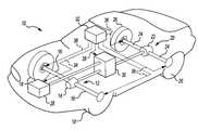
- FIG. 1is a schematic view of a powertrain system incorporating the subject invention.
- FIG. 2is a schematic view of a control system for the subject invention.
- FIG. 3is a cross-sectional view of a typical transfer case as used with the subject invention.
- FIG. 1A typical vehicle powertrain 10 is shown in FIG. 1 .
- the powertrain 10includes a front drive axle 12 having a center differential 14 for driving a first pair of axle shafts 16 , which in turn drive front wheels 18 mounted at opposite ends of the front drive axle 12 .
- the powertrain 10also includes a rear drive axle 20 with a center differential 22 for driving a second pair of axle shafts 24 , which in turn drive rear wheels 26 mounted at opposite ends of the rear drive axle 20 .
- a power source 28provides the driving torque to drive the axles 12 , 20 .
- a transfer case 30is used to transfer the driving torque from the power source 28 to the front 12 and rear 20 drive axles.
- the rear drive axle 20is always engaged with the transfer case 30 to provide the vehicle with rear wheel drive.
- the front drive axle 12is selectively engagable with the transfer case 30 to provide all wheel drive under predetermined conditions.
- ground conditionsare poor, such as when there is ice or mud
- vehicle controli.e., tractive effort
- the power source 28can be any known power source in the art such as an internal combustion engine or electric motor.
- the power source 28can also incorporate additional components such as transmissions, power-take-offs, etc.
- the subject inventionrelates to a control system that determines when conditions are optimal to engage and disengage the front drive axle 12 .
- the control systemmonitors ground conditions and includes a central processor or electronic control unit (ECU) 32 that generates a power source control signal 34 and/or a wheel control signal 36 to provide optimal conditions for axle engagement.
- the ECU 32sends a transfer case control signal 38 to initiate shift engagement once the ECU 32 determines that conditions are optimal.
- each of the wheels 18 , 26includes a braking mechanism 40 for a brake-by-wire system.
- Any type of braking mechanism 40 known in the artcan be used including dry disc, drum, or wet disc and can be actuated by any known actuation method including hydraulic or pneumatic actuators.
- Wheel sensors 42are used to determine wheel speed for each of the wheels 18 , 26 and generate wheel speed signals 44 that are transmitted to the ECU 32 .
- the ECU 32can determine whether or not there is wheel slippage, i.e., poor ground conditions. Once the ECU 32 determines whether or not there is wheel slip the ECU determines whether speed conditions for the transfer case 30 and axles 12 , 20 are optimal to initiate a shift. This will be discussed in greater detail below.
- the transfer case 30is shown in greater detail in FIG. 3 .
- the transfer case 30includes an input shaft 50 that couples to the output of the power source 28 .
- the transfer case 30also includes a rear axle output shaft 52 that is coupled to the rear drive axle 20 and a front axle output shaft 54 that is selectively engaged with the front drive axle 12 .
- the shafts 50 , 52 , 54are supported on bearings 56 installed within a housing 58 .
- a gear assembly 60drivingly connects the input shaft 50 to the rear axle output shaft 52 .
- a first gear 60 ais mounted for rotation with the input shaft 50 .
- This first gearmeshes with a second gear 60 b , which meshes with a third gear 60 c mounted for rotation with the rear axle output shaft 52 .
- the gear assembly 60can provide a 1:1 ratio or can be configured to provide gear reduction if desired.
- a declutch mechanism 62is used to driving engage the front axle output shaft 54 to the rear axle output shaft 52 to engage the front drive axle 12 . Any known declutch mechanism can be used.
- the declutch 62includes an electrical connector 64 to connect the declutch 62 to the ECU 32 .
- the input shaft 50 and rear axle output shaft 52must both be within a predetermined speed range. If both shafts 50 , 52 are within the predetermined speed range the ECU 32 signals the declutch 62 to couple the front axle output shaft 54 to the rear axle output shaft 52 such that the shafts 52 , 54 rotate together. Thus, when engaged, the front 54 and rear 52 shafts rotate at the same speed. If the shafts 50 , 52 are not within the predetermined range, the ECU 32 initiates various control signals to bring the shafts 50 , 52 within the predetermined range.
- the control systemoperates in the following manner. First, the ECU 32 determines if there is wheel slippage by monitoring the various wheel speeds of the axles 12 , 20 . If there is wheel slippage, the ECU 32 determines whether or not the input shaft 50 and the rear axle output shaft 52 are both within the predetermined speed range. If the input shaft 50 and the rear axle output shaft 52 are within the predetermined speed range and there is wheel slip, the ECU 32 initiates engagement of the front drive axle 12 .
- the ECU 32prevents axle engagement until the shafts 50 , 52 are within the predetermined range.
- the ECU 32controls the shaft speeds by generating a power source control signal 34 to control the output torque and/or generating a braking control signal 36 to control wheel brake torque to bring the input shaft 50 and the rear axle output shaft 52 both within the predetermined rotational speed range.
- the braking torque and power source output torquecan be separately controlled or simultaneously controlled depending upon the ground conditions and wheel speeds. For vehicles that do not have brake-by-wire systems, only output torque is controlled. Alternatively, braking torque control can be solely utilized to bring the shafts 50 , 52 within the speed range.
- the ECU 32signals 38 the transfer case declutch mechanism 62 to disengage from the front drive axle 12 .
- the transfer casecould include a spring disengagement mechanism (not shown) or could operate under a time delay to ensure that disengagement does not occur before the desired traction is achieved.
- the subject control system for axle engagement and disengagementthat takes into account input and output shaft speeds of the transfer case as well as ground conditions to provide optimal axle engagement shifts.
- the automated control systemdetermines if there is slippage by sensing wheel speeds. If wheel slip is detected, the ECU 32 uses a defined logic matrix to initiate a controlled shift for front axle engagement. This controlled shift forces the front output shaft 54 and the rear output shaft 52 to be within the predetermined range by interrupting power source output torque along with sequencing a controlled wheel brake signal 36 . When the speed range requirement is satisfied, the shift is initiated to engage the front axle. Once the axle is engaged, the power source output torque resumes and the brakes 40 are released.
- Engine control technologyis currently used to provide optimal transmission shifts.
- Brake control technologyis currently used to provide anti-lock braking systems.
- the subject inventionutilizes benefits from both of these technologies to activate axle engagement drives to provide all wheel drive with shift-on-the fly.
Landscapes
- Engineering & Computer Science (AREA)
- Chemical & Material Sciences (AREA)
- Combustion & Propulsion (AREA)
- Transportation (AREA)
- Mechanical Engineering (AREA)
- Automation & Control Theory (AREA)
- Arrangement And Driving Of Transmission Devices (AREA)
Abstract
Description
Claims (15)
Priority Applications (2)
| Application Number | Priority Date | Filing Date | Title |
|---|---|---|---|
| US09/873,440US6644428B2 (en) | 2001-06-04 | 2001-06-04 | Automatic axle traction control |
| US10/666,712US7322436B2 (en) | 2001-06-04 | 2003-09-18 | Automatic axle traction control |
Applications Claiming Priority (1)
| Application Number | Priority Date | Filing Date | Title |
|---|---|---|---|
| US09/873,440US6644428B2 (en) | 2001-06-04 | 2001-06-04 | Automatic axle traction control |
Related Child Applications (1)
| Application Number | Title | Priority Date | Filing Date |
|---|---|---|---|
| US10/666,712DivisionUS7322436B2 (en) | 2001-06-04 | 2003-09-18 | Automatic axle traction control |
Publications (2)
| Publication Number | Publication Date |
|---|---|
| US20020179357A1 US20020179357A1 (en) | 2002-12-05 |
| US6644428B2true US6644428B2 (en) | 2003-11-11 |
Family
ID=25361636
Family Applications (2)
| Application Number | Title | Priority Date | Filing Date |
|---|---|---|---|
| US09/873,440Expired - LifetimeUS6644428B2 (en) | 2001-06-04 | 2001-06-04 | Automatic axle traction control |
| US10/666,712Expired - LifetimeUS7322436B2 (en) | 2001-06-04 | 2003-09-18 | Automatic axle traction control |
Family Applications After (1)
| Application Number | Title | Priority Date | Filing Date |
|---|---|---|---|
| US10/666,712Expired - LifetimeUS7322436B2 (en) | 2001-06-04 | 2003-09-18 | Automatic axle traction control |
Country Status (1)
| Country | Link |
|---|---|
| US (2) | US6644428B2 (en) |
Cited By (9)
| Publication number | Priority date | Publication date | Assignee | Title |
|---|---|---|---|---|
| US20030213629A1 (en)* | 2002-03-27 | 2003-11-20 | Thomas Sauter | Powerstart logic for a traction control system |
| US20040262067A1 (en)* | 2003-06-18 | 2004-12-30 | Mamoru Sawada | Driving condition control method and system |
| US20060049638A1 (en)* | 2004-02-20 | 2006-03-09 | Storm John M | Vehicle mounted electrical generator system |
| US20100094519A1 (en)* | 2008-10-13 | 2010-04-15 | Magna Powertrain Ag & Co Kg | Powertrain for a motor vehicle |
| US20100089685A1 (en)* | 2008-10-13 | 2010-04-15 | Magna Powertrain Ag & Co Kg | Clutch |
| US20110011206A1 (en)* | 2009-07-14 | 2011-01-20 | Knight Donn C | Driveline yoke with brake rotor |
| US20110021314A1 (en)* | 2009-07-22 | 2011-01-27 | Keeney Christopher S | Power take-off clutch synchronizing system |
| US8864616B2 (en) | 2011-04-18 | 2014-10-21 | Gkn Driveline North America Inc. | Power transfer unit |
| US9182012B2 (en) | 2011-04-20 | 2015-11-10 | Gkn Driveline North America, Inc. | Power transfer unit |
Families Citing this family (6)
| Publication number | Priority date | Publication date | Assignee | Title |
|---|---|---|---|---|
| US6976553B1 (en) | 2004-02-19 | 2005-12-20 | Polaris Industries Inc. | Multimodal vehicle traction system |
| US7766116B1 (en) | 2004-12-16 | 2010-08-03 | Polaris Industries Inc. | Vehicle with optimized on-demand front drive system |
| US10457097B2 (en) | 2017-07-20 | 2019-10-29 | Deere & Company | High track drive system for track work vehicle |
| US10902687B2 (en)* | 2018-02-01 | 2021-01-26 | Gkn Automotive Ltd. | Power transfer unit maintenance |
| EP4385839A1 (en) | 2022-12-14 | 2024-06-19 | Volvo Truck Corporation | Adjusting a torque applied to a wheel of a vehicle |
| DE102023127764B4 (en) | 2023-10-11 | 2025-10-16 | Audi Aktiengesellschaft | Method and device for controlling a drive torque in a motor vehicle and motor vehicle |
Citations (29)
| Publication number | Priority date | Publication date | Assignee | Title |
|---|---|---|---|---|
| DE3527959A1 (en) | 1985-08-03 | 1987-02-12 | Teves Gmbh Alfred | Method and device for controlling propulsion |
| DE3636260A1 (en) | 1986-10-24 | 1988-05-05 | Opel Adam Ag | Motor vehicle with at least one permanently driven axle and an axle with engageable drive |
| US4753312A (en)* | 1986-04-17 | 1988-06-28 | Alfred Teves Gmbh | Slip-controlled brake system for motor vehicles with four-wheel drive |
| US4854413A (en) | 1987-04-27 | 1989-08-08 | Mazda Motor Corporation | Transfer case shifting apparatus for part-time four-wheel drive vehicle |
| US4967869A (en)* | 1988-03-28 | 1990-11-06 | Mazda Motor Corporation | Torque distribution control system for four-wheel drive vehicle |
| US5035158A (en) | 1989-09-25 | 1991-07-30 | Automotive Products (Usa) Inc. | Electric shift and transfer case apparatus with control system therefore |
| US5150637A (en) | 1988-11-18 | 1992-09-29 | Mazda Motor Corporation | Transfer case shifting apparatus for four wheel drive vehicle |
| US5184695A (en)* | 1988-06-10 | 1993-02-09 | Honda Giken Kogyo Kabushiki | Method for controlling a change-over between two and four-wheel drive modes for a vehicle |
| US5215160A (en) | 1991-07-02 | 1993-06-01 | New Venture Gear, Inc. | Part-time on-demand transfer case and method |
| US5335764A (en) | 1991-04-22 | 1994-08-09 | Steyr-Daimler-Puch Ag | Positively engaging clutch |
| US5407024A (en) | 1992-06-24 | 1995-04-18 | Borg-Warner Automotive, Inc. | On demand vehicle drive system |
| US5522777A (en) | 1994-05-05 | 1996-06-04 | Dana Corporation | Electronic transfer case shifting apparatus |
| US5651593A (en)* | 1993-02-17 | 1997-07-29 | Shitani; Yuji | Control device for an automotive vehicle having an antiskid brake system and differentials |
| US5737714A (en)* | 1995-01-31 | 1998-04-07 | Fuji Jukogyo Kabushiki Kaisha | Traction control system for fourwheel drive vehicle |
| US5771477A (en) | 1996-05-10 | 1998-06-23 | Borg-Warner Automotive, Inc. | Method and apparatus for synchronizing low to high transfer case shifts |
| US5850616A (en) | 1995-09-28 | 1998-12-15 | Fuji Jukogyo Kabushiki Kaisha | Traction control system for four wheel drive vehicle and the method thereof |
| EP0885766A1 (en) | 1997-06-04 | 1998-12-23 | WABCO GmbH | Method for synchronising two independently rotating shafts in a vehicle |
| US5867092A (en) | 1996-08-30 | 1999-02-02 | Borg-Warner Automotive, Inc. | Hall effect transfer case shift mechanism position sensor |
| US5913377A (en) | 1997-02-20 | 1999-06-22 | Aisin Seiki Kabushiki Kaisha | Traction control system for a four-wheel drive vehicle |
| US5927426A (en) | 1996-10-18 | 1999-07-27 | Itt Automotive Inc. | Traction control system for use with four wheel drive vehicles having on-demand transfer cases |
| US5993354A (en) | 1999-01-25 | 1999-11-30 | New Venture Gear, Inc. | Transfer case shift control system using automatic shutdown relay circuit |
| US6000488A (en) | 1992-06-24 | 1999-12-14 | Borg-Warner Automotive, Inc. | Motor vehicle transfer case |
| US6007454A (en)* | 1997-11-05 | 1999-12-28 | Toyota Jidosha Kabushiki Kaisha | Traction control device of automobile automatically adapted for high and low gear driving |
| US6105703A (en)* | 1997-01-14 | 2000-08-22 | Honda Giken Kogyo Kabushiki Kaisha | Driving force control system in four-wheel drive vehicle |
| US6115663A (en)* | 1996-10-16 | 2000-09-05 | Nissan Motor Co., Ltd. | Drive power control device for vehicle |
| US6186258B1 (en) | 1999-02-09 | 2001-02-13 | General Motors Corporation | Dynamic all wheel drive |
| US6193006B1 (en) | 1999-08-30 | 2001-02-27 | General Motors Corporation | Dynamic all wheel drive control |
| US6360156B1 (en)* | 2000-11-01 | 2002-03-19 | General Motors Corporation | Method and system of determining an acceptable torque level to be applied to at least one clutch pack of an automobile |
| US6386308B1 (en)* | 1997-02-06 | 2002-05-14 | Toyota Jidosha Kabushiki Kaisha | Apparatus for controlling drive forces of vehicle drive wheels connected by differential, by braking drive wheel having smaller critical drive force |
Family Cites Families (13)
| Publication number | Priority date | Publication date | Assignee | Title |
|---|---|---|---|---|
| US4442659A (en)* | 1982-08-26 | 1984-04-17 | Enbusk Henry J | Dolly for lawn trimmer and combination thereof |
| US4531350A (en)* | 1984-09-10 | 1985-07-30 | Huthmacher Edward A | Universal wheeled assembly for grass trimmers |
| US4704849A (en)* | 1985-12-17 | 1987-11-10 | Gilbert Zachary R | Wheel-mounted weed trimmer |
| US4829755A (en)* | 1988-01-11 | 1989-05-16 | Nance Nora S | Trimmer wheels |
| US4922694A (en)* | 1988-12-02 | 1990-05-08 | Emoto Clesson T | Wheeled support for line trimmer |
| US4936886A (en)* | 1989-07-12 | 1990-06-26 | Snapper Power Equipment Division Of Fuqua Indistries, Inc. | Wheel mounted string trimmer |
| US5095187A (en)* | 1989-12-20 | 1992-03-10 | Raychem Corporation | Weakening wire supplied through a wire bonder |
| US5408816A (en)* | 1994-06-27 | 1995-04-25 | Cartier; Lucille L. | Wheeled, hand-propelled carriages for horticultural devices |
| US5626006A (en)* | 1995-05-08 | 1997-05-06 | Fricke, Sr.; Stanley G. | Dolly for portable weed cutters |
| USD402433S (en)* | 1998-01-12 | 1998-12-08 | Wells James R | Cart for a string trimmer |
| US5992811A (en)* | 1998-02-23 | 1999-11-30 | Mcferren; Steven A. | Clamp for securing devices |
| US6415585B2 (en)* | 1998-10-08 | 2002-07-09 | Vincent D. Morabit | Multi-purpose trimmer, edger and sweeper with or without support cart, and with enhanced inertia head |
| US6009694A (en)* | 1998-12-24 | 2000-01-04 | Moore; Larry | Grass trimmer wheeled carriage assembly |
- 2001
- 2001-06-04USUS09/873,440patent/US6644428B2/ennot_activeExpired - Lifetime
- 2003
- 2003-09-18USUS10/666,712patent/US7322436B2/ennot_activeExpired - Lifetime
Patent Citations (36)
| Publication number | Priority date | Publication date | Assignee | Title |
|---|---|---|---|---|
| DE3527959A1 (en) | 1985-08-03 | 1987-02-12 | Teves Gmbh Alfred | Method and device for controlling propulsion |
| US4753312A (en)* | 1986-04-17 | 1988-06-28 | Alfred Teves Gmbh | Slip-controlled brake system for motor vehicles with four-wheel drive |
| DE3636260A1 (en) | 1986-10-24 | 1988-05-05 | Opel Adam Ag | Motor vehicle with at least one permanently driven axle and an axle with engageable drive |
| US4854413A (en) | 1987-04-27 | 1989-08-08 | Mazda Motor Corporation | Transfer case shifting apparatus for part-time four-wheel drive vehicle |
| US4967869A (en)* | 1988-03-28 | 1990-11-06 | Mazda Motor Corporation | Torque distribution control system for four-wheel drive vehicle |
| US5184695A (en)* | 1988-06-10 | 1993-02-09 | Honda Giken Kogyo Kabushiki | Method for controlling a change-over between two and four-wheel drive modes for a vehicle |
| US5150637A (en) | 1988-11-18 | 1992-09-29 | Mazda Motor Corporation | Transfer case shifting apparatus for four wheel drive vehicle |
| US5035158A (en) | 1989-09-25 | 1991-07-30 | Automotive Products (Usa) Inc. | Electric shift and transfer case apparatus with control system therefore |
| US5335764A (en) | 1991-04-22 | 1994-08-09 | Steyr-Daimler-Puch Ag | Positively engaging clutch |
| EP0510457B1 (en) | 1991-04-22 | 1994-12-28 | Steyr-Daimler-Puch Aktiengesellschaft | Form-fitting coupling for transfer gear and differential unit of a motor vehicle, transfer gear and differential unit having such a coupling, and method of operating same |
| US5275253A (en) | 1991-07-02 | 1994-01-04 | New Venture Gear, Inc. | Part-time transfer case with traction control |
| US5275252A (en) | 1991-07-02 | 1994-01-04 | New Venture Gear, Inc. | Part-time transfer case with traction control |
| US5215160A (en) | 1991-07-02 | 1993-06-01 | New Venture Gear, Inc. | Part-time on-demand transfer case and method |
| US6000488A (en) | 1992-06-24 | 1999-12-14 | Borg-Warner Automotive, Inc. | Motor vehicle transfer case |
| US5407024A (en) | 1992-06-24 | 1995-04-18 | Borg-Warner Automotive, Inc. | On demand vehicle drive system |
| US5485894A (en) | 1992-06-24 | 1996-01-23 | Borg-Warner Automotive, Inc. | On demand vehicle drive system |
| US5609219A (en) | 1992-06-24 | 1997-03-11 | Borg-Warner Automotive, Inc. | On demand vehicle drive system |
| US6062330A (en) | 1992-06-24 | 2000-05-16 | Borg-Warner Automotive, Inc. | On demand vehicle drive system |
| US5651593A (en)* | 1993-02-17 | 1997-07-29 | Shitani; Yuji | Control device for an automotive vehicle having an antiskid brake system and differentials |
| US5522777A (en) | 1994-05-05 | 1996-06-04 | Dana Corporation | Electronic transfer case shifting apparatus |
| US5737714A (en)* | 1995-01-31 | 1998-04-07 | Fuji Jukogyo Kabushiki Kaisha | Traction control system for fourwheel drive vehicle |
| US5850616A (en) | 1995-09-28 | 1998-12-15 | Fuji Jukogyo Kabushiki Kaisha | Traction control system for four wheel drive vehicle and the method thereof |
| US5771477A (en) | 1996-05-10 | 1998-06-23 | Borg-Warner Automotive, Inc. | Method and apparatus for synchronizing low to high transfer case shifts |
| US5867092A (en) | 1996-08-30 | 1999-02-02 | Borg-Warner Automotive, Inc. | Hall effect transfer case shift mechanism position sensor |
| US6115663A (en)* | 1996-10-16 | 2000-09-05 | Nissan Motor Co., Ltd. | Drive power control device for vehicle |
| US5927426A (en) | 1996-10-18 | 1999-07-27 | Itt Automotive Inc. | Traction control system for use with four wheel drive vehicles having on-demand transfer cases |
| US6105703A (en)* | 1997-01-14 | 2000-08-22 | Honda Giken Kogyo Kabushiki Kaisha | Driving force control system in four-wheel drive vehicle |
| US6386308B1 (en)* | 1997-02-06 | 2002-05-14 | Toyota Jidosha Kabushiki Kaisha | Apparatus for controlling drive forces of vehicle drive wheels connected by differential, by braking drive wheel having smaller critical drive force |
| US5913377A (en) | 1997-02-20 | 1999-06-22 | Aisin Seiki Kabushiki Kaisha | Traction control system for a four-wheel drive vehicle |
| US6108601A (en) | 1997-04-06 | 2000-08-22 | Wabco Gmbh | Method and apparatus for the synchronization of two rotating parts |
| EP0885766A1 (en) | 1997-06-04 | 1998-12-23 | WABCO GmbH | Method for synchronising two independently rotating shafts in a vehicle |
| US6007454A (en)* | 1997-11-05 | 1999-12-28 | Toyota Jidosha Kabushiki Kaisha | Traction control device of automobile automatically adapted for high and low gear driving |
| US5993354A (en) | 1999-01-25 | 1999-11-30 | New Venture Gear, Inc. | Transfer case shift control system using automatic shutdown relay circuit |
| US6186258B1 (en) | 1999-02-09 | 2001-02-13 | General Motors Corporation | Dynamic all wheel drive |
| US6193006B1 (en) | 1999-08-30 | 2001-02-27 | General Motors Corporation | Dynamic all wheel drive control |
| US6360156B1 (en)* | 2000-11-01 | 2002-03-19 | General Motors Corporation | Method and system of determining an acceptable torque level to be applied to at least one clutch pack of an automobile |
Non-Patent Citations (2)
| Title |
|---|
| The 43rd L. Ray Buckendale Lecture, "Commercial Vehicle Braking Systems: Air Brakes, ABS and Beyond", Leonard C. Buckman, P.E.-Meritor WABCO, SAE International, 1998. |
| The 43rd L. Ray Buckendale Lecture, "Commercial Vehicle Braking Systems: Air Brakes, ABS and Beyond", Leonard C. Buckman, P.E.—Meritor WABCO, SAE International, 1998. |
Cited By (15)
| Publication number | Priority date | Publication date | Assignee | Title |
|---|---|---|---|---|
| US20030213629A1 (en)* | 2002-03-27 | 2003-11-20 | Thomas Sauter | Powerstart logic for a traction control system |
| US6802384B2 (en)* | 2002-03-27 | 2004-10-12 | Robert Bosch Gmbh | Powerstart logic for a traction control system |
| US20040262067A1 (en)* | 2003-06-18 | 2004-12-30 | Mamoru Sawada | Driving condition control method and system |
| US7169083B2 (en)* | 2003-06-18 | 2007-01-30 | Denso Corporation | Driving condition control method and system |
| US20060049638A1 (en)* | 2004-02-20 | 2006-03-09 | Storm John M | Vehicle mounted electrical generator system |
| US7057303B2 (en)* | 2004-02-20 | 2006-06-06 | Contour Hardening, Inc. | Vehicle mounted electrical generator system |
| US20100094519A1 (en)* | 2008-10-13 | 2010-04-15 | Magna Powertrain Ag & Co Kg | Powertrain for a motor vehicle |
| US20100089685A1 (en)* | 2008-10-13 | 2010-04-15 | Magna Powertrain Ag & Co Kg | Clutch |
| US8443954B2 (en) | 2008-10-13 | 2013-05-21 | Magna Powertrain Ag & Co Kg | Clutch |
| US10071628B2 (en) | 2008-10-13 | 2018-09-11 | Magna Powertrain Ag & Co Kg | Powertrain for a motor vehicle |
| US20110011206A1 (en)* | 2009-07-14 | 2011-01-20 | Knight Donn C | Driveline yoke with brake rotor |
| US20110021314A1 (en)* | 2009-07-22 | 2011-01-27 | Keeney Christopher S | Power take-off clutch synchronizing system |
| US8360931B2 (en) | 2009-07-22 | 2013-01-29 | Arvinmeritor Technology, Llc | Power take-off clutch synchronizing system |
| US8864616B2 (en) | 2011-04-18 | 2014-10-21 | Gkn Driveline North America Inc. | Power transfer unit |
| US9182012B2 (en) | 2011-04-20 | 2015-11-10 | Gkn Driveline North America, Inc. | Power transfer unit |
Also Published As
| Publication number | Publication date |
|---|---|
| US20020179357A1 (en) | 2002-12-05 |
| US7322436B2 (en) | 2008-01-29 |
| US20050072617A1 (en) | 2005-04-07 |
Similar Documents
| Publication | Publication Date | Title |
|---|---|---|
| US6644428B2 (en) | Automatic axle traction control | |
| US4298085A (en) | Automatic four-wheel drive transfer case | |
| US5860889A (en) | Tandem forward rear axle lockout | |
| US7186199B1 (en) | Torque vectoring gear drive apparatus | |
| US6817434B1 (en) | Active hydraulically actuated on-demand wheel end assembly | |
| US5125490A (en) | Center differential lock mechanism controlling device | |
| US7553255B2 (en) | Locker clutch control for a differential mechanism | |
| US5711389A (en) | Tandem rear drive axle assembly | |
| US5700227A (en) | Automatic clutch control | |
| JPH0472731B2 (en) | ||
| US7195579B2 (en) | Automated inter-axle differential locking system actuation enhancement | |
| JPH0472729B2 (en) | ||
| US5247443A (en) | Electronic control for vehicle four wheel drive system | |
| CN101863224A (en) | The method that reduces to vibrate in the motor vehicle drive train | |
| JP2005511996A (en) | Active torque bias fitting | |
| US4890686A (en) | Drive mode selecting system for four-wheel-drive motor vehicle | |
| US4776421A (en) | Road speed detection device and method for 4WD vehicle, determining road speed according to the lesser of the front wheels rotational speed and the rear wheels rotational speed | |
| US7291094B2 (en) | Driving system for off-road utility vehicle | |
| EP1508466A1 (en) | An all wheel drive system | |
| CN110053476B (en) | Central limited slip differential device, driving system comprising same and application | |
| US11192536B1 (en) | Brake torque distribution system using all-wheel-drive mode of powertrain, vehicle including same, and method | |
| JPH04372427A (en) | Four-wheel drive unit and control thereof | |
| EP1371514A1 (en) | Automatic axle engagement system | |
| US8340880B2 (en) | System and method for automatically and independently controlling wheel torque or speed using wheel hubs having engagement/disengagement mechanisms integrated therewith | |
| US4842111A (en) | Drive system for motor vehicles having driven front and rear axles |
Legal Events
| Date | Code | Title | Description |
|---|---|---|---|
| AS | Assignment | Owner name:MERITOR HEAVY VEHICLE TECHNOLOGY, LLC, MICHIGAN Free format text:ASSIGNMENT OF ASSIGNORS INTEREST;ASSIGNORS:GADY, RICHARD E.;FEDERIGHE, STEPHEN A.;REEL/FRAME:011875/0861;SIGNING DATES FROM 20010525 TO 20010530 | |
| STCF | Information on status: patent grant | Free format text:PATENTED CASE | |
| CC | Certificate of correction | ||
| AS | Assignment | Owner name:ARVINMERITOR TECHNOLOGY, LLC, MICHIGAN Free format text:CHANGE OF NAME;ASSIGNOR:MERITOR HEAVY VEHICLE TECHNOLOGY, LLC;REEL/FRAME:018367/0698 Effective date:20011221 | |
| AS | Assignment | Owner name:JPMORGAN CHASE BANK, NATIONAL ASSOCIATION, FOR ITS Free format text:SECURITY AGREEMENT;ASSIGNOR:ARVINMERITOR TECHNOLOGY, LLC;REEL/FRAME:018524/0669 Effective date:20060823 | |
| REMI | Maintenance fee reminder mailed | ||
| FPAY | Fee payment | Year of fee payment:4 | |
| SULP | Surcharge for late payment | ||
| FPAY | Fee payment | Year of fee payment:8 | |
| FPAY | Fee payment | Year of fee payment:12 | |
| AS | Assignment | Owner name:AXLETECH INTERNATIONAL IP HOLDINGS, LLC, MICHIGAN Free format text:RELEASE BY SECURED PARTY;ASSIGNOR:JPMORGAN CHASE BANK, N.A., AS ADMINISTRATIVE AGENT;REEL/FRAME:061521/0550 Effective date:20220803 Owner name:MERITOR TECHNOLOGY, LLC, MICHIGAN Free format text:RELEASE BY SECURED PARTY;ASSIGNOR:JPMORGAN CHASE BANK, N.A., AS ADMINISTRATIVE AGENT;REEL/FRAME:061521/0550 Effective date:20220803 Owner name:MOTOR HEAVY VEHICLE SYSTEMS, LLC, MICHIGAN Free format text:RELEASE BY SECURED PARTY;ASSIGNOR:JPMORGAN CHASE BANK, N.A., AS ADMINISTRATIVE AGENT;REEL/FRAME:061521/0550 Effective date:20220803 Owner name:ARVINMERITOR OE, LLC, MICHIGAN Free format text:RELEASE BY SECURED PARTY;ASSIGNOR:JPMORGAN CHASE BANK, N.A., AS ADMINISTRATIVE AGENT;REEL/FRAME:061521/0550 Effective date:20220803 Owner name:MERITOR HEAVY VEHICLE SYSTEMS, LLC, MICHIGAN Free format text:RELEASE BY SECURED PARTY;ASSIGNOR:JPMORGAN CHASE BANK, N.A., AS ADMINISTRATIVE AGENT;REEL/FRAME:061521/0550 Effective date:20220803 Owner name:ARVINMERITOR TECHNOLOGY, LLC, MICHIGAN Free format text:RELEASE BY SECURED PARTY;ASSIGNOR:JPMORGAN CHASE BANK, N.A., AS ADMINISTRATIVE AGENT;REEL/FRAME:061521/0550 Effective date:20220803 Owner name:MAREMOUNT CORPORATION, MICHIGAN Free format text:RELEASE BY SECURED PARTY;ASSIGNOR:JPMORGAN CHASE BANK, N.A., AS ADMINISTRATIVE AGENT;REEL/FRAME:061521/0550 Effective date:20220803 Owner name:EUCLID INDUSTRIES, LLC, MICHIGAN Free format text:RELEASE BY SECURED PARTY;ASSIGNOR:JPMORGAN CHASE BANK, N.A., AS ADMINISTRATIVE AGENT;REEL/FRAME:061521/0550 Effective date:20220803 Owner name:GABRIEL RIDE CONTROL PRODUCTS, INC., MICHIGAN Free format text:RELEASE BY SECURED PARTY;ASSIGNOR:JPMORGAN CHASE BANK, N.A., AS ADMINISTRATIVE AGENT;REEL/FRAME:061521/0550 Effective date:20220803 Owner name:ARVIN TECHNOLOGIES, INC., MICHIGAN Free format text:RELEASE BY SECURED PARTY;ASSIGNOR:JPMORGAN CHASE BANK, N.A., AS ADMINISTRATIVE AGENT;REEL/FRAME:061521/0550 Effective date:20220803 Owner name:MERITOR TRANSMISSION CORPORATION, MICHIGAN Free format text:RELEASE BY SECURED PARTY;ASSIGNOR:JPMORGAN CHASE BANK, N.A., AS ADMINISTRATIVE AGENT;REEL/FRAME:061521/0550 Effective date:20220803 Owner name:ARVINMERITOR, INC., MICHIGAN Free format text:RELEASE BY SECURED PARTY;ASSIGNOR:JPMORGAN CHASE BANK, N.A., AS ADMINISTRATIVE AGENT;REEL/FRAME:061521/0550 Effective date:20220803 |